

Siemens SINAMICS S120 User Manual


AC Drive
___________________
___________________
___________________
___________________
___________________
___________________
___________________
___________
___________
___________________
___________
___________________
___________________
SINAMICS
S120
AC Drive
Manual
(GH6), 07/2016
6SL3097
Foreword
Fundamental safety
instructions
1
System overview
2
Mains connection and lineside power components
3
Power Modules
4
DC link components
5
Motor-side power
components
6
Control Units, Control Unit
Adapters and operating
components
7
Supplementary system
components and encoder
system integration
8
Accessories
9
Cabinet design and EMC for
components, Blocksize
format
10
Service and maintenance
11
Appendix
A
-4AL00-0BP5

Siemens AG
Division Digital Factory
Postfach 48 48
90026 NÜRNBERG
GERMANY
Document order number: 6SL3097-4AL00-0BP5
Ⓟ
Copyright © Siemens AG 2006 - 2016.
All rights reserved
Legal information
Warning notice system
DANGER
indicates that death or severe personal injury will result if proper precautions are not taken.
WARNING
indicates that death or severe personal injury may result if proper precautions are not taken.
CAUTION
indicates that minor personal injury can result if proper precautions are not taken.
NOTICE
indicates that property damage can result if proper precautions are not taken.
Qualified Personnel
personnel qualified
Proper use of Siemens products
WARNING
Siemens products may only be used for the applications described in the catalog and in the relevant technical
maintenance are required to ensure that the products operate safely and without any problems. The permissible
ambient conditions must be complied with. The information in the relevant documentation must be observed.
Trademarks
Disclaimer of Liability
This manual contains notices you have to observe in order to ensure your personal safety, as well as to prevent
damage to property. The notices referring to your personal safety are highlighted in the manual by a safety alert
symbol, notices referring only to property damage have no safety alert symbol. These notices shown below are
graded according to the degree of danger.
If more than one degree of danger is present, the warning notice representing the highest degree of danger will
be used. A notice warning of injury to persons with a safety alert symbol may also include a warning relating to
property damage.
The product/system described in this documentation may be operated only by
task in accordance with the relevant documentation, in particular its warning notices and safety instructions.
Qualified personnel are those who, based on their training and experience, are capable of identifying risks and
avoiding potential hazards when working with these products/systems.
Note the following:
documentation. If products and components from other manufacturers are used, these must be recommended
or approved by Siemens. Proper transport, storage, installation, assembly, commissioning, operation and
All names identified by ® are registered trademarks of Siemens AG. The remaining trademarks in this publication
may be trademarks whose use by third parties for their own purposes could violate the rights of the owner.
We have reviewed the contents of this publication to ensure consistency with the hardware and software
described. Since variance cannot be precluded entirely, we cannot guarantee full consistency. However, the
information in this publication is reviewed regularly and any necessary corrections are included in subsequent
editions.
for the specific
07/2016 Subject to change

Foreword
SINAMICS documentation
Additional information
Siemens MySupport/Documentation
Training
FAQs
SINAMICS
The SINAMICS documentation is organized in the following categories:
● General documentation/catalogs
● User documentation
● Manufacturer/service documentation
You can find information on the following topics at the following address
(https://support.industry.siemens.com/cs/de/en/view/108993276):
● Ordering documentation/overview of documentation
● Additional links to download documents
● Using documentation online (find and search in manuals/information)
Please send any questions about the technical documentation (e.g. suggestions for
improvement, corrections) to the following e-mail address
(mailto:docu.motioncontrol@siemens.com).
At the following address (https://support.industry.siemens.com/My/ww/en/documentation),
you can find information on how to create your own individual documentation based on
Siemens' content, and adapt it for your own machine documentation.
At the following address (http://www.siemens.com/sitrain), you can find information about
SITRAIN (Siemens training on products, systems and solutions for automation and drives).
You can find Frequently Asked Questions in the Service&Support pages under Product
Support (https://support.industry.siemens.com/cs/de/en/ps/faq).
AC Drive
Manual, (GH6), 07/2016, 6SL3097-4AL00-0BP5
You can find information about SINAMICS at the following address
(http://www.siemens.com/sinamics).
5

Foreword
Usage phases and their documents/tools (as an example)
Usage phase
Document/tool
Orientation
SINAMICS S Sales Documentation
Table 1 Usage phases and the available documents/tools
Planning/configuration
• SIZER Engineering Tool
• Configuration Manuals, Motors
Deciding/ordering SINAMICS S120 catalogs
• SIMOTION, SINAMICS S120 and Motors for Production Machines (Catalog
PM 21)
• SINAMICS and Motors for Single-axis Drives (Catalog D 31)
• SINUMERIK & SINAMICS
Equipment for Machine Tools (Catalog NC 61)
• SINUMERIK 840D sl Type 1B
Equipment for Machine Tools (Catalog NC 62)
Installation/assembly
• SINAMICS S120 Manual for Control Units and Additional System Components
• SINAMICS S120 Manual for Booksize Power Units
• SINAMICS S120 Manual for Booksize Power Units C/D Type
• SINAMICS S120 Manual for Chassis Power Units, Air-cooled
• SINAMICS S120 Manual for Chassis Power Units, Liquid-cooled
• SINAMICS S120 Manual for AC Drives
• SINAMICS S120 Manual Combi
• SINAMICS S120M Manual Distributed Drive Technology
• SINAMICS HLA System Manual Hydraulic Drive
Commissioning
• STARTER Commissioning Tool
• SINAMICS S120 Getting Started with STARTER
• SINAMICS S120 Commissioning Manual with STARTER
• SINAMICS S120 CANopen Commissioning Manual
• SINAMICS S120 Function Manual Drive Functions
• SINAMICS S120 Safety Integrated Function Manual
• SINAMICS S120/S150 List Manual
• SINAMICS HLA System Manual Hydraulic Drive
• Startdrive commissioning tool
• SINAMICS S120 Getting Started with Startdrive
• SINAMICS S120 Commissioning Manual with Startdrive
Usage/operation
• SINAMICS S120 Commissioning Manual with STARTER
• SINAMICS S120/S150 List Manual
• SINAMICS HLA System Manual Hydraulic Drive
• SINAMICS S120 Commissioning Manual with Startdrive
1)
1)
1)
1)
AC Drive
6 Manual, (GH6), 07/2016, 6SL3097-4AL00-0BP5

Foreword
Usage phase
Document/tool
1)
available as of Startdrive V14 release
Target group
Benefits
Standard scope
Technical Support
Maintenance/servicing
References
• SINAMICS S120 Commissioning Manual with STARTER
• SINAMICS S120/S150 List Manual
1)
• SINAMICS S120 Commissioning Manual with Startdrive
• SINAMICS S120/S150 List Manual
This documentation is intended for machine manufacturers, commissioning engineers, and
service personnel who use the SINAMICS drive system.
This manual provides all of the information, procedures and operator actions required for the
particular usage phase.
The scope of the functionality described in this document can differ from that of the drive
system that is actually supplied.
● Other functions not described in this documentation might be able to be executed in the
drive system. However, no claim can be made regarding the availability of these functions
when the equipment is first supplied or in the event of service.
● The documentation can also contain descriptions of functions that are not available in a
particular product version of the drive system. The functionality of the supplied drive
system should only be taken from the ordering documentation.
● Extensions or changes made by the machine manufacturer must be documented by the
machine manufacturer.
For reasons of clarity, this documentation does not contain all of the detailed information on
all of the product types, and cannot take into consideration every conceivable type of
installation, operation and service/maintenance.
Country-specific telephone numbers for technical support are provided in the Internet at the
following address (https://support.industry.siemens.com/sc/ww/en/sc/2090) in the "Contact"
area.
AC Drive
Manual, (GH6), 07/2016, 6SL3097-4AL00-0BP5
7

Foreword
Relevant directives and standards
Certificates for download
EC Declaration of Conformity
European low-voltage directive
European machinery directive
European EMC Directive
EMC requirements for South Korea
Specification for semiconductor process equipment voltage drop immunity
Eurasian conformity
North American market
You can obtain an up-to-date list of currently certified components on request from your local
Siemens office. If you have any questions relating to certifications that have not yet been
completed, please ask your Siemens contact person.
The certificates can be downloaded from the Internet:
Certificates (https://support.industry.siemens.com/cs/ww/de/ps/13206/cert)
You can find the EC Declaration of Conformity for the relevant directives as well as the
relevant certificates, prototype test certificates, manufacturers declarations and test
certificates for functions relating to functional safety ("Safety Integrated") on the Internet at
the following address (https://support.industry.siemens.com/cs/ww/en/ps/13231/cert).
The following directives and standards are relevant for SINAMICS S devices:
SINAMICS S devices fulfil the requirements stipulated in the Low-Voltage Directive
2014/35/EU, insofar as they are covered by the application area of this directive.
SINAMICS S devices fulfil the requirements stipulated in the Low-Voltage Directive
2006/42/EU, insofar as they are covered by the application area of this directive.
However, the use of the SINAMICS S devices in a typical machine application has been fully
assessed for compliance with the main regulations in this directive concerning health and
safety.
SINAMICS S devices comply with the EMC Directive 2014/30/EU.
SINAMICS S devices with the KC marking on the rating plate satisfy the EMC requirements
for South Korea.
SINAMICS S devices meet the requirements of standard SEMI F47-0706.
SINAMICS S comply with the requirements of the Russia/Belarus/Kazakhstan customs union
(EAC).
SINAMICS S devices provided with one of the test symbols displayed fulfil the requirements
stipulated for the North American market as a component of drive applications.
AC Drive
8 Manual, (GH6), 07/2016, 6SL3097-4AL00-0BP5
Foreword
Possible test symbols
Australia and New Zealand (RCM formerly C-Tick)
Quality systems
Not relevant standards
China Compulsory Certification
EMC limit values in South Korea
You can find the relevant certificates on the Internet pages of the certifiers:
● For products with UL certificate (http://database.ul.com/cgi-
bin/XYV/template/LISEXT/1FRAME/index.html)
● For products with TÜV SÜD certificate (https://www.tuev-
sued.de/industry_and_consumer_products/certificates)
SINAMICS S devices showing the test symbols fulfil the EMC requirements for Australia and
New Zealand.
Siemens AG employs a quality management system that meets the requirements of ISO
9001 and ISO 14001.
SINAMICS S devices do not fall in the area of validity of the China Compulsory Certification
(CCC).
The EMC limit values to be observed for Korea correspond to the limit values of the EMC
product standard for variable-speed electric drives EN 61800-3 of category C2 or the limit
value class A, Group 1 to KN11. By implementing appropriate additional measures, the limit
values according to category C2 or limit value class A, Group 1, are observed. Further,
additional measures may be required, such as using an additional radio interference
suppression filter (EMC filter).
The measures for EMC-compliant design of the system are described in detail in this manual
respectively in the EMC Installation Guideline Configuration Manual.
The final statement regarding compliance with the standard is given by the respective label
attached to the individual unit.
AC Drive
Manual, (GH6), 07/2016, 6SL3097-4AL00-0BP5
9

Foreword
Ensuring reliable operation
Spare parts
Product maintenance
Use of third-party products
The manual describes a desired state which, if maintained, ensures the required level of
operational reliability and compliance with EMC limit values.
Should there be any deviation from the requirements in the manual, appropriate actions (e.g.
measurements) must be taken to check/prove that the required level of operational reliability
and compliance with EMC limit values are ensured.
Spare parts are available on the Internet at the following address
(https://www.automation.siemens.com/sow?sap-language=EN).
The components are subject to continuous further development within the scope of product
maintenance (improvements to robustness, discontinuations of components, etc).
These further developments are "spare parts-compatible" and do not change the article
number.
In the scope of such spare parts-compatible further developments, connector positions are
sometimes changed slightly. This does not cause any problems with proper use of the
components. Please take this fact into consideration in special installation situations (e.g.
allow sufficient clearance for the cable length).
This document contains recommendations relating to third-party products. Siemens accepts
the fundamental suitability of these third-party products.
You can use equivalent products from other manufacturers.
Siemens does not accept any warranty for the properties of third-party products.
AC Drive
10 Manual, (GH6), 07/2016, 6SL3097-4AL00-0BP5
Foreword
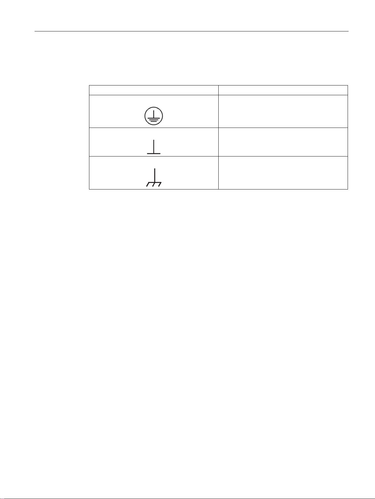
Ground symbols
Symbol
Meaning
Testing the protection against electric shock when using frequency converters
Background
Table 2 Symbols
Connection for protective conductor (PE)
Ground (e.g. M 24 V)
Connection for function potential bonding
Protection on indirect contact in the motor circuit of a converter and automatic disconnection
in case of a fault in accordance with DIN EN 60364-4-4 VDE 0100, part 410 is ensured if the
following conditions are met:
● The installation instructions provided in the documentation of the converter have been
followed, in particular, regarding
– Equipotential bonding
– Conductor cross section
– Fuse protection
● The valid standards were complied with during installation:
– DIN EN 50178 VDE 0160
– DIN EN 60204-1 VDE 0113, part 1
– DIN EN 60364-5-52 VDE 0100-520
– DIN EN 60364-5-54 VDE 0100-540
● Continuity of the PE conductor is ensured according to DIN VDE 0100-600 (IEC 60364-6)
Converters of the SINAMICS series meet the requirements defined in DIN EN 60364-4-41
VDE 0100, part 410 and comply with the specified break times.
In the case of a short-circuit with negligible impedance to ground, the converter interrupts the
circuit within the shortest time (<< 100 ms). As a consequence, there is very high impedance
between the converter DC link and the output (> 1 MΩ) so that the possible voltage as result
of the voltage divider with the impedance of the ground connection between the motor and
converter is less than 50 VAC or 120 VDC.
AC Drive
Manual, (GH6), 07/2016, 6SL3097-4AL00-0BP5
11

Foreword
AC Drive
12 Manual, (GH6), 07/2016, 6SL3097-4AL00-0BP5

Table of contents
Foreword ................................................................................................................................................ 5
1 Fundamental safety instructions ............................................................................................................ 21
2 System overview ................................................................................................................................... 29
3 Mains connection and line-side power components ............................................................................... 43
1.1 General safety instructions ..................................................................................................... 21
1.2 Safety instructions for electromagnetic fields (EMF) .............................................................. 25
1.3 Handling electrostatic sensitive devices (ESD) ...................................................................... 25
1.4 Industrial security .................................................................................................................... 26
1.5 Residual risks of power drive systems .................................................................................... 27
2.1 Field of application .................................................................................................................. 29
2.2 Platform Concept and Totally Integrated Automation ............................................................. 30
2.3 Overview, SINAMICS S120 AC Drive ..................................................................................... 32
2.4 SINAMICS S120 components ................................................................................................ 33
2.5 System data ............................................................................................................................ 34
2.5.1 System data for PM240-2 Blocksize Power Modules ............................................................. 34
2.5.2 Safety data for Power Modules, chassis format ..................................................................... 38
2.6 Derating .................................................................................................................................. 40
3.1 Introduction ............................................................................................................................. 43
3.2 Information on the disconnector unit ....................................................................................... 44
3.3 Overcurrent protection by means of line fuses and circuit breakers ...................................... 45
3.3.1 Power Modules, blocksize format ........................................................................................... 45
3.3.1.1 Line fuses for Power Modules blocksize format 200 V ........................................................... 45
3.3.1.2 Line fuses for Power Modules blocksize format 400 V ........................................................... 47
3.3.1.3 Line fuses for Power Modules blocksize format 690 V ........................................................... 50
3.3.2 Power Modules chassis format ............................................................................................... 52
3.3.2.1 Line fuses and circuit breaker for Power Modules, chassis format ........................................ 52
3.4 Using residual-current devices ............................................................................................... 53
3.5 Surge voltage protection ......................................................................................................... 54
3.6 Line contactors ........................................................................................................................ 54
3.7 Line filter ................................................................................................................................. 55
3.7.1 Description .............................................................................................................................. 55
3.7.2 Safety instructions for line filters ............................................................................................. 56
3.7.3 Electromagnetic compatibility (EMC) of the system ............................................................... 58
3.7.4 Dimension drawings ................................................................................................................ 59
3.7.5 Mounting ................................................................................................................................. 64
3.7.6 Technical data ......................................................................................................................... 65
AC Drive
Manual, (GH6), 07/2016, 6SL3097-4AL00-0BP5
13

Table of contents
4 Power Modules ..................................................................................................................................... 81
3.7.6.1 Technical data, Blocksize line filter ........................................................................................ 65
3.7.6.2 Technical data, Chassis line filter .......................................................................................... 66
3.8 Line reactors .......................................................................................................................... 67
3.8.1 Description ............................................................................................................................. 67
3.8.2 Safety instructions for line reactors ........................................................................................ 67
3.8.3 Dimension drawings ............................................................................................................... 69
3.8.4 Mounting ................................................................................................................................ 71
3.8.5 Electrical Connection ............................................................................................................. 72
3.8.6 Technical data ........................................................................................................................ 73
3.8.6.1 Blocksize line reactors ........................................................................................................... 73
3.8.6.2 Chassis line reactors .............................................................................................................. 74
3.9 Line connection variants ........................................................................................................ 74
3.9.1 Operation on different line system configurations .................................................................. 74
3.9.2 Methods of line connection .................................................................................................... 77
3.9.3 Operation of the line connection components on the supply line .......................................... 77
3.9.4 Operation of the line connection components via an autotransformer .................................. 79
3.9.5 Operation of the line connection components via an isolating transformer ........................... 79
4.1 Safety instructions for Power Modules .................................................................................. 81
4.2 Blocksize Power Modules (PM240-2) .................................................................................... 82
4.2.1 Description of PM240-2 ......................................................................................................... 82
4.2.2 Requirements for UL/cUL/CSA .............................................................................................. 85
4.2.3 Interface description ............................................................................................................... 87
4.2.3.1 Overview ................................................................................................................................ 87
4.2.3.2 Line supply connection .......................................................................................................... 92
4.2.3.3 Motor connection.................................................................................................................... 93
4.2.3.4 Braking resistor and DC link connection ................................................................................ 94
4.2.3.5 Safe brake relay connection .................................................................................................. 95
4.2.3.6 STO via Power Module terminals .......................................................................................... 96
4.2.4 Connection example .............................................................................................................. 98
4.2.5 Dimension drawings ............................................................................................................... 99
4.2.5.1 Power Modules with internal cooling...................................................................................... 99
4.2.5.2 Push through Power Modules .............................................................................................. 107
4.2.5.3 Drilling patterns .................................................................................................................... 111
4.2.6 Mounting .............................................................................................................................. 112
4.2.6.1 Mounting dimensions and tightening torques ...................................................................... 113
4.2.6.2 Mounting the shield connection plate .................................................................................. 114
4.2.7 Technical data ...................................................................................................................... 116
4.2.7.1 200 V Power Modules .......................................................................................................... 117
4.2.7.2 400 V Power Modules .......................................................................................................... 125
4.2.7.3 690 V Power Modules .......................................................................................................... 133
4.2.7.4 Characteristics ..................................................................................................................... 137
4.3 Power Modules Chassis ...................................................................................................... 140
4.3.1 Description ........................................................................................................................... 140
4.3.2 Interface description ............................................................................................................. 141
4.3.2.1 Overview .............................................................................................................................. 141
4.3.2.2 Terminal Block X9 ................................................................................................................ 143
4.3.2.3 DCPS, DCNS connection for a dv/dt filter ........................................................................... 143
4.3.2.4 X41 EP terminal / temperature sensor connection .............................................................. 143
AC Drive
14 Manual, (GH6), 07/2016, 6SL3097-4AL00-0BP5

Table of contents
5 DC link components ............................................................................................................................ 157
6 Motor-side power components ............................................................................................................ 185
4.3.2.5 X42 terminal strip .................................................................................................................. 145
4.3.2.6 X46 Brake control and monitoring ........................................................................................ 145
4.3.2.7 DRIVE-CLiQ interface X400-X402 ........................................................................................ 146
4.3.2.8 Meaning of the LEDs on the Power Module ......................................................................... 147
4.3.3 Connection example ............................................................................................................. 148
4.3.4 Dimension drawings .............................................................................................................. 149
4.3.5 Electrical connection ............................................................................................................. 151
4.3.6 Technical data ....................................................................................................................... 153
4.3.6.1 Characteristics ...................................................................................................................... 154
5.1 Blocksize ............................................................................................................................... 157
5.1.1 Braking resistors ................................................................................................................... 157
5.1.1.1 Description ............................................................................................................................ 157
5.1.1.2 Safety instructions for blocksize braking resistors ................................................................ 157
5.1.1.3 Connection examples ........................................................................................................... 158
5.1.1.4 Dimension drawings .............................................................................................................. 159
5.1.1.5 Installation ............................................................................................................................. 161
5.1.1.6 Technical data ....................................................................................................................... 162
5.2 Chassis ................................................................................................................................. 168
5.2.1 Braking Modules ................................................................................................................... 168
5.2.1.1 Description ............................................................................................................................ 168
5.2.1.2 Safety instructions for Braking Modules chassis format ....................................................... 169
5.2.1.3 Braking Module for frame size FX ........................................................................................ 170
5.2.1.4 Braking Module for frame size GX ........................................................................................ 171
5.2.1.5 Connection example ............................................................................................................. 172
5.2.1.6 Braking resistor connection X1 ............................................................................................. 172
5.2.1.7 X21 digital inputs/outputs ...................................................................................................... 173
5.2.1.8 S1 Threshold switch .............................................................................................................. 174
5.2.1.9 Installing a Braking Module in a Power Module, frame size FX ........................................... 175
5.2.1.10 Installing a Braking Module in a Power Module, frame size GX ........................................... 177
5.2.1.11 Technical data ....................................................................................................................... 178
5.2.2 Braking resistors ................................................................................................................... 179
5.2.2.1 Description ............................................................................................................................ 179
5.2.2.2 Safety instructions for braking resistors chassis format ....................................................... 180
5.2.2.3 Dimension drawing ............................................................................................................... 182
5.2.2.4 Electrical connection ............................................................................................................. 183
5.2.2.5 Technical data ....................................................................................................................... 184
6.1 Blocksize ............................................................................................................................... 185
6.1.1 Motor reactors ....................................................................................................................... 185
6.1.1.1 Description ............................................................................................................................ 185
6.1.1.2 Safety instructions for motor reactors ................................................................................... 186
6.1.1.3 Dimension drawings .............................................................................................................. 187
6.1.1.4 Mounting ............................................................................................................................... 190
6.1.1.5 Electrical connection ............................................................................................................. 190
6.1.1.6 Technical data ....................................................................................................................... 191
6.2 Chassis ................................................................................................................................. 193
6.2.1 Motor reactors ....................................................................................................................... 193
6.2.1.1 Description ............................................................................................................................ 193
AC Drive
Manual, (GH6), 07/2016, 6SL3097-4AL00-0BP5
15

Table of contents
7 Control Units, Control Unit Adapters and operating components ........................................................... 217
6.2.1.2 Safety instructions for motor reactors .................................................................................. 193
6.2.1.3 Dimension drawing .............................................................................................................. 195
6.2.1.4 Technical data ...................................................................................................................... 196
6.2.2 Sinusoidal filter ..................................................................................................................... 196
6.2.2.1 Description ........................................................................................................................... 196
6.2.2.2 Safety instructions for sine-wave filters ............................................................................... 197
6.2.2.3 Dimension drawing .............................................................................................................. 199
6.2.2.4 Technical data ...................................................................................................................... 200
6.2.3 dv/dt filter plus Voltage Peak Limiter ................................................................................... 201
6.2.3.1 Description ........................................................................................................................... 201
6.2.3.2 Safety instructions for dv/dt filter plus Voltage Peak Limiter ................................................ 202
6.2.3.3 Interface description ............................................................................................................. 204
6.2.3.4 Connecting the dv/dt filter plus Voltage Peak Limiter .......................................................... 205
6.2.3.5 Dimension drawing, dv/dt reactor ........................................................................................ 206
6.2.3.6 Dimension drawing of the voltage peak limiter .................................................................... 207
6.2.3.7 Technical data ...................................................................................................................... 208
6.2.4 dv/dt filter compact plus Voltage Peak Limiter ..................................................................... 209
6.2.4.1 Description ........................................................................................................................... 209
6.2.4.2 Safety instructions for dv/dt filter compact plus Voltage Peak Limiter ................................. 209
6.2.4.3 Interface description ............................................................................................................. 212
6.2.4.4 Connecting the dv/dt filter compact plus Voltage Peak Limiter ........................................... 213
6.2.4.5 Dimension drawing of dv/dt filter compact plus Voltage Peak Limiter ................................. 214
6.2.4.6 Technical data ...................................................................................................................... 216
7.1 Introduction .......................................................................................................................... 217
7.1.1 Control Units ........................................................................................................................ 217
7.1.2 Control Unit Adapter ............................................................................................................ 220
7.2 Safety instructions for Control Units and Control Unit Adapters .......................................... 221
7.3 Control Unit CU310-2 PN (PROFINET) ............................................................................... 223
7.3.1 Description ........................................................................................................................... 223
7.3.2 Interface description ............................................................................................................. 224
7.3.2.1 Overview .............................................................................................................................. 224
7.3.2.2 X22 serial interface (RS232) ................................................................................................ 225
7.3.2.3 X23 HTL/TTL/SSI encoder interface .................................................................................... 226
7.3.2.4 X100 DRIVE-CLiQ interface ................................................................................................ 229
7.3.2.5 X120 digital inputs (fail-safe)/EP terminal/temperature sensor ........................................... 229
7.3.2.6 X121 digital inputs/outputs ................................................................................................... 231
7.3.2.7 X124 Electronics power supply ............................................................................................ 232
7.3.2.8 X127 LAN (Ethernet) ............................................................................................................ 233
7.3.2.9 X130 digital input (fail safe) digital output ............................................................................ 234
7.3.2.10 X131 digital inputs/outputs and analog input ....................................................................... 235
7.3.2.11 X150 P1/P2 PROFINET ....................................................................................................... 236
7.3.2.12 Measuring sockets ............................................................................................................... 237
7.3.2.13 S5 DIP switch ....................................................................................................................... 237
7.3.2.14 DIAG button ......................................................................................................................... 237
7.3.2.15 RESET button ...................................................................................................................... 238
7.3.2.16 Memory card ........................................................................................................................ 238
7.3.3 Connection examples .......................................................................................................... 239
7.3.4 Meaning of the LEDs ........................................................................................................... 241
7.3.4.1 Function of the LEDs ........................................................................................................... 241
AC Drive
16 Manual, (GH6), 07/2016, 6SL3097-4AL00-0BP5

Table of contents
7.3.4.2 Behavior of the LEDs during booting .................................................................................... 241
7.3.4.3 Behavior of the LEDs in the operating state ......................................................................... 242
7.3.5 Dimension drawing ............................................................................................................... 244
7.3.6 Technical data ....................................................................................................................... 245
7.4 Control Unit CU310-2 DP (PROFIBUS)................................................................................ 245
7.4.1 Description ............................................................................................................................ 245
7.4.2 Interface description .............................................................................................................. 246
7.4.2.1 Overview ............................................................................................................................... 246
7.4.2.2 X21 PROFIBUS .................................................................................................................... 247
7.4.2.3 PROFIBUS address switch ................................................................................................... 248
7.4.2.4 X22 serial interface (RS232) ................................................................................................. 249
7.4.2.5 X23 HTL/TTL/SSI encoder interface ..................................................................................... 250
7.4.2.6 X100 DRIVE-CLiQ interface ................................................................................................. 253
7.4.2.7 X120 digital inputs (fail-safe)/EP terminal/temperature sensor ............................................ 253
7.4.2.8 X121 digital inputs/outputs .................................................................................................... 255
7.4.2.9 X124 Electronics power supply ............................................................................................. 256
7.4.2.10 X127 LAN (Ethernet)............................................................................................................. 257
7.4.2.11 X130 digital input (fail safe) digital output ............................................................................. 258
7.4.2.12 X131 digital inputs/outputs and analog input ........................................................................ 259
7.4.2.13 Measuring sockets ................................................................................................................ 260
7.4.2.14 S5 DIP switch ........................................................................................................................ 261
7.4.2.15 DIAG button .......................................................................................................................... 261
7.4.2.16 RESET button ....................................................................................................................... 261
7.4.2.17 Memory card ......................................................................................................................... 262
7.4.3 Connection examples ........................................................................................................... 263
7.4.4 Meaning of the LEDs ............................................................................................................ 265
7.4.4.1 Function of the LEDs ............................................................................................................ 265
7.4.4.2 Behavior of the LEDs during booting .................................................................................... 265
7.4.4.3 Behavior of the LEDs in the operating state ......................................................................... 266
7.4.5 Dimension drawing ............................................................................................................... 268
7.4.6 Technical data ....................................................................................................................... 269
7.5 Control Unit Adapter CUA31 ................................................................................................. 269
7.5.1 Description ............................................................................................................................ 269
7.5.2 Interface description .............................................................................................................. 270
7.5.2.1 Overview ............................................................................................................................... 270
7.5.2.2
X200-X202 DRIVE-CLiQ interfaces ...................................................................................... 271
7.5.2.3 X210 EP terminal / temperature sensor ................................................................................ 271
7.5.2.4 X224 electronics power supply ............................................................................................. 272
7.5.3 Connection example ............................................................................................................. 273
7.5.4 Meaning of the LEDs ............................................................................................................ 273
7.5.5 Dimension drawing ............................................................................................................... 274
7.5.6 Technical data ....................................................................................................................... 274
7.6 Control Unit Adapter CUA32 ................................................................................................. 275
7.6.1 Description ............................................................................................................................ 275
7.6.2 Interface description .............................................................................................................. 276
7.6.2.1 Overview ............................................................................................................................... 276
7.6.2.2 X200-X202 DRIVE-CLiQ interfaces ...................................................................................... 277
7.6.2.3 X210 EP terminal / temperature sensor ................................................................................ 277
7.6.2.4 X220 HTL/TTL/SSI encoder interface................................................................................... 279
7.6.2.5 X224 electronics power supply ............................................................................................. 280
7.6.3 Connection example ............................................................................................................. 281
AC Drive
Manual, (GH6), 07/2016, 6SL3097-4AL00-0BP5
17

Table of contents
8 Supplementary system components and encoder system integration ................................................... 289
7.6.4 Meaning of the LEDs ........................................................................................................... 281
7.6.5 Dimension drawing .............................................................................................................. 282
7.6.6 Technical data ...................................................................................................................... 282
7.7 Mounting Control Units and Control Unit Adapters .............................................................. 283
7.8 Basic Operator Panel BOP20 .............................................................................................. 284
7.8.1 Description ........................................................................................................................... 284
7.8.2 Interface description ............................................................................................................. 284
7.8.3 Mounting .............................................................................................................................. 287
8.1 Sensor Modules ................................................................................................................... 289
8.1.1 Safety instructions for Sensor Modules Cabinet-Mounted .................................................. 289
8.1.2 Sensor Module Cabinet-Mounted SMC10 ........................................................................... 291
8.1.2.1 Description ........................................................................................................................... 291
8.1.2.2 Interface description ............................................................................................................. 291
8.1.2.3 Meaning of the LEDs ........................................................................................................... 295
8.1.2.4 Dimension drawing .............................................................................................................. 296
8.1.2.5 Mounting .............................................................................................................................. 297
8.1.2.6 Technical data ...................................................................................................................... 298
8.1.3 Sensor Module Cabinet-Mounted SMC20 ........................................................................... 300
8.1.3.1 Description ........................................................................................................................... 300
8.1.3.2 Interface description ............................................................................................................. 300
8.1.3.3 Meaning of the LEDs ........................................................................................................... 304
8.1.3.4 Dimension drawing .............................................................................................................. 305
8.1.3.5 Mounting .............................................................................................................................. 306
8.1.3.6 Technical data ...................................................................................................................... 307
8.1.4 Sensor Module Cabinet-Mounted SMC30 ........................................................................... 308
8.1.4.1 Description ........................................................................................................................... 308
8.1.4.2 Interface description ............................................................................................................. 308
8.1.4.3 Connection examples .......................................................................................................... 314
8.1.4.4 Meaning of the LEDs ........................................................................................................... 316
8.1.4.5 Dimension drawing .............................................................................................................. 317
8.1.4.6 Mounting .............................................................................................................................. 318
8.1.4.7 Protective conductor connection and shield support ........................................................... 319
8.1.4.8 Technical data ...................................................................................................................... 319
8.2 Option module Safe Brake Relay......................................................................................... 324
8.2.1 Introduction .......................................................................................................................... 324
8.2.2 Safety instructions for Safe Brake Relays ........................................................................... 324
8.2.3 Interface description ............................................................................................................. 325
8.2.3.1 Overview .............................................................................................................................. 325
8.2.3.2 X524 electronics power supply ............................................................................................ 325
8.2.3.3 Brake connection ................................................................................................................. 326
8.2.4 Connection example ............................................................................................................ 326
8.2.5 Dimension drawing .............................................................................................................. 327
8.2.6 Mounting .............................................................................................................................. 327
8.2.7 Technical data ...................................................................................................................... 327
8.3 Safe Brake Adapter optional module
................................................................................... 328
8.3.1 Description ........................................................................................................................... 328
8.3.2 Safety instructions for Safe Brake Adapters ........................................................................ 329
8.3.3 Interface description ............................................................................................................. 330
AC Drive
18 Manual, (GH6), 07/2016, 6SL3097-4AL00-0BP5

Table of contents
9 Accessories ........................................................................................................................................ 335
10 Cabinet design and EMC for components, Blocksize format ................................................................ 349
8.3.3.1 Overview ............................................................................................................................... 330
8.3.3.2 X11 interface to the Control Interface Module ...................................................................... 331
8.3.3.3 X12 230 V AC power supply ................................................................................................. 331
8.3.3.4 X14 load connection ............................................................................................................. 331
8.3.3.5 X15 fast de-energization ....................................................................................................... 332
8.3.4 Connection example ............................................................................................................. 332
8.3.5 Dimension drawing ............................................................................................................... 333
8.3.6 Mounting ............................................................................................................................... 333
8.3.7 Technical data ....................................................................................................................... 333
9.1 DRIVE-CLiQ cabinet bushings ............................................................................................. 335
9.1.1 Description ............................................................................................................................ 335
9.1.2 Interface description .............................................................................................................. 336
9.1.2.1 Overview ............................................................................................................................... 336
9.1.3 Dimension drawings .............................................................................................................. 337
9.1.4 Installation ............................................................................................................................. 338
9.1.4.1 DRIVE-CLiQ cabinet bushing for cables with DRIVE-CLiQ connectors ............................... 338
9.1.4.2 DRIVE-CLiQ cabinet bushing for cables with M12 plug/socket ............................................ 340
9.1.5 Technical data ....................................................................................................................... 341
9.2 DRIVE-CLiQ coupling ........................................................................................................... 342
9.2.1 Description ............................................................................................................................ 342
9.2.2 Interface description .............................................................................................................. 342
9.2.2.1 Overview ............................................................................................................................... 342
9.2.3 Dimension drawing ............................................................................................................... 343
9.2.4 Mounting ............................................................................................................................... 343
9.2.5 Technical data ....................................................................................................................... 344
9.3 Mounting frame ..................................................................................................................... 345
9.3.1 Description ............................................................................................................................ 345
9.3.2 Dimension drawings FSA-FSC ............................................................................................. 345
9.3.3 Mounting ............................................................................................................................... 347
10.1 General information .............................................................................................................. 349
10.2 Safety instructions for control panel manufacturing .............................................................. 350
10.3 Information on electromagnetic compatibility (EMC) ............................................................ 351
10.3.1 General information .............................................................................................................. 351
10.3.2 Classification of EMC behavior ............................................................................................. 352
10.4 Cable shielding and routing .................................................................................................. 354
10.5 24 V DC Supply Voltage ....................................................................................................... 356
10.5.1 General ................................................................................................................................. 356
10.5.2 Overcurrent protection .......................................................................................................... 358
10.5.3 Overvoltage protection .......................................................................................................... 359
10.5.4 Typical 24 V current consumption of the components .......................................................... 359
10.5.5 Selecting power supply units ................................................................................................ 360
10.6 Connection Methods ............................................................................................................. 361
10.6.1 DRIVE-CLiQ signal cables .................................................................................................... 361
10.6.1.1 Overview ............................................................................................................................... 361
10.6.1.2 DRIVE-CLiQ signal cables without 24 V DC cores ............................................................... 362
AC Drive
Manual, (GH6), 07/2016, 6SL3097-4AL00-0BP5
19

Table of contents
11 Service and maintenance ..................................................................................................................... 383
A Appendix ............................................................................................................................................. 409
Index ................................................................................................................................................... 421
10.6.1.3 DRIVE-CLiQ signal cables MOTION-CONNECT with DRIVE-CLiQ connectors ................ 362
10.6.1.4 MOTION-CONNECT DRIVE-CLiQ signal cables with DRIVE-CLiQ connector and M12
socket ................................................................................................................................... 363
10.6.1.5 Comparison of DRIVE-CLiQ signal cables .......................................................................... 364
10.6.1.6 Combined use of MOTION-CONNECT 500 and MOTION-CONNECT 800PLUS .............. 366
10.6.2 Power cables for motors ...................................................................................................... 367
10.6.2.1 Configuring the cable length ................................................................................................ 367
10.6.2.2 Comparison of MOTION-CONNECT power cables ............................................................. 368
10.6.3 Current-carrying capacity and derating factors for power cables and signal cables ........... 369
10.6.4 Spring-loaded terminals ....................................................................................................... 371
10.6.5 Screw terminals.................................................................................................................... 371
10.7 Protective connection and equipotential bonding ................................................................ 372
10.8 Information on control cabinet cooling ................................................................................. 375
10.8.1 General ................................................................................................................................ 375
10.8.2 Ventilation ............................................................................................................................ 377
10.8.3 Power loss of components in rated operation ...................................................................... 379
10.8.3.1 General ................................................................................................................................ 379
10.8.3.2 Power loss of Control Units, Control Unit Adapters and Sensor Modules ........................... 379
10.8.3.3 Power loss for line reactors and line filters .......................................................................... 380
10.8.3.4 Power loss for Power Modules ............................................................................................ 380
11.1 Safety instructions for service and maintenance ................................................................. 383
11.2 Service and maintenance for components, Blocksize format .............................................. 384
11.2.1 Replacing hardware components ........................................................................................ 384
11.2.2 Replacing the fan CU310-2 DP and CU310-2 PN ............................................................... 384
11.2.3 Replacing the fan on the PM240-2 ...................................................................................... 386
11.3 Service and maintenance for Chassis format components ................................................. 387
11.3.1 Maintenance ......................................................................................................................... 388
11.3.2 Installation equipment .......................................................................................................... 389
11.3.3 Replacing components ........................................................................................................ 390
11.3.3.1 Replacing the Powerblock, Power Module, frame size FX .................................................. 390
11.3.3.2 Replacing the Powerblock, Power Module, frame size GX ................................................. 393
11.3.3.3 Replacing the Control Interface Module, Power Module, frame size FX ............................. 396
11.3.3.4 Replacing the Control Interface Module, Power Module, frame size GX ............................ 398
11.3.3.5 Replacing the fan, Power Module, frame size FX ................................................................ 400
11.3.3.6 Replacing the fan, Power Module, frame size GX ............................................................... 402
11.4 Forming the DC link capacitors ............................................................................................ 404
11.5 Recycling and disposal ........................................................................................................ 408
A.1 List of abbreviations ............................................................................................................. 409
A.2 Documentation overview ...................................................................................................... 419
AC Drive
20 Manual, (GH6), 07/2016, 6SL3097-4AL00-0BP5
1
1.1
General safety instructions
DANGER
Danger to life due to live parts and other energy sources
WARNING
Danger to life through a hazardous voltage when connecting an unsuitable power supply
Death or serious injury can result when live parts are touched.
• Only work on electrical devices when you are qualified for this job.
• Always observe the country-specific safety rules.
Generally, six steps apply when establishing safety:
1. Prepare for shutdown and notify all those who will be affected by the procedure.
2. Disconnect the machine from the supply.
– Switch off the machine.
– Wait until the discharge time specified on the warning labels has elapsed.
– Check that it really is in a no-voltage condition, from phase conductor to phase
conductor and phase conductor to protective conductor.
– Check whether the existing auxiliary supply circuits are de-energized.
– Ensure that the motors cannot move.
3. Identify all other dangerous energy sources, e.g. compressed air, hydraulic systems, or
water.
4. Isolate or neutralize all hazardous energy sources by closing switches, grounding or
short-circuiting or closing valves, for example.
5. Secure the energy sources against switching on again.
6. Ensure that the correct machine is completely interlocked.
After you have completed the work, restore the operational readiness in the inverse
sequence.
Touching live components can result in death or severe injury.
• Only use power supplies that provide SELV (Safety Extra Low Voltage) or PELV-
(Protective Extra Low Voltage) output voltages for all connections and terminals of the
electronics modules.
AC Drive
Manual, (GH6), 07/2016, 6SL3097-4AL00-0BP5
21
Fundamental safety instructions
WARNING
Danger to life when live parts are touched on damaged devices
WARNING
Danger to life through electric shock due to unconnected cable shields
WARNING
Danger to life due to electric shock when not grounded
WARNING
Danger to life due to electric shock when opening plug connections in operation
NOTICE
Material damage due to loose power connections
1.1 General safety instructions
Improper handling of devices can cause damage.
For damaged devices, hazardous voltages can be present at the enclosure or at exposed
components; if touched, this can result in death or severe injury.
• Ensure compliance with the limit values specified in the technical data during transport,
storage and operation.
• Do not use any damaged devices.
Hazardous touch voltages can occur through capacitive cross-coupling due to unconnected
cable shields.
• As a minimum, connect cable shields and the conductors of power cables that are not
used (e.g. brake cores) at one end at the grounded housing potential.
For missing or incorrectly implemented protective conductor connection for devices with
protection class I, high voltages can be present at open, exposed parts, which when
touched, can result in death or severe injury.
• Ground the device in compliance with the applicable regulations.
When opening plug connections in operation, arcs can result in severe injury or death.
• Only open plug connections when the equipment is in a no-voltage state, unless it has
been explicitly stated that they can be opened in operation.
Insufficient tightening torques or vibrations can result in loose electrical connections. This
can result in damage due to fire, device defects or malfunctions.
• Tighten all power connections with the specified tightening torques, e.g. line supply
connection, motor connection, DC link connections.
• Check all power connections at regular intervals. This applies in particular after
transport.
AC Drive
22 Manual, (GH6), 07/2016, 6SL3097-4AL00-0BP5

Fundamental safety instructions
WARNING
Danger to life due to fire spreading if housing is inadequate
WARNING
Danger to life through unexpected movement of machines when using mobile wireless
devices or mobile phones
WARNING
Danger to life due to the motor catching fire in the event of insulation overload
WARNING
Danger to life due to fire if overheating occurs because of insufficient ventilation clearances
1.1 General safety instructions
Fire and smoke development can cause severe personal injury or material damage.
• Install devices without a protective housing in a metal control cabinet (or protect the
device by another equivalent measure) in such a way that contact with fire is prevented.
• Ensure that smoke can only escape via controlled and monitored paths.
Using mobile wireless devices or mobile phones with a transmit power > 1 W closer than
approx. 2 m to the components may cause the devices to malfunction, influence the
functional safety of machines therefore putting people at risk or causing material damage.
• Switch the wireless devices or mobile phones off in the immediate vicinity of the
components.
There is higher stress on the motor insulation through a ground fault in an IT system. If the
insulation fails, it is possible that death or severe injury can occur as a result of smoke and
fire.
• Use a monitoring device that signals an insulation fault.
• Correct the fault as quickly as possible so the motor insulation is not overloaded.
Inadequate ventilation clearances can cause overheating of components with subsequent
fire and smoke. This can cause severe injury or even death. This can also result in
increased downtime and reduced service lives for devices/systems.
• Ensure compliance with the specified minimum clearance as ventilation clearance for
the respective component.
AC Drive
Manual, (GH6), 07/2016, 6SL3097-4AL00-0BP5
23
Fundamental safety instructions
WARNING
Danger of an accident occurring due to missing or illegible warning labels
NOTICE
Device damage caused by incorrect voltage/insulation tests
WARNING
Danger to life when safety functions are inactive
Note
Important safety notices for Safety Integrated functions
If you want to use Safety Integrated functions, you must observe the safety notices in the
Safety Integrated manuals.
1.1 General safety instructions
Missing or illegible warning labels can result in accidents involving death or serious injury.
• Check that the warning labels are complete based on the documentation.
• Attach any missing warning labels to the components, in the national language if
necessary.
• Replace illegible warning labels.
Incorrect voltage/insulation tests can damage the device.
• Before carrying out a voltage/insulation check of the system/machine, disconnect the
devices as all converters and motors have been subject to a high voltage test by the
manufacturer, and therefore it is not necessary to perform an additional test within the
system/machine.
Safety functions that are inactive or that have not been adjusted accordingly can cause
operational faults on machines that could lead to serious injury or death.
• Observe the information in the appropriate product documentation before
commissioning.
• Carry out a safety inspection for functions relevant to safety on the entire system,
including all safety-related components.
• Ensure that the safety functions used in your drives and automation tasks are adjusted
and activated through appropriate parameterizing.
• Perform a function test.
• Only put your plant into live operation once you have guaranteed that the functions
relevant to safety are running correctly.
AC Drive
24 Manual, (GH6), 07/2016, 6SL3097-4AL00-0BP5

Fundamental safety instructions
1.2
Safety instructions for electromagnetic fields (EMF)
WARNING
Danger to life from electromagnetic fields
1.3
Handling electrostatic sensitive devices (ESD)
NOTICE
Damage through electric fields or electrostatic discharge
1.2 Safety instructions for electromagnetic fields (EMF)
Electromagnetic fields (EMF) are generated by the operation of electrical power equipment
such as transformers, converters or motors.
People with pacemakers or implants are at a special risk in the immediate vicinity of these
devices/systems.
• Ensure that the persons involved are the necessary distance away (minimum 2 m).
Electrostatic sensitive devices (ESD) are individual components, integrated circuits, modules
or devices that may be damaged by either electric fields or electrostatic discharge.
Electric fields or electrostatic discharge can cause malfunctions through damaged
individual components, integrated circuits, modules or devices.
• Only pack, store, transport and send electronic components, modules or devices in their
original packaging or in other suitable materials, e.g conductive foam rubber of
aluminum foil.
• Only touch components, modules and devices when you are grounded by one of the
following methods:
– Wearing an ESD wrist strap
– Wearing ESD shoes or ESD grounding straps in ESD areas with conductive flooring
• Only place electronic components, modules or devices on conductive surfaces (table
with ESD surface, conductive ESD foam, ESD packaging, ESD transport container).
AC Drive
Manual, (GH6), 07/2016, 6SL3097-4AL00-0BP5
25
Fundamental safety instructions
1.4
Industrial security
Note
Industrial security
Siemens provides products and solutions with industrial security functions that support the
secure operation of plants, solutions, machines, equipment and/or networks. They are
importan
products and solutions undergo continuous development. Siemens recommends strongly
that you regularly check for product updates.
For the secure operation of Siemens product
preventive action (e.g. cell protection concept) and integrate each component into a holistic,
state
also be considered
(
To stay informed about product updates as they occur, sign up for a product
newsletter. For more information, visit this address (
).
WARNING
Danger as a result of unsafe operating states resulting from software manipulation
WARNING
Danger to life due to software manipulation when using exchangeable storage media
1.4 Industrial security
t components in a holistic industrial security concept. With this in mind, Siemens’
s and solutions, it is necessary to take suitable
-of-the-art industrial security concept. Third-party products that may be in use should
. For more information about industrial security, visit this address
http://www.siemens.com/industrialsecurity).
-specific
http://support.automation.siemens.com
Software manipulation (e.g. by viruses, Trojan horses, malware, worms) can cause unsafe
operating states to develop in your installation which can result in death, severe injuries
and/or material damage.
• Keep the software up to date.
You will find relevant information and newsletters at this address
(http://support.automation.siemens.com).
• Incorporate the automation and drive components into a holistic, state-of-the-art
industrial security concept for the installation or machine.
You will find further information at this address
(http://www.siemens.com/industrialsecurity).
• Make sure that you include all installed products into the holistic industrial security
concept.
Storing files onto exchangeable storage media amounts to an increased risk of infection,
e.g. with viruses and malware. As a result of incorrect parameterization, machines can
malfunction, which in turn can lead to injuries or death.
• Protect files stored on exchangeable storage media from malicious software by taking
suitable protection measures, e.g. virus scanners.
AC Drive
26 Manual, (GH6), 07/2016, 6SL3097-4AL00-0BP5

Fundamental safety instructions
1.5
Residual risks of power drive systems
1.5 Residual risks of power drive systems
When assessing the machine- or system-related risk in accordance with the respective local
regulations (e.g., EC Machinery Directive), the machine manufacturer or system installer
must take into account the following residual risks emanating from the control and drive
components of a drive system:
1. Unintentional movements of driven machine or system components during
commissioning, operation, maintenance, and repairs caused by, for example,
– Hardware and/or software errors in the sensors, control system, actuators, and cables
and connections
– Response times of the control system and of the drive
– Operation and/or environmental conditions outside the specification
– Condensation/conductive contamination
– Parameterization, programming, cabling, and installation errors
– Use of wireless devices/mobile phones in the immediate vicinity of electronic
components
– External influences/damage
– X-ray, ionizing radiation and cosmic radiation
2. Unusually high temperatures, including open flames, as well as emissions of light, noise,
particles, gases, etc., can occur inside and outside the components under fault conditions
caused by, for example:
– Component failure
– Software errors
– Operation and/or environmental conditions outside the specification
– External influences/damage
3. Hazardous shock voltages caused by, for example:
– Component failure
– Influence during electrostatic charging
– Induction of voltages in moving motors
– Operation and/or environmental conditions outside the specification
– Condensation/conductive contamination
– External influences/damage
4. Electrical, magnetic and electromagnetic fields generated in operation that can pose a
risk to people with a pacemaker, implants or metal replacement joints, etc., if they are too
close
5. Release of environmental pollutants or emissions as a result of improper operation of the
system and/or failure to dispose of components safely and correctly
For more information about the residual risks of the drive system components, see the
relevant sections in the technical user documentation.
AC Drive
Manual, (GH6), 07/2016, 6SL3097-4AL00-0BP5
27

Fundamental safety instructions
1.5 Residual risks of power drive systems
AC Drive
28 Manual, (GH6), 07/2016, 6SL3097-4AL00-0BP5

2
2.1
Field of application
SINAMICS is the family of drives from Siemens designed for machine and plant engineering
applications. SINAMICS offers solutions for all drive tasks:
● Simple pump and fan applications in the process industry.
● Complex single drives in centrifuges, presses, extruders, elevators, as well as conveyor
and transport systems
● Drive line-ups in textile, plastic film, and paper machines as well as in rolling mill plants.
● High precision servo drives in the manufacture of wind turbines
● Highly dynamic servo drives for machine tools, as well as packaging and printing
machines
Figure 2-1 SINAMICS applications
AC Drive
Manual, (GH6), 07/2016, 6SL3097-4AL00-0BP5
29

System overview
2.2
Platform Concept and Totally Integrated Automation
Totally Integrated Automation (TIA) with SINAMICS S120
Communication via PROFINET
Communication via PROFIBUS DP
2.2 Platform Concept and Totally Integrated Automation
Depending on the application, the SINAMICS range offers the ideal version for any drive
task.
● SINAMICS G is designed for standard applications with induction motors. These
applications have less stringent requirements regarding the dynamic performance of the
motor speed.
● SINAMICS S handles complex drive tasks with synchronous/induction motors and fulfills
stringent requirements regarding
– Dynamics and accuracy
– The integration of extensive technical functions in the drive control system
● SINAMICS DC MASTER is the DC drive belonging to the SINAMICS family. As a result of
its standard expandability, it addresses both basic as well as demanding drive
applications and in complementary markets.
All SINAMICS versions are based on a platform concept. Joint hardware and software
components, as well as standardized tools for design, configuration, and commissioning
tasks ensure high-level integration across all components. SINAMICS handles a wide variety
of drive tasks with no system gaps. The different SINAMICS versions can be easily
combined with each other.
SINAMICS is one of the core components of TIA alongside SIMATIC, SIMOTION and
SINUMERIK. It is thus possible to parameterize, program and commission all components in
the automation system via the STARTER commissioning tool using a standardized
engineering platform and without any system transitions. The system-wide data
management functions ensure consistent data and simplify archiving of the entire plant
project.
From V14, the Startdrive commissioning tool is an integral element of the TIA platform.
SINAMICS S120 supports communication via PROFINET and PROFIBUS DP.
This Ethernet-based bus enables control data to be exchanged at high speed via
PROFINET IO with IRT or RT and makes SINAMICS S120 a suitable choice for integration
in high-performance multi-axis applications. At the same time, PROFINET also uses
standard IT mechanisms (TCP/IP) to transport information, e.g. operating and diagnostic
data, to higher-level systems. This makes it easy to integrate into an IT corporate network.
This bus provides a high-performance, system-wide and integrated communication network
which links all automation components of the automation solution:
● HMI (operator control and monitoring)
● Control
● Drives and I/O
AC Drive
30 Manual, (GH6), 07/2016, 6SL3097-4AL00-0BP5
 Loading...