

Siemens SINAMICS PM240-2 Hardware Installation Manual


___________________
___________________
___________________
___________________
___________________
___________________
___________________
___________________
___________________
___________________
SINAMICS
SINAMICS G120
Power Module PM240-2
Hardware Installation Manual
01/2017
01/2017
A5E33294624B AE
Changes in this manual
1
Fundamental safety
instructions
2
Introduction
3
Installing/mounting
4
Connecting-up
5
Service and maintenance
6
Technical data
7
Spare parts
8
Accessories
9
Appendix
A

Siemens AG
Divisi
Postfach 48 48
90026 NÜRNBERG
GERMANY
A5E33294624B AE
Ⓟ
Copyright © Siemens AG 2013 - 2017.
All rights reserved
Legal information
Warning notice system
DANGER
indicates that death or severe personal injury will result if proper precautions are not taken.
WARNING
indicates that death or severe personal injury may result if proper precautions are not taken.
CAUTION
indicates that minor personal injury can result if proper precautions are not taken.
NOTICE
indicates that property damage can result if proper precautions are not taken.
Qualified Personnel
personnel qualified
Proper use of Siemens products
WARNING
Siemens products may only be used for the applications described in the catalog and in the relevant technical
maintenance are required to ensure that the products operate safely and without any problems. The permissible
ambient conditions must be complied with. The information in the relevant documentation must be observed.
Trademarks
Disclaimer of Liability
This manual contains notices you have to observe in order to ensure your personal safety, as well as to prevent
damage to property. The notices referring to your personal safety are highlighted in the manual by a safety alert
symbol, notices referring only to property damage have no safety alert symbol. These notices shown below are
graded according to the degree of danger.
If more than one degree of danger is present, the warning notice representing the highest degree of danger will
be used. A notice warning of injury to persons with a safety alert symbol may also include a warning relating to
property damage.
The product/system described in this documentation may be operated only by
task in accordance with the relevant documentation, in particular its warning notices and safety instructions.
Qualified personnel are those who, based on their training and experience, are capable of identifying risks and
avoiding potential hazards when working with these products/systems.
Note the following:
documentation. If products and components from other manufacturers are used, these must be recommended
or approved by Siemens. Proper transport, storage, installation, assembly, commissioning, operation and
All names identified by ® are registered trademarks of Siemens AG. The remaining trademarks in this publication
may be trademarks whose use by third parties for their own purposes could violate the rights of the owner.
We have reviewed the contents of this publication to ensure consistency with the hardware and software
described. Since variance cannot be precluded entirely, we cannot guarantee full consistency. However, the
information in this publication is reviewed regularly and any necessary corrections are included in subsequent
editions.
for the specific
on Digital Factory
02/2017 Subject to change

Table of contents
1 Changes in this manual ........................................................................................................................... 9
2 Fundamental safety instructions ............................................................................................................ 11
3 Introduction ........................................................................................................................................... 19
4 Installing/mounting ................................................................................................................................ 21
5 Connecting-up ...................................................................................................................................... 41
2.1 General safety instructions ..................................................................................................... 11
2.2 Handling electrostatic sensitive devices (ESD) ...................................................................... 16
2.3 Industrial security .................................................................................................................... 17
2.4 Residual risks of power drive systems .................................................................................... 18
3.1 Component specification according to UL .............................................................................. 20
3.2 Permissible motors ................................................................................................................. 20
4.1 Installation conditions.............................................................................................................. 21
4.2 EMC-compliant installation of a machine or system ............................................................... 23
4.2.1 Control cabinet ........................................................................................................................ 24
4.2.2 Cables ..................................................................................................................................... 25
4.2.3 Electromechanical components .............................................................................................. 28
4.3 Power losses and air cooling requirements ............................................................................ 29
4.4 Mounting the Power Modules ................................................................................................. 31
4.4.1 Dimension drawings and drilling dimensions for built-in units - IP20 devices ........................ 33
4.4.2 Hoisting gear FSD ... FSF ....................................................................................................... 35
4.4.3 Mounting the shield plate for built-in units .............................................................................. 35
4.4.4 Dimension drawings and drilling dimensions for PT Power Modules ..................................... 38
4.4.5 Mounting the shield plate for PT Power Modules ................................................................... 39
4.5 Additional components............................................................................................................ 39
5.1 Permissible line supplies ........................................................................................................ 44
5.1.1 TN line system ........................................................................................................................ 44
5.1.2 TT line system ......................................................................................................................... 45
5.1.3 IT system ................................................................................................................................ 46
5.1.4 Protective conductor ............................................................................................................... 47
5.2 Connecting the line and motor cable at the inverter ............................................................... 49
5.2.1 Connection overview............................................................................................................... 49
5.2.2 Length of the motor cable ....................................................................................................... 52
5.2.3 Connection terminals at the inverter ....................................................................................... 53
5.2.4 Establishing connections ........................................................................................................ 54
5.3 STO via Power Module terminals ........................................................................................... 57
5.4 Connecting the motor to the inverter in a star or delta connection ......................................... 58
Power Module PM240-2
Hardware Installation Manual, 01/2017, A5E33294624B AE
5

Table of contents
6 Service and maintenance ...................................................................................................................... 59
7 Technical data ...................................................................................................................................... 65
8 Spare parts .......................................................................................................................................... 103
9 Accessories ......................................................................................................................................... 105
6.1 Maintenance ........................................................................................................................... 60
6.2 Commissioning after a long storage time .............................................................................. 61
6.3 Replacing a fan ...................................................................................................................... 62
6.3.1 Fan replacement FSA … FSC ............................................................................................... 62
6.3.2 Fan replacement FSD … FSF ............................................................................................... 63
7.1 Electromagnetic compatibility - Overview .............................................................................. 65
7.2 Ambient conditions ................................................................................................................. 66
7.3 Overload capability of the inverter ......................................................................................... 68
7.4 Cable cross-sections and tightening torques ......................................................................... 70
7.5 Technical data, 200 V inverters ............................................................................................. 71
7.5.1 General data, 200 V inverters ................................................................................................ 71
7.5.2 Specific technical data, 200 V inverters ................................................................................. 73
7.5.3 Current derating depending on the pulse frequency, 200 V inverters ................................... 78
7.6 Technical data, 400 V inverters ............................................................................................. 79
7.6.1 General data, 400 V inverters ................................................................................................ 79
7.6.2 Specific technical data, 400 V inverters ................................................................................. 81
7.6.3 Current derating depending on the pulse frequency, 400 V inverters ................................... 87
7.7 Technical data, 690 V inverters ............................................................................................. 88
7.7.1 General data, 690 V inverters ................................................................................................ 88
7.7.2 Specific technical data, 690 V inverters ................................................................................. 90
7.7.3 Current derating depending on the pulse frequency, 690 V inverters ................................... 92
7.8 Restrictions for special ambient conditions ............................................................................ 93
7.9 Electromagnetic compatibility of variable-speed drives ......................................................... 96
7.9.1 Inverter applications ............................................................................................................... 97
7.9.1.1 Operation in the Second Environment ................................................................................... 97
7.9.1.2 Operation in the First Environment ........................................................................................ 99
7.9.2 Typical harmonic currents .................................................................................................... 100
7.9.3 EMC limit values in South Korea ......................................................................................... 101
9.1 Top shield plate - FSD … FSF ............................................................................................. 106
9.2 Mounting frames for PT power modules .............................................................................. 107
9.3 Line reactor .......................................................................................................................... 109
9.4 Line filter ............................................................................................................................... 113
9.5 Braking resistor .................................................................................................................... 115
9.5.1 Connecting a braking resistor .............................................................................................. 118
9.5.2 Technical data of the braking resistor .................................................................................. 119
9.6 Connecting a motor holding brake ....................................................................................... 122
9.6.1 Technical data of the brake relay? ....................................................................................... 122
9.6.2 Connections and circuit diagrams ........................................................................................ 123
Power Module PM240-2
6 Hardware Installation Manual, 01/2017, A5E33294624B AE

Table of contents
A Appendix............................................................................................................................................. 133
Index................................................................................................................................................... 141
9.6.3 Mounting and connecting the brake relay ............................................................................. 124
9.7 Output reactor ....................................................................................................................... 125
9.8 Voltage limiter and du/dt filter ............................................................................................... 130
A.1 Manuals and technical support ............................................................................................. 133
A.1.1 Manuals for your inverter ...................................................................................................... 133
A.1.2 Configuring support ............................................................................................................... 134
A.1.3 Product Support .................................................................................................................... 135
A.2 Disposal ................................................................................................................................ 136
A.3 Directives and standards ...................................................................................................... 137
A.4 Abbreviations ........................................................................................................................ 139
Power Module PM240-2
Hardware Installation Manual, 01/2017, A5E33294624B AE
7

Table of contents
Power Module PM240-2
8 Hardware Installation Manual, 01/2017, A5E33294624B AE

1
With respect to the PM240-2 Power Modules Manual, Edition 12/2015
The "EMC-compliant installation" section has been revised and moved to the
"Installation/mounting" chapter. It now has the title "EMC-compliant installation of a machine
or system".
The "Installing Power Modules" section has been revised.
The "Connecting" chapter has been restructured. "Connecting the motor to the inverter in a
star or delta connection" section has been revised.
The "Technical data" chapter has been revised and restructured.
Power Module PM240-2
Hardware Installation Manual, 01/2017, A5E33294624B AE
9

Changes in this manual
Power Module PM240-2
10 Hardware Installation Manual, 01/2017, A5E33294624B AE
2
2.1
General safety instructions
DANGER
Danger to life due to live parts and other energy sources
WARNING
Danger to life through a hazardous voltage when connecting an unsuitable power supply
Death or serious injury can result when live parts are touched.
• Only work on electrical devices when you are qualified for this job.
• Always observe the country-specific safety rules.
Generally, six steps apply when establishing safety:
1. Prepare for shutdown and notify all those who will be affected by the procedure.
2. Disconnect the machine from the supply.
– Switch off the machine.
– Wait until the discharge time specified on the warning labels has elapsed.
– Check that it really is in a no-voltage condition, from phase conductor to phase
conductor and phase conductor to protective conductor.
– Check whether the existing auxiliary supply circuits are de-energized.
– Ensure that the motors cannot move.
3. Identify all other dangerous energy sources, e.g. compressed air, hydraulic systems, or
water.
4. Isolate or neutralize all hazardous energy sources by closing switches, grounding or
short-circuiting or closing valves, for example.
5. Secure the energy sources against switching on again.
6. Ensure that the correct machine is completely interlocked.
After you have completed the work, restore the operational readiness in the inverse
sequence.
Touching live components can result in death or severe injury.
• Only use power supplies that provide SELV (Safety Extra Low Voltage) or PELV-
(Protective Extra Low Voltage) output voltages for all connections and terminals of the
electronics modules.
Power Module PM240-2
Hardware Installation Manual, 01/2017, A5E33294624B AE
11
Fundamental safety instructions
WARNING
Danger to life when live parts are touched on damaged devices
WARNING
Danger to life through electric shock due to unconnected cable shields
WARNING
Danger to life due to electric shock when not grounded
WARNING
Danger to life due to electric shock when opening plug connections in operation
WARNING
Danger to life through electric shock due to the residual charge of the power component
capacitors
2.1 General safety instructions
Improper handling of devices can cause damage.
For damaged devices, hazardous voltages can be present at the enclosure or at exposed
components; if touched, this can result in death or severe injury.
• Ensure compliance with the limit values specified in the technical data during transport,
storage and operation.
• Do not use any damaged devices.
Hazardous touch voltages can occur through capacitive cross-coupling due to unconnected
cable shields.
• As a minimum, connect cable shields and the conductors of power cables that are not
used (e.g. brake cores) at one end at the grounded housing potential.
For missing or incorrectly implemented protective conductor connection for devices with
protection class I, high voltages can be present at open, exposed parts, which when
touched, can result in death or severe injury.
• Ground the device in compliance with the applicable regulations.
When opening plug connections in operation, arcs can result in severe injury or death.
• Only open plug connections when the equipment is in a no-voltage state, unless it has
been explicitly stated that they can be opened in operation.
Because of the capacitors, a hazardous voltage is present for up to 5 minutes after the
power supply has been switched off. Contact with live parts can result in death or serious
injury.
• Wait for 5 minutes before you check that the unit really is in a no-voltage condition and
start work.
Power Module PM240-2
12 Hardware Installation Manual, 01/2017, A5E33294624B AE

Fundamental safety instructions
NOTICE
Material damage due to loose power connections
WARNING
Danger to life due to fire spreading if housing is inadequate
WARNING
Danger to life from electromagnetic fields
WARNING
Danger to life through unexpected movement of machines when using mobile wireless
devices or mobile phones
2.1 General safety instructions
Insufficient tightening torques or vibrations can result in loose electrical connections. This
can result in damage due to fire, device defects or malfunctions.
• Tighten all power connections with the specified tightening torques, e.g. line supply
connection, motor connection, DC link connections.
• Check all power connections at regular intervals. This applies in particular after
transport.
Fire and smoke development can cause severe personal injury or material damage.
• Install devices without a protective housing in a metal control cabinet (or protect the
device by another equivalent measure) in such a way that contact with fire is prevented.
• Ensure that smoke can only escape via controlled and monitored paths.
Electromagnetic fields (EMF) are generated by the operation of electrical power equipment,
such as transformers, converters, or motors.
People with pacemakers or implants are at particular risk in the immediate vicinity of this
equipment.
• If you have a heart pacemaker or implant, maintain a minimum distance of 2 m from
electrical power equipment.
Using mobile wireless devices or mobile phones with a transmit power > 1 W closer than
approx. 2 m to the components may cause the devices to malfunction, influence the
functional safety of machines therefore putting people at risk or causing material damage.
• Switch the wireless devices or mobile phones off in the immediate vicinity of the
components.
Power Module PM240-2
Hardware Installation Manual, 01/2017, A5E33294624B AE
13

Fundamental safety instructions
WARNING
Danger to life due to the motor catching fire in the event of insulation overload
WARNING
Danger to life due to fire if overheating occurs because of insufficient ventilation clearances
WARNING
Danger of an accident occurring due to missing or illegible warning labels
NOTICE
Device damage caused by incorrect voltage/insulation tests
2.1 General safety instructions
There is higher stress on the motor insulation through a ground fault in an IT system. If the
insulation fails, it is possible that death or severe injury can occur as a result of smoke and
fire.
• Use a monitoring device that signals an insulation fault.
• Correct the fault as quickly as possible so the motor insulation is not overloaded.
Inadequate ventilation clearances can cause overheating of components with subsequent
fire and smoke. This can cause severe injury or even death. This can also result in
increased downtime and reduced service lives for devices/systems.
• Ensure compliance with the specified minimum clearance as ventilation clearance for
the respective component.
Missing or illegible warning labels can result in accidents involving death or serious injury.
• Check that the warning labels are complete based on the documentation.
• Attach any missing warning labels to the components, in the national language if
necessary.
• Replace illegible warning labels.
Incorrect voltage/insulation tests can damage the device.
• Before carrying out a voltage/insulation check of the system/machine, disconnect the
devices as all converters and motors have been subject to a high voltage test by the
manufacturer, and therefore it is not necessary to perform an additional test within the
system/machine.
Power Module PM240-2
14 Hardware Installation Manual, 01/2017, A5E33294624B AE

Fundamental safety instructions
WARNING
Danger to life when safety functions are inactive
Note
Important safety notices for Safety Integrated functions
If you want to use Safety Integrated functions, you must observe the safety notices in the
Safety Integrated manuals.
2.1 General safety instructions
Safety functions that are inactive or that have not been adjusted accordingly can cause
operational faults on machines that could lead to serious injury or death.
• Observe the information in the appropriate product documentation before
commissioning.
• Carry out a safety inspection for functions relevant to safety on the entire system,
including all safety-related components.
• Ensure that the safety functions used in your drives and automation tasks are adjusted
and activated through appropriate parameterizing.
• Perform a function test.
• Only put your plant into live operation once you have guaranteed that the functions
relevant to safety are running correctly.
Power Module PM240-2
Hardware Installation Manual, 01/2017, A5E33294624B AE
15

Fundamental safety instructions
2.2
Handling electrostatic sensitive devices (ESD)
NOTICE
Damage through electric fields or electrostatic discharge
2.2 Handling electrostatic sensitive devices (ESD)
Electrostatic sensitive devices (ESD) are individual components, integrated circuits, modules
or devices that may be damaged by either electric fields or electrostatic discharge.
Electric fields or electrostatic discharge can cause malfunctions through damaged
individual components, integrated circuits, modules or devices.
• Only pack, store, transport and send electronic components, modules or devices in their
original packaging or in other suitable materials, e.g conductive foam rubber of
aluminum foil.
• Only touch components, modules and devices when you are grounded by one of the
following methods:
– Wearing an ESD wrist strap
– Wearing ESD shoes or ESD grounding straps in ESD areas with conductive flooring
• Only place electronic components, modules or devices on conductive surfaces (table
with ESD surface, conductive ESD foam, ESD packaging, ESD transport container).
Power Module PM240-2
16 Hardware Installation Manual, 01/2017, A5E33294624B AE

Fundamental safety instructions
2.3
Industrial security
Note
Industrial security
Siemens provides products and solutions with industrial security functions that support the
secure operation of plants, systems, machines and networks.
In order to protect plants, systems, machines and networks against cyber threats, it is
necess
security concept. Siemens products and solutions only represent one component of such a
concept.
The customer is responsible for preventing unauthorized access to its pl
machines and networks. Systems, machines and components should only be connected to
the enterprise network or the internet if and to the extent necessary and with appropriate
security measures (e.g. use of firewalls and network segmentation)
Additionally, Siemens’ guidance on appropriate security measures should be taken into
account. For more information about industrial security, please visit:
Industrial security (
Siemens’ products and solutions undergo continuous development to make them more
secure. Siemens strongly recommends to apply product updates as soon as available and to
always use the latest product versions. Use of product versions that are no longer supported,
and failure to apply latest updates may increase customer’s exposure to cyber threats.
To stay informed about product updates, subscribe to the Siemens Industrial Security RSS
Feed at:
Industrial security (
WARNING
Danger to life as a result of unsafe operating states resulting from software manipulation
2.3 Industrial security
ary to implement – and continuously maintain – a holistic, state-of-the-art industrial
ants, systems,
in place.
http://www.siemens.com/industrialsecurity).
http://www.siemens.com/industrialsecurity).
Software manipulations (e.g. viruses, trojans, malware or worms) can cause unsafe
operating states in your system that may lead to death, serious injury, and property
damage.
• Keep the software up to date.
• Incorporate the automation and drive components into a holistic, state-of-the-art
industrial security concept for the installation or machine.
• Make sure that you include all installed products into the holistic industrial security
concept.
• Protect files stored on exchangeable storage media from malicious software by with
suitable protection measures, e.g. virus scanners.
Power Module PM240-2
Hardware Installation Manual, 01/2017, A5E33294624B AE
17

Fundamental safety instructions
2.4
Residual risks of power drive systems
2.4 Residual risks of power drive systems
When assessing the machine- or system-related risk in accordance with the respective local
regulations (e.g., EC Machinery Directive), the machine manufacturer or system installer
must take into account the following residual risks emanating from the control and drive
components of a drive system:
1. Unintentional movements of driven machine or system components during
commissioning, operation, maintenance, and repairs caused by, for example,
– Hardware and/or software errors in the sensors, control system, actuators, and cables
and connections
– Response times of the control system and of the drive
– Operation and/or environmental conditions outside the specification
– Condensation/conductive contamination
– Parameterization, programming, cabling, and installation errors
– Use of wireless devices/mobile phones in the immediate vicinity of electronic
components
– External influences/damage
– X-ray, ionizing radiation and cosmic radiation
2. Unusually high temperatures, including open flames, as well as emissions of light, noise,
particles, gases, etc., can occur inside and outside the components under fault conditions
caused by, for example:
– Component failure
– Software errors
– Operation and/or environmental conditions outside the specification
– External influences/damage
3. Hazardous shock voltages caused by, for example:
– Component failure
– Influence during electrostatic charging
– Induction of voltages in moving motors
– Operation and/or environmental conditions outside the specification
– Condensation/conductive contamination
– External influences/damage
4. Electrical, magnetic and electromagnetic fields generated in operation that can pose a
risk to people with a pacemaker, implants or metal replacement joints, etc., if they are too
close
5. Release of environmental pollutants or emissions as a result of improper operation of the
system and/or failure to dispose of components safely and correctly
6. Influence of network-connected communication systems, e.g. ripple-control transmitters
or data communication via the network
For more information about the residual risks of the drive system components, see the
relevant sections in the technical user documentation.
Power Module PM240-2
18 Hardware Installation Manual, 01/2017, A5E33294624B AE

3
Overview
•
0.55
for line voltages from 1
•
0.55
for line voltages from 3
•
0.55
for line voltages from 3
•
1
for line voltages from 3
Control Units for the Power Modules
Note
Commissioning the inverter
You must first commission the inverter before you can use i
the Operating Instructions of the relevant Control Unit.
STO independent of the Control Unit
The Power Modules belong to the modular family of SINAMICS G120 inverters. A modular
inverter comprises Control Unit and Power Module.
Depending on the power rating in frame sizes FSA … FSF, the following Power Module
versions are supplied:
1 AC 200 V
kW … 4 kW
AC 200 V … 240 V
3 AC 200 V
3 AC 400 V
3 AC 690 V
You can operate the Power Modules with a Control Unit from one of the following listed
families.
● CU230P-2
● CU240B-2
● CU240E-2
● CU250S-2
For Power Modules FSA … FSC, you require a Control Unit with firmware version V4.4 or
higher.
For Power Modules FSD … FSF, you require a Control Unit with firmware version V4.7 HF8
or higher.
kW … 55 kW
kW … 132 kW
1 kW … 132 kW
AC 200 V … 240 V
AC 380 V … 480 V
AC 500 V … 690 V
Manuals for your inverter (Page 133)
Using the PM240-2 Power Modules, frame sizes FSD, FSE and FSF, you can implement the
"Safe Torque Off" safety function (STO), corresponding to PL e according to EN 13849-1
and SIL 3 according to IEC61508.
STO via Power Module terminals (Page 57).
Power Module PM240-2
Hardware Installation Manual, 01/2017, A5E33294624B AE
t. Commissioning is described in
19

Introduction
3.1
Component specification according to UL
3.2
Permissible motors
Note
Motors for inverter operation
Only use motors that are suitable for operation with inverters with a DC link.
Motors for 200 V Power Modules
Motors for 400 V Power Modules
Motors for 690 V Power Modules
3.1 Component specification according to UL
The inverters have UL approval according to UL508C and CSA C22.2 No. 274-13.
Further information and a link for downloading the appropriate certificates can be found in
the following Section:
Directives and standards (Page 137)
For the 200 V Power Modules, induction motors are permissible in the range from
25% … 150% of the inverter power without any restrictions.
For the 400 V Power Modules, induction motors are permissible in the range from
25 % … 150 % of the inverter power without any restrictions.
For the 690 V Power Modules, induction motors are permissible in the range from 50
% … 150 % of the inverter power without any restrictions.
Power Module PM240-2
20 Hardware Installation Manual, 01/2017, A5E33294624B AE

4
4.1
Installation conditions
General installation conditions
Inverters for systems in the United States / Canada (UL/cUL)
cable protection
When installing the Power Modules carefully observe the conditions listed below in order to
guarantee reliable, continuous and disturbance-free operation.
● The Power Modules are designed for installation in a control cabinet.
● The Power Modules are certified for use in environments with degree of pollution 2
without condensation; i.e. in environments where no conductive pollution/dirt occurs.
● The built-in units fulfill IP20 degree of protection.
● Devices with push-through technology (PT devices) have IP20 degree of protection,
at the rear of the control cabinet, IP55.
● You can find the permissible conductor cross-sections for the terminals in:
Connection terminals at the inverter (Page 53)
● The following section describes how you can install the Power Modules in compliance
with EMC regulations:
EMC-compliant installation of a machine or system (Page 23)
● For a system configuration in conformance with UL/cUL, use the fuse types approved for
UL/cUL, specified in the Technical data, or the circuit breakers under the following
Internet address.
–
–
● The integrated semiconductor short-circuit protection does not provide cable protection.
● On the system side, provide
and the local regulations.
● The inverters provide internal motor protection corresponding to UL61800-5-1. The
protection threshold is 115 % of the inverter full load current. When commissioning, you
can adapt the motor overload protection using parameter p0640.
Fuse types: Technical data (Page 65)
Circuit breaker
(https://support.industry.siemens.com/cs/ww/en/view/109486009)
in conformance with NEC or CEC, Part 1
● For frame size FSF, to connect the line supply and motor only use UL approved ring-type
cable lugs (ZMVV), which are certified for the particular voltage, with a permissible
current of at least 125 % of the input and output current. Use the higher value as basis.
Power Module PM240-2
Hardware Installation Manual, 01/2017, A5E33294624B AE
21

Installing/mounting
Additional requirements for CSA compliance, frame sizes FSA … FSC
Additional requirements relating to CSA conformance, frame sizes FSD … FSF
Line voltage
Phase to ground
Phase to phase
Rated
voltage
VPR
Rated
voltage
VPR
Grounded neutral conductor
139 V
2.5 kV
240 V
4 kV
Grounded line conductor
240 V
4 kV
240 V
4 kV
Grounded line conductor
480 V
6 kV
480 V
4 kV
Grounded neutral conductor
347 V
6 kV
600 V
4 kV
Grounded line conductor
600 V
6 kV
600 V
4 kV
4.1 Installation conditions
● Carefully note that for plants and systems in conformance with UL/cUL, the line and
output voltage may not be higher than 600 V.
● Only use copper cables rated for 60 °C or 75 °C.
● For frame size FSE inverters, use only cables certified for temperatures of 75° C to
connect the braking resistor.
● The DC-link terminals, DCP and DCN, were not investigated regarding conformance with
UL/cUL.
Install the inverter with an external suppression device with the following properties:
● Surge protection device with the appropriate certification (category checking numbers
VZCA and VZCA7)
● Rated supply voltage
– 240 V (phase with respect to ground), 240 V (phase to phase) for 200 V inverters
– 480 V (phase with respect to ground), 480 V (phase to phase) for 400 V inverters
● Terminal voltage, V
= 2000 V
PR
● Suitable for SPD applications, type 1 or type 2
Alternatively, use a surge protection device, article number 5SD7 424-1 from Siemens AG.
Overvoltage category OVC III must be ensured for all connections of the power circuit. This
can mean that a surge suppressor must connected upstream on the line side. The rated
voltage of the surge suppressor must not exceed the line voltage, and must guarantee the
limit values (VPR) specified here.
3 AC 200 V … 240 V
3 AC 380 V … 480 V Grounded neutral conductor 277 V 4 kV 480 V 4 kV
3 AC 500 V … 600 V
Power Module PM240-2
22 Hardware Installation Manual, 01/2017, A5E33294624B AE
Installing/mounting
4.2
EMC-compliant installation of a machine or system
EMC zones
Inside the control cabinet
Outside the control cabinet
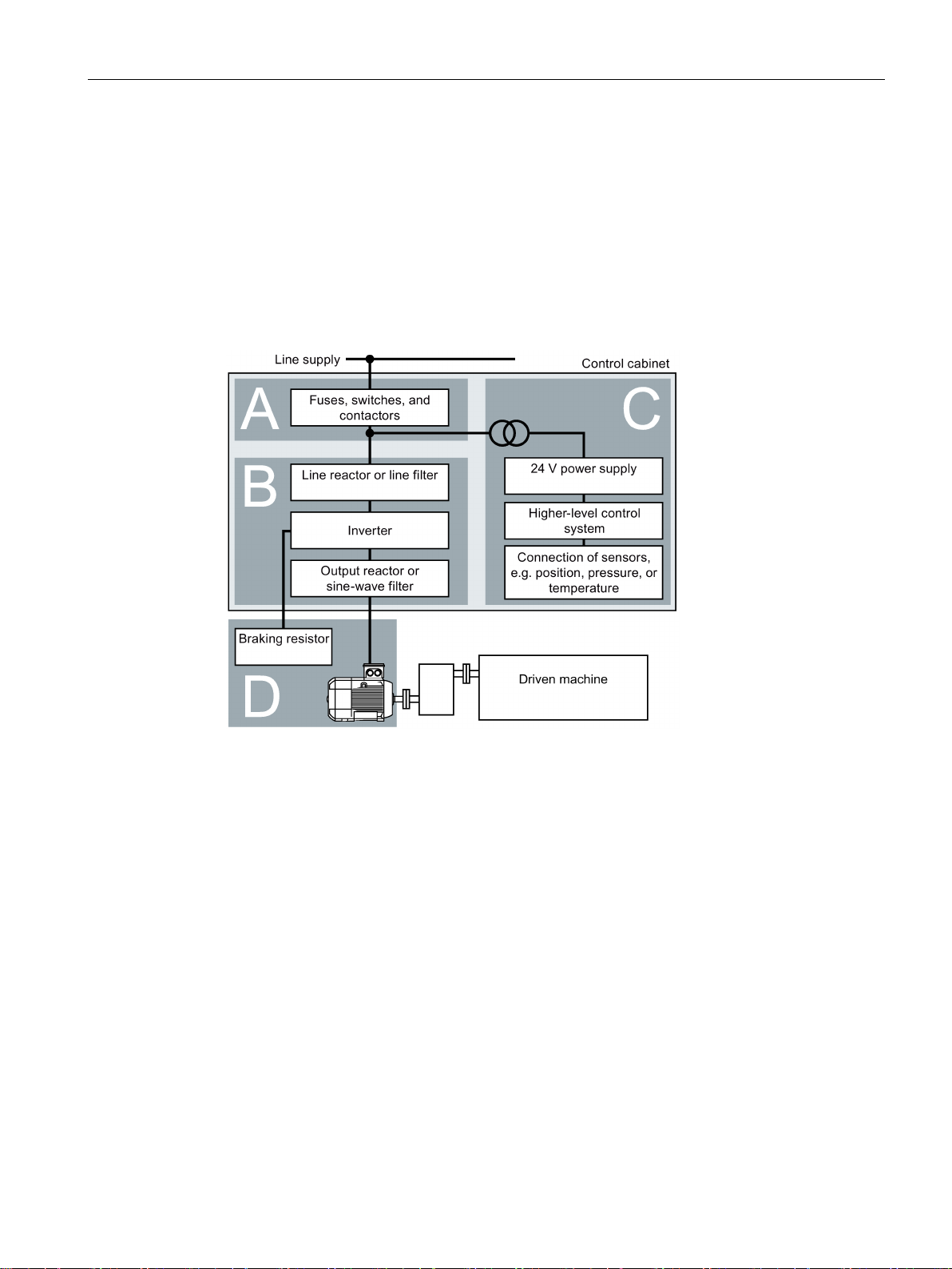
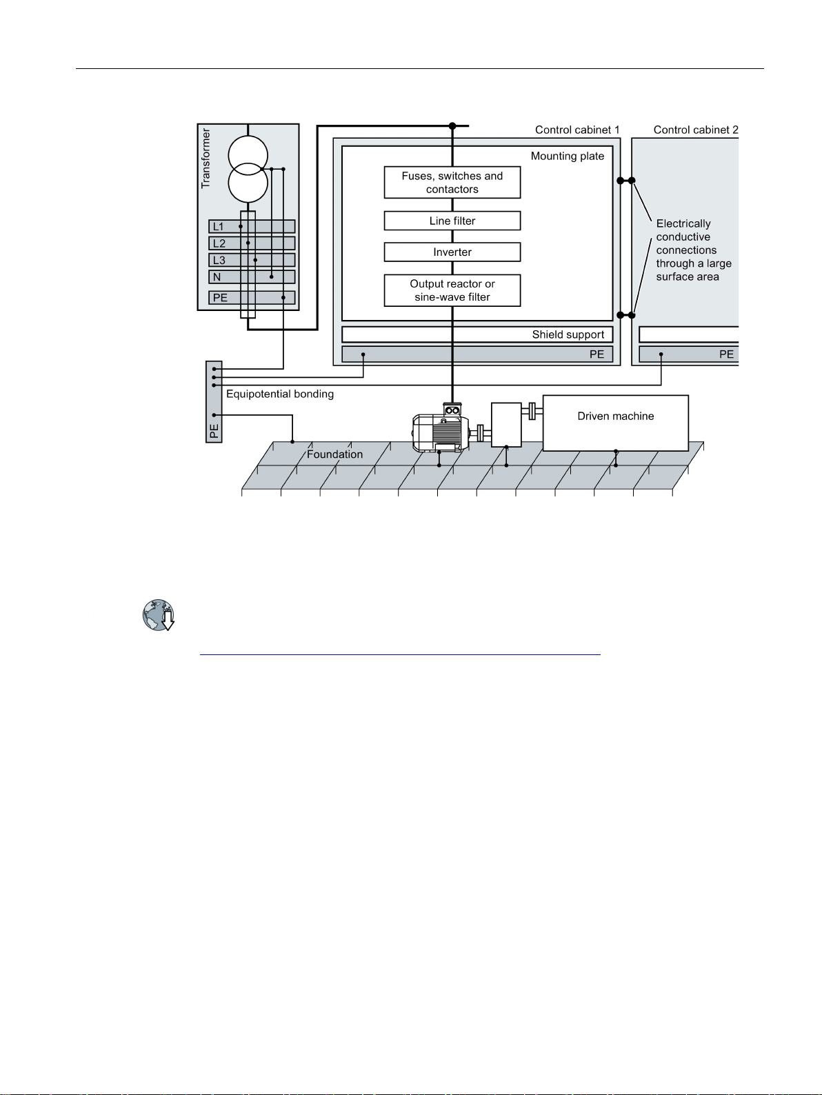
4.2 EMC-compliant installation of a machine or system
The inverter is designed for operation in industrial environments where strong
electromagnetic fields are to be expected.
Reliable and disturbance-free operation is only guaranteed for EMC-compliant installation.
To achieve this, subdivide the control cabinet and the machine or system into EMC zones:
Figure 4-1 Example of the EMC zones of a plant or machine
● Zone A: Line supply connection
● Zone B: Power electronics
Devices in Zone B generate energy-rich electromagnetic fields.
● Zone C: Control and sensors
Devices in Zone C do not generate any energy-rich electromagnetic fields themselves,
but their functions can be impaired by electromagnetic fields.
● Zone D: Motors, braking resistors
Devices in Zone D generate electromagnetic fields with a significant amount of energy
Power Module PM240-2
Hardware Installation Manual, 01/2017, A5E33294624B AE
23

Installing/mounting
4.2.1
Control cabinet
Control cabinet assembly
Measures required for several control cabinets
4.2 EMC-compliant installation of a machine or system
● Assign the various devices to zones in the control cabinet.
● Electromagnetically uncouple the zones from each other by means of one of the following
actions:
– Side clearance ≥ 25 cm
– Separate metal enclosure
– Large-area partition plates
● Route cables of various zones in separate cable harnesses or cable ducts.
● Install filters or isolation amplifiers at the interfaces of the zones.
● Connect the door, side panels, top and base plate of the control cabinet with the control
cabinet frame using one of the following methods:
– Electrical contact surface of several cm² for each contact location
– Several screw connections
– Short, finely stranded, braided copper wires with cross-sections
≥ 95 mm² / 000 (3/0) (-2) AWG
● Install a shield support for shielded cables that are routed out of the control cabinet.
● Connect the PE bar and the shield support to the control cabinet frame through a large
surface area to establish a good electrical connection.
● Mount the control cabinet components on a bare metal mounting plate.
● Connect the mounting plate to the control cabinet frame and PE bar and shield support
through a large surface area to establish a good electrical connection.
● For screw connections onto painted or anodized surfaces, establish a good conductive
contact using one of the following methods:
– Use special (serrated) contact washers that cut through the painted or anodized
surface.
– Remove the insulating coating at the contact locations.
● Install equipotential bonding for all control cabinets.
● Screw the frames of the control cabinets together at several locations through a large
surface area using serrated washers to establish a good electrical connection.
● In plants and systems where the control cabinets are lined up next to one another, and
which are installed in two groups back to back, connect the PE bars of the two cabinet
groups at as many locations as possible.
Power Module PM240-2
24 Hardware Installation Manual, 01/2017, A5E33294624B AE
Installing/mounting
Further information
4.2.2
Cables
4.2 EMC-compliant installation of a machine or system
Figure 4-2 Grounding and high-frequency equipotential bonding measures in the control cabinet
Additional information about EMC-compliant installation is available in the Internet:
EMC installation guideline
(https://support.industry.siemens.com/cs/ww/de/view/60612658/en)
Cables with a high level of interference and cables with a low level of interference are
connected to the inverter:
● Cables with a high level of interference:
and in the plant/system
– Cable between the line filter and inverter
– Motor cable
– Cable at the inverter DC link connection
– Cable between the inverter and braking resistor
● Cables with a low level of interference:
– Cable between the line and line filter
– Signal and data cables
Power Module PM240-2
Hardware Installation Manual, 01/2017, A5E33294624B AE
25
Installing/mounting
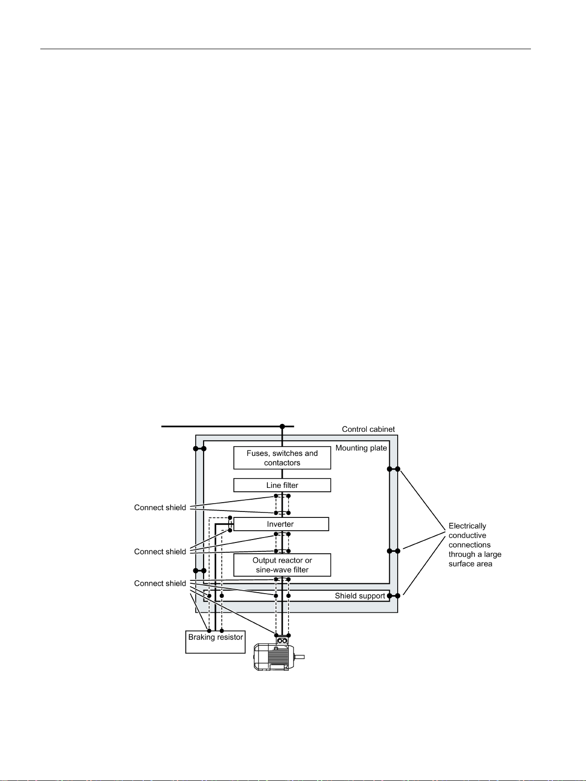
Cable routing inside the cabinet
4.2 EMC-compliant installation of a machine or system
● Route the power cables with a high level of interference so that there is a minimum
clearance of 25 cm to cables with a low level of interference.
If the minimum clearance of 25 cm is not possible, insert separating metal sheets
between the cables with a high level of interference and cables with a low level of
interference. Connect these separating metal sheets to the mounting plate to establish a
good electrical connection.
● Cables with a high level of interference and cables with a low level of interference may
only cross over at right angles:
● Keep all of the cables as short as possible.
● Route all of the cables close to the mounting plates or cabinet frames.
● Route signal and data cables - as well as the associated equipotential bonding cables -
parallel and close to one another.
● Twist incoming and outgoing unshielded individual conductors.
Alternatively, you can route incoming and outgoing conductors in parallel, but close to
one another.
● Ground any unused conductors of signal and data cables at both ends.
● Signal and data cables must only enter the cabinet from one side, e.g. from below.
● Using shielded cables for the following connections:
– Cable between the inverter and line filter
– Cable between the inverter and output reactor or sine-wave filter
Figure 4-3 Routing inverter cables inside and outside a control cabinet
Power Module PM240-2
26 Hardware Installation Manual, 01/2017, A5E33294624B AE
Installing/mounting
Routing cables outside the control cabinet
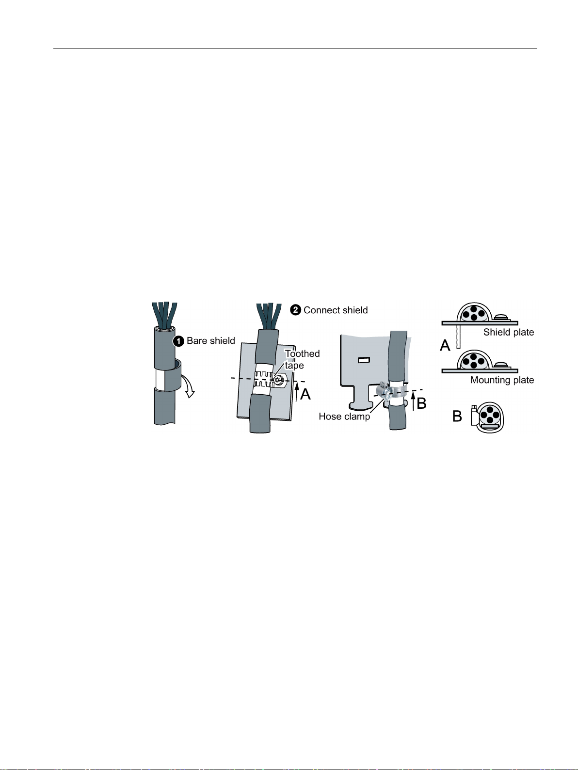
Requirements relating to shielded cables
4.2 EMC-compliant installation of a machine or system
● Maintain a minimum clearance of 25 cm between cables with a high level of interference
and cables with a low level of interference.
● Using shielded cables for the following connections:
– Inverter motor cable
– Cable between the inverter and braking resistor
– Signal and data cables
● Connect the motor cable shield to the motor enclosure using a PG gland that establishes
a good electrical connection.
● Use cables with finely-stranded, braided shields.
● Connect the shield to at least one end of the cable.
Figure 4-4 Examples for EMC-compliant shield support
● Attach the shield to the shield support directly after the cable enters the cabinet.
● Do not interrupt the shield.
● Only use metallic or metallized plug connectors for shielded data cables.
Power Module PM240-2
Hardware Installation Manual, 01/2017, A5E33294624B AE
27

Installing/mounting
4.2.3
Electromechanical components
Radio interference suppression
4.2 EMC-compliant installation of a machine or system
● Connect interference suppression elements to the following components:
– Coils of contactors
– Relays
– Solenoid valves
– Motor holding brakes
● Connect the interference suppression element directly at the coil.
● Use RC elements or varistors for AC-operated coils and freewheeling diodes or varistors
for DC-operated coils.
Power Module PM240-2
28 Hardware Installation Manual, 01/2017, A5E33294624B AE
Installing/mounting
4.3
Power losses and air cooling requirements
Cooling requirements
airflow [l/s] = power loss [W] * 0.86 / ΔT [K]
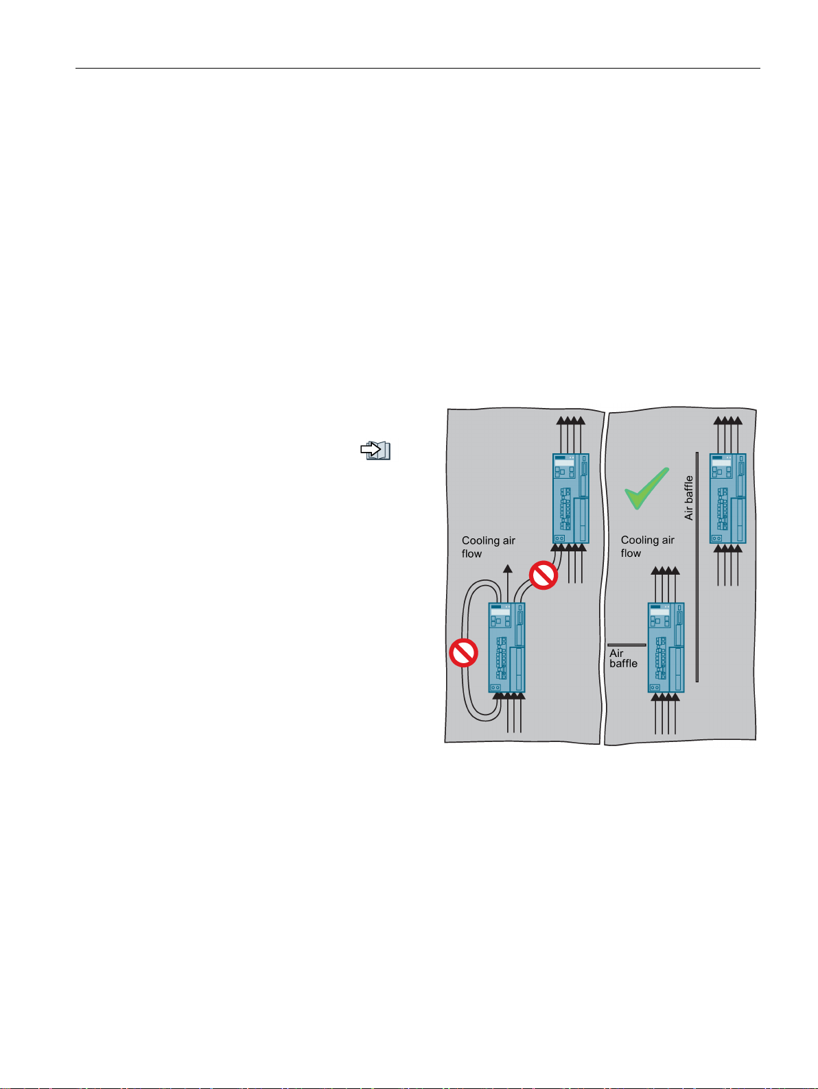
Measures in order to ensure that the components are adequately cooled
•
•
•
•
•
•
4.3 Power losses and air cooling requirements
To protect the components from overheating, the control cabinet requires a cooling air flow,
which depends on the power loss of the individual components.
Formula for calculating the cooling airflow:
● Power loss: Total of the power losses of the individual components.
● Δ T: Permissible temperature rise in the control cabinet
Add the power losses of the
individual components.
– Power Module data:
"Technical data (Page 65)".
– The Control Unit power loss is
less than 0.04 kW.
– Use the manufacturers data for
components, for example
reactors or filters
Calculate the air flow required,
using the formula above.
Ensure that the control cabinet is
appropriately ventilated and
equipped with suitable air filters.
Ensure that the components
maintain the specified clearances
with respect to one another.
Ensure that the components are provided with adequate cooling air through the cooling
openings.
Use the appropriate air barriers to prevent cooling air short circuits
Power Module PM240-2
Hardware Installation Manual, 01/2017, A5E33294624B AE
29

Installing/mounting
Power loss for Power Modules with push-through technology - PT devices
4.3 Power losses and air cooling requirements
When you use PT Power Modules, the majority of the power loss is dissipated through the
heatsink located outside the control cabinet.
The following losses occur in the cabinet when the device is operated with its rated data:
● FSA: 0.02 kW
● FSB: 0.045 kW
● FSC: 0.075 kW
Power Module PM240-2
30 Hardware Installation Manual, 01/2017, A5E33294624B AE
 Loading...