

Page 1
Operating Instructions
SIMOTICS CONNECT 400
Connectivity module
07/2019Edition
www.siemens.com/sidrive-iq
Page 2

Page 3

SIMOTICS CONNECT 400
Introduction
1
Operating Instructions
Safety instructions
Description
Preparations for use
Mounting and installation
Commissioning
Operation
Maintenance
2
3
4
5
6
7
8
Replacement parts
Disposal
Service & Support
Certificates and Licenses
9
10
A
B
07/2019
Page 4
Legal information
Warning notice system
This manual contains notices you have to observe in order to ensure your personal safety, as well as to prevent
damage to property. The notices referring to your personal safety are highlighted in the manual by a safety alert
symbol, notices referring only to property damage have no safety alert symbol. These notices shown below are
graded according to the degree of danger.
DANGER
indicates that death or severe personal injury will result if proper precautions are not taken.
WARNING
indicates that death or severe personal injury may result if proper precautions are not taken.
CAUTION
indicates that minor personal injury can result if proper precautions are not taken.
NOTICE
indicates that property damage can result if proper precautions are not taken.
If more than one degree of danger is present, the warning notice representing the highest degree of danger will be
used. A notice warning of injury to persons with a safety alert symbol may also include a warning relating to property
damage.
Qualified Personnel
The product/system described in this documentation may be operated only by personnel qualified for the specific
task in accordance with the relevant documentation, in particular its warning notices and safety instructions. Qualified
personnel are those who, based on their training and experience, are capable of identifying risks and avoiding
potential hazards when working with these products/systems.
Proper use of Siemens products
Note the following:
WARNING
Siemens products may only be used for the applications described in the catalog and in the relevant technical
documentation. If products and components from other manufacturers are used, these must be recommended or
approved by Siemens. Proper transport, storage, installation, assembly, commissioning, operation and
maintenance are required to ensure that the products operate safely and without any problems. The permissible
ambient conditions must be complied with. The information in the relevant documentation must be observed.
Trademarks
All names identified by ® are registered trademarks of Siemens AG. The remaining trademarks in this publication
may be trademarks whose use by third parties for their own purposes could violate the rights of the owner.
Disclaimer of Liability
We have reviewed the contents of this publication to ensure consistency with the hardware and software described.
Since variance cannot be precluded entirely, we cannot guarantee full consistency. However, the information in this
publication is reviewed regularly and any necessary corrections are included in subsequent editions.
Siemens AG
Digital Industries
Postfach 48 48
90026 NÜRNBERG
GERMANY
Ⓟ 08/2019 Subject to change
Copyright © Siemens AG 2019.
All rights reserved
Page 5

Table of contents
1 Introduction...................................................................................................................................................5
1.1 About these instructions...........................................................................................................5
1.1.1 Text format features .................................................................................................................5
1.1.2 Text references ........................................................................................................................5
1.2 Naming convention ..................................................................................................................5
2 Safety instructions ........................................................................................................................................7
2.1 General safety instructions.......................................................................................................7
2.2 Qualified personnel ..................................................................................................................7
2.3 Security information .................................................................................................................8
3 Description....................................................................................................................................................9
3.1 SIDRIVE IQ Fleet .....................................................................................................................9
3.2 "SIMOTICS CONNECT 400" connectivity module...................................................................9
3.3 Data security ..........................................................................................................................11
4 Preparations for use ...................................................................................................................................13
4.1 Visual inspection ....................................................................................................................13
4.2 Shipping and storage conditions ............................................................................................13
4.3 Requirements.........................................................................................................................13
5 Mounting and installation............................................................................................................................15
5.1 Connecting the battery ...........................................................................................................15
6 Commissioning ...........................................................................................................................................17
6.1 Requirements.........................................................................................................................17
6.2 Installing the "SIDRIVE IQ Config" application.......................................................................17
6.3 Establishing the connection to the connectivity module.........................................................17
6.4 Log in with the connectivity module .......................................................................................20
6.5 Making the necessary system settings ..................................................................................21
6.6 Setting up a WLAN connection ..............................................................................................22
6.7 Onboarding process using the "SIDRIVE IQ Config" application...........................................23
6.7.1 Starting the onboarding process via the "SIDRIVE IQ Config" application ............................24
6.7.2 Motor assignment...................................................................................................................24
6.7.3 Entering asset data ................................................................................................................25
6.7.4 Logging in to MindSphere ......................................................................................................26
6.7.5 Exiting the onboarding process via the "SIDRIVE IQ Config" application..............................27
SIMOTICS CONNECT 400
Operating Instructions, 07/2019 3
Page 6

Table of contents
7 Operation....................................................................................................................................................31
7.1 Identifying the connectivity module via the "SIDRIVE IQ Config" application ........................31
7.2 Changing measurement and synchronization intervals .........................................................31
7.3 Changing the user data of the connectivity module ...............................................................32
7.4 Adapting the location settings ................................................................................................33
8 Maintenance ...............................................................................................................................................35
8.1 Updating SIDRIVE IQ.............................................................................................................35
8.1.1 Updating the "SIDRIVE IQ Config" application ......................................................................35
8.1.2 Identifying the firmware version of the connectivity module...................................................35
8.1.3 Updating the connectivity module firmware ...........................................................................35
8.2 Restoring factory settings and resetting user data.................................................................37
8.3 Replacing the connectivity module.........................................................................................38
8.4 Replace the battery ................................................................................................................39
8.5 Mounting bracket fastening ....................................................................................................40
9 Replacement parts .....................................................................................................................................43
10 Disposal......................................................................................................................................................45
10.1 Disposing of the connectivity module.....................................................................................45
10.2 Disposing of the battery .........................................................................................................45
A Service & Support.......................................................................................................................................47
A.1 Siemens Industry Online Support ..........................................................................................47
B Certificates and Licenses ...........................................................................................................................49
B.1 Certificates, approvals, standards..........................................................................................49
B.2 Licenses .................................................................................................................................50
Index...........................................................................................................................................................51
SIMOTICS CONNECT 400
4 Operating Instructions, 07/2019
Page 7

Introduction
1.1 About these instructions
These instructions describe the connectivity module and provide you with information on how
to use the product – from installation through to maintenance.
Keep these instructions in a safe place for subsequent use.
Read these instructions before you use the connectivity module, and follow the instructions and
notes carefully. In this way you can ensure safe, problem-free operation and a long service life.
1.1.1 Text format features
Text format features
You can find the following text format features in these instructions:
1. Handling instructions are always formatted as a numbered list. Always perform the steps in
the order given.
1
● Lists are formatted as bulleted lists.
– Lists on the second level are hyphenated.
Note
The note provides you with additional information about the product itself, handling the product
- and the relevant documentation.
1.1.2 Text references
References to other texts always refer to the beginning of the chapter.
1.2 Naming convention
In this documentation, the generic term "Connectivity module" is used for the "SIMOTICS
CONNECT 400" product.
SIMOTICS CONNECT 400
Operating Instructions, 07/2019 5
Page 8

Introduction
1.2 Naming convention
SIMOTICS CONNECT 400
6 Operating Instructions, 07/2019
Page 9

Safety instructions
2.1 General safety instructions
The connectivity module conforms to the pertinent safety regulations according to IEC, VDE
and EN. If you have questions about the validity of the installation in the planned environment,
please contact your service representative.
Battery
WARNING
Danger of explosion and the release of harmful substances!
Improper handling of lithium batteries can cause them to explode.
Explosion of the batteries and the released pollutants can cause severe physical injury and/or
represent a serious health risk. Used batteries jeopardize the function of the device.
Note the following when handling lithium batteries:
● Replace the lithium battery only with an identical battery or types recommended by the
manufacturer.
● Do not throw the batteries into a fire.
● Do not solder at the cell body of the battery.
● Do not recharge the battery.
● Do not open the battery.
● Do not short-circuit the battery.
● Do not connect the battery with the incorrect polarity.
● Do not heat up the battery to over 100 °C.
● Protect the battery from direct solar radiation, humidity and condensation.
2
2.2 Qualified personnel
Only qualified personnel may perform work on the connectivity module. For the purpose of this
documentation, qualified personnel is taken to mean people who fulfill the following
requirements:
● Through appropriate training and experience, they are able to recognize and avoid risks and
potential dangers in their particular field of activity.
● Those responsible have instructed them to carry out the work.
SIMOTICS CONNECT 400
Operating Instructions, 07/2019 7
Page 10

Safety instructions
2.3 Security information
2.3 Security information
Siemens provides products and solutions with industrial security functions that support the
secure operation of plants, systems, machines and networks.
In order to protect plants, systems, machines and networks against cyber threats, it is
necessary to implement – and continuously maintain – a holistic, state-of-the-art industrial
security concept. Siemens’ products and solutions constitute one element of such a concept.
Customers are responsible for preventing unauthorized access to their plants, systems,
machines and networks. Such systems, machines and components should only be connected
to an enterprise network or the internet if and to the extent such a connection is necessary and
only when appropriate security measures (e.g. firewalls and/or network segmentation) are in
place.
For additional information on industrial security measures that may be implemented, please
visit
https://www.siemens.com/industrialsecurity (https://www.siemens.com/industrialsecurity).
Siemens’ products and solutions undergo continuous development to make them more secure.
Siemens strongly recommends that product updates are applied as soon as they are available
and that the latest product versions are used. Use of product versions that are no longer
supported, and failure to apply the latest updates may increase customer’s exposure to cyber
threats.
To stay informed about product updates, subscribe to the Siemens Industrial Security RSS
Feed under
https://www.siemens.com/industrialsecurity (https://www.siemens.com/industrialsecurity).
SIMOTICS CONNECT 400
8 Operating Instructions, 07/2019
Page 11
Description
&XVWRPHU
'DWD
WUDQVIHU
6,'5,9(,4)OHHW
,4
)OHHW
,4&RQ
ILJXUDWLRQ
6,'5,9(,4&RQILJ
3.1 SIDRIVE IQ Fleet
What is SIDRIVE IQ Fleet?
SIDRIVE IQ Fleet is the digital and Cloud-based solution for drive systems. The suite connects
networked drive components with the Cloud-based analytics in SIDRIVE IQ Fleet to improve
productivity, reliability and the service options available for drive components.
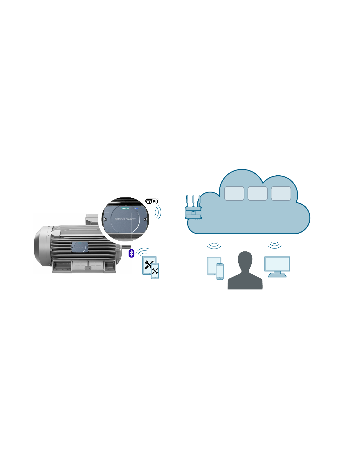
The following diagram provides you with a system overview of SIDRIVE IQ Fleet with the
SIMOTICS CONNECT 400 connectivity module:
3
Using the connectivity module, you can transfer data to SIDRIVE IQ where it is saved and
analyzed. Operating data can be displayed via SIDRIVE IQ Fleet. SIDRIVE IQ Fleet provides
users with data of the drive components and analysis results relating to their operation and
state. Further, it provides recommendations for preventive maintenance activities, for example.
Additional information
Additional information on the SIMOTICS CONNECT 400 connectivity module is provided in the
"SIMOTICS CONNECT 400" Operating Instructions.
3.2 "SIMOTICS CONNECT 400" connectivity module
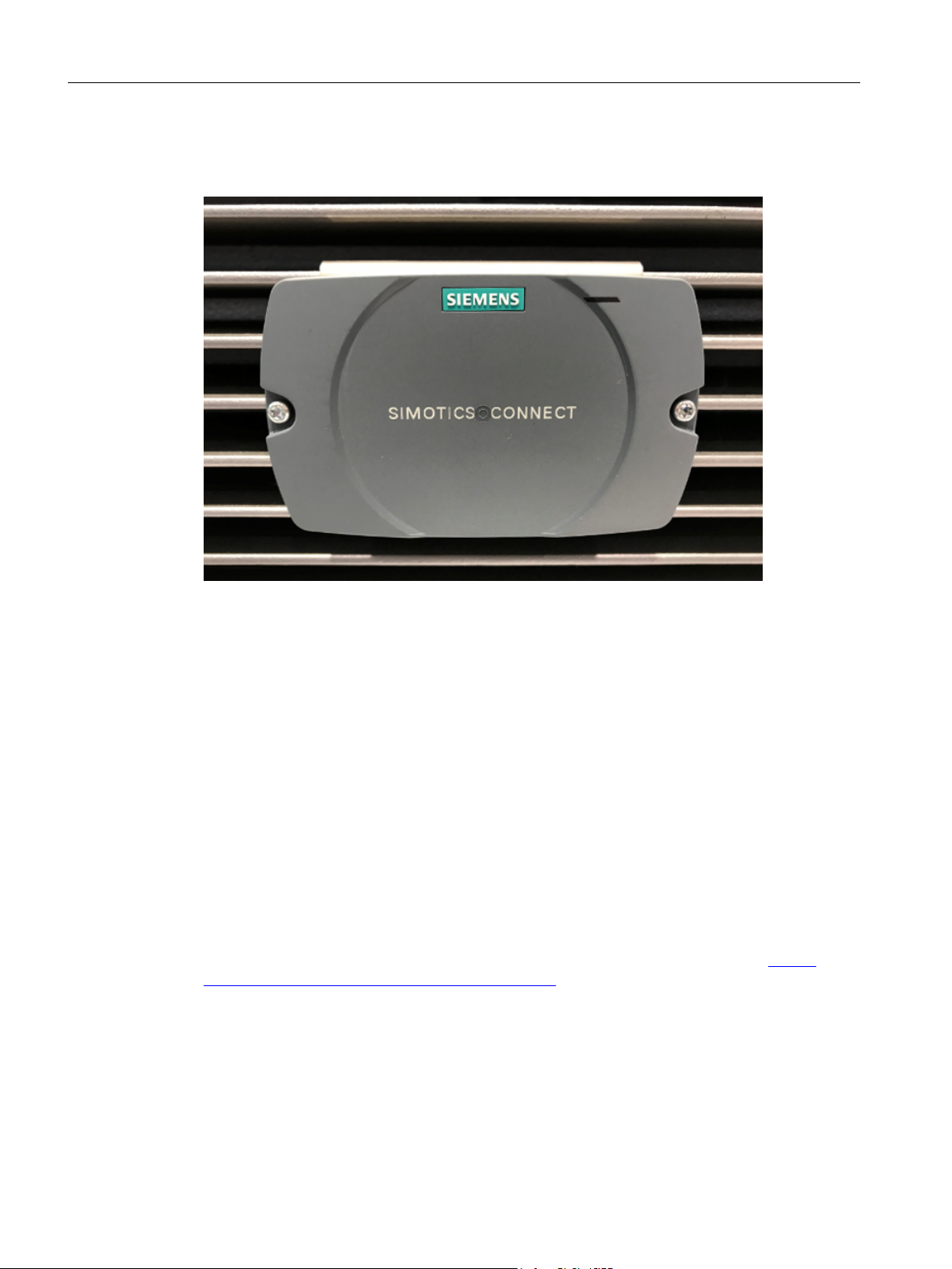
The connectivity module mounted on the motor captures important operating and status
information of the motor.
SIMOTICS CONNECT 400
Operating Instructions, 07/2019 9
Page 12
Description
3.2 "SIMOTICS CONNECT 400" connectivity module
The motor data that is captured is transferred to SIDRIVE IQ via a WLAN interface where it is
analyzed.
Components
The connectivity module encompasses the following components:
● Integrated sensors to measure the motor data
● Data memory
● Processor
● SPBTLE-RF bluetooth module for communication with a mobile device to configure the
● SN8000/8000UFL WLAN communication module to transfer the measured data to
● Lithium battery for the power supply
Additional information
Additional information about SIDRIVE IQ is provided in the "SIDRIVE IQ Suite" (https://
support.industry.siemens.com/cs/ww/en/ps/25291) Operating Instructions.
connectivity module
SIDRIVE IQ and update the firmware
SIMOTICS CONNECT 400
10 Operating Instructions, 07/2019
Page 13

3.3 Data security
The data is secured using the following mechanisms:
● Data is stored in the connectivity module until it is transferred to the Cloud
● Data is sent encrypted via a WLAN interface according to the "WPA2" standard
● Data is transmitted to the Cloud via a secure connection with TLS encryption
Description
3.3 Data security
SIMOTICS CONNECT 400
Operating Instructions, 07/2019 11
Page 14

Description
3.3 Data security
SIMOTICS CONNECT 400
12 Operating Instructions, 07/2019
Page 15
Preparations for use
4.1 Visual inspection
After mounting the motor, visually inspect the connectivity module for any damage.
Contact customer service (Page 47) if you identify any damage.
4.2 Shipping and storage conditions
WARNING
Transporting hazardous goods
The product is classified as a hazardous product according to UN 3091. The product contains
lithium-metal batteries. The batteries contain approximately 2.6 g of lithium. When the product
is transported, it is not permissible that the battery connector is in contact with the electronics
module.
Carefully comply with the regulations that are applicable for transport.
4
NOTICE
Damage to the connectivity module due to external influences
The connectivity module is mounted onto the motor in the factory before the motor is shipped.
During transport, storage and when the motor is operated, the connectivity module can be
damaged due to external influences.
Do not damage the connectivity module while the motor is being transported, stored and
operated. It is not permissible that the connectivity module is subject to mechanical loads and
stress.
4.3 Requirements
Mobile device for the "SIDRIVE IQ Config" application
To set up the connectivity module, install the "SIDRIVE IQ Config" application on a mobile
device. The mobile device must satisfy the following requirements:
● "Android" operating system with Version V5.0 or later
● Functioning Internet connection
SIMOTICS CONNECT 400
Operating Instructions, 07/2019 13
Page 16

Preparations for use
4.3 Requirements
Download the "SIDRIVE IQ Config" application from the "Google Play Store" (Page 17).
Mobile device with Bluetooth
The mobile device must have an integrated Bluetooth interface that supports the Bluetooth Low
Energy V4.1 standard - or a later standard.
WLAN connection
The current version of the connectivity module does not support a proxy server configuration.
Use a direct Internet connection.
The connectivity module encrypts your data according to the "WPA2" security standard. For
data transfer, the connectivity module supports WLAN connections with a frequency of 2.4 GHz
and the Wi-Fi 802.11b/g/n standard. Only WLAN passwords with a maximum length of 32
characters are supported.
Ports that are used
Release the following ports used by SIMOTICS CONNECT 400 to allow an Internet connection
to be established:
● Secured data exchange with SIDRIVE IQ: TCP port: 443
● Name resolution via DNS: TCP port: 53 UDP port: 53
● Time synchronization via NTP: UDP port: 123
● IP address assigned via DHCP: TCP port: 67, 68 UDP port: 67, 68
● The mobile device firmware is updated in the same WLAN network: TCP port: 80
SIMOTICS CONNECT 400
14 Operating Instructions, 07/2019
Page 17
Mounting and installation
NOTICE
SIMOTICS CONNECT 400 housing with an IP54 degree of protection
If the ambient conditions according to IP54 cannot be ensured at the installation location – or
if a higher degree of protection is required – then the user must apply additional measures to
ensure safe and reliable operation.
The connectivity module is mounted in the factory. Mounting or removal is only necessary if the
connectivity module has to be replaced (Page 43).
5.1 Connecting the battery
The battery is installed in the factory, but it is not connected. Connect the battery before
commissioning the device.
Mounting elements
5
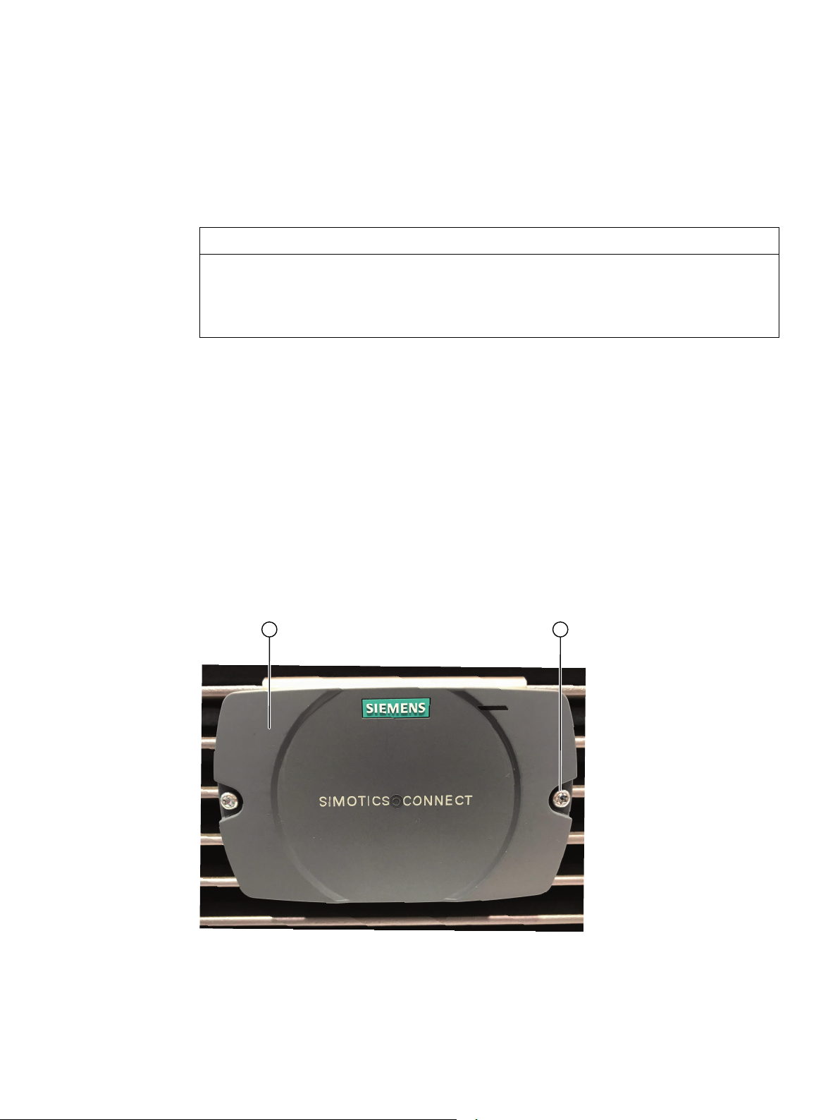
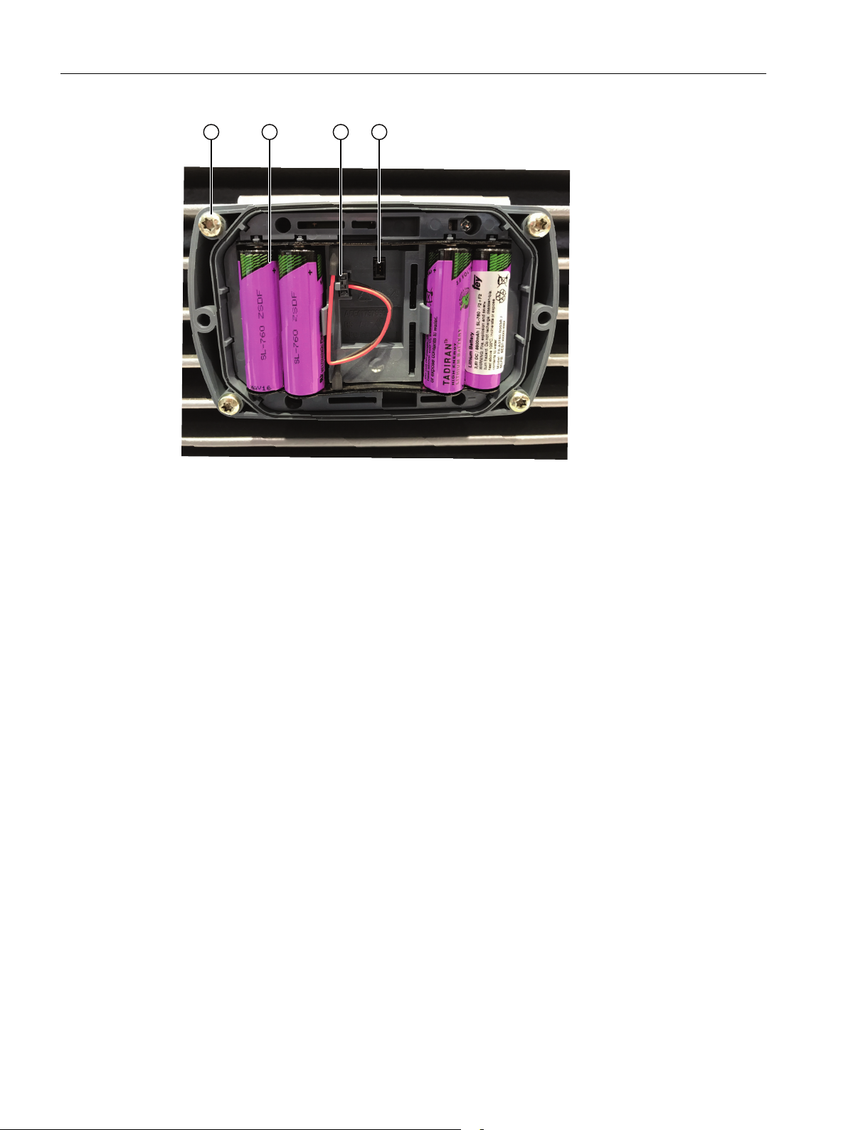
An overview of the relevant mounting elements of the connectivity module is shown in the
closed and open states in the following diagrams:
① Front cover
② Screws to fasten the cover
SIMOTICS CONNECT 400
Operating Instructions, 07/2019 15
Page 18
Mounting and installation
5.1 Connecting the battery
① Fastening screws
② Battery
③ Battery connector
④ Socket
Requirements
● Visually inspect the battery for any damage.
● You require a Torx® T 20 screwdriver.
Procedure
1. At the front cover of the connectivity module release the 2 fastening screws.
2. Remove the front cover.
3. Insert the battery connector by gently pressing on the socket provided. It is not possible to
4. Reattach the front cover. Carefully ensure that the cover is precisely in the correct position.
5. Tighten the two screws by hand. The thread can be damaged if too much force is applied.
Do not completely turn the screws from the cover so that the screws are not lost.
incorrectly insert the connector as a result of the connector coding used.
The connectivity module LED lights for approx. 20-30 seconds for a battery test.
SIMOTICS CONNECT 400
16 Operating Instructions, 07/2019
Page 19

Commissioning
6.1 Requirements
● The connectivity module battery is now connected.
● The Bluetooth interface of the mobile device with Bluetooth Low Energy V4.1 or newer is
activated.
● The function to determine position data is activated.
● The mobile device has an Internet connection via WLAN or GSM/LTE
● There is a WLAN access point to connect the connectivity module with the Internet.
● You have the valid access data for SIDRIVE IQ.
6.2 Installing the "SIDRIVE IQ Config" application
1. Open the Google Play Store.
2. Install the Siemens "SIDRIVE IQ Config" application.
6
The "SIDRIVE IQ Config" application requires authorization to access the following:
– Bluetooth interface
– Localization data (to determine the asset location)
– Camera (to scan the motor data matrix code)
– Memory (to update the connectivity module firmware)
6.3 Establishing the connection to the connectivity module
Start the "SIDRIVE IQ Config" application on your mobile device. The application automatically
activates the Bluetooth interface of your mobile device, and shows active connectivity modules
in a range of approximately 10 m. The BLE name set in the factory is "SC 400". You can change
the name at a later point in time.
SIMOTICS CONNECT 400
Operating Instructions, 07/2019 17
Page 20

Commissioning
6.3 Establishing the connection to the connectivity module
Use the "Identify" function to check that you are connected with the required connectivity
module (Page 31).
Note
Length limitations of the BLE name
The BLE name is used to simply identify the device via Bluetooth. The length of the name is
restricted to 7 characters.
SIMOTICS CONNECT 400
18 Operating Instructions, 07/2019
Page 21
"Device overview" page
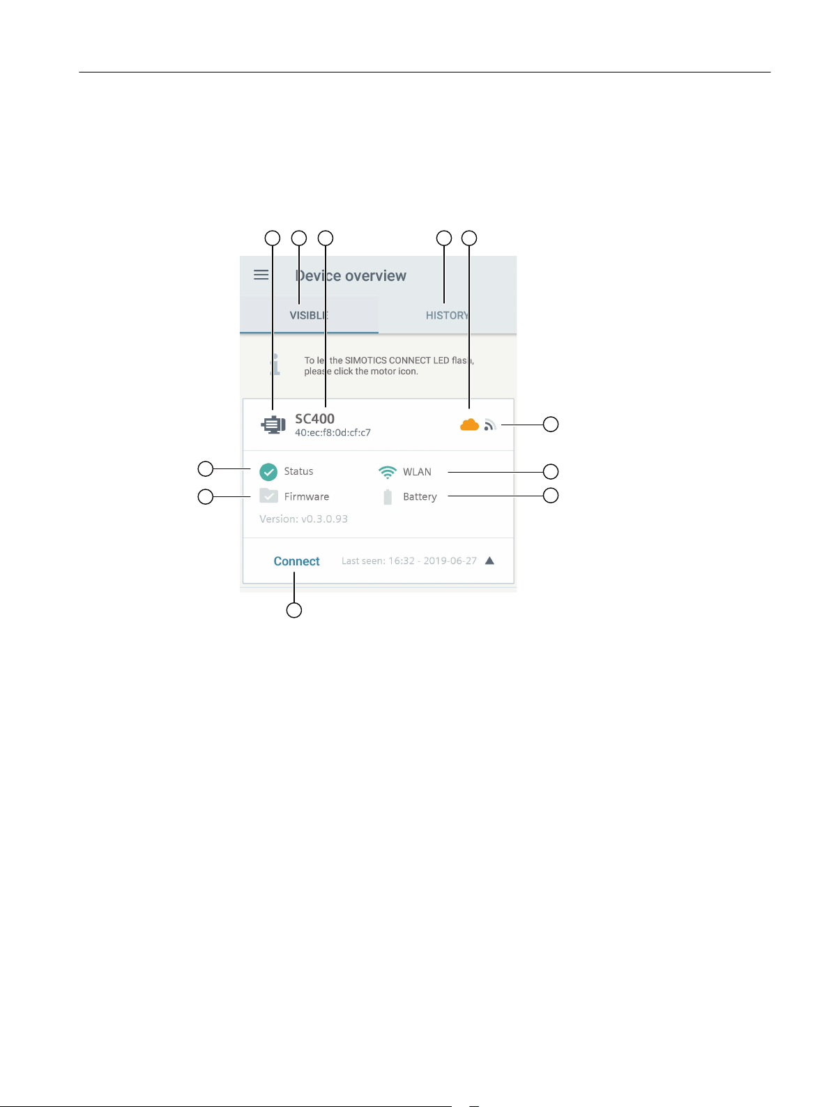
When the "SIDRIVE IQ Config" application starts, as default, you see a list of all of the currently
visible assets on the "Device overview" page. You can also display all of the assets visible in
the history. A list entry contains the information about an asset. The following diagram explains
the pictograms in a list entry.
Commissioning
6.3 Establishing the connection to the connectivity module
① Motor symbol to identify an asset
② You see all of the currently visible assets under this tab.
③ BLE name and Mac address of the currently selected connectivity module
④ Under this tab, you see all of the assets visible in the past.
⑤ Connection status of the connectivity module to SIDRIVE IQ (onboarding status)
● "Green" status: Connected
● "Orange" status: Not connected
● "Red" status: Connected, however, there is a connection error
⑥ Bluetooth interface signal strength display
⑦ WLAN configuration status of the connectivity module:
● "Green" status: WLAN configured and operating correctly
● "Red" status: WLAN not configured or has a fault
⑧ Battery state of the connectivity module (the current version does not support this display.)
⑨ "Connect" button to establish a connection to the connectivity module
⑩ Update status of the connectivity module firmware (the current version does not support this
display.)
⑪ Status of the connectivity module
SIMOTICS CONNECT 400
Operating Instructions, 07/2019 19
Page 22

Commissioning
6.4 Log in with the connectivity module
Procedure
1. Open the "SIDRIVE IQ Config" application.
2. Open the overview page.
3. Select an asset from the "Visible" tab.
4. Tap on "Connect".
6.4 Log in with the connectivity module
After a connection has been established from the "SIDRIVE IQ Config" application to the
connectivity module, a window is displayed where you can enter the login data for the
connectivity module. If you do not login, then you will only be able to select a limited number of
functions.
Menus and functions without logging in
You do not need to login to the connectivity module for all menus and functions. You can view
or use the following menus and functions without logging in:
● "Login" menu
● "SIMOTICS CONNECT" menu
Functions "Identification" and "Reset user credentials" can be selected.
● "Settings" menu:
You are automatically routed to the "System settings" submenu. You can view the settings
- however, you cannot change them.
Factory settings for logging in
The factory settings for logging in are as follows:
● User name ("admin")
● The password (comprises the last 6 digits of the serial number as stamped on the
connectivity module nameplate)
After logging in for the first time, change the user name and the password of the "SIDRIVE IQ
Config" application in menu "Settings > User".
SIMOTICS CONNECT 400
20 Operating Instructions, 07/2019
Page 23
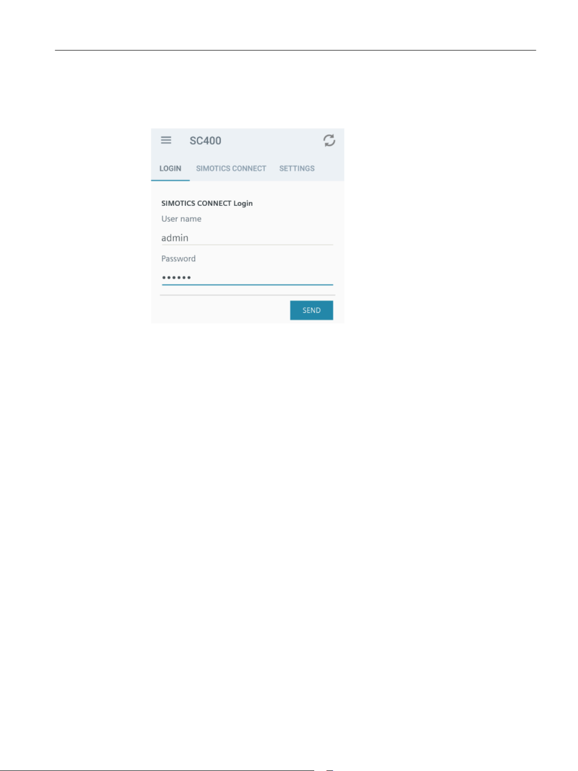
Procedure
Commissioning
6.5 Making the necessary system settings
1. Tap on "Connect" in the list entry for an asset.
A window is displayed where you can enter the login data for the connectivity module.
2. Enter the user name and password. At the end of your entry ensure that no spaces are
automatically added.
3. Tap on "Send".
The appropriate data is exchanged. You now have full access to all menus and functions of
the connectivity module.
6.5 Making the necessary system settings
You must make the following settings when commissioning the connectivity module:
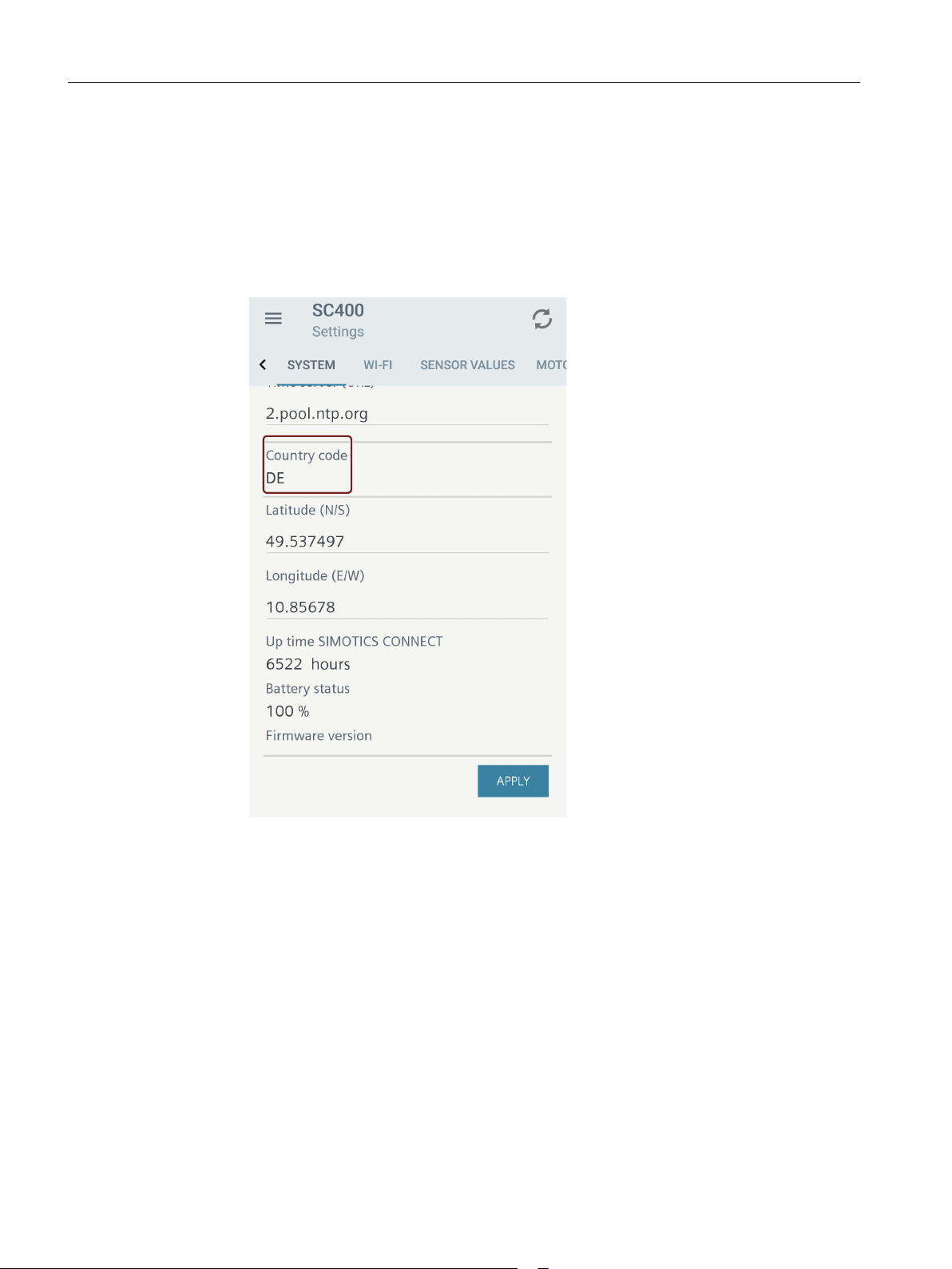
● Country code: Ensures that the WLAN module functions in the particular country. The
country code is not initialized in the factory state. You must set the country code so that you
can establish the WLAN connection.
● NTP server (time server): Optionally, you can set another NTP server, e.g. a server within
your own network.
Procedure
1. Select the "Settings" menu.
2. Select the "System" submenu.
3. If required, set another "time server" (URL).
SIMOTICS CONNECT 400
Operating Instructions, 07/2019 21
Page 24
Commissioning
6.6 Setting up a WLAN connection
4. Apply one of the following steps in order to set the country code:
– Automatically determining the country code:
Briefly press on the "Country code" field. The country is automatically determined and is
shown as two-letter abbreviation (for example, DE for Germany).
– Manually determining the country code:
Press on the "Country code" field for a longer period of time. A country drop-down list
opens. Manually select the country from the list.
5. Confirm your changes by clicking on "Apply".
6.6 Setting up a WLAN connection
Supported WLAN networks
The current version of the connectivity module does not support a proxy server configuration.
The connectivity module encrypts your data according to the "WPA2" security standard. For
data transfer, the connectivity module supports WLAN connections with a frequency of 2.4 GHz
and the Wi-Fi standard 802.11b/g/n.
SIMOTICS CONNECT 400
22 Operating Instructions, 07/2019
Page 25
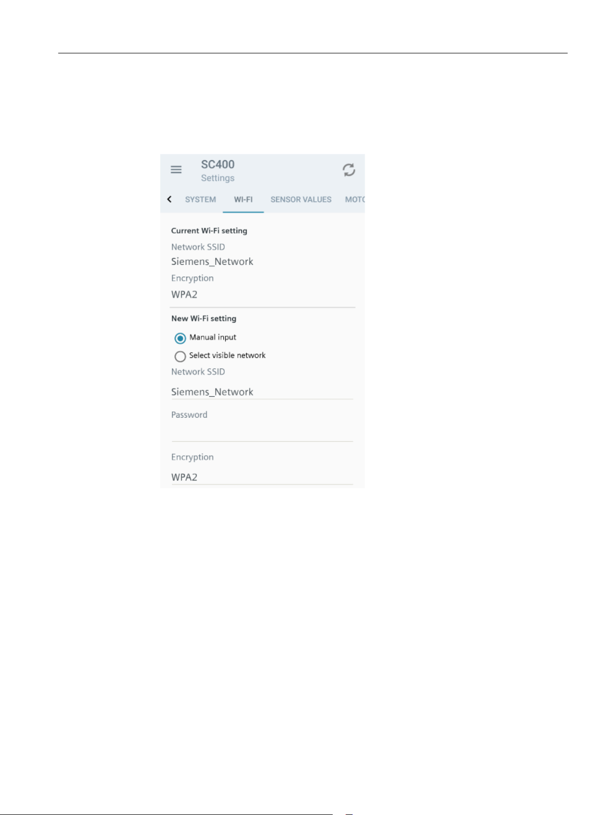
Procedure
Commissioning
6.7 Onboarding process using the "SIDRIVE IQ Config" application
1. Select the "Settings" menu.
2. Select submenu "WI-FI". The current settings are shown in submenu "WI-FI", and provide
you the option of selecting other Wi-Fi settings.
3. Configure the WI-FI settings:
– Activate the "Manual input" option to manually set the SSID network.
– Activate the "Select visible networks" option to select the required network from the list
of visible networks. A list of all of the detected WLAN networks is displayed in the
selection menu.
4. Enter the WLAN password. The WLAN password must not exceed a maximum length of 32
characters.
5. Confirm your entries by clicking on "Send".
6.7 Onboarding process using the "SIDRIVE IQ Config" application
Onboarding involves the connection and registration process, with all of its associated settings,
from the connectivity module to SIDRIVE IQ Fleet.
SIMOTICS CONNECT 400
Operating Instructions, 07/2019 23
Page 26
Commissioning
6.7 Onboarding process using the "SIDRIVE IQ Config" application
6.7.1 Starting the onboarding process via the "SIDRIVE IQ Config" application
Requirement
You have logged onto the connectivity module (Page 20).
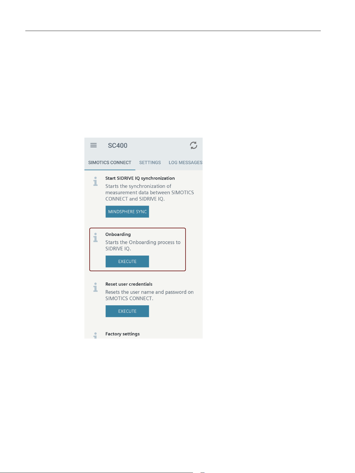
Procedure
1. Select menu "SIMOTICS CONNECT" with the most important basic functions.
2. In the "Onboarding" entry, tap on "Execute".
6.7.2 Motor assignment
To obtain the complete functionality, the connectivity module must be correctly assigned to the
motor. For connectivity modules mounted in the factory, the motor serial number is already set
in the module and you can skip the "Motor assignment" step.
If the connectivity module is replaced by another module, then you must reassign the motor
serial number. This operation then updates the associated motor information. Only assign the
SIMOTICS CONNECT 400
24 Operating Instructions, 07/2019
Page 27
connectivity module to the motor on which it is mounted. In step "Enter asset data" (Page 25),
select between the following options:
● Motor assignment by manually entering the serial number
Manually enter the motor serial number in the "SIDRIVE IQ Config" application during the
onboarding process. Based on the serial number, the electrical parameters of the motor are
copied out of the digital twin saved in the Cloud and transferred into the connectivity module.
● Motor assignment using the motor data matrix code
If the motor is equipped with a scannable code, you can identify the motor to which you have
local access. The serial number is read out by scanning it. Scan the motor data matrix code
by tapping on .
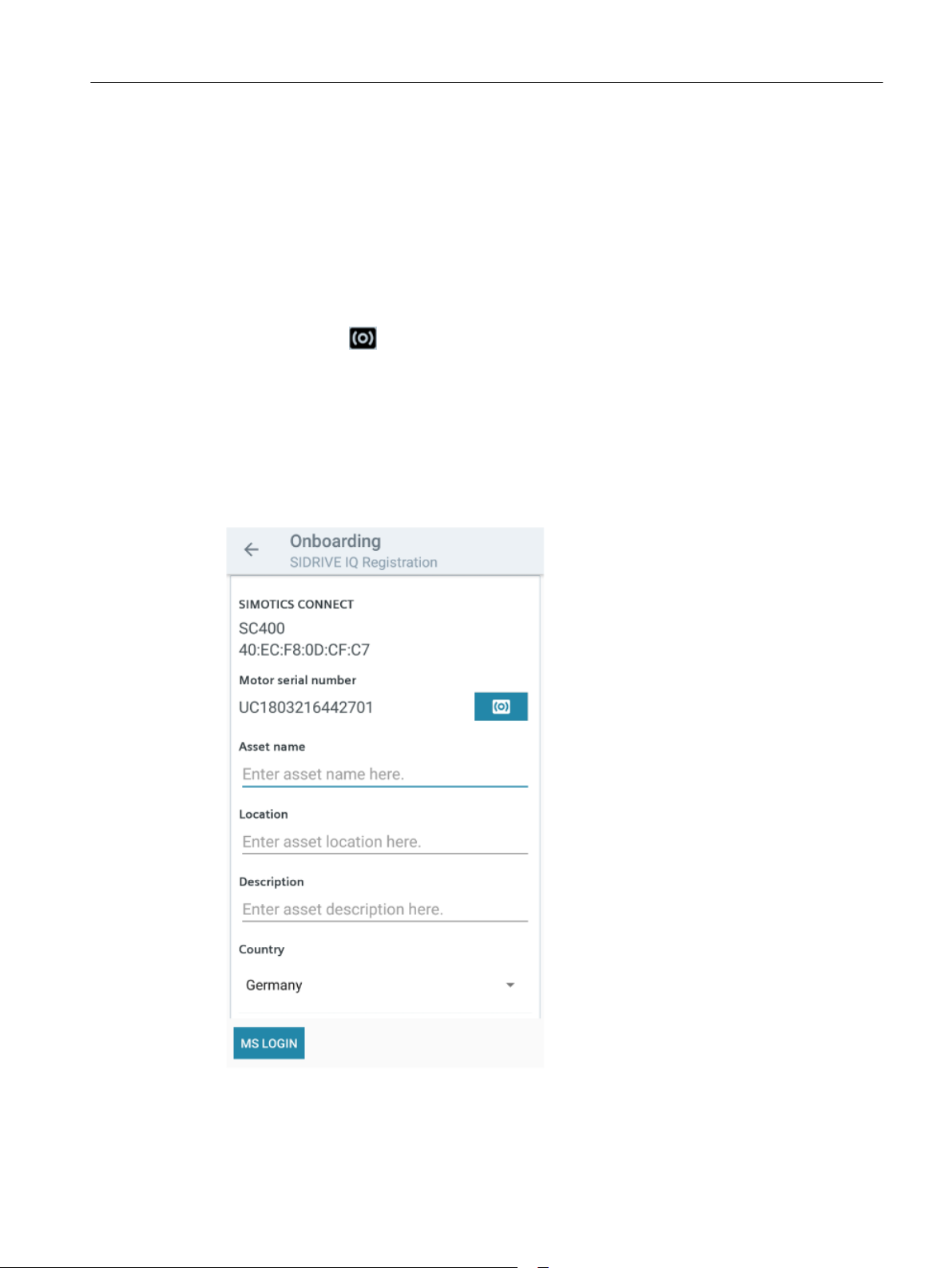
6.7.3 Entering asset data
Once you have started the onboarding process, you must complete the associated asset data.
The MindSphere URL and the path for registration are already preset as default setting.
The following diagram shows the dialog to enter asset data:
Commissioning
6.7 Onboarding process using the "SIDRIVE IQ Config" application
SIMOTICS CONNECT 400
Operating Instructions, 07/2019 25
Page 28
Commissioning
6.7 Onboarding process using the "SIDRIVE IQ Config" application
Procedure
1. Enter the asset data. The following fields are mandatory:
– Asset name: The asset name must be unique. It is not permissible that you reuse an
asset name that has already been used.
– Location
– Description
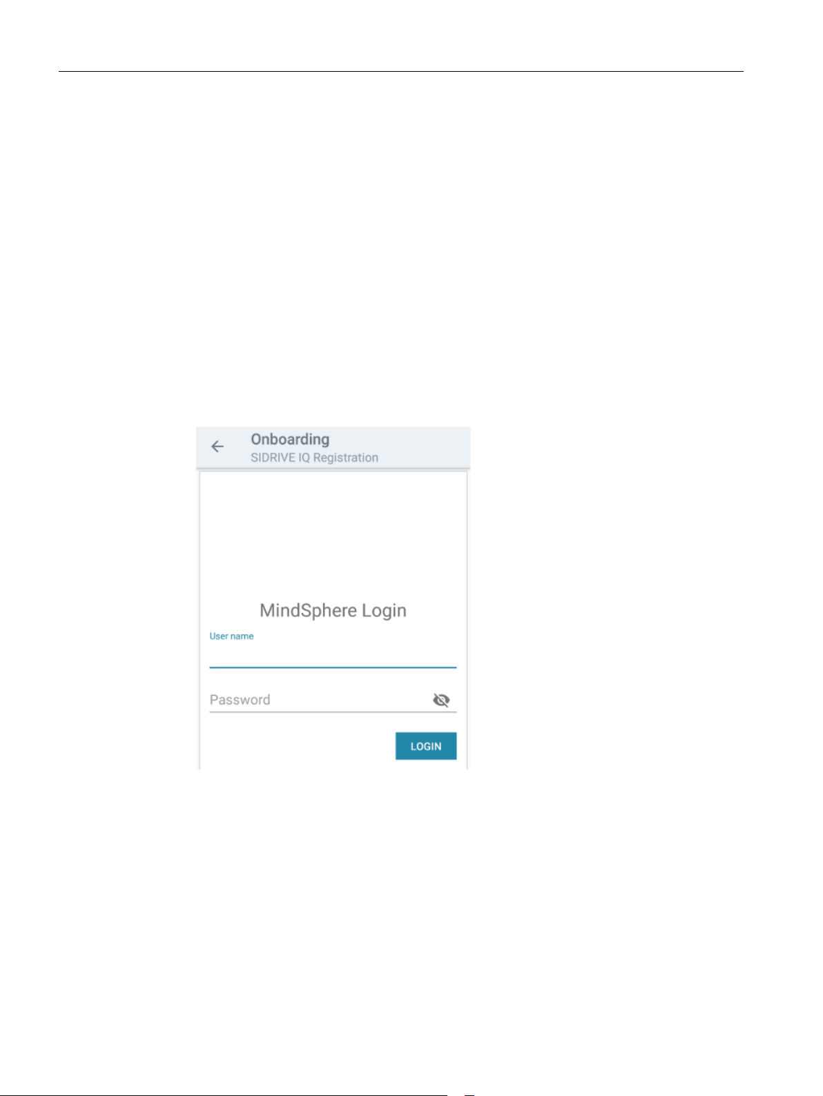
2. Make your entry using the "MS LOGIN" button (MindSphere login).
The asset data have been transferred. The dialog to log in to MindSphere (Page 26) is
displayed.
6.7.4 Logging in to MindSphere
1. To carry out the onboarding procedure, log in to MindSphere using your SIDRIVE IQ login
data. At the end of your entry ensure that no spaces are automatically added.
2. Confirm the entry using the "Login" button. The dialog to exit the onboarding process
(Page 27) is displayed.
While you are logged in to the "SIDRIVE IQ Config" application, the SIDRIVE IQ login data
is saved for logging in to MindSphere for further onboarding processes. If you close the
application, then you are automatically logged out of MindSphere.
SIMOTICS CONNECT 400
26 Operating Instructions, 07/2019
Page 29
Commissioning
6.7 Onboarding process using the "SIDRIVE IQ Config" application
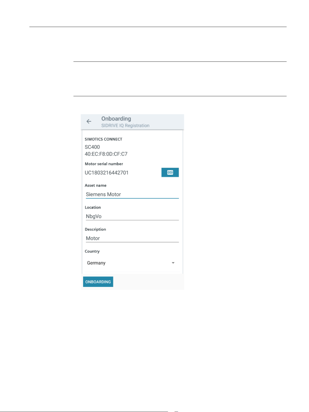
6.7.5 Exiting the onboarding process via the "SIDRIVE IQ Config" application
Note
Settings cannot be subsequently changed
Carefully select the following settings. Once selected, you cannot change the settings.
Repeat the onboarding process if you have selected an incorrect setting.
1. Check the asset data.
2. Confirm the onboarding process by clicking on "Onboarding". A dialog box to select the
operating mode opens.
SIMOTICS CONNECT 400
Operating Instructions, 07/2019 27
Page 30
Commissioning
6.7 Onboarding process using the "SIDRIVE IQ Config" application
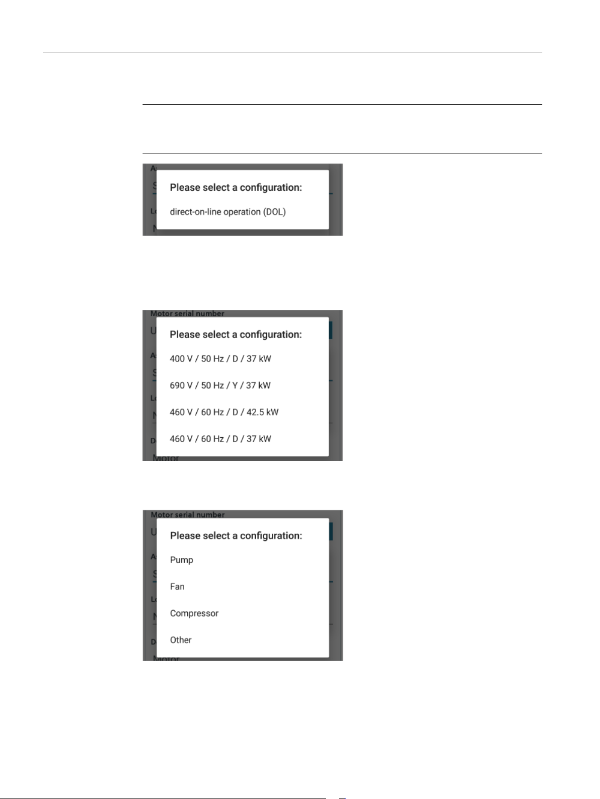
3. Select the operating mode: line operation: direct-on-line operation (DOL)
Note
Converter operation is not supported (VSD operation)
The actual version does not support motors controlled from a converter.
A dialog box to select the rated motor data opens. The electrical parameters saved in
SIDRIVE IQ are loaded to the connectivity module.
4. If there are several parameter sets in the rated motor data, select the parameter set that
corresponds to the connection conditions for your particular motor.
A dialog box to select the application opens.
5. Select the application.
SIMOTICS CONNECT 400
28 Operating Instructions, 07/2019
Page 31

Result
Commissioning
6.7 Onboarding process using the "SIDRIVE IQ Config" application
The next step of the onboarding process is automatically performed. This procedure takes
about 1 minute. During this procedure, the "SIDRIVE IQ Config" application outputs messages
about the actions currently being performed. You receive confirmation once the onboarding
process has been successfully completed. The connectivity module starts to capture data, and
transfers this data at the preset intervals.
The connectivity module automatically starts the calibration procedure at the motor. It requires
10 measuring cycles with the motor in the RUN state and 10 measuring cycles with the motor
in the OFF state. Precise data is only displayed in the SIDRIVE IQ once the calibration
procedure has been completed.
● Value "0": Motor off (OFF), sensor calibrated
● Value "1": Motor state not defined, sensor not calibrated
● Value "3": Motor on (RUN), sensor calibrated
SIMOTICS CONNECT 400
Operating Instructions, 07/2019 29
Page 32

Commissioning
6.7 Onboarding process using the "SIDRIVE IQ Config" application
SIMOTICS CONNECT 400
30 Operating Instructions, 07/2019
Page 33

Operation
7.1 Identifying the connectivity module via the "SIDRIVE IQ Config" application
Every connectivity module has a blue LED in the front cover that is used for identification. Use
the "Identify" function to check that you are connected with the required connectivity module.
Procedure
1. Open the "SIDRIVE IQ Config" application.
2. Open the overview page.
3. Select an asset from the "Visible" tab.
4. Tap on the motor symbol in the list entry.
The connectivity module LED flashes. The firmware version is read out and displayed.
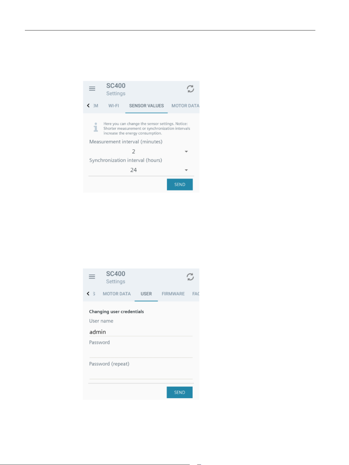
7.2 Changing measurement and synchronization intervals
The following intervals are preset in the factory:
7
● 1 minute - measurement interval for temperature, vibration, rotational frequency, operating
state
You can change these settings within a specified range.
● 3 minutes - calculation interval for speed, torque and energy usage
This setting is always three times the short measurement interval that has been set.
● 24 hours – interval when the saved data is transferred to SIDRIVE IQ
You can change these settings within a specified range of between 1 and 48 hours.
Note
Effects that influence the battery service life
Shorter intervals result in a shorter battery lifetime.
SIMOTICS CONNECT 400
Operating Instructions, 07/2019 31
Page 34
Operation
7.3 Changing the user data of the connectivity module
Procedure
1. Select the "Settings" menu.
2. Select the "Sensor values" submenu.
3. Change the measurement interval.
4. Change the synchronization interval.
7.3 Changing the user data of the connectivity module
1. Select the "Settings" menu.
2. Select the "User" submenu.
3. Change the user names. The user name name may not exceed 20 characters.
SIMOTICS CONNECT 400
32 Operating Instructions, 07/2019
Page 35

4. Change the password in the "Password" field. The password must meet the following
requirements:
– Minimum of 6 characters
– Maximum of 20 characters
– At least one uppercase letter (A-Z)
– At least one lowercase letter (a-z)
– At least one number (0-9)
– The following special characters are permitted: Hyphens (-) and underscores (_) are
allowed.
5. Enter the new password again in the "Password (repeat)" field.
6. Confirm your changes by clicking on "Send".
The user data are changed.
7.4 Adapting the location settings
Operation
7.4 Adapting the location settings
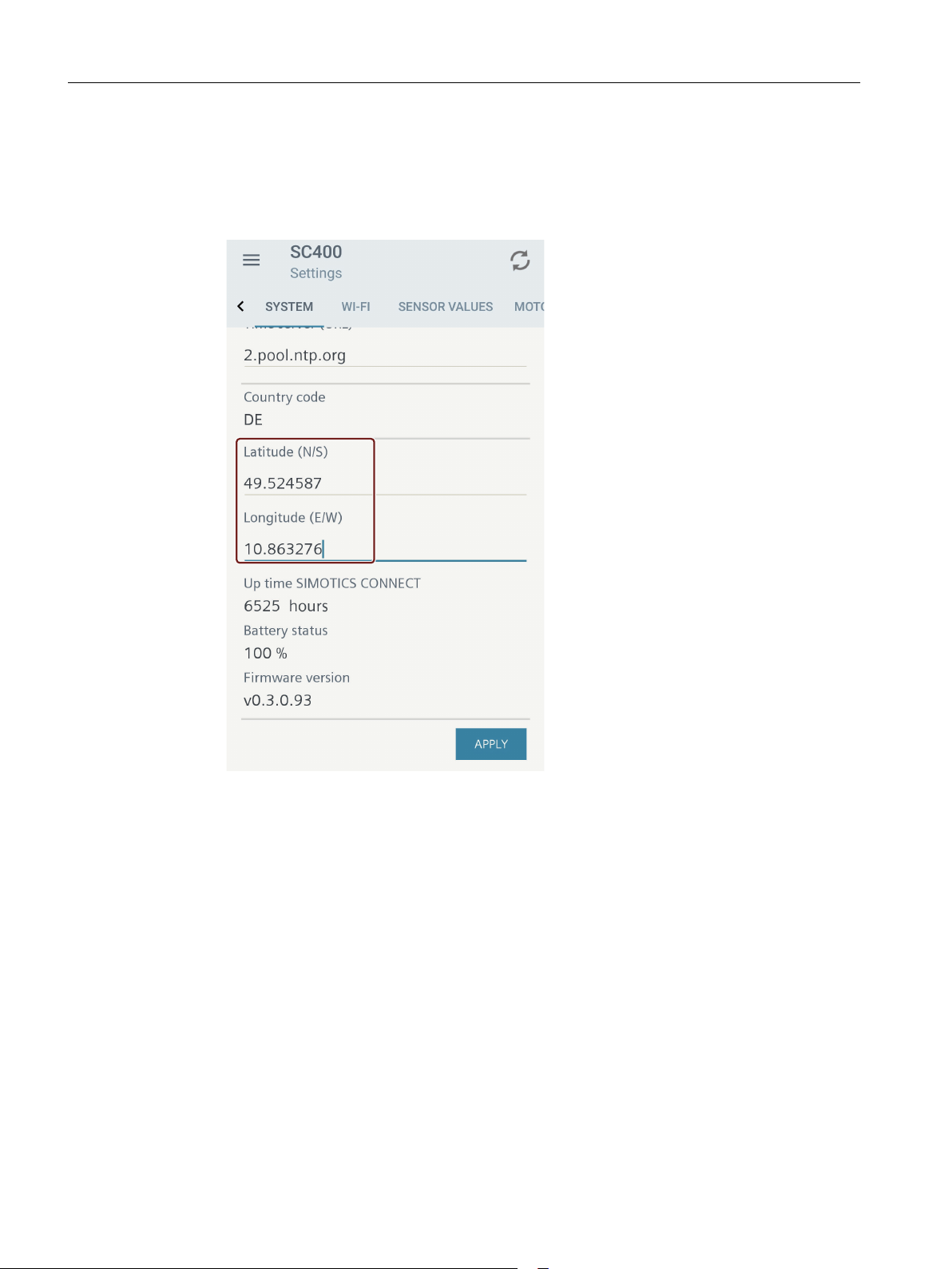
While commissioning the connectivity module, the location of your asset is determined using
the site determination of your mobile device. If the location of your asset changes after
commissioning the connectivity module, then appropriately change the location setting of your
asset.
SIMOTICS CONNECT 400
Operating Instructions, 07/2019 33
Page 36
Operation
7.4 Adapting the location settings
Procedure
1. Select the "Settings" menu.
2. Select the "System" submenu. The longitude and latitude degrees are displayed as decimal
degrees for the current location.
3. Change the values.
4. Confirm your changes by clicking on "Apply".
The location settings are changed.
SIMOTICS CONNECT 400
34 Operating Instructions, 07/2019
Page 37

Maintenance
8.1 Updating SIDRIVE IQ
Software updates are made available at regular intervals to keep the functionality of the
"SIDRIVE IQ Config" application up-to-date and to implement new functions.
8.1.1 Updating the "SIDRIVE IQ Config" application
1. Update the "SIDRIVE IQ Config" application via the Google Play Store.
2. To do this, activate the "Automatic update to" or "Notification via App updates" function.
8.1.2 Identifying the firmware version of the connectivity module
1. Select the "Settings" menu.
2. Select the "System" submenu.
3. Scroll to the end of the "System" submenu.
The installed firmware version is displayed.
8
8.1.3 Updating the connectivity module firmware
Firmware updates are available (https://support.industry.siemens.com/cs/de/en/ps/25522/dl)
to keep the connectivity module firmware up-to-date, and to implement new functions. Update
the firmware using the "SIDRIVE IQ Config" application.
Requirements
● On your mobile device, issue permission to access the "SIDRIVE IQ Config" application
memory.
● The connectivity module must be located in the same WLAN network as presently being
used by the mobile device.
SIMOTICS CONNECT 400
Operating Instructions, 07/2019 35
Page 38
Maintenance
8.1 Updating SIDRIVE IQ
Procedure
NOTICE
Damage to the connectivity module by disconnecting the battery
If the battery is disconnected while the firmware is being updated, then this can result in
unrepairable damage to the connectivity module.
Do not disconnect the battery while the firmware is being updated.
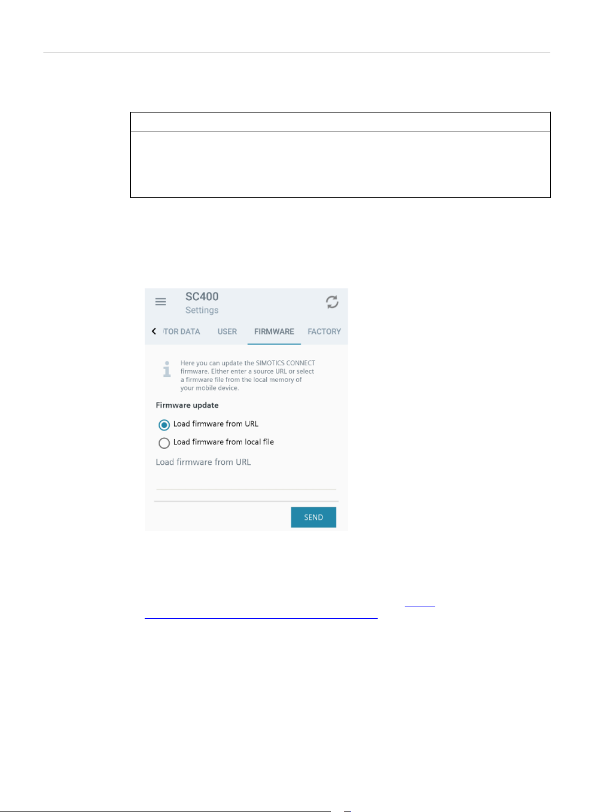
1. Activate the WLAN on your mobile device.
2. Open the "SIDRIVE IQ Config" application.
3. Select the "Settings" menu.
4. Select the "Firmware" submenu.
5. Update the firmware using one of the following options:
– Via an Internet address (URL)
– Load from a file that is resident on your mobile device
Siemens provides the firmware in the form of a ".bin" file (https://
support.industry.siemens.com/cs/de/en/ps/25522/dl).
6. Tap on "Send". A progress bar is displayed while the firmware file is being transferred.
Result
After transferring the firmware file, a security check is performed and then the firmware is
updated. This procedure takes about 1 to 2 minutes. During this time, the LED on the front of
the connectivity module first flashes slowly – and then faster. The LED goes dark after the
firmware has been updated.
SIMOTICS CONNECT 400
36 Operating Instructions, 07/2019
Page 39
8.2 Restoring factory settings and resetting user data
The connectivity module automatically restarts after the firmware has been successfully
updated. The Bluetooth connection to the mobile device is reset. In rare cases it is possible that
an error message is displayed on the mobile device: for example, "BLE error".
8.2 Restoring factory settings and resetting user data
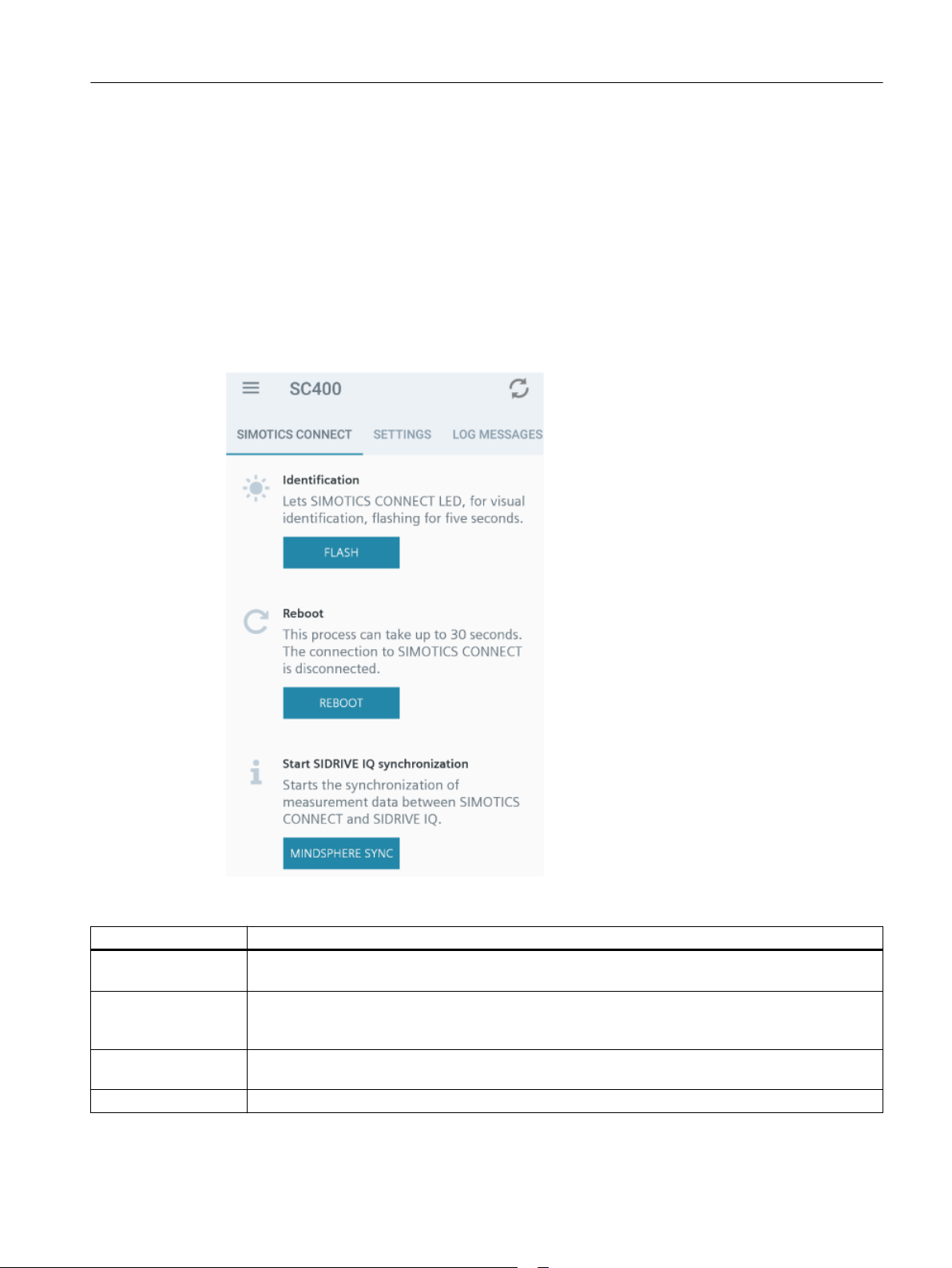
You can find the most important basic functions of the connectivity module in the "SIMOTICS
CONNECT" menu of the "SIDRIVE IQ Config" application.
Maintenance
An overview of all of the basic functions is shown in the following table:
Function Description
Identification Helps you to visually identify the currently connected connectivity module. The connectivity module
LED flashes for five seconds.
Restart The connectivity module restarts. The connectivity module is disconnected. Measurement data that
have still not been transferred to SIDRIVE IQ are lost. To avoid losing any data, before you restart
the connectivity module, run the "Start MindSphere synchronization" function.
Starting MindSphere
synchronization
Onboarding Starts the onboarding process to SIDRIVE IQ.
SIMOTICS CONNECT 400
Operating Instructions, 07/2019 37
This starts transferring measurement data from the connectivity module memory to SIDRIVE IQ.
Page 40
Maintenance
8.3 Replacing the connectivity module
Function Description
Offboarding Deletes all onboarding information in the connectivity module. After offboarding, it is no longer
possible to transfer measurement data to SIDRIVE IQ. To transfer data, start a new onboarding
process.
Offboarding is a precondition for a new onboarding process to SIDRIVE IQ.
Reset user credentials Resets the user name and the connectivity module password to the factory settings.
Factory settings Resets the connectivity module to the factory settings. The user data are reset to the factory settings.
All of the saved motor data and onboard information are lost.
8.3 Replacing the connectivity module
Connectivity module as replacement part
You can order the connectivity module as replacement part (Page 43). The battery is not
connected and it has no motor parameters. You must configure the device from new.
Procedure
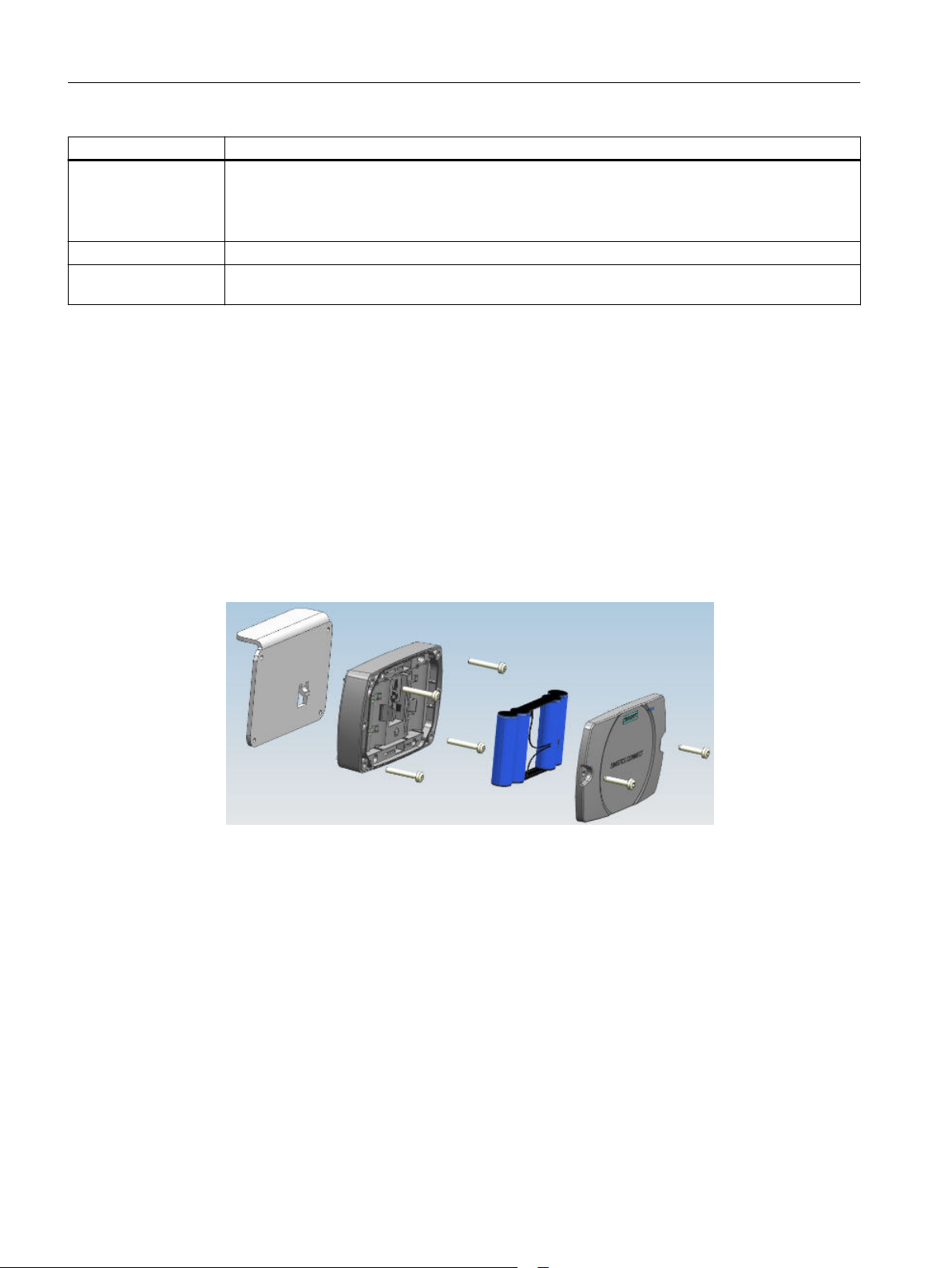
1. At the front cover release the two central fastening screws.
Do not completely turn the screws from the cover so that the screws are not lost.
2. Remove the front cover.
3. Withdraw the battery connector.
4. Release the 4 fastening screws that fix the connectivity module to the holder.
5. Remove the connectivity module from the mounting bracket.
6. Place the new connectivity module in the mounting bracket.
7. Retighten the 4 fastening screws.
8. Insert the battery connector.
9. Reattach the front cover. Ensure that the cover fits precisely.
10.Tighten the 2 central fastening screws at the front cover by hand.
11.Configure the connectivity module from new.
SIMOTICS CONNECT 400
38 Operating Instructions, 07/2019
Page 41
8.4 Replace the battery
Batteries are consumables. Replace the battery in plenty of time in order to guarantee the
functionality of the device. In normal operation, the battery has a lifetime of up to 2 years.
Batteries may only be replaced and connected up by qualified personnel.
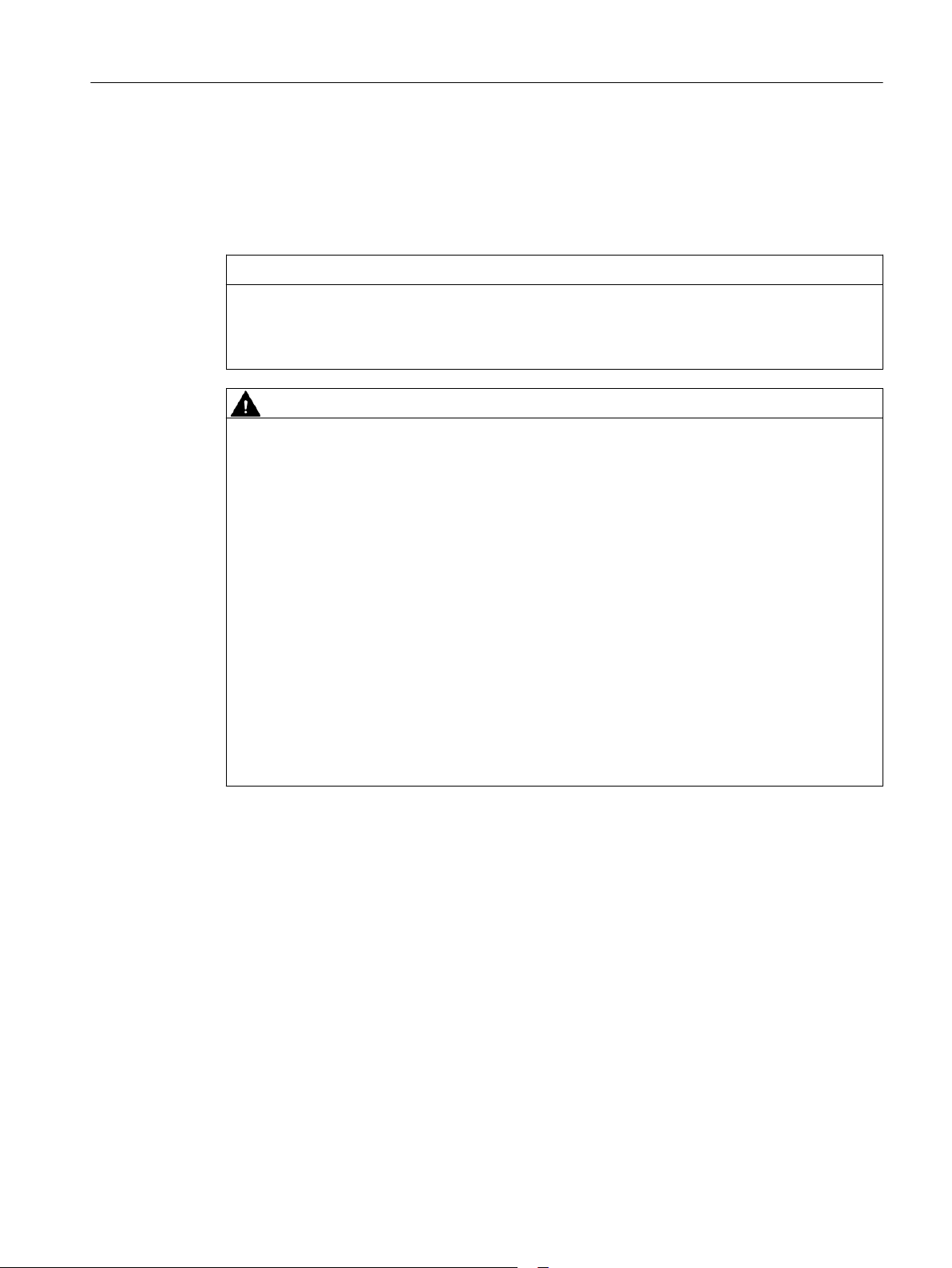
NOTICE
Damage to the device if the wrong battery is used
The device can be damaged if the incorrect lithium battery is used.
Only replace the battery using an original battery.
WARNING
Danger of explosion and the release of harmful substances!
Improper handling of lithium batteries can result in an explosion of the batteries.
Explosion of the batteries and the released pollutants can cause severe physical injury. Worn
batteries jeopardize the function of the device.
Maintenance
8.4 Replace the battery
Carefully comply with the following when handling lithium batteries:
● Replace the lithium battery only with an identical battery or types recommended by the
manufacturer.
● Never throw batteries into fire.
● Do not solder on the body of the battery.
● Never recharge the battery.
● Do not open the battery.
● Do not short-circuit the battery.
● Do not connect the battery with the incorrect polarity.
● Do not heat up the battery above 100 °C.
● Protect the battery from direct sunlight, moisture and condensation.
Data loss when the battery is changed
When a battery is changed, device configuration data are kept in the retentive memory.
The following data are lost:
● Measurement data after the last transfer to SIDRIVE IQ
● The associated date and time of the connectivity module
SIMOTICS CONNECT 400
Operating Instructions, 07/2019 39
Page 42

Maintenance
8.5 Mounting bracket fastening
Note
Save data when the battery has adequate residual capacity
To avoid losing measurement data that has been captured, you can transfer data to
MindSphere while the battery has sufficient residual capacity and before it is replaced.
To do this, use the "MINDSPHERE SYNC" function in the "SIMOTICS CONNECT" menu of the
"SIDRIVE IQ Config" application.
Procedure
1. Visually inspect the new battery for any damage.
2. Release the 2 central fastening screws at the front cover. You can find the relevant mounting
elements for the connectivity module in Chapter Mounting and installation (Page 15).
Do not completely turn the screws from the cover so that the screws are not lost.
3. Remove the front cover.
4. Remove the battery connector by gently withdrawing it from the socket.
5. Remove the batteries from the holder.
6. Insert the new batteries. Carefully observe the battery polarity.
7. Insert the battery connector by gently pressing on the socket provided.
8. Reattach the front cover. Carefully ensure that the cover is precisely in the correct position.
9. Tighten the 2 central fastening screws at the front cover.
10.Reenter the date and time of day:
– Automatically: Within approximately 1 minute of restarting the connectivity module, the
device time is automatically corrected via NTP
– Manually: Using the "SIDRIVE IQ Config" application and the "BLE name", establish a
connection to the connectivity module. The mobile device time is transferred to the
connectivity module.
8.5 Mounting bracket fastening
The connectivity module is mounted on a bracket in the factory. This mounting bracket is
permanently bonded to the motor. The connectivity module screwed to the mounting bracket.
You can mount the connectivity module on the opposite side of the motor if the factory mounted
position is not suitable for space reasons. To do this, use the mounting kit comprising mounting
bracket and adhesive (Page 43).
Carefully ensure that there is adequate clearance between the connectivity module and
current-carrying conductors. The center of the connectivity module should be located at the
height of the center cooling rib of the motor. When the terminal box is located at the drive end,
the center of the connectivity module should be 210 mm away from the non-drive end bearing
SIMOTICS CONNECT 400
40 Operating Instructions, 07/2019
Page 43
Maintenance
8.5 Mounting bracket fastening
shield. If the terminal box is located at the non-drive end, then the distance between the center
of the connectivity module and drive end bearing shield should be 210 mm.
Note
Using the adhesive provided in the mounting kit
Carefully comply with the usage instructions provided on the adhesive package.
The adhesive dries quickly. Work quickly.
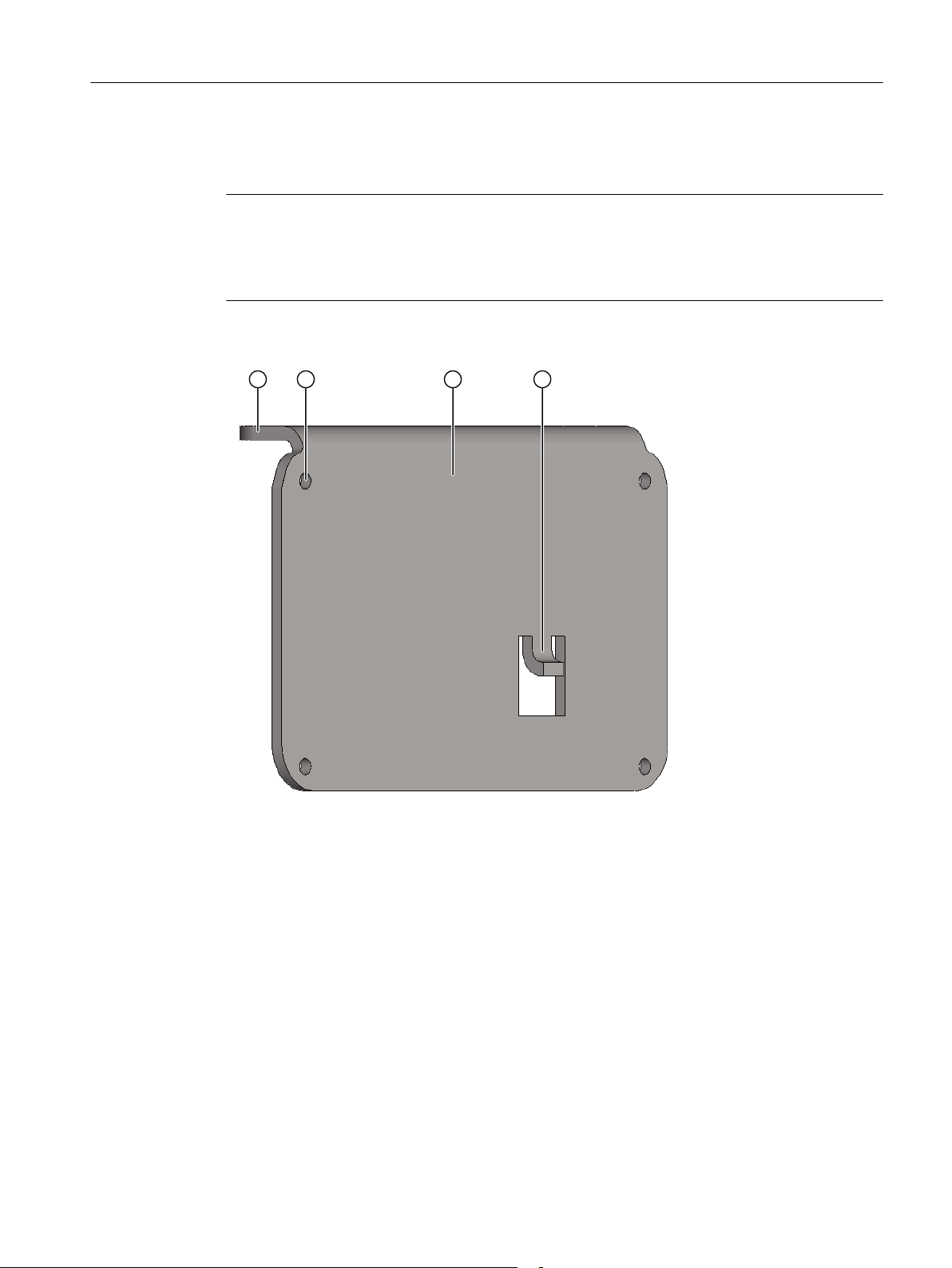
The mounting bracket is shown in the following diagram:
① Short arm of the mounting bracket: Inner side for bonding to the motor cooling ribs through the
full surface area
② Thread for the fastening screws of the connectivity module
③ Long arm of the mounting bracket: Surface for attaching the connectivity module using screws
④ Thermally conducting contact
Requirements
● The mounting bracket is clean, dry and free of any grease.
● The cooling ribs to which the mounting bracket is to be bonded are thoroughly cleaned, dry
and free of any grease.
● You have carefully read the usage instructions on the adhesive package.
SIMOTICS CONNECT 400
Operating Instructions, 07/2019 41
Page 44
Maintenance
8.5 Mounting bracket fastening
Procedure
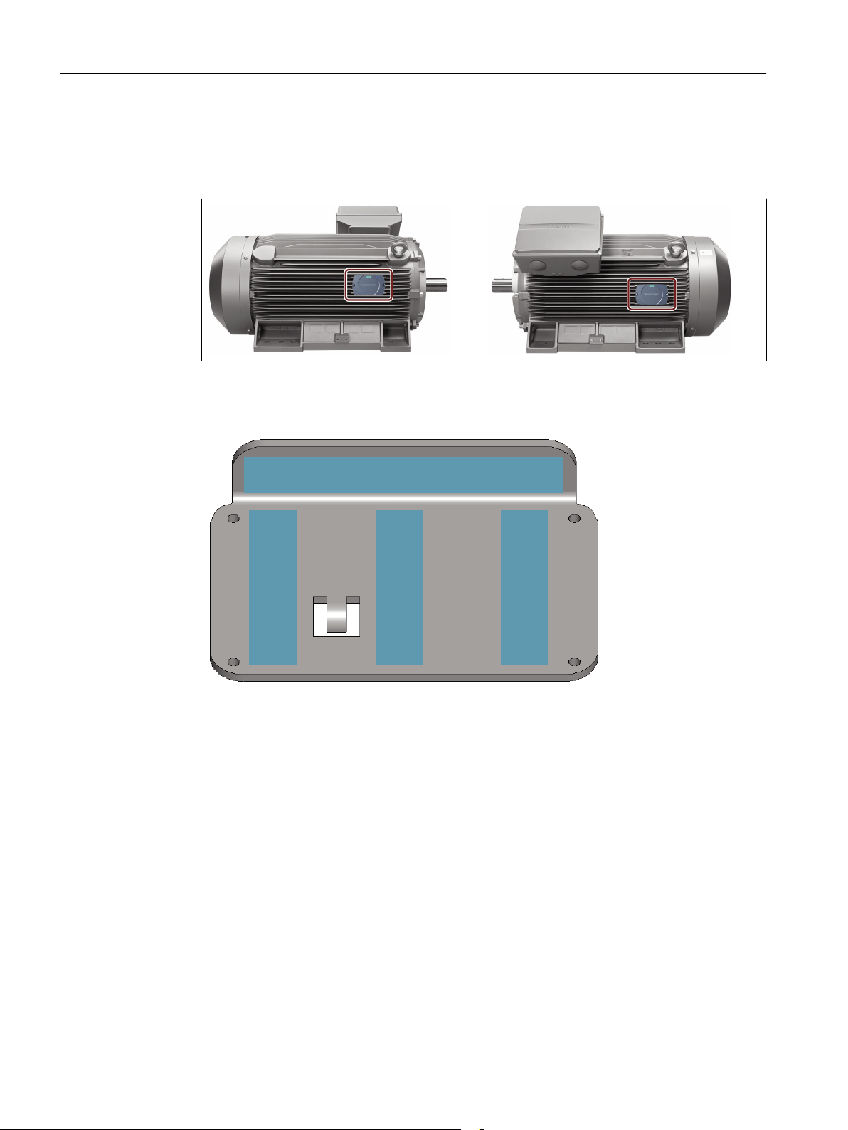
1. Select the new position for the connectivity module on the motor. Two positions for the
connectivity module on the motor are shown as example in the following diagrams.
2. Apply the adhesive to the recommended locations on the inner side of the mounting bracket.
Carefully ensure that no adhesive enters the threads for the fastening screws.
3. Place the mounting bracket on the motor cooling ribs. The short arm of the mounting bracket
must be in complete contact with a cooling rib. The long mounting bracket arm must be in
contact with one or several edges of the cooling ribs.
4. Press the mounting bracket onto the motor cooling ribs using your hand.
5. Allow the adhesive applied to the mounting bracket to dry. Carefully comply with the usage
instructions provided on the adhesive package.
6. Mounting the connectivity module onto the bracket (Page 38).
7. Allow the adhesive to completely dry.
SIMOTICS CONNECT 400
42 Operating Instructions, 07/2019
Page 45

Replacement parts
Spares on Web
A list of available spare parts is available through the spare parts service "Spares on Web
(
https://www.sow.siemens.com/)" by selecting the serial number and the MLFB of the motor.
The link to the Spares on Web for each configured asset is available in the SIDRIVE IQ
application "IQ Fleet".
Spare parts for the connectivity module
You can order spare parts through the regional Siemens support organization. When ordering
spare parts, enter the following data:
● Order number of the connectivity module
● Serial number of the motor on which the connectivity module is mounted
● Order number (MLFB) of the motor on which the connectivity module is mounted
The following spare parts are available for the connectivity module:
● SIMOTICS CONNECT 400 including battery (9LD2100-0BA00-0AA0)
9
● Mounting kit comprising mounting bracket and adhesive (9LD2900-0AA00-0AB0)
● Battery (9LD2900-0AA00-0AA0)
Additional information
A brief description on how to use "Spares on Web" is provided in the Internet (https://
support.industry.siemens.com/cs/ww/en/view/25248520).
SIMOTICS CONNECT 400
Operating Instructions, 07/2019 43
Page 46

Replacement parts
SIMOTICS CONNECT 400
44 Operating Instructions, 07/2019
Page 47

Disposal
Country-specific legislation
The product uses materials that you can recover or recycle. Correctly separating materials
helps to simply recycle important materials.
● When disposing of the product or waste that occurs in the individual lifecycle phases,
carefully comply with country-specific legislation.
● Please contact your local authorities for more information about disposal.
10.1 Disposing of the connectivity module
10
1. Check whether the connectivity module can still function.
2. If the connectivity module can still function reset all of the settings to the factory settings
(Page 37).
3. Remove the battery.
4. Dispose of the battery in compliance with the applicable national regulations or recycle the
battery (Page 45).
5. Dispose of the connectivity module in compliance with the applicable national regulations or
recycle it.
Comply with the directive of the European Parliament and Counsel regarding old electrical
and electronic devices (http://eur-lex.europa.eu/legal-content/EN/TXT/?
uri=CELEX:32012L0019).
10.2 Disposing of the battery
When disposing, observe the following environmental protection measures:
● Do not throw used lithium batteries into household waste (garbage).
● Dispose of used lithium batteries individually as special waste.
● Dispose of used lithium batteries in compliance with all of the local regulations.
● Used lithium batteries can be recycled. Recycle your old batteries!
SIMOTICS CONNECT 400
Operating Instructions, 07/2019 45
Page 48

Disposal
10.2 Disposing of the battery
SIMOTICS CONNECT 400
46 Operating Instructions, 07/2019
Page 49

Service & Support
A.1 Siemens Industry Online Support
Technical questions or additional information
If you have any technical questions or require additional information, please contact Technical
Support (
Have the following connectivity module data ready:
● Type
● Order number
Contact person
Please contact your local partner if you wish to request service. This office will contact the
responsible service center on your behalf. You can find your local partner in the relevant contact
database (www.siemens.com/yourcontact).
https://support.industry.siemens.com/cs/ww/en/sc/4868).
A
SIMOTICS CONNECT 400
Operating Instructions, 07/2019 47
Page 50

Service & Support
A.1 Siemens Industry Online Support
SIMOTICS CONNECT 400
48 Operating Instructions, 07/2019
Page 51

Certificates and Licenses
B.1 Certificates, approvals, standards
Note
Approvals are only valid when marked on the product
The specified approvals apply only when the corresponding mark is printed on the product. You
can check which of the following approvals have been granted for your product by the markings
on the type plate.
CE marking
The SIMOTICS CONNECT 400 product complies with the requirements and protective goals
of the following EU Directives.
RED Directive 2014/53/EU
The product is designed for use in an industrial environment.
B
Safety and security requirements EN 62368-1 2014+A11:2017
EN 62311 2008
EMC standards EN 309 489-1 V2.2.0 Draft 2017
EN 301 489-17 V3.2.0 Draft 2017
Efficient use of a spectrum EN 300 328 V2.2.1
The product meets these requirements if you adhere to the installation guidelines and safety
instructions included in these operating instructions during installation and operation.
Declaration of Conformity
The EU Declaration of Conformity is kept available for the responsible authorities in
accordance with the above-mentioned EU Directive at the following address:
SIEMENS AG
Vogelweiherstr. 1-15
DE-90441 Nuremberg, Germany
Further applied standards
Assessment of electrical and electronic devices regarding restricting hazardous substances:
● RoHS Directive RoHS 2011/65/EU
● EN50581 2012
SIMOTICS CONNECT 400
Operating Instructions, 07/2019 49
Page 52

Certificates and Licenses
B.2 Licenses
B.2 Licenses
Use of open source software (OSS)
The SIMOTICS CONNECT 400 product uses open source software that has either been left
unchanged, or has been modified by us. Licensing terms and sources that are to be published
are included on the CD-ROM that is supplied with the SIMOTICS CONNECT 400.
SIMOTICS CONNECT 400
50 Operating Instructions, 07/2019
Page 53

Index
A
Approvals, 49
Assigning the motor, 25
B
Battery
Disposing, 45
Operating time, 31
Replacing, 39
Battery replacement, 39
Bluetooth, 14
C
CE marking, 49
Certificates and approvals
CE marking, 49
Declaration of Conformity, 49
EMC Directive, 49
Changing the user name, 32
Changing user data, 32
L
Logging in, 20
M
Measurement intervals, 31
MindSphere
Logging in, 26
Mounting and installation, 15
Battery, 15
O
Onboarding, 23
On-site service, 47
Overview, 9
P
Password
Changing, 32
Reset, 37
D
Data security, 11
Declaration of Conformity, 49
Disclaimer of liability, 5
Disposal, 45
E
EMC Directive, 49
Establishing a connection, 17
Exit onboarding, 27
I
Identifying the connectivity module, 31
Identifying the firmware version, 35
Installing SIDRIVE IQ Config, 17
Q
Qualified personnel, 7
R
Replacement part, 38
Replacement parts
Ordering data, 43
Spares on Web, 43
Replacing, 38
Requirements, 13
Restoring factory settings, 37
S
Safety instructions, 7
Setting up a WLAN connection, 22
SIDRIVE IQ Fleet, 9
Spares on Web, 43
Start onboarding, 24
SIMOTICS CONNECT 400
Operating Instructions, 07/2019 51
Page 54

Index
Storage conditions, 13
Synchronization intervals, 31
T
Technical Support, 47
Transport conditions, 13
U
Updating SIDRIVE IQ Config, 35
Updating the firmware, 35
V
Visual inspection, 13
SIMOTICS CONNECT 400
52 Operating Instructions, 07/2019
Page 55

Page 56

Further Information
https://www.siemens.com/sidrive-iq
Siemens AG
Digital Industries
Postfach 48 48
90026 Nürnberg
GERMANY
 Loading...