

Page 1
Page 2

Page 3
SIMOTICS A-1FV5/1PV5
synchronous/induction motors
___________________
___________________
___________________
___________________
___________________
___________________
___________________
___________________
___________________
___________________
___________________
SIMOTICS A-1FV5/1PV5 synchronous/induction motors
Operating Instructions
03/2014
610.45002.40
Introduction
1
Safety notes
2
Description
3
Preparing for use
4
Mounting
5
Connection
6
Commissioning
7
Operation
8
Service and maintenance
9
Decommissioning and
disposal
10
Appendix
A
Page 4

Siemens AG
Industry Sector
Postfach 48 48
90026 NÜRNBERG
GERMANY
Order number: 610.45002.40
Ⓟ
Copyright © Siemens AG 2014.
All rights reserved
Legal information
Warning notice system
DANGER
indicates that death or severe personal injury will result if proper precautions are not taken.
WARNING
indicates that death or severe personal injury may result if proper precautions are not taken.
CAUTION
indicates that minor personal injury can result if proper precautions are not taken.
NOTICE
indicates that property damage can result if proper precautions are not taken.
Qualified Personnel
personnel qualified
Proper use of Siemens products
WARNING
Siemens products may only be used for the applications described in the catalog and in the relevant technical
maintenance are required to ensure that the products operate safely and without any problems. The permissible
ambient conditions must be complied with. The information in the relevant documentation must be observed.
Trademarks
Disclaimer of Liability
This manual contains notices you have to observe in order to ensure your personal safety, as well as to prevent
damage to property. The notices referring to your personal safety are highlighted in the manual by a safety alert
symbol, notices referring only to property damage have no safety alert symbol. These notices shown below are
graded according to the degree of danger.
If more than one degree of danger is present, the warning notice representing the highest degree of danger will
be used. A notice warning of injury to persons with a safety alert symbol may also include a warning relating to
property damage.
The product/system described in this documentation may be operated only by
task in accordance with the relevant documentation, in particular its warning notices and safety instructions.
Qualified personnel are those who, based on their training and experience, are capable of identifying risks and
avoiding potential hazards when working with these products/systems.
for the specific
Note the following:
documentation. If products and components from other manufacturers are used, these must be recommended
or approved by Siemens. Proper transport, storage, installation, assembly, commissioning, operation and
All names identified by ® are registered trademarks of Siemens AG. The remaining trademarks in this publication
may be trademarks whose use by third parties for their own purposes could violate the rights of the owner.
We have reviewed the contents of this publication to ensure consistency with the hardware and software
described. Since variance cannot be precluded entirely, we cannot guarantee full consistency. However, the
information in this publication is reviewed regularly and any necessary corrections are included in subsequent
editions.
03/2014 Subject to change
Page 5

Table of contents
1 Introduction ............................................................................................................................................. 7
2 Safety notes ............................................................................................................................................ 9
3 Description ............................................................................................................................................ 15
4 Preparing for use .................................................................................................................................. 23
5 Mounting ............................................................................................................................................... 29
2.1 General safety information ............................................................................................................. 9
2.2 Safety and operating instructions................................................................................................. 10
2.3 Observing the five safety rules ..................................................................................................... 11
2.4 Thermal hazard ............................................................................................................................ 11
2.5 Information about electromagnetic fields ..................................................................................... 12
2.6 Electrostatic sensitive devices (ESD) .......................................................................................... 13
3.1 Application .................................................................................................................................... 15
3.2 Rating plate (type plate) ............................................................................................................... 16
3.3 Technical features ........................................................................................................................ 17
3.4 Design .......................................................................................................................................... 18
3.4.1 Regulations .................................................................................................................................. 18
3.4.2 Types of construction ................................................................................................................... 18
3.4.3 Degree of protection .................................................................................................................... 18
3.4.4 Ambient conditions ....................................................................................................................... 19
3.4.5 Cooling ......................................................................................................................................... 19
3.4.6 Noise emission ............................................................................................................................. 22
4.1 Shipment and packaging ............................................................................................................. 23
4.2 Transport and storage .................................................................................................................. 23
4.2.1 Transport ...................................................................................................................................... 23
4.2.2 Storage ......................................................................................................................................... 26
5.1 Installation .................................................................................................................................... 29
5.2 Fixing ............................................................................................................................................ 30
5.3 Attaching the output elements ..................................................................................................... 31
5.4 Vibration load ............................................................................................................................... 33
SIMOTICS A-1FV5/1PV5 synchronous/induction motors
Operating Instructions, 03/2014, 610.45002.40
5
Page 6

Table of contents
6 Connection ........................................................................................................................................... 35
7 Commissioning ..................................................................................................................................... 43
8 Operation .............................................................................................................................................. 49
9 Service and maintenance ...................................................................................................................... 53
10 Decommissioning and disposal ............................................................................................................. 57
A Appendix .............................................................................................................................................. 61
Index .................................................................................................................................................... 65
6.1 Mechanical connection of water cooling system ......................................................................... 35
6.2 Electrical connection ................................................................................................................... 36
6.2.1 Safety information ....................................................................................................................... 36
6.2.2 Cable entry and routing ............................................................................................................... 37
6.2.3 Circuit diagram ............................................................................................................................ 38
6.2.4 Terminal box ............................................................................................................................... 39
6.2.5 Data for electrical connection ...................................................................................................... 40
6.2.6 Signal connection ........................................................................................................................ 41
6.2.7 Connecting the temperature sensor ............................................................................................ 42
6.2.8 Connecting the ground conductor ............................................................................................... 42
6.2.9 Connecting-up a converter .......................................................................................................... 42
7.1 Measures prior to commissioning ............................................................................................... 43
7.2 Performing a trial run ................................................................................................................... 45
7.3 Checking the insulation resistance ............................................................................................. 45
7.4 Switching on the motor ................................................................................................................ 47
7.5 Liquid cooling .............................................................................................................................. 47
8.1 Safety instructions during operation ............................................................................................ 49
8.2 Stoppages ................................................................................................................................... 50
8.3 Shutdown .................................................................................................................................... 50
8.4 Faults ........................................................................................................................................... 50
9.1 Safety information ....................................................................................................................... 53
9.2 Maintenance intervals ................................................................................................................. 55
9.3 General inspection guidelines ..................................................................................................... 56
9.4 Bearing replacement intervals .................................................................................................... 56
10.1 Decommissioning ........................................................................................................................ 57
10.2 Disposal....................................................................................................................................... 57
A.1 List of abbreviations .................................................................................................................... 61
A.2 Siemens Service Center ............................................................................................................. 62
A.3 Declaration of conformity ............................................................................................................ 63
SIMOTICS A-1FV5/1PV5 synchronous/induction motors
6 Operating Instructions, 03/2014, 610.45002.40
Page 7

1
Note
All data that are generally applicable for the motor also always apply to the generator.
Text format features
Note
A Note is an important item of information about the product, handling of the product
or the relevant section of the document. Notes provide you with help or further
suggestions/ideas.
These operating instructions describe the motor and explain how to handle the motor from
the delivery to the disposal stage.
Before you start using the motor, you must read these operating instructions to ensure safe,
problem-free operation and to maximize the service life.
Siemens strives continually to improve the quality of information provided in these operating
instructions. If you find any mistakes or would like to offer suggestions about how this
document could be improved, please contact the Siemens Service Center.
Always follow the safety instructions and notices in these operating instructions. The warning
notice system is explained on the rear of the inside front.
In addition to the safety-related notices and instructions which you must read, you will find
the text in these operating instructions is formatted in the following way:
1. Handling instructions are always formatted as a numbered list. Always perform the steps
● Lists are formatted as bulletted lists.
in the order given.
– Lists on the second level are hyphenated.
SIMOTICS A-1FV5/1PV5 synchronous/induction motors
Operating Instructions, 03/2014, 610.45002.40
7
Page 8

Introduction
SIMOTICS A-1FV5/1PV5 synchronous/induction motors
8 Operating Instructions, 03/2014, 610.45002.40
Page 9
2
2.1
General safety information
Safety and commissioning information for converter-fed low-voltage three-phase motors
DANGER
qualified, responsible personnel
injury or material damage
national, local and plant/system-specific regulations and requirements
Special versions
construction variants
type
designation and serial number
(in accordance with the Low Voltage Directive 2006/95/EC)
All work associated with transporting, connecting, commissioning, and maintaining the
motors must be carried out by
note IEC 60364).
(DIN EN 50110-1;
Failure to follow proper procedures may result in
The valid
carefully observed.
aspects. If in doubt, you are strongly advised to contact the manufacturer specifying the
carried out by the SIEMENS Service Center.
Vehicles with converter-fed low-voltage three-phase motors must fulfill the protective
requirements of the EMC Directive 2004/108/EC.
The user is responsible for ensuring that installation is carried out properly. The signal and
power cables must be shielded.
The information provided by the converter manufacturer regarding EMC-compliant
installation must be observed.
and
may differ with respect to certain technical
(see rating plate) or arrange for any maintenance work to be
.
must be
SIMOTICS A-1FV5/1PV5 synchronous/induction motors
Operating Instructions, 03/2014, 610.45002.40
9
Page 10
Safety notes
2.2
Safety and operating instructions
The safe use of electrical machines
WARNING
Rotating or live parts
Qualified personnel
Note
Siemens Service Center
We recommend engaging the support and services of your local Siemens Service Center
for all planning, installation, commissioning, and maintenance work.
2.2 Safety and operating instructions
Rotating or live parts are dangerous.
Fatal or severe injuries and substantial material damage can occur if the required covers
are removed or if the machines are not handled, operated, or maintained properly.
Covers must only be removed and the motor operated in accordance with the relevant
regulations. The motor must be maintained on a regular basis.
These operating instructions only contain the information necessary for ensuring that the
motor is operated by properly trained personnel in accordance with its intended purpose.
Those responsible for plant safety must ensure the following:
● The basic planning work for the system and all work relating to transportation, assembly,
installation, commissioning, maintenance and repairs is carried out by qualified personnel
and checked by responsible, suitably skilled personnel.
● The operating instructions and the motor documentation are available at all times.
● The technical data and specifications relating to installation, connection, ambient and
operating conditions are taken into account at all times.
● The system-specific installation and safety regulations are observed.
● Personal protective equipment is used.
● Unqualified persons must not work on or in the vicinity of these motors at any time.
SIMOTICS A-1FV5/1PV5 synchronous/induction motors
10 Operating Instructions, 03/2014, 610.45002.40
Page 11
Safety notes
2.3
Observing the five safety rules
Five safety rules
2.4
Thermal hazard
CAUTION
Do not touch any hot surfaces!
Only operate the motors in conjunction with effective temperature control.
2.3 Observing the five safety rules
For your personal safety and to prevent material damage when working on the machine,
always observe the safety instructions and the following five safety rules. Apply the five
safety rules in the order stated before starting work at the machine.
1. Disconnect the system.
You must also make sure that the auxiliary circuits are also disconnected.
2. Protect against reconnection.
3. Make sure that the equipment is de-energized.
4. Ground and short-circuit.
5. Cover or enclose adjacent components that are still live.
When work has been completed, remove these measures in reverse order.
The surface temperature of the motors can exceed 65 °C.
Temperature-sensitive components (electric cables, electronic components) must not be
placed on hot surfaces. If the motors overheat, this can destroy the windings/bearings and
the permanent magnet may become demagnetized
SIMOTICS A-1FV5/1PV5 synchronous/induction motors
Operating Instructions, 03/2014, 610.45002.40
11
Page 12
Safety notes
2.5
Information about electromagnetic fields
Note
Permanent magnets
The rotors of 1FV5 synchronous motors contain permanent magnets with high magnetic flux
densities and strong forces of attraction to ferromagnetic bodies.
Persons with cardiac pacemakers are endangered in the vicinity of a disassembled rotor.
Data stored o
WARNING
Electromagnetic fields
2.5 Information about electromagnetic fields
n electronic data carriers can be destroyed.
Electromagnetic fields are generated when electrical power engineering installations
(e.g. transformers, converters, or motors) are operated.
Electromagnetic fields can interfere with electronic devices, which could cause them to
malfunction. Heart pacemakers can be affected, for example, which could potentially
damage a person's health or even result in death. Steps must be taken, therefore, to
ensure that persons with heart pacemakers cannot enter these areas.
The plant operator is responsible for taking appropriate measures (labels and hazard
warnings) to adequately protect operating personnel and others against any possible risk.
● Observe the relevant nationally applicable health and safety regulations. In Germany,
"electromagnetic fields" are subject to regulations BGV B11 and BGR B11 stipulated by
the German statutory industrial accident insurance institution.
● Display adequate hazard warning notices.
● Place barriers around hazardous areas.
● Take appropriate measures (e.g. shields) to reduce electromagnetic fields at their source.
SIMOTICS A-1FV5/1PV5 synchronous/induction motors
12 Operating Instructions, 03/2014, 610.45002.40
Page 13

Safety notes
2.6
Electrostatic sensitive devices (ESD)
ESD guidelines
NOTICE
Electrostatic discharge
NOTICE
Use conductive packaging material
2.6 Electrostatic sensitive devices (ESD)
Electronic modules contain components that can be destroyed by electrostatic discharge.
These modules can be easily destroyed by improper handling.
To protect your equipment against damage, follow the instructions given below.
● Never touch electronic modules unless absolutely necessary in the course of
maintenance and repair procedures.
● If the modules have to be touched, the body of the person concerned must be
electrostatically discharged immediately beforehand and be grounded.
● Electronic modules should not come into contact with electrically insulating materials
(e.g. plastic foil, plastic parts, insulating table supports, or clothing made of synthetic
fibers).
● Always place the modules on conductive bases.
● Always store and transport electronic modules or components in conductive packaging
(e.g. metallized plastic or metal containers).
Electronic modules must be stored, transported, and dispatched in conductive
packaging.
Electronic modules that are not correctly stored, transported, or dispatched can be
damaged.
Pack electronic modules in appropriate conductive packaging (e.g. foam rubber or
aluminum foil).
SIMOTICS A-1FV5/1PV5 synchronous/induction motors
Operating Instructions, 03/2014, 610.45002.40
13
Page 14

Safety notes
(1)
Sitting
(2)
Standing
(3)
Standing/sitting
ESD protective measures
a
= conductive floor
b
= ESD table
c
= ESD footwear
d
= ESD coat
s
= ESD wrist strap
f
= cubicle ground connection
2.6 Electrostatic sensitive devices (ESD)
The necessary ESD protective measures for electrostatically sensitive devices are illustrated
once again in the following drawings:
Figure 2-1 ESD protective measures
SIMOTICS A-1FV5/1PV5 synchronous/induction motors
14 Operating Instructions, 03/2014, 610.45002.40
Page 15

3
3.1
Application
Proper usage
Mode of operation and design
The motors are designed for installation in electrically driven vehicles. and are characterized
by their high power density, ruggedness, long lifetime, and overall reliability. The three-phase
motors are either closed-loop speed or torque controlled using a converter. The direct
connection to the three-phase line supply is not permissible. It is forbidden to install them in
hazardous areas unless they are explicitly designed for this.
The 1PV5 motors are liquid-cooled squirrel-cage induction motors.
The 1FV5 generators are liquid-cooled synchronous motors with permanent magnet rotors.
Both active parts are equipped with two temperature sensors integrated in the stator winding,
where the second can be used as a reserve.
An encoder system for sensing the speed and direction of rotation is optionally installed in
the NDE bearing shield of the motors.
SIMOTICS A-1FV5/1PV5 synchronous/induction motors
Operating Instructions, 03/2014, 610.45002.40
15
Page 16
Description
3.2
Rating plate (type plate)
No.
Description
No.
Description
L010
MLFB
L170
Rated power PN (3)
L020
Factory serial number
L180
Unit rated power (3)
L025
Consecutive number
L190
Rated current IN (3)
L040
Options
L210
Rated speed nN (3)
L060
Maximum speed n
L230
Temperature class
L070
Operating mode (1)
L240
Degree of protection
L071
Rated time (1)
L250
Type of construction
L072
Unit rated time (1)
L260
Revision number
L080
Rated power PN (1)
L270
Weight
L090
Rated current IN (1)
L280
Temperature sensor
3.2 Rating plate (type plate)
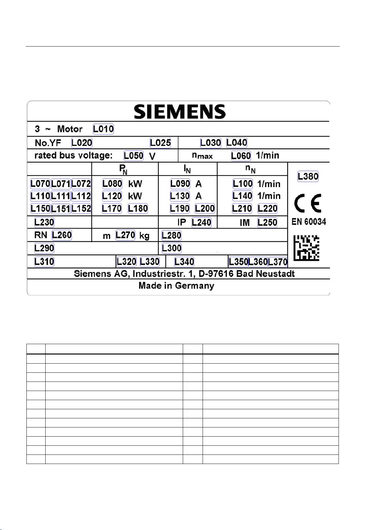
The rating plate (type plate) shows the technical specifications for the supplied motor.
Figure 3-1 Schematic layout of rating plate
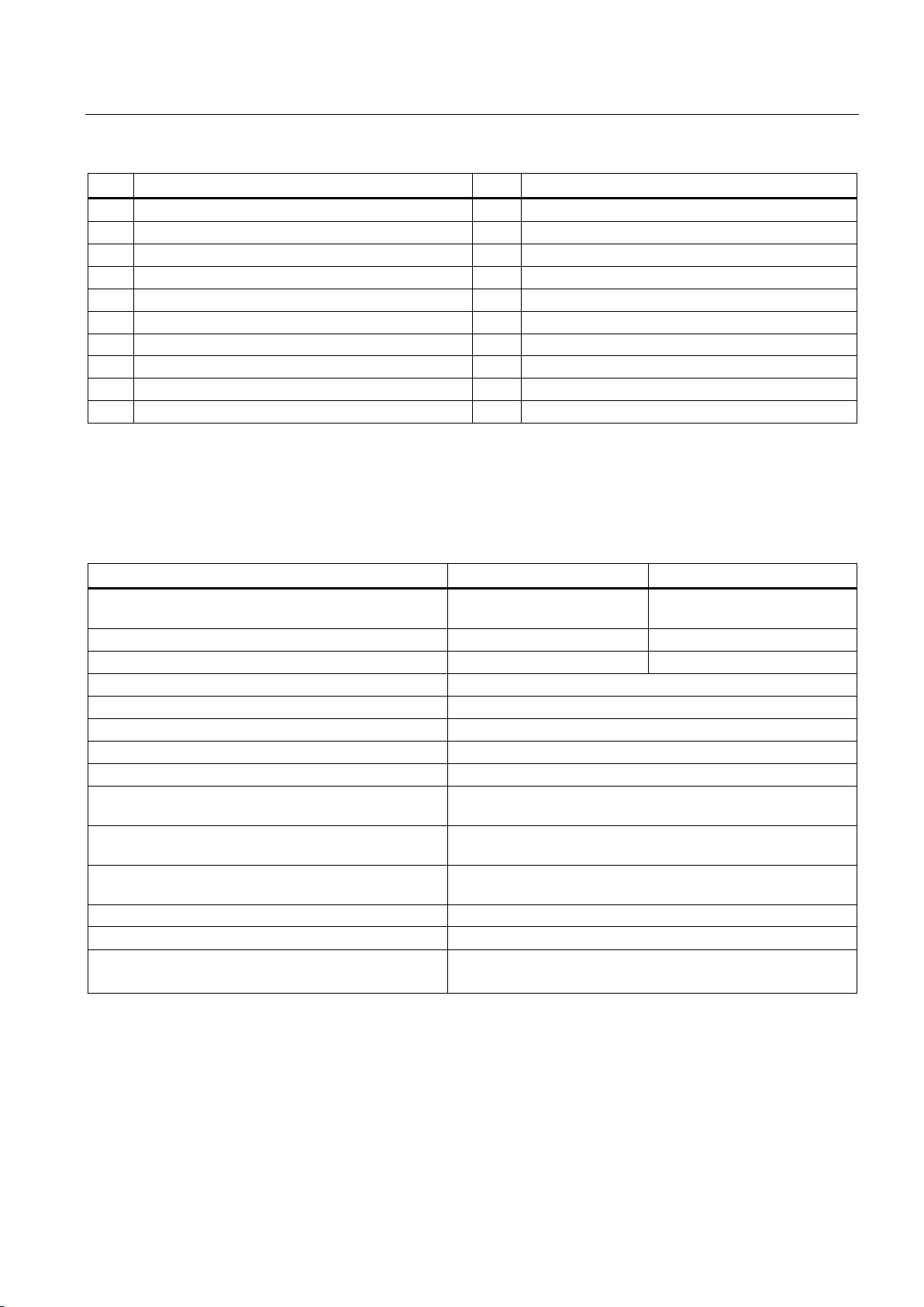
Table 3- 1 Elements on the rating plate
L030 Z: (For options) L200 Unit rated current IN (3)
L050 Rated voltage L220 Rated speed nN (3)
max
SIMOTICS A-1FV5/1PV5 synchronous/induction motors
16 Operating Instructions, 03/2014, 610.45002.40
Page 17
Description
No.
Description
No.
Description
L100
Rated speed nN (1)
L290
Encoder (encoder)
L110
Operating mode (2)
L300
Optional customer information
L111
Rated time (2)
L310
Cooling method
L112
Unit rated time (2)
L320
Coolant flow
L120
Rated power PN (2)
L330
Unit coolant flow
L130
Rated current IN (2)
L340
Cooling pressure
L140
Rated speed nN(2)
L350
Maximum value
L150
Operating mode (3)
L360
Maximum coolant temperature
L151
Rated time (3)
L370
Unit maximum coolant temperature
L152
Unit rated time (3)
L380
UL mark
3.3
Technical features
1FV5
1PV5
synchronous motor
Magnet material
Rare-earth magnetic material
---
Speed encoder (optional)
Rotor position encoder (RPE)
Toothed-wheel encoder (64 pin)
Insulation of stator winding according to EN 60034–1
Thermal class 180 (H)
Cooling
Liquid cooling
Installation altitude according to EN 60034-1
≤ 2500 m above sea level, otherwise power derating
Degree of protection to EN60034-5
IP65/IP69K (without DE shaft output)
EN 60034-11
(half-key balancing)
in accordance with DIN 42955
Vibration severity grade according to EN 60034-14
Grade A is maintained up to rated speed
Sound pressure level according to DIN EN ISO 1680
75 dB (A) + 3 dB (A) tolerance
12-pin signal connector
3.3 Technical features
Table 3- 2 Technical features
Type of motor Permanent-magnet
Type of construction acc. to EN 60034–7 IM B5
Temperature monitoring in accordance with
DE shaft extension accordance with DIN 748-3 Plain or geared shaft, optional shaft with fitted key and keyway
Radial eccentricity, concentricity and axial eccentricity
Connection Terminal board in the terminal box for power
2 x KTY 84-130 temperature sensor in the stator winding
Tolerance N (normal)
Induction motor
SIMOTICS A-1FV5/1PV5 synchronous/induction motors
Operating Instructions, 03/2014, 610.45002.40
17
Page 18
Description
3.4
Design
3.4.1
Regulations
Feature
Standard
Rated and operation characteristics
IEC/EN 60034-1
Degree of protection
IEC/EN 60034-5
Cooling
IEC/EN 60034-6
Type of construction
IEC/EN 60034-7
Terminal markings
IEC/EN 60034-8
Noise emission
IEC/EN 60034-9
Temperature monitoring
IEC/EN 60034-11
Vibration severity grades
IEC/EN 60034-14
(1)
The degree of protection and type of construction of the motor are stamped on its rating plate.
Note
Make sure that your end product is in compliance with all of the applicable legislation!
You
and requirements.
3.4.2
Types of construction
3.4.3
Degree of protection
3.4 Design
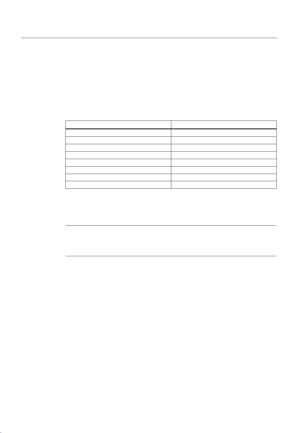
The motors comply with the following regulations according to IEC 60034-x/EN 60034-x:
Table 3- 3 Regulations that have been applied
(1)
(1)
The three-phase motors comply with the relevant sections of EN 60034 and EN 60204-1.
Three-phase motors comply with Low-Voltage Directive 2006/95/EC. Standard motors
comply with the UL regulations. "UR" is stamped on the rating plate of these motors.
must take into account the applicable national, local, and system-specific regulations
The motor has type construction IM B5.
The motors have degree of protection IP65/IP69K. In order to guarantee the degree of
protection, the drive end flange must be suitably implemented.
SIMOTICS A-1FV5/1PV5 synchronous/induction motors
18 Operating Instructions, 03/2014, 610.45002.40
Page 19

Description
3.4.4
Ambient conditions
3.4.5
Cooling
Water cooling
Coolant
Water/anti-freeze mixture, 50/50 %
Female thread in the bearing shield Pg 13.5 /8 deep
Lower values will result in a derating
Max. pressure at inlet
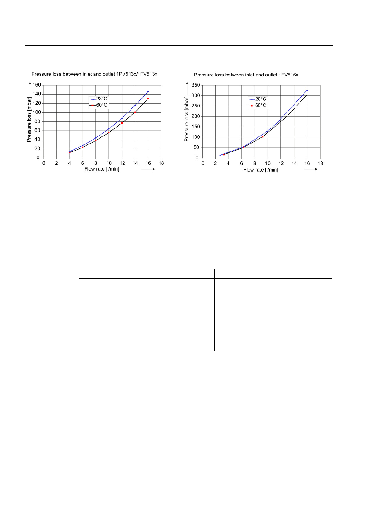
max. 2.5 bar
< 0.4 bar for minimum cooling water flow with 1FV516
at T
<60 °C; T
> -40 °C
temperature, without derating
higher values will result in derating
3.4 Design
The motors are designed for ambient temperatures from -40 °C to +70 °C and installation
altitudes up to 2500 m above sea level. In the case of different ambient conditions, contact
the manufacturer.
The motor can only be operated in a closed coolant circuit with a cooling unit. The motor is
connected to the cooling circuit using two hose connections with an outer diameter of 18 mm
at the NDE bearing shield of the motor. On motors with angled hose connections, after
loosening the locknuts they can be adjusted in both directions (preferred direction clockwise;
max. 1 revolution). After adjusting the position, the coolant connections must be fixed by
tightening the union nuts.
The inlet and outlet connections can be selected as required.
Table 3- 4 Technical data of the water cooling
Cooling water connection Hose connection with an outer diameter of 18
Cooling water flow 16 l/min
Pressure loss between inlet and
outlet
Min. cooling water inlet temperature T
Maximum cooling water inlet
< 0.2 bar for minimum cooling water flow with
1PV513/1FV513
> T
cool
ambient
≤ 55 °C,
ambient
– 5 K
coolmin
As coolant, only a water/anti-freeze mixture in a ratio of 50 % / 50 % is permissible. Glycol is
recommended as antifreeze. When you select a different anti-freeze, a minimum steadystate temperature of -40 °C must be observed. Different anti-freeze agents should not be
mixed.
A filter (100 µm) must be installed in the inlet pipe to protect the motor against pollution.
Additional protection for the motor must be provided by means of a pressure relief valve
installed downstream from the filter.
If a throttle is needed to restrict the flow, it is best to install it downstream of the motor. It is
not permissible to install the throttle directly in front of the inlet because the effects of
cavitation may damage the motor.
SIMOTICS A-1FV5/1PV5 synchronous/induction motors
Operating Instructions, 03/2014, 610.45002.40
19
Page 20
Description
Contents and chemical composition
Value
pH value
6 … 8
Sulfate ions
< 50 ppm
Dissolved solids
< 340 ppm
Total hardness
< 170 ppm
Electrical conductivity
< 500 μS/cm
Size of any particles in the coolant
< 100 µm
Note
Storing or transporting the motor
The cooling circuit must be emptied when storing the motor, for longer periods when the
motor is out of service and when the motor is being transported.
3.4 Design
Figure 3-2 Pressure losses as a result of volumetric flow
Coolant temperatures below the ambient temperature lead to increased condensation of
water. The difference between the coolant inlet temperature and ambient temperature should
therefore not exceed maximum 5 Kelvin. If the motor is out of operation for a prolonged
period of time, coolant inflow must additionally be interrupted.
The values specified for the cooling water (refer to the following table) correspond to the
requirements of closed cooling circuits. Not all of the specified concentrations will occur in
the cooling water at the same time.
Table 3- 5 Water specifications for the coolant
Chloride ions < 40 ppm
Nitrate ions < 50 ppm
SIMOTICS A-1FV5/1PV5 synchronous/induction motors
20 Operating Instructions, 03/2014, 610.45002.40
Page 21
Description
Materials used in the cooling circuit
Materials and components in the cooling circuit
Material
Used as
Description
Zinc breaks down the glycol-based inhibitors.
fittings
units).
window recommended.
separator for stainless heat sink.
Chapter "Coolant definition".
well as Antifrogen N.
materials (mixed installation)
fittings
fittings and hoses
DEMITTEL; from PE/EPD, supplied from Telle).
fittings
Pipe - hose
the Telle company.
3.4 Design
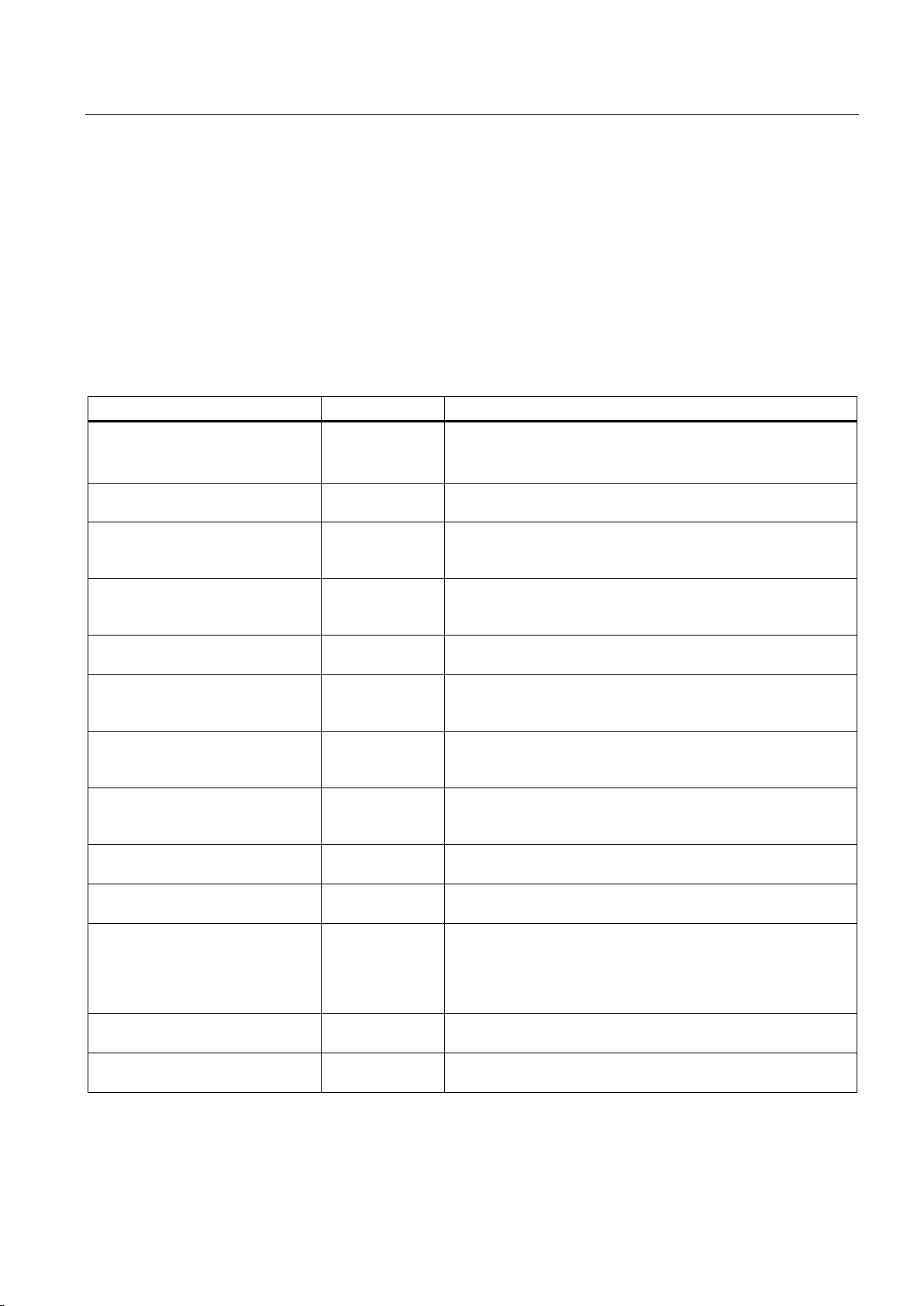
The materials used in the cooling circuit must the coordinated with the materials in the motor
(aluminum alloy) and hose connection (nickel plated brass).
The following table lists a wide variety of materials and components which may or may not
be used in a cooling circuit.
Table 3- 6 Materials and components of a cooling circuit
Zinc Pipes, valves and
fittings
Brass Pipes, valves and
Copper Pipes, valves and
fittings
Common steel (e.g. St37) Pipes Permissible in closed circuits and semi-open circuits with
Cast steel, cast iron Pipes, motors Closed circuit and use of strainers and flushback filters. Fe
High-alloy steel, Group 1 (V2A) Pipes, valves and
fittings
High-alloy steel, Group 2 (V4A) Pipes, valves and
fittings
ABS (AcrylnitrileButadieneStyrene) Pipes, valves and
fittings
Installation comprising different
Pipes, valves and
Use is not permitted. Non-ferrous metals chips can lead to pitting
corrosion in galvanized pipes.
Can be used in closed circuits.
Can be used only in closed circuits in which the heat sink and
copper component are separated (e.g. connection hose of the
inhibitors or Antifrogen N, check for oxide formation, inspection
Can be used for drinking or municipal water with a chloride
content up to <250 ppm, suitable according to definition in
Can be used for drinking or municipal water with a chloride
content up to <500 ppm, suitable according to definition in
Chapter "Coolant definition".
Suitable according to the definition in Chapter "Coolant
definition". Suitable for mixing with inhibitor and/or biocide as
Use is not permitted.
PVC Pipes, valves,
Hoses Reduce the use of hoses to a minimum (device connection).
Gaskets Pipes, valves and
Hose connections Transition
SIMOTICS A-1FV5/1PV5 synchronous/induction motors
Operating Instructions, 03/2014, 610.45002.40
Use is not permitted.
Must not be used as the main pipe for the whole system.
Recommendation: EPDM hoses with an electrical resistance
9
> 10
Ω (e.g. Semperflex FKD supplied from Semperit or
Use of Viton, AFM34, EPDM is recommended.
Secure with clips conforming to EN14420, available, e.g. from
21
Page 22

Description
3.4.6
Noise emission
3.4 Design
The following recommendation applies in order to achieve an optimum motor heatsink
(enclosure) lifetime:
● Engineer a closed cooling circuit with cooling unit manufactured out of stainless steel that
dissipates the heat through a water-water heat exchanger.
● All other components such as cooling circuit cables and fittings manufactured out of ABS,
stainless steel or general construction steel.
In operation, in the speed range extending from 0 up to rated speed, 1PV5 and 1FV5 motors
can reach the following measuring surface sound pressure level Lp(A) according to
ISO 1680:
● 75 dB(A) + 3 dB tolerance
SIMOTICS A-1FV5/1PV5 synchronous/induction motors
22 Operating Instructions, 03/2014, 610.45002.40
Page 23

4
4.1
Shipment and packaging
Checking the delivery for completeness
4.2
Transport and storage
4.2.1
Transport
WARNING
Hazards during lifting and transportation!
The drive systems are assembled on an individual basis. Upon receipt of the delivery, check
immediately whether the items delivered are in accordance with the accompanying
documents. Siemens will not accept any claims relating to items missing from the delivery
and which are submitted at a later date.
● Report any apparent transport damage to the delivery agent immediately.
● Report any apparent defects/missing components to the appropriate Siemens office
immediately.
These safety instructions are part of the scope of supply; keep them in a location where they
can be easily accessed.
The additional rating plate supplied separately with the consignment should be used for
indication of the motor data in the vicinity of the motor.
The rating plate is located in the terminal box.
Use suitable load bearing equipment when transporting and installing the motor. Make sure
that all of the available eyebolts are used during transportation. Country-specific regulations
must be observed.
If the motor is not to be commissioned immediately following delivery, it must be stored in a
dry, dust-free room that is not susceptible to vibration (see "Storage").
Devices and tools that are badly designed, unsuitable, or damaged can result in personal
injury and/or material damage.
Lifting devices, industrial trucks, and load bearing equipment must comply with requirements. Pay attention to the lifting capacity of the hoisting gear. Do not attach any additional
loads. To hoist the motor, use suitable cable-guidance or spreading equipment (particularly
if the motor is equipped with built-on assemblies). The weight of the motor is specified on
the rating plate.
SIMOTICS A-1FV5/1PV5 synchronous/induction motors
Operating Instructions, 03/2014, 610.45002.40
23
Page 24
Preparing for use
WARNING
Transporting and lifting the motor by means of the lifting eyebolts
NOTICE
Transporting and lifting the motor using a cross beam
4.2 Transport and storage
Only lift the motor using the lifting eyebolts on the bearing end shields.
Lifting eyebolts must not be attached to the shaft extension.
Never lift the motor by the Sensor Module or the cooling water pipe system. The motor can
fall down. This can result in death or serious injury as well as damage or total loss of the
motor.
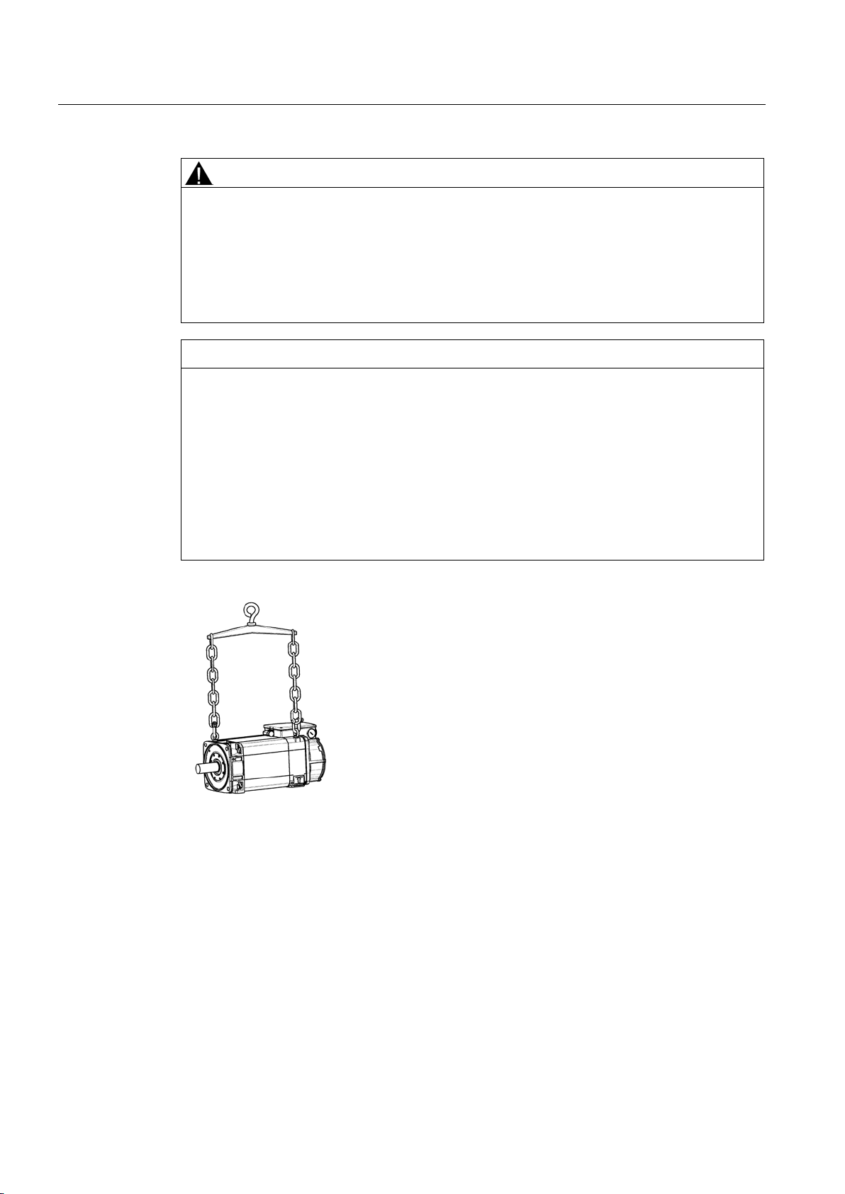
When lifting and transporting the motors using the eyebolts supplied (acc. to DIN 580),
you must use a cross beam!
The following should be noted:
• The ring bolt must be screwed in completely and secured by hand (approx. 8 Nm).
Do not overtighten.
• Do not remove the plain pressboard washer and do not use warped or damaged ring
bolts.
• Loads that run transverse to the ring plane are not permitted.
Figure 4-1 Lifting and transporting the motor with a cross beam (example)
SIMOTICS A-1FV5/1PV5 synchronous/induction motors
24 Operating Instructions, 03/2014, 610.45002.40
Page 25
Preparing for use
Transporting a motor that has already been in operation
4.2 Transport and storage
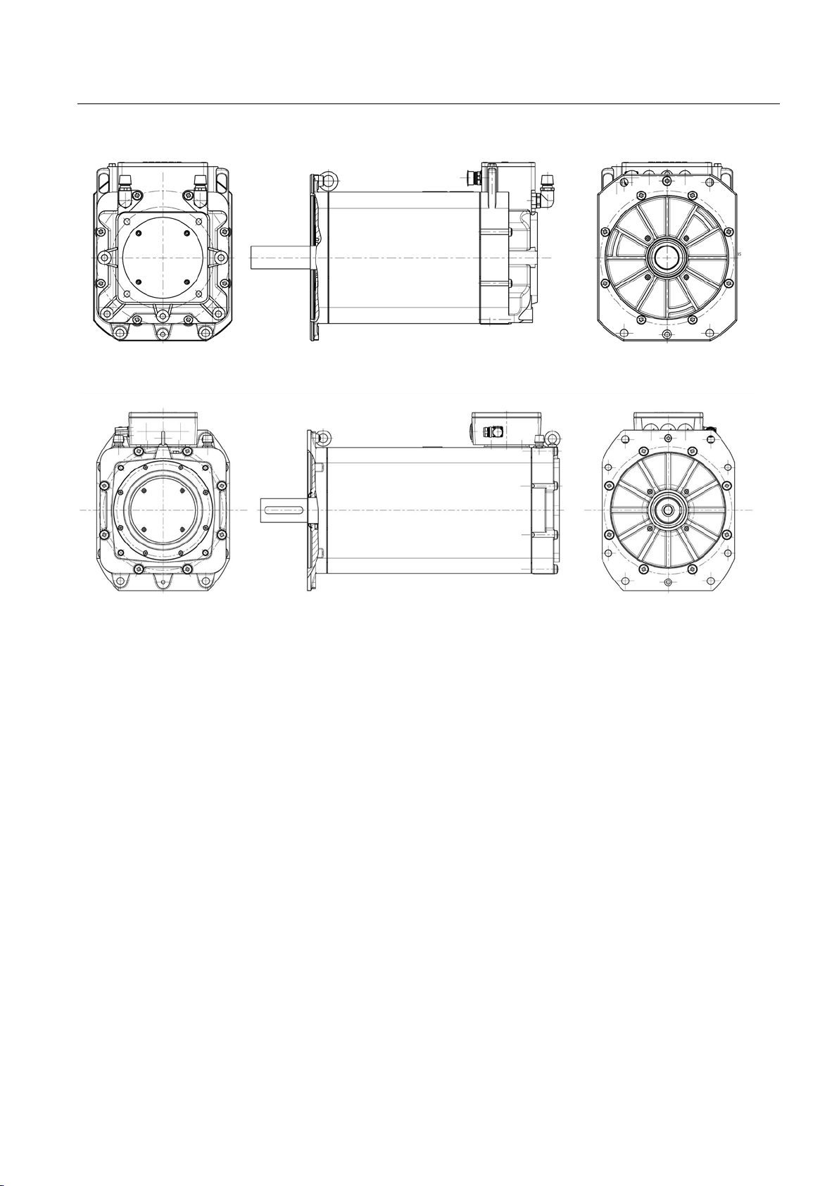
Figure 4-2 Arrangement of the lifting eyebolts for 1PV513x/1FV513x
Figure 4-3 Location of the lifting eyebolts for the 1FV516x
If you want to transport a motor that has already been in operation, proceed as follows:
1. Allow the motor to cool down.
2. Remove the connections provided by the customer.
3. Empty the motor of any cooling water and purge it carefully with air.
4. Close and seal all openings on the terminal box and housing.
5. Always transport and lift the motor by the lifting eyebolts on the bearing end shields.
SIMOTICS A-1FV5/1PV5 synchronous/induction motors
Operating Instructions, 03/2014, 610.45002.40
25
Page 26

Preparing for use
4.2.2
Storage
NOTICE
Seizure damage to bearings
Storing indoors
Protection against humidity
4.2 Transport and storage
The motors can be stored for up to 2 years in a dry, dust-free room that is not susceptible to
vibration (v
< 0.2 mm/s) without the specified storage time being reduced.
rms
If the motors are stored incorrectly, bearing seizure damage can occur (e.g. brinelling) as a
result of vibration.
● Apply a preservation agent (e.g. Tectyl) to bare, external components (e.g. shaft
extensions) if this has not already been carried out in the factory.
● Store the motor in an area that fulfills the following requirements:
– Dry, dust-free, frost-free and vibration-free The relative air humidity should be less
than 60 % and the temperature should not drop below -15 °C in accordance with
EN 60034-1.
– Well ventilated
– Offers protection against extreme weather conditions
– The air in the storage area must not contain any harmful gases.
● Protect the motor against shocks and humidity.
● Make sure that motor is covered properly.
● Avoid contact corrosion. You are advised to rotate the shaft extension manually every
three months.
If a dry storage area is not available, the following measures must be taken:
● Wrap the motor in humidity-absorbent material and then wrap it in film so that it is air
tight.
● Include several bags of desiccant in the seal-tight packaging. Check the desiccant and
replace as required.
● Place a humidity meter in the seal-tight packaging to indicate the level of air humidity
inside it.
● Inspect the motor on a regular basis.
SIMOTICS A-1FV5/1PV5 synchronous/induction motors
26 Operating Instructions, 03/2014, 610.45002.40
Page 27

Preparing for use
Long-term storage
Protecting the cooling-water system
4.2 Transport and storage
If you intend to place the motor in storage for longer than six months, you must check its
condition every six months.
● Check the motor for any damage.
● Carry out any necessary maintenance work.
● Document all preservation measures taken so that they can be reversed before the
machines are recommissioned.
● Make sure that storage area is air-conditioned.
When delivered, the cooling system is not filled with coolant.
When you place the motor in storage after use, drain the cooling water ducts and purge them
with air so that they are completely empty.
SIMOTICS A-1FV5/1PV5 synchronous/induction motors
Operating Instructions, 03/2014, 610.45002.40
27
Page 28

Preparing for use
4.2 Transport and storage
SIMOTICS A-1FV5/1PV5 synchronous/induction motors
28 Operating Instructions, 03/2014, 610.45002.40
Page 29
5
5.1
Installation
NOTICE
Temperature-sensitive parts
NOTICE
Shaft end
Note
Observe the technical data on the motor enclosure rating plates.
The following must be taken into account when the motors are installed
1PV513x/1FV513x
1FV516x
Radial force
1100 N
1800 N
Axial force (both directions)
700 N
1100 N
Some parts of the motor enclosure can reach temperatures that exceed 100 °C.
Temperature-sensitive components, e.g. cables etc., can be damaged if they come into
direct contact with the motor enclosure.
When locating temperature-sensitive components, ensure that they do not come into
contact with the motor enclosure.
When installing the motor, ensure that the end of the shaft is protected against blows and
pressure.
● Observe the data on the rating plate, as well as the warning and information plates on the
motor.
● The permissible cantilever and axial forces at the shaft end of the motors may not be
exceeded.
Table 5- 1 Permissible forces at the motor
● Check that they match the conditions (temperature, installation altitude) at the installation
location.
● Ensure that the end of the shaft is completely free of any anti-corrosion protection (use a
commercially available solvent).
● Ensure that the flange is in even contact with the mounting surface. When tightening the
fixing screws avoid any uneven stressing. Observe the tightening torques for the fixing
screws of the motor flange (see Fixing (Page 30) Table 5.2).
SIMOTICS A-1FV5/1PV5 synchronous/induction motors
Operating Instructions, 03/2014, 610.45002.40
29
Page 30

Mounting
5.2
Fixing
Mounting using the motor flange (flange mounting)
Note
When the motor is flange
specific natural mounting frequencies. In operation, this can result in excessive vibration.
To counter this, additional support can be provided at the NDE.
Ensur
Note
At the DE, only use screws with washer.
When mounting on an unsprung mass, always support at the NDE.
5.2 Fixing
● Rotate the drive elements by hand. If you hear any grinding noise, rectify the cause or
contact the manufacturer.
● Eyebolts that have been screwed in must either be tightened or removed after installation.
● The motors are to be installed in such a way that the coolant can freely flow in and out
unimpeded.
● Only remove all protective caps immediately before installing the respective parts.
To ensure smooth, vibration-free operation, the motor must be precisely aligned and the
components to be mounted on the shaft end correctly balanced.
-mounted, this creates a system that is capable of oscillation with
e that the motor is not subject to excessive tension.
SIMOTICS A-1FV5/1PV5 synchronous/induction motors
30 Operating Instructions, 03/2014, 610.45002.40
Page 31
Mounting
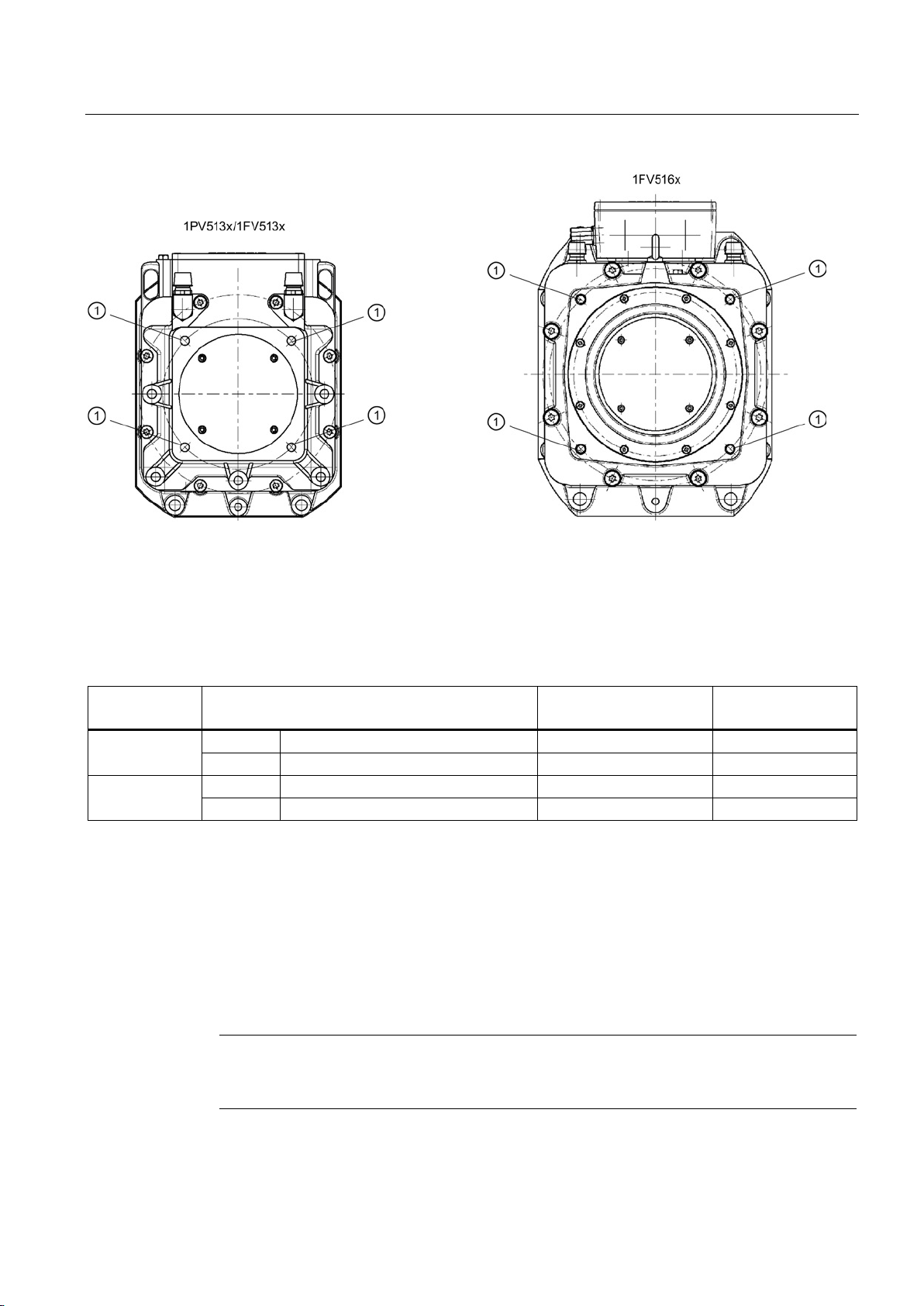
①
Thread for NDE support
Tightening torques
Motor
Screw
Tightening torque
±10 % [Nm]
Property class of the
screws
DE
M 12
85
8,8
NDE
M12 (screw-in depth, 25...30 mm)
85
8.8
DE
M 16
190
10.9
NDE
M12 (screw-in depth, 18...20 mm)
85
8.8
Alignment accuracy for coupling output
5.3
Attaching the output elements
Note
Do not subject the motor's shaft and bearings to impact. Do not exceed permissible
cantilever and radial forces.
5.3 Attaching the output elements
Figure 5-1 Motor support at the NDE
Table 5- 2 Tightening torques
1PV513x/
1FV513x
1FV516x
The maximum permissible concentricity deviation of the shafts of the motor and the driven
machine is 0.05 mm in the diameter.
SIMOTICS A-1FV5/1PV5 synchronous/induction motors
Operating Instructions, 03/2014, 610.45002.40
31
Page 32
Mounting
Balancing
Note
Note the designation of the balancing type on the shaft end face. Plain or toothed shaft ends
are not marked.
Pushing on the output elements
WARNING
Shock-hazard protection for output elements
5.3 Attaching the output elements
The motors are balanced so that when they are shipped, they correspond to vibration
severity grade A in accordance with EN60034-14 over the complete speed range.
The motors are fitted with a key; this means that they are dynamically balanced with half a
key. The balancing type is marked on the DE shaft end with "H" (half key).
● Make sure that the balancing method of the output element is correct! The output
elements must be balanced to balance quality grade G2.5 to ISO 1940. Rotary forces that
exceed this are not permissible. Please note that rotary forces can also occur with
coupling output.
● If the output element is shorter than the feather key with balancing method "H", the
section of the feather key that protrudes from the shaft contour and output element must
be removed to maintain the balance quality.
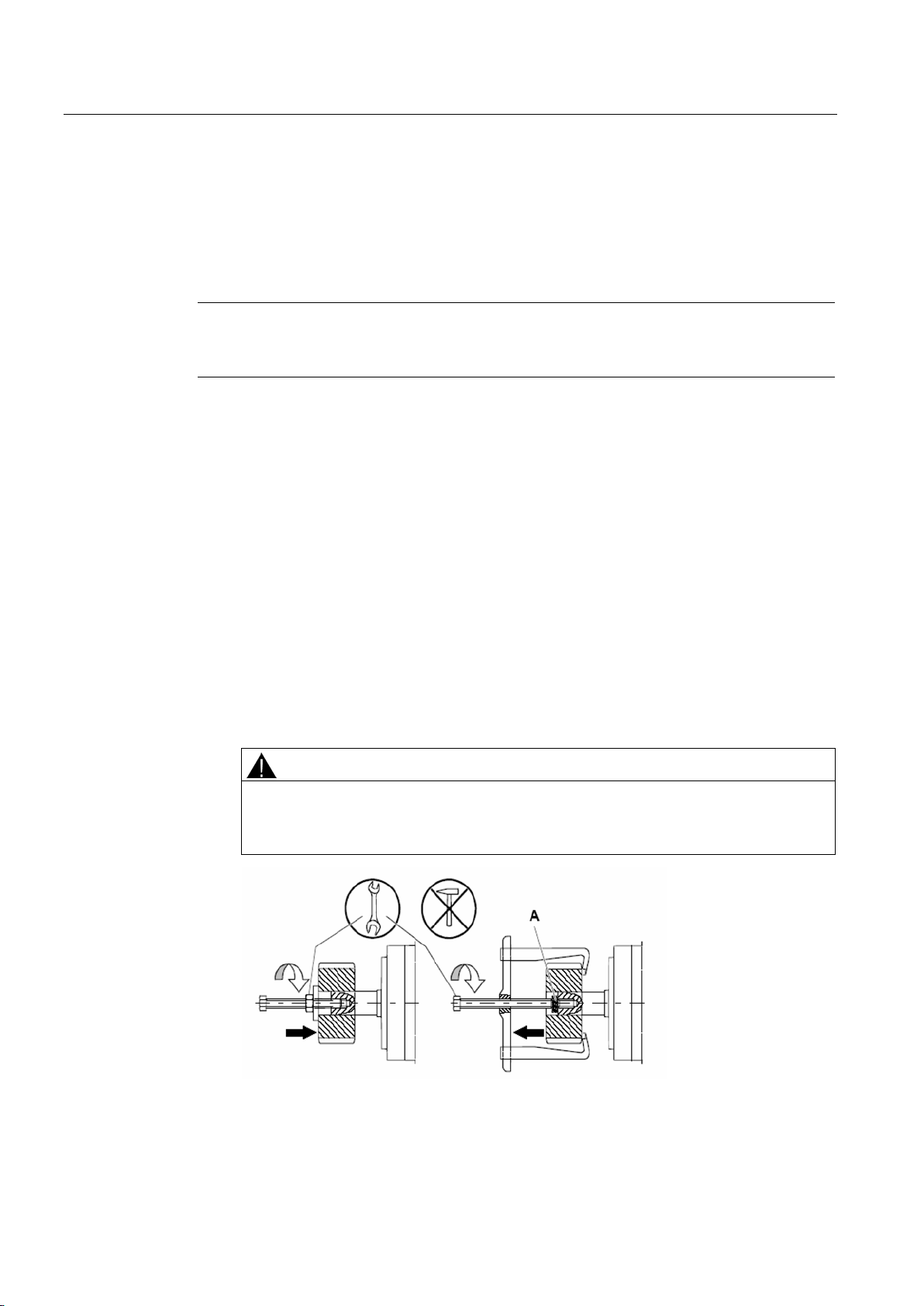
● Fit/remove the output elements only by means of suitable equipment:
– Use the threaded hole in the shaft extension (front).
– If necessary, heat up the output element.
– When removing output elements, use a washer to maintain the centering in the shaft
extension.
The general shock-hazard protection measures for output elements must be
observed.
Figure 5-2 Fitting/removing output elements; A = intermediate washer (for maintaining the
centering in the shaft extension)
SIMOTICS A-1FV5/1PV5 synchronous/induction motors
32 Operating Instructions, 03/2014, 610.45002.40
Page 33
Mounting
Motor without output element
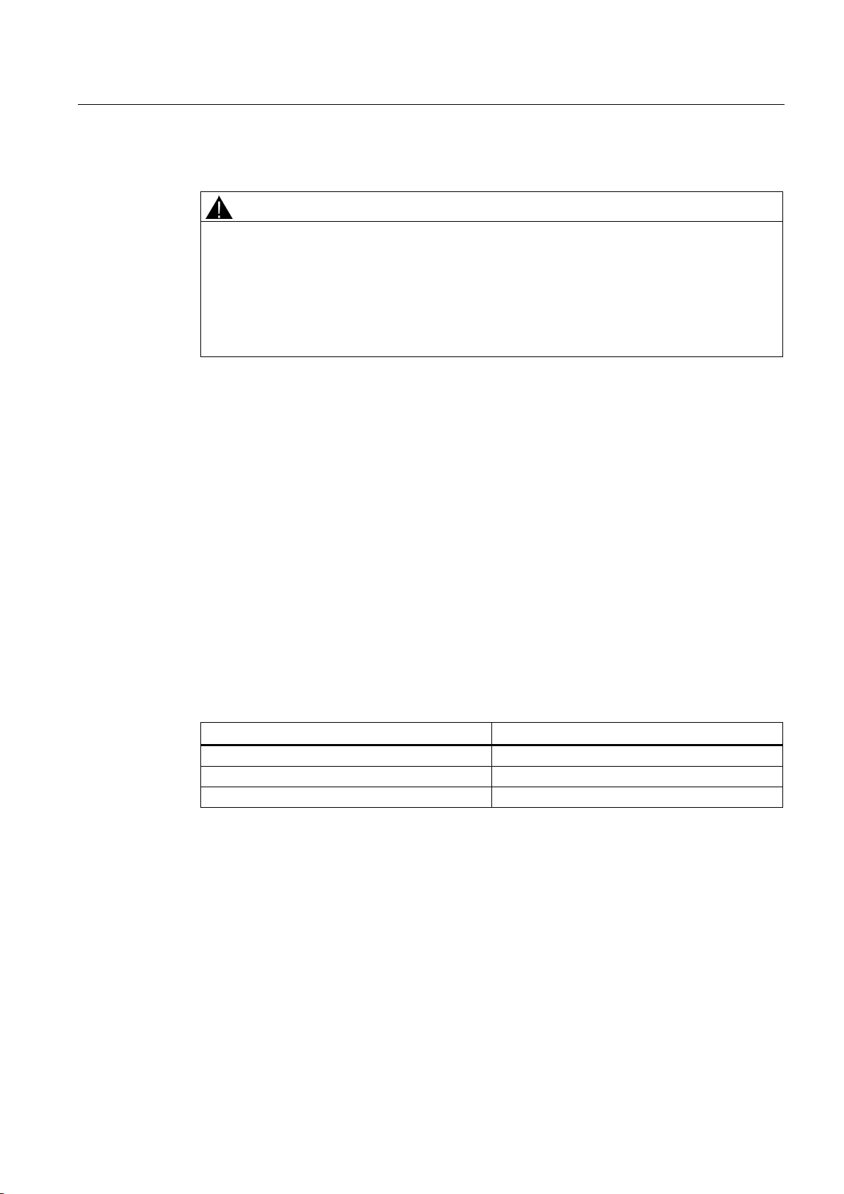
WARNING
The feather key can fall out
See also
5.4
Vibration load
Description
Vibration values
Vibration velocity v
according to ISO 10816
Max. 4.5 mm/s
Vibration acceleration a
peak
axial 1)
25 m/s2
Vibration acceleration a
radial 1)
50 m/s2
1) The measurement locations should be selected in accordance with ISO 10816-1 Paragraph 3.2.
5.4 Vibration load
The featherkeys are only secured during transport to prevent them from falling out. If a
motor is not equipped with an output element, the feather key may fall out during operation.
Death or serious injury can result.
At the shaft extension, secure the fitted key without output element so that it cannot be
flung out and for balance type "H" shorten it by approximately half.
Installation (Page 29)
The on-site system vibration characteristics depend on factors such as the output elements,
assembly conditions, alignment, installation, and external vibrations and can increase the
level of vibration on the motor.
Under certain circumstances, the rotor may have to be balanced completely with the output
element.
To ensure problem-free operation and a long service life, the vibration values specified to
ISO 10816 must not be exceeded at the defined measuring points on the motor.
Table 5- 3 Vibration values
rms
peak
SIMOTICS A-1FV5/1PV5 synchronous/induction motors
Operating Instructions, 03/2014, 610.45002.40
33
Page 34
Mounting
Note
Continuous operation within the natural frequency
Continuous operation within the natural frequencies of the mounted system should be
avoided. Generally, this results in permissible vibration values being exceeded, resulting in
damage to the system. To reduce vibration, flanged
the NDE.
5.4 Vibration load
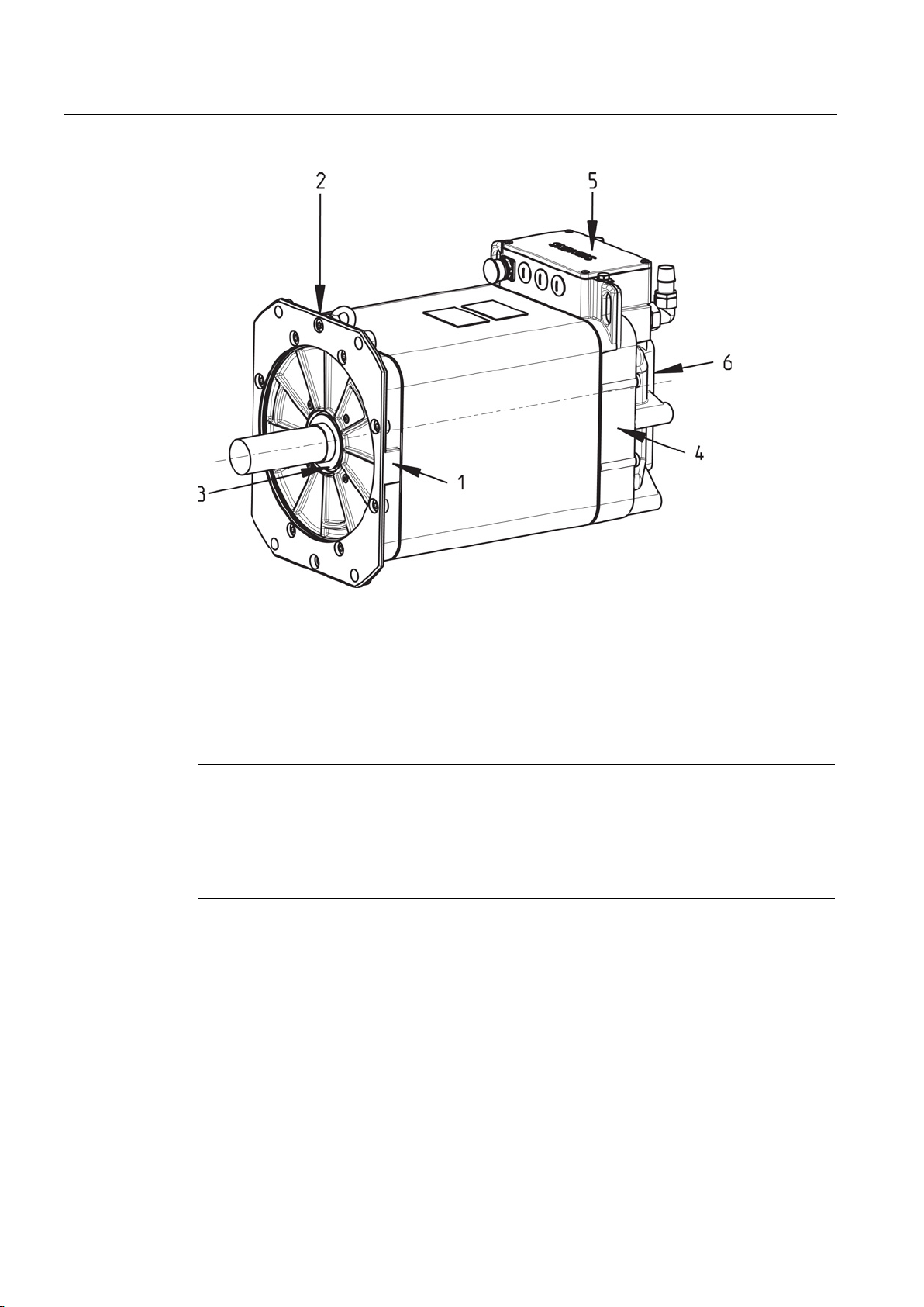
Figure 5-3 Vibration values at the measurement locations
The vibration acceleration must be evaluated in a frequency band of 10 to 2000 Hz.
The maximum peak value in the time range is to be considered.
To measure the vibration velocity, the measuring equipment must fulfill the requirements of
ISO 2954.
-mounted motors can be supported at
SIMOTICS A-1FV5/1PV5 synchronous/induction motors
34 Operating Instructions, 03/2014, 610.45002.40
Page 35
6
6.1
Mechanical connection of water cooling system
See also
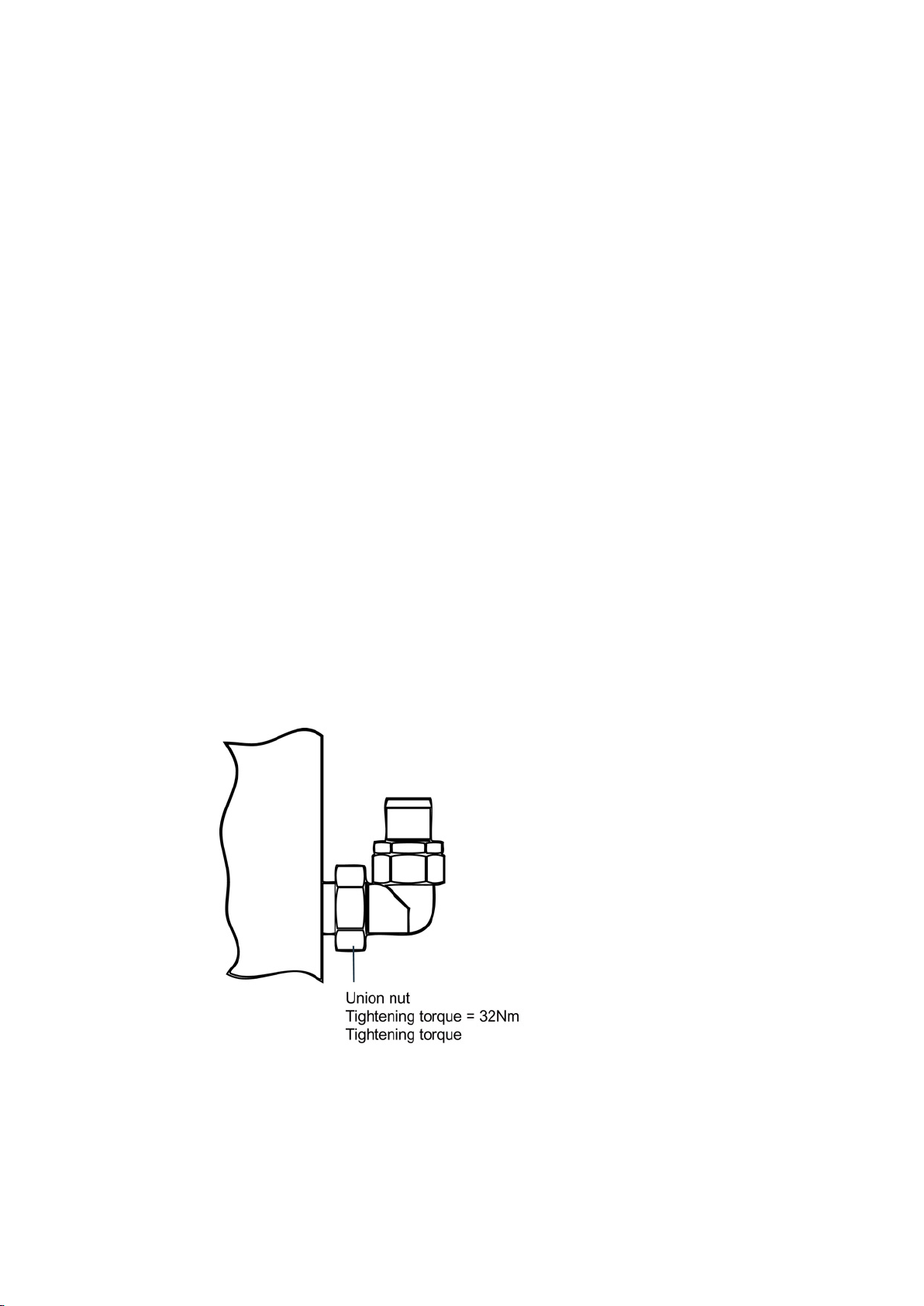
The inlet and outlet holes for the cooling water supply are located on the NDE in the bearing
shield.
1. Make sure that the cooling water fulfills the required cooling water specification, see the
chapter titled "Cooling".
2. Make sure that the appropriate volume of cooling water is available, see the rating plate
(type plate).
3. Attach the cooling water pipes to the cooling water connections. You can connect the inlet
and outlet as required.
4. Ensure that the maximum permissible operating pressure does not exceed 2.5 bar.
5. Ensure that the cooling water connections and the cooling water pipes are not subject to
continuous forces.
Adjusting the outlet direction of the cooling water connection:
1. Remove the union nut from the adjusting bracket
2. Rotate the adjusting bracket to the required output direction
3. Manually fix the adjusting bracket
4. Tighten the union nut to 32 Nm using a torque wrench
Cooling (Page 19)
SIMOTICS A-1FV5/1PV5 synchronous/induction motors
Operating Instructions, 03/2014, 610.45002.40
35
Page 36
Connection
6.2
Electrical connection
6.2.1
Safety information
DANGER
Risk of electric shock
DANGER
Motor damage warning
NOTICE
Electrostatically sensitive devices
6.2 Electrical connection
For synchronous motors, hazardous voltages are present at the motor terminals when the
rotors are rotating.
Only qualified personnel may perform work on the motor. The motor must be stationary,
isolated from the line supply and locked out so that it can be accidentally switched on.
This also applies to auxiliary circuits.
Converters and connectors must only be installed by properly trained personnel.
Regulations regarding work carried out in electrical installations must be observed.
The motor will be destroyed if it is directly connected to the three-phase line supply.
Only operate the motors with the appropriately engineered converters! Ensure the correct
phase sequence is used!
The motor contains electrostatic sensitive devices. Touching signal connections with
electrostatically charged hands or tools can result in malfunctions.
Note the ESD protection measures.
Safety rules for working on electrical installations in accordance with EN 50110-1:
● Disconnect the system.
● Protect against reconnection.
● Make sure that the equipment is de-energized.
● Ground and short-circuit.
● Cover or enclose adjacent components that are still live.
SIMOTICS A-1FV5/1PV5 synchronous/induction motors
36 Operating Instructions, 03/2014, 610.45002.40
Page 37
Connection
6.2.2
Cable entry and routing
Thread ∅
M6
M8
M10
Tightening torque [Nm]
4 ± 10 %
8 ± 10 %
13 ± 10 %
6.2 Electrical connection
● When selecting the required connecting cables, make sure that you take into account the
rated current and plant-specific conditions, such as ambient temperature, routing type,
etc. according to IEC / EN 60364-5-52 and IEC / EN 60204-1.
● Use EMC cable glands for permanently installed cable entries.
● Use shielded cables whose shields are conductively connected to a large area of the
terminal box of the motor using EMC cable glands. Make sure that the cable shields are
properly connected.
● Arrange the exposed connecting cables in the terminal box so that the PE conductor has
an excess length and the insulation of the cable conductors cannot be damaged.
● Only remove insulation from the cable ends so that the insulation reaches up to the cable
lug, terminal, or wire end ferrule.
● Adapt the size of the cable lugs or end sleeves in line with the dimensions of the terminal
board connections and the cross-section of the power cable (use parallel connecting
cables, if necessary).
● Make sure that the inside of the terminal box or connector is clean and free of cable
cuttings and moisture.
● Tighten all of the screws for the electrical connections (terminal board connections, with
the exception of the terminal strips) to the specified torque:
Table 6- 1 Tightening torques at the terminal board
● When connecting or changing internal connection cables, always observe the minimum
air clearance of 5.5 mm.
● Avoid protruding cable ends.
● Seal unused cable entries and screw in sealing elements so that they are secure and
airtight.
● Check seals and sealing surfaces of the terminal box or connector to ensure that the
degree of protection is maintained.
● Take measures to ensure that connecting cables cannot rotate, are not subject to strain
and pushing force and also provide anti-kink protection. It is not permissible to subject the
connector, the connecting bolts and cable glands to continuous force.
● The coding slot for the plug-in connections must be aligned when inserted into the socket
connector. The union nut must be tightened by hand up to the endstop.
● Plug in or remove the connector only when the system is de-energized.
SIMOTICS A-1FV5/1PV5 synchronous/induction motors
Operating Instructions, 03/2014, 610.45002.40
● The PE must be connected.
● The cable lugs of the power connections must extend directly to the cable lugs of the
motor winding connections. (see the diagram, "Attaching the cable lugs").
● It is not permissible to mark the cable connections using paint.
37
Page 38
Connection
6.2.3
Circuit diagram
Note
Cable outlet direction
If the direction of the cable outlet is not changed correctly, this can damage the connecting
cables. The direction of the cable outlet must not be changed as this invalidates warranty
claims.
6.2 Electrical connection
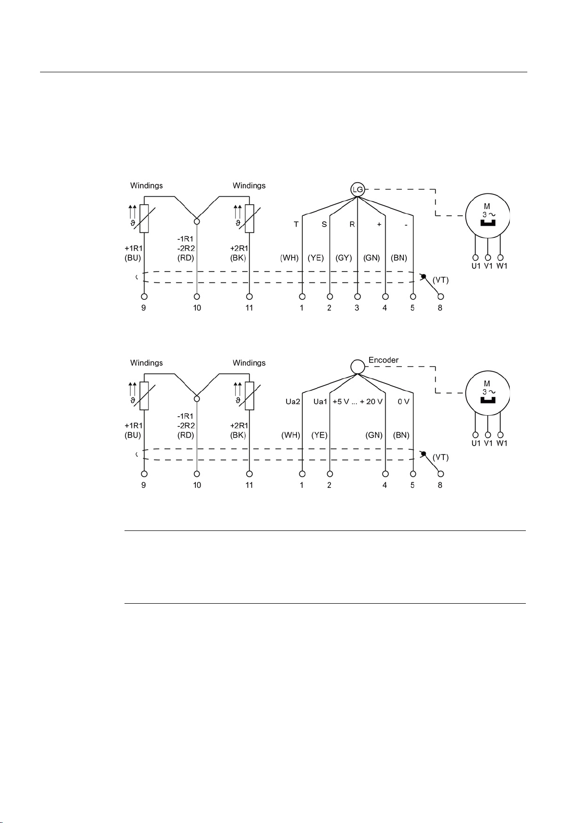
The circuit diagram contains information about the connection, connecting the motor winding
and signal lines.
Figure 6-1 Circuit diagram_1FV5 (without position encoder, contacts 1 ... 5 not assigned)
SIMOTICS A-1FV5/1PV5 synchronous/induction motors
38 Operating Instructions, 03/2014, 610.45002.40
Figure 6-2 Circuit diagram_1PV5 (without encoder, contacts 1 ... 5 not assigned)
Page 39
Connection
6.2.4
Terminal box
①
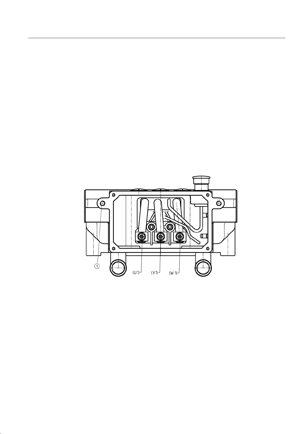
Ground conductor connection, M8
6.2 Electrical connection
● The motor connection depends on the desired direction of rotation, and is carried out as
follows:
– Clockwise direction of rotation when viewing the shaft extension:
Phase U1 connected to L1, V1 to L2 and W1 to L3
Signal Ua1 is received before Ua2.
– Counter clockwise direction of rotation when viewing the shaft extension:
Phase U1 connected to L3, V1 to L2 and W1 to L1
Signal Ua2 is received before Ua1
● Terminal assignment in the terminal box should be implemented as shown in the
following diagrams "Terminal box 1PV51xx/ 1FV51xx".
● Use cable lugs to DIN 46234.
● Screw the cover of the terminal box back on (tightening torque, 5 Nm).
Figure 6-3 Terminal box, 1PV513x/1FV513x
SIMOTICS A-1FV5/1PV5 synchronous/induction motors
Operating Instructions, 03/2014, 610.45002.40
39
Page 40
Connection
①
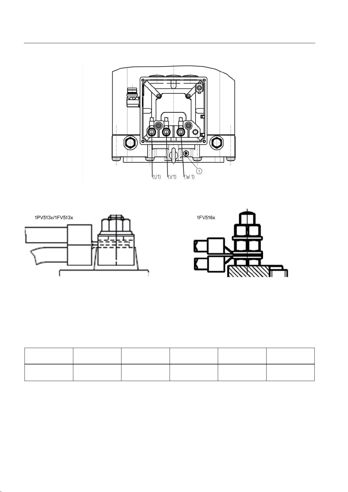
Ground conductor connection, M8
6.2.5
Data for electrical connection
Terminal box
Cable entry
(power)
Cable entry
(external signals)
Max. external
cable diameter 1)
Number of main
terminals
Cross-section per
terminal, max.
Grounding: 1 x M8
1) Dependent on the cable gland design
6.2 Electrical connection
Figure 6-4 1FV516x terminal box
Figure 6-5 Attaching cable lugs
Table 6- 2 1PV513x/1FV513x motors
Integrated in the
motor
SIMOTICS A-1FV5/1PV5 synchronous/induction motors
3 x PG16 1 x M23 15 mm Phases: 3 x M6
1 x 35 mm2
40 Operating Instructions, 03/2014, 610.45002.40
Page 41
Connection
Terminal box
Cable entry
(power)
Cable entry
(external signals)
Max. external
cable diameter 1)
Number of main
terminals
Cross-section per
terminal, max.
Grounding: 1 x M8
1) Dependent on the cable gland design
6.2.6
Signal connection
Pin
1PV5
1FV5
1PV5
without
encoder
1FV5
without
position
encoder
Connector
1
Signal Ua2
Signal T
Not assigned
2
Signal Ua1
Signal S
Not assigned
3
Not assigned
Signal R
Not assigned
4
Power supply
Not assigned
5
Grounding
Not assigned
6
- - -
-
7
- - -
- 8 - - -
-
9
KTY 84 + 1R1
10
KTY 84 -1R2/ -2R2
Note
•
•
•
6.2 Electrical connection
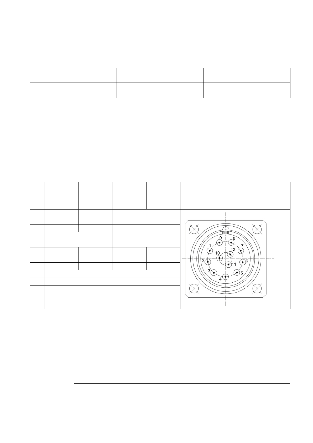
Table 6- 3 1FV516x motors
Gk420 3 x M32 x 1.5 1 x M23 27 mm Phases: 3 x M10
For the motors, the speed encoder and temperature sensor are connected using a 12-pin
connector, which is installed in the terminal box. Contact is established through the contact
pins. If the motors do not have an encoder, then only the temperature sensor signals are
assigned in the connector, as shown in the following table.
Table 6- 4 Signal connection, view of connector pins
1 x 70 mm2
11 KTY 84 +2R1
12 -
A suitable socket connector can be used to rotate the angle plug. Make sure that the
Removal, installation and adjustment of sensors only according to the corresponding
Only remove the protective cap from the angle connector immediately before inserting the
SIMOTICS A-1FV5/1PV5 synchronous/induction motors
Operating Instructions, 03/2014, 610.45002.40
socket connector is completely screwed on to avoid damaging the pin contacts.
instructions.
mating connector.
41
Page 42

Connection
6.2.7
Connecting the temperature sensor
6.2.8
Connecting the ground conductor
See also
6.2.9
Connecting-up a converter
Selecting and connecting the cables
6.2 Electrical connection
The temperature sensor is connected to the signal connector together with the speed
encoder signal.
The grounding conductor connection is located on the enclosure (see Fig. 6-3 and Fig. 6-4).
The grounding conductor connection must be in full compliance with the installation
regulation, e.g. according to IEC / EN 60204-1.
Terminal box (Page 39)
Use shielded connection cables to connect the motor to a converter. The cable shielding,
made up of many strands, must have a high electrical conductivity. Braided shields made of
copper or aluminum are well suited.
The shield must be connected at both ends to the motor and the converter; unshielded cable
ends must be kept as short as possible.
To ensure that high-frequency currents are effectively discharged, establish the shield
connection through the largest possible area, as 360° contact at the converter and at the
motor, e.g. using EMC glands at the cable entry points.
SIMOTICS A-1FV5/1PV5 synchronous/induction motors
42 Operating Instructions, 03/2014, 610.45002.40
Page 43
7
7.1
Measures prior to commissioning
Note
This list below does not claim to be complete. It may be necessary to perform additional
checks and tests in accordance with the specific, on
CAUTION
Thermal hazard: hot surfaces
Mechanical connection
Before commissioning the system, check that it is properly installed and connected. The
drive system must be commissioned as described in the operating instructions for the
converter/inverter.
-site situation.
The surface temperature of the motors can exceed 65 °C.
Do not touch hot surfaces.
If necessary, implement shock-hazard protection measures.
Temperature-sensitive parts (electric cables, electronic components) must not be placed on
hot surfaces.
The following conditions must be fulfilled and suitable for the operating conditions:
● All touch protection measures for moving and live parts must have been applied.
● The motor has been assembled and aligned properly.
● The rotor must be able to be manually rotated or using suitable equipment without coming
into contact with the stator.
● The operating conditions correspond to the data specified on the rating plate.
● All fixing screws, connecting elements, and electrical connections must be tightened and
properly implemented.
● The output elements have the proper setting conditions according to type, for example.
– Couplings are aligned and balanced.
– The belt tension is properly adjusted if a belt drive is used.
– Gear tooth flank play and gear tooth tip play as well as radial play are properly
adjusted if a gearwheel drive is used.
SIMOTICS A-1FV5/1PV5 synchronous/induction motors
Operating Instructions, 03/2014, 610.45002.40
43
Page 44
Commissioning
Note
If changes occur with respect to normal operation (e.g. increased temperatures, noise
or oscillation), if in doubt, switch off the motor. Determine the cause and if necessary
consult the manufacturer. Even in test operation, never disable protective functi
devices.
Electrical connection
CAUTION
Monitoring equipment
Liquid cooling
Note
Venting
The
7.1 Measures prior to commissioning
ons or
● The motor is connected so that it rotates in the direction specified.
● The minimum insulation resistance values are maintained.
● The grounding and equipotential bonding connections have been established correctly.
● The indicated speed limit n
● Appropriately configured control and speed monitoring functions ensure that the motor
cannot exceed the permissible speeds specified on the rating plate.
● The temperature sensors for the motor monitoring devices have been correctly connected
and are fully functional.
If liquid cooling is used, the coolant supply must be connected and ready for operation. The
coolant circulation (flow rate, temperature) complies with requirements.
is not exceeded during operation on a converter.
max
If the speed n
is exceeded, this can damage the bearings, short-circuiting rings, press
max
fits, etc. To ensure that the motor does not run at excessive speeds, the controller must
configured accordingly or speed monitoring must be activated in the drive system.
cooling circuit must be vented before commissioning.
SIMOTICS A-1FV5/1PV5 synchronous/induction motors
44 Operating Instructions, 03/2014, 610.45002.40
Page 45
Commissioning
Roller bearings
Note
Unfavorable conditions
If the motor was stored under unfavorable conditions, the bearings need to be replaced after
approx. 18 months.
7.2
Performing a trial run
WARNING
Danger from rotating rotor
7.3
Checking the insulation resistance
WARNING
WARNING
Danger! High voltage
7.2 Performing a trial run
If the motor has been stored under favorable conditions (i.e. in a dry, dust-free room that is
not susceptible to vibration) for more than three years, the bearings must be replaced.
Implement shock-hazard protection measures for output elements. Take suitable measures
to ensure that feather keys (if used) cannot fall out.
After long storage or shutdown periods, the insulation resistance of the windings must be
measured to ground with direct voltage.
Work on power installations must only be carried out by specialists. Before measuring the
insulation resistance, read the manual for the insulation resistance meter you are going to
use.
During and immediately after the measurement, hazardous voltage levels may be present.
Touching live components can be result in death or serious injury.
Never touch the terminals when measuring or immediately after the measurement.
Check the connected supply feeder cables to ensure that the line supply voltage cannot be
connected.
SIMOTICS A-1FV5/1PV5 synchronous/induction motors
Operating Instructions, 03/2014, 610.45002.40
45
Page 46
Commissioning
Limits
Rated voltage UN < 2 kV
Measurement voltage
1000 V (minimum, 100 V)
windings
time
Note
Cleaning and/or drying the windings when reaching critical insulation resistance
If the critical insulation resistance is less than or equal to this value, the windings must be
dried or, if the fan is removed, cleaned thoroughly and dried.
Note that the in
windings. The insulation resistance can only be evaluated accurately when measured on
a winding that has been cooled down to room temperature (approx. 20 to 30
Note
Measured value close to critical value
If the measured value is close to the critical value, the insulation resistance should be
subsequently checked at suitably regular intervals.
Values apply for measurement at a winding temperature of 25 °C.
7.3 Checking the insulation resistance
● Always measure the insulation resistance of the winding to the motor enclosure when the
winding temperature is between 20 and 30 °C.
● When performing the measurement, wait until the final resistance value is reached
(this takes approx. one minute).
The table below specifies the measuring circuit voltage as well as the limit values for the
minimum insulation resistance and the critical insulation resistance with a rated motor
voltage of U
Table 7- 1 Stator winding insulation resistance at 25 °C
< 2 kV:
N
Minimum insulation resistance for new, cleaned or repaired
Critical specific insulation resistance after a long operating
10 MΩ
0.5 MΩ/kV
Note the following:
● Dry, new windings have an insulation resistance of between 100 and 2000 MΩ
(sometimes higher).
An insulation resistance value close to the minimum value could be due to moisture
and/or dirt accumulation.
● The insulation resistance of the motor winding can drop during the course of its service
life can drop due to ambient and operational influences. The critical insulation resistance
for a temperature of 25 °C on the winding can be calculated by multiplying the rated
voltage (kV) by the specific critical resistance value (0.5 MΩ/kV);
Example: Critical resistance for a rated voltage (V
) of 0.6 kV:
N
0.6 kV x 0.5 MΩ/kV = 0.3 MΩ
sulation resistance of dried, clean windings is lower than that of warm
SIMOTICS A-1FV5/1PV5 synchronous/induction motors
46 Operating Instructions, 03/2014, 610.45002.40
°C).
Page 47
Commissioning
7.4
Switching on the motor
NOTICE
Operation noise or abnormal noises
CAUTION
Note the maximum rotational speed
7.5
Liquid cooling
NOTICE
WARNING
Risk of burning from hot steam
7.4 Switching on the motor
Before you switch on the motor, ensure that the parameters of the frequency converter have
been assigned correctly.
The motor can be damaged by improper handling during transport, storage, or setup. If a
damaged motor is operated, this can damage the winding or bearings and could even
destroy the system.
If the motor is not running smoothly or is emitting abnormal noises, shut the motor down
and try to determine the cause of the fault as it runs down.
The maximum rotational speed n
is the highest permissible operating speed.
max
The maximum speed is specified on the rating plate.
If the speed n
is exceeded, this can damage the bearings, short-circuiting rings, press
max
fits, etc. To ensure that the motor does not run at excessive speeds, the controller must
configured accordingly or speed monitoring must be activated in the drive system.
The motor must always be connected to the cooling water supply when in operation.
If the cooling water supply fails or the motor is operated for a short time without cooling
water, this can cause it to overheat. This can result in material damage or destroy the motor
completely.
Never operate the motor without the cooling water supply. Monitor the permissible water
inlet temperatures.
When cooling water enters the hot motor, this immediately generates hot steam that
escapes under high pressure. The cooling water system can burst. This can result in death,
serious injury or material damage.
Do not connect the cooling water supply until the motor has cooled down.
SIMOTICS A-1FV5/1PV5 synchronous/induction motors
Operating Instructions, 03/2014, 610.45002.40
47
Page 48

Commissioning
7.5 Liquid cooling
SIMOTICS A-1FV5/1PV5 synchronous/induction motors
48 Operating Instructions, 03/2014, 610.45002.40
Page 49
8
8.1
Safety instructions during operation
WARNING
Do not remove covers when motor is running
WARNING
Faults during operation
CAUTION
Danger of burns
Rotating or live parts are dangerous. Death, serious injury, or material damage can result if
the required covers are removed.
All covers that prevent operators from coming into contact with active or rotating parts,
ensure compliance with the required degree of protection, or ensure proper air guidance
and, in turn, effective cooling must not be opened/removed during operation.
Deviations from normal operation (e.g. increased power consumption, temperatures or
vibrations, unusual noises or odors, tripping of monitoring devices, etc.) indicate that the
machine is not functioning properly. This can cause faults that can result in eventual or
immediate death, serious injury, or material damage.
Inform maintenance personnel immediately. If in doubt, shut down the motor immediately,
taking into account the plant-specific safety regulations.
The temperature of certain parts of the motor can exceed 65 °C. Physical contact with the
machine could cause serious burns.
Check the temperature of the parts before touching them and take appropriate protective
measures if necessary.
SIMOTICS A-1FV5/1PV5 synchronous/induction motors
Operating Instructions, 03/2014, 610.45002.40
49
Page 50

Operation
8.2
Stoppages
Measures for operational motors during stoppages
Note
Damage due to improper storage
The motor can be damaged if it is not stored properly.
If the motor is out of service for extended periods of time, implement suitable anti
corrosion, preservation, and drying measures.
W
recommended in "Commissioning".
8.3
Shutdown
Measures during shutdown
8.4
Faults
Note
Damage to the machine caused by faults
Correct the cause of the fault as specified in the remedial measures section. Repair any
damage to the machine/motor that might have occurred.
Note
When operating the motor with a converter, refer also to the operating instructions of the
frequency converter if electrical faults occur.
8.2 Stoppages
● If the motor is out of service for extended periods of time, run it at regular intervals
(roughly once a month) or at least spin the rotor.
● Refer to the section "Energizing" before restarting the motor.
-
hen restarting the motor after a long shutdown period, carry out the measures
● When switching off the motor, refer to the operating instructions for the converter.
● Switch off the cooling water supply if the standstill period is expected to be lengthy.
If there are deviations from normal operation or if faults occur, initially proceed according to
the following list. In this regard, observe the relevant chapters in the documentation
associated with the components of the complete drive system.
Even in test operation, never disable protective functions or devices.
SIMOTICS A-1FV5/1PV5 synchronous/induction motors
50 Operating Instructions, 03/2014, 610.45002.40
Page 51
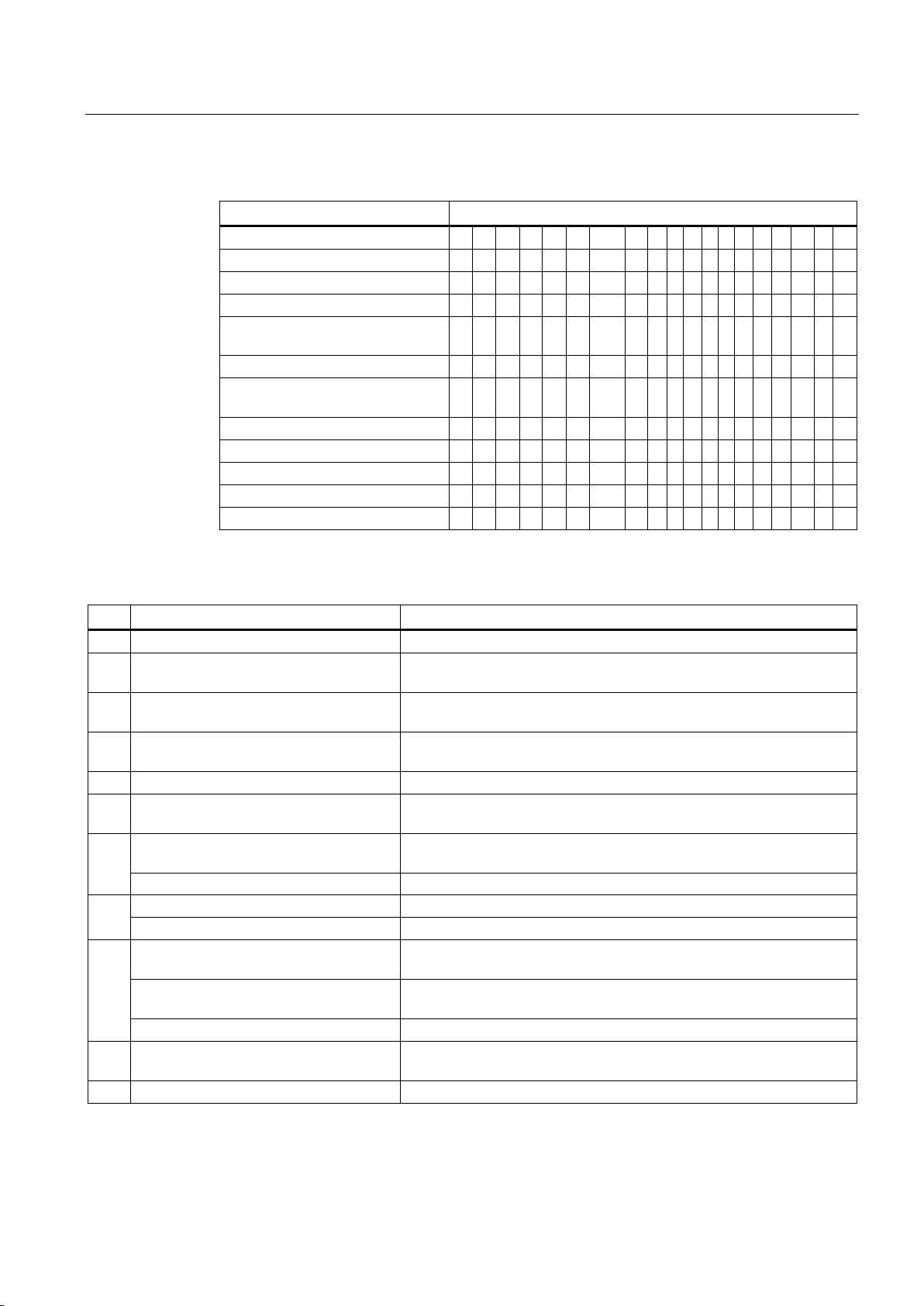
Operation
Fault
Cause of fault (see key table)
Motor does not start up
A B E
Motor starts up slowly
A C E F
Rumbling noise during startup
C E F
Rumbling noise during operation
A C E F
operation
Overheating with load
A C G H I
winding sections
Uneven running
J K
Grinding sound, running noise
L
Radial vibrations
M N O P R
Axial vibrations
O Q R
Water is escaping
S
No.
Cause of fault
Remedial measures
A
Overload
Reduce load
cable
frequency too low
Check the settings on the frequency converter, perform automatic motor
identification
E
Stator winding incorrectly connected
Check winding connections
circuit in stator winding
Measure the winding resistances and insulation resistances, repair after
consultation with manufacturer
off
Water connection / pipes defective
Locate leaks and seal as necessary, or consult the manufacturer
Cooling water flow rate too low
Increase cooling water flow rate
Inlet temperature too high
Set correct inlet temperature
in and out unimpeded
foreign bodies
unimpeded
Fan motor does not start up
Make sure that the fan motor works properly
encoder cable
K
Excessive drive controller gain
Adjust the controller
8.4 Faults
Table 8- 1 Possible faults
Overheating during no-load
Overheating of individual
D G H I
E F
Table 8- 2 Key to causes of faults and remedial measures
B Interruption of a phase in the supply
C Interruption of a phase in the supply after
Check frequency converter and supply cables
Check frequency converter and supply cables
switching on
D Converter output voltage too high,
F Winding short circuit or phase short
G Cooling water not connected / switched
Check cooling water connection / switch on cooling water
H
I Heat dissipation impeded by deposits Clean the surface of the drives and ensure that the cooling air can flow
Cooling air inlet/outlet is blocked by
J Insufficient shielding for motor and/or
SIMOTICS A-1FV5/1PV5 synchronous/induction motors
Operating Instructions, 03/2014, 610.45002.40
Remove the block and ensure that the cooling air can flow in and out
Check the shielding and grounding
51
Page 52

Operation
No.
Cause of fault
Remedial measures
Rotating parts are grinding
Determine cause and adjust parts
Foreign bodies within the motor
Send to manufacturer for repair
Bearing damage
Send to manufacturer for repair
M
Rotor not balanced
Decouple rotor and rebalance
N
Rotor out of true, shaft bent
Consult the manufacturer
O
Poor alignment
Align motor unit, check coupling
P
Coupled machine not balanced
Re-balance coupled motor
Q
Shocks from coupled machine
Check coupled motor
R
Imbalance originating from gearing
Adjust/repair gearing
defective
8.4 Faults
L
S Cooling water pipe / water connection
If the fault still cannot be resolved after applying the measures specified above, please
contact the manufacturer or the Siemens Service Center.
Locate leaks and seal as necessary, or consult the manufacturer
SIMOTICS A-1FV5/1PV5 synchronous/induction motors
52 Operating Instructions, 03/2014, 610.45002.40
Page 53
9
9.1
Safety information
DANGER
Risk of electric shock from touching live parts
WARNING
Danger of burns
If you are unclear about anything, consult the manufacturer, specifying the motor type and
serial number, or arrange for the maintenance work to be carried out by one of the Siemens
Service Centers.
For synchronous motors, hazardous voltages are present at the motor terminals when the
rotors are rotating.
Live electrical parts are dangerous. Touching these parts will result in an electric shock,
which in turn causes death or serious injury.
Before starting work on the machines, make sure that the plant or system has been
disconnected in a manner that is compliant with the appropriate specifications and
regulations. In addition to the main currents, make sure that supplementary and auxiliary
circuits, particularly in heating devices, are also disconnected.
Note all the information provided in "Safety information and application information" in these
operating instructions and ensure that only persons who have the necessary know-how are
entrusted to carry out work on power installations.
Some parts of the enclosure of electrical machines can reach temperatures in excess
of 65 °C.
Touching components when the machine is in operation can cause severe burns.
Do not touch frame parts while the machine is in operation or immediately after machine
operation. Allow frame parts to cool off before starting any work.
SIMOTICS A-1FV5/1PV5 synchronous/induction motors
Operating Instructions, 03/2014, 610.45002.40
53
Page 54
Service and maintenance
Safety regulations
Other safety-related measures
NOTICE
Personal protective equipment when using chemical cleaning agents
CAUTION
Personal protective measures when working with compressed air
Qualified personnel
9.1 Safety information
Before starting maintenance work, always observe the five safety rules.
1. Disconnect the system.
2. Protect against reconnection.
3. Make sure that the equipment is de-energized.
4. Ground and short-circuit.
5. Cover or enclose adjacent components that are still live.
These measures described above must not be reversed until the maintenance work has
been completed and the motor fully assembly again.
Chemical cleaning agents can be caustic or emit dangerous fumes.
If these come into contact with skin or if you inhale the fumes, this can cause injuries
(e.g. chemical burns on the skin or respiratory passages, or skin irritation).
During cleaning, make sure that appropriate methods of extracting fumes are in place and
that you wear the appropriate protective gear (e.g. gloves, goggles, face masks).
If using chemical cleaning agents, observe the instructions and any warnings provided in
the relevant safety data sheet. Chemical cleaning agents must be suitable for use with the
machine's components, particularly where plastic components are concerned.
When you clean using compressed air, this can stir up dust, metal chips, or cleaning
agents, Personal injury will result.
When cleaning using compressed air, make sure you use suitable extraction equipment
and wear protective equipment (safety goggles, protective suit, etc.).
This machine must be commissioned and operated by qualified personnel only. For the
purpose of the safety information in these Operating Instructions, a "qualified person" is
someone who is authorized to energize, ground, and tag equipment, systems, and circuits in
accordance with established safety procedures.
SIMOTICS A-1FV5/1PV5 synchronous/induction motors
54 Operating Instructions, 03/2014, 610.45002.40
Page 55
Service and maintenance
Safety notes
WARNING
Rotating or live parts
WARNING
Transportation in accordance with proper procedures
9.2
Maintenance intervals
General
Note
Inspection if there are faults or unusual conditions
Unusual condi
three
the machine.
If there are faults or unusual conditions such as overload or short circuit
inspect the motor.
Measures, inspection/maintenance intervals
9.2 Maintenance intervals
Rotating or live parts are dangerous. Death, serious injury, or material damage can result if
the required covers are removed or if the device is not operated properly.
Before starting work on the motor and, in particular, before opening the covers of live parts,
make sure that the motor or system is properly isolated.
Only transport the motor in accordance with the transport guidelines. Death, serious injury,
or material damage can result if the motor is not transported properly.
Whenever you have to transport the motor, follow the instructions provided in the section
"Transport and storage".
Within the scope of the bearing change intervals, the motors are maintenance-free within the
specified usage time.
Careful and regular maintenance, inspections, and overhauls are essential for detecting and
eliminating faults in good time before they can cause any damage.
tions or faults that represent electrical or mechanical overstressing of the
-phase motor, such as overload, short circuit, etc. can cause consequential damage to
Operating conditions and characteristics can vary widely. For this reason, only general
maintenance intervals can be specified here.
etc. immediately
● Maintenance intervals should, therefore, be scheduled to suit the local conditions, such
as pollution/dirt, switching frequency, load, etc.
SIMOTICS A-1FV5/1PV5 synchronous/induction motors
Operating Instructions, 03/2014, 610.45002.40
55
Page 56

Service and maintenance
9.3
General inspection guidelines
NOTICE
9.4
Bearing replacement intervals
9.3 General inspection guidelines
When inspecting a motor, you do not generally need to dismantle it. The motor only be
dismantled if the bearings need to be replaced.
While the motor is running, check that:
● The smooth running characteristics and machine running noise have not deteriorated.
● The cooling water system is not leaking.
Once the machine has been shut down, check that:
● All the fixing bolts/screws for the mechanical and electrical connections have been
securely tightened.
If you identify any problems during the inspection, rectify them immediately. Otherwise
the machine may be damaged.
The bearings are subject to wear and must be replaced after a defined number of operating
hours. For average load levels, the bearings must be replaced after approx. 20,000 h,
however, at the latest after 5 calendar years. The address for service & support is provided
in the Appendix under Siemens Service Center.
SIMOTICS A-1FV5/1PV5 synchronous/induction motors
56 Operating Instructions, 03/2014, 610.45002.40
Page 57
10
10.1
Decommissioning
WARNING
Machine parts can fall
10.2
Disposal
Disassembly of the machine must be carried out and/or supervised by qualified personnel
with appropriate expert knowledge.
1. Contact a certified waste disposal organization in your vicinity. Clarify what is expected in
terms of the quality of dismantling the machine and provision of the components.
2. Follow the five safety rules.
3. Disconnect all electrical connections.
4. Remove all liquids such as oil, water, …
5. Remove all cables.
6. Release the motor mounting.
7. Transport the machine to a suitable location for disassembly.
Dismantle the machine using the general machine-typical procedures.
The machine is made up of heavy parts. These parts can fall during dismantling. This can
result in death, serious injury or material damage.
Secure the machine parts being dismantled to prevent them falling.
The motors must be disposed of in accordance with domestic and local regulations as part of
the standard recycling process or they can be returned to the manufacturer.
The encoder electronics must be properly disposed of as electronic waste.
Protecting the environment and preserving its resources are corporate goals of the highest
priority for us. Our worldwide environmental management system to ISO 14001 ensures
compliance with legislation and sets high standards in this regard. Environmentally friendly
design, technical safety and health protection are always firm goals even at the product
development stage.
SIMOTICS A-1FV5/1PV5 synchronous/induction motors
Operating Instructions, 03/2014, 610.45002.40
Recommendations for the environmentally friendly disposal of the machine and its
components are given below. Be sure to comply with local disposal regulations.
57
Page 58

Decommissioning and disposal
Components
Process materials and chemicals
Insulating materials
Disposing of permanent magnets
10.2 Disposal
Sort the components for recycling according to whether they are:
● Electronics waste, e.g., sensor electronics
● Iron to be recycled
● Aluminum
● Non-ferrous metal, e.g., motor windings
● Insulating materials
Sort the process materials and chemicals for recycling according to whether they are:
● Oil
Dispose of the spent oil as special waste in accordance with the spent oil ordinance.
● Grease
● Solvents
● Cleaner solvent
● Paint residues
Do not mix solvents, cleaner solvents and paint residues.
Electrical insulation materials are mainly used in the stator. Some supplementary
components are made of similar materials and must, therefore, be handled in the same
manner. The insulating materials in question are used on the following items of equipment:
● Various insulators, which are used in terminals boxes
● Voltage and current transformers
● Electric cables
● Instrument wiring
● Surge arrester
● Capacitors
Permanent magnets must be demagnetized prior to disposal. This helps avoid potential
hazards caused by permanent magnets during and after disposal. Permanent magnets are
heated to demagnetize them.
SIMOTICS A-1FV5/1PV5 synchronous/induction motors
58 Operating Instructions, 03/2014, 610.45002.40
Page 59

Decommissioning and disposal
NOTICE
Removing the rotor
10.2 Disposal
Permanent magnets can be demagnetized in one of the following ways:
● Arrange for the entire machine to be subject to thermal treatment by a specialist disposal
company.
● Return the machine to the manufacturer who can then remove and demagnetize the rotor
and/or permanent magnets. Rotors that are still installed and have not been
demagnetized must not be transported.
It is only permissible that the manufacturer removes a permanent magnet rotor. Contact the
Siemens Service Center (Page 62) if necessary.
SIMOTICS A-1FV5/1PV5 synchronous/induction motors
Operating Instructions, 03/2014, 610.45002.40
59
Page 60

Decommissioning and disposal
10.2 Disposal
SIMOTICS A-1FV5/1PV5 synchronous/induction motors
60 Operating Instructions, 03/2014, 610.45002.40
Page 61

A
A.1
List of abbreviations
Abbreviation
Meaning
ABS
Acrylonitrile-butadiene-styrene
BGR
Rules of the German Trade Association
BGV
Regulations of the German Trade Association
DE
Drive end
Standard)
EC
European Community
ESD
Electrostatically sensitive devices
EMC
Electromagnetic compatibility
EN
Euro-Norm
EPDM
Ethylene-propylene-diene-rubber
H
Halfkey balancing
IEC
International Electrotechnical Commission
IM
Type of construction
IP
International Protection
ISO
International Organization for Standardization
LG
Position encoder
NDE
Non-drive end
NN
Normal zero
PVC
Polyvinyl chloride
RPE
Rotor position encoder
UL
Underwriters Laboratories
DIN Deutsche Industrie Norm (German Industry
KTY Temperature sensor
MLFB Machine-readable product code
SIMOTICS A-1FV5/1PV5 synchronous/induction motors
Operating Instructions, 03/2014, 610.45002.40
61
Page 62

Appendix
A.2
Siemens Service Center
A.2 Siemens Service Center
If you have any questions relating to repair or spare parts, please contact your local Siemens
office.
For more information, go to the Internet address:
http://www.siemens.com/automation/service&support .
There, you can find Siemens contacts worldwide for information about specific technologies.
Wherever possible, you will find a local contact partner for:
● Technical support
● Spare parts/repairs
● Service
● Training
● Sales
● Technical support/engineering
You start by selecting
● a country
● a product or
● a sector
Once the remaining criteria have been laid down, the required contact will be shown along
with the associated area of expertise.
SIMOTICS A-1FV5/1PV5 synchronous/induction motors
62 Operating Instructions, 03/2014, 610.45002.40
Page 63
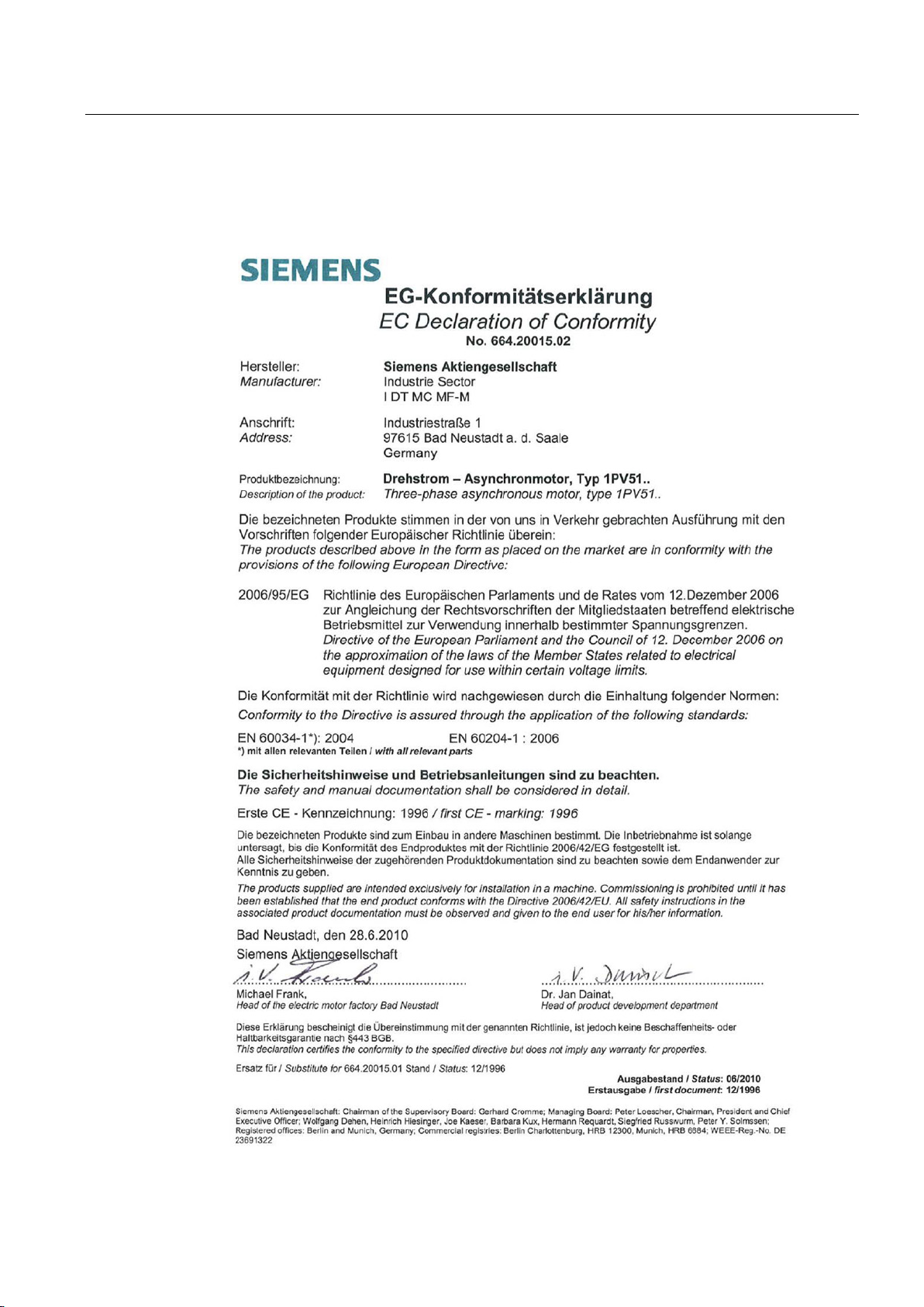
Appendix
A.3
Declaration of conformity
A.3 Declaration of conformity
SIMOTICS A-1FV5/1PV5 synchronous/induction motors
Operating Instructions, 03/2014, 610.45002.40
63
Page 64
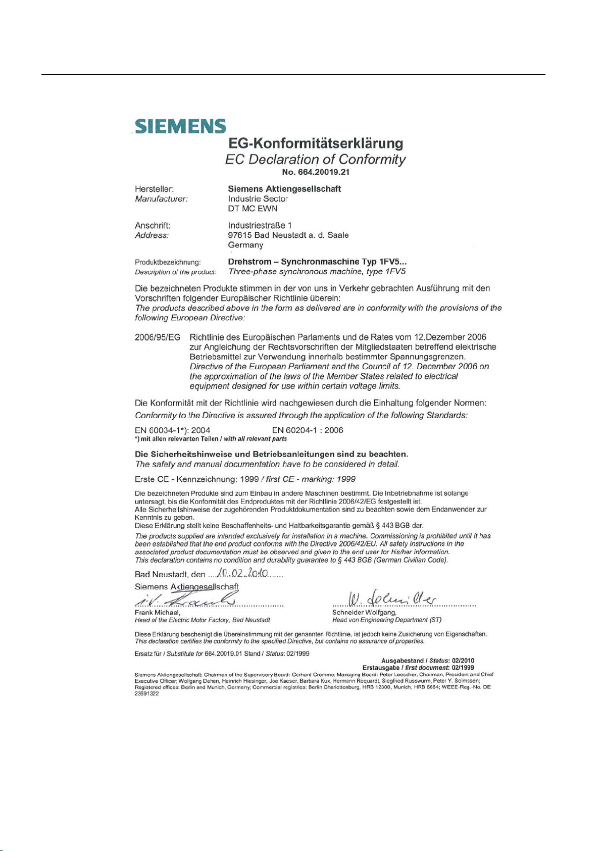
Appendix
A.3 Declaration of conformity
SIMOTICS A-1FV5/1PV5 synchronous/induction motors
64 Operating Instructions, 03/2014, 610.45002.40
Page 65

A
C
D
E
F
I
M
O
R
S
T
V
Ambient conditions, 19
Circuit diagram, 38
Commissioning, 43
Connection
Electrical, 36
Mechanical, 35
Connection of the liquid cooling, 35
Declaration of conformity, 63
Degree of protection, 18
Electrical connection, 36
ESD guidelines, 13
Faults, 50
Flange mounting, 30
Rating plate, 16
Regulations, 18
Safety information, 9
Shutdown, 50
Siemens Service Center, 62
Storage, 26
Terminal box, 39
Tightening torques
Electrical connections, 37
Transportation, 23
Types of construction, 18
Vibration load, 33
Vibration values, 33
Inspection and maintenance, 53
Maintenance intervals, 55
Mounting the motor, 30
Output elements, 32
SIMOTICS A-1FV5/1PV5 synchronous/induction motors
Operating Instructions, 03/2014, 610.45002.40
65
Page 66

 Loading...