

Siemens SIMOTICS DP, SIMOTICS SD, SIMOTICS 1LP, SIMOTICS 1PC, SIMOTICS 1PF Compact Operating Instructions
...Page 1
Contents Equipment manua ls K230F
No.
Equipment
Manufacturer
Document
No. of pages
1
Technical Data List
1
Installation,
maintenance
Installation,
maintenance
Installation,
maintenance
See Hoist
motor
Installation,
maintenance
See Hoist
gear
Installation,
maintenance
See Hoist
motor
Installation,
maintenance
8
Slewing brake
Krøll K-Brake
Adjustment
2
Stromag Serie
51 / 51 DZ
2 Hoist motor Siemens
3 Hoist gear Bonfigioli
6 Trolley motor Siemens
7 Trolley gear Bonfigioli
- Slewing motor Siemens
Slewing gear Bonfigioli
9 Limit switches
32
54
46
Installation, adjusting 31
Page 2
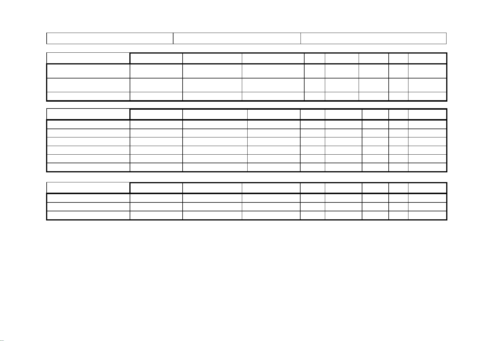
TECHNICAL DATA LIST
K230F 11596 + 11597
KRØLL CRANES A/S
HOIST
MANUFAC
TYPE
SERIAL NO.
kW
RPM
RATIO
QTY
P/N
E1509/5428379_02 001
E1509/5428379_02 002
4197677 01
4196220 01
SLEWING
MANUFAC
TYPE
SERIAL NO.
kW
RPM
RATIO
QTY
P/N
MOTOR without encoder
Siemens
1LA7113-4AA11-Z
11.5
2850
- 1 15.00050889
MOTOR with encoder
Siemens
1LA7113-4AA11-Z
11.5
2850
- 1 15.00050890
BRAKE
Krøll Cranes A/S
K-Brake 180V
- - - - 2
16.00045720
GEAR
Bonfiglioli
309L4HZ
SK 1500863X
- - 1:465
2
17.00057190
SLEWING RING
Rothe Erde
061.50.1390.203.49.1502
- - - 1
37.00037277
TROLLEY
MANUFAC
TYPE
SERIAL NO.
kW
RPM
RATIO
QTY
P/N
MOTOR WITH BRAKE
Siemens
1LP7113
6 - 1 15.00050891
GEAR
Bonfiglioli
A55
4194676 0X
-
1:40.303
1
17.00063214
12
MOTOR WITH BRAKE
GEAR
Siemens 1LP9207
Bonfiglioli A90
42.5 1750 - 1 15.00050916
- - 1:55.03 1 17.00063202
L:\Tor\Projekter\K230F\11596 11597\Manual\08 Equipment manuals\01 QA 37_1 Technical data list.doc Page 1of 1 FORM QA 37
Page 3
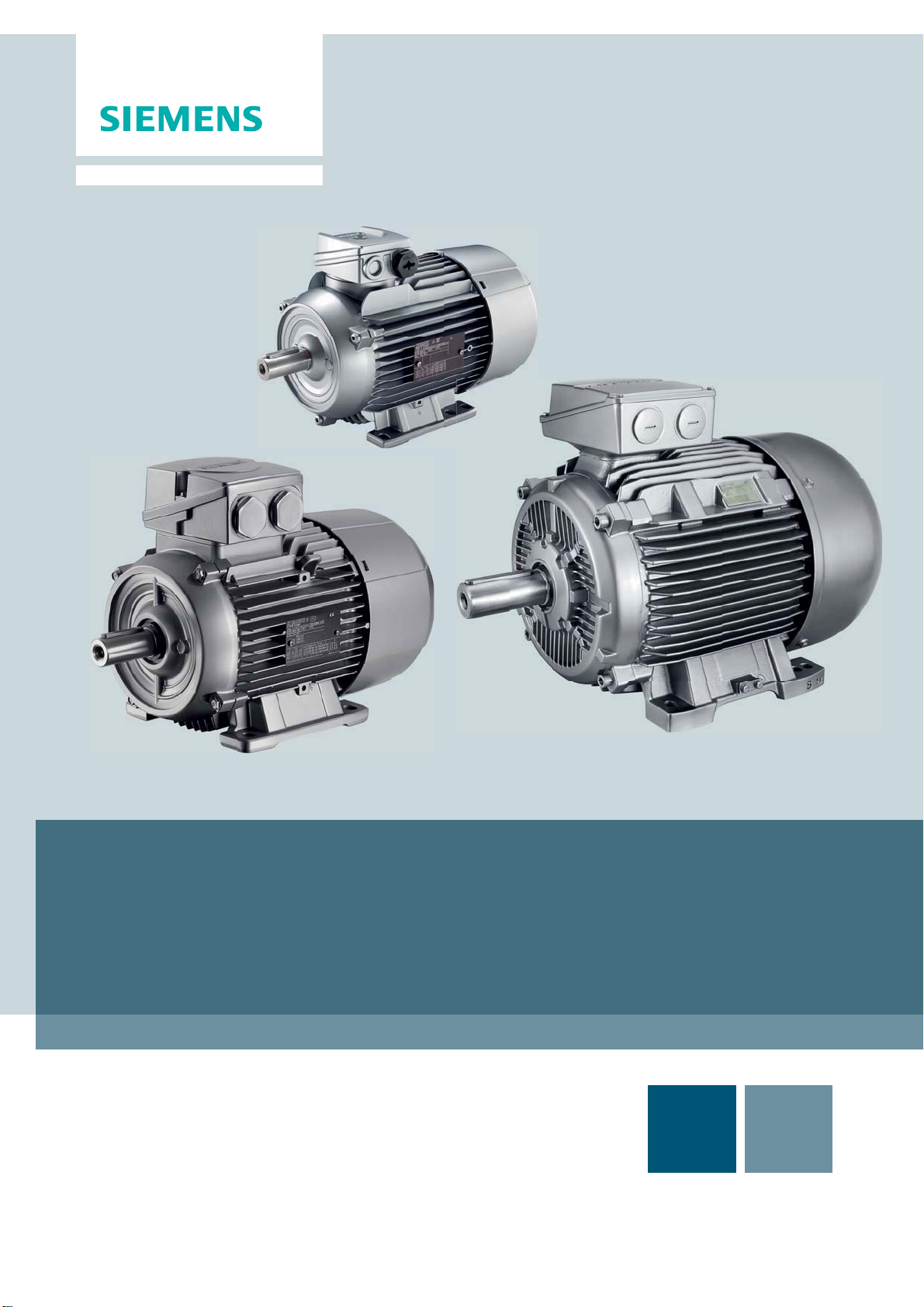
SIMOTICS Low-voltage motors
GP, SD, DP
1LA , 1LE, 1LF, 1LG, 1LP, 1PC, 1PF, 1PK, 1PP, 1PQ, 2KG
Compact Operating Instructions
02/2013Ausgabe
5 610 00000 02 001
© Siemens AG 2013
Answers for industry.
Page 4
SIMOTICS GP, SD, DP
Low-voltage motors
Compact Operating Instructions
1 Introduction
1.1 Information for the reader
Explanation of the icons
Note for 1LE1, 1MB1, 1PC1, 1PC3 machines
Note for 1LE1, 1PC1 and 1PC3 machines, frame sizes 80 and 90 with central
terminal box locking
2 Safety notes
2.1 Information for those responsible for the plant or system
This electric machine has been designed and built in accordance with the
specifications contained in Directive 2006/95/EC ("Low-Voltage Directive") and is
intended for use in industrial plants. Please observe the country-specific regulations
when using the electric machine outside the European Community.
Follow the local and industry-specific safety and setup regulations.
The persons responsible for the plant must ensure the following:
● Planning and configuration work and all work carried out on and with the machine
is only to be done by qualified personnel.
● The operating instructions must always be available for all work.
© Siemens AG 2010 - 2013. All rights reserved
34 56100000002001, 02/2013
Page 5

11BSafety notes
● The technical data as well as the specifications relating to the permissible
installation, connection, ambient and operating conditions are taken into account
at all times.
● The specific setup and safety regulations as well as regulations on the use of
personal protective equipment are observed.
Note
Use the services and support provided by the appropriate Service Center for
planning, installation, commissioning, and servicing work.
In the individual chapters of this document, you will find safety instructions that must
be obeyed absolutely, for your own safety, to protect other people and to avoid
damage to property.
Observe the following safety instructions for all activities on and with the machine.
2.2 The five safety rules:
For your personal safety and to prevent material damage when carrying out any
work, always observe the safety instructions and the following five safety rules,
according to EN 50110-1 "Working in a voltage-free state". Apply the five safety rules
in the sequence stated before starting work.
Five safety rules
1. Disconnect the system.
Disconnect the auxiliary circuits, for example anti-condensation heating
2. Prevent reconnection.
3. Make sure that the equipment is at zero voltage
4. Ground and short-circuit
5. Cover or isolate nearby components that are still live.
To energize the system, apply the measures in reverse order.
2.3 Qualified personnel
All work at the machine must be carried out by qualified personnel only. For the
purpose of this documentation, qualified personnel is taken to mean people who fulfill
the following requirements:
● Through appropriate training and experience, they are able to recognize and
avoid risks and potential dangers in their particular field of activity.
● They have been instructed to carry out work on the machine by the appropriate
person responsible.
Standard motors
56100000002001, 02/2013
35
Page 6
11BSafety notes
2.4 The safe use of electrical machines
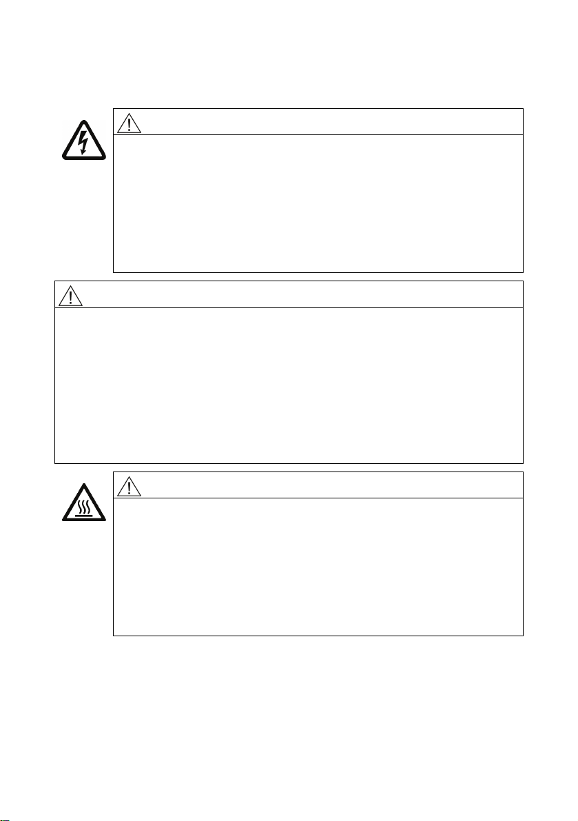
WARNING
Live parts
Electrical machines contain live parts.
Fatal or severe injuries and substantial material damage can occur if the
required covers are removed or if the machines are not handled,
operated, or maintained properly.
● Only remove covers in compliance with the applicable regulations.
● Operate the machines properly.
Rotating parts
Electrical machines contain dangerous rotating parts.
Fatal or severe injuries and substantial material damage can occur if the required
covers are removed or if the machines are not handled, operated, or maintained
properly.
● Only remove covers in compliance with the applicable regulations.
● Operate the machines properly.
● Perform regular maintenance on the machine.
● Secure free-standing shaft extensions.
● Perform regular maintenance on the machine.
WARNING
WARNING
Hot surfaces
Electrical machines have hot surfaces.
Fatal or severe injuries and substantial material damage can occur if the
required covers are removed or if the machines are not handled,
operated, or maintained properly.
● Allow the machine to cool down before starting any work on it.
● Only remove covers in compliance with the applicable regulations.
● Operate the machines properly.
Standard motors
36 56100000002001, 02/2013
Page 7
3 Description
3.1 Language versions on the Internet
Language versions can be found on the Internet
Internet page: http://www.siemens.com/motors
If you require additional language versions, please contact the Siemens Service
Center.
Intended use of the machines
These machines are intended for industrial installations. They comply with the
harmonized standards of the series EN / IEC 60034 (VDE 0530). Their use in
hazardous areas is forbidden unless the marking on the rating plate expressly
permits this operation. If other/more wide-ranging demands (e.g. protection so that
they cannot be touched by children) are made in special cases – i.e. use in nonindustrial installations – these conditions must have been complied with in the plant
or system itself when the motors are installed.
Note
Machine directive
Low-voltage motors are components designed for installation in machines in
accordance with the current Machinery Directive. The system may not be
commissioned until confirmation has been given that the final product is in
conformance with this directive (observe EN 60204-1 !).
Forced ventilation (optional): Cooling IC 416 in accordance with EN / IEC 60034-6
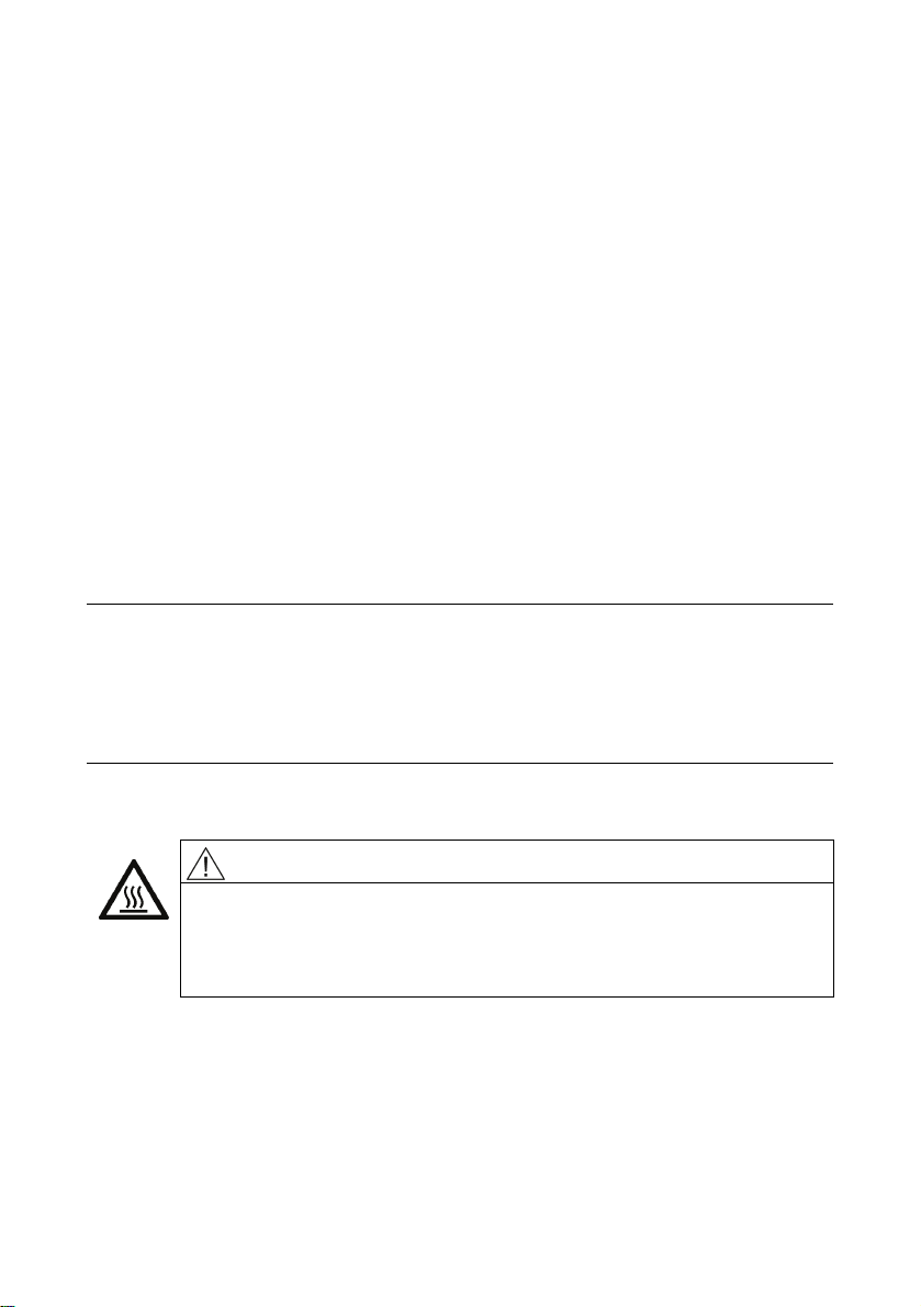
WARNING
Hot surfaces
Operating the machine without external fan results in overheating. This
may result in personal injury and material damage.
Never commission the machine without an external fan.
Cooling that does not depend on the speed is achieved by means of a separately
driven fan wheel (forced ventilation). Forced ventilation does not depend on the
operating state of the machine.
The fan wheel for the external flow of cooling air is powered by an independent
module and is enclosed by the fan cover.
Standard motors
56100000002001, 02/2013
37
Page 8
12BDescription
3.2 Degree of protection
The degree of protection the machines feature is stated on the rating plate. They can
be installed in dusty or humid environments.
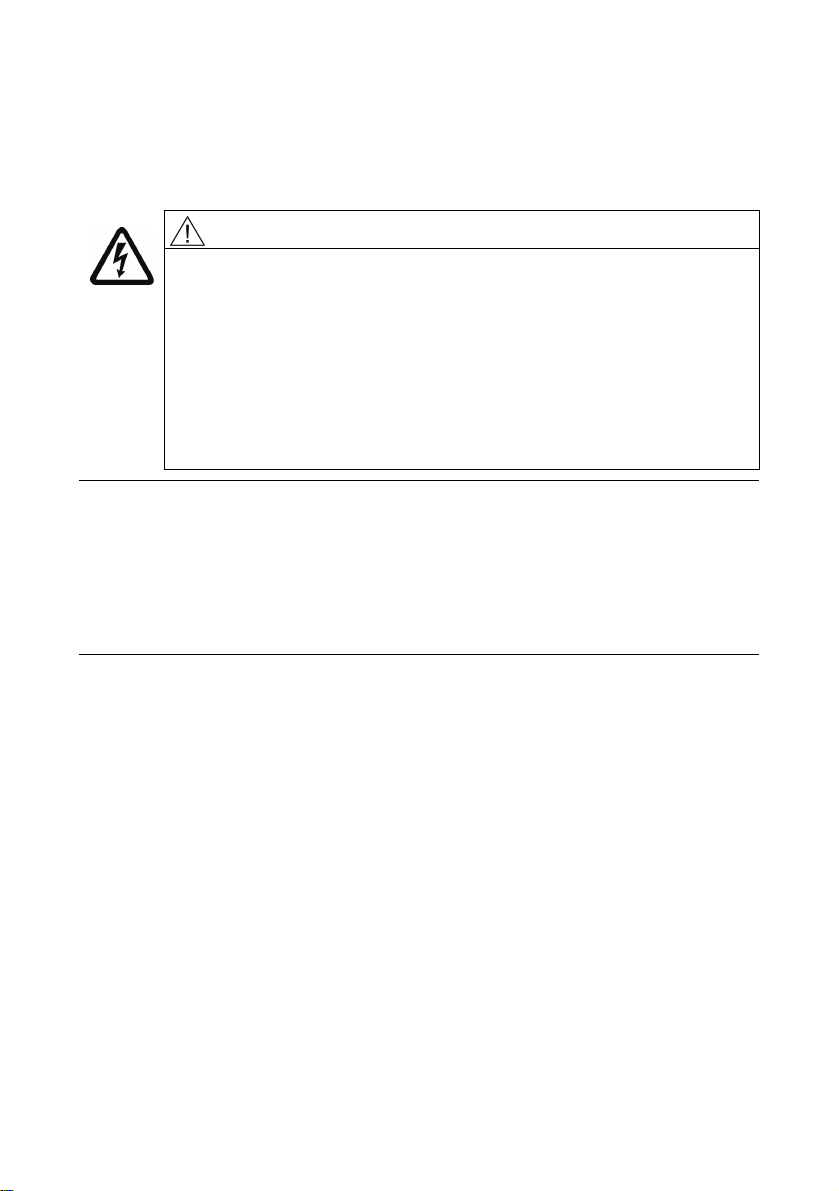
WARNING
Dangerous voltage
Condensation drain holes (optional)
Inserting objects into the condensation drain holes can damage the
winding and can result in death, serious injury and damage to property!
Note the following to maintain the degree of protection:
● Switch off the machine so that it is in a no-voltage condition, before
you open the condensation drain holes.
● Close the condensation drain holes (e.g. using T-plugs) before
Note
Storage
If the machines are used or stored outdoors, we recommend keeping them under a
shelter or an additional cover.
● Avoid exposing them to direct, intense solar radiation, rain, snow, ice, or dust for
extended periods.
● If necessary, please consult us or seek advice regarding technical issues.
commissioning the machine.
Environmental requirements
The machines are suitable for operation in tropical climates.
Guide value for the standard version 60 % relative humidity at an ambient
temperature of (T
) 40 °C.
amb
Ambient temperature: -20 °C to +40 °C
Installation altitude: ≤ 1000 m
Air with normal oxygen content, usually 21 % (V/V)
If the environmental requirements are different from the details listed here, then the
values on the rating plate will apply.
Standard motors
38 56100000002001, 02/2013
Page 9
4 Preparing for use
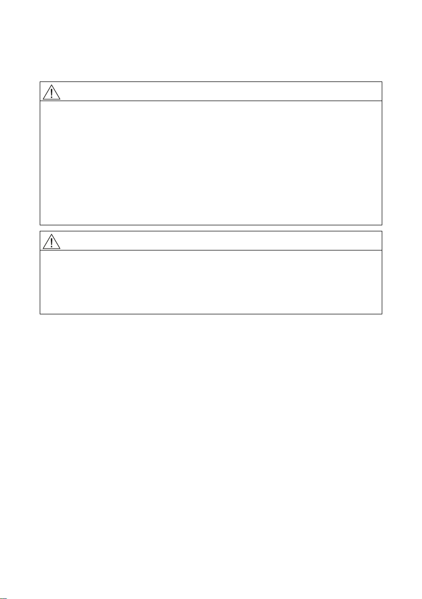
WARNING
Use lifting eyes
The machine must only be transported and lifted using the lifting eyes, in a position
that is appropriate for its type of construction. Otherwise, it could fall over or slip in
the lifting tackle.
This can result in death, serious injury, or material damage.
● Use all the lifting eyes on the machine.
● Any eyes that are screwed in must be tightly fastened.
● Eyebolts must be screwed in right up to their supporting surface.
● If necessary, use suitable, sufficiently-sized transport equipment such as lifting
straps (EN1492-1) and lashing straps (EN12195-2).
WARNING
Suspended transport
If several items of transport material are used for fastening, two straps must be able
to carry the whole load.
● Use additional, suitable means of support for transport and during installation.
● Secure the support equipment to prevent it from slipping.
Storage time
Turn the shafts 1x every year to avoid bearing brinelling. Prolonged storage periods
reduce the useful life of the bearing grease (aging).
Open bearings
● For open bearings e.g. 1Z, check the state of the bearing grease over 12 months.
● Replace the grease if it can be identified that the grease has lost oil content or
has become dirty (ingress of condensation leads to consistency changes of the
grease).
Closed bearings
● For closed bearings, replace the DE and NDE bearings after a storage time of 48
months
Standard motors
56100000002001, 02/2013
39
Page 10
5 Mounting, installation
5.1 Safety instructions
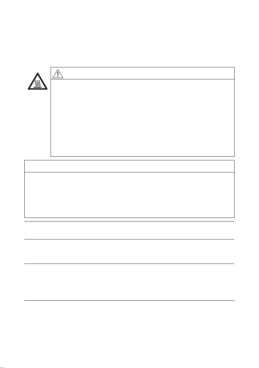
WARNING
Hot surfaces
Electrical machines have hot surfaces.
Fatal or severe injuries and substantial material damage can occur if the
required covers are removed or if the machines are not handled,
operated, or maintained properly.
● Allow the machine to cool down before starting any work on it.
● Only remove covers in compliance with the applicable regulations.
● Operate the machines properly.
It must be ensured that parts (cables etc.) do not come into contact with
the machine enclosure.
NOTICE
Before start-up, please check that
● the customer has set the correct direction of rotation of the machine - e.g. by
decoupling from the driven machine - by taking appropriate measures!
● there are no temperature-sensitive parts (cables etc.), which are in contact with
the machine enclosure.
● condensation drain holes are always located at the lowest point of the motor!
Note
Please note the technical data on the rating plates on the machine enclosure.
5.2 Electromagnetic compatibility
Note
If the torque levels are very unequal (e.g. when a reciprocating compressor is being
driven), a non-sinusoidal machine current will be induced whose harmonics can have
an impermissible effect on the supply system and cause impermissible interference
emissions as a result.
Standard motors
40 56100000002001, 02/2013
Page 11
14BMounting, installation
Note
Converter
● If operated with a frequency converter, the emitted interference varies in strength,
depending on the design of the converter (type, interference suppression
measures, manufacturer).
● Prevent the limit values stipulated by EN / IEC 61000-6-3 for the drive system
(consisting of the machine and converter) from being exceeded.
● You must observe the EMC information from the manufacturer of the converter.
● The most effective method of shielding is to conductively connect a shielded
machine supply cable to the metal terminal box of the machine (with a metal
screw connection) over a large surface area.
● On machines with integrated sensors (e.g. PTC thermistors), disturbance
voltages caused by the converter may occur on the sensor cable.
5.3 Balancing
CAUTION
Safety precautions
● The general touch protection measures for drive output elements must be
observed.
● Output elements may only be attached or withdrawn using the correct
equipment.
● The feather keys are only secured against falling out during shipping. If you
commission a machine without an output element, the feather keys must be
secured to prevent them from being thrown out.
The rotors are balanced dynamically. The balancing quality corresponds to vibration
severity grade "A" for the complete machine as standard. The optional vibration
severity grade "B" is indicated on the rating plate.
The declaration regarding the type of featherkey for balancing is generally marked on
the rating plate and optionally on the face of the shaft end.
Designation:
● As a standard measure, balancing is carried out dynamically with a half
featherkey (code "H") in accordance with ISO 8821.
● "F" means balancing with a whole featherkey (optional version).
● "N" means balancing without a featherkey (optional version).
Standard motors
56100000002001, 02/2013
41
Page 12
14BMounting, installation
Note
Measures conforming to ISO 10816 must be taken in order to compensate any offset
between electrical machines and driven machines.
The foundation must be designed according to DIN 4024.
5.4 Alignment and fastening
General
When aligning and fastening the machine, please bear the following in mind:
● The machine must be level.
● Feet and flanges must be fastened securely.
● Alignment must be precise in the case of direct coupling.
● Fastening surfaces must be clean
● Look out for any damage to paint; this must be rectified immediately and
correctly.
● Look out for traces of anti-corrosion protection agents; these must be removed
using mineral turpentine.
● Look out for installation-related resonances with the rotating frequency and
double line frequency; these must be prevented.
● Listen for unusual noises when turning the rotor manually.
● Check the direction of rotation with the machine decoupled.
● Avoid using rigid coupling measures.
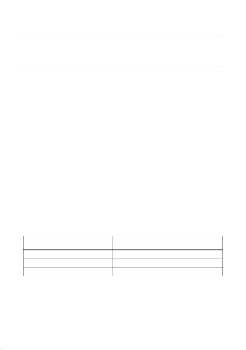
Flatness of the supporting surfaces for conventional motors
Frame size
(FS)
Flatness
mm
≤ 132 0.10
160 0.15
≥ 180 0.20
Standard motors
42 56100000002001, 02/2013
Page 13
6 Electrical connection
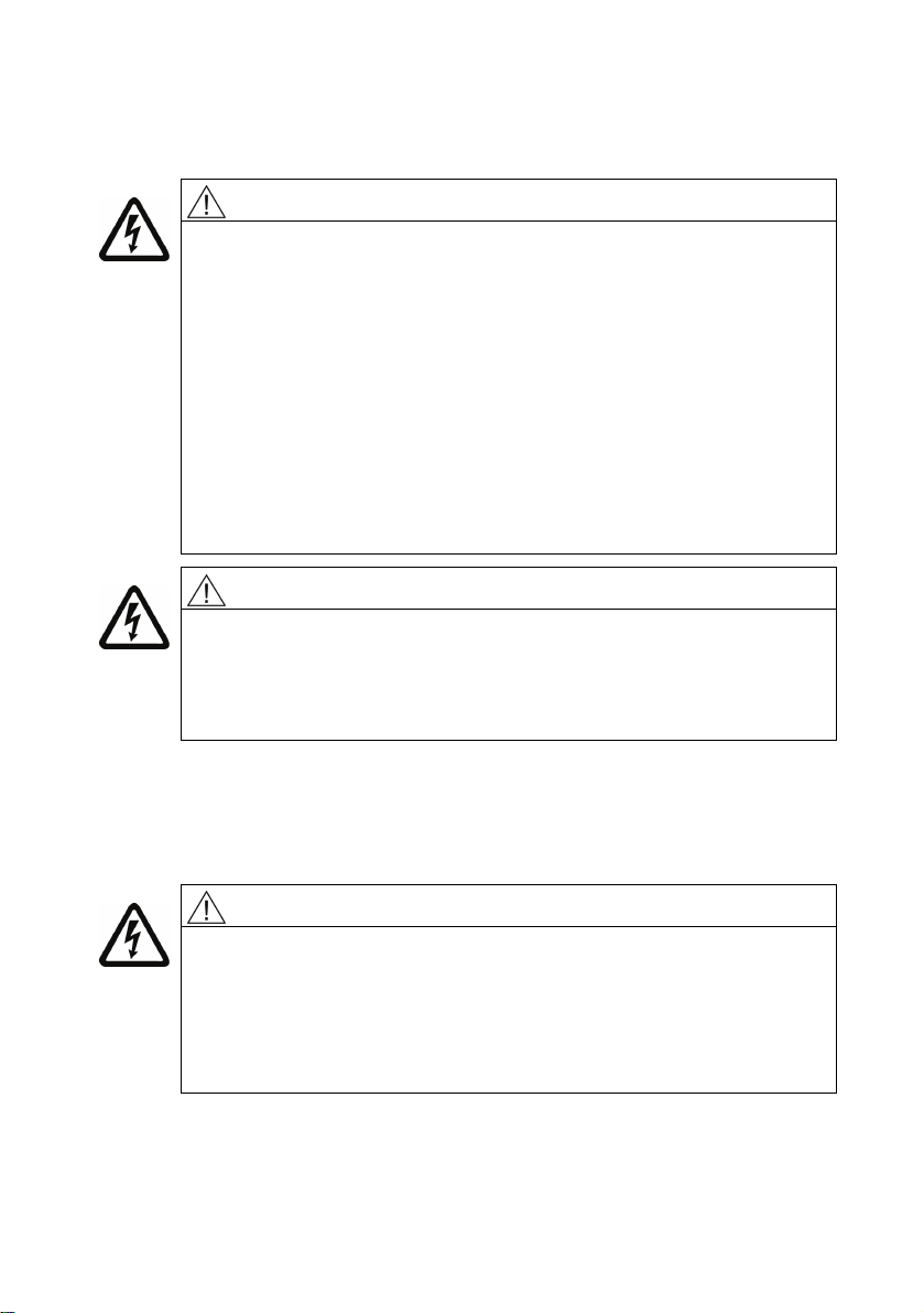
WARNING
Note the following safety information before connecting-up the machine:
● Only qualified and trained personnel should carry out work on the
machine while it is stationary.
● Disconnect the machine from the power supply and take measures to
prevent it being reconnected. This also applies to auxiliary circuits,
e.g. anti-condensation heating.
● Check that the machine really is in a no-voltage condition.
● Establish a safe protective conductor connection before starting any
work.
● If the incoming power supply system displays any deviations from the
rated values in terms of voltage, frequency, curve form or symmetry,
such deviations will increase the temperature and influence
electromagnetic compatibility.
WARNING
Line supply with non-grounded neutral point
Operating the machine on a line supply system with a non-grounded
neutral point is only permitted over short time intervals that occur rarely,
e.g. the time leading to a fault being eliminated (ground fault of a cable,
EN 60034-1).
Electrical connection
6.1 Terminal box
6.1.1 Instructions for terminal boxes
DANGER
Dangerous voltage
Electric machines contain hazardous voltages.
If the machine is not de-energized and brought into a no-voltage
condition, death or serious injury will occur.
When work is carried out on the machine with the terminal box open, it
must not be electrically connected!
Standard motors
56100000002001, 02/2013
43
Page 14
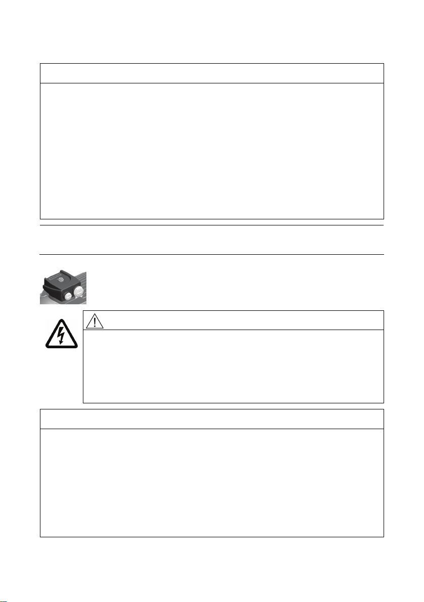
Electrical connection
NOTICE
Damage to property
Note the following information to avoid damage to the terminal box.
● Make sure that the components inside the terminal box e.g. terminal board and
cable connections) are not damaged!
● It must be ensured that there are no foreign bodies, dirt or moisture in the
terminal box.
Cable entries into the terminal box according to DIN 42925.
● Close any additional open cable entries with O-rings or suitable flat gaskets, the
terminal box itself must be sealed so that it is dust and water tight using the
original seal.
● Please observe the tightening torques for cable glands and other screws.
● When performing a test run, secure the feather keys without output elements.
Note
The terminal box must be sealed so that dust and water cannot enter.
WARNING
Dangerous voltage
Loosening the safety torx screw can result in death, serious injury or
material damage!
Do not loosen the safety torx screw with respect to the center terminal,
as this ensures a conductive connection between the grounding
conductor and frame!
NOTICE
Serious damage to the machine
Failure to observe these measures will result in serious damage to the machine!
● Do not rotate the terminal box unless the connection cables have not yet been
laid.
● If you release the safety torx screw to both sides of the outer connecting
terminals, this can destroy the machine!
● Remove the three large snap hooks on the terminal board before rotating the
the terminal box. Keep the snap hooks pressed while rotating the terminal box
and use a screwdriver to re-engage when finished.
Standard motors
44 56100000002001, 02/2013
Page 15
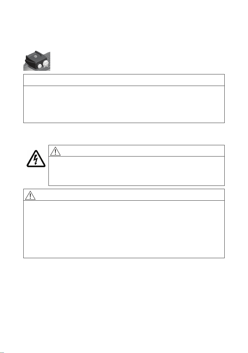
Electrical connection
6.1.2 Optional terminal board (star or delta circuit)
NOTICE
Arcing at the optional terminal board can destroy the machine
Failure to observe this information can result in destruction of the machine as a
result of arcing.
To change the operating mode, always press the jumper fully into the base of the
slot and use the red locking lever to ensure that it is engaged.
6.1.3 Protruding connection cables
WARNING
Short-circuit hazard
During disassembly and particularly when installing the cover plate,
make sure that the connection cables are not clamped between
enclosure parts and the cover plate.
CAUTION
It must be ensured that there are no foreign bodies, dirt, or moisture in the terminal
base of the machine enclosure.
● Use O-rings or suitable flat gaskets to seal entries in cover plates (DIN 42925)
and other open entries.
● Seal the terminal base of the machine enclosure using the original seal of the
cover plate to prevent dust and water from entering.
● Please observe the tightening torques for cable glands and other screws.
● When performing a test run, secure the feather keys without output elements.
Standard motors
56100000002001, 02/2013
45
Page 16
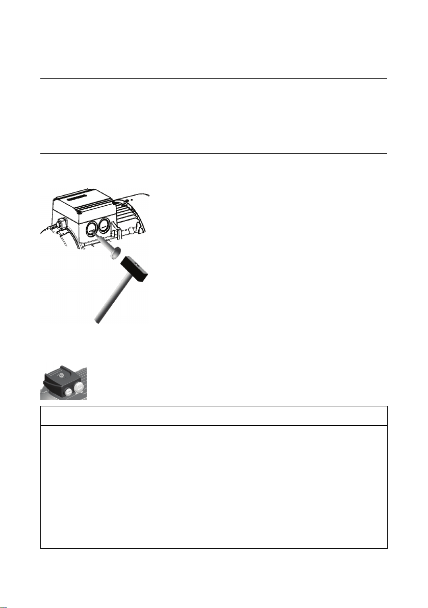
Electrical connection
6.1.4 Knockout openings
Note
Knockout openings
● Knockout openings in the terminal box must be knocked out using appropriate
methods.
● Take care not to damage the terminal box or its interior components (the terminal
board, cable connections, and so on).
6.1.5 Installation and routing
NOTICE
Damage to terminal board
Observe the following measures to prevent damage to the terminal board:
● Remove the screw-type connections (EN 50262) only when the terminal box is
● Tighten the screw-type connections to rated torque value only when the terminal
● Tighten the screw-type connections only finger tight when the terminal box is
● Make sure that the three large snap hooks are engaged when tightening the
Standard motors
46 56100000002001, 02/2013
closed.
box is closed.
open.
screw-type connections!
Page 17
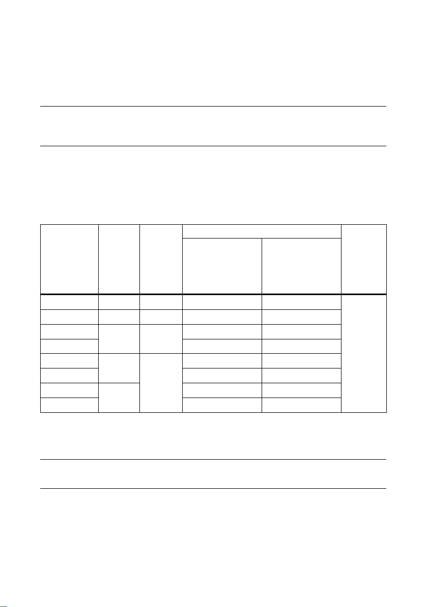
Electrical connection
6.2 Tightening torques
6.2.1 Cable glands
Note
Take care not to damage the cable jacket.
Tightening torques must be adapted to suit the type of cable jacket material in use.
You should refer to the table in order to find the correct tightening torque for any
metal and plastic cable glands that are to be mounted directly on the machine, as
well as for any other screw-type connections (such as adapters).
Table 6-1 Tightening torques for cable glands
Metal
± 10%
Nm
Plastic
± 10%
Nm
Clamping range in mm
Standard
-30 °C ... 100 °C
Ex
-30 °C ... 90 °C
Ex
-60 °C ... 105 °C
O ring
Cord ∅
mm
M 12 x 1,5 8 1,5 3,0 ... 7,0 M 16 x 1,5 10 2 4,5 ... 10,0 6,0 ... 10,0
M 20 x 1,5 7,0 ... 13,0 6,0 ... 12,0
M 25 x 1,5
M 32 x 1,5 11,0 ... 21,0 13,0 ... 20,0
M 40 x 1,5
M 50 x 1,5 26,0 ... 35,0 25,0 ... 31,0
M 63 x 1,5
12 4
18
20
9,0 ... 17,0 10,0 ... 16,0
6
19,0 ... 28,0 20,0 ... 26,0
2
34,0 ... 45,0 -
6.2.2 Terminal boxes, end shields, grounding conductors, sheet metal fan covers
Note
The specified tightening torques are applicable unless other values are indicated.
Standard motors
56100000002001, 02/2013
47
Page 18
Electrical connection
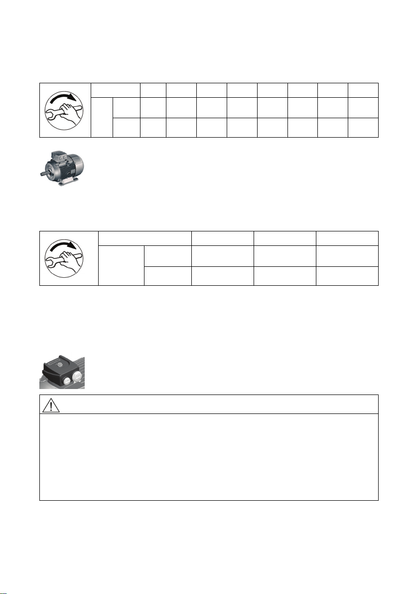
Table 6-2 Tightening torques for screws on the terminal box, end shields, screw-type
grounding conductor connections
Thread ∅ M 4 M 5 M 6 M 8 M 10 M 12 M 16 M20
min 2 3.5 6 16 28 46 110 225
Nm
max 3 5 9 24 42 70 165 340
Table 6-3 Tightening torques for self-tapping screws on the terminal box, end shields,
screw-type grounding conductor connections, sheet metal fan covers
Thread ∅ M 4 M 5 M 6
Nm
min 4 7.5 12.5
Max. 5 9.5 15.5
6.3 General information on conductor connection
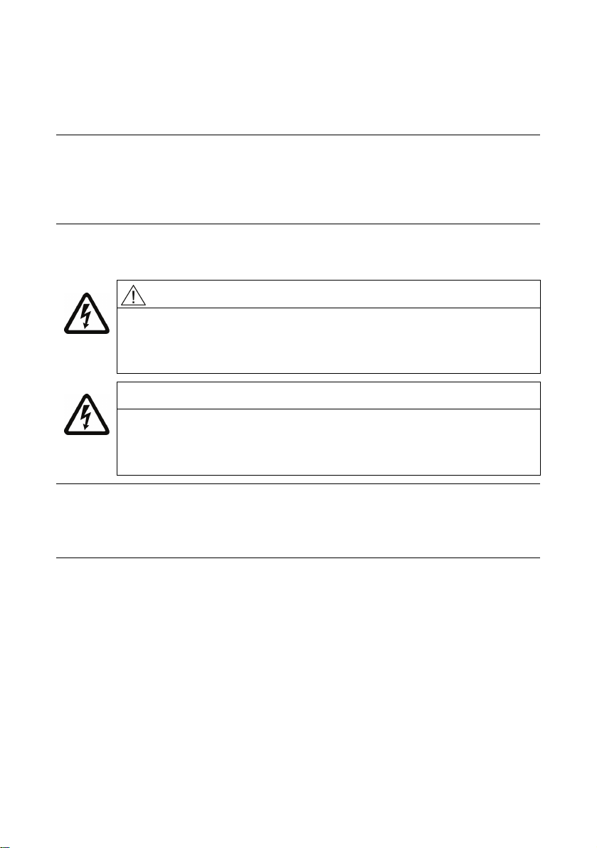
Cross-sections that can be connected depending on the size of the terminal (possibly
reduced due to size of cable entries)
Short-circuit hazard
Electric machines contain hazardous voltages.
If the appropriate precautions are not taken, death or serious physical injury can
occur.
● Do not lay connection cables over the central dome of the terminal board.
● Observe the opening direction and the mounting position of the cover washers
WARNING
on the terminal board.
Standard motors
48 56100000002001, 02/2013
Page 19
Electrical connection
6.4 General information on connecting the
grounding conductor
Note
The machine's grounding conductor cross-section must comply with EN / IEC 60034-
1 .
Please also observe installation regulations such as those specified in
EN / IEC 60204-1..
6.5 Connection to the converter
CAUTION
The standard insulation system is designed so that operation on the
converter is possible for supply voltages up to 500 V +10% in motorized
operation. Use a special insulation system or adopt special measures,
e.g. output filter, for higher voltages.
NOTICE
Machines must always be connected to frequency converters using
shielded machine supply cables. The most effective method of shielding
is to conductively connect the cable to the metal terminal box of the
machine (with metal screw connections) over a large surface area.
Note
EMC
Please observe the section containing instructions on ensuring electromagnetic
compatibility.
See the list of additional operating instructions: Further documents (Page 64)
Standard motors
56100000002001, 02/2013
49
Page 20

Electrical connection
6.6 Final checks
Before closing the terminal box/terminal base of the machine enclosure, check the
following:
● Establish the electrical connections in the terminal box in accordance with the
details in the sections above and tighten with the correct torque.
● The clearances between non-insulated parts have been maintained:
≥ 5.5 mm to 690 V, ≥ 8 mm to 1000 V.
● Avoid protruding wire ends!
● In order not to damage the cable insulation, freely arrange the connecting cables.
● Connect the machine corresponding to the specified direction of rotation.
● Keep the inside of the terminal box clean and free from trimmed-off ends of wire.
● Ensure that all seals and sealing surfaces are undamaged and clean.
● Correctly and professionally close unused openings in the terminal boxes.
● The pressure relief device is undamaged (depending on the type of terminal box,
this involves either cast-in slots or an overpressure diaphragm). Only repair
damage after prior consultation with the person responsible for the safety of the
equipment and use only original parts.
Standard motors
50 56100000002001, 02/2013
Page 21
7 Commissioning
7.1 Insulation resistance
WARNING
Working on electrical power installations
Only appropriately trained personnel may carry out this work.
Before starting commissioning, install all covers that are designed to
prevent active or rotating parts from being touched, or which are
necessary to ensure correct air guidance and thus effective cooling.
WARNING
Hazardous voltage at the terminals
Dangerous voltages are sometimes present on the terminals during and
immediately after measurement of the winding insulation resistance.
Contact with these can result in death, serious injury or material damage.
If any power cables are connected, check to make sure line supply
voltage cannot be connected. Once you have measured the insulation
resistance, discharge the winding by connecting to the ground potential.
Checking the insulation resistance
NOTICE
The insulation resistance needs to be checked prior to start-up and again after any
extended periods of storage or periods during which the equipment is not in
operation. Before you begin measuring the insulation resistance, please read the
operating manual for the insulation resistance meter you are going to use.
Disconnect any main-circuit cables that are connected to the terminals before
measuring the insulation resistance.
Note
If the critical insulation resistance is less than or equal to this value, the windings
must be dried or, if the fan is removed, cleaned thoroughly and dried.
Please note that the insulation resistance of dried, clean windings is lower than that
of warm windings. The insulation resistance can only be properly assessed after
conversion to the reference temperature of 25 °C.
Standard motors
56100000002001, 02/2013
51
Page 22
16BCommissioning
Note
If the measured value is close to the critical value, you must check the insulation
resistance at suitably frequent intervals.
Measuring the insulation resistance
1. Before you begin measuring the insulation resistance, please read the operating
manual for the insulation resistance meter you are going to use.
2. Disconnect any main circuit cables from the terminals before measuring the
insulation resistance.
3. Where possible, measure the insulation resistance of the winding with respect to
the motor enclosure when the winding temperature is between 20 ... 30 °C.
Different insulation resistance values apply for other temperatures.
4. When measuring, wait until the final resistance value is reached. This is reached
after approximately one minute. Then read off the insulation resistance.
Limit values of the stator winding insulation resistance
The following table indicates the measuring circuit voltage and the limit values for the
minimum insulation resistance and the critical insulation resistance of the stator
winding.
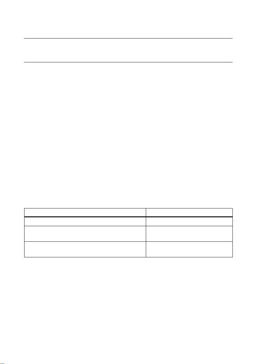
Table 7-1 Insulation resistance of the stator unwinding at 25 °C
Rated voltage U
rated
< 2 kV
Measuring circuit voltage 500 V
Minimum insulation resistance for new, cleaned
10 MΩ
or repaired windings
Critical specific insulation resistance after a
0,5 MΩ / kV
long operating time
Note the following:
● If the measurements are performed at winding temperatures ≠ 25 °C, convert the
measured value to the reference temperature of 25 °C in order to be able to
compare the values with the table above.
– The insulation resistance halves every time the temperature rises by 10 K.
– The resistance doubles every time the temperature falls by 10 K.
● Dry, new windings have a typical insulation resistance of more than
100 ... 2000 MΩ depending on the winding size, design and rated voltage. An
Standard motors
52 56100000002001, 02/2013
Page 23

16BCommissioning
insulation resistance value close to the minimum value could be due to moisture
and/or dirt accumulation.
● During operation, the insulation resistance of the windings can fall to the critical
insulation resistance due to ambient and operational influences. The critical
insulation resistance value for a winding temperature of 25 °C can be calculated
by multiplying the rated voltage (kV) by the specific critical resistance value
(0,5 MΩ / kV).
Example:
Critical resistance for rated voltage U
690 V x 0,5 MΩ / kV = 0,345 MΩ
Note
= 690 V:
N
Critical insulation resistance reached or fallen below
If the critical insulation resistance is reached or fallen below, this can result in
damage to the insulation or voltage flashovers.
● Contact your Siemens Service Center.
● If the measured value is close to the critical value, you must check the
insulation resistance at suitably frequent intervals.
Measures before commissioning
Once the system has been correctly installed, you should check the following prior to
commissioning:
● The machine has been assembled and aligned correctly.
● The machine has been connected so that it rotates in the direction specified.
● The operating conditions match the data specified on the rating plate.
● The bearings have been lubricated as appropriate for the version used. Rollingcontact bearing machines which have been in storage for more than 24 months
have been relubricated.
● Any supplementary machine monitoring equipment has been connected correctly
and is functioning as it should.
● For versions with bearing thermometers, the bearing temperatures must be
checked during the machine's first period of operation. The warning and
shutdown values are set on the monitoring device.
● Appropriately configured control and speed monitoring functions ensure that the
machine cannot exceed the permissible speeds specified on the rating plate.
Standard motors
56100000002001, 02/2013
53
Page 24

16BCommissioning
● The output elements have the correct settings for their type (e.g. alignment and
balancing of couplings, belt forces in the case of a belt drive, tooth forces and
tooth face clearance in the case of toothed-wheel power output, radial and axial
clearance in the case of coupled shafts).
● The minimum insulation resistance and minimum clearance values have been
adhered to.
● The grounding and equipotential bonding connections have been established
correctly.
● All fixing screws, connection elements, and electrical connections have been
tightened to the specified torques.
● Lifting eyes that were screwed in have been removed following installation or
secured to prevent them becoming loose.
● The rotor can turn without coming into contact with the stator.
● All touch protection measures for both moving and live parts have been
implemented.
● In cases where the shaft extension is not being used and is, therefore, exposed, it
has been covered and the feather key has been secured to prevent it from being
thrown out.
● If being used, the external fan is ready for operation and connected so that it
rotates in the direction specified.
● The flow of cooling air is not obstructed.
● If a brake is being used, it is functioning correctly.
● The specified mechanical limit speed n
is adhered to.
max
If the design of the machine requires the converter to be assigned in a particular way,
the relevant information will be provided on the rating plate or an additional label.
Note
It may be necessary to perform additional checks and tests in accordance with the
specific situation on site.
Standard motors
54 56100000002001, 02/2013
Page 25
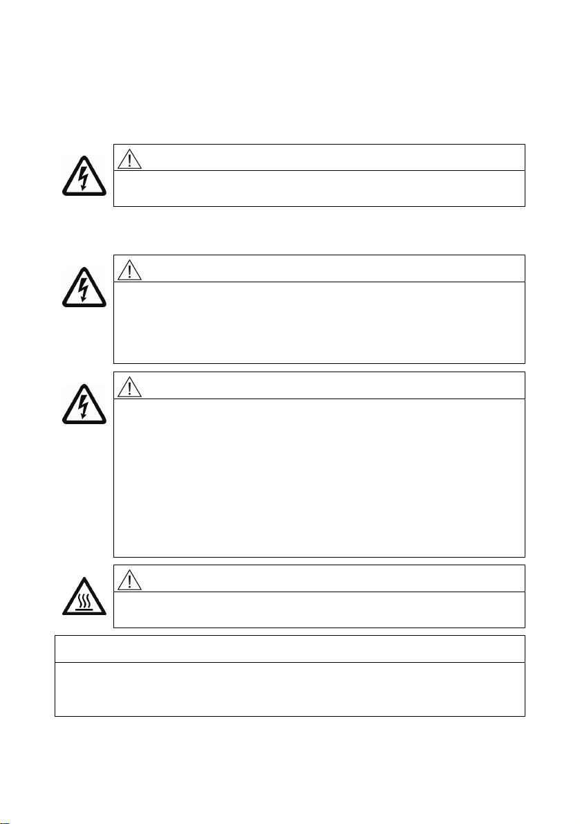
8 Operation
Switching on the machine with anti-condensation heating (optional)
CAUTION
Before switching on, always make sure that the (optional) anticondensation heating is switched off.
Machine operation
WARNING
Line supply with non-grounded neutral point
Operating the machine on a line supply system with a non-grounded
neutral point is only permitted over short time intervals that occur rarely,
e.g. the time leading to a fault being eliminated (ground fault of a cable,
EN / IEC 60034-1).
WARNING
Do not remove covers when the motor is running
Rotating or live parts are dangerous. Death, serious injury, or material
damage can result if the required covers are removed.
● De-energize the machine and bring it into a no voltage condition
before removing any covers.
● Ensure that any covers, which are designed to prevent active or
rotating parts from being touched, which are necessary to ensure
correct air guidance and thus effective cooling, or which guarantee
the degree of protection of the machine, remain closed during
NOTICE
Minimum load for cylindrical roller bearings
Be sure to comply with the minimum radial load of 30% of the cylindrical roller
bearings in accordance with catalog data.
operation.
CAUTION
The surfaces of the machines can reach high temperatures, which can
lead to burns if touched.
Standard motors
56100000002001, 02/2013
55
Page 26
17BOperation
WARNING
Faults during operation
Deviations from conditions during normal operation, such as an increase in power
consumption, temperatures or vibrations, unusual noises or odors, tripping of
monitoring devices, etc., indicate that the machine is not functioning properly. This
can cause faults which can result in eventual or immediate death, severe injury or
material damage.
● Immediately inform the maintenance personnel.
● If you are in doubt, immediately switch off the machine, being sure to observe
the system-specific safety conditions.
NOTICE
Risk of corrosion due to condensation
When changing machines and/or ambient temperatures, air humidity can condense
within the machines.
● If available, remove the screw plugs to drain the water depending on the
ambient and operating conditions.
● Reinsert them afterwards.
If the machine is equipped with drainage plugs, the water can drain away
automatically.
WARNING
Machines with textile fan covers
The machine fan is not completely protected against contact.
The customer must put suitable measures in place, e.g. housings or protective
grating, to prevent manual intervention.
8.1 Stoppages
Overview
If the machine remains out of service for an extended period of time (> 1 month), it
should be commissioned regularly (around once a month) or, at the very least, the
rotor should be turned. Please refer to the instructions in the section titled "Switching
on" before recommissioning the machine. If a rotor locking device has been fitted to
the machine, you must remove it before the rotor starts to turn.
Standard motors
56 56100000002001, 02/2013
Page 27

17BOperation
NOTICE
If the machine is to be out of service for a period in excess of 12 months, you must
take suitable anti-corrosion, mothballing, packaging, and drying measures.
Switching on the anti-condensation heater
If an anti-condensation heater is provided, switch it on during the machine
stoppages.
Taking the machine out of service
For details of measures that need to be implemented, please refer to Section
Preparing for use (Page 39).
L
ubricating before recommissioning
NOTICE
The machine must be relubricated during commissioning if it has been out of
service for more than 1 year, in order to ensure that the grease is distributed
throughout the bearings. The shaft must rotate for the grease to be distributed.
Please observe the information on the lubricant plate if carrying out relubrication
using relubrication equipment.
See also the section titled "Application planning - Bearing lifetime".
Standard motors
56100000002001, 02/2013
57
Page 28
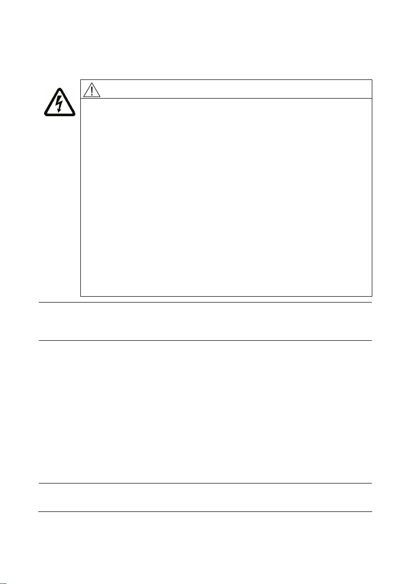
9 Maintenance
WARNING
Safety instructions
● Before starting work on the machines, make sure that the plant or
system has been disconnected in a manner that is compliant with the
appropriate specifications and regulations.
● In addition to the main currents, make sure that supplementary and
auxiliary circuits, particularly in heating devices, are also
disconnected.
● Certain parts of the machine may reach temperatures above 50 °C.
Physical contact with the machine could result in burn injuries! Check
the temperature of parts before touching them.
● When carrying out cleaning using compressed air, make sure that
appropriate methods of extracting fumes are in place and that
personal protective gear such as gloves, goggles, face masks,
or similar are worn.
● If you are using chemical cleaning agents, observe the instructions
and any warnings provided in the relevant safety data sheet.
Chemical agents must be compatible with the machine's
Note
Operation characteristics can vary widely. For this reason, only general maintenance
intervals can be specified here.
components, especially if these contain plastics.
9.1 Maintenance
9.1.1 Regreasing (optional)
General
As a standard feature, the machines have rolling-contact bearings which are
permanently lubricated with grease (UNIREX N3, made by ESSO). A regreasing
device is possible as an option. In this case, you can find information about
relubrication intervals, quantities and types of grease, and, if required, additional data
on the rating plate or lubricant plate.
Note
Do not mix different types of grease!
Standard motors
58 56100000002001, 02/2013
Page 29

18BMaintenance
Prolonged storage periods reduce the useful life of the bearing grease. Check the
condition of the grease if the equipment has been in storage for more than 12
months. If the grease is found to have lost oil content or to be contaminated, the
machine must be immediately relubricated before commissioning. For information on
permanently-greased bearings, please refer to the section titled Bearings (Page 60).
Note
Regreasing
1. Clean the grease nipples at the drive end and non-drive end.
2. Press in the type and quantity of grease specified (see rating/lubricant plate data).
● Please observe the information on the rating and lubricant plates.
● Regreasing should be carried out when the machine is running (max. 3600 rpm)!
The bearing temperature rises sharply at first, then drops to the normal value again
when the excess grease is displaced out of the bearing.
9.1.2 Cleaning
Cleaning the greasing channels and used grease chambers
The used grease collects outside each bearing in the used grease chamber of the
outer bearing cap. When replacing bearings, remove the used grease.
Note
You have to separate the active parts of the bearings to replace the grease that is in
the greasing channel.
Cleaning the cooling air passages
Regularly clean the cooling air passages through which the ambient air flows,
e.g. using dry compressed air.
Note
Never direct compressed air in the direction of the shaft outlet or machine openings.
In the case of machines with textile fan covers, regularly remove fluff balls, fabric
remnants, and similar types of contamination (particularly at the air passage opening
between the fan cover and cooling fins of the machine enclosure) to ensure that the
cooling air can flow without obstruction.
Standard motors
56100000002001, 02/2013
59
Page 30
18BMaintenance
Note
The frequency of the cleaning intervals depends on the local degree of
contamination.
WARNING
Particularly when carrying out cleaning using compressed air, make sure you use
suitable extraction equipment and wear personal protective gear (safety goggles,
respiratory filter, etc.).
9.2 Repair
9.2.1 Instructions for repair
Qualified personnel
Only appropriately qualified persons should be deployed to commission and operate
equipment. Qualified persons, as far as the safety instructions specified in this
manual are concerned, are those who have the necessary authorization to
commission, ground and identify/tag equipment, systems and circuits in accordance
with the relevant safety standards.
Instructions relevant to safety
WARNING
Before you begin working on the three-phase machine, in particular before you
open the covers of active parts, make sure that the three-phase machine or system
is properly isolated from the supply.
Note
If it is necessary to transport the machine, carefully observe the information provided
in Chapter Preparing for use !
9.2.2 Bearings
Take the bearing used up to frame size 90 only for special versions, and generally for
frame size 100 and higher from the rating plate.
Standard motors
60 56100000002001, 02/2013
Page 31
18BMaintenance
Bearing lifetime
Prolonged storage periods reduce the useful lifetime of the bearing grease. In the
case of permanently lubricated bearings, this leads to a shorter bearing lifetime.
Bearing or grease replacement is recommended after a storage time of 12 months,
for longer than four years, replace the bearings or grease.
Replacing bearings
Recommended interval after which bearings are to be replaced under normal
operating conditions:
Table 9-1 Bearing replacement intervals
Ambient temperature Principle of operation Bearing replacement
intervals
40° C Horizontal coupling
40 000 h
operation
40° C With axial and radial
20 000 h
forces
Note
Special operating conditions
Examples of factors that can reduce operating hours are vertical machine installation,
high vibrational and impact loads, frequent reversing, higher ambient temperature,
higher speeds, etc.
Note
● Do not reuse bearings that have been removed.
● Remove any existing contaminated old grease from the bearing shield!
● Replace old grease with new grease!
● Replace the shaft seals when the bearings are replaced.
● Lightly grease the contact surfaces of the sealing lips!
9.2.3 Dismantling
Note
Before commencing disassembly, you should mark how each of the fastening
elements has been assigned, as well as how internal connections are arranged, for
re-assembly purposes.
Standard motors
56100000002001, 02/2013
61
Page 32
18BMaintenance
Fan
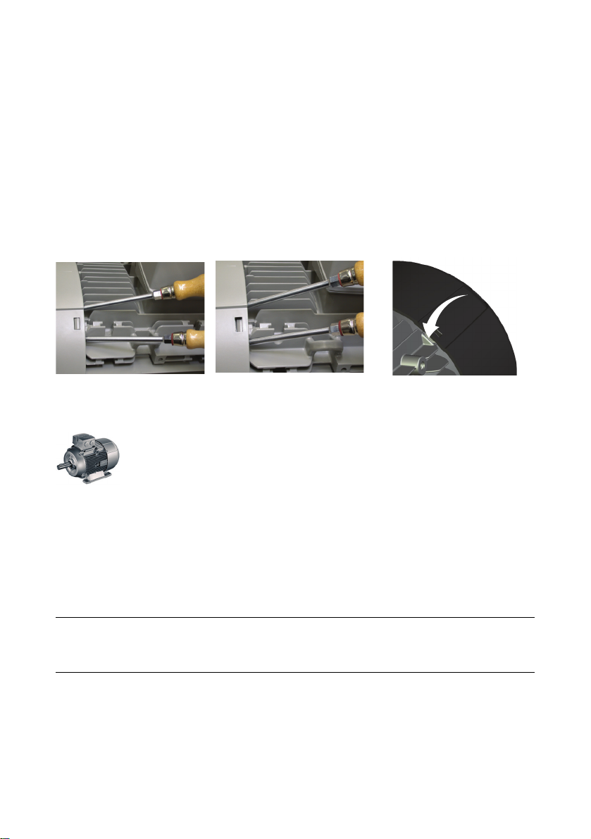
Take care not to damage the snapping mechanisms on fans that are equipped with
these. To ensure this, the fans should be heated to a temperature of approximately
50 °C around the area of the hub. If any damage is caused, request new parts.
Fan cover
● Carefully lever the snap openings on the cover out of the snap-in lugs one after
the other; do not apply the lever directly under the web (risk of breakage).
● Do not damage the snap mechanisms. If any damage is caused, request new
parts.
Canopy; incremental encoder under the canopy
Loosen the fixing screws on the external surface of the protective cover.
Under no circumstances should the spacing bolts or the mounting bracket be
disassembled or forcibly separated from each other or the cover. Forcibly removing
or separating can destroy the distance bolts, the connecting elements of the
mounting bracket or the fan cover.
9.2.4 Installation
Note
Avoid damaging the windings protruding out of the stator enclosure when fitting the
end shield.
Standard motors
62 56100000002001, 02/2013
Page 33
10 Spare parts
General
In addition to the exact part designation, please specify the machine type and the
serial number in all orders for spare parts and repair parts.
A Appendix
A.1 SIEMENS Service Center
Details regarding the design of this electrical machine and the permissible operating
conditions are described in these instructions.
Field service visits and spare parts
If you wish to request a field service call or order spare parts, please contact your
local Siemens sales office. This office will contact the responsible service center on
your behalf. You can find your local contact partner here.
Technical queries or additional information
If you have any technical queries or you require additional information, please
contact the Siemens Service Center.
Please have the following machine data ready:
● Machine type
● Serial number
You can find this data on the rating plate of the machine.
Service numbers
Table A-1 Siemens Service Center contact details
Time zone Telephone Fax Internet
Europe /
Africa
Americas +1 423
Asia /
Pacific
Standard motors
56100000002001, 02/2013
+49 911
895 7222
262 2522
+86 1064
757 575
+49 911
895 7223
+1 423
262 2200
+86 1064
747 474
http://www.siemens.com/automation/support-request
(http://www.siemens.de/automation/support-request
mailto:[email protected]
mailto:[email protected]
)
63
 Loading...