

Page 1
SIMOTION
Supplement to SIMODRIVE POSMO A Positioning Motor
Introduction
Fundamental safety
instructions
1
Function Manual
Description
Function blocks
Application example
Appendix
2
3
4
A
01/2015
Page 2

Legal information
Warning notice system
This manual contains notices you have to observe in order to ensure your personal safety, as well as to prevent
damage to property. The notices referring to your personal safety are highlighted in the manual by a safety alert
symbol, notices referring only to property damage have no safety alert symbol. These notices shown below are
graded according to the degree of danger.
DANGER
indicates that death or severe personal injury will result if proper precautions are not taken.
WARNING
indicates that death or severe personal injury may result if proper precautions are not taken.
CAUTION
indicates that minor personal injury can result if proper precautions are not taken.
NOTICE
indicates that property damage can result if proper precautions are not taken.
If more than one degree of danger is present, the warning notice representing the highest degree of danger will be
used. A notice warning of injury to persons with a safety alert symbol may also include a warning relating to property
damage.
Qualified Personnel
The product/system described in this documentation may be operated only by personnel qualified for the specific
task in accordance with the relevant documentation, in particular its warning notices and safety instructions. Qualified
personnel are those who, based on their training and experience, are capable of identifying risks and avoiding
potential hazards when working with these products/systems.
Proper use of Siemens products
Note the following:
WARNING
Siemens products may only be used for the applications described in the catalog and in the relevant technical
documentation. If products and components from other manufacturers are used, these must be recommended or
approved by Siemens. Proper transport, storage, installation, assembly, commissioning, operation and
maintenance are required to ensure that the products operate safely and without any problems. The permissible
ambient conditions must be complied with. The information in the relevant documentation must be observed.
Trademarks
All names identified by ® are registered trademarks of Siemens AG. The remaining trademarks in this publication
may be trademarks whose use by third parties for their own purposes could violate the rights of the owner.
Disclaimer of Liability
We have reviewed the contents of this publication to ensure consistency with the hardware and software described.
Since variance cannot be precluded entirely, we cannot guarantee full consistency. However, the information in
this publication is reviewed regularly and any necessary corrections are included in subsequent editions.
Siemens AG
Division Digital Factory
Postfach 48 48
90026 NÜRNBERG
GERMANY
Ⓟ 02/2015 Subject to change
Copyright © Siemens AG 2015.
All rights reserved
Page 3

Introduction
Contents of the function manual
This document is part of the SIMOTION Programming - References documentation package.
This documentation serves as a supplement to the documentation on SIMODRIVE POSMO
A in the
This documentation is included in the SIMOTION SCOUT scope of delivery as electronic
documentation!
This manual describes how you can use function blocks to control and assign parameters for
a POSMO A drive from a SIMOTION program.
This manual describes differences in handling that arise when controlling and assigning
parameters for a POSMO A drive from the SIMOTION system as compared to the SIMATIC
system.
Function block
The function blocks for communication between the SIMOTION system and the distributed
SIMODRIVE POSMO A positioning motor are part of the program library of the "SIMOTION
SCOUT" engineering system.
Distributed Positioning Motor on PROFIBUS DP
user manual.
SIMOTION Documentation
An overview of the SIMOTION documentation can be found in the SIMOTION Documentation
Overview document.
This documentation is included as electronic documentation in the scope of delivery of
SIMOTION SCOUT. It comprises ten documentation packages.
The following documentation packages are available for SIMOTION V4.4:
● SIMOTION Engineering System Handling
● SIMOTION System and Function Descriptions
● SIMOTION Service and Diagnostics
● SIMOTION IT
● SIMOTION Programming
● SIMOTION Programming - References
● SIMOTION C
● SIMOTION P
● SIMOTION D
● SIMOTION Supplementary Documentation
Supplement to SIMODRIVE POSMO A Positioning Motor
Function Manual, 01/2015 3
Page 4

Introduction
Hotline and Internet addresses
Additional information
Click the following link to find information on the following topics:
● Ordering documentation / overview of documentation
● Additional links to download documents
● Using documentation online (find and search manuals/information)
http://www.siemens.com/motioncontrol/docu
My Documentation Manager
Click the following link for information on how to compile documentation individually on the
basis of Siemens content and how to adapt it for the purpose of your own machine
documentation:
http://www.siemens.com/mdm
Training
FAQs
Technical support
Click the following link for information on SITRAIN - Siemens training courses for automation
products, systems and solutions:
http://www.siemens.com/sitrain
Frequently Asked Questions can be found in SIMOTION Utilities & Applications, which are
included in the scope of delivery of SIMOTION SCOUT, and in the Service&Support pages
in Product Support:
http://support.automation.siemens.com
Country-specific telephone numbers for technical support are provided on the Internet under
Contact:
http://www.siemens.com/automation/service&support
Supplement to SIMODRIVE POSMO A Positioning Motor
4 Function Manual, 01/2015
Page 5

Table of contents
Introduction...................................................................................................................................................3
1 Fundamental safety instructions...................................................................................................................7
1.1 General safety instructions.......................................................................................................7
1.2 Industrial security.....................................................................................................................7
2 Description....................................................................................................................................................9
2.1 General....................................................................................................................................9
2.2 Installation and startup...........................................................................................................11
2.3 Inserting a SIMODRIVE POSMO A positioning motor into a SIMOTION project...................12
2.4 Integrating the function blocks in the user project..................................................................13
2.5 Creating I/O Variables............................................................................................................14
3 Function blocks...........................................................................................................................................17
3.1 Overview of function blocks...................................................................................................17
3.2 Function block _POSMOA_control.........................................................................................17
3.3 Function block _POSMOA_nControl......................................................................................24
3.4 Function block _POSMOA_rwParameter...............................................................................29
3.5 Function block _POSMOA_rwAllParameter...........................................................................32
3.6 Calling function blocks...........................................................................................................38
4 Application example...................................................................................................................................41
4.1 General information on the application example....................................................................41
4.2 Operator control and monitoring of the application example in the detail view......................43
4.3 Variables used in application example...................................................................................47
A Appendix.....................................................................................................................................................51
A.1 SIMOTION and SIMATIC names...........................................................................................51
A.2 List of abbreviations...............................................................................................................55
Index...........................................................................................................................................................57
Supplement to SIMODRIVE POSMO A Positioning Motor
Function Manual, 01/2015 5
Page 6

Table of contents
Supplement to SIMODRIVE POSMO A Positioning Motor
6 Function Manual, 01/2015
Page 7
Fundamental safety instructions
1.1 General safety instructions
WARNING
Risk of death if the safety instructions and remaining risks are not carefully observed
If the safety instructions and residual risks are not observed in the associated hardware
documentation, accidents involving severe injuries or death can occur.
● Observe the safety instructions given in the hardware documentation.
● Consider the residual risks for the risk evaluation.
WARNING
Danger to life or malfunctions of the machine as a result of incorrect or changed
parameterization
As a result of incorrect or changed parameterization, machines can malfunction, which in turn
can lead to injuries or death.
● Protect the parameterization (parameter assignments) against unauthorized access.
● Respond to possible malfunctions by applying suitable measures (e.g. EMERGENCY
STOP or EMERGENCY OFF).
1
1.2 Industrial security
Note
Industrial security
Siemens provides products and solutions with industrial security functions that support the
secure operation of plants, solutions, machines, equipment and/or networks. They are
important components in a holistic industrial security concept. With this in mind, Siemens’
products and solutions undergo continuous development. Siemens recommends strongly that
you regularly check for product updates.
For the secure operation of Siemens products and solutions, it is necessary to take suitable
preventive action (e.g. cell protection concept) and integrate each component into a holistic,
state-of-the-art industrial security concept. Third-party products that may be in use should also
be considered. For more information about industrial security, visit http://www.siemens.com/
industrialsecurity.
To stay informed about product updates as they occur, sign up for a product-specific
newsletter. For more information, visit http://support.automation.siemens.com
Supplement to SIMODRIVE POSMO A Positioning Motor
Function Manual, 01/2015 7
Page 8
Fundamental safety instructions
1.2 Industrial security
WARNING
Danger as a result of unsafe operating states resulting from software manipulation
Software manipulation (e.g. by viruses, Trojan horses, malware, worms) can cause unsafe
operating states to develop in your installation which can lead to death, severe injuries and/
or material damage.
● Keep the software up to date.
Information and newsletters can be found at:
http://support.automation.siemens.com
● Incorporate the automation and drive components into a state-of-the-art, integrated
industrial security concept for the installation or machine.
For more detailed information, go to:
http://www.siemens.com/industrialsecurity
● Make sure that you include all installed products into the integrated industrial security
concept.
Supplement to SIMODRIVE POSMO A Positioning Motor
8 Function Manual, 01/2015
Page 9

Description
2.1 General
Overview
SIMODRIVE POSMO A is an intelligent distributed positioning drive on the PROFIBUS DP
field bus (DP standard slave).
The power unit and all of the motion control are located in the motor.
All of the signals and data for commissioning and operating the drive are transferred via the
PROFIBUS DP.
The operating energy is supplied by a 24 VDC connection (for a 75 W motor) or a 48 VDC
connection (for a 300 W motor).
The integrated positioning functionality is suitable for a variety of simple single-axis
applications, such as adjusting endstops and formats.
Note
Hardware and software requirements
The following requirements apply for the functionalities described in this manual:
● Hardware release POSMO A 75 W: As of O
● Software release POSMO A 75 W: As of V3.0
● Hardware release POSMO A 300 W: As of G
● Software release POSMO A 300 W: As of V3.0
2
POSMO A positioning motors with different hardware and software requirements can be
controlled with function blocks integrated in SIMOTION SCOUT V4.1. The functionality is
restricted by the hardware/software release of the POSMO A positioning motor used.
Requirement
The following software versions are required for the standard functions described in this
documentation:
● SIMOTION SCOUT V4.1 or higher
● SIMOTION Kernel V4.1 or higher
● SIMOTION technology packages V4.1 or higher
Communication
The PROFIBUS DP field bus allows rapid cyclical data exchange between the DP slave
(POSMO A) and the higher-level DP master (SIMOTION hardware platform, such as
SIMOTION C2xx).
Supplement to SIMODRIVE POSMO A Positioning Motor
Function Manual, 01/2015 9
Page 10

Description
2.1 General
Further information
Note
For more information, refer to the "Product brief" section of the
on PROFIBUS DP
This documentation is included in the SIMOTION SCOUT scope of delivery as electronic
documentation!
Installation and connection
For a description of how to install and connect a SIMODRIVE POSMO A and points you must
be aware of when doing so, refer to the "Installation and connection" section of the
Positioning Motor on PROFIBUS DP
On the SIMOTION device (hardware platform), connect SIMODRIVE POSMO A to one of the
PROFIBUS DP interfaces.
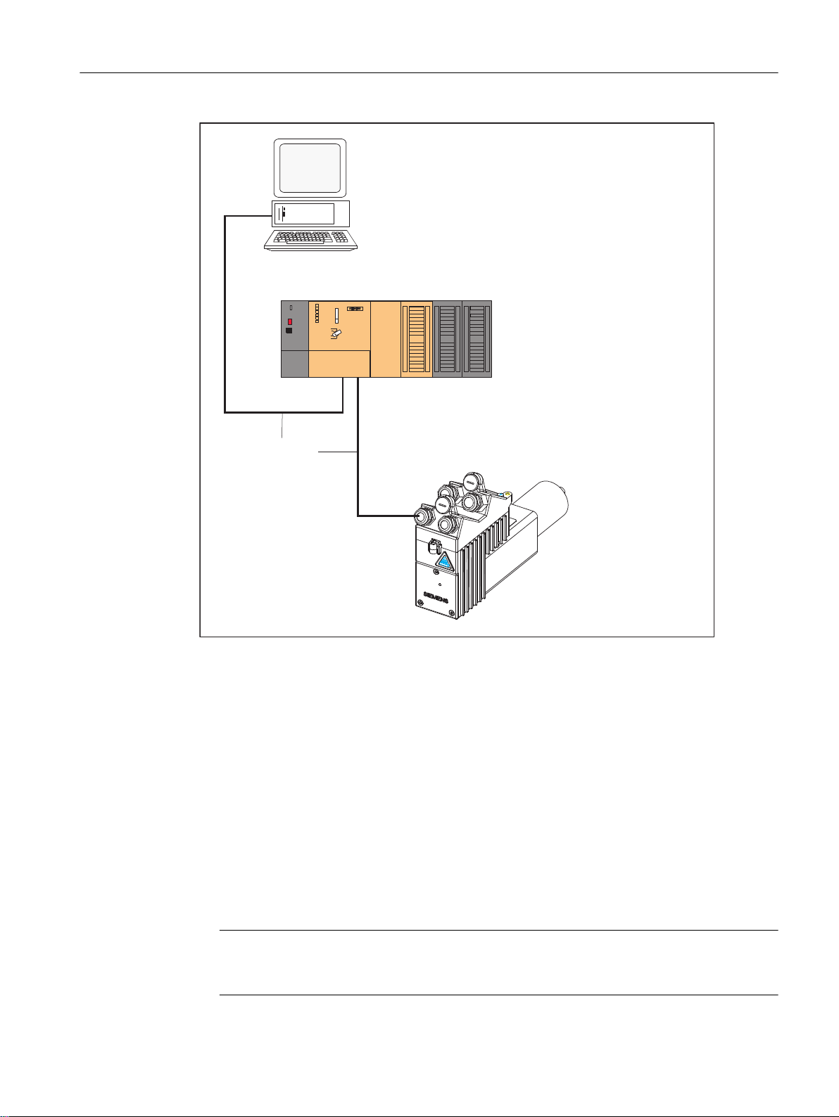
The following figure shows how to connect a SIMODRIVE POSMO A drive to a SIMOTION
hardware platform (such as SIMOTION C2xx).
Distributed Positioning Motor
user manual.
Distributed
user manual.
Supplement to SIMODRIVE POSMO A Positioning Motor
10 Function Manual, 01/2015
Page 11
6,027,21
+DUGZDUHSODWIRUP
VXFKDV&[[
352),%86'3
&[[
60V36
3RVLWLRQLQJ0RWRU
:
3*3&
Description
2.2 Installation and startup
2.2 Installation and startup
Overview
Supplement to SIMODRIVE POSMO A Positioning Motor
Function Manual, 01/2015 11
Figure 2-1 Connection of SIMODRIVE POSMO A to the SIMOTION C2xx hardware platform
You must perform the following steps to commission the SIMODRIVE POSMO A and control
it from the SIMOTION system:
1. Mount and wire the SIMODRIVE POSMO A positioning motor.
2. Set the PROFIBUS DP node address on the connection cover of the SIMODRIVE
POSMO A.
3. Switch on the terminating resistor at the first and last bus node.
Note
For steps 1 to 3, refer to
Motor on PROFIBUS DP
Section "Installation and Connection"
user manual.
of the
Distributed Positioning
Page 12

Description
2.3 Inserting a SIMODRIVE POSMO A positioning motor into a SIMOTION project
4. You can use any of the following to commission the SIMODRIVE POSMO A:
– C1 master "SIMODRIVE POSMO A PROFIBUS MASTER"
– Commissioning tool "SimoCom A"
Note
Refer to the
Distributed Positioning Motor on PROFIBUS DP
user manual,
Section
"Commissioning of DP Master".
– "Drive ES" tool. This tool includes "SimoCom A"
Note
Refer to the
5. Insert the SIMODRIVE POSMO A into the SIMOTION project (refer to Section Inserting a
SIMODRIVE POSMO A positioning motor into a SIMOTION project (Page 12)).
6. Control the SIMODRIVE POSMO A from the SIMOTION system using function blocks, see
Section Function blocks (Page 17).
Note
Refer to the
information on the following topics:
● Axis commissioning
● Communication via PROFIBUS DP
● Description of functions
● Error handling and diagnostics
● Assembly and service
Drive ES Basic
Distributed Positioning Motor on PROFIBUS DP
function description.
user manual for more
2.3 Inserting a SIMODRIVE POSMO A positioning motor into a
SIMOTION project
Requirement
The following requirements must be met:
1. You have created a project in SIMOTION SCOUT and have inserted a rack with a
SIMOTION hardware platform in the hardware configuration.
2. You have configured a PROFIBUS subnet.
Note
For information on creating a project and configuring a PROFIBUS subnet, refer to the
online help for SIMOTION SCOUT.
Supplement to SIMODRIVE POSMO A Positioning Motor
12 Function Manual, 01/2015
Page 13

Inserting SIMODRIVE POSMO A
To integrate the SIMODRIVE POSMO A into the PROFIBUS subnet of your project, proceed
as follows:
1. In SIMOTION SCOUT, open the User Projects dialog box with the Project > Open menu
command. In this dialog box, select your project and confirm your choice with OK.
2. Open HW Config (by double-clicking the SIMOTION device in the project navigator of
SIMOTION SCOUT).
3. In the HW Config window, open the hardware catalog with the View > Catalog menu
command.
4. In the hardware catalog, open the PROFIBUS DP folder and the SIMODRIVE subfolder
and select SIMODRIVE POSMO A.
5. Use a drag-and-drop operation to move the SIMODRIVE POSMO A onto the PROFIBUS
subnet of your project.
The Properties - PROFIBUS Interface SIMODRIVE POSMO A dialog box is displayed. In
this dialog box, you select the address you set in the connection cover of POSMO A (see
Section "Installation and Connection" of the Distributed Positioning Motor on PROFIBUS
DP
user manual) and confirm with OK.
The SIMODRIVE POSMO A positioning motor you have selected is inserted into the project.
Description
2.4 Integrating the function blocks in the user project
6. Input and output addresses of the POSMO A.
When you insert the POSMO A into your SIMOTION project, the input and output addresses
are assigned default values. You can see these values when you select the inserted
POSMO A. You can read the input and output addresses in the lower part of the HW
Config window.
You must create these addresses as I/O variables in the symbol browser before calling the
function blocks; see Section Creating I/O Variables (Page 14).
2.4 Integrating the function blocks in the user project
Creating the instance of the FBs in the user project
The function blocks are part of the program library of the SIMOTION SCOUT engineering
system. For working with the blocks, an instance has to be created in the user project for each
function block used and if using the _POSMOA_rwAllParameter function block, a variable of
type Struct_POSMOA_params.
Example:
VAR_GLOBAL
...
myPosmoAControl : _POSMOA_control; // FB for controlling of POSMO A
myPosmoArwParameter : _POSMOA_rwParameter; // FB for handling single parameter
myPosmoArwAllParameter : _POSMOA_rwAllParameter; // FB for handling parameterset
myAllParaPosmoA : Struct_POSMOA_params; // Variable for structure of all
// parameters POSMO A
Supplement to SIMODRIVE POSMO A Positioning Motor
Function Manual, 01/2015 13
Page 14

Description
2.5 Creating I/O Variables
...
END_VAR
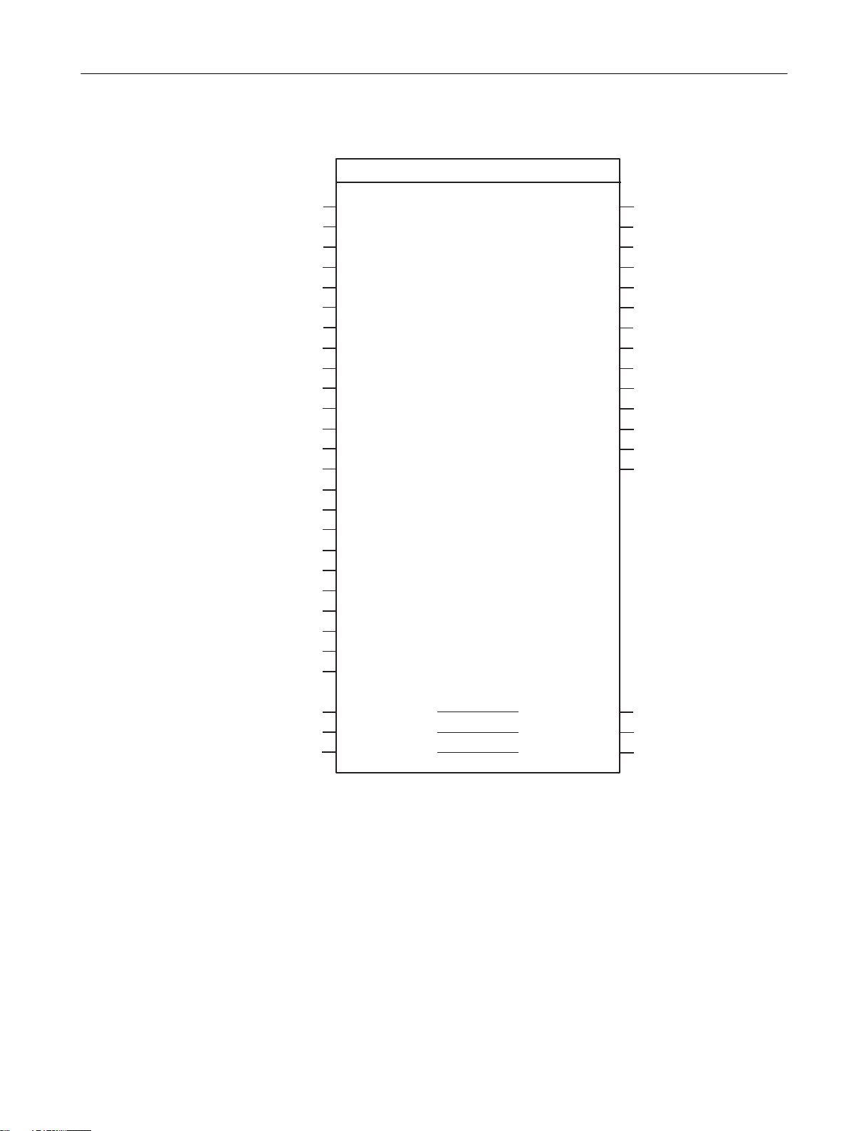
Call (LAD representation)
The LAD representation of the individual function blocks can be found in the respective function
block descriptions.
Example of an application
The application example is contained on the "SIMOTION Utilities & Applications" CD-ROM
and is available for various SIMOTION hardware platforms.
The "SIMOTION Utilities & Applications" CD-ROM is provided free of charge and part of the
SIMOTION SCOUT scope of delivery.
2.5 Creating I/O Variables
Overview
Communication between the SIMOTION hardware platform and the SIMODRIVE POSMO A
takes place through direct access to the I/O. I/O variables are used to address the direct read/
write access to the I/O.
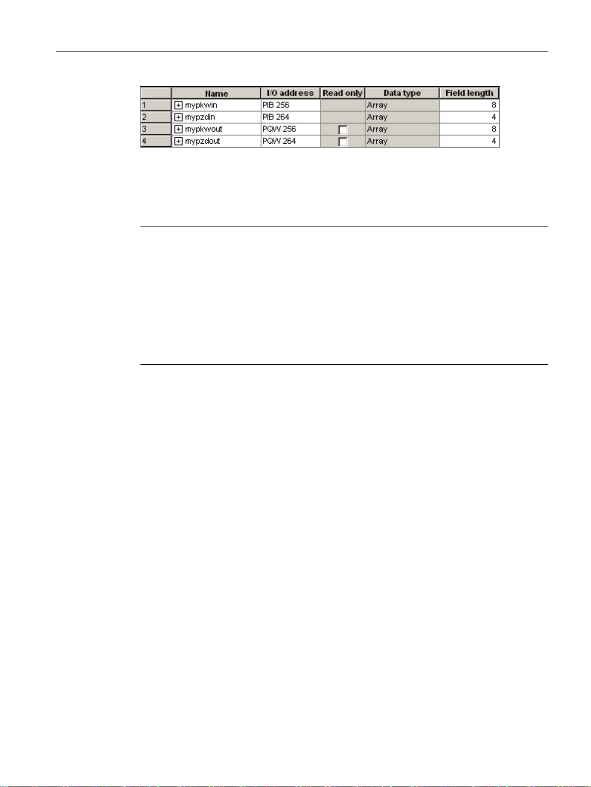
You can freely assign the names of I/O variables in SIMOTION SCOUT. You must define the
I/O variables as ARRAY [0..7] and [0..3] of BYTE. You assign the address settings in the
hardware configuration to these I/O variables.
The names of the I/O inputs must be transferred to the function blocks as call parameters. The
prepared data for the I/O outputs are provided by the function block as in/out parameters. The
in/out parameters must be be supplied with variables of type ARRAY [0..7] of BYTE and [0..3]
of BYTE. Once the block has been called, these variables must be assigned to the I/O variables
for the I/O outputs; see call example in Section Calling function blocks (Page 38).
Note
The variable for supplying the in/out parameters must not be created as a temporary variable
(VAR_TEMP or local variable of a function).
The following example shows how to assign the module addresses to the I/O variables in
SIMOTION SCOUT.
Supplement to SIMODRIVE POSMO A Positioning Motor
14 Function Manual, 01/2015
Page 15
Description
2.5 Creating I/O Variables
Figure 2-2 Address assignment in SIMOTION SCOUT
Each input and output address has a range of 8 bytes (which corresponds to the parameter
identifier value (PKW) range of POSMO A) and a range of 4 bytes (which corresponds to the
process data (PZD) range of POSMO A).
Note
For additional information, refer to:
●
SIMOTION SCOUT
online help
● Programming Manual of the corresponding programming language, e.g.:
–
SIMOTION ST, Structured Text
–
SIMOTION MCC, Motion Control Chart Programming Manual
–
SIMOTION LAD/FBD, Ladder Diagram and Function Block Diagram Programming
Programming Manual
Manual
These documents are shipped with SIMOTION SCOUT in electronic form!
Supplement to SIMODRIVE POSMO A Positioning Motor
Function Manual, 01/2015 15
Page 16

Description
2.5 Creating I/O Variables
Supplement to SIMODRIVE POSMO A Positioning Motor
16 Function Manual, 01/2015
Page 17

Function blocks
3.1 Overview of function blocks
This section contains a description of all of the function blocks (FBs) and the data structure
you need for communication between a SIMOTION hardware platform and the SIMODRIVE
POSMO A.
The function blocks form the software interface between the SIMOTION system and the
SIMODRIVE POSMO A positioning motor.
These function blocks make it easier to control and assign parameters for a SIMODRIVE
POSMO A positioning motor from the SIMOTION program.
For example, you can assign parameters for a POSMO A without being familiar with
PROFIBUS parameter formats and request specifiers.
The function blocks must be called repeatedly (in cycles) from the user program.
The following function blocks are available:
● Function block _POSMOA_control (Page 17)
● Function block _POSMOA_nControl (Page 24) (V4.1 and higher):
● Function block _POSMOA_rwParameter (Page 29)
3
● Function block _POSMOA_rwAllParameter (Page 32)
Note
For the complete control and communication of the SIMODRIVE POSMO A from the
SIMOTION program, an instance must be created for each _POSMOA_rwParameter and
_POSMOA_rwAllParameter function block and, depending on the parameterized operating
mode (speed or position control mode), an instance of the _POSMOA_control or
_POSMOA_nControl function block.
Note
If the SIMODRIVE POSMO A is disconnected and then reconnected to the power system, any
MDI traversing block data (see the table titled "Parameters of the _POSMOA_control function
block") that had been transferred previously must be transferred to the POSMO A again.
3.2 Function block _POSMOA_control
Task
You can control the connected SIMODRIVE POSMO A with the _POSMOA_control function
block.
Supplement to SIMODRIVE POSMO A Positioning Motor
Function Manual, 01/2015 17
Page 18

Function blocks
3.2 Function block _POSMOA_control
The functions are as follows:
● Initialize
Sets the drive in "ready to operate" mode.
Requirements:
– A drive fault has not been signaled (driveError = FALSE)
– Fault acknowledgement is not active (resetError = FALSE)
● Referencing
Sets the home position for the drive.
● Tippen
The drive travels at a controlled speed in a plus or minus direction.
● Program execution
Starts, stops, or aborts a single block addressed by blockNumber or a block within the
program.
● MDI
The drive travels at the assigned speed and acceleration to an assigned position.
The MDI parameters are transferred in block 3.
The MDI block can be started with blockNumber = 3 and start = TRUE.
● Fault acknowledgement
Acknowledges a fault in the drive.
Note
A fault must be acknowledged before the drive can move. This requires that parameter
enable = TRUE.
● Automatic single-block operation/automatic control
Checkback signals are as follows:
● Current traversing block
● Data Set Ready
● Warning and fault information
● Complete status (status word and checkback signal byte)
● Data transfer status
Supplement to SIMODRIVE POSMO A Positioning Motor
18 Function Manual, 01/2015
Page 19
Call (LAD representation)
DFWLYH
%22/
:25'
HUURU,'
%22/
HUURU
:25'
GULYH(UURU,G
%22/
GULYH(UURU
:25'
GULYH:DUQ,G
%22/
GULYH:DUQLQJ
%<7(
VWDWXV,QIRUPDWLRQ
%<7(
DFW%ORFN1XPEHU
%22/
$55$<>@RI%<7(
$55$<>@RI%<7(
EXV\
S]G2XW
SNZ2XW
$55$<>@RI%<7(
5($/PGL3RVLWLRQ
,17
PGL$FFHOHUDWLRQ
,17
PGL9HORFLW\
%22/PGL0RGH
%<7(
VHW6WDUW,QIRUPDWLRQ
%22/
UHVHW(UURU
%<7(EORFN1XPEHU
%22/
QR6WRS
%22/
QR6WRS,QWHUPHGLDWH
%22/
VWDUW
%22/
YHOR2YHUULGH
,17MRJ2YHUULGH
%22/MRJ
$55$<>@RI%<7(
$55$<>@RI%<7(
%22/
$55$<>@RI%<7(
HQDEOH
S]G,Q
S]G2XW
SNZ2XW
%22/
%22/
%22/
UHDG\
:25'
%22/
VWDWXV:RUGKRPLQJ
MRJ
B32602$BFRQWURO
EXV\
SNZ,Q
(1
(12
UHOHDVH%UDNH
%22/
%22/
VLQJOH%ORFN
HQDEOH5G,Q
H[W%ORFN&KDQJH
%22/
,17
%22/
UHT&RQWURO
%22/
GDWD5HDG\
GULYH:DUQ,QIR
:25'
/$'VSHFLILFSDUDPHWHUV
Function blocks
3.2 Function block _POSMOA_control
Supplement to SIMODRIVE POSMO A Positioning Motor
Function Manual, 01/2015 19
Page 20
Function blocks
3.2 Function block _POSMOA_control
Parameter description
Note
The SIMOTION identifiers have changed as of V4.0.
You can find a comparison of SIMOTION and SIMATIC names in the Appendix SIMOTION
and SIMATIC names (Page 51).
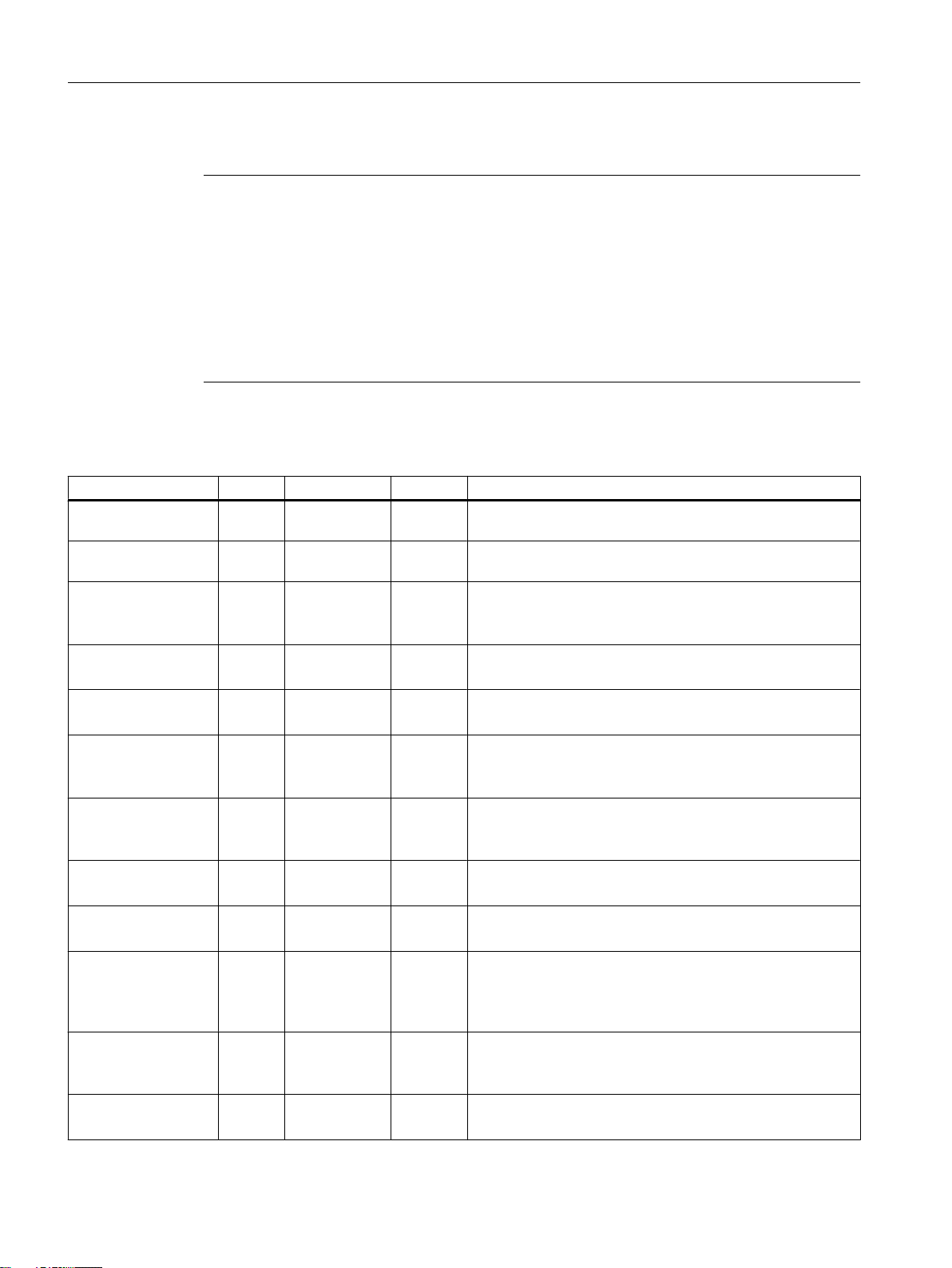
The busy parameter must not be overwritten by the user. It is supplied and checked by the
function block, and must be supplied with a global variable created by the user only when the
respective function block is called. This parameter coordinates the individual function blocks
for the POSMO A. This ensures that no more than one function block can access a POSMO A
at the same time.
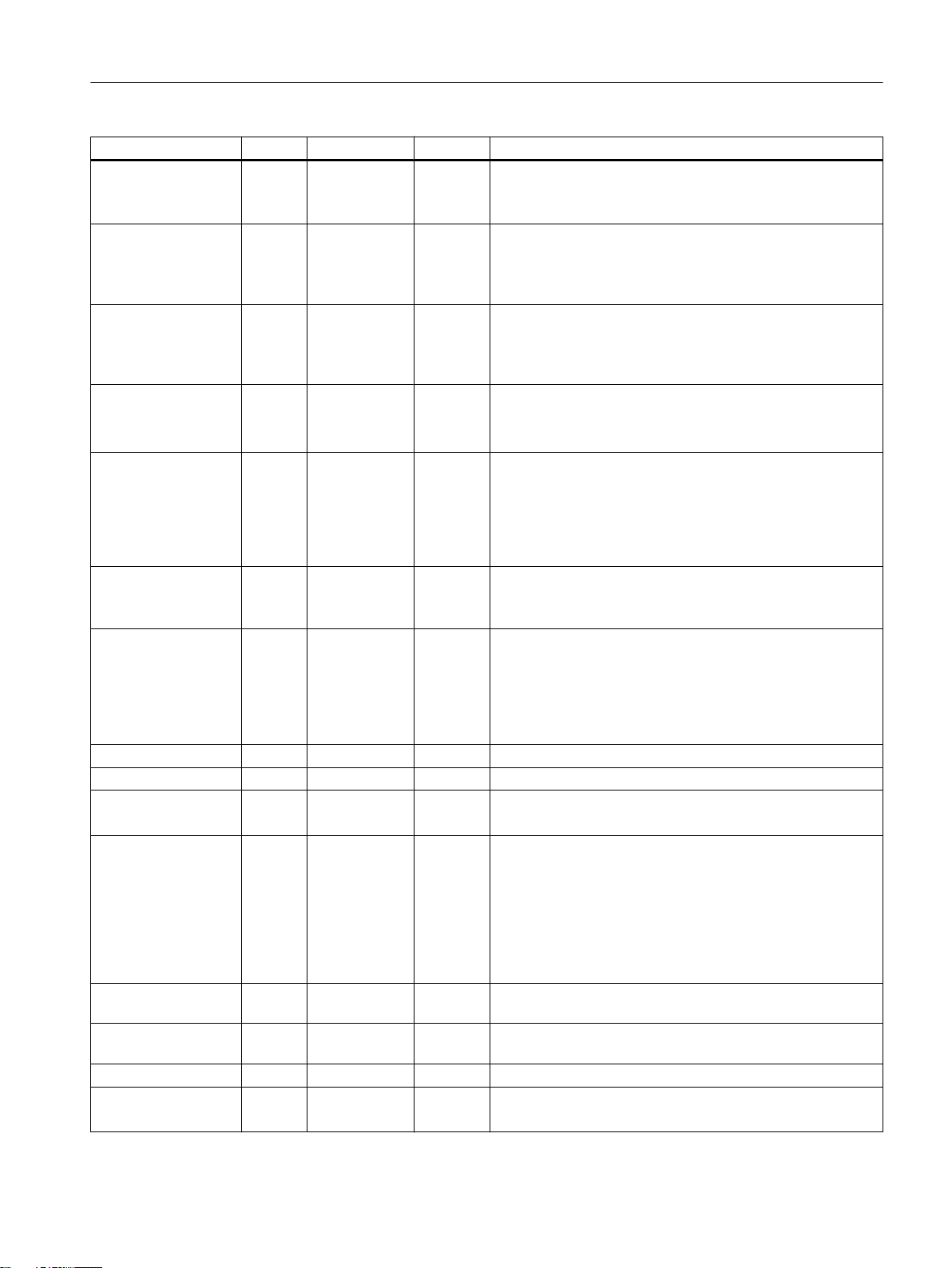
Table 3-1 Parameters of the _POSMOA_control function block
Name P type 1)Data type Default Meaning
pkwIn IN ARRAY [0..7]
of BYTE
pzdIn IN ARRAY [0..3]
of BYTE
enable IN BOOL FALSE Sets drive to ready for operation
homing IN BOOL FALSE Sets the home position
releaseBrake
4)
IN BOOL FALSE = TRUE: Release holding brake
jog1 IN BOOL FALSE Selection of jog 1
jog2 IN BOOL FALSE Selection of jog 2
jogOverride
veloOverride
3)
3)
IN INT 20 Speed override of jogging (0 to 100%)
IN INT 20 Velocity override (0 to 100%)
start IN BOOL FALSE = edge FALSE → TRUE: The traversing block specified in
singleBlock
enableRdIn
4)
4)
IN BOOL FALSE = TRUE: Automatic single block. Each block has to be re-
IN BOOL TRUE = TRUE: Read-in enable. Next block is enabled for execution.
8(16#00) Transfer I/O inputs of POSMO A to FB
4(16#00) Transfer I/O inputs of POSMO A to FB
The drive is now ready for operation provided there are no
faults.
This signal must be present for at least 50 ms.
= FALSE: Brake sequence control effective
If jog 1 and 2 are set simultaneously, a warning is issued and
the drive does not move.
If jog 1 and 2 are set simultaneously, a warning is issued and
the drive does not move.
The override can also be changed during travel.
This override can also be changed during travel.
blockNumber is started.
Once a block has been selected in blockNumber, the start
parameter cannot be set until the next block call.
started.
= FALSE: AUTOMATIC mode
= FALSE: Read-in disable
Supplement to SIMODRIVE POSMO A Positioning Motor
20 Function Manual, 01/2015
Page 21
Function blocks
3.2 Function block _POSMOA_control
Name P type 1)Data type Default Meaning
extBlockChange
noStopIntermediate IN BOOL FALSE = TRUE: No intermediate stop or block in intermediate stop
noStop IN BOOL FALSE = TRUE: No stop
blockNumber IN BYTE 16#00 Traversing block numbers 3 to 27
resetError IN BOOL FALSE Acknowledges fault
setStartInformation IN BYTE 16#00 Start byte
mdiMode
mdiVelocity
mdiAcceleration
mdiPosition
reqControl
pkwOut IN/OUT ARRAY [0..7]
pzdOut IN/OUT ARRAY [0..3]
busy IN/OUT BOOL - Coordination of the FBs
ready OUT BOOL FALSE Drive ready for operation
4)
IN BOOL FALSE = Edge FALSE → TRUE: The active block is interrupted and
the next block is selected.
= FALSE: No external block change
is resumed
= FALSE: Intermediate stop
Interruption of current travel requeststart is not accepted
= FALSE: Stop
Abort of current travel request If start parameter is set at the
same time, start is not accepted.
Single block or program
blockNumber = 3 → MDI operation
1. Remedy cause of fault.
2. FALSE → TRUE edge
3. Parameter must remain set to TRUE until driveError =
FALSE.
Bit combination transmitted to the drive as an additional start
requirement.
3)
IN BOOL FALSE = TRUE: MDI relative
2)
The value in the mdiPosition parameter is evaluated relative
to the current position
= FALSE: MDI absolute
The value in the mdiPosition parameter is evaluated in ab‐
solute terms relative to the drive zero position set by homing.
3)
3)
4)
IN INT 0 Velocity of MDI travel (0 to 100%)
3)
IN INT 0 Acceleration of MDI travel (0 to 100%)
IN REAL 0 Target position of MDI travel
Value range: -2 • 105 to 2 • 10
IN BOOL FALSE Control requested by the open-loop control
5
p701 = 1: Message frame substitution active
= TRUE: PROFIBUS data are taken over by the POSMO A
= FALSE: Data from the PROFIBUS are frozen; the data last
received are used
p701 = 0: Message frame substitution inactive. Behavior as
for POSMO A before software version V3.0
- Prepared FB data for I/O outputs of the POSMO A
of BYTE
- Prepared FB data for I/O outputs of the POSMO A
of BYTE
Logic operation: Status word bits 2 to 0
2)
Supplement to SIMODRIVE POSMO A Positioning Motor
Function Manual, 01/2015 21
Page 22
Function blocks
3.2 Function block _POSMOA_control
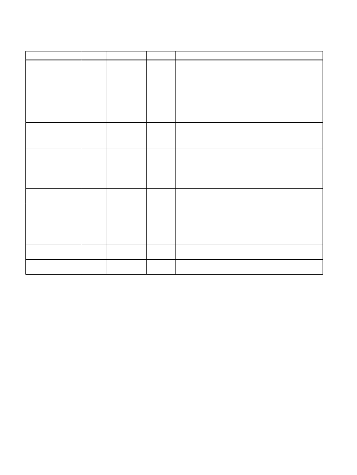
Name P type 1)Data type Default Meaning
active OUT BOOL FALSE = TRUE: Axis in motion
dataReady
statusWord OUT WORD 16#0000 Read out of status word
actBlockNumber OUT BYTE 16#00 Readout of current block number
statusInformation OUT BYTE 16#00 Checkback signal byte
driveWarning OUT BOOL FALSE A drive warning is pending
driveWarnId OUT WORD 16#0000 Reason for the warning
driveWarnInfo
driveError OUT BOOL FALSE A drive error is pending
driveErrorId OUT WORD 16#0000 Reason for the error
error OUT BOOL FALSE = TRUE: Request completed with error
errorID OUT WORD 16#0000 Number of the parameter assignment error signaled by the
1)
Parameter types: IN = input parameter, OUT = output parameter, IN/OUT = in/out parameter
2)
See
3)
This parameter is only transferred when the value of the parameter changes.
4)
As of SIMOTION V4.1, this parameter is part of the _POSMOA_control FB and can only be operated with POSMO A as of
software version V3.0.
4)
4)
Distributed Positioning Motor on PROFIBUS DP
OUT BOOL FALSE Several cycles are required for the transfer , for example, of
OUT WORD 16#0000 Warnings or supplementary information, corresponds to
user manual
mdiPosition and jogOverride
= TRUE: Data transfer completed (e.g. mdiPosition, jogO‐
verride,...)
= FALSE: Data transfer in progress (ramp-up time) or data
transfer not yet started
2)
Bit combination as additional status signal.
2)
(refer to parameter driveWarnId).
Bit format
Value corresponds to parameter 953 (warnings)
2)
p954 of the POSMO A
(refer to the driveErrorId parameter)
Bit format
Value corresponds to parameter 947 (errors)
2)
(refer to the errorID parameter)
drive (parameter identifier value (PKW) range)
2)
Message frame substitution (POSMO A as of software version V3.0)
For specific applications it is necessary that under no circumstances the drive comes
undesirably to a standstill or the drive state can be configured to "freeze" to run-down the
master (SIMOTION device).
The "Message frame substitution" function can be activated with the reqControl input
parameter using software version V3.0 or higher of the POSMO A, with parameter p701
= TRUE set.
The process data sent by the SIMOTION device are taken over by the POSMO A with
reqControl = TRUE. When the transition from TRUE to FALSE occurs on the reqControl input
parameter, the POSMO A uses the process data received most recently (control word, block
Supplement to SIMODRIVE POSMO A Positioning Motor
22 Function Manual, 01/2015
Page 23

Function blocks
3.2 Function block _POSMOA_control
selection and start byte). If parameter P701 = FALSE, the status of the reqControl input
parameter is not evaluated.
Note
The "Message frame substitution" function takes immediate effect when p701 = 1.
Make sure that it is possible to shut down the drive at any time using an EMERGENCY STOP.
For additional information, refer to the SIMODRIVE POSMO A user manual,
Positioning Motor on PROFIBUS DP
Task integration (call)
The _POSMOA_control function block must be called cyclically in the BackgroundTask or in
the TimerInterruptTask. Calling in the SystemInterruptTask is not permitted. Calling the
function block in synchronous tasks (e.g. IPOSynchronousTask) is not recommended for
runtime reasons.
Note
The functionality of the _POSMOA_control FB has been expanded with V4.1. To enable you
to use the newly implemented functions, you must add the new input parameters when calling
the _POSMOA_control FB.
If you want to work with the previous functions (< V4.1), you can leave out the new input
parameters with a detailed notation when calling the FB.
Error messages, faults and warnings
The TRUE value at the error output parameter indicates a parameterization error. The
errorID output parameter provides more detailed information on the parameterization error that
has occurred or has been signaled by POSMO A. Parameterization errors do not need to be
acknowledged. Changed parameters (e.g. ramp-up time) can be transferred again.
Distributed
.
Faults on the POSMO A are signaled in the driveError output parameter with the value
TRUE. The reason for the fault can be read out in the driveErrorId output parameter (value
corresponds to P947). Drive faults have to be acknowledged and must be reset in the
resetError input parameter with the rising edge!
Warnings pending from the POSMO A and the associated information are output in the
driveWarning, driveWarnId (value corresponds to P953) and driveWarnInfo (value
corresponds to P954) output parameters.
Supplement to SIMODRIVE POSMO A Positioning Motor
Function Manual, 01/2015 23
Page 24
SNZ,Q
S]G2XW
B32602$BQ&RQWURO
%22/
%22/
%22/
S]G,Q
LQLW
$55$<>@RI%<7(
$55$<>@RI%<7(
$55$<>@RI%<7(
$55$<>@RI%<7(
S]G2XW
:25'
',17
%22/
:25'
VWDWXV:RUG
UHDG\
DFW9DOXH
HUURU
HUURU,'
(1
(12
GDWD5HDG\
%22/
HQDEOH
UHOHDVH%UHDNH
DFFHO7LPH
UHOHDVH5DPS
VWDUW5DPS
VHWSRLQW
UHOHDVH6HWSRLQW
UHVHW(UURU
UHT&RQWURO
$55$<>@RI%<7(
%22/
$55$<>@RI%<7(
%22/
SNZ2XW
EXV\
SNZ2XW
EXV\
GULYH(UURU
GULYH(UURU,G
GULYH:DUQLQJ
GULYH:DUQ,G
GULYH:DUQ,QIR
%22/
:25'
%22/
:25'
:25'
%22/
',17
%22/
%22/
',17
%22/
%22/
%22/
%22/
DFWLYH
/$'VSHFLILFSDUDPHWHUV
Function blocks
3.3 Function block _POSMOA_nControl
3.3 Function block _POSMOA_nControl
Task
You can control the connected SIMODRIVE POSMO A in speed-controlled mode with the
_POSMOA_nControl function block.
Note
The _POSMOA_nControl function block is contained in SIMOTION SCOUT as of V4.1.
The technology objects (TOs) cannot be used to operate the POSMO A via the speed setpoint
interface.
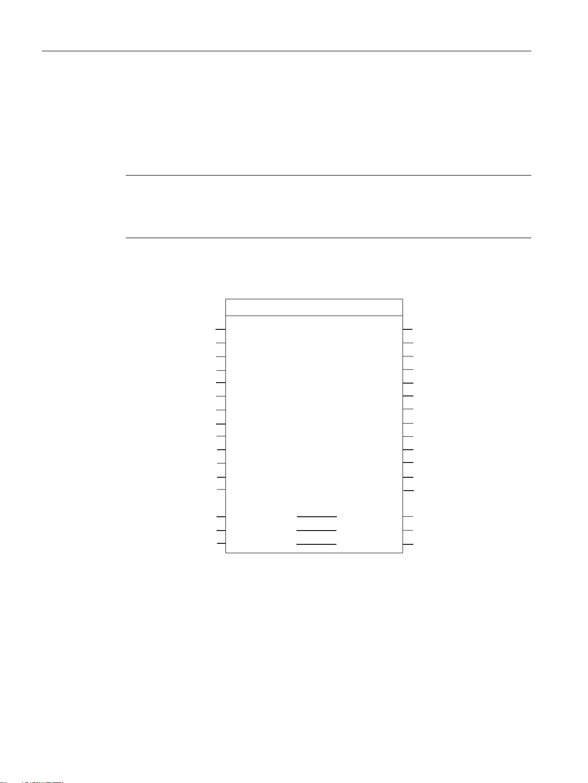
Call (LAD representation)
24 Function Manual, 01/2015
Supplement to SIMODRIVE POSMO A Positioning Motor
Page 25
Function blocks
3.3 Function block _POSMOA_nControl
Parameter description
Note
The busy parameter must not be overwritten by the user. It is supplied and checked by the
function block, and must be supplied with a global variable created by the user only when the
respective function block is called. This parameter coordinates the individual function blocks
for the POSMO A. This ensures that no more than one function block can access a POSMO A
at the same time.
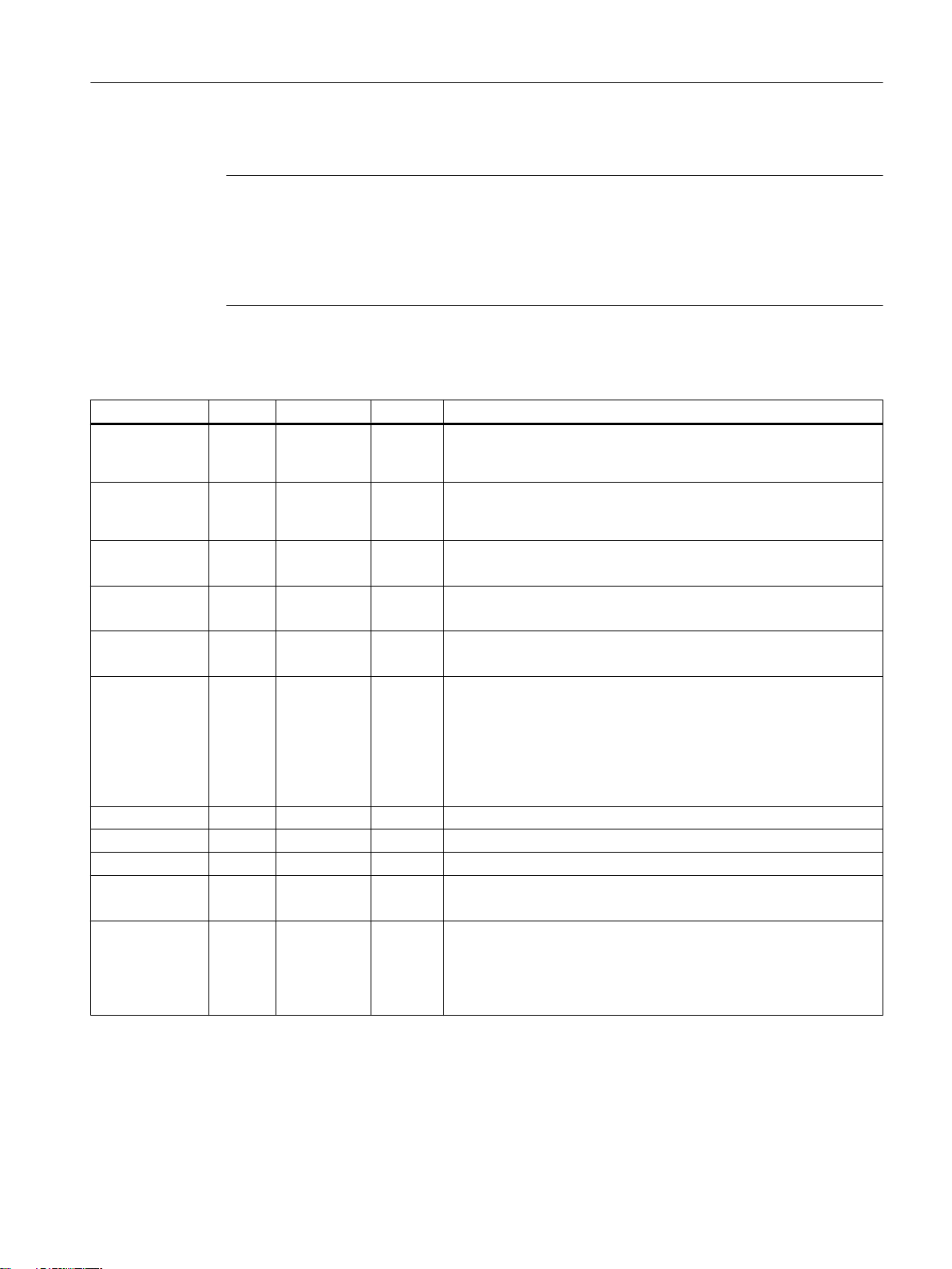
Table 3-2 Parameters of the _POSMOA_nControl function block
Name P type 1)Data type Default Meaning
pkwIn IN AR‐
RAY[0..7] of
BYTE
pzdIn IN AR‐
RAY[0..3] of
BYTE
init IN BOOL FALSE = TRUE: Sets the drive to "Ready to start"
enable IN BOOL FALSE = TRUE: Sets the drive to "Ready for operation"
releaseBrake IN BOOL FALSE = TRUE: Release holding brake
accelTime IN DINT 0 Ramp-up/ramp-down time [ms]
releaseRamp IN BOOL FALSE = TRUE: Release ramp-function generator output
startRamp IN BOOL FALSE = Edge FALSE → TRUE: Start ramp-function generator
setpoint IN INT 0 Speed setpoint
releaseSetpoint IN BOOL FALSE Setpoint release
resetError IN BOOL FALSE Acknowledge error
8(16#00) Transfer I/O inputs of POSMO A to _POSMOA_nControl FB
4(16#00) Transfer I/O inputs of POSMO A to FB
STW = 0x040E
The drive is now ready for operation (provided there are no errors).
= FALSE: Brake sequence control effective
During this time, the setpoint is adjusted in speed-controlled mode
as follows:
● Ramp-up: From zero to the maximum permissible actual speed
● Ramp-down: From the maximum permissible actual speed to
zero
= TRUE: Setpoint released
1. Remedy cause of error
2. FALSE → TRUE edge
3. Parameter must remain set to TRUE until driveError = FALSE.
Supplement to SIMODRIVE POSMO A Positioning Motor
Function Manual, 01/2015 25
Page 26
Function blocks
3.3 Function block _POSMOA_nControl
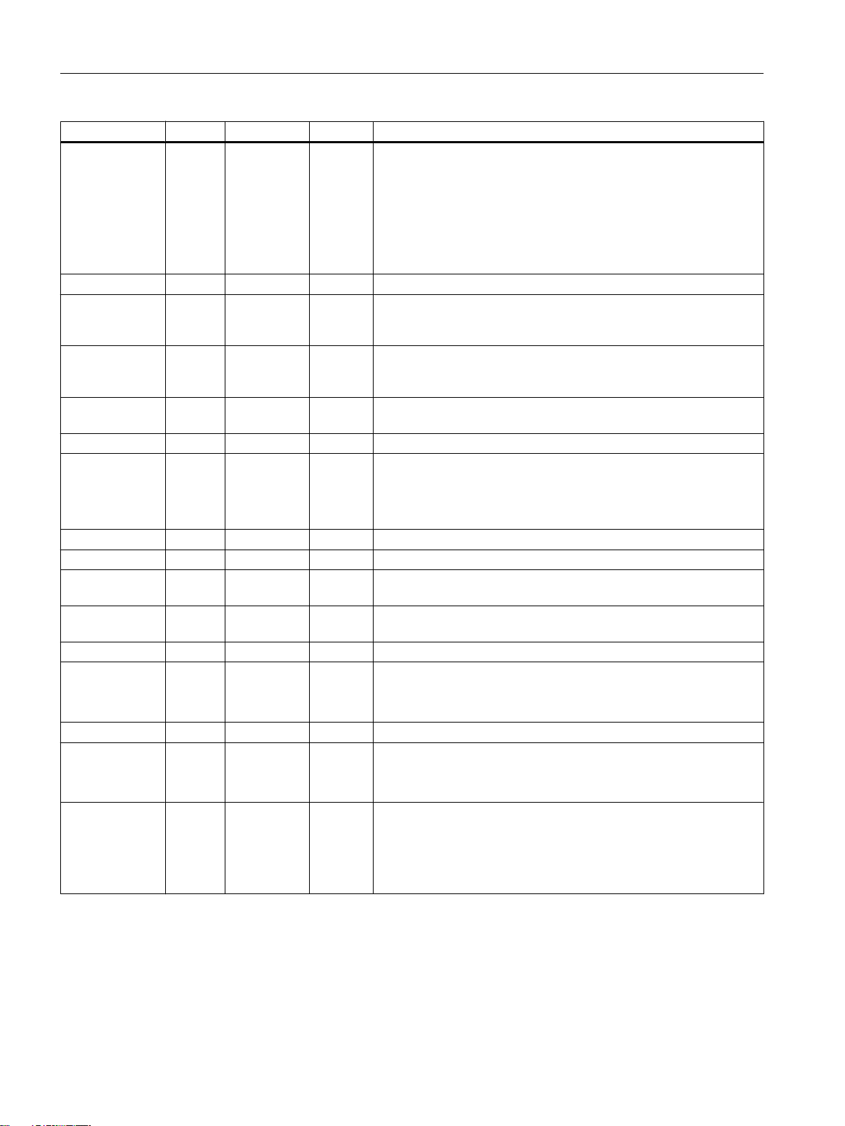
Name P type 1)Data type Default Meaning
reqControl IN BOOL FALSE Control requested by the open-loop control
p701 = 1: Message frame substitution active
= TRUE: PROFIBUS data are taken over by the POSMO A
= FALSE: Data from the PROFIBUS are frozen; the most recent data
received are used
p701 = 0: Message frame substitution inactive. Behavior as with
POSMO A before software version V3.0
busy IN/OUT BOOL - Coordination of the function blocks
pkwOut IN/OUT AR‐
RAY[0..7] of
BYTE
pzdOut IN/OUT AR‐
RAY[0..3] of
BYTE
ready OUT BOOL FALSE Drive ready for operation,
active OUT BOOL FALSE = TRUE: Drive traveling (n > 0)
dataReady OUT BOOL FALSE Several cycles are required for transferring the ramp-up time, for ex‐
statusWord OUT WORD 16#0000 Display of status word
actValue OUT DINT 0 Actual speed
error OUT BOOL FALSE = TRUE: Request completed with error
errorID OUT WORD 16#0000 Number of the parameter assignment error signaled by the drive
driveError OUT BOOL FALSE Drive error is pending
driveErrorId OUT WORD 16#0000 Reason for the error
driveWarning OUT BOOL FALSE A drive warning is pending (refer to parameter driveWarnId).
driveWarnId OUT WORD 16#0000 Reason for the warning
driveWarnInfo OUT WORD 16#0000 Supplementary information for warnings (for POSMO A, firmware
1)
Parameter types: IN = input parameter, OUT = output parameter, IN/OUT = in/out parameter
2)
See
Distributed Positioning Motor on PROFIBUS DP
- Prepared FB data for I/O outputs of the POSMO A (parameter iden‐
tifier value interface)
- Prepared FB data for I/O outputs of the POSMO A (process data
interface)
AND operation: Status word bit 2, bit 1, bit 0
ample. Completion of the data transfer is indicated by a rising edge.
= TRUE: Data transfer finished, data have been transferred
= FALSE: Data transfer in progress (e.g. ramp-up time)
(refer to the errorID parameter)
(parameter identifier value (PKW) range)
2)
Bit format
Value corresponds to parameter 947 (errors)
2)
Bit format
Value corresponds to parameter 953 (warnings)
2)
version 1.4 and higher)
Bit format
The value corresponds to P954, (supplementary information for
warnings)
user manual
Supplement to SIMODRIVE POSMO A Positioning Motor
26 Function Manual, 01/2015
Page 27

Function description
The POSMO A is set to the "ready to start" state (control word 0x040E) with the TRUE level
on the init input parameter. The "ready to start" state is displayed in the output parameter
statusWord, bit 0 = TRUE. When the transition from FALSE to TRUE level occurs at the input
parameter enable, the drive is set to "ready for operation". The POSMO A changes to the
"ready for operation" state, which can be read out on the output parameter ready = TRUE.
Traversing is started when the input parameters enableSetpoint = TRUE,
enableRamp = TRUE, (enable ramp-function generator) execRamp = TRUE (start rampfunction generator) with a positive edge, and setpoint > 0.
The order in which the input parameters enable, enableSetpoint, enableRamp, and
execRamp are set for starting traversing is at the user's discretion. The input parameters
specified above have equal status. Traversing stops when the input parameters enable,
enableSetpoint, enableRamp, and execRamp are reset.
Transferring parameters (e.g. ramp-up time - input parameter accelTime) requires several task
cycles. If a new value is parameterized at the accelTime input parameter, the output parameter
dataReady is set to FALSE. Any pending parameter errors (output parameter error = TRUE)
are reset. Data transfer is performed as soon as the in/out parameter busy = FALSE. If data
transmission was active when the accelTime input parameter was newly parameterized (e.g.
read parameter with _POSMOA_rwParameter FB), data transfer is suspended until busy
= FALSE. The value which was parameterized when busy = TRUE changed to busy
= FALSE at the input parameter accelTime is transferred. Completion of data transfer is
displayed with a rising edge at the output parameter dataReady and stays at TRUE until the
next data transfer is started.
Function blocks
3.3 Function block _POSMOA_nControl
Message frame substitution (POSMO A, software version V3.0 and higher)
With certain applications, it is essential that the drive be prevented from coming to an
undesirable standstill under all circumstances, or that "freezing" of the drive status can be
configured for the purpose of shutting down the master (SIMOTION device).
The "Message frame substitution" function can be activated with the reqControl input
parameter as of software version V3.0 of the POSMO A with set parameter p701 = TRUE.
The process data sent by the SIMOTION device are taken over by the POSMO A with
reqControl = TRUE. With the transition from TRUE to FALSE on the reqControl input
parameter, the POSMO A uses the process data received last (control word, block selection
and start byte). If parameter P701 = FALSE, the status of the reqControl input parameter is
not evaluated.
Note
The "Message frame substitution" function takes effect immediately with p701 = 1!
Make sure that the drive can be shut down at any time by an EMERGENCY STOP.
For more information, refer to the SIMODRIVE POSMO A user manual,
Motor on PROFIBUS DP
.
Distributed Positioning
Supplement to SIMODRIVE POSMO A Positioning Motor
Function Manual, 01/2015 27
Page 28
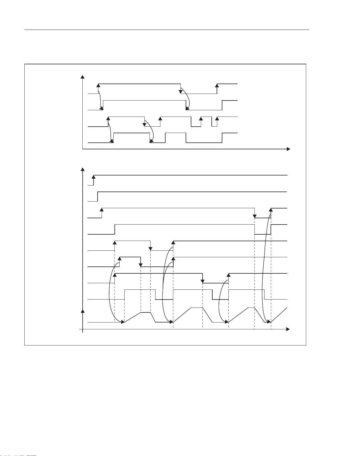
LQLW
HQDEOH
UHDG\
UHOHDVH5DPS
VWDUW5DPS
UHOHDVH6HWSRLQW
VWDWXV:RUG%LW
(LQVFKDOWELW
LQLW
HQDEOH
UHDG\
VWDWXV:RUG%LW
(LQVFKDOWELW
9
6WDWXVZRUGELW
GULYHWUDYHOLQJ
9HORFLW\
/HYHO
7LPH
/HYHO
7LPH
Function blocks
3.3 Function block _POSMOA_nControl
Graphical overview of the functionality
Figure 3-1 Signal propagation diagram
Task integration (call)
The _POSMOA_nControl function block must be called cyclically in the BackgroundTask or in
the TimerInterruptTask. Calling in the SystemInterruptTask is not permitted. Calling the
function block in synchronous tasks (e.g. IPOSynchronousTask) is not recommended for
28 Function Manual, 01/2015
runtime reasons.
Supplement to SIMODRIVE POSMO A Positioning Motor
Page 29
3.4 Function block _POSMOA_rwParameter
Error messages, errors, and warnings
The TRUE value at the error output parameter indicates a parameterization error. The
errorID output parameter provides more detailed information on the parameterization error that
has occurred. Parameterization errors do not need to be acknowledged. Parameters that have
been changed (e.g. ramp-up time) can be transferred again.
Errors in the POSMO A are signaled in the driveError output parameter with the value TRUE.
The reason for the error can be read out in the driveErrorId output parameter (value
corresponds to P947). Drive errors have to be acknowledged and must be reset in the
resetError input parameter with a rising edge.
Warnings from the POSMO A that are pending, and their associated information, are output
in the driveWarning, driveWarnId (value corresponds to P953), and driveWarnInfo (value
corresponds to P954) output parameters.
3.4 Function block _POSMOA_rwParameter
Task
Function blocks
The _POSMOA_rwParameter function block enables parameters to be assigned for the
connected SIMODRIVE POSMO A.
The functions are as follows:
● Reading a parameter: Provides the value of the specified parameter.
● Writing a parameter value: Sets the specified parameter to the specified value.
● Loading factory settings: Resets the parameter configuration to the factory settings.
● Saving a parameter: Saves the current parameter configuration in non-volatile memory.
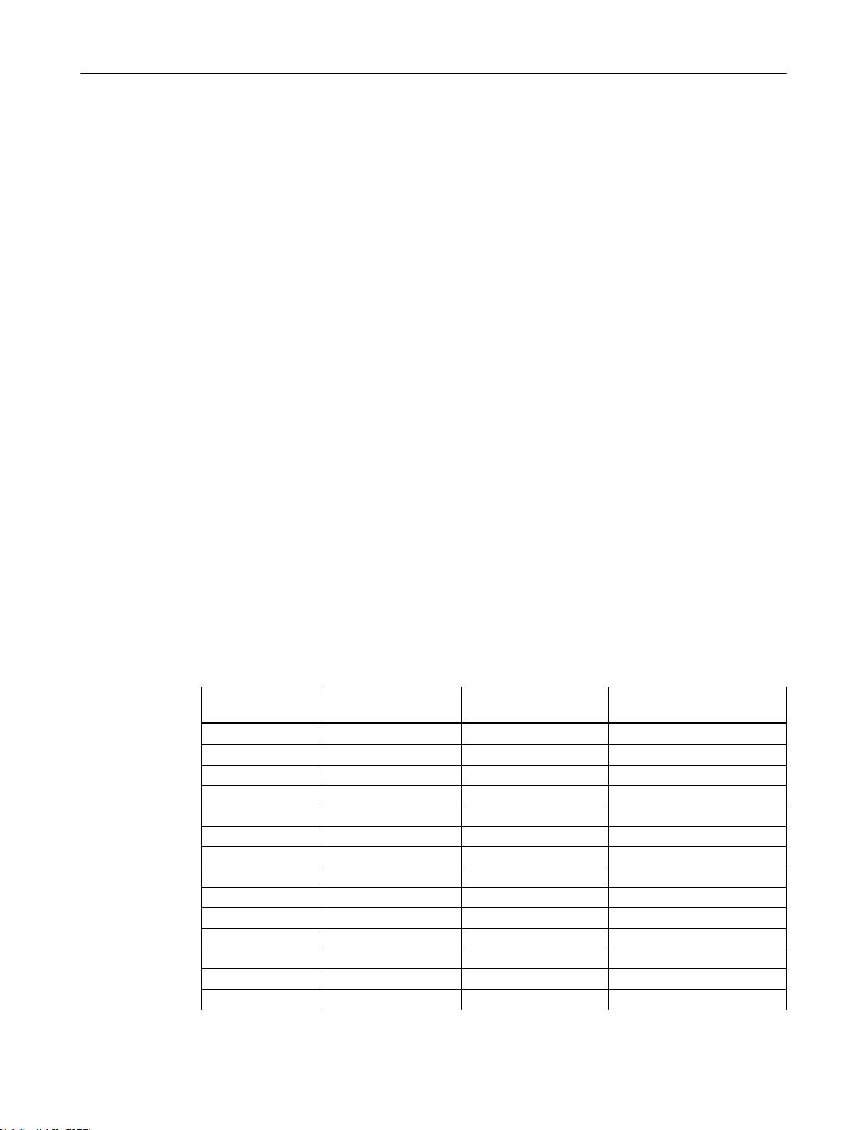
The following parameters can be read/written with this function block:
Parameter numbers Read from POSMO A Write to POSMO A
(positioning mode)
1...5 Yes Yes Yes
6...7 Yes Yes No
9...23 Yes Yes Yes
24 Yes Yes No
25...38 Yes Yes Yes
39...53 Yes No No
54 Yes Yes Yes
55 Yes No No
56...61 Yes Yes Yes
62 Yes No No
80:28...87:28 Yes Yes Yes
99:21 Yes Yes Yes
100 Yes Yes No
101:11 Yes Yes No
Write to POSMO A
(speed-controlled mode)
Supplement to SIMODRIVE POSMO A Positioning Motor
Function Manual, 01/2015 29
Page 30
SNZ,Q
UHDO9DOXH
B32602$BUZ3DUDPHWHU
H[HF:ULWH
HQDEOH5HDG
%22/
GRQH
%22/
86,17
%22/
SNZ2XW
EXV\
SDUD1XPEHU
VXELQGH[
5($/
8,17
VHW'HIDXOW
%22/
VDYH3DUDPHWHU
%22/
%22/
SNZ2XW$55$<>@RI%<7(
HUURU
%22/
HUURU,'
:25'
EXV\
UHDO9DOXH
%22/
5($/
GLQW9DOXH
',17
GLQW9DOXH
',17
(1
(12
/$'VSHFLILFSDUDPHWHUV
$55$<>@RI%<7(
$55$<>@RI%<7(
Function blocks
3.4 Function block _POSMOA_rwParameter
Parameter numbers Read from POSMO A Write to POSMO A
1)
700
1)
701
1)
880
918...928 No No No
930 Yes No No
947...954 No No No
964:8 Yes No No
967...990:78 No No No
1)
1426
1)
1427
1)
This parameter is new or extended with SIMOTION V4.1.
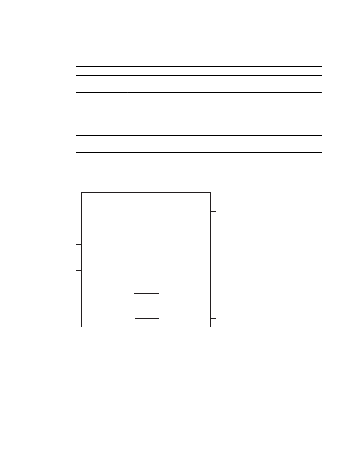
Call (LAD representation)
Write to POSMO A
(positioning mode)
(speed-controlled mode)
Yes Yes Yes
Yes Yes Yes
Yes Yes Yes
Yes Yes Yes
Yes Yes Yes
30 Function Manual, 01/2015
Supplement to SIMODRIVE POSMO A Positioning Motor
Page 31
Parameter description
Note
The SIMOTION identifiers have changed as of V4.0.
You can find a comparison of SIMOTION and SIMATIC names in the Appendix SIMOTION
and SIMATIC names (Page 51).
The busy parameter must not be overwritten by the user. It is supplied and checked by the
function block, and must be supplied with a global variable created by the user only when the
respective function block is called. This parameter coordinates the individual function blocks
for the POSMO A. This ensures that no more than one function block can access a POSMO A
at the same time.
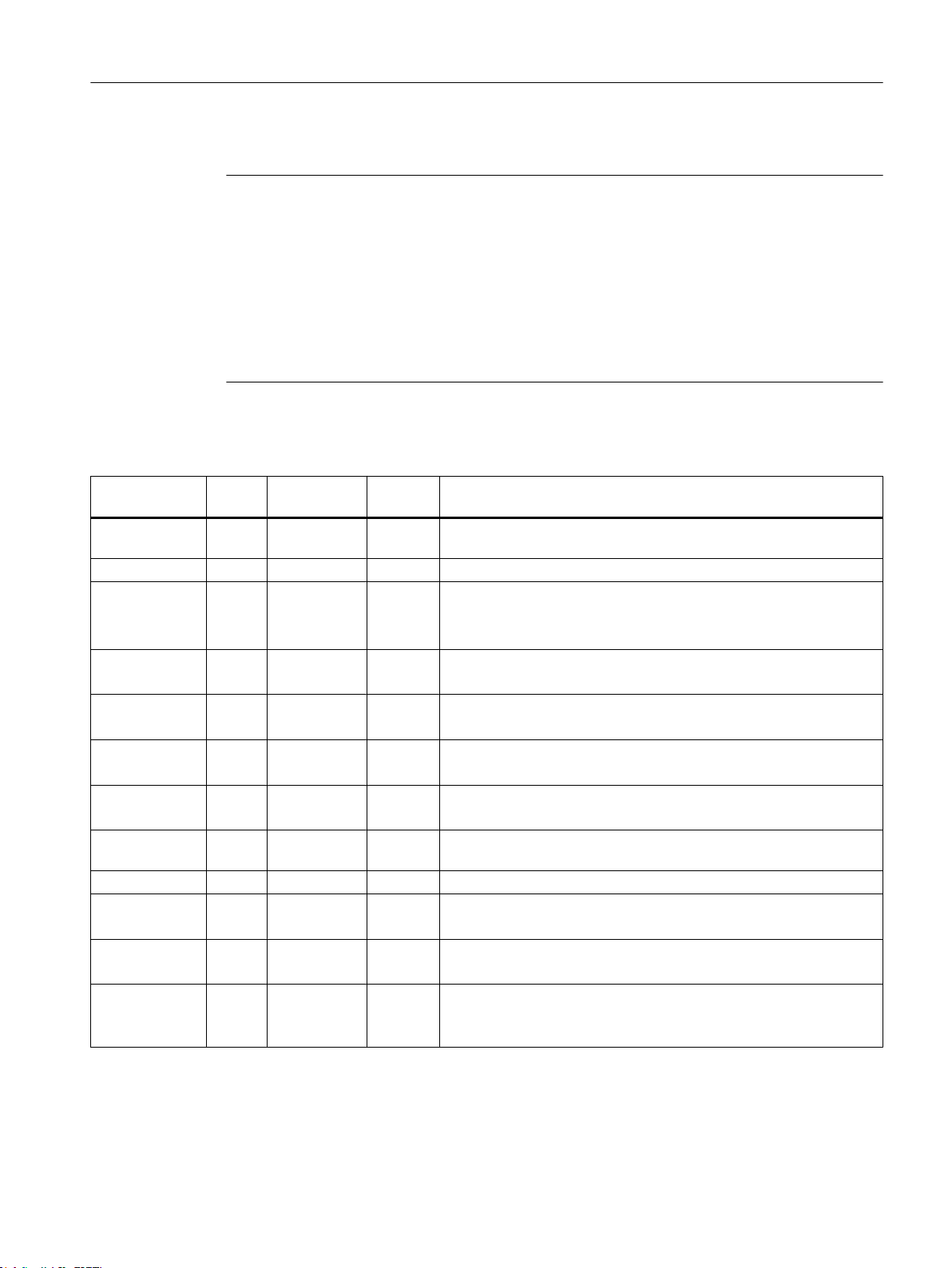
Table 3-3 Parameters of the _POSMOA_rwParameter function block
Name P type 1)Data type Default Meaning
Function blocks
3.4 Function block _POSMOA_rwParameter
pkwIn IN ARRAY [0..7]
8(16#00) Transfer I/O inputs of POSMO A to FB
of BYTE
paraNumber IN UINT 0 Parameter number to be read or written
subindex IN USINT 0 Subindex
= 0 for parameters with no index
This value is the array index for parameters with an array.
enableRead IN BOOL FALSE = TRUE: Reads parameter cyclically
= edge FALSE → TRUE: Reads parameter one time
execWrite IN BOOL FALSE = edge FALSE → TRUE: Writes parameter
When set simultaneously with enableRead, read is executed.
setDefault IN BOOL FALSE = edge FALSE → TRUE: Loads factory settings
When set simultaneously with enableRead, read is executed.
saveParameter IN BOOL FALSE = edge FALSE → TRUE: Saves parameter
When set simultaneously with enableRead, read is executed.
pkwOut IN/OUT ARRAY [0..7]
- Prepared FB data transferred to the I/O outputs of the POSMO A
of BYTE
busy IN/OUT BOOL - Coordination of the FBs
realValue IN/OUT REAL - Write → value to be written (data types C4 and N2)
Read → value to be read (data types C4 and N2)
2)
2)
dintValue IN/OUT DINT - Write → value to be written (data types I2, T2, V2 and T4)
Read → value to be read (data types I2, T2, V2 and T4)
done OUT BOOL FALSE = TRUE: When current request has been completed
= FALSE: There is no request pending, or a request is being execu‐
ted.
2)
2)
2)
Supplement to SIMODRIVE POSMO A Positioning Motor
Function Manual, 01/2015 31
Page 32
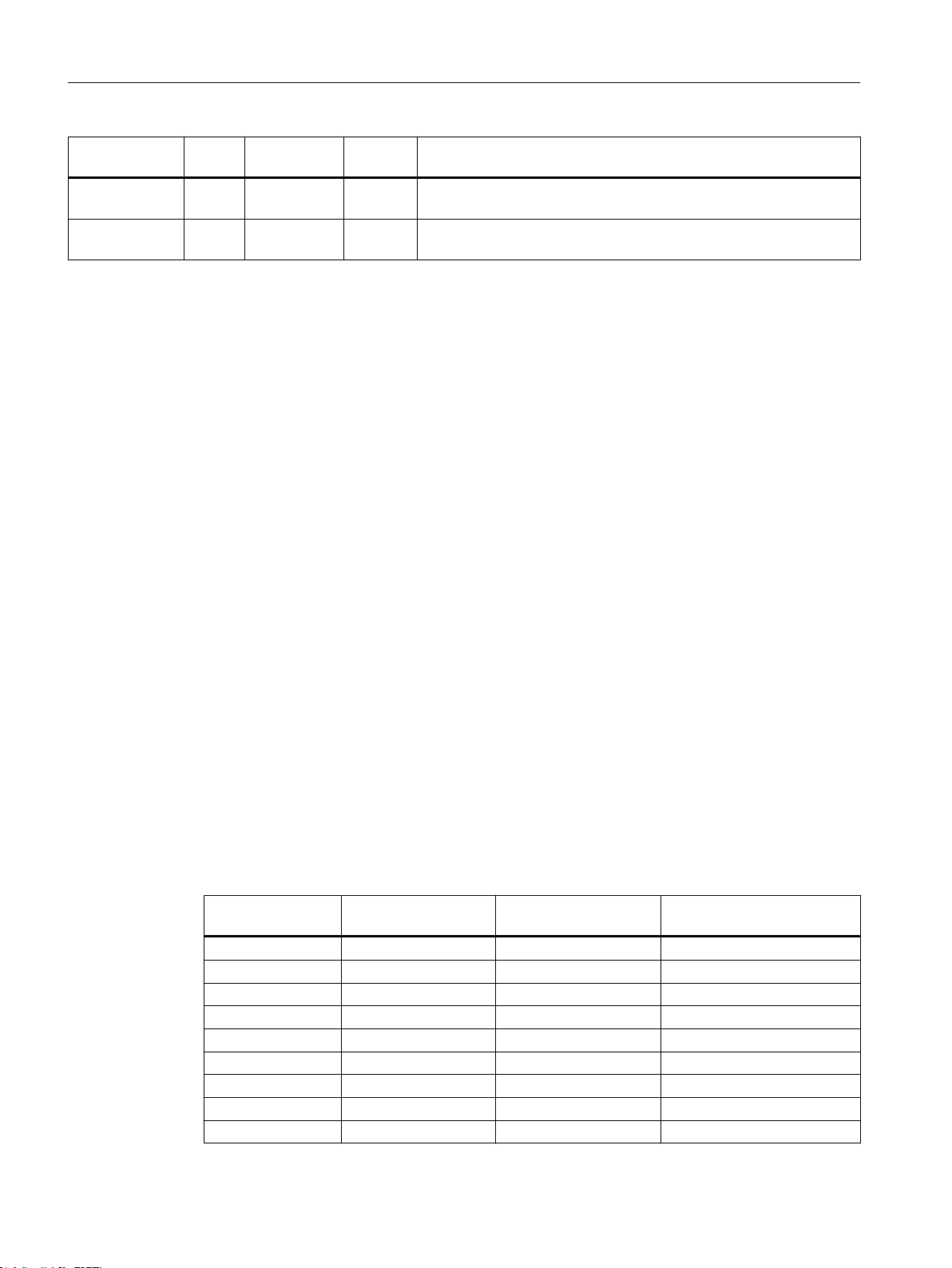
Function blocks
3.5 Function block _POSMOA_rwAllParameter
Name P type 1)Data type Default Meaning
error OUT BOOL FALSE = TRUE: Request completed with error (refer to the errorID parame‐
ter)
errorID OUT WORD 16#0000 Number of the parameter assignment error signaled by the drive (pa‐
rameter identifier value (PKW) range)
1)
Parameter types: IN = input parameter, OUT = output parameter, IN/OUT = in/out parameter
2)
See
Distributed Positioning Motor on PROFIBUS DP
user manual
2)
Task integration (call)
The _POSMOA_rwParameter function block must be called cyclically in the
BackgroundTask or in the TimerInterruptTask. Calling in the SystemInterruptTask is not
permitted. Calling the function block in synchronous tasks (e.g. IPOSynchronousTask) is not
recommended for runtime reasons.
Fault messages
The TRUE value at the error output parameter indicates a parameterization error. The
errorID output parameter provides more detailed information on the parameterization error that
has occurred or has been signaled by POSMO A. Parameterization errors do not need to be
acknowledged. Changed parameters (e.g. ramp-up time) can be transferred again.
3.5 Function block _POSMOA_rwAllParameter
Task
The _POSMOA_rwAllParameter function block enables reading and writing of the parameter
block of the connected SIMODRIVE POSMO A.
The data to be read or written are saved in a variable created by the user with the
Struct_POSMOA_params data structure when the associated function block instance is
called.
The following parameters are read/written with this function block:
Parameter numbers Read from POSMO A Write to POSMO A
(positioning mode)
1...5 Yes Yes Yes
6...7 Yes Yes No
9...23 Yes Yes Yes
24 Yes Yes No
25...38 Yes Yes Yes
39...53 Yes No No
54 Yes Yes Yes
55 Yes No No
56...61 Yes Yes Yes
Write to POSMO A
(speed-controlled mode)
Supplement to SIMODRIVE POSMO A Positioning Motor
32 Function Manual, 01/2015
Page 33
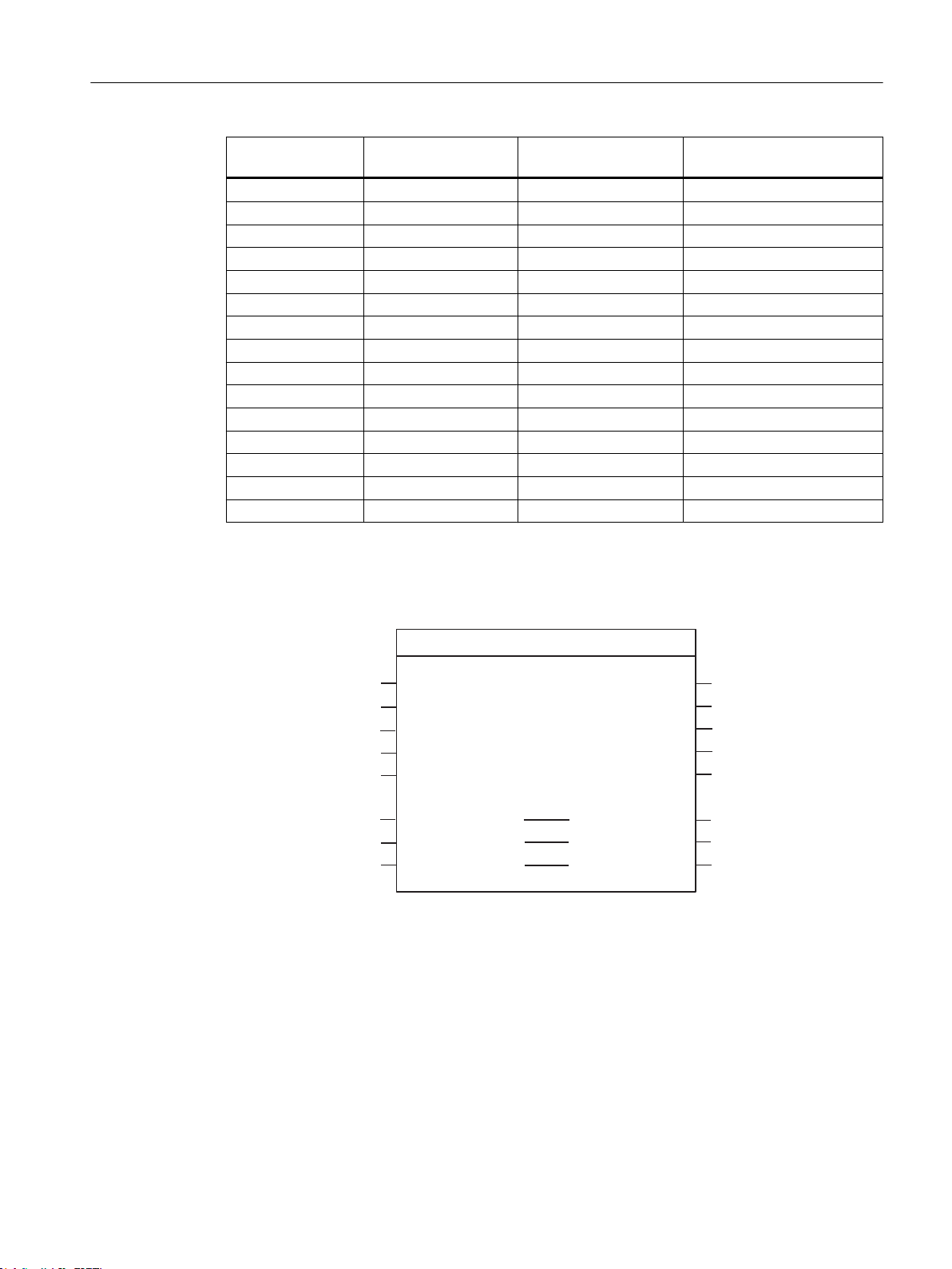
(1
SNZ,Q
EXV\
B32602$BUZ$OO3DUDPHWHU
%22/
GRQH
%22/
SNZ2XW
DOO3DUD3RVPR$
H[HF5HDG
H[HF:ULWH
$55$<>@RI%<7(
%22/
$55$<>@RI%<7(
%22/
6WUXFWB32602$BSDUDPV
SNZ2XW
$55$<>@RI%<7(
HUURU
%22/
HUURU,'
:25'
,17
HUURU3DUD1XPEHU
6WUXFWB32602$BSDUDPVDOO3DUD3RVPR$
EXV\
%22/
(12
SRV0RGH
%22/
/$'VSHFLILFSDUDPHWHUV
Function blocks
3.5 Function block _POSMOA_rwAllParameter
Parameter numbers Read from POSMO A Write to POSMO A
62 Yes No No
80:28...87:28 Yes Yes Yes
99:21 Yes Yes Yes
100 Yes Yes No
101:11 Yes Yes No
1)
700
1)
701
1)
880
918...928 No No No
930 Yes No No
947...954 No No No
964:8 Yes No No
967...990:116 No No No
1)
1426
1)
1427
1)
This parameter is new or extended with SIMOTION V4.1.
Call (LAD representation)
Write to POSMO A
(positioning mode)
(speed-controlled mode)
Yes Yes Yes
Yes Yes Yes
Yes Yes Yes
Yes Yes Yes
Yes Yes Yes
Supplement to SIMODRIVE POSMO A Positioning Motor
Function Manual, 01/2015 33
Page 34
Function blocks
3.5 Function block _POSMOA_rwAllParameter
Parameter description
Note
The SIMOTION identifiers have changed as of V4.0.
You can find a comparison of SIMOTION and SIMATIC names in the Appendix SIMOTION
and SIMATIC names (Page 51).
The busy parameter must not be overwritten by the user. It is supplied and checked by the
function block, and must be supplied with a global variable created by the user only when the
respective function block is called. This parameter coordinates the individual function blocks
for the POSMO A. This ensures that no more than one function block can access a POSMO A
at the same time.
Table 3-4 Parameters of the _POSMOA_rwAllParameter function block
Name P type 1)Data type Default Meaning
pkwIn IN ARRAY [0..7] of
BYTE
execRead IN BOOL FALSE = edge FALSE → TRUE: Reads all data one time
execWrite IN BOOL FALSE = edge FALSE → TRUE: Writes all data one time
posMode
3)
IN BOOL TRUE = TRUE: Positioning mode of the POSMO A
pkwOut IN/OUT ARRAY [0..7] of
BYTE
allParaPosmoA IN/OUT Struct_POS‐
MOA_params
busy IN/OUT BOOL - Coordination of the FBs
done OUT BOOL FALSE = TRUE: When current request has been completed
error OUT BOOL FALSE = TRUE: Request completed with error (refer to the errorID
errorID OUT WORD 16#0000 Number of the parameter assignment error signaled by the
errorParaNumber OUT INT 0 Number of the parameter that caused the error
1)
Parameter types: IN = input parameter, OUT = output parameter, IN/OUT = in/out parameter
2)
See
Distributed Positioning Motor on PROFIBUS DP
3)
As of SIMOTION V4.1, this parameter is part of the _POSMOA_rwAllParameter FB and can only be operated with POSMO A
software version 3.0 and higher.
8(16#00) Transfer I/O inputs of POSMO A to FB
The start takes place on a positive edge.
The start takes place on a positive edge.
= FALSE: Speed-controlled mode
- Prepared FB data for I/O outputs of the POSMO A
- Data structure for all parameters of the POSMO A
= FALSE: There is no request pending, or a request is being
executed.
parameter)
drive (parameter identifier value (PKW) range)
2)
2)
user manual
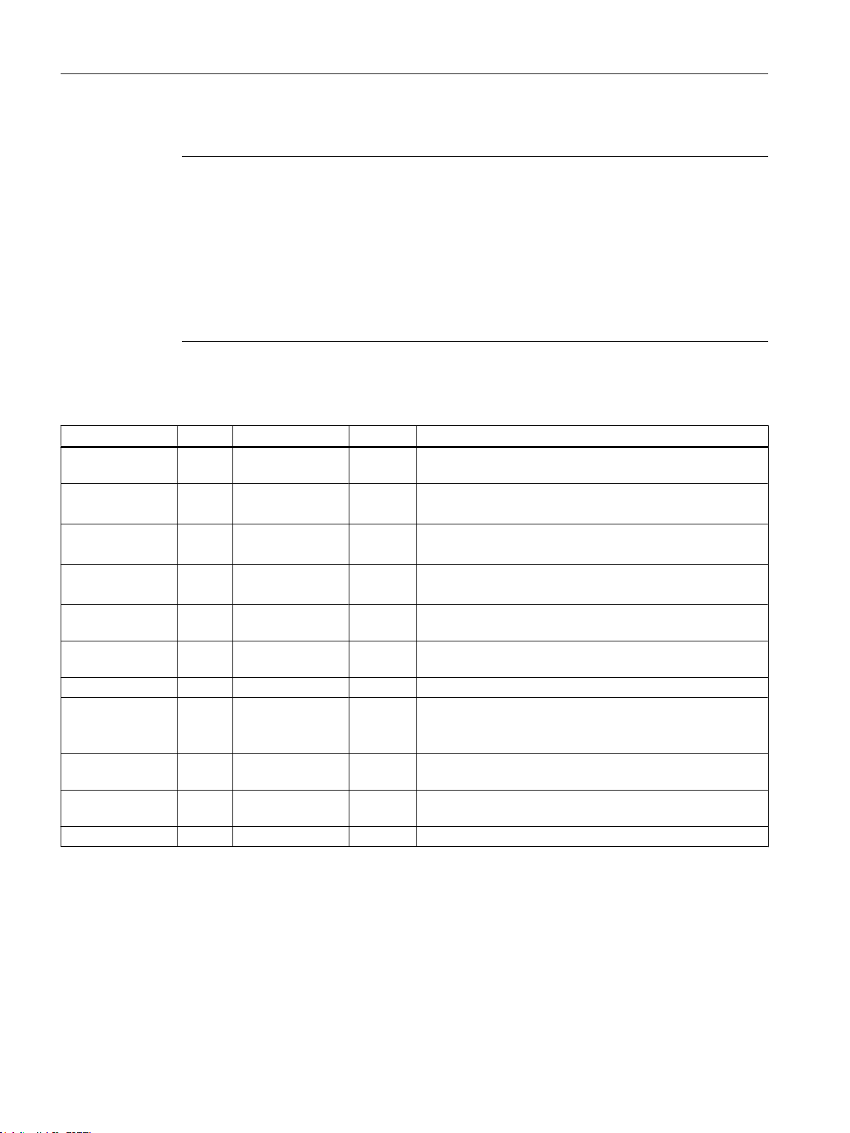
Data structure of Struct_POSMOA_params
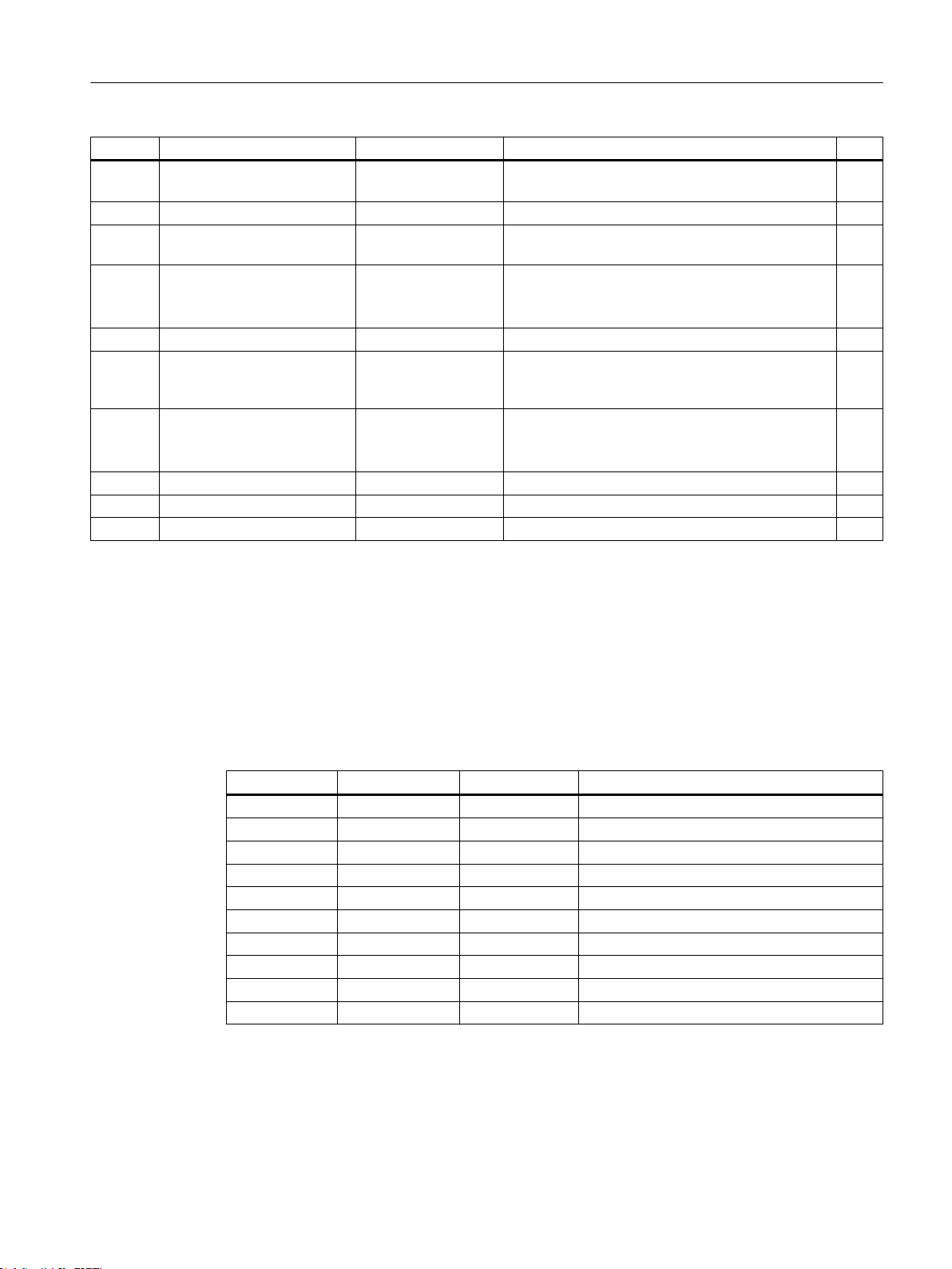
The data structure of type Struct_POSMOA_params contains all of the parameters for
controlling the SIMODRIVE POSMO A.
Supplement to SIMODRIVE POSMO A Positioning Motor
34 Function Manual, 01/2015
Page 35
Function blocks
3.5 Function block _POSMOA_rwAllParameter
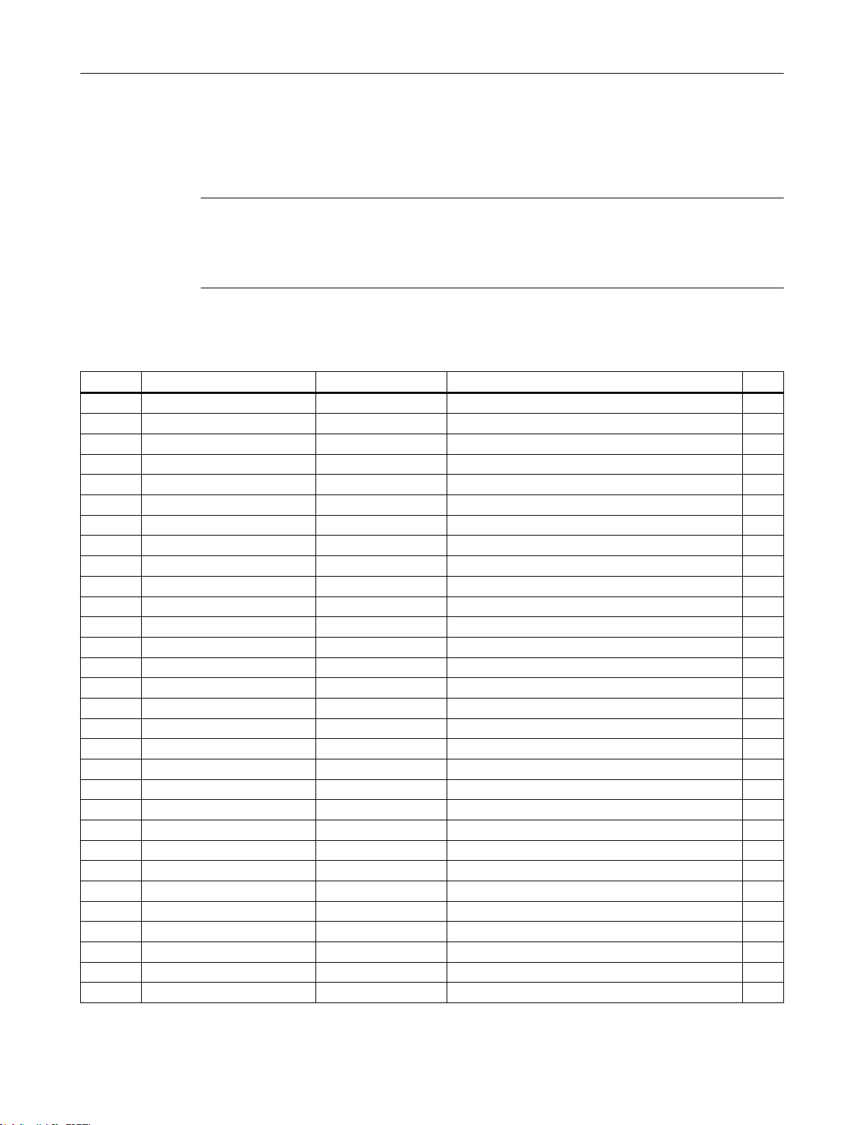
This data structure is used by the _POSMOA_rwAllParameter function block. Self-defined
variables of data type Struct_POSMOA_params are used to access data structure elements.
The following table contains the Struct_POSMOA_params data structure.
Note
The SIMOTION identifiers have changed as of V4.0.
You can find a comparison of SIMOTION and SIMATIC names in the Appendix SIMOTION
and SIMATIC names (Page 51).
Table 3-5 Data structure of Struct_POSMOA_params
Name Type Initial value Comment r/w
p1 REAL 0.0 Linear/rotary axis r/w
p2 REAL 10.0 Travel per gear revolution r/w
p3 REAL 1.0 Gear reduction factor r/w
p4 INT 0 Unit of measure r/w
p5 REAL 0.0 Position at home position r/w
p6 REAL -200000.0 Start of software limit switch r/w
p7 REAL 200000.0 End of software limit switch r/w
p8 REAL 3000.0 Maximum rotation speed r/w
p9 INT 10 Rampup time r/w
p10 DINT 30000 Maximum velocity r/w
p11 REAL 2.0 Target area r/w
p12 REAL 20000.0 Maximum following error r/w
p13 DINT 50 Monitoring time r/w
p14 REAL 20000.0 Zero speed area r/w
p15 REAL 0.0 Backlash on reversal compensation r/w
p16 REAL 9.0 Maximum overcurrent r/w
p17 DINT 20 P-gain of speed controller r/w
p18 INT 22 Integral time of speed controller r/w
p19 REAL 1.0 KV factor r/w
p20 REAL 30.0 Current setpoint smoothing r/w
p21 REAL 2.0 Rotation speed setpoint smoothing r/w
p22 REAL 1000.0 Maximum acceleration r/w
p23 DINT 0 Jerk time constant r/w
p24 INT 100 Override r/w
p25 INT 100 Acceleration override r/w
p26 INT 20 Rotation speed override for jogging r/w
p27 INT 50 Acceleration override for jogging r/w
p28 REAL 9.0 Maximum current r/w
p29 DINT 12000 Electronics temperature tolerance time r/w
p30 INT 0 Interference suppression r/w
1)
Supplement to SIMODRIVE POSMO A Positioning Motor
Function Manual, 01/2015 35
Page 36

Function blocks
3.5 Function block _POSMOA_rwAllParameter
Name Type Initial value Comment r/w
p31 INT 0 Terminal 1 function r/w
p32 INT 0 Terminal 2 function r/w
p33 DINT 0 Address for measurement output 1 r/w
p34 INT 7 Shift factor for measurement output 1 r/w
p35 INT 128 Offset for measurement output 1 r/w
p36 DINT 0 Address for measurement output 2 r/w
p37 INT 0 Shift factor for measurement output 2 r/w
p38 INT 128 Offset for measurement output 2 r/w
p39 REAL 0.0 Position reference value r
p40 REAL 0.0 Actual position value r
p41 REAL 0.0 Speed setpoint r
p42 REAL 0.0 Actual speed r
p43 REAL 0.0 Current setpoint r
p44 REAL 0.0 Actual current value r
p45 DINT 0 Timer status r
p46 REAL 0.0 Following error r
p47 REAL 0.0 Electronics temperature r
p48 INT 0 Current traversing block number r
p49 INT 0 Subsequent block number r
p50 DINT 0 Speed setpoint r
p51 DINT 0 Actual velocity value r
p52 DINT 0 HW version r
p53 DINT 0 Firmware version r
p54 DINT 5 P-gain of speed controller zero speed r/w
p55 REAL 0.0 Signal position r
p56 INT 0 Operating position r/w
p57 DINT 20 P-gain of stop controller zero speed
r/w
(HW Version F and higher)
p58 DINT 100 Holding brake release time r/w
p59 REAL 10.0 Holding brake closure speed r/w
p60 DINT 400 Holding brake deceleration time r/w
p61 DINT 100 Holding brake controller disable time r/w
p62 REAL 0.0 Measuring position r
p80 ARRAY[0..27] of
Array_POSMOA_prgCtrlInfo
Traversing blocks 1 to 27
see Table "Structure of Array_POSMOA_prgCtrlIn‐
r/w
fo"
p81 ARRAY[0..27] of REAL 28(0.0) Target position for traversing blocks 1 to 27 r/w
p82 ARRAY[0..27] of INT 28(100) Velocity or speed for traversing blocks 1 to 27 r/w
p83 ARRAY[0..27] of INT 28(100) Acceleration for traversing blocks 1 to 27 r/w
p84 ARRAY[0..27] of DINT 28(0) Timer value for traversing blocks 1 to 27 r/w
p85 ARRAY[0..27] of REAL 28(0.0) Signaling position for traversing blocks 1 to 27 r/w
p86 ARRAY[0..27] of INT 28(0) SMStart MMStart for traversing blocks 1 to 27 r/w
p87 ARRAY[0..27] of INT 28(0) MMStop MMPos for traversing blocks 1 to 27 r/w
1)
Supplement to SIMODRIVE POSMO A Positioning Motor
36 Function Manual, 01/2015
Page 37
Function blocks
3.5 Function block _POSMOA_rwAllParameter
Name Type Initial value Comment r/w
p99 ARRAY[0..20] of INT 13,18,23,0,0,0,0,0,0,
0,0,0,0,0,0,0,0,0,0,0
Program management (see
Motor on PROFIBUS DP
user manual)
Distributed Positioning
p100 INT 0 Control word simulation r/w
p101 ARRAY[0..10] of INT 10(0) Blocks 1 to 10 of the data structure for the POSMO
A parameters
2)
p700
INT 2 Operating mode
1 = speed-controlled mode
2 = positioning mode
2)
p701
p880
INT 0 Message frame substitution r/w
2)
REAL 4096 Normalizing of the speed at the gear output when
a setpoint of 4096 decimal is specified via the con‐
trol word (STW)
p930 INT 0 Current mode
1 = speed-controlled mode
2 = positioning mode
p964 ARRAY[0..7] of INT 8(0) Drive identification r
p1426 2)REAL 100 Tolerance band for actual speed value r/w
p1427 2)INT 0 Delay time for "Ramp-up completed" signal r/w
1)
r - read, w - write
2)
This parameter is new or extended with SIMOTION V4.1.
1)
r/w
r/w
r/w
r/w
r
Structure of "Array_POSMOA_prgCtrlInfo"
"Array_POSMOA_prgCtrlInfo" contains the program control word. Here, you can define the
behavior of a traversing block (see
manual).
Table 3-6 Structure of Array_POSMOA_prgCtrlInfo
Array element Data type Initial value Comment
0 BOOL TRUE Type of motion
1 BOOL TRUE Type of positioning
2 BOOL FALSE Type of timer
3 BOOL FALSE Connection between timer and start byte
4 BOOL FALSE Program return
5 BOOL FALSE Type of traversing
6 BOOL FALSE Invert start byte condition
7 BOOL FALSE SM start type
8 BOOL FALSE Program stop
9 BOOL FALSE Set actual value
Distributed Positioning Motor on PROFIBUS DP
user
Supplement to SIMODRIVE POSMO A Positioning Motor
Function Manual, 01/2015 37
Page 38

Function blocks
3.6 Calling function blocks
Task integration (call)
The _POSMOA_rwAllParameter function block must be called cyclically in the
BackgroundTask or in the TimerInterruptTask. Calling in the SystemInterruptTask is not
permitted. Calling the function block in synchronous tasks (e.g. IPOSynchronousTask) is not
recommended for runtime reasons.
Note
The functionality of the _POSMOA_rwAllParameter FB has been expanded with V4.1. To
enable you to use the newly implemented functionality, you must add the new posMode input
parameter when calling the _POSMOA_rwAllParameter FB.
If you want to work with the previous functionality (< V4.1), you can leave out the new input
parameter with a detailed notation when calling the FB.
Fault messages
The TRUE value at the error output parameter indicates a parameterization error. The
errorID output parameter contains more detailed information on the parameterization error that
has occurred or has been signaled by POSMO A. The errorParaNumber output parameter
supplies the number of the parameter that has caused the error.
Parameterization errors do not need to be acknowledged. Changed parameters (e.g. ramp-up
time) can be transferred again.
3.6 Calling function blocks
In order to be able to work with the function blocks in your user program, proceed as follows
(The numbers shown in the following program segment correspond to the steps below.):
1. Create the function block instances (see the following program segment, e.g. create
instance for the _POSMOA_control function block).
2. Create a variable for the data structure (for FB _POSMOA_rwAllParameter only).
3. Create an array for the in/out parameters of the FB.
4. Call instance of the function block.
5. Transfer input parameters.
6. The output parameters of the FB are accessed with <instance name of FB>. <name of
output parameter>.
7. Data prepared by the FB for the I/O outputs are assigned to the I/O variables from the array
created in step 3 (see the following program segment).
Note
If you want to control more than one SIMODRIVE POSMO A, you must create a new
variable for the data structure (FB _POSMOA_rwAllParameter) and FB instances with new
names for each POSMO A you use.
Supplement to SIMODRIVE POSMO A Positioning Motor
38 Function Manual, 01/2015
Page 39

Function blocks
3.6 Calling function blocks
Call example
UNIT E_posmoA;
INTERFACE
// Definition of global variables for demo program
VAR_GLOBAL
myPosmoAControl : _POSMOA_control; // create "_POSMOA_control" instance
myEnable : BOOL; // enable posmoA
myHoming : BOOL; // homing posmoA
myJogPositive : BOOL; // jog positive posmoA
myJogNegative : BOOL; // jog negative posmoA
myBusy : BOOL; // coordination bit
myError : BOOL; // variable created by user for accessing
// an output variable of the function block
END_VAR
PROGRAM ExamplePosmoA; // Program of BackgroundTask
END_INTERFACE
IMPLEMENTATION
PROGRAM ExamplePosmoA // Program of BackgroundTask
VAR
// temporary array for outputs of FBs
tmpPkwOutput : ARRAY[0..7] of BYTE;
tmpPzdOutput : ARRAY[0..3] of BYTE;
END_VAR
// INSTANCE CALL of FB _POSMOA_control
myPosmoAControl ( pkwIn := myPkwIn,
pzdIn := myPzdIn,
enable := myEnable,
homing := myHoming,
jog1 := myJogNegative,
jog2 := myJogPositive,
busy := myBusy,
pkwOut := tmpPkwOutput,
pzdOut := tmpPzdOutput
);
// an output variable in the "_POSMOA_control" function block is assigned to a
// "myError" variable created by the user.
myError := myPosmoAControl.error;
(1)
(3)
(4)
(5)
(6)
Supplement to SIMODRIVE POSMO A Positioning Motor
Function Manual, 01/2015 39
Page 40

Function blocks
3.6 Calling function blocks
// Assignment of intermediate buffer byte arrays to I/O addresses
myPkwOut := tmpPkwOutput;
myPzdOut := tmpPzdOutput;
END_PROGRAM // ExamplePosmoA
END_IMPLEMENTATION
Note
The ExamplePosmoA program must be assigned in the execution system.
(7)
Supplement to SIMODRIVE POSMO A Positioning Motor
40 Function Manual, 01/2015
Page 41

Application example
4.1 General information on the application example
Task
The application example shows how POSMO A can be controlled with the help of the function
blocks and how POSMO A drive parameters can be read and written.
Ther is a command interface enumCommands for starting the desired action, e.g. jogging.
The Struct_checkbacks data structure shows the status of the actions and additional
information.
The following operating modes and functionalities are implemented:
● Homing
Option: "Approach using visual axis marking and assign actual value"
● Jogging
Move in positive or negative direction
● MDI
Travel to the required position
4
● Parameter handling
– Write or read individual parameters
– Save all parameters in the EEPROM of the POSMO A
● Read out current actual position
● The current actual position of the POSMO A is read cyclically in jog mode and in MDI and
stored in a variable.
Hardware platform
The application example is available for various SIMOTION hardware platforms.
Note
If the application example is not available for your SIMOTION hardware platform, you must
adapt the hardware configuration.
Adapting the application example
The configuration in the example and its available hardware must be adapted.
Supplement to SIMODRIVE POSMO A Positioning Motor
Function Manual, 01/2015 41
Page 42

Application example
4.1 General information on the application example
The following options are available:
1. The configuration in the example can be adapted to suit the available hardware
(commission drive, PROFIBUS DP address).
2. The hardware configuration can be adapted to the example (commission drive, PROFIBUS
DP address).
Note
Please observe the drive documentation when commissioning the drive.
This documentation is included in the SIMOTION SCOUT scope of delivery in electronic
format.
Calling the application example
The application example can be found on the "SIMOTION Utilities & Applications" CD-ROM.
The "SIMOTION Utilities & Applications" CD-ROM is provided free of charge and part of the
SIMOTION SCOUT scope of delivery.
1. De-archive and open the project containing the application example.
Error messages
2. Check the hardware configuration: PROFIBUS DP addresses.
3. Save and compile the example project. You can then download the example to the
SIMOTION device and switch to RUN mode.
Additional handling steps for the example are carried out using the Enums in the symbol
browser within the myCommand structure. This requires that the "E_posmoA" element be
selected from the Programs container in the project navigator.
Values from the "Control value" column are assigned to the corresponding variables by clicking
Immediate control.
Pending errors and warnings (for example, reading during jogging or of individual parameter)
are displayed in the following variables:
● myCheckbacks.error = TRUE
An error has occurred (request canceled; a POSMO A error is pending).
● myCheckbacks.ctrlErrorID
Error specification of the _POSMOA_control
function block. Number of the parameter assignment error signaled by POSMO A.
● myCheckbacks.driveErrorID
Error specification of POSMO A
Reason for an error signaled by POSMO A
● myCheckbacks.rwErrorID
Error specification of the _POSMOA_rwParameter
function block. Error has occurred during reading or writing.
Supplement to SIMODRIVE POSMO A Positioning Motor
42 Function Manual, 01/2015
Page 43

Application example
4.2 Operator control and monitoring of the application example in the detail view
● myCheckbacks.driveWarning = TRUE
POSMO A warning is pending.
● myCheckbacks.driveWarningID = TRUE
Warning number of an alarm signaled by POSMO A.
4.2 Operator control and monitoring of the application example in the
detail view
POSMO A will be automatically initialized when your SIMOTION hardware platform changes
from STOP to RUN mode. The POSMO A provides feedback that the drive is ready to operate
with the following variable:
● myCheckbacks.driveReady = TRUE
Select operating mode
You can choose between "Jog", "Homing", "MDI", or "Parameter handling" modes. This is done
via the myCommand variable.
"Jog" mode
In the "Jog" mode, the POSMO A can be moved in positive and negative direction.
"Jogging" is implemented with the following parameter settings on the instance created of the
_POSMOA_control function block:
● jogOverride = 100
● veloOverride = 100
● noStopIntermediate = TRUE No intermediate stop
● noStop = TRUE No stop
In the "Control value" column of the symbol browser, select the check boxes for the following
variables and select the values to be assigned.
● myCommand = START_JOG_POSITIVE Jogging in positive direction
● myCommand = START_JOG_NEGATIVE Jogging in negative direction
Clicking on Immediate control assigns the value to the variable, and the POSMO A is moved
in the respective direction.
The current "Jog" state can be read in the symbol browser as follows:
● myCheckbacks.actCommand = JOG_POSITIVE_ACTIVE
Jogging in positive direction activated
● myCheckbacks.actCommand = JOG_NEGATIVE_ACTIVE
Jogging in negative direction activated
Supplement to SIMODRIVE POSMO A Positioning Motor
Function Manual, 01/2015 43
Page 44

Application example
4.2 Operator control and monitoring of the application example in the detail view
● myCheckbacks.jogPositiveBusy = TRUE
POSMO A moves in position direction
● myCheckbacks.jogNegativeBusy = TRUE
POSMO A moves in negative direction
The current actual position of POSMO A can be read in the symbol browser in the
myCheckbacks.actPosition variable.
Note
The "Jog" mode may be terminated only after the POSMO A is stopped (myCommand = STOP)!
"Homing" mode
The "approach using visual axis marking and assign actual value" options have been
implemented. For homing, POSMO A must be switched to closed-loop control and zero speed.
The actual value (parameter 40 of POSMO A) can be set via the "Parameter handling", write
individual parameter operating mode.
In the "Control value" column of the symbol browser, select the check boxes for the following
variables and select the values to be assigned.
"MDI" mode
● myCommand = START_HOMING
Clicking Immediate control assigns the value to the variable, and the POSMO A is homed to
the value set in parameter 40 of POSMO A.
Note
For more information on the homing of the POSMO A, refer to the
on PROFIBUS DP
This documentation is included in the SIMOTION SCOUT scope of delivery as electronic
documentation!
The current "Homing" state can be read in the symbol browser as follows:
● myCheckbacks.actCommand = HOMING_ACTIVE
Homing activated
● myCheckbacks.actCommand = NO_COMMAND_ACTIVE
myCheckbacks.done = TRUE
Homing completed without error
Requirement: The POSMO A is homed!
user manual.
Distributed Positioning Motor
In the "MDI" mode, one MDI block absolute can be moved.
Supplement to SIMODRIVE POSMO A Positioning Motor
44 Function Manual, 01/2015
Page 45

Application example
4.2 Operator control and monitoring of the application example in the detail view
"Jogging" of the MDI block is implemented with the following parameter settings on the instance
created of the _POSMOA_control function block:
● mdiMode = FALSE MDI absolute
● mdiVelocity = 100
● mdiAcceleration = 100
● veloOverride = 100
● noStopIntermediate = TRUE No intermediate stop
● noStop = TRUE No stop
The target position of the MDI block is specified in the myAbsolutePosition variable.
In the "Control value" column of the symbol browser, select the check boxes for the following
variables and select the values to be assigned.
● myCommand = START_MDI_BLOCK_ABSOLUTE
● myAbsolutePosition = ... The target position of the MDI block is specified here.
(Default = 0.0)
Clicking on Immediate control assigns the values to the variables, and the POSMO A moves
the MDI block absolute.
The current state of the "MDI" mode can be read in the symbol browser as follows:
● myCheckbacks.actCommand = MDI_BLOCK_ACTIVE
Move MDI block absolute activated
● myCheckbacks.actCommand = NO_COMMAND_ACTIVE
● myCheckbacks.done = TRUE
● myCheckbacks.positionReached = TRUE
MDI block traversed without error
The current actual position of POSMO A can be read in the symbol browser, from the
myCheckbacks.actPosition variable.
Note
The "MDI" mode may be terminated only after the POSMO A is stopped (myCommand =
STOP)!
"Parameter handling" mode
In the "Parameter handling" mode you can read and write individual parameters and save all
parameters in the EEPROM of POSMO A.
Read individual parameter
In the myRdParaNumber variable you state the parameter you want to read. In the
myRdSubIndex variable, you state the subindex for the parameter you wish to read (indexed
parameters only).
Supplement to SIMODRIVE POSMO A Positioning Motor
Function Manual, 01/2015 45
Page 46

Application example
4.2 Operator control and monitoring of the application example in the detail view
In the "Control value" column of the symbol browser, select the check boxes for the following
variables and select the values to be assigned.
● myCommand = READ_ONE_PARAMETER
Read individual parameter
● myRdParaNumber = ...
You state the number of the parameter to be read here.
● myRdSubIndex = ...
You state the subindex of the parameter to be read here (for indexed parameters only)
The value read is saved in the myReadValue variable.
Write individual parameter
In the myWrParaNumber variable you state the parameter you want to write. In the
myWrSubIndex variable, you state the subindex for the parameter you wish to write (indexed
parameters only).
In the myWrRealValue variable (data types C4 and N2) 2) or myWrDintValue (data types I2,
T2, V2, and T4) 2), you state the value for the parameter to be written.
In the "Control value" column of the symbol browser, select both the check boxes for the
following variables and the values to be assigned.
● myCommand = WRITE_ONE_PARAMETER
Write individual parameter
● myWrParaNumber = ...
You state the number of the parameter to be written here.
● myWrSubIndex = ...
You state the subindex of the parameter to be written here (for indexed parameters only)
● myWrRealValue = ...
You state the value of the parameter to be written here (data types C4 and N2) 2).
● myWrDintValue = ...
Here, you state the value of the parameter to be written (data types I2, T2, V2, and T4) 2).
2)
Refer to the
Distributed Positioning Motor on PROFIBUS DP
user manual.
This documentation is included in the SIMOTION SCOUT scope of delivery as electronic
documentation!
Saving all parameters in the EEPROM
In the "Control value" column of the symbol browser, select the check boxes for the following
variables and select the values to be assigned.
Clicking Immediate control assigns the value to the variable; this activates saving of all
parameters in the EEPROM.
● myCommand = SAVE_PARAMETER Saving all parameters in the EEPROM
Supplement to SIMODRIVE POSMO A Positioning Motor
46 Function Manual, 01/2015
Page 47
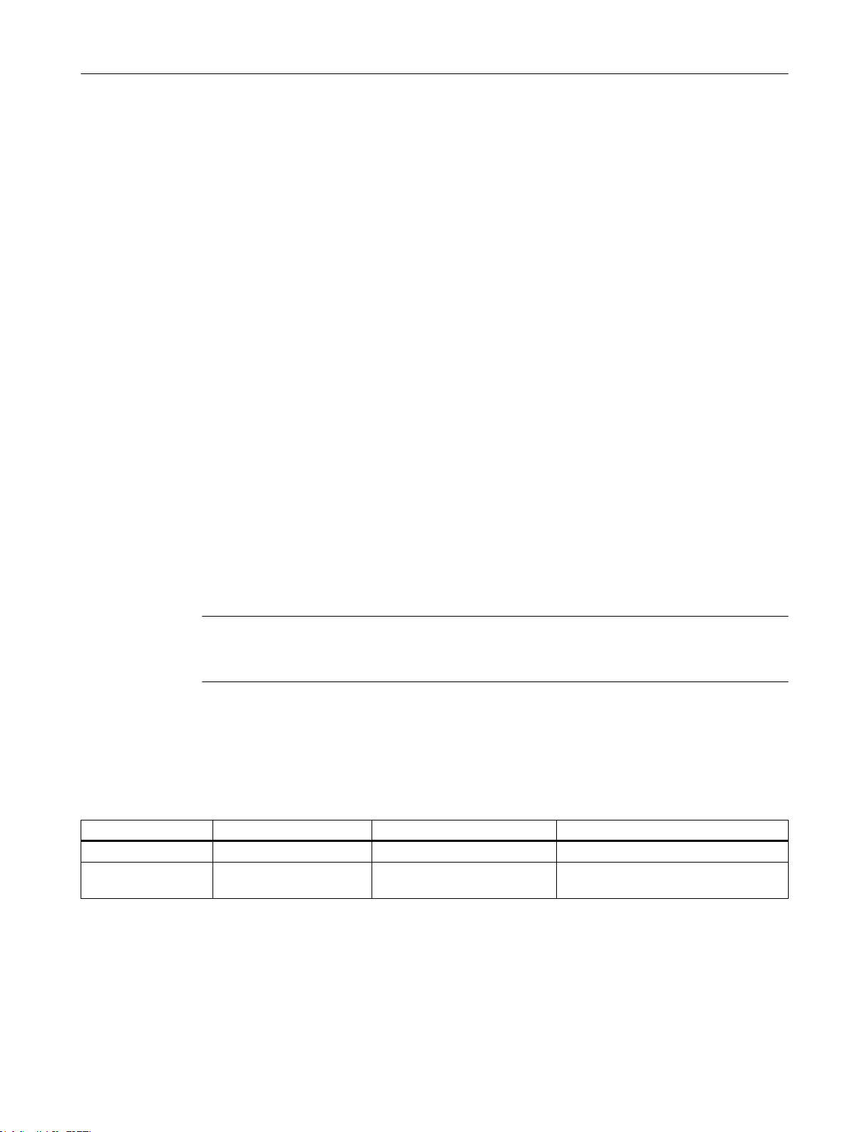
Application example
4.3 Variables used in application example
The current "Parameter handling" state can be read in the symbol browser as follows:
● myCheckbacks.actCommand = READ_PARA_ACTIVE
Read individual parameter activated
● myCheckbacks.actCommand = WRITE_PARA_ACTIVE
Write individual parameter activated
● myCheckbacks.actCommand = SAVE_PARAMETER_ACTIVE
Save all parameters of the POSMO A activated
● myCheckbacks.actCommand = NO_COMMAND_ACTIVE
myCheckbacks.done = TRUE
Parameter handling completed without error
Acknowledging faults on POSMO A
Faults on POSMO A are acknowledged as follows:
● myCommand = RESET_ERRORS
The current fault acknowledgement state can be read in the symbol browser as follows:
● myCheckbacks.actCommand = RESET_ERRORS_ACTIVE
Fault acknowledgement active
● myCheckbacks.actCommand = NO_COMMAND_ACTIVE
myCheckbacks.done = TRUE
Fault acknowledgement completed
Note
A POSMO A fault can only be acknowledged successfully when the cause of the error no
longer exists.
4.3 Variables used in application example
Table 4-1 Overview of the variables used
Symbol Data type Initial value Meaning
myCommand enumCommands NO_COMMAND Command interface
myCheckbacks Struct_Checkbacks NO_COMMAND_ACTIVE Command status
Additional information
Supplement to SIMODRIVE POSMO A Positioning Motor
Function Manual, 01/2015 47
Page 48
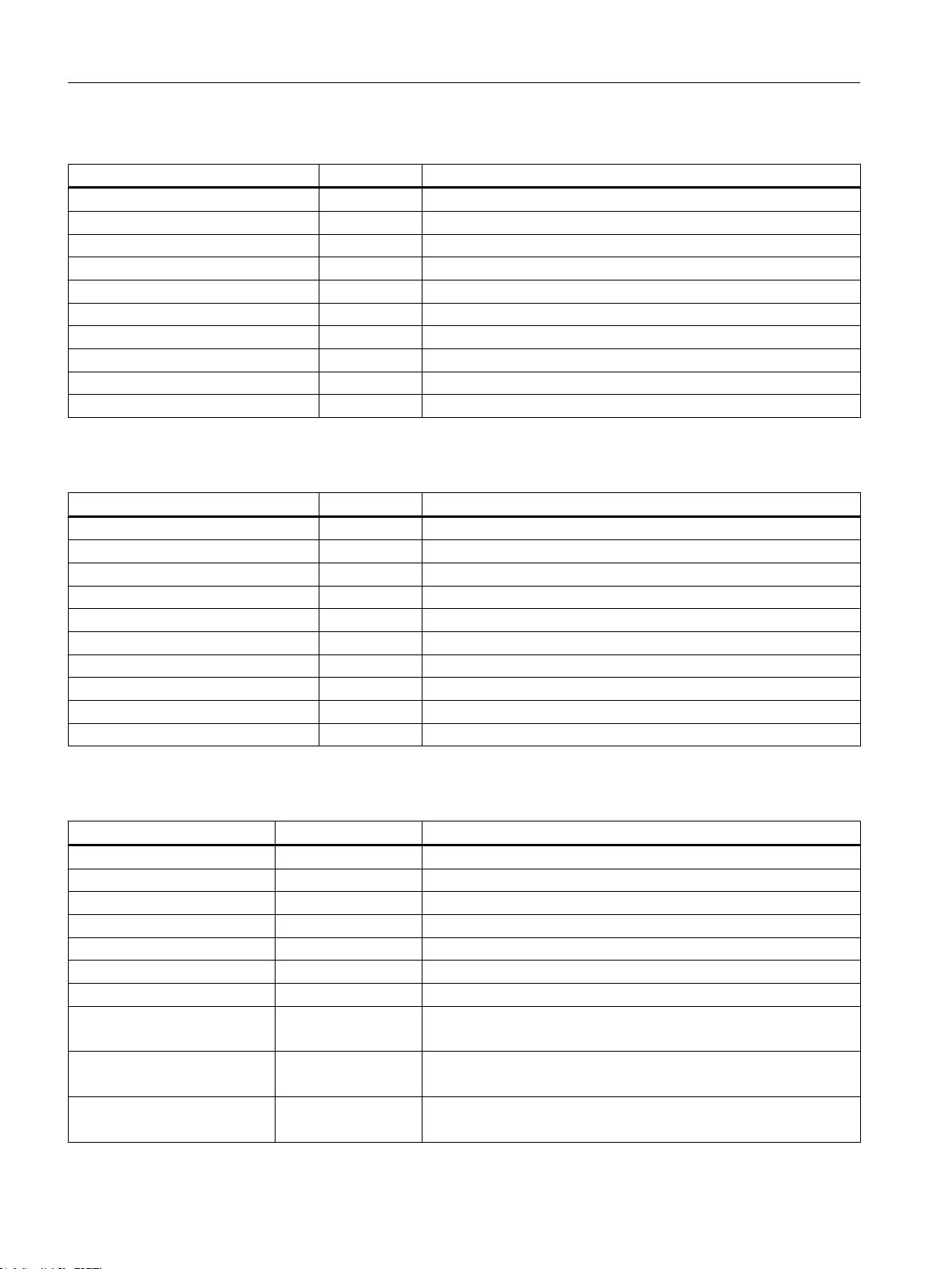
Application example
4.3 Variables used in application example
Table 4-2 Overview of the enums enumCommands
Symbol Enum Value Meaning
START_HOMING 0 Start homing of POSMO A
START_JOG_NEGATIVE 1 Start jogging in negative direction
START_JOG_POSITIVE 2 Start jogging in positive direction
START_MDI_BLOCK_ABSOLUTE 3 Start moving MDI block absolute
STOP 4 Stop all actions
RESET_ERRORS 5 Acknowledge faults on POSMO A
READ_ONE_PARAMETER 6 Start reading individual parameter
WRITE_ONE_PARAMETER 7 Start writing individual parameter
SAVE_PARAMETER 8 Save all parameters in the EEPROM of POSMO A
NO_COMMAND 9 No action to be carried out
Table 4-3 Overview of the enums enumActCommand
Symbol Enum Value Meaning
HOMING_ACTIVE 0 Homing of POSMO A activated
JOG_NEGATIVE_ACTIVE 1 Jogging in negative direction activated
JOG_POSITIVE_ACTIVE 2 Jogging in positive direction activated
MDI_BLOCK_ACTIVE 3 Moving MDI block absolute activated
STOP_ACTIVE 4 Stop all actions activated
RESET_ERRORS_ACTIVE 5 Acknowledge faults on POSMO A active
READ_PARA_ACTIVE 6 Read individual parameter active
WRITE_PARA_ACTIVE 7 Write individual parameter active
SAVE_PARAMETER_ACTIVE 8 Save all parameters in the EEPROM of POSMO A active
NO_COMMAND_ACTIVE 9 No action active
Table 4-4 Data structure Struct_checkbacks
Symbol Data type Meaning
actCommand enumActCommand Enums active actions
done BOOL Action completed
driveReady BOOL Drive (POSMO A) ready for operation
jogPositiveBusy BOOL Jogging positive active
jogNegativeBusy BOOL Jogging negative active
actPosition REAL Current actual position of POSMO A
positionReached BOOL Position when moving MDI block absolute reached
error BOOL Error has occurred
(request canceled; a POSMO A error is pending)
ctrlErrorID WORD Error specification of the _POSMOA_control block.
Number of the parameter assignment error signaled by POSMO A
driveErrorID WORD Error specification of the POSMO A
Reason for an error signaled by POSMO A
Supplement to SIMODRIVE POSMO A Positioning Motor
48 Function Manual, 01/2015
Page 49
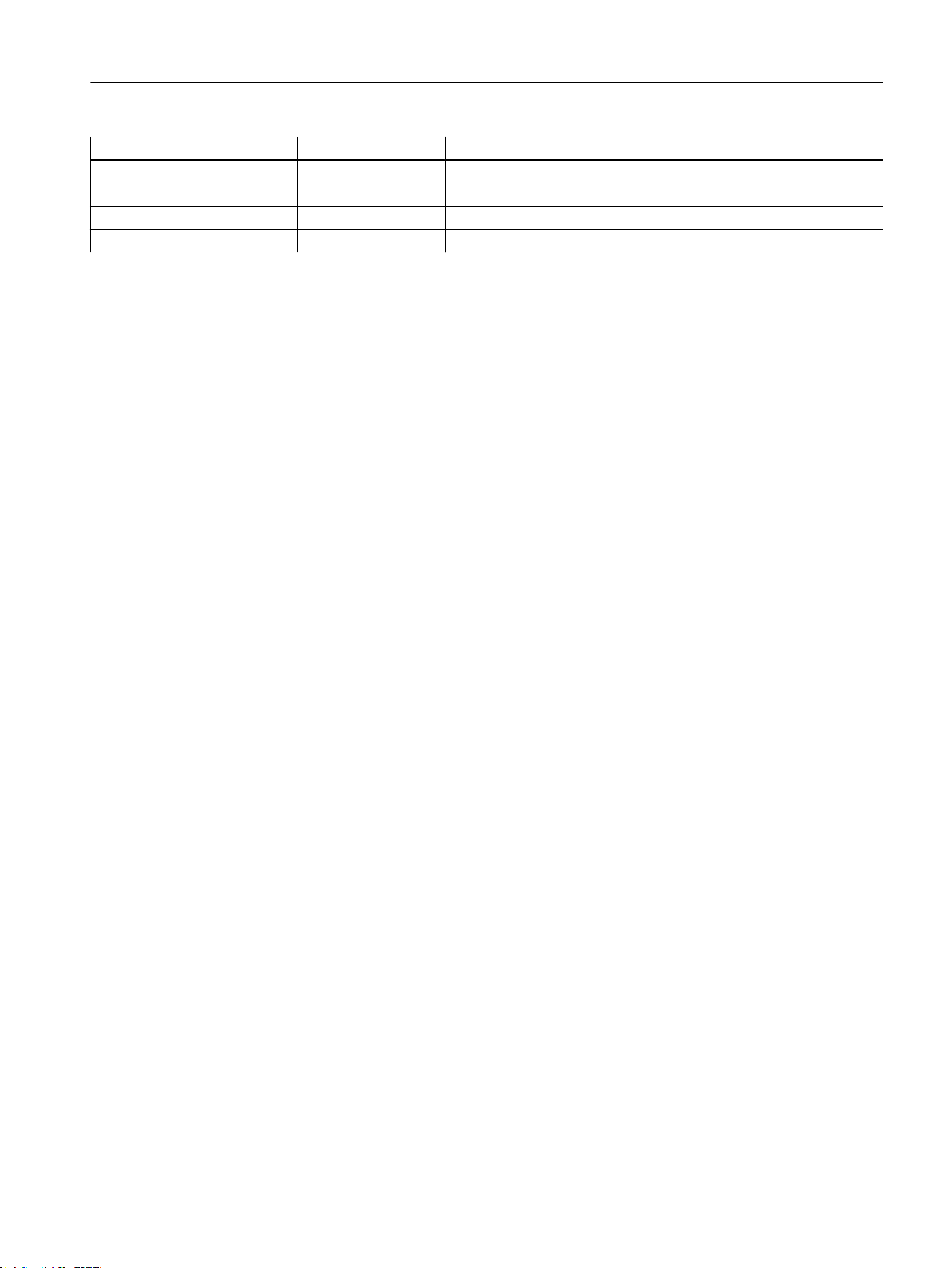
Application example
4.3 Variables used in application example
Symbol Data type Meaning
rwErrorID WORD Error specification of the _POSMOA_rwParameter block.
Error during reading or writing has occurred
driveWarning BOOL POSMO A warning is pending
driveWarningID WORD Warning number
Supplement to SIMODRIVE POSMO A Positioning Motor
Function Manual, 01/2015 49
Page 50

Application example
4.3 Variables used in application example
Supplement to SIMODRIVE POSMO A Positioning Motor
50 Function Manual, 01/2015
Page 51
Appendix
A.1 SIMOTION and SIMATIC names
The table below contains a comparison of SIMOTION and SIMATIC names.
Table A-1 SIMOTION and SIMATIC names for SIMODRIVE POSMO A
A
Name in the SIMOTION system as of
V4.1
(command library in SCOUT)
Function block parameters
_POSMOA_control FB 10 _FB_posmoA_control
pkwIn I_O_address PKWInputInterface
pzdIn I_O_address PZDInputInterface
enable Initialization initialize
homing Referencing homing
releaseBrake Brake_release jog1 Jogging_1 jog1
jog2 Jogging_2 jog2
jogOverride Jogging_override jogOverride
start Start start
singleBlock Automatic_operation enableRdIn Read_in_enable extBlockChange External_blockchange noStopIntermediate No_intermediate_stop intermediateStop
noStop No_stop stop
resetError Fault_acknowledgement resetError
blockNumber Block_number blockNumber
veloOverride Override velocityOverride
setStartInformation Start_byte setStartInformation
mdiMode MDI_type MDIMode
mdiVelocity MDI_velocity MDIVelocity
mdiAcceleration MDI_acceleration MDIAcceleration
mdiPosition MDI_position MDIPosition
reqControl Ctrl_Req pkwOut I_O_address PKWOutputInterface
pzdOut I_O_address PZDOutputInterface
busy FB_coordination busy
ready Ready ready
active - dataReady Data_transfer_ready statusWord Status_word statusWord
Name in the SIMATIC system Name in the SIMOTION system up to V3.2
(SIMOTION function library)
Supplement to SIMODRIVE POSMO A Positioning Motor
Function Manual, 01/2015 51
Page 52
Appendix
A.1 SIMOTION and SIMATIC names
Name in the SIMOTION system as of
V4.1
(command library in SCOUT)
actBlockNumber Actual_block actualBlockNumber
statusInformation Checkback_signal_byte statusInformation
driveWarning Warning driveWarning
driveWarnId Warn_number driveWarningNumber
driveWarnInfo Warn_info driveError - driveError
driveErrorId - driveErrorNumber
error Fault error
errorID Fault_number errorNumber
_POSMOA_nControl FB 9 enable - pkwIn - pzdIn - init Initialization releaseBrake Brake_release accelTime Acc_Time releaseRamp Ramp_en startRamp Ramp_on setpoint Sp releaseSetpoint Sp_en resetError Fault_acknowledgement reqControl Ctrl_req busy FB_coordination pkwOut - pzdOut - ready Ready active - dataReady Data_transfer_ready statusWord Status_word actValue Pv error - errorID - driveError Fault driveErrorId Fault_number driveWarning Warning driveWarnId Warn_number driveWarnInfo Warn_info
_POSMOA_rwParameter FB 11 _FB_posmoA_readWriteParameter
pkwIn I_O_address PKWInputInterface
Name in the SIMATIC system Name in the SIMOTION system up to V3.2
(SIMOTION function library)
Supplement to SIMODRIVE POSMO A Positioning Motor
52 Function Manual, 01/2015
Page 53
Appendix
A.1 SIMOTION and SIMATIC names
Name in the SIMOTION system as of
V4.1
(command library in SCOUT)
paraNumber Number parameterNumber
subindex Index subindex
enableRead Read read
execWrite Write write
setDefault Factory_default setFactorySettings
saveParameter Parameter_save saveParameter
pkwOut I_O_address PKWOutputInterface
busy FB_coordination busy
realValue Value REALValue
dintValue Value DINTValue
done Task_completed done
error Fault_present error
errorID Fault_number errorNumber
_POSMOA_rwAllParameter FB 12 _FB_posmoA_readWriteAllParameter
pkwIn I_O_address PKWInputInterface
execRead Read_all read
execWrite Write_all write
posMode Pos_en pkwOut I_O_address PKWOutputInterface
allParaPosmoA - allPosmoAParameter
busy FB_active busy
done Task_complete done
error Fault_present error
errorID Fault_number errorNumber
errorParaNumber Fault_parameter_number errorParameterNumber
Data structure elements
Struct_POSMOA_params Struct_posmoA_parameter
p1 p1 parameter1
p2 p2 parameter2
p3 p3 parameter3
p4 p4 parameter4
p5 p5 parameter5
p6 p6 parameter6
p7 p7 parameter7
p8 p8 parameter8
p9 p9 parameter9
p10 p10 parameter10
p11 p11 parameter11
p12 p12 parameter12
Name in the SIMATIC system Name in the SIMOTION system up to V3.2
(SIMOTION function library)
Supplement to SIMODRIVE POSMO A Positioning Motor
Function Manual, 01/2015 53
Page 54

Appendix
A.1 SIMOTION and SIMATIC names
Name in the SIMOTION system as of
V4.1
(command library in SCOUT)
p13 p13 parameter13
p14 p14 parameter14
p15 p15 parameter15
p16 p16 parameter16
p17 p17 parameter17
p18 p18 parameter18
p19 p19 parameter19
p20 p20 parameter20
p21 p21 parameter21
p22 p22 parameter22
p23 p23 parameter23
p24 p24 parameter24
p25 p25 parameter25
p26 p26 parameter26
p27 p27 parameter27
p28 p28 parameter28
p29 p29 parameter29
p30 p30 parameter30
p31 p31 parameter31
p32 p32 parameter32
p33 p33 parameter33
p34 p34 parameter34
p35 p35 parameter35
p36 p36 parameter36
p37 p37 parameter37
p38 p38 parameter38
p39 p39 parameter39
p40 p40 parameter40
p41 p41 parameter41
p42 p42 parameter42
p43 p43 parameter43
p44 p44 parameter44
p45 p45 parameter45
p46 p46 parameter46
p47 p47 parameter47
p48 p48 parameter48
p49 p49 parameter49
p50 p50 parameter50
p51 p51 parameter51
p52 p52 parameter52
p53 p53 parameter53
Name in the SIMATIC system Name in the SIMOTION system up to V3.2
(SIMOTION function library)
Supplement to SIMODRIVE POSMO A Positioning Motor
54 Function Manual, 01/2015
Page 55
Appendix
A.2 List of abbreviations
Name in the SIMOTION system as of
V4.1
(command library in SCOUT)
p54 p54 parameter54
p55 p55 parameter55
p56 p56 parameter56
p57 p57 parameter57
p58 p58 parameter58
p59 p59 parameter59
p60 p60 parameter60
p61 p61 parameter61
p62 p62 parameter62
p80 p80 parameter80
p81 p81 parameter81
p82 p82 parameter82
p83 p83 parameter83
p84 p84 parameter84
p85 p85 parameter85
p86 p86 parameter86
p87 p87 parameter87
p99 p99 parameter99
p100 p100 parameter100
p101 p101 parameter101
p700 p700 p701 p701 p880 p880 p930 p930 parameter930
p964 p964 parameter964
p1426 p1426 p1427 p1427 -
Program control word
Array_POSMOA_prgCtrlInfo Array_posmoA_programControlInformation
Name in the SIMATIC system Name in the SIMOTION system up to V3.2
(SIMOTION function library)
A.2 List of abbreviations
Table A-2 Abbreviations
Abbreviation Meaning
DC Direct current
DP Distributed I/O
EEPROM Electrically Erasable Programmable Read-Only Memory
ES SIMOTION SCOUT
Supplement to SIMODRIVE POSMO A Positioning Motor
Function Manual, 01/2015 55
Page 56

Appendix
A.2 List of abbreviations
Abbreviation Meaning
FB Function block
FW Firmware
HW Hardware
IN Input parameters
IN/OUT In/out parameter
LAD Ladder diagram
MDI Manual Data Input
OUT Output parameters
PIV Parameter identification value: Parameter part of a PPO
POSMO A Positioning Motor Actuator
PPO Parameter Process data Object: Cyclic data message frame when transferring data
PZD Process data: Process data part of a PPO
ST Structured text
STW Control word
SW Software
TO Technology object
with PROFIBUS DP and the "variable-speed drives" profile
Supplement to SIMODRIVE POSMO A Positioning Motor
56 Function Manual, 01/2015
Page 57

Index
C
Calling function blocks
POSMO A, 38
D
Data structure of Struct_POSMOA_params, 34
I
I/O variable
Creating, 14
Installation and startup, 11
Integrating the function blocks, 13
M
Message frame substitution
FB _POSMOA_control, 22
FB _POSMOA_nControl, 27
P
POSMO A application example, 41
POSMO A function blocks
_POSMOA_control, 17
_POSMOA_nControl, 24
_POSMOA_rwAllParameter, 32
_POSMOA_rwParameter, 29
Call example, 38
Overview, 17
R
References, 3
S
SIMOTION and SIMATIC names, 51
Supplement to SIMODRIVE POSMO A Positioning Motor
Function Manual, 01/2015 57
Page 58

Index
Supplement to SIMODRIVE POSMO A Positioning Motor
58 Function Manual, 01/2015
 Loading...