

Siemens SIMOCODE pro C, SIMOCODE pro V PB, SIMOCODE pro V MR, SIMOCODE pro S, SIMOCODE pro V EIP System Manual
Page 1
Industrial Controls
Motor management and
control devices
SIMOCODE pro
System Manual
05/2019
A5E40507475002A/RS
Introduction
1
Advantages/benefits/configuration
with SIMOCODE pro
2
Areas of application
3
Features
4
Overview of functions
5
Check list for selecting a device
series
6
An overview of system components
7
Description of system components
8
Compartment identification
9
Accessories
10
3UF50 compatibility mode
11
Mounting, wiring, connecting, system
interfaces, configuration guidelines
12
Commissioning, service,
troubleshooting
13
Safety and commissioning
information for Ex areas
14
Technical data
15
CAx data, dimension drawings
16
List of abbreviations
A
SIMOCODE pro
-AD/004
Page 2
Siemens AG
Smart Infrastructure
Control Products
Postfach 2355
90713 FUERTH
GERMANY
Copyright © Siemens AG 2017.
All rights reserved
Legal information
DANGER
indicates that death or severe personal injury will result if proper precautions are not taken.
WARNING
indicates that death or severe personal injury may result if proper precautions are not taken.
CAUTION
indicates that minor personal injury can result if proper precautions are not taken.
NOTICE
indicates that property damage can result if proper precautions are not taken.
WARNING
Siemens products may only be used for the applications described in the catalog and in the relevant technical
ambient conditions must be complied with. The information in the relevant documentation must be observed.
Warning notice system
This manual contains notices you have to observe in order to ensure your personal safety, as well as to prevent
damage to property. The notices referring to your personal safety are highlighted in the manual by a safety alert
symbol, notices referring only to property damage have no safety alert symbol. These notices shown below are
graded according to the degree of danger.
If more than one degree of danger is present, the warning notice representing the highest degree of danger will
be used. A notice warning of injury to persons with a safety alert symbol may also include a warning relating to
property damage.
Qualified Personnel
The product/system described in this documentation may be operated only by personnel qualified for the specific
task in accordance with the relevant documentation, in particular its warning notices and safety instructions.
Qualified personnel are those who, based on their training and experience, are capable of identifying risks and
avoiding potential hazards when working with these products/systems.
Proper use of Siemens products
Note the following:
documentation. If products and components from other manufacturers are used, these must be recommended
or approved by Siemens. Proper transport, storage, installation, assembly, commissioning, operation and
maintenance are required to ensure that the products operate safely and without any problems. The permissible
Trademarks
All names identified by ® are registered trademarks of Siemens AG. The remaining trademarks in this publication
may be trademarks whose use by third parties for their own purposes could violate the rights of the owner.
Disclaimer of Liability
We have reviewed the contents of this publication to ensure consistency with the hardware and software
described. Since variance cannot be precluded entirely, we cannot guarantee full consistency. However, the
information in this publication is reviewed regularly and any necessary corrections are included in subsequent
editions.
Ⓟ 05/2019 Subject to change
Page 3

Table of contents
1 Introduction ............................................................................................................................................. 9
1.1 Important notes ......................................................................................................................... 9
1.2 Siemens Industry Online Support ........................................................................................... 12
1.3 Siemens Industry Online Support app .................................................................................... 14
1.4 Support Request ..................................................................................................................... 15
1.5 Security information ................................................................................................................ 16
1.6 Current information about operational safety ......................................................................... 17
1.7 Information about third-party software .................................................................................... 18
1.8 Recycling and disposal ........................................................................................................... 22
1.9 What is SIMOCODE pro? ....................................................................................................... 23
1.10 Device series .......................................................................................................................... 24
1.11 Modules, interfaces, configuration options ............................................................................. 26
2 Advantages/benefits/configuration with SIMOCODE pro ........................................................................ 29
2.1 Advantages/benefits ............................................................................................................... 29
2.2 Independent operation ............................................................................................................ 32
2.3 Simplifying configuration with SIMOCODE pro ...................................................................... 33
2.4 Typical configuration ............................................................................................................... 35
3 Areas of application .............................................................................................................................. 39
4 Features ............................................................................................................................................... 41
5 Overview of functions ............................................................................................................................ 47
5.1 Protection functions ................................................................................................................ 47
5.2 Monitoring functions ................................................................................................................ 49
5.3 Safety-oriented tripping ........................................................................................................... 52
5.4 Control functions ..................................................................................................................... 53
5.5 Communication ....................................................................................................................... 54
5.6 Standard functions .................................................................................................................. 57
5.7 Freely-programmable logic modules ...................................................................................... 58
5.8 Operating, service and diagnostics data................................................................................. 59
6 Check list for selecting a device series .................................................................................................. 61
7 An overview of system components ...................................................................................................... 65
SIMOCODE pro
System Manual, 05/2019, A5E40507475002A/RS-AD/004
3
Page 4

Table of contents
8 Description of system components ........................................................................................................ 81
8.1 Basic units (BU) ..................................................................................................................... 81
8.2 Operator panel (OP) .............................................................................................................. 85
8.3 Operator panel with display ................................................................................................... 88
8.3.1 Description of the operator panel with display ....................................................................... 88
8.3.2 Operator controls and display elements of the operator panel with display .......................... 92
8.3.3 Menu of the operator panel with display ................................................................................ 94
8.3.3.1 Timing charts .......................................................................................................................... 94
8.3.3.2 Displays of the operator panel with display ......................................................................... 109
8.3.3.3 Read and adapt main display .............................................................................................. 112
8.3.3.4 Display of measured values in the measured values display .............................................. 115
8.3.3.5 Motor protection and motor control status ........................................................................... 117
8.3.3.6 Display of statistical and maintenance-relevant information on the
statistics/maintenance display ............................................................................................. 119
8.3.3.7 Status display for fieldbus communication ........................................................................... 120
8.3.3.8 Displays the current status of all device I/Os ....................................................................... 122
8.3.3.9 Parameters ........................................................................................................................... 124
8.3.3.10 Adapt display settings .......................................................................................................... 126
8.3.3.11 Resetting, testing and parameterizing via commands ......................................................... 129
8.3.3.12 Displaying all pending messages ......................................................................................... 130
8.3.3.13 Displaying all pending warnings........................................................................................... 130
8.3.3.14 Displaying all pending faults ................................................................................................ 130
8.3.3.15 Reading the device's internal error buffer ............................................................................ 130
8.3.3.16 Reading the device's internal event memory ....................................................................... 131
8.3.3.17 Identification of the motor feeder and the SIMOCODE pro components............................. 132
8.4 Current measuring modules (IM) for the SIMOCODE pro C, SIMOCODE pro S, and
SIMOCODE pro V device series .......................................................................................... 133
8.5 Current / voltage measuring modules (UM, UM+) for the SIMOCODE pro V
High Performance device series ..........................................................................................
6 Decoupling module (DCM) for 1st generation current/voltage measuring modules
8.
135
(e.g. 3UF711.1AA000) ......................................................................................................... 142
8.7 Spectrum of the expansion modules ................................................................................... 146
8.8 Digital module (DM) ............................................................................................................. 147
8.9 Fail-safe digital module (DM-F) ............................................................................................ 148
8.10 Analog module (AM) ............................................................................................................ 151
8.11 Ground-fault module (EM) ................................................................................................... 152
8.12 Temperature module (TM) ................................................................................................... 153
8.13 Multifunction module ............................................................................................................ 154
8.14 Configuration information for SIMOCODE pro V when using an older basic unit ............... 155
8.15 Configuration notes for use of a SIMOCODE pro V MR and SIMOCODE pro V EIP
basic unit .............................................................................................................................. 158
SIMOCODE pro
4 System Manual, 05/2019, A5E40507475002A/RS-AD/004
Page 5

Table of contents
9 Compartment identification .................................................................................................................. 159
9.1 Applications and advantages of compartment identification ................................................ 159
9.2 Hardware and software requirements for compartment identification .................................. 162
9.3 Operating compartment identification ................................................................................... 163
9.4 Mounting, wiring, interfaces, compartment identification ...................................................... 167
9.5 Commissioning and service compartment identification ....................................................... 170
9.6 Alarm, fault, and system events for compartment identification ........................................... 171
9.7 Compartment identification dimension drawings .................................................................. 172
9.8 Technical data compartment identification ........................................................................... 173
10 Accessories ........................................................................................................................................ 175
11 3UF50 compatibility mode ................................................................................................................... 179
11.1 Application, Win-SIMOCODE-DP converter ......................................................................... 179
11.2 Diagram of send and receive data ........................................................................................ 180
11.3 Diagram of diagnostics data ................................................................................................. 181
12 Mounting, wiring, connecting, system interfaces, configuration guidelines............................................ 185
12.1 Mounting ............................................................................................................................... 185
12.1.1 Mounting basic units, expansion modules, and the decoupling module .............................. 185
12.1.2 Mounting the bus terminal .................................................................................................... 188
12.1.3 Mounting of digital modules DM-F Local and DM-F PROFIsafe .......................................... 189
12.1.4 Mounting of current measuring modules .............................................................................. 189
12.1.5 Mounting the current / voltage measuring modules .............................................................. 191
12.1.6 Mounting of the operator panel and operator panel with display .......................................... 193
12.2 Wiring, connecting ................................................................................................................ 195
12.2.1 Wiring basic units, expansion modules and the decoupling module .................................... 195
12.2.2 Wiring digital modules DM-F Local and DM-F PROFIsafe ................................................... 221
12.2.3 Wiring of current measuring modules ................................................................................... 226
12.2.4 Wiring of current / voltage measuring modules .................................................................... 228
12.2.5 Measuring current with an external current transformer (interposing transformer) .............. 233
12.3 System interfaces ................................................................................................................. 236
12.3.1 Information about the system interfaces ............................................................................... 236
12.3.2 System interfaces on basic units, expansion modules, decoupling module, current
measuring modules and current / voltage measuring modules ............................................ 237
12.3.3 System interfaces on the digital modules DM-F Local and DM-F PROFIsafe ..................... 242
12.3.4 System interfaces on the operator panel and the operator panel with display ..................... 243
12.3.5 Closing the system interfaces with the system interface cover ............................................ 247
12.3.6 PROFIBUS DP to a 9-pole SUB-D socket ............................................................................ 248
12.3.7 Ethernet cable to RJ45 socket (PROFINET and EtherNet/IP) ............................................. 249
12.3.8 Modbus RTU connection to the SIMOCODE pro device ...................................................... 250
12.4 Configuration guidelines ....................................................................................................... 252
12.4.1 Configuration guidelines on PROFIBUS DP .........................................................................
4.2 Configuration guidelines on PROFINET ............................................................................... 254
12.
SIMOCODE pro
System Manual, 05/2019, A5E40507475002A/RS-AD/004
252
5
Page 6

Table of contents
13 Commissioning, service, troubleshooting.............................................................................................. 255
13.1 General information about commissioning and service ....................................................... 255
13.2 Commissioning..................................................................................................................... 257
13.2.1 Commissioning with PROFIBUS .......................................................................................... 257
13.2.1.1 PROFIBUS commissioning steps ........................................................................................ 257
13.2.1.2 Setting the PROFIBUS DP address..................................................................................... 258
13.2.1.3 Diagnostics via LED display on the basic unit and on the operator panel (PROFIBUS) ..... 259
13.2.1.4 Diagnostics via LED display on the modules DM-F Local or DM-F PROFIsafe .................. 259
13.2.2 Commissioning with PROFINET .......................................................................................... 260
13.2.2.1 PROFINET commissioning steps ........................................................................................ 260
13.2.2.2 Setting IP parameters and PROFINET device name .......................................................... 261
13.2.2.3 Setting the time manually after switch-on or recovery of the supply voltage ....................... 263
13.2.2.4 Diagnostics via LED display on the basic unit and on the operator panel (PROFINET) ..... 264
13.2.3 Commissioning with Modbus ............................................................................................... 265
13.2.3.1 Commissioning with Modbus RTU ....................................................................................... 265
13.2.4 Commissioning with EtherNet/IP ......................................................................................... 270
13.2.4.1 EtherNet/IP commissioning steps ........................................................................................ 270
13.2.4.2 Setting IP parameters and EIP device name ....................................................................... 271
13.2.4.3 Set the time manually after switch-on or recovery of the supply voltage ............................. 273
13.2.4.4 Diagnostics via LED display on the basic unit and on the operator panel with
EtherNet/IP ........................................................................................................................... 274
13.3 Service ................................................................................................................................. 275
13.3.1 Preventive maintenance ...................................................................................................... 275
13.3.2 Backing up and saving parameters...................................................................................... 277
13.3.3 Replacing SIMOCODE pro components ............................................................................. 279
13.3.4 Exchanging a 3UF52 operator panel for a 3UF720 operator panel .....................................
13.
3.5 Restoring factory settings .................................................................................................... 285
283
13.3.6 Firmware update of device components .............................................................................. 286
13.3.7 Support Request .................................................................................................................. 287
13.4 Troubleshooting ................................................................................................................... 288
13.4.1 Error buffer ........................................................................................................................... 288
13.4.2 Event memory ...................................................................................................................... 290
13.4.3 Alarms, faults, and system events - error handling .............................................................. 291
14 Safety and commissioning information for Ex areas ............................................................................. 303
14.1 Motor protection functions (overload protection, thermistor protection) .............................. 303
14.1.1 Module integration ............................................................................................................... 303
14.1.2 Information and standards ................................................................................................... 304
14.1.3 Installation and commissioning – motor protection functions (overload protection,
thermistor protection) ........................................................................................................... 305
14.1.3.1 Operating Instructions .......................................................................................................... 305
14.1.3.2 Setting the rated motor current ............................................................................................ 305
14.1.3.3 SIMOCODE pro with thermistor input .................................................................................. 307
14.1.3.4 Sensor circuit wiring ............................................................................................................. 308
14.1.3.5 Short-circuit protection for type of coordination 2 according to IEC 60947-4-1 ................... 309
14.1.3.6 Cable protection ................................................................................................................... 309
14.1.3.7 Test ...................................................................................................................................... 309
14.1.3.8 Further safety guidelines ...................................................................................................... 311
14.1.3.9 Ambient conditions ............................................................................................................... 311
14.1.3.10 Safety values ........................................................................................................................ 312
SIMOCODE pro
6 System Manual, 05/2019, A5E40507475002A/RS-AD/004
Page 7

Table of contents
14.1.4 Maintenance and repairs ...................................................................................................... 312
14.1.5 Warranty ............................................................................................................................... 312
14.1.6 Further information ................................................................................................................ 313
14.2 Dry-running protection for centrifugal pumps by active power monitoring ........................... 314
14.2.1 Module integration ................................................................................................................ 314
14.2.2 Information and standards .................................................................................................... 314
14.2.3 Installation and commissioning – dry-running protection for centrifugal pumps by
means of active power monitoring ........................................................................................ 318
14.2.3.1 Operating Instructions ........................................................................................................... 318
14.2.3.2 General information on installation and commissioning ....................................................... 318
14.2.3.3 Special conditions for commissioning and operation ............................................................ 319
14.2.3.4 Setting the parameters.......................................................................................................... 320
14.2.3.5 Line protection ...................................................................................................................... 322
14.2.3.6 Test ....................................................................................................................................... 322
14.2.3.7 Further safety information ..................................................................................................... 325
14.2.3.8 Environmental conditions ...................................................................................................... 325
14.2.3.9 Safety values ........................................................................................................................ 326
14.2.4 Periodic tests ........................................................................................................................ 326
14.2.5 Maintenance and repair ........................................................................................................ 326
14.2.6 Warranty ............................................................................................................................... 327
14.2.7 More information ................................................................................................................... 327
15 Technical data .................................................................................................................................... 329
15.1 Common technical data ........................................................................................................ 329
15.2 Technical specifications of the SIMOCODE pro C / pro S / pro V PB /
pro V MR basic units ............................................................................................................. 332
15.3 Technical specifications of the SIMOCODE pro V PN / pro V PN GP /
pro V EIP basic units............................................................................................................. 337
15.4 Technical data of the current measuring modules and the current / voltage measuring
modules ................................................................................................................................ 340
15.5 Technical data of the decoupling module ............................................................................. 345
15.6 Technical data of the expansion modules ............................................................................ 346
15.6.1 Technical data of the digital modules ................................................................................... 346
15.6.2 Technical data, digital modules DM-F Local and DM-F PROFIsafe ..................................... 347
15.6.3 Technical data of the DM-F Local digital module ................................................................. 349
15.6.4 Technical data of the DM-F-PROFIsafe digital module ........................................................ 351
15.6.5 Safety-related technical data of the digital modules DM-F Local and DM-F PROFIsafe ..... 352
15.6.6 Technical data of the analog module .................................................................................... 352
15.6.7 Technical data of the ground-fault module 3UF7500-1AA00-0 ............................................ 354
15.6.8 Technical data of the ground-fault module 3UF7510-1AA00-0 ............................................ 355
15.6.9 Technical data of the temperature module ........................................................................... 356
15.7 Technical data of the multifunction module .......................................................................... 357
15.8 Technical data of the operator panels .................................................................................. 360
15.8.1 Technical data of the operator panel .................................................................................... 360
15.8.2 Technical data of the operator panel with display ................................................................ 361
15.9 Technical data of the compartment identification ................................................................. 363
SIMOCODE pro
System Manual, 05/2019, A5E40507475002A/RS-AD/004
7
Page 8

Table of contents
15.10 Short-circuit protection with fuses for motor feeders for short-circuit currents up to
100 kA and 690 V for 1st generation current / voltage measuring module ......................... 364
15.11 Typical reaction times .......................................................................................................... 365
15.11.1 Typical reaction times of the SIMOCODE pro C/V device series ........................................ 365
15.11.2 Typical response times of SIMOCODE pro S device series ................................................ 366
15.11.3 Typical reaction times of the Modbus RTU device series .................................................... 367
15.12 Technical data in Siemens Industry Online Support ............................................................ 368
16 CAx data, dimension drawings ............................................................................................................. 369
16.1 CAx data .............................................................................................................................. 369
A List of abbreviations ............................................................................................................................. 371
A.1 List of abbreviations ............................................................................................................. 371
Glossary .............................................................................................................................................. 375
Index ................................................................................................................................................... 399
SIMOCODE pro
8 System Manual, 05/2019, A5E40507475002A/RS-AD/004
Page 9

1
1.1 Important notes
Purpose of this manual
The SIMOCODE pro System Manual describes in detail the motor management system and
its functions. It contains information about configuring, commissioning, service and
maintenance.
In addition to help on how to identify and rectify faults in the event of a malfunction, the
manual also contains specific information for servicing and maintenance.
Required basic knowledge
To understand this manual you will require basic knowledge of low-voltage controls and
distribution, digital circuit engineering and automation technology.
Scope of the manual
This manual is applicable to the listed SIMOCODE pro system components. It contains a
description of the components applicable at the time of printing the manual. SIEMENS
reserves the right to include updated information about launched new components or new
versions of components in a Product Information.
Manual Collection
A Manual Collection (https://support.industry.siemens.com/cs/document/109743951), a
collection of the following five SIMOCODE pro manuals, is available in Industry Online
Support:
● SIMOCODE pro - 1 Getting Started
● SIMOCODE pro - 2 System Manual
● SIMOCODE pro - 3 Parameterization
● SIMOCODE pro - 4 Applications
● SIMOCODE pro - 5 Communication.
SIMOCODE pro
System Manual, 05/2019, A5E40507475002A/RS-AD/004
9
Page 10

Introduction
Response
Function 1
Function 2
Function 3
Tripping — X (d)
X
Signaling X X
—
Deactivated X X
X (d)
Delay
0 to 25.5 s (default: 0)
—
—
1.1 Important notes
Device series
When reference is made to "SIMOCODE pro", the reference also includes the following
device series:
SIMOCODE pro C (see Device series (Page 24))
SIMOCODE pro S (see Device series (Page 24))
SIMOCODE pro V PB (PROFIBUS) (see Device series (Page 24))
SIMOCODE pro V PN (PROFINET) (see Device series (Page 24))
SIMOCODE pro V PN GP (PROFINET) (see Device series (Page 24))
SIMOCODE pro V MR (Modbus RTU) (see Device series (Page 24))
SIMOCODE pro V EIP (EtherNet/IP) (see Device series (Page 24))
When reference is made to "SIMOCODE pro V", the reference also includes all pro V
devices, independently of communication.
SIMOCODE pro response tables
Specific responses (deactivated, signaling, warning, tripping) can be parameterized for
various SIMOCODE pro functions, such as overload. These are always displayed in tabular
form:
● "X" = Applicable
● "—" = not applicable
● Default values are marked "d" for "default" in parentheses.
Warning X (d) X —
Short description of the responses:
● Tripping: The contactor controls QE* are tripped. A fault message is generated which is
available as diagnostics via the communication bus. The fault message and the
device-internal signal remain on until the appropriate length of time has elapsed or the
cause of the fault has been eliminated and acknowledged.
SIMOCODE pro
10 System Manual, 05/2019, A5E40507475002A/RS-AD/004
● Warning: In addition to the device-internal signal, a warning signal is generated that is
available as diagnostics via the communication bus.
● Signaling: Only a device-internal signal is generated, which can be further processed as
required.
● Deactivated: The appropriate function is switched off, no signals are generated.
A delay time can also be set for specific responses.
Page 11

Introduction
1.1 Important notes
Operating instructions and other manuals
● Please read the operating instructions of the respective components (Operating
instructions (https://support.industry.siemens.com/cs/ww/en/ps/16027/man
● In addition to the "SIMOCODE pro" manual collection, the following manuals are available
to you:
– The manual "SIMOCODE pro Safety fail-safe digital modules"
(https://support.automation.siemens.com/WW/view/en/50564852
– The appropriate manual for the DP master
– The system manual "SIMATIC PROFINET System Description"
(https://support.automation.siemens.com/WW/view/en/19292127
– The manual "Fault-tolerant S7-400H systems"
(https://support.automation.siemens.com/WW/view/en/1186523
– Programming manual "PROFINET IO - from PROFIBUS DP to PROFINET IO"
(https://support.automation.siemens.com/WW/view/en/19289930
– The application description "Saving Energy with SIMATIC S7 and ET200 S"
(https://support.automation.siemens.com/WW/view/en/41986454
)
))
)
)
)
)
More information
You will find further information on the Internet:
● SIMOCODE pro (https://www.siemens.com/simocode
● Information and Download Center (https://www.siemens.com/sirius/infomaterial)
● Siemens Industry Online Support (SIOS)
● Certificates (https://support.industry.siemens.com/cs/ww/en/ps/16027/cert).
Disclaimer of liability
The products described here have been developed to perform safety-related functions as
part of a complete plant or machine. In general, a complete safety system consists of
sensors, evaluation units, signaling devices and methods for safe tripping. The manufacturer
is responsible for ensuring safe functioning of the complete plant or machine. Siemens AG,
its subsidiaries, and associated companies (hereinafter referred to as "Siemens") are not in a
position to guarantee every characteristic of a complete plant or machine not designed by
Siemens.
Siemens also denies all responsibility for any recommendations that are made or implied in
the following description. No new guarantee, warranty, or liability claims above those
standard to Siemens can be derived from the following description.
(https://support.industry.siemens.com/cs/ww/en/ps
)
)
Recycling and disposal
For environmentally friendly recycling and disposal of your old device, please contact a
company certified for the disposal of electronic waste and dispose of the device in
accordance with the regulations in your country.
SIMOCODE pro
System Manual, 05/2019, A5E40507475002A/RS-AD/004
11
Page 12

Introduction
1.2 Siemens Industry Online Support
1.2 Siemens Industry Online Support
Information and service
At Siemens Industry Online Support you can obtain up-to-date information from our global
support database quickly and simply. To accompany our products and systems, we offer a
wealth of information and services that provide support in every phase of the lifecycle of your
machine or plant – from planning and implementation and commissioning, right through to
maintenance and modernization:
● Product support
● Application examples
● Services
● Forum
● mySupport
Link: Siemens Industry Online Support (https://support.industry.siemens.com/cs/de/en)
Product support
Here you will find all the information and comprehensive know-how for your product:
● FAQs
Our replies to frequently asked questions.
● Manuals/operating instructions
Read online or download, available as PDF or individually configurable.
● Certificates
Clearly sorted according to approving authority, type and country.
● Characteristics
For support in planning and configuring your system.
● Product announcements
The latest information and news concerning our products.
● Downloads
Here you will find updates, service packs, HSPs and much more for your product.
● Application examples
Function blocks, background and system descriptions, performance statements,
demonstration systems, and application examples, clearly explained and represented.
● Technical data
Technical product data for support in planning and implementing your project.
Link: Product support (https://support.industry.siemens.com/cs/ww/en/ps)
SIMOCODE pro
12 System Manual, 05/2019, A5E40507475002A/RS-AD/004
Page 13

Introduction
1.2 Siemens Industry Online Support
mySupport
With "mySupport", your personal work area, you get the very best out of your Industry Online
Support experience. Everything enables you to find the right information - every time.
The following functions are now available:
● Personal Messages
Your personal mailbox for exchanging information and managing your contacts
● Requests
Use our online form for specific solution suggestions, or send your technical inquiry
directly to a specialist in Technical Support
● Notifications
Make sure you always have the latest information - individually tailored to your needs
● Filter
Simple management and re-use of your filter settings from Product Support and the
Technical Forum
● Favorites / Tagging
Create your own knowledge database by assigning "Favorites" and "Tags" to
documents – simply and efficiently
● Entries last viewed
Clear presentation of your last viewed entries
● Documentation
Configure your individual documentation from different manuals – quickly and without
complications
● Personal data
Change personal data and contact information here
● CAx data
Simple access to thousands of items of CAx data such as 3D models, 2D dimension
drawings, EPLAN macros, and much more
SIMOCODE pro
System Manual, 05/2019, A5E40507475002A/RS-AD/004
13
Page 14

Introduction
Link for Android
Link for iOS
Link for Windows Phone
1.3 Siemens Industry Online Support app
1.3 Siemens Industry Online Support app
Siemens Industry Online Support app
You can use the Siemens Industry Online Support app to access all the device-specific
information available on the Siemens Industry Online Support portal for a particular article
number, including operating instructions, manuals, datasheets, FAQs etc.
The Siemens Industry Online Support app is available for iOS, Android or Windows Phone
devices. You can download the app from the following links:
SIMOCODE pro
14 System Manual, 05/2019, A5E40507475002A/RS-AD/004
Page 15

Introduction
Support Request:
Internet (https://support.industry.siemens.com/My/ww/en/requests)
1.4 Support Request
1.4 Support Request
Using the Support Request form in Online Support you can send your query directly to our
Technical Assistance. After describing your query in a few guided steps, you will immediately
be provided with possible suggestions for solving the problem.
SIMOCODE pro
System Manual, 05/2019, A5E40507475002A/RS-AD/004
15
Page 16

Introduction
1.5 Security information
1.5 Security information
Siemens provides products and solutions with industrial security functions that support the
secure operation of plants, systems, machines and networks.
In order to protect plants, systems, machines and networks against cyber threats, it is
necessary to implement – and continuously maintain – a holistic, state-of-the-art industrial
security concept. Siemens’ products and solutions constitute one element of such a concept.
Customers are responsible for preventing unauthorized access to their plants, systems,
machines and networks. Such systems, machines and components should only be
connected to an enterprise network or the internet if and to the extent such a connection is
necessary and only when appropriate security measures (e.g. firewalls and/or network
segmentation) are in place.
For additional information on industrial security measures that may be implemented,
please visit
https://www.siemens.com/industrialsecurity
Siemens’ products and solutions undergo continuous development to make them more
secure. Siemens strongly recommends that product updates are applied as soon as they are
available and that the latest product versions are used. Use of product versions that are no
longer supported, and failure to apply the latest updates may increase customer’s exposure
to cyber threats.
To stay informed about product updates, subscribe to the
Siemens Industrial Security RSS Feed under
https://www.siemens.com/industrialsecurity
SIMOCODE pro
16 System Manual, 05/2019, A5E40507475002A/RS-AD/004
Page 17
Introduction
DANGER
Hazardous Voltage
Can Cause Death, Serious Injury or Risk of Property Damage
Please take note of our latest information!
1.6 Current information about operational safety
1.6 Current information about operational safety
Important note for maintaining operational safety of your system
Systems with safety-related characteristics are subject to special operational safety
requirements on the part of the operator. The supplier is also obliged to comply with special
product monitoring measures. For this reason, we publish a special newsletter containing
information on product developments and features that are (or could be) relevant to
operation of safety-related systems. By subscribing to the appropriate newsletter in the
Industry newsletter system (https://www.industry.siemens.com/newsletter
that you are always up-to-date and able to make changes to your system, when necessary.
Sign on to the following newsletter under "Products & Solutions":
• Control Components and System Engineering News
• Safety Integrated Newsletter.
), you will ensure
SIMOCODE pro
System Manual, 05/2019, A5E40507475002A/RS-AD/004
17
Page 18

Introduction
Support Request:
Internet (https://support.industry.siemens.com/My/ww/en/requests)
1.7 Information about third-party software
1.7 Information about third-party software
Third-party software components
This product, this solution or this service ("product") contains the third-party software
components listed below. These consist either of open source software that is licensed
under a license recognized by Open Source Initiative (http://www.opensource.org
license defined by Siemens as being comparable ("OSS") and/or commercial software or
freeware. With regard to the OSS components, the relevant OSS terms and conditions take
priority over all other terms and conditions applicable to this product.
SIEMENS is providing you with the OSS portions of this product at no additional cost. Insofar
as SIEMENS has combined or linked, according to the definition of the applicable license,
specific components of the product with OSS components that are licensed under
GNU LGPL Version 2 or a later version, and insofar as the applicable object file may not be
used without restrictions ("LGPL-licensed module", whereby the LGPL-licensed module and
the components with which the LGPL-licensed module is combined are hereinafter referred
to as "combined product") and the applicable LGPL license criteria are fulfilled, you may
additionally (i) edit the combined product for your own purposes and may in particular
acquire the right to edit the combined product to link it with a modified version of the LGPLlicensed module and (ii) reverse engineer the combined product, but solely for the purpose
of error correction of your edits. The right to edit shall not include the right to distribute. You
must treat as confidential all information you acquire from reverse engineering of the
combined product.
) or a
Certain OSS licenses require SIEMENS to publish the source code, e.g. the
GNU General Public License, the GNU Lesser General Public License and the
Mozilla Public License. Insofar as these licenses apply and the product has not already been
delivered with the necessary source code, anyone may request a copy of the source code
from Support Request during the period of time specified in the applicable OSS license:
Use the Support Request online form to send your query directly to our Technical Support.
After describing your query in a few guided steps, you will immediately be provided with
possible suggestions for solving the problem.
Subject: open source inquiry (specify the product name and version, where applicable)
SIEMENS can charge a processing fee of up to 5 euros to respond to the inquiry.
SIMOCODE pro
18 System Manual, 05/2019, A5E40507475002A/RS-AD/004
Page 19

Introduction
NOTICE
Open source software and/or third-party software included in this product
Component
Open Source
Software [Yes/No]
Acknowledgements/
Comments
License conditions and copyright notices
COMPONENT TIVA PRODUCTS - 2.1.0 (see below)
1.7 Information about third-party software
Warranty regarding use of open source software
The warranty obligations of SIEMENS are laid down in the applicable contract with
SIEMENS. Insofar as you modify the product or the OSS components or use them in a
manner other than specified by SIEMENS, warranty shall be ruled out and no technical
support shall be provided. The following license terms and conditions may contain liability
limitations that apply between you and the relevant licensor. To clarify matters, your attention
is drawn to the fact that SIEMENS shall not cede any warranty obligations on behalf of or as
an obligation for a third-party licensor.
Please note the following license terms and conditions and copyright notices applicable to
the open source software and/or other components (or parts thereof):
tiva ware - 2.1.0 NO LICENSE AND COPYRIGHT INFORMATION FOR
SIMOCODE pro
System Manual, 05/2019, A5E40507475002A/RS-AD/004
19
Page 20

Introduction
1.7 Information about third-party software
LICENSE CONDITIONS AND COPYRIGHT NOTICES
Commercial Software: tiva ware - 2.1.0
Enclosed you'll find license conditions and copyright notices applicable for Commercial
Software tiva ware - 2.1.0.
License conditions:
//
// Redistribution and use in source and binary forms, with or without
// modification, are permitted provided that the following conditions
// are met:
//
// Redistributions of source code must retain the above copyright
// notice, this list of conditions and the following disclaimer.
//
// Redistributions in binary form must reproduce the above copyright
// notice, this list of conditions and the following disclaimer in the
// documentation and/or other materials provided with the
// distribution.
//
// Neither the name of Texas Instruments Incorporated nor the names of
// its contributors may be used to endorse or promote products derived
// from this software without specific prior written permission.
//
// THIS SOFTWARE IS PROVIDED BY THE COPYRIGHT HOLDERS AND
CONTRIBUTORS
// "AS IS" AND ANY EXPRESS OR IMPLIED WARRANTIES, INCLUDING, BUT NOT
// LIMITED TO, THE IMPLIED WARRANTIES OF MERCHANTABILITY AND FITNESS FOR
// A PARTICULAR PURPOSE ARE DISCLAIMED. IN NO EVENT SHALL THE COPYRIGHT
// OWNER OR CONTRIBUTORS BE LIABLE FOR ANY DIRECT, INDIRECT, INCIDENTAL,
// SPECIAL, EXEMPLARY, OR CONSEQUENTIAL DAMAGES (INCLUDING, BUT NOT
// LIMITED TO, PROCUREMENT OF SUBSTITUTE GOODS OR SERVICES; LOSS OF
USE,
// DATA, OR PROFITS; OR BUSINESS INTERRUPTION) HOWEVER CAUSED AND ON
ANY
// THEORY OF LIABILITY, WHETHER IN CONTRACT, STRICT LIABILITY, OR TORT
// (INCLUDING NEGLIGENCE OR OTHERWISE) ARISING IN ANY WAY OUT OF THE
USE
// OF THIS SOFTWARE, EVEN IF ADVISED OF THE POSSIBILITY OF SUCH DAMAGE.
SIMOCODE pro
20 System Manual, 05/2019, A5E40507475002A/RS-AD/004
Page 21

Introduction
1.7 Information about third-party software
Copyrights:
Copyright © 2013-2014 Texas Instruments Incorporated
Copyright © 2012-2014 Texas Instruments Incorporated
Copyright © 2011-2014 Texas Instruments Incorporated
Copyright © 2010-2014 Texas Instruments Incorporated
Copyright © 2008-2014 Texas Instruments Incorporated
Copyright © 2007-2014 Texas Instruments Incorporated
Copyright © 2006-2014 Texas Instruments Incorporated
Copyright © 2005-2014 Texas Instruments Incorporated
SIMOCODE pro
System Manual, 05/2019, A5E40507475002A/RS-AD/004
21
Page 22

Introduction
1.8 Recycling and disposal
1.8 Recycling and disposal
For environmentally friendly recycling and disposal of your old device, please contact a
company certified for the disposal of old electrical and/or electronic devices and dispose of
the device in accordance with the regulations in your country.
SIMOCODE pro
22 System Manual, 05/2019, A5E40507475002A/RS-AD/004
Page 23

Introduction
1.9 What is SIMOCODE pro?
1.9 What is SIMOCODE pro?
SIMOCODE pro (SIRIUS Motor Management and Control Device) is a flexible and modular
motor management system for motors with constant speeds in low-voltage applications. It
optimizes the link between the control system and the motor feeder, increases plant
availability and allows significant savings to be made during installation, commissioning,
operation and maintenance. SIMOCODE pro is installed in the low-voltage switchgear
system and links the higher-level automation system and the motor feeder intelligently. It
comprises the following functions:
● Multifunctional and electronic full motor protection, independently of the
automation system
● Integrated control functions for motor control (instead of hardware)
● Detailed operating, service and diagnostics data
● Fail-safe shutdown up to SIL3 using fail-safe expansion modules
(High Performance units only)
● Open communication through PROFIBUS DP, PROFINET, Modbus RTU and EtherNet/IP
● Parameterization with the SIMOCODE ES (TIA Portal) software package
Only the switching and short-circuit protection mechanisms of the main circuit
(contactors, circuit breakers, fuses) are additionally needed.
SIMOCODE pro
System Manual, 05/2019, A5E40507475002A/RS-AD/004
23
Page 24

Introduction
1.10 Device series
1.10 Device series
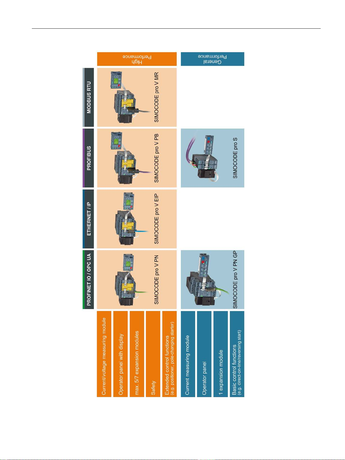
The following functionally graduated device series are available for SIMOCODE pro:
● Basic units:
SIMOCODE pro C - the compact system for PROFIBUS DP communication with a
direct-on-line and reversing starter function and/or for controlling a circuit breaker
(MCCB).
● General Performance units:
– SIMOCODE pro S - the smart system for PROFIBUS DP with direct-on-line, reversing,
and star-delta starter function or for controlling a circuit breaker or soft starter. Its
expandability with a multifunction module ensures there are always plenty of inputs
and outputs. It enables precise ground-fault monitoring via the 3UL23 residual current
transformer and temperature measurement.
– SIMOCODE pro V PN GP - the smart system for PROFINET with direct-on-line,
reversing, and star-delta starter function or for controlling a circuit breaker or soft
starter. Its expandability with an expansion module ensures there are always plenty of
inputs and outputs, precise ground-fault monitoring via the 3UL23 residual current
transformer and temperature measurement.
● High Performance units:
SIMOCODE pro V – the variable system that offers numerous functions, such as voltage
measurement and fail-safe shutdown, in addition to all the SIMOCODE pro C/pro S
functions. Devices are available for the following communication protocols:
– PROFIBUS DP
– Modbus RTU
– PROFINET
– EtherNet/IP.
See Check list for selecting a device series (Page 61).
SIMOCODE pro
24 System Manual, 05/2019, A5E40507475002A/RS-AD/004
Page 25
Introduction
1.10 Device series
Figure 1-1 SIMOCODE pro device series
SIMOCODE pro
System Manual, 05/2019, A5E40507475002A/RS-AD/004
25
Page 26

Introduction
NOTICE
Maximum length of the connecting cable
NOTICE
The maximum distance between modules
1.11 Modules, interfaces, configuration options
1.11 Modules, interfaces, configuration options
For each feeder, every system comprises a basic unit and a separate current measuring
module. Both modules are connected to each other electronically via the system interface,
by means of a connecting cable, and can be installed together as a unit (behind one another)
or separately (side-by-side). An operator panel can also be connected optionally via the
second system interface on the basic unit, and installed in the switchgear cabinet door. The
current measuring module and the operator panel are connected to the basic unit via
connecting cables, which also supply the power. More inputs, outputs and functions can be
added to the SIMOCODE pro S, pro V PB, pro V MR, pro V EtherNet/IP and
pro V PN /pro V PN GP basic units by means of optional expansion modules, thus
supplementing the inputs and outputs already existing on the basic unit. All modules are
connected by connecting cables. The connecting cables are available with different lengths
(ribbon cable 0.025 m, 0.1 m, 0.15 m, 0.3 m, 0.5 m; round cable 0.5 m, 1.0 m, 2.5 m).
The total length of all cables must not exceed 3 m on either of the system interfaces of the
basic unit!
The maximum distance between the modules (e. g. between the basic unit and the current
measuring module) must not exceed 2.5 m.
SIMOCODE pro
26 System Manual, 05/2019, A5E40507475002A/RS-AD/004
Page 27

Introduction
1.11 Modules, interfaces, configuration options
Additional control programs (star-delta starters, Dahlander starters, pole-changing starters,
soft starters, each program also possible in combination with reversing starter, solenoid
valve and positioner) are integrated in SIMOCODE pro V High Performance units. The
SIMOCODE pro V device type is also particularly versatile. Its functionality can be expanded,
if required, for example:
● The number and type of binary inputs and outputs can be increased in stages and
adapted.
● A current/voltage measuring module can be used for additional voltage measurement and
for monitoring power-related measured values (power management).
● A temperature module enables the evaluation of several analog temperature sensors.
● A ground-fault detection system can be integrated together with a summation current
transformer.
● An analog module extends the system by additional analog inputs and outputs, for
example, for fill-level or flow-rate monitoring.
● An operator panel with display (OPD) is available as an alternative to the standard
operator panel (OP)
(restriction in the case of the SIMOCODE pro V PB: from version *E03*).
A special current/voltage measuring module for dry-running protection of centrifugal pumps
in hazardous areas by active power monitoring can be used in combination with the following
high performance devices with PTB 18 ATEX 5003:
● SIMOCODE pro V PB from version *E16*
● SIMOCODE pro V PN from version *E13*
● SIMOCODE pro V EIP from version *E04*
SIMOCODE pro C and SIMOCODE pro S are upwardly-compatible with SIMOCODE pro V.
This means you can combine different series in your plant according to functional
requirements.
Depending on functional requirements, the systems can be used simultaneously in a
low-voltage switchboard without any problems and without any additional effort.
Parameterization of SIMOCODE pro C or SIMOCODE pro S can be transferred without a
problem.
SIMOCODE pro
System Manual, 05/2019, A5E40507475002A/RS-AD/004
27
Page 28

Introduction
1.11 Modules, interfaces, configuration options
SIMOCODE pro
28 System Manual, 05/2019, A5E40507475002A/RS-AD/004
Page 29

Advantages/benefits/configuration with
2
SIMOCODE pro
2.1 Advantages/benefits
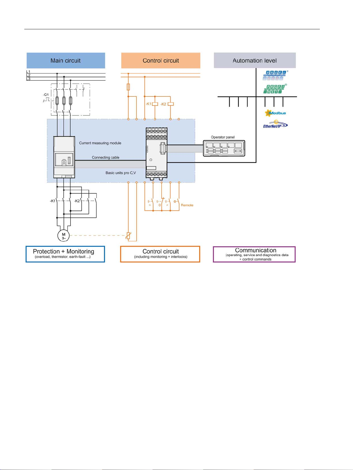
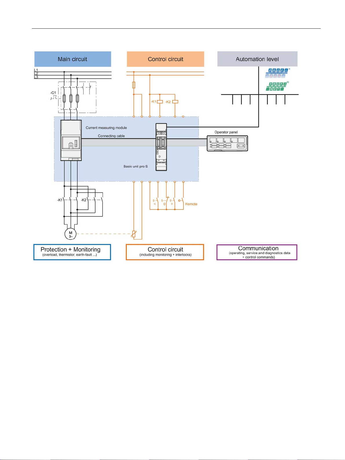
● The quantity of cabling required between the motor feeder and the PLC is reduced
significantly by connecting the entire motor feeder to the process control system via the
fieldbus (see Figures "SIMOCODE pro, integrated in the main circuit, control circuit and at
automation level (PLC)")
● Automated processes are decentralized by means of configurable control and monitoring
functions in the feeder. This saves automation system resources and ensures that the
feeder is fully functional and protected even if the control system or bus system fails.
● By recording and monitoring operating, service and diagnostics data in the feeder and
process control system, plant availability is increased, and the feeder is easier to service
and maintain.
● The user can implement plant-specific requirements for every motor feeder thanks to the
high degree of modularity.
● SIMOCODE pro provides compact solutions and different levels of functions for every
customer application.
● By replacing the control circuit hardware with an integrated control function, the quantity
of required hardware components with wiring is reduced. This drives down storage costs
and limits potential wiring errors.
● Using electronic full motor protection allows the motors to be used more efficiently and
ensures that the tripping characteristic remains stable and the tripping response stays the
same, even after many years.
SIMOCODE pro
System Manual, 05/2019, A5E40507475002A/RS-AD/004
29
Page 30
Advantages/benefits/configuration with SIMOCODE pro
2.1 Advantages/benefits
Figure 2-1 SIMOCODE pro C, pro V, integrated in the main circuit, control circuit and at automation level (PLC)
SIMOCODE pro
30 System Manual, 05/2019, A5E40507475002A/RS-AD/004
Page 31
Advantages/benefits/configuration with SIMOCODE pro
2.1 Advantages/benefits
Figure 2-2 SIMOCODE pro S, integrated in the main circuit, control circuit and at automation level (PLC)
SIMOCODE pro
System Manual, 05/2019, A5E40507475002A/RS-AD/004
31
Page 32

Advantages/benefits/configuration with SIMOCODE pro
2.2 Independent operation
2.2 Independent operation
SIMOCODE pro protects and controls the motor feeder, independently of the automation
system. Even if the automation system (PLC) fails, or if communication is disrupted, the
motor feeder remains fully protected and controllable. SIMOCODE pro can be used without
being connected to the fieldbus. This can easily be connected later, if required.
SIMOCODE pro
32 System Manual, 05/2019, A5E40507475002A/RS-AD/004
Page 33
Advantages/benefits/configuration with SIMOCODE pro
2.3 Simplifying configuration with SIMOCODE pro
2.3 Simplifying configuration with SIMOCODE pro
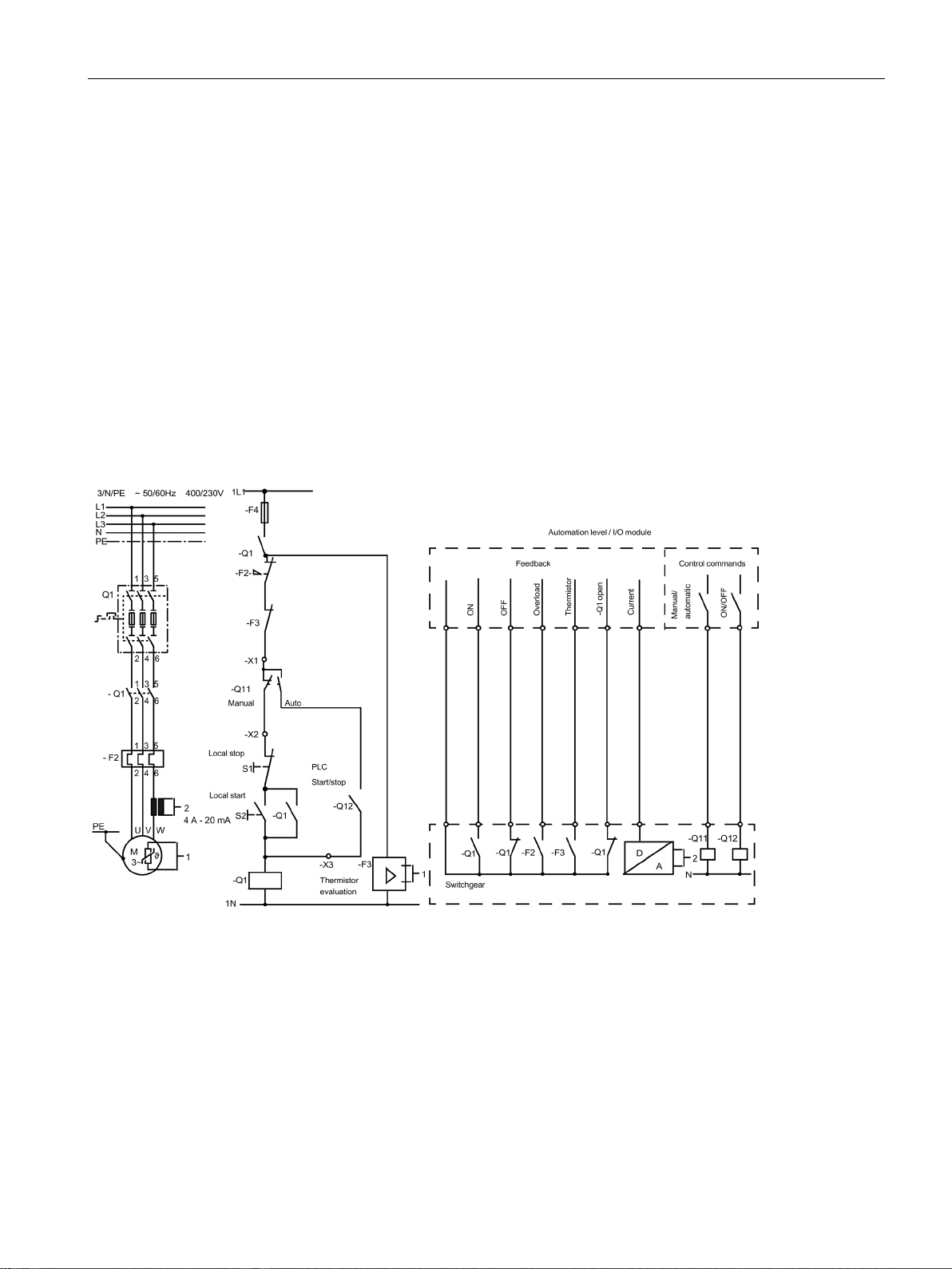
Conventional configuration without SIMOCODE pro
Individual components are used for control, monitoring and signal pre-processing. The
component and wiring requirements for this type of configuration are as follows:
● Use and wiring of overload relays, thermistor evaluation devices, current transformers
and analog/digital converters
● Wiring of the control circuit
● Connection of start / stop control devices
● The contactor must be brought into locking mode via the auxiliary switches
● Wiring of the interlocks
The following figure illustrates the conventional configuration of a direct starter:
Figure 2-3 Conventional configuration of a motor feeder (direct starter)
SIMOCODE pro
System Manual, 05/2019, A5E40507475002A/RS-AD/004
33
Page 34
Advantages/benefits/configuration with SIMOCODE pro
2.3 Simplifying configuration with SIMOCODE pro
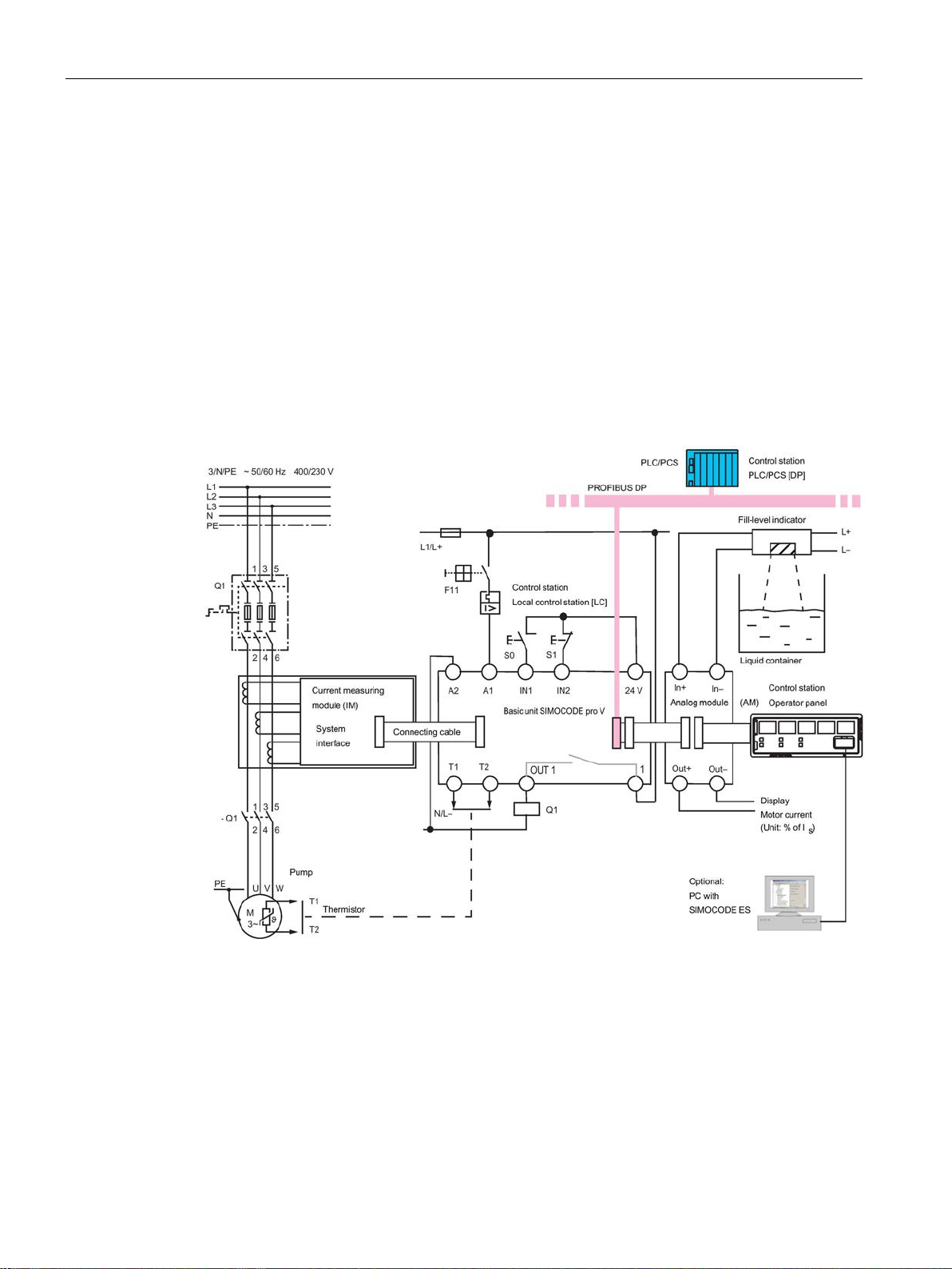
Configuration with SIMOCODE pro
SIMOCODE pro only is used to perform all control, monitoring and signal pre-processing
functions.
The advantages of this configuration are as follows:
● Additional overload relays, thermistor evaluation devices, current transformers and
analog/digital converters are not necessary.
● The wiring of the control circuit (interlocking) is simplified.
● The start and stop switches are wired directly to the inputs of the basic unit.
● The contactor coil is energized via the output of the basic unit. An auxiliary contact for
locking is not required.
The following figure illustrates a configuration with SIMOCODE pro connected to
PROFIBUS:
Figure 2-4 Configuration of a load feeder (direct-on-line starter) with SIMOCODE pro
SIMOCODE pro
34 System Manual, 05/2019, A5E40507475002A/RS-AD/004
Page 35
Advantages/benefits/configuration with SIMOCODE pro
2.4 Typical configuration
2.4 Typical configuration
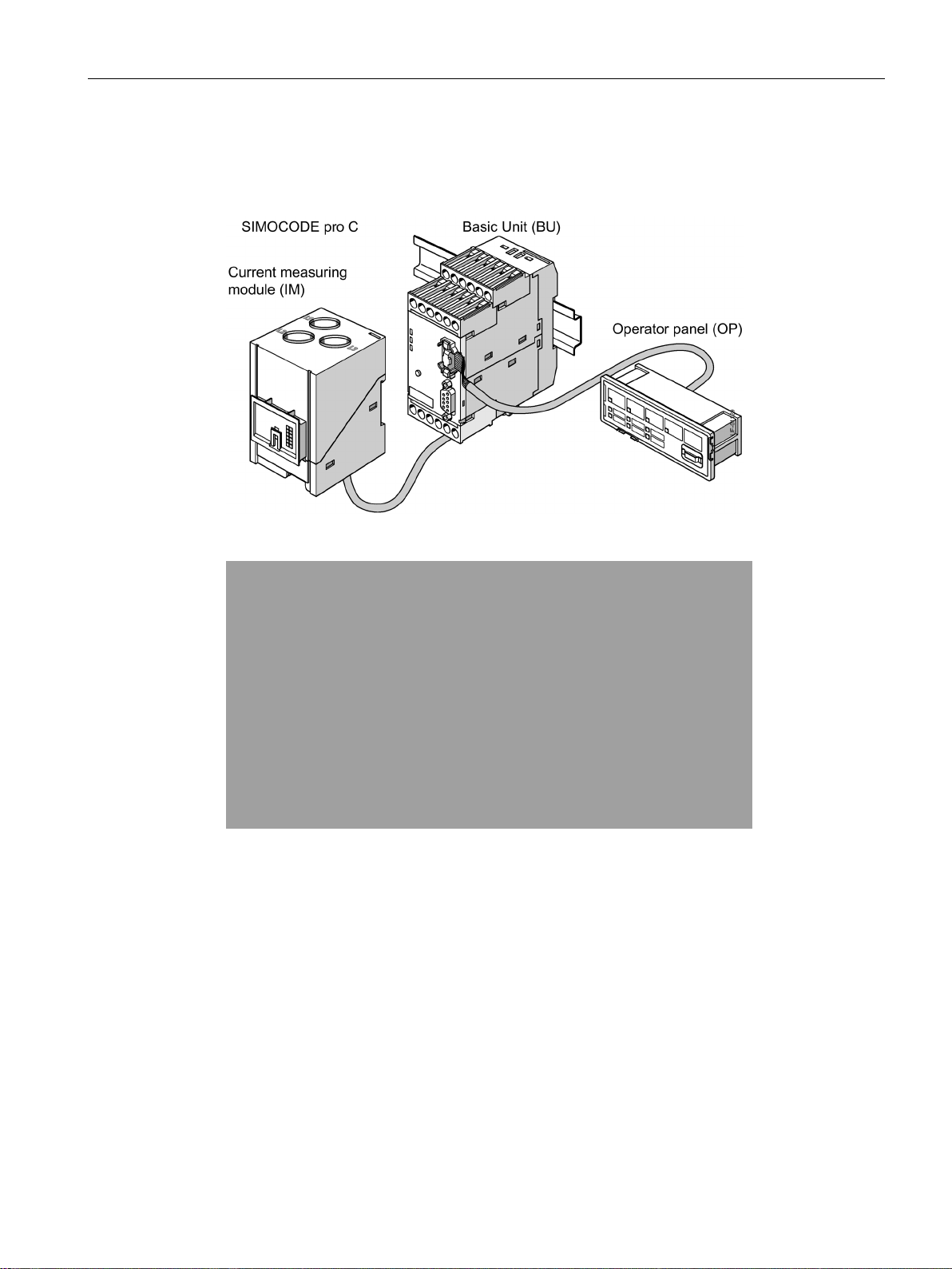
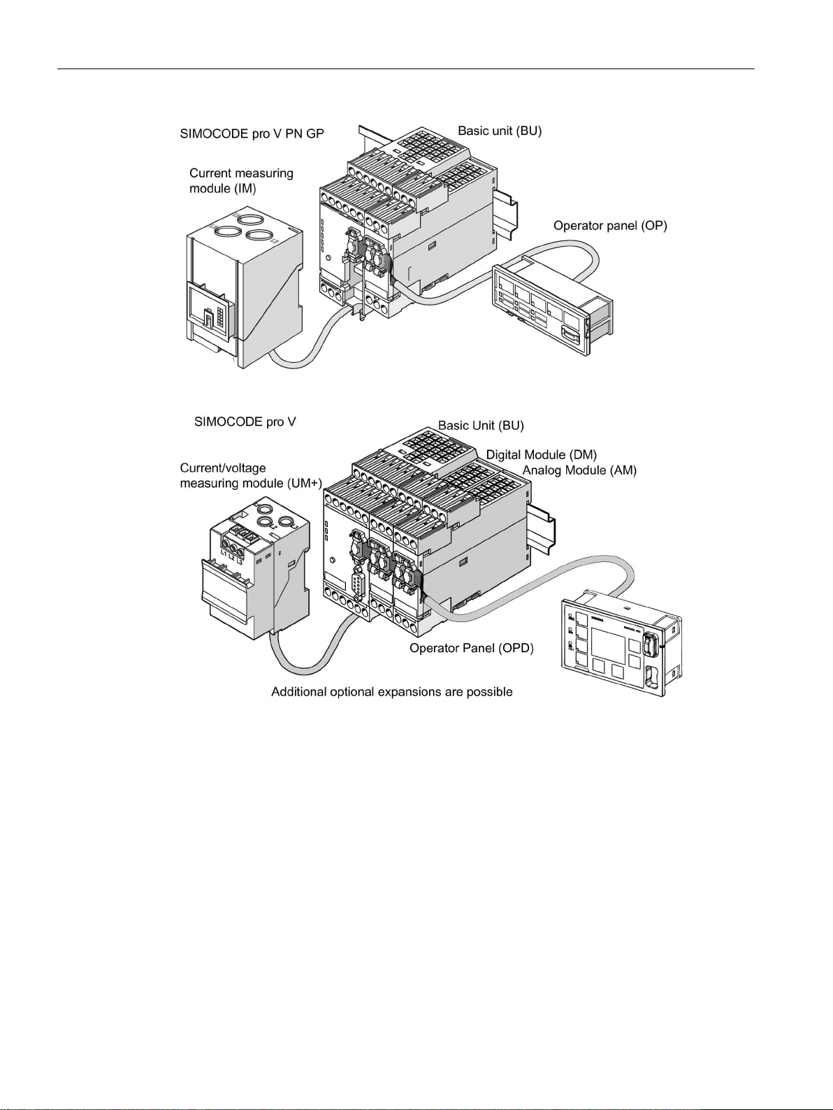
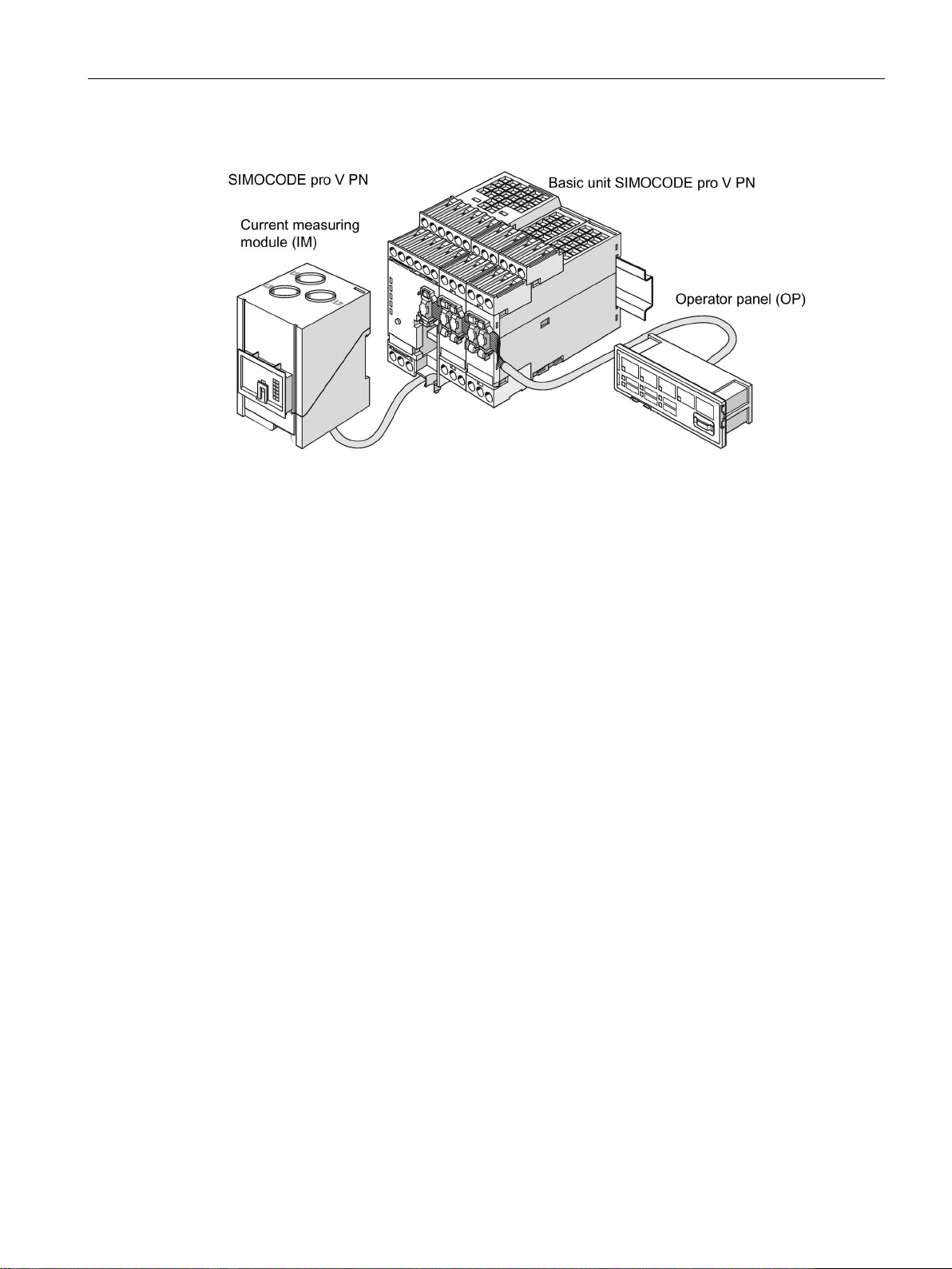
The following figures show typical hardware configurations:
Figure 2-5 Typical SIMOCODE pro C hardware configuration
Figure 2-6 Typical SIMOCODE pro S hardware configuration
SIMOCODE pro
System Manual, 05/2019, A5E40507475002A/RS-AD/004
35
Page 36
Advantages/benefits/configuration with SIMOCODE pro
2.4 Typical configuration
Figure 2-7 Typical SIMOCODE pro V PN GP hardware configuration
Figure 2-8 Typical SIMOCODE pro V PROFIBUS/Modbus RTU hardware configuration
SIMOCODE pro
36 System Manual, 05/2019, A5E40507475002A/RS-AD/004
Page 37
Advantages/benefits/configuration with SIMOCODE pro
2.4 Typical configuration
Figure 2-9 Typical SIMOCODE pro V PN/EtherNet/IP hardware configuration
For information about system components, see Chapter Description of system components
(Page 81).
SIMOCODE pro
System Manual, 05/2019, A5E40507475002A/RS-AD/004
37
Page 38

Advantages/benefits/configuration with SIMOCODE pro
2.4 Typical configuration
SIMOCODE pro
38 System Manual, 05/2019, A5E40507475002A/RS-AD/004
Page 39

3
SIMOCODE pro is often used for automated processes where plant downtimes are very
expensive (e.g. steel or cement industry) and where it is important to prevent plant
downtimes through detailed operating, service and diagnostics data or to localize the fault
very quickly in the event of a fault.
SIMOCODE pro is modular and space-saving and suited especially for operation in motor
control centers (MCC) in the process industry and in power plants.
Applications:
● Protection and control of motors:
– in hazardous areas for different types of protection according to the ATEX
Directive 2014/34/EU (see also Section Safety and commissioning information for Ex
areas (Page 303))
– Heavy-starting motors (paper, cement and metal industries; water management)
– In high-availability plants (chemical, oil, and raw material processing industry, power
plants)
● Dry-running protection of centrifugal pumps by active power monitoring of motors and
shutdown if power consumption falls below a minimum value – especially also including
hazardous areas
– Type of ignition protection b "Control of ignition sources", ignition protection
system b1, approval according to DIN EN ISO 80079-37
– Approval according to ATEX Directive 2014/34/EU and IEC Ex
See also Chapter Dry-running protection for centrifugal pumps by active power
monitoring (Page 314) in the safety and commissioning information for Ex areas.
SIMOCODE pro is especially designed for the chemical industry (including oil and gas), the
steel industry, water management, and the paper, pharmaceutical, cement and glass
industries. Further applications include power plant engineering and diamond, gold and
platinum mines. Based on the experience gained with the predecessor system
SIMOCODE DP, SIMOCODE pro has been tailored even more specifically to the
requirements of these industries. The availability of motors and thus the entire process plays
an important role in these industries. Downtimes caused by faults often lead to high costs.
This is why it is even more important to detect potential faults early on and to initiate
targeted, preventative measures. SIMOCODE pro provides the user with a motor
management system based on years of experience and the latest technology.
SIMOCODE pro
System Manual, 05/2019, A5E40507475002A/RS-AD/004
39
Page 40

Areas of application
SIMOCODE pro
40 System Manual, 05/2019, A5E40507475002A/RS-AD/004
Page 41

4
Multifunction, electronic full motor protection for rated motor currents up to 820 A
SIMOCODE pro provides comprehensive protection of the motor feeder by means of a
combination of delayable, multi-level protection and monitoring functions:
● Current-dependent electronic overload protection (CLASS 5 to 40)
● Thermistor motor protection
● Phase failure/unbalance protection
● Stalled rotor protection
● Monitoring of adjustable limit values for the motor current
● Voltage monitoring
● Active power monitoring
● Dry-running protection for centrifugal pumps by means of active power monitoring
● Monitoring of cos phi (no-load operation/load shedding)
● Ground-fault monitoring
● Temperature monitoring, e.g. using Pt100/Pt1000
● Monitoring of operating hours
● Monitoring of downtimes
● Monitoring the number of starts within a specific period of time
● Safety-related tripping of motor feeders, e.g. fail-safe tripping in the process industry,
locally or via fieldbus (see manual "SIMOCODE pro Safety fail-safe digital modules"
(https://support.automation.siemens.com/WW/view/en/50564852
Recording of measured curves
SIMOCODE pro is able to record measured curves and can, for example, illustrate the
characteristic curve of the motor current during motor startup.
))
SIMOCODE pro
System Manual, 05/2019, A5E40507475002A/RS-AD/004
41
Page 42

Features
Flexible motor control with integrated control functions
(instead of extensive hardware interlocks):
SIMOCODE pro has many pre-defined, integrated motor control functions, including all
necessary connections and interlocks:
● Overload relay
● Direct starter (direct-on-line starter)
● Reversing starter
● Star-delta starter, also with direction reversal
● Two speeds, motors with separate windings (pole-changing starter), also with direction of
rotation reversal
● Two speeds, motors with separate Dahlander windings, also with direction of rotation
reversal
● Positioner control
● Solenoid valve control
● Actuation of a circuit breaker
● Soft starter control, possibly combined with reversing starter
These control functions are pre-defined in SIMOCODE pro and can be assigned freely to
device inputs and outputs.
These pre-defined control functions can also be adjusted flexibly to meet customer
requirements of the motor feeder, without requiring additional auxiliary relays in the control
circuit. This is achieved by means of freely parameterizable logic modules (truth tables,
counters, timers, pulse width modulators, etc.) and standard functions (power failure
monitoring, emergency start, external fault monitoring, etc.).
Detailed operating, service and diagnostics data:
SIMOCODE pro provides a range of operating, service and diagnostics data and helps to
detect impending faults in good time and stop these occurring with preventative measures. If
a fault occurs, it can be diagnosed, traced and resolved within a short period of time. Plant
downtime is thus reduced to a minimum or does not occur at all. See Chapter Overview of
functions (Page 47).
Communication:
The SIMOCODE pro basic units have integrated communication bus interfaces and are thus
able to replaces all individual wiring and distribution boxes normally required to exchange
data with a higher-level automation system with a single bus cable.
SIMOCODE pro
42 System Manual, 05/2019, A5E40507475002A/RS-AD/004
Page 43

Features
Communication through PROFIBUS:
PROFIBUS stands for Process Field Bus. PROFIBUS is a multi-vendor standard for the
networking of field devices (e.g. PLCs, drives, actuators, or sensors) in compliance with the
European process and fieldbus standard (PROFIBUS standard EN 50170, Volume 2, PROFIBUS). It specifies the functional, electrical and mechanical characteristics of a bitserial fieldbus system.
PROFIBUS is a bus system that networks PROFIBUS-compatible automation systems and
field devices at the cell and field level. PROFIBUS is available with the DP (= Distributed
Peripherals), FMS (= Fieldbus Message Specification), PA (= Process Automation), or
TF (= Technological Functions) protocol.
PROFIBUS DP is a bus system with the DP (distributed I/O) protocol. The main task of
PROFIBUS DP is to manage the fast, cyclic data exchange between the central DP devices
and the I/O devices.
PROFIBUS DPV1 is the extension of the DP protocol. It enables acyclic data exchange of
parameter, diagnostic, receive and test data.
SIMOCODE pro C, pro S and pro V support, among others:
● Baud rates up to 1.5 Mbit / s or 12 Mbit / s
● Automatic baud rate detection
● Communication with one master (class 1) and up to two masters (class 2)
● Time stamp with high timing precision (SIMATIC S7) for SIMOCODE pro V
● Cyclic services (DPV0) and acyclic services (DPV1)
● DPV1 communication downstream from the Y-Link.
See Chapter "PROFIBUS communication" in the manual SIMOCODE pro - Communication
(https://support.industry.siemens.com/cs/ww/en/view/109743960
).
SIMOCODE pro
System Manual, 05/2019, A5E40507475002A/RS-AD/004
43
Page 44

Features
Communication via PROFINET:
PROFINET (Process Field Network) is the open Industrial Ethernet Standard from Profibus &
Profinet International (PI) for automation.
Within the context of Totally Integrated Automation (TIA), PROFINET is the systematic
continuation of PROFIBUS DP, the established fieldbus, and Industrial Ethernet, the
communication bus for the cell level. Experiences from both systems have been and are
being integrated in PROFINET.
SIMOCODE pro V PN (High Performance unit) has two integrated PROFINET interfaces and
provides communication functions via PROFINET IO with the following properties:
● Integrated switch with two ports
● Device replacement without removable medium/programming device
● Shared device in combination with DF-FP modules
● Media redundancy
● System redundancy
● RT communication
● Support for PROFIenergy
SIMOCODE pro V PN GP (General Performance unit) has one/two integrated PROFINET
interface(s) and provides communication functions via PROFINET IO with the following
properties:
● Integrated switch with two ports (device with two ports)
● Device replacement without removable medium/programming device
● Shared device in combination with DF-FP modules
● Media redundancy (device with two ports)
● System redundancy
● RT communication
● Support for PROFIenergy
See Chapter "PROFINET communication" in the manual SIMOCODE pro - Communication
(https://support.industry.siemens.com/cs/ww/en/view/109743960
).
SIMOCODE pro
44 System Manual, 05/2019, A5E40507475002A/RS-AD/004
Page 45

Features
Communication via Modbus:
Modbus RTU (Remote Terminal Unit) is a standard protocol for network communication and
uses the electrical RS485 connection for serial data transmission between Modbus devices
in the network.
Modbus RTU uses a master/slave network in which the entire communication is triggered by
only one master device while the slaves can only respond to the request of the master. The
master sends a request to a slave address and only this slave address responds to the
command (exception: broadcast frames to slave address 0 that are not acknowledged by the
slaves).
SIMOCODE pro V Modbus devices have been developed in accordance with the "MODBUS
over serial line specification and implementation guide" (available at www.modbus.org
(http://www.modbus.org
)). You can find the relevant information on establishing Modbus
RTU communication in this specification. The key points for a Modbus RTU communication
network ("Multipoint System requirements") listed in the specification apply equally for a
communication network with SIMOCODE devices.
See Chapter "Modbus communication" in the manual SIMOCODE pro - Communication
(https://support.industry.siemens.com/cs/ww/en/view/109743960
).
Communication via EtherNet/IP:
EtherNet/IP (EtherNet Industrial Protocol, often simply called EIP) is a real-time Ethernet that
is used mainly in automation engineering. EtherNet/IP was developed by Allen-Bradley and
was later handed over to the Open DeviceNet Vendor Association (ODVA) as an open
standard. See Open DeviceNet Vendor Association (http://www.odva.org
).
Besides PROFINET and Modbus/TCP, EtherNet/IP is an Ethernet-based fieldbus that is
currently widely spread.
SIMOCODE pro V EtherNet/IP devices were developed in compliance with the EtherNet/IP
standard and have the following properties:
● Integrated switch with two ports
● Media redundancy via Device Level Ring (DLR)
● System redundancy (as of E03).
See Chapter "EtherNet/IP communication" in the manual SIMOCODE pro - Communication
(https://support.industry.siemens.com/cs/ww/en/view/109743960
).
SIMOCODE pro
System Manual, 05/2019, A5E40507475002A/RS-AD/004
45
Page 46

Features
SIMOCODE pro
46 System Manual, 05/2019, A5E40507475002A/RS-AD/004
Page 47

5
5.1 Protection functions
Detailed description: See Chapter "Motor protection" in the manual
Parameterizing SIMOCODE pro
(https://support.industry.siemens.com/cs/ww/en/view/109743958
Overload protection
Current-dependent electronic protection of three-phase and AC motors with adjustable
tripping characteristics (class times) according to IEC 60947-4-1 requirements.
Unbalance protection
Protects motors from excessive temperatures caused by excessive phase unbalance.
).
Phase failure protection
Protects motors from excessive temperatures caused by phase failure.
Stalled rotor protection
Immediate trip after the motor current overshoots an adjustable threshold.
Thermistor protection
SIMOCODE pro provides the option of connecting thermistor sensors (binary PTC) for
monitoring the motor temperature.
SIMOCODE pro
System Manual, 05/2019, A5E40507475002A/RS-AD/004
47
Page 48
Overview of functions
WARNING
Installation in potentially explosive atmospheres
5.1 Protection functions
Dry-running protection for centrifugal pumps
The following high performance devices with PTB 18 ATEX 5003 X can be used to
implement dry-running protection of centrifugal pumps (non-electrical devices) through active
power monitoring and motor shutdown:
● SIMOCODE pro V PB from version *E16*
● SIMOCODE pro V PN from version *E13*
● SIMOCODE pro V EIP from version *E04*
This applies to centrifugal pumps with progressive flow characteristics, which are also
suitable for pumping flammable media and are also installed in hazardous areas.
SIMOCODE pro itself is not suitable for installation in potentially explosive atmospheres!
If the active power, and thus the flow rate, falls below a minimum value, the motor - and thus
the centrifugal pump - is switched off The devices support monitoring of the minimum flow
rate for a freely selectable minimum value. A delay time (effective during operation including
the pump's regular switch-off) can be specified to minimize the probability of incorrect
tripping in addition to the parameter for the trip level of the minimum active power (which
corresponds to a minimum flow rate). During the start-up procedure, operation with active
power below the trip level can constitute a regular operating status of short duration
(depending on the procedure used to open the pressure-side shut-off valve). For this reason,
a start-up bridging time can be specified to prevent incorrect tripping during the start-up
procedure.
The parameters can be entered using the "SIMOCODE ES" (TIA Portal) engineering
software.
It is also possible to determine the trip level in a "teach-in" and to enter the further
parameters with the aid of menu-guided input screens. Using this method, the operating
point with optimum flow rate and the point with minimum flow rate are started up with real
operating medium, as a result of which the trip level of the minimum active power is
determined. The teach-in has to be repeated following any changes in the pump or system
characteristics (e.g. as a result of changing the operating medium or of intervention in the
plant configuration).
With regard to dry-running protection for centrifugal pumps, a current/voltage measuring
module especially intended for this function is also required in addition to the basic unit.
See also:
● Chapter "Dry-running protection for centrifugal pumps by active power monitoring
(Page 314)" in the safety and commissioning information for Ex areas
● Chapter "Dry-running protection for centrifugal pumps" in the manual Parameterizing
SIMOCODE pro (https://support.industry.siemens.com/cs/ww/en/view/109743958
).
SIMOCODE pro
48 System Manual, 05/2019, A5E40507475002A/RS-AD/004
Page 49

Overview of functions
5.2 Monitoring functions
5.2 Monitoring functions
Detailed description: See Chapters "Monitoring functions" and "Logic blocks" in the manual
Parameterizing SIMOCODE pro
(https://support.industry.siemens.com/cs/ww/en/view/109743958
Current limit monitoring
Current limit monitoring is used for process monitoring. This enables incipient anomalies in
the system to be detected in good time. If a current limit is exceeded but still below the
overload limit, it can, for example, indicate a dirty filter on a pump, or an increasingly
sluggish motor bearing. If the current limit is undershot, it can be the first sign of a worn-out
drive motor belt.
Ground-fault monitoring
Residual current monitoring relays are used in industry to
● Protect systems from damage caused by residual currents
).
● Prevent production losses caused by unplanned downtime
● Perform maintenance to meet all demands.
Basic units have:
● An internal ground-fault monitoring system: For motors with a 3-wire connection, the
basic unit calculates a possible fault current/ground-fault current from the total current via
a current measuring module or a current / voltage measuring module. Internal
ground-fault monitoring is only possible for motors with a 3-phase connection in networks
that are either grounded directly or grounded with low impedance.
● External ground-fault monitoring in SIMOCODE pro S and SIMOCODE pro V
4)
: The
external ground-fault monitoring using residual current transformer 3UL23 and
ground-fault module is normally used in the following cases:
– in cases in which power systems are grounded with high impedance
– in cases, in which precise detection of the ground-fault current is necessary, for
example, for condition monitoring.
A ground-fault module can be used to create an additional input on the
SIMOCODE pro V and SIMOCODE pro V PN GP basic units to connect a 3UL23 residual
current transformer.
A multifunction module can be used to create an additional input on the
SIMOCODE pro S basic unit to connect a 3UL23 residual current transformer.
With ground-fault detection using the 3UL23 residual current transformer, it is possible to
determine the precise residual current as a measured value, and to define freely
selectable warning and trip limits in a wide range from 30 mA - 40 A.
See also Chapter "External ground-fault monitoring with 3UL23 residual current
transformer" in the manual Parameterizing SIMOCODE pro
(https://support.industry.siemens.com/cs/ww/en/view/109743958
SIMOCODE pro
System Manual, 05/2019, A5E40507475002A/RS-AD/004
).
49
Page 50

Overview of functions
5.2 Monitoring functions
Voltage monitoring
1)
High Performance SIMOCODE pro V allows voltage monitoring of a three-phase current
network or a single-phase network for undervoltage or further availability:
● Monitoring for undervoltage: Two-level monitoring for freely selectable limits. The
response of SIMOCODE pro on reaching a prewarning level or trip level can be freely
parameterized.
● Monitoring for further availability: Even when the motor is switched off, SIMOCODE pro
can indicate the further availability of the feeder by measuring the voltage directly at the
circuit breaker or fuses.
Temperature monitoring
The SIMOCODE pro S, SIMOCODE pro V and SIMOCODE pro V PN GP devices offer the
option of implementing analog temperature monitoring, e.g. of the motor windings or the
bearings - SIMOCODE pro S with the multifunction module,
SIMOCODE pro V/SIMOCODE pro V PN with the temperature module.
SIMOCODE pro S and SIMOCODE pro V support two-level monitoring for overtemperature
for freely selectable limit values. The response of SIMOCODE pro on reaching a prewarning
level or trip level can be freely parameterized and delayed. Temperature monitoring takes
into account the highest temperature of all the sensor measuring circuits in use.
2)
Active power monitoring
The active power curve of a motor reflects its actual load. Excess load results in increased
wear of the motor and, thus, may lead to premature motor failure. Excessively low active
power can indicate no-load operation of the motor, for example.
High Performance SIMOCODE pro V offers the option of two-level active power monitoring
for freely selectable upper and lower limits respectively. The response on reaching a
prewarning level or trip level can be freely parameterized and delayed.
Cos phi monitoring
1)
The power factor fluctuates more than the motor current, particularly in the low-end
performance range of a motor. For this reason, the monitoring of the power factor comes into
consideration for the detection of faults. Examples: Breakage of a drive belt or drive shaft
High Performance SIMOCODE pro V enables two-level monitoring of the power factor cos
phi for freely selectable minimum limits. The devices' response on reaching a prewarning
level or trip level can be freely parameterized and delayed.
1)
SIMOCODE pro
50 System Manual, 05/2019, A5E40507475002A/RS-AD/004
Page 51

Overview of functions
5.2 Monitoring functions
Monitoring operating hours, stop time, and number of starts
SIMOCODE pro can monitor the operating hours and stop times of a motor to avoid plant
downtimes due to failed motors caused by either running too long (wearing out) or being
stopped for too long. For example, if an adjustable limit value is exceeded, a signal indicating
that the relevant motor requires maintenance or replacement can be generated. After the
motor has been replaced, the operating hours and stop times can be reset.
To avoid excessive thermal loads and premature aging of a motor, the number of motor
starts in a selected time frame can be limited. The limited number of possible starts can be
indicated by pre-warnings.
Monitoring additional process variables via the analog module 3)
High Performance SIMOCODE pro V allows measuring and monitoring of any other process
variables via the analog module.
For example, the fill level can be monitored to protect a pump against dry operation, or a
differential pressure transducer can be used to monitor the degree of pollution in a filter. If
the fill level undershoots a specified level, the pump can be switched off and, if a specific
differential pressure value is exceeded, the filter should be cleaned.
The devices support two-phase monitoring of the applicable process variable for freely
selectable upper and lower current limits. The response of SIMOCODE pro on reaching a
prewarning level or trip level can be freely parameterized and delayed.
Phase sequence identification
1)
SIMOCODE pro allows the direction of rotation of a motor to be determined by identification
of the phase sequence. If the direction of rotation is wrong, a signal can be generated or the
motor switched off. See Chapter Menu of the operator panel with display (Page 94).
Monitoring any measured values using unrestricted limit monitors
SIMOCODE pro can monitor every measured value in the system for undershooting or
overshooting a set threshold value by means of unrestricted limit monitors, e.g. the
frequency
Parameterizing SIMOCODE pro
(https://support.industry.siemens.com/cs/ww/en/view/109743958
1) For use with current / voltage measuring module
2) Temperature module or multifunction module additionally required
3) Analog module additionally required
1)
. Further information can be found in Chapter "Limit monitors" in the manual
).
4) SIMOCODE pro V and pro S device types: Ground-fault module or multifunction module
and residual current transformer additionally required
See also
Dry-running protection for centrifugal pumps by active power monitoring (Page 314)
SIMOCODE pro
System Manual, 05/2019, A5E40507475002A/RS-AD/004
51
Page 52

Overview of functions
CAUTION
Loss of safety function is possible
5.3 Safety-oriented tripping
5.3 Safety-oriented tripping
The SIMOCODE pro motor management system has two modules for the safety-related
tripping of motors:
● Fail-safe digital module DM-F local: For applications requiring safety-related tripping of a
motor feeder via a hardware signal that is acquired and evaluated by the module.
● DM-F PROFIsafe fail-safe digital module: For applications that require the safety-related
tripping of a motor feeder by a fail-safe controller (F-CPU) via the communication bus with
the fail-safe PROFIsafe profile.
These modules conform to the general requirements for EMERGENCY STOP devices or
safety circuits described in EN 418 and EN 60204-1 (06.2006).
Depending on the external circuit, the following Performance Level / Safety Integrity Level
can be achieved:
● PL e with Category 4 according to ISO 13849-1 or
● SIL 3 according to IEC 61508/62061
Safety technology and safety-related functions
● Are exclusively restricted to the fail-safe digital modules.
● Do not directly affect existing SIMOCODE pro components and concepts.
A more detailed description is provided in the documentation listed below
● Manual Fail-safe Digital Modules SIMOCODE pro, German
(https://support.automation.siemens.com/WW/view/de/50564852
)
● Manual Fail-safe Digital Modules SIMOCODE pro, English
(https://support.automation.siemens.com/WW/view/de/50564852/0/en
)
● Manual Fail-safe Digital Modules SIMOCODE pro, French
(https://support.automation.siemens.com/WW/view/de/50564852/0/fr
)
● Manual Fail-safe Digital Modules SIMOCODE pro, Spanish
(https://support.automation.siemens.com/WW/view/de/50564852/0/es
)
● Operating instructions "Fail-Safe Digital Module DM-F Local"
(https://support.automation.siemens.com/WW/view/en/49222263
)
● Operating instructions "Fail-Safe Digital Module DM-F PROFIsafe"
(https://support.automation.siemens.com/WW/view/en/49222281
).
You will find the System Manuals and Operating Instructions at Manuals/operating
instructions (https://support.industry.siemens.com/cs/ww/en/ps/16027/man
)
For the 24 V DC power supply, always use an SELV or PELV power supply unit!
For capacitive and inductive loads, an adequate protective circuit is required!
SIMOCODE pro
52 System Manual, 05/2019, A5E40507475002A/RS-AD/004
Page 53

Overview of functions
Control function
SIMOCODE pro
BP
GP
HP
C
S
V PN GP
V PB, V MR, V PN, V EIP
Overload relay
✓ ✓ ✓
✓
Direct starter (direct-on-line starter)
✓ ✓ ✓
✓
Reversing starter
✓ ✓ ✓
✓
Star-delta starter
— ✓ ✓
✓
reversing starter
reversing starter
Solenoid valve
— — —
✓
Positioner — — — ✓
Soft starter
— ✓ ✓
✓
Soft starter with reversing contactor
— — —
✓
5.4 Control functions
5.4 Control functions
Depending on the device series, the following parameterizable control functions are
available:
Table 5- 1 Control functions
Molded case circuit breaker (MCCB) ✓ ✓ ✓ ✓
Star-delta reversing starter — — — ✓
Dahlander starter, combinable with
— — — ✓
Pole-changing starter, combinable with
All the necessary protection functions and interlocks are already available and can be flexibly
adapted and expanded.
For a detailed description of the individual control functions: See Chapter "Motor control" in
the manual Parameterizing SIMOCODE pro
(https://support.industry.siemens.com/cs/ww/en/view/109743958
— — — ✓
).
SIMOCODE pro
System Manual, 05/2019, A5E40507475002A/RS-AD/004
53
Page 54

Overview of functions
Service
SIMOCODE pro
C S V PB
Baud rates of up to 12 Mbit / s via Sub-D socket
✓ — ✓
Baud rates of up to 1.5 Mbit / s via terminal connection
✓ ✓ ✓
Cyclic services (DPV0) and acyclic services (DPV1)
✓ ✓ ✓
Operation as DPV1 slave downstream from the Y link
✓ ✓ ✓
Alarms according to DPV1
✓ ✓ ✓
Time synchronization via PROFIBUS DP
— — ✓
3UF50 compatibility mode
— — ✓
Safety-related tripping "PROFIsafe"
— — ✓
5.5 Communication
5.5 Communication
PROFIBUS DP
SIMOCODE pro has an integrated PROFIBUS DP interface (SUB D socket or terminal
connection on the basic units). SIMOCODE pro supports the following services, for example:
Table 5- 2 PROFIBUS DP services
Automatic baud rate detection ✓ ✓ ✓
Modbus RTU
Detailed description: See Chapter "PROFIBUS DP communication" in the
manual SIMOCODE pro - Communication
(https://support.industry.siemens.com/cs/ww/en/view/109743960
).
SIMOCODE pro V Modbus RTU possesses integrated Modbus RTU communication
functions.
Detailed description: See Chapter "Modbus communication" in the
manual SIMOCODE pro - Communication
(https://support.industry.siemens.com/cs/ww/en/view/109743960
).
SIMOCODE pro
54 System Manual, 05/2019, A5E40507475002A/RS-AD/004
Page 55

Overview of functions
Note
Use of PORT connections with SIMOCODE pro V PN GP basic units
Only PORT
5.5 Communication
PROFINET
PROFINET IO
SIMOCODE pro V PN and pro V PN GP have integrated PROFINET IO device
communication functions, such as:
● Integrated switch with two RJ45 ports
● Ethernet services: ping, arp, network diagnostics (SNMP) / BIB-2, LLDP, NTP
● Port diagnostics
● Deactivation of ports
● Media redundancy
● Shared device
● Device replacement without PG/PC
● I/O data
● Diagnostics and maintenance alarms
● Data records
● PROFIenergy
● PROFIsafe
1 can be used with SIMOCODE pro V PN GP 3UF7011-1A.00-2 basic units
OPC UA
In addition to the PROFINET IO device communication functions, SIMOCODE pro V PN also
has OPC UA server functions. Using these functions, an OPC UA client can access
SIMOCODE pro V PN data.
Web server
In addition to the PROFINET IO device communication functions, both the
SIMOCODE pro V PN High Performance device and the SIMOCODE pro V PN General
Performance device have an integrated web server function that permits access to the
service and diagnostic data from a PC on which a web browser is installed.
Detailed descriptions: See Chapter "PROFINET communication" in the
manual SIMOCODE pro - Communication
(https://support.industry.siemens.com/cs/ww/en/view/109743960
).
SIMOCODE pro
System Manual, 05/2019, A5E40507475002A/RS-AD/004
55
Page 56

Overview of functions
5.5 Communication
EtherNet/IP
SIMOCODE pro V EtherNet/IP has integrated EtherNet/IP communication functions:
● Integrated switch with two RJ45 ports
● Assembly objects for integration in cyclic communication with the controller
● CIP objects
● Application objects for access to SIMOCODE data such as measured values, statistics
data, diagnostics and selected parameters
● Device Level Ring support
● Ethernet services: ping, arp, network diagnostics (SNMP)/BIB-2, LLDP, NTP
● Port diagnostics
● Deactivation of ports
Detailed description: See Chapter "EtherNet/IP communication" in the
manual SIMOCODE pro - Communication
(https://support.industry.siemens.com/cs/ww/en/view/109743960
).
Web server
In addition to the EtherNet/IP communication functions, SIMOCODE pro V EIP has an
integrated web server function that permits access to the service and diagnostic data from a
PC on which a web browser is installed.
Detailed descriptions: See Chapter "EtherNet/IP communication" in the
manual SIMOCODE pro - Communication
(https://support.industry.siemens.com/cs/ww/en/view/109743960
"SIMOCODE pro - Communication".
)
SIMOCODE pro
56 System Manual, 05/2019, A5E40507475002A/RS-AD/004
Page 57

Overview of functions
Standard function
SIMOCODE pro
BP
GP
HP
C
Number
S
Number
V PN GP
Number
V PB
Number
V MR
Number
V PN
Number
V EIP
Number
Test 2 2 2 2 2 2
2
Reset 3 3 3 3 3 3
3
(TPF)
Off (OPO)
(UVO)
Emergency start
1 1 1 1 1 1 1
(PLC / PCS monitoring)
Time stamping
— — — 1 1 — —
"Local"
5.6 Standard functions
5.6 Standard functions
Standard functions are pre-defined functions that can be easily activated,
e.g. time-staggered restart of the drives after a power failure. SIMOCODE pro has the
following standard functions:
Table 5- 3 Standard functions
Test Position Feedback
External fault 4 4 4 6 6 6 6
Operational Protection
Power failure monitoring
Watchdog
Safety-related tripping
1 1 1 1 1 1 1
— — — 1 1 1 1
— — — 1 1 1 1
1 1 1 1 1 1 1
— — — 1 1 1 1
Detailed description: See Chapter "Standard functions" in the manual Parameterizing
SIMOCODE pro (https://support.industry.siemens.com/cs/ww/en/view/109743958
).
SIMOCODE pro
System Manual, 05/2019, A5E40507475002A/RS-AD/004
57
Page 58

Overview of functions
Logic module
SIMOCODE pro
BP
GP
HP
C
Number
S
Number
V PN GP
Number
V PB
Number
V MR
Number
V PN
Number
V EIP
Number
inputs / 1 output
inputs/2 outputs
Timers 2 2 2 4 4 6
6
Counters 2 2 2 4 4 6
6
conditioning
elements
Flashing 3 3 3 3 3 3
3
Flicker 3 3 3 3 3 3
3
Limit monitor
— — — 4 4 6 6
(calculators)
multiplexer
1) from version *E03*
5.7 Freely-programmable logic modules
5.7 Freely-programmable logic modules
If you need any other additional functions for your application, you can use the freely
programmable logic modules. These can be used, for example, to implement logical
operations, time relay functions and counter functions. Furthermore, limit monitors can
monitor any value in SIMOCODE pro for undershooting or overshooting of a freely selected
limit. Depending on the device series, the system provides several freely parameterizable
logic modules:
Table 5- 4 Freely-programmable logic modules
Truth table 3
Truth
table 2 inputs /
1 output
Truth tables 5
Signal
Non-volatile
Calculation
modules
Analog
Pulse width
modulator
3 4 4 6 6 8 8
— 2 2 2 2 2 2
— — — 1 1 1 1
2 4 4 4 4 6 6
2 2 2 4 4 4 4
— — — 2
— — — — — 1 1
— — — — — 1 1
1)
2 4 4
SIMOCODE pro
58 System Manual, 05/2019, A5E40507475002A/RS-AD/004
Detailed description: See Chapter "Logic blocks" in the manual
Parameterizing SIMOCODE pro
(https://support.industry.siemens.com/cs/ww/en/view/109743958
).
Page 59

Overview of functions
5.8 Operating, service and diagnostics data
5.8 Operating, service and diagnostics data
SIMOCODE pro supplies a large amount of detailed operating, service and diagnostics data.
Operating data
● Motor switching state (ON, OFF, LEFT, RIGHT, SLOW, FAST), derived from the current
flow in the main circuit: thus, feedback via auxiliary contacts of circuit breakers and
contactors is not necessary.
● Current in phases 1, 2 and 3 and maximum current in % of current setting
● Voltage in phases 1, 2 and 3 in V
● Frequency
● Active power in W
● Apparent power in VA
● Power factor in %
7)
1)
1)
1)
● Phase unbalance in %
● Phase sequence
● Ground-fault current
1)
6)
1)
● Temperature in the respective sensor measuring circuits, and maximum temperature in
3)
K
● Current analog signal values
4)
● Time to trip in s
● Temperature rise for motor model in %
● Remaining cooling down period of the motor in s, etc.
It is possible to adapt the units via the device-internal conversion of individual measured
values with the help of the logic modules (calculators) provided by SIMOCODE pro. For
example, the temperature recorded by SIMOCODE pro can be calculated in either °F or °C
and transmitted to the automation system via PROFIBUS DP.
SIMOCODE pro
System Manual, 05/2019, A5E40507475002A/RS-AD/004
59
Page 60

Overview of functions
5.8 Operating, service and diagnostics data
Service data
Among other things, SIMOCODE pro provides the following relevant data for maintenance:
● Number of motor operating hours, also resettable
● Motor stop times, also resettable
● Number of motor starts, also resettable
● Number of permissible starts remaining
● Number of overload trips, also resettable
● Feeder power consumption in kWh, also resettable
2)
● Internal feeder-related comments stored in the device, e.g. information regarding
maintenance events, etc.
● Safety-related tripping monitoring in h, also resettable
5)
Diagnostics data
● Numerous detailed early warning and fault messages, also for further processing in the
device or in the control system
● Device-internal error logging with time stamp
● Value of the last trip current
● Feedback faults (e.g. no current flow in the main circuit after switch-on command), etc.
● "Local" and "PROFIsafe" diagnostic messages
1) When using SIMOCODE pro V High Performance basic units with current / voltage
measuring module
2) When using SIMOCODE pro V PB basic units from version *E03* current / voltage
measuring module
3) When using the SIMOCODE pro V basic units with the 3UF77 temperature module or the
SIMOCODE pro S basic unit with multifunction module
4) When using SIMOCODE pro V High Performance basic units with analog module
5) When using SIMOCODE pro V High Performance basic units together with DM-F fail-safe
digital module
6) When using the SIMOCODE pro V basic units with the 3UF7510 ground-fault module or
the SIMOCODE pro S basic unit with a multifunction module and 3UL23 residual current
transformer
7) 2nd generation current / voltage measuring module necessary
SIMOCODE pro
60 System Manual, 05/2019, A5E40507475002A/RS-AD/004
Page 61

6
Function/component
SIMOCODE pro
BP
GP
HP
C
S
V PN GP
V PB
V MR
V PN
V EIP
Control functions
relay
starter
Star-delta starter
— ✓ ✓ ✓ ✓ ✓ ✓
Dahlander starter
— — — ✓ ✓ ✓ ✓
Pole-changing starter
— — — ✓ ✓ ✓ ✓
Soft starter
— ✓ ✓ ✓ ✓ ✓ ✓
Solenoid valve
— — — ✓ ✓ ✓ ✓
reversing function
Protection functions
Overload protection
✓ ✓ ✓ ✓ ✓ ✓ ✓
(binary)
Stalled rotor
✓ ✓ ✓ ✓ ✓ ✓ ✓
Unbalance
✓ ✓ ✓ ✓ ✓ ✓ ✓
Phase failure
✓ ✓ ✓ ✓ ✓ ✓ ✓
Dry-running protection
for centrifugal pumps
by means of active
power monitoring
dry-running protection
Measurement functions
Current measurement
✓ ✓ ✓ ✓ ✓ ✓ ✓
measurement
Monitoring functions
Current limit monitoring
✓ ✓ ✓ ✓ ✓ ✓ ✓
transformer)
Voltage monitoring
— — — ✓ ✓ ✓ ✓
Temperature monitoring
— ✓ ✓ ✓ ✓ ✓ ✓
Active power monitoring
— — — ✓ ✓ ✓ ✓
The following check list should help you decide upon the optimum device series for your
requirements:
Intelligent overload
Direct starter, reversing
Positioner — — — ✓ ✓ ✓ ✓
Can be combined with
Thermistor motor
protection with PTC
Minimum level; in
combination with
current/voltage
measuring modules for
✓ ✓ ✓ ✓ ✓ ✓ ✓
✓ ✓ ✓ ✓ ✓ ✓ ✓
— — — ✓ ✓ ✓ ✓
✓ ✓ ✓ ✓ ✓ ✓ ✓
— — — ✓ — ✓ ✓
SIMOCODE pro
System Manual, 05/2019, A5E40507475002A/RS-AD/004
Current/voltage/power
Ground-fault monitoring
(internal)
Ground-fault monitoring
(residual current
— — — ✓ ✓ ✓ ✓
✓ ✓ ✓ ✓ ✓ ✓ ✓
— ✓ ✓ ✓ ✓ ✓ ✓
61
Page 62

Check list for selecting a device series
Function/component
SIMOCODE pro
BP
GP
HP
C
S
V PN GP
V PB
V MR
V PN
V EIP
monitoring
the analog module
detection
monitors
measuring modules)
Safety functions
Safety-related tripping
— — — ✓ ✓ ✓ ✓
Number of
inputs/outputs
of basic unit
basic unit
modules
Expansion modules
ground-fault monitoring
ground-fault monitoring
relay; 24 V DC inputs
Power factor (cos phi)
Monitoring operating
hours, stop time, and
number of starts
Monitoring additional
process variables via
Phase sequence
Monitoring any
measured values using
unrestricted limit
Frequency
measurement (with the
2nd generation
current/voltage
Number of digital inputs
Max. number of digital
inputs with expansion
modules
Number of outputs of
— — — ✓ ✓ ✓ ✓
✓ ✓ ✓ ✓ ✓ ✓ ✓
— — — ✓ ✓ ✓ ✓
— — — ✓ ✓ ✓ ✓
— — — ✓ ✓ ✓ ✓
— — — ✓ ✓ ✓ ✓
4 4 4 4 4 4 4
4 8 8 12 12 12 12
3 2 3 3 3 3 3
SIMOCODE pro
62 System Manual, 05/2019, A5E40507475002A/RS-AD/004
Max. number of digital
outputs with expansion
Multifunction module;
monostable relay; 24 V
DC inputs, temperature
measurement,
Multifunction module;
monostable relay;
110 - 240 V AC/DC
inputs, temperature
measurement,
Digital module;
monostable relay; 24 V
DC inputs
Digital module; bistable
3 4 5 7 7 7 7
— ✓ — — — — —
— ✓ — — — — —
— ✓ ✓ ✓ ✓ ✓ ✓
— — — ✓ ✓ ✓ ✓
Page 63

Check list for selecting a device series
Function/component
SIMOCODE pro
BP
GP
HP
C
S
V PN GP
V PB
V MR
V PN
V EIP
inputs
AC/DC inputs
digital module
fail-safe digital module
values
transformer
and KTY
Digital module;
monostable relay;
110 to 240 V AC/DC
Digital module; bistable
relay; 110 to 240 V
DM-F LOCAL fail-safe
DM-F PROFIsafe
Analog module:
Measuring, processing
and outputting analog
Ground-fault module:
Residual current
monitoring using a
residual current
Temperature module:
Analog temperature
monitoring of three
measuring circuits with
NTC, PT100, PT1000,
— — ✓ ✓ ✓ ✓ ✓
— — — ✓ ✓ ✓ ✓
— — — ✓ ✓ ✓ ✓
— — — ✓ — ✓ —
— — — ✓ ✓ ✓ ✓
— ✓ ✓ ✓ ✓ ✓ ✓
— ✓ 1) ✓ ✓ ✓ ✓ ✓
SIMOCODE pro
System Manual, 05/2019, A5E40507475002A/RS-AD/004
1) only 1 sensor can be connected
63
Page 64

Check list for selecting a device series
SIMOCODE pro
64 System Manual, 05/2019, A5E40507475002A/RS-AD/004
Page 65

7
Note
Product version data
The product version data
Modules
Selection and ordering data: See also Catalog IC10 (https://www.siemens.com/ic10).
For simple product selection, we recommend the TIA Selection Tool
(https://www.siemens.com/TIA-Selection-Tool
(*Exx*) refer to the device series (pro C, pro S, etc.).
).
SIMOCODE pro
System Manual, 05/2019, A5E40507475002A/RS-AD/004
65
Page 66
An overview of system components
Module
Control
supply
voltage
MLFB
Diagram
Number that can be connected to
pro C
pro S
V PN
GP
pro V
PB
pro V
MR
pro V
PN
pro V
EIP
Basic units (BU)
SIMOCODE pro C
thermistor, monostable relay outputs
24 V DC
3UF7000-1AB00-0
AC/DC
SIMOCODE pro S
thermistor, expandable with expansion modules
24 V DC
3UF7020-1AB00-0
AC/DC
SIMOCODE pro V PN GP
thermistor, expandable with 1 expansion module
(1 port)
(1 port)
Table 7- 1 Modules
The compact Basic Performance system for
PROFIBUS and direct-on-line and reversing
starters and/or for controlling a circuit breaker.
4 inputs/3 outputs freely parameterizable, input for
The smart General Performance system for
PROFIBUS and for direct-on-line, reversing and
star-delta starters or for controlling a circuit
breaker or soft starter.
4 inputs/2 outputs freely parameterizable, input for
The smart General Performance system for
PROFINET and for direct-on-line, reversing and
star-delta starters or for controlling a circuit
breaker or soft starter.
4 inputs/3 outputs freely parameterizable, input for
110-240 V
110-240 V
3UF7000-1AU00-0
3UF7020-1AU00-0
— — — — — — —
— — — — — — —
— — — — — — —
24 V DC 3UF7011-1AB00-1
(2 ports)
3UF7011-1AB00-2
110-240 V
AC/DC
SIMOCODE pro
66 System Manual, 05/2019, A5E40507475002A/RS-AD/004
3UF7011-1AU00-1
(2 ports)
3UF7011-1AU00-2
Page 67
An overview of system components
Module
Control
supply
voltage
MLFB
Diagram
Number that can be connected to
pro C
pro S
V PN
GP
pro V
PB
pro V
MR
pro V
PN
pro V
EIP
SIMOCODE pro V PB
active power monitoring
24 V DC
3UF7010-1AB00-0
AC/DC
SIMOCODE pro V MR
with expansion modules
24 V DC
3UF7012-1AB00-0
AC/DC
SIMOCODE pro V PN
active power monitoring
24 V DC
3UF7011-1AB00-0
AC/DC
The variable High Performance system for
PROFIBUS, which offers numerous functions in
addition to all of the SIMOCODE pro C/S
functions.
4 inputs/3 outputs freely parameterizable, input for
thermistor, monostable relay outputs, expandable
with expansion modules
From product version *E16* with
PTB 18 ATEX 5003 X: Suitable for dry-running
protection for centrifugal pumps by means of
110-240 V
The variable High Performance system for
Modbus RTU that offers numerous functions in
addition to all of the SIMOCODE pro C/S
functions.
4 inputs/3 outputs freely parameterizable, input for
thermistor, monostable relay outputs, expandable
110-240 V
3UF7010-1AU00-0
3UF7012-1AU00-0
— — — — — — —
— — — — — — —
The variable High Performance system for
PROFINET with extensive functions. 4 inputs/3
outputs freely parameterizable, input for
thermistor, monostable relay outputs, expandable
with expansion modules
From product version *E13* with
PTB 18 ATEX 5003 X: Suitable for dry-running
protection for centrifugal pumps by means of
110-240 V
SIMOCODE pro
System Manual, 05/2019, A5E40507475002A/RS-AD/004
3UF7011-1AU00-0
— — — — — — —
67
Page 68
An overview of system components
Module
Control
supply
voltage
MLFB
Diagram
Number that can be connected to
pro C
pro S
V PN
GP
pro V
PB
pro V
MR
pro V
PN
pro V
EIP
SIMOCODE pro V EIP
active power monitoring
24 V DC
3UF7013-1AB00-0
AC/DC
Operator panel (OP)
motor.
—
3UF7200-1AA00-0
1 1 — 1 1 1 1
Operator panel with display (OPD)
information or fault messages.
*E03*)
*E03*)
(titanium gray)
*E03*)
(titanium gray)
*E03*)
The variable High Performance system for
EtherNet/IP that offers numerous functions in
addition to all of the SIMOCODE pro C/S
functions.
4 inputs/3 outputs freely parameterizable, input for
thermistor, monostable relay outputs, expandable
with expansion modules
From product version *E04* with
PTB 18 ATEX 5003 X: Suitable for dry-running
protection for centrifugal pumps by means of
110-240 V
3UF7013-1AU00-0
Installation in control cabinet door or front plate, for
connection to basic unit, system interface for
connecting a PC, 10 LEDs for status indication
and user-assignable buttons for controlling the
— 3UF7200-1AA01-0 1 1 — 1 1 1 1
4)
Installation in control cabinet door or front panel,
for connection to a pro V basic unit, system
interface for connecting a PC, 7 LEDs for status
indication and user-assignable buttons for
controlling the motor, multiple-language display,
e.g. for indication of measured values, status
— — — — — — —
— 3UF7210-1AA00-0 — — — 1 (from
— 3UF7210-1BA00-0 — — — 1 (from
— 3UF7210-1AA01-0
— 3UF7210-1BA01-0
SIMOCODE pro
68 System Manual, 05/2019, A5E40507475002A/RS-AD/004
— — — 1 (from
— — — 1 (from
1 1 1
1 1 1
1 1 1
1 1 1
Page 69
An overview of system components
Module
Control
supply
voltage
MLFB
Diagram
Number that can be connected to
pro C
pro S
V PN
GP
pro V
PB
pro V
MR
pro V
PN
pro V
EIP
Current measuring module (IM)
Current measuring with through-hole or bus
connection system.
0.3 A to 3 A
(straight-
through
transformer)
2.4 A to 25 A
(straight-
through
transformer)
10 A to 100 A
(straight-
through
transformer)
20 A to 200 A
(straight-
through
transformer)
20 A to 200 A
(bar connection)
63 A to 630 A
(bar connection)
— 3UF7100-1AA00-0
3UF7101-1AA00-0
3UF7102-1AA00-0
3UF7103-1AA00-0
3UF7103-1BA00-0
3UF7104-1BA00-0
1
1
1
1
1
1
1
1
1
1
1
1
1
1
1
1
1
1
1
1
1
1
1
1
1
1
1
1
1
1
1
1
1
1
1
1
1
1
1
1
1
1
SIMOCODE pro
System Manual, 05/2019, A5E40507475002A/RS-AD/004
69
Page 70
An overview of system components
Module
Control
supply
voltage
MLFB
Diagram
Number that can be connected to
pro C
pro S
V PN
GP
pro V
PB
pro V
MR
pro V
PN
pro V
EIP
Current/voltage measuring module (UM)
connection)
Can only be mounted next to the basic unit,
otherwise like current measuring modules.
Additionally:
• Voltage measurement
• Power measurement
• Power factor (cos phi) measurement
• Phase sequence
0.3 A to 3 A
(through-hole
transformer)
2.4 A to 25 A
(through-hole
transformer)
10 A to 100 A
(through-hole
transformer)
20 A to 200 A
(through-hole
transformer)
20 A to 200 A
(bus
connection)
63 A to 630 A
(bus
— 3UF7110-1AA00-0
3UF7111-1AA00-0
3UF7112-1AA00-0
3UF7113-1AA00-0
3UF7113-1BA00-0
3UF7114-1BA00-0
—
—
—
—
—
—
—
—
—
—
—
—
—
—
—
—
—
—
1 (from
*E02*)
1 (from
*E02*)
1 (from
*E02*)
1 (from
*E02*)
1 (from
*E02*)
1 (from
*E02*)
1
1
1
1
1
1
1
1
1
1
1
1
1
1
1
1
1
1
SIMOCODE pro
70 System Manual, 05/2019, A5E40507475002A/RS-AD/004
Page 71
An overview of system components
Module
Control
supply
voltage
MLFB
Diagram
Number that can be connected to
pro C
pro S
V PN
GP
pro V
PB
pro V
MR
pro V
PN
pro V
EIP
2nd generation current/voltage measuring
modules (UM+)
Decoupling module (DCM)
and in single-phase systems.
— 3UF7150-1AA00-0
— — 1 1 1 1 1
Can only be mounted below / next to the basic
unit, otherwise like current measuring modules.
In addition to current measurement:
• Voltage measurement
• Frequency measurement
• Power measurement
• Power factor (cos phi) measurement
• Phase sequence detection
• Dry-running protection for centrifugal pumps by
means of active power monitoring (DRP
device)
0.3 A to 4 A
— 3UF7110-1AA01-0,
(straightthrough
transformer) 1)
3 A to 40 A
(straight-
through
1)
transformer)
10 A to 115 A
(straight-
through
transformer)
20 A to 200 A
(straight-
through
transformer)
20 A to 200 A
(bar connection)
63 A to 630 A
(bar connection)
For connecting on the line side of a current/voltage
measuring module of the 1st generation UM at the
system interface for use of voltage measurement
in isolated-neutral systems, systems with highimpedance resistive or asymmetrical grounding,
3UF7120-1AA01-0
(DRP)
3UF7111-1AA01-0,
3UF7121-1AA01-0
(DRP)
3UF7112-1AA01-0,
3UF7122-1AA01-0
(DRP)
3UF7113-1AA01-0,
3UF7123-1AA01-0
(TLS)
3UF7113-1BA01-0,
3UF7123-1BA01-0
(DRP)
3UF7114-1BA01-0,
3UF7124-1BA01-0
(DRP)
1)
—
—
—
—
—
—
—
—
—
—
—
—
—
—
—
—
—
—
1 (from
*E15*)
1 (from
*E15*)
1 (from
*E15*)
1 (from
*E15*)
1 (from
*E15*)
1 (from
*E15*)
1
(from *
E03*)
1 (from
*E03*)
1 (from
*E03*)
1 (from
*E03*)
1 (from
*E03*)
1 (from
*E03*)
1
(from
*E10*)
1
(from
*E10*)
1
(from
*E10*)
1
(from
*E10*)
1
(from
1
1
1
1
1
1
*E10*)
1
(from
*E10*)
SIMOCODE pro
System Manual, 05/2019, A5E40507475002A/RS-AD/004
71
Page 72
An overview of system components
Module
Control
supply
voltage
MLFB
Diagram
Number that can be connected to
pro C
pro S
V PN
GP
pro V
PB
pro V
MR
pro V
PN
pro V
EIP
Digital modules (DM) 2)
4 binary inputs and 2 relay outputs.
relay outputs
Fail-safe digital module (DM-F)
DM-F Local fail-safe digital module
Safety function via DIP switch
Rated control supply voltage Us:
AC/DC
*E07*)
Up to two digital modules can be used to add
additional binary inputs and relay outputs to the
basic unit. The input circuits of the digital modules
are supplied from an external power supply.
Input
voltage 24 V
DC; monostable
relay outputs
Input
voltage 110 V240 V AC/DC;
monostable
Input voltage
24 V DC;
bistable relay
outputs
Input voltage
110 V240 V AC/DC;
bistable relay
outputs
For fail-safe tripping via hardware signal.
2 relay enabling circuits, wired in parallel;
2 relay outputs, common ground, fail-safe tripping.
Inputs for sensor circuit, start signal, cascading
and feedback circuit
— 3UF7300-1AB00-0
3UF7300-1AU00-0
— 3UF7310-1AB00-0
3UF7310-1AU00-0
2)
— — 1
1
— — — — — — 2
1
2
1
2
2
2
2
2
2
2
2
2
2
2
2
2
2
24 V DC
110 to
240 V
SIMOCODE pro
72 System Manual, 05/2019, A5E40507475002A/RS-AD/004
3UF7320-1AB00-0
3UF7320-1AU00-0
— — — — — — 1 (from
*E07*)
1 (from
1
1
1
1
1
1
Page 73
An overview of system components
Module
Control
supply
voltage
MLFB
Diagram
Number that can be connected to
pro C
pro S
V PN
GP
pro V
PB
pro V
MR
pro V
PN
pro V
EIP
DM-F PROFIsafe fail-safe digital module
inputs.
AC/DC
*E07*)
Analog module (AM)
outputting 0/4 to 20 mA signals.
— 3UF7400-1AA00-0
— — — 1 1 2 2
Ground-fault module (EM)
current transformer
Temperature module (TM)
sensors.
*E02*)
2)
For fail-safe tripping via PROFIBUS/PROFIsafe:
2 relay enabling circuits, wired in parallel
2 relay outputs, common ground, fail-safe tripping
1 input for feedback circuit; 3 binary standard
24 V DC
110 to
240 V
By means of the analog module, the basic unit can
be optionally expanded by analog inputs and
outputs (0 to 20 mA).
2 inputs (passive) for inputting and 1 output for
The external ground-fault monitoring using
residual current transformer and ground-fault
module is normally used in the following cases:
• in cases in which power systems are grounded
with high impedance
• in cases, in which precise detection of the
ground-fault current is necessary, for example,
for condition monitoring.
— 3UF7500-1AA00-0
— 3UF7510-1AA00-0
3UF7330-1AB00-0
3UF7330-1AU00-0
for connecting
a 3UL22 residualcurrent transformer
for connecting
a 3UL23 residual-
— — — — — — 1 (from
— — — 1 (from
— 1 1 1 (from
*E07*)
1 (from
*E02*)
*E10*)
—
—
1 1 1
1 1
1
1
(from
*E04*)
—
—
1
Irrespective of the thermistor protection of the
basic units, an additional max. 3 analog
temperature sensors can be evaluated using a
temperature module.
Sensor types: PT100/PT1000, KTY83/KTY84 or
NTC
3 inputs for connecting up to 3 analog temperature
— 3UF7700-1AA00-0 — 1 3) 1 3) 1 (from
SIMOCODE pro
System Manual, 05/2019, A5E40507475002A/RS-AD/004
1 2 2
73
Page 74
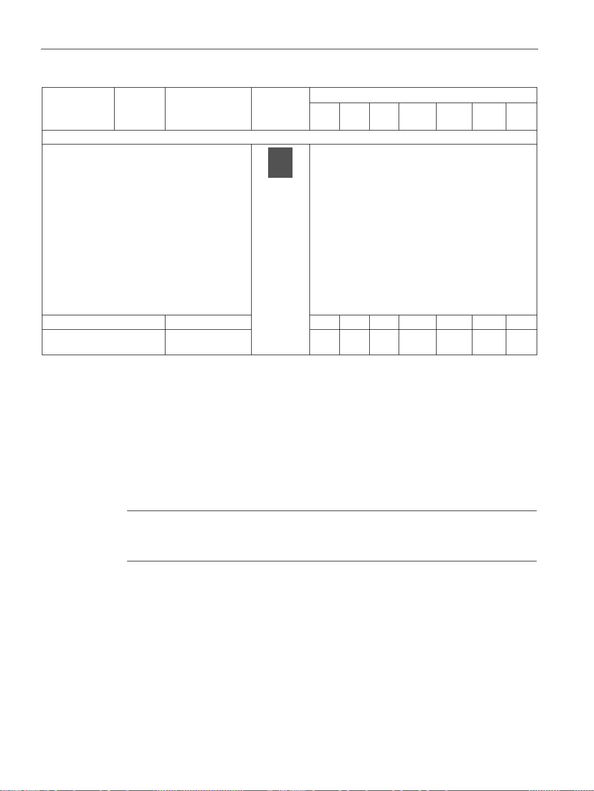
An overview of system components
Module
Control
supply
voltage
MLFB
Diagram
Number that can be connected to
pro C
pro S
V PN
GP
pro V
PB
pro V
MR
pro V
PN
pro V
EIP
Multifunction module
AC/DC
Note
Use of a DM-F instead of a DM
You can use a fail
To expand
• the number of inputs and outputs
• the functional scope
the SIMOCODE pro S basic units.
The following inputs and outputs are available:
• 4 digital inputs
• 2 relay outputs
• 1 input for connecting an analog temperature
sensor (sensor types: PT100/PT1000,
KTY83/KTY84 or NTC)
• 1 input for connecting a 3UL23 residual current
transformer
Input voltage 24 V DC 3UF7600-1AB01-0 — 1 — — — — —
Input voltage 110-240 V
3UF7600-1AU00-0 — 1 — — — — —
1) Not needed when using the 2nd generation current/voltage measuring modules (UM+)
Detailed description: See Description of system components (Page 81)
Dimension drawings: See CAx data, dimension drawings (Page 369)
Mounting instructions See Mounting (Page 185)
Configuration information for SIMOCODE pro V PB when using an operator panel with
display and/or a decoupling module: See Chapter Configuration information for
SIMOCODE pro V when using an older basic unit (Page 155) and Configuration notes for
use of a SIMOCODE pro V MR and SIMOCODE pro V EIP basic unit (Page 158).
2)
3) Only one temperature sensor can be connected
SIMOCODE pro
74 System Manual, 05/2019, A5E40507475002A/RS-AD/004
-safe digital module (DM-FL or DM-FP) instead of a digital module (DM).
Page 75

An overview of system components
Note
Usage restrictions concerning the operator panel with display
•
•
•
*E09* or higher is required
•
•
– 3UF7210-1BA01-0: ≥ E03
4)
SIMOCODE pro V PB basic unit: The operator panel with display can only be used with
SIMOCODE pro V PB basic unit from version *E03*.
SIMOCODE pro V PN, pro V EIP basic unit: An operator panel with display from version
*E07* is required for use with these basic units.
In combination with the SIMOCODE pro PN basic unit, version
when using the operator panel with the 3UF7210-1AA00-0 display.
In combination with the SIMOCODE pro MR basic unit, version *E09* or higher is
required when using the operator panel with the 3UF7210-1AA00-0 display.
When using the "Dry-running protection by means of active power monitoring" function,
the following operator panels with display are permitted:
– 3UF7210-1AA00-0: ≥ E12
– 3UF7210-1AA01-0: ≥ E03
– 3UF7210-1BA00-0: ≥ E04
SIMOCODE pro
System Manual, 05/2019, A5E40507475002A/RS-AD/004
75
Page 76

An overview of system components
System component,
accessory
MLFB
Diagram
for
pro C
for
pro S
for V
PN GP
for pro
V PB
for
pro V MB
RTU
for
pro V
PN
for
pro V
EIP
Connecting cable
decoupling module
2.5 m round
Interface covers
0B (titanium gray)
Memory module
without PC.
Initialization module
control centers.
Y connecting cable
initialization module
Accessories
Selection and ordering data: See also Catalog IC10 (https://www.siemens.com/ic10).
Table 7- 2 System components, accessories that can be connected
for connecting the basic unit, current
measuring module, current/voltage
measuring module, operator panel, and
0.025 m ribbon
0.1 m ribbon
0.15 m ribbon
0.3 m ribbon
0.5 m ribbon
0.5 m round
1.0 m round
1.5 m round
For covering unused
system interfaces
Backup of the full set of
parameters of a
SIMOCODE pro
system when the
device is replaced. If a
device is replaced,
parameter transfer
3UF7930-0AA00-0
3UF7931-0AA00-0
3UF7935-0AA00-0
3UF7932-0AA00-0
3UF7932-0BA00-0
3UF7937-0BA00-0
.........
3UF7933-0BA00-0
3UF7950-0AA00-0
(light gray)
3RA6936-
3UF7900-0AA00-0
(light gray)
3UF7900-0AA01-0
(titanium gray)
3UF7901-0AA00-0
(light gray)
3UF7901-0AA01-0
(titanium gray)
✓ ✓ ✓ ✓ ✓ ✓ ✓
✓ ✓ ✓ ✓ ✓ ✓ ✓
✓
✓
—
—
✓
✓
✓
✓
✓
✓
✓
✓
✓
✓
✓
✓
1)
1)
✓
✓
✓
✓
—
—
✓
✓
—
—
✓
✓
Storage and
initialization of device
parameters and device
addressing in motor
Connection of the basic unit and current or
current/voltage measuring module with the
initialization module when using the
SIMOCODE pro
76 System Manual, 05/2019, A5E40507475002A/RS-AD/004
3UF7902-0AA00-0
— ✓ ✓ ✓ 1) ✓ ✓ ✓
— ✓ ✓ ✓ ✓ ✓ ✓
Page 77
An overview of system components
System component,
accessory
MLFB
Diagram
for
pro C
for
pro S
for V
PN GP
for pro
V PB
for
pro V MB
RTU
for
pro V
PN
for
pro V
EIP
1.0 m
Addressing plug
interface
USB PC cable
PC/PG
USB-to-serial adapter
interface of a PC.
Door adapter
cabinet
Adapter for operator
panel
protection: IP54.
Length of
system
interface
0.1 m
0.5 m
1.0 m
Assigning the
PROFIBUS/
Modbus RTU address
without using a PC/PG
to SIMOCODE pro
through the system
for connecting
SIMOCODE pro to the
USB interface of a
For connecting an
RS 232 PC cable to the
Length
of open
cable
end
1.0 m
1.0 m
3UF7931-0CA00-0
3UF7932-0CA00-0
3UF7937-0CA00-0
3UF7910-0AA00-0
3UF7941-0AA00-A
3UF7946-0AA0-0 ✓ ✓ ✓ ✓ ✓ ✓ ✓
✓ ✓ ✓ ✓ ✓ — —
✓ ✓ ✓ ✓ ✓ ✓ ✓
for bringing out the
system interface, for
example, out of a
Enables use of the
smaller operator
panel (OP) after system
replacement in a front
panel cutout in which a
larger 3UF5 2 operator
panel of
SIMOCODE DP had
previously been used.
Degree of
3UF7920-0AA00-0
3UF7922-0AA00-0
✓ ✓ ✓ ✓ ✓ ✓ ✓
✓ ✓ ✓ ✓ ✓ ✓ ✓
SIMOCODE pro
System Manual, 05/2019, A5E40507475002A/RS-AD/004
77
Page 78

An overview of system components
System component,
accessory
MLFB
Diagram
for
pro C
for
pro S
for V
PN GP
for pro
V PB
for
pro V MB
RTU
for
pro V
PN
for
pro V
EIP
Labeling strips
operator panel 3UF7 20
Push-in lugs for screw
mounting
device
and 3UF7 1.2
3UF7 7
3UF7600-1A.01-0
Terminal covers
Covers for cable lug
and busbar
connections:
3UF7 1.4-1BA00-0
Covers for box
terminals:
3UF7 1.4-1BA00-0
for pushbuttons of the
operator panel 3UF7 20
for pushbuttons of the
operator panel with
display 3UF7 21
for LEDs of the
e.g. on mounting plate;
2 units required per
Can be used for the
current measuring
modules and
current/voltage
measuring modules
3UF7 1.0, 3UF7 1.1
Can be
used for 3UF700,
3UF701, 3UF7 3,
3UF7 4, 3UF7 5 and
3UF7925-0AA00-0
3UF7925-0AA01-0
3UF7925-0AA02-0
3RV2928-0B ✓ ✓ ✓ — ✓ ✓ ✓
3RP19 03 ✓ — — ✓ ✓ ✓ ✓
✓ ✓ ✓ ✓ ✓ ✓ ✓
Can be used for
3UF7020-1A.01-0 and
Length 100 mm, can be
used for
3UF7 1.3-1BA00-0
Length 120 mm, can be
used for
Length 25 mm, can be
used for
3UF7 1.3-1BA00-0
Length 30 mm, can be
used for
3ZY1311-0AA00 — ✓ ✓ — — — —
3RT1956-4EA1
3RT1966-4EA1
3RT1956-4EA2
3RT1966-4EA2
✓ ✓ ✓ ✓ ✓ ✓ ✓
✓ ✓ ✓ ✓ ✓ ✓ ✓
SIMOCODE pro
78 System Manual, 05/2019, A5E40507475002A/RS-AD/004
Page 79

An overview of system components
System component,
accessory
MLFB
Diagram
for
pro C
for
pro S
for V
PN GP
for pro
V PB
for
pro V MB
RTU
for
pro V
PN
for
pro V
EIP
Covers for screwed
connection:
3UF7 1.4-1BA00-0
Box terminal blocks
3UF7 1.4-1BA00-0
Bus termination module
Note
SIMOCODE pro S.
Bus connecting
terminal
between contactor and
current measuring
module or
between
current/voltage
measuring module with
direct mounting
can be used for
3UF7 1.3-1BA00-0
can be used for
for round and ribbon
cable conductors
up to 70 mm2, can be
used for
3UF7 1.3-1BA00-0
up to 120 mm2, can be
used for
3UF7 1.3-1BA00-0
up to 240 mm2, can be
used for
3RT1956-4EA3
3RT1966-4EA3
3RT1955-4G
3RT1956-4G
3RT1966-4G
✓ ✓ ✓ ✓ ✓ ✓ ✓
✓ ✓ ✓ ✓ ✓ ✓ ✓
with dedicated power
supply;
for bus connection after
the last device on the
bus
Supply voltage:
115/230 V AC
24 V DC
The use of bus
connection modules is
recommended, in
particular, when using
For securing the
PROFIBUS cable on
the SIMOCODE pro S
basic unit.
SIMOCODE pro
System Manual, 05/2019, A5E40507475002A/RS-AD/004
3UF1900-1KA00
3UF1900-1KB00
3UF7960-0AA00-0 — ✓ ✓ — — — —
✓ ✓ ✓ ✓ ✓ ✓ ✓
1) For basic unit SIMOCODE pro V PB from version *E09*
79
Page 80

An overview of system components
Software
For parameterization, control, diagnostics and testing: See Manual Parameterizing
SIMOCODE pro (https://support.industry.siemens.com/cs/ww/en/view/109743958
Selection and ordering data: See also Catalog IC10 (https://www.siemens.com/ic10).
).
SIMOCODE pro
80 System Manual, 05/2019, A5E40507475002A/RS-AD/004
Page 81
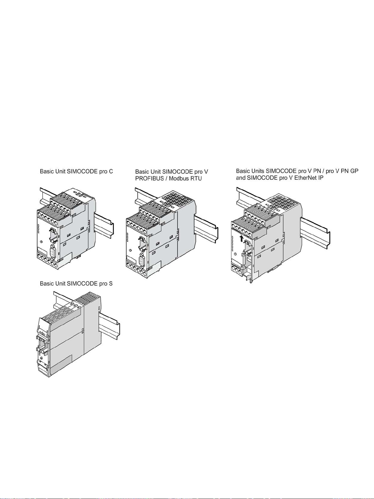
8
8.1 Basic units (BU)
Types of basic units
The basic units are the fundamental components of the SIMOCODE pro system. Basic units
are always necessary when using SIMOCODE pro. They contain the processor in which all
protection, control and monitoring functions of the SIMOCODE system are executed.
Figure 8-1 Basic units
The basic units are suitable for DIN rail mounting or with additional push-in lugs for mounting
on a mounting plate. They are always equipped with removable terminals.
The basic units are available in different types for the following supply voltages:
● 24 V DC
● 110 to 240 V AC / DC
SIMOCODE pro
System Manual, 05/2019, A5E40507475002A/RS-AD/004
81
Page 82

Description of system components
8.1 Basic units (BU)
SIMOCODE pro C basic unit
Basic unit pro C is the fundamental component of the SIMOCODE pro C device series and is
used in conjunction with a current measuring module and optional operator panels.
The following motor control functions are supported:
● Overload relay
● Direct starter (direct-on-line starter) and reversing starter
● Circuit breaker control (MCCB).
SIMOCODE pro S basic unit
Basic unit pro S is the fundamental component of the SIMOCODE pro S device series and is
used in conjunction with a current measuring module and an optional operator panel. As
compared with the basic unit, SIMOCODE pro C provides the following expansion options by
means of connecting a multifunction / expansion module:
● Increased device functionality with additional inputs and outputs
● Connection of a residual current transformer
● Connection of a temperature sensor.
The following motor control functions are supported:
● Overload relay
● Direct starter (direct-on-line starter) and reversing starter
● Star-delta starter
● Circuit breaker control (MCCB)
● Control of a soft starter.
SIMOCODE pro
82 System Manual, 05/2019, A5E40507475002A/RS-AD/004
Page 83

Description of system components
8.1 Basic units (BU)
SIMOCODE pro V PN GP basic unit
The SIMOCODE pro V PN GP General Performance basic unit for PROFINET is used in
combination with a current measuring module and an optional operator panel. It provides the
following expansion options by means of connecting an expansion module:
● Increased device functionality with additional inputs and outputs
● Connection of a residual current transformer
● Connection of a temperature sensor.
The following motor control functions are supported:
● Overload relay
● Direct starter (direct-on-line starter) and reversing starter
● Star-delta starter
● Circuit breaker control (MCCB)
● Control of a soft starter.
SIMOCODE pro V High Performance basic unit
The SIMOCODE pro V High Performance basic units are the fundamental components of
the SIMOCODE pro V device series and are used in combination with a current measuring
module or current / voltage measuring module and optional operator panel.
The following motor control functions are supported:
● Overload relay
● Direct starter (direct-on-line starter) and reversing starter
● Star-delta starter, possibly combined with reversing starter
● 2 speeds, motors with separate windings (pole-changing starters), possibly combined
with reversing starter
● 2 speeds, motors with separate Dahlander windings, possibly combined with reversing
starter
● Positioner control
● Solenoid valve control
● Circuit breaker control (MCCB)
● Soft starter control, possibly combined with reversing starter
The SIMOCODE pro V High Performance basic units provide the following expansion
options not offered by the SIMOCODE pro C, SIMOCODE pro S and
SIMOCODE PRO V PN GP basic units:
● Increased device functionality via various expansion modules according to need
● Use of a current / voltage measuring module in place of a current measuring module
● Additional inputs and outputs, as required
● Larger number of inputs and outputs
● Use of an operator panel with display in place of a standard operator panel.
SIMOCODE pro
System Manual, 05/2019, A5E40507475002A/RS-AD/004
83
Page 84

Description of system components
8.1 Basic units (BU)
Operator controls and display elements, system interfaces basic units
LEDs for device diagnostics (DEVICE, BUS, GEN. FAULT)
These LEDs on the front of the device are used for device and fault diagnostics, and indicate
the basic status:
● Of the device itself via the "DEVICE" LED
● For bus communication via the "BUS" LED
● By displaying the activity at the two ports via the LEDs "PORT 1" and "PORT 2"
● Of any motor feeder faults via the "GEN. FAULT" FAULT" LED
For further information, refer to Chapters Diagnostics via LED display on the basic unit and
on the operator panel (PROFIBUS) (Page 259) and Diagnostics via LED display on the basic
unit and on the operator panel (PROFINET) (Page 264).
"TEST/RESET" button
Enables the device to be reset after tripping or after a fault has occurred and makes it
possible to test the device/motor feeder with or without tripping the contactor control. If a
memory module or addressing plug is plugged in, parameterization can be initiated via the
TEST/RESET button or, for example, by accepting the PROFIBUS address.
You will find further information in Chapter "Test/Reset" in the manual Parameterizing
SIMOCODE pro (https://support.industry.siemens.com/cs/ww/en/view/109743958
Chapters Setting the PROFIBUS DP address (Page 258) and Setting IP parameters and
PROFINET device name (Page 261) and in Chapter Backing up and saving parameters
(Page 277).
System interfaces
2 system interfaces for connecting
● a current measuring module or a current / voltage measuring module and
● an operator panel or expansion modules
), in
SIMOCODE pro
84 System Manual, 05/2019, A5E40507475002A/RS-AD/004
Page 85
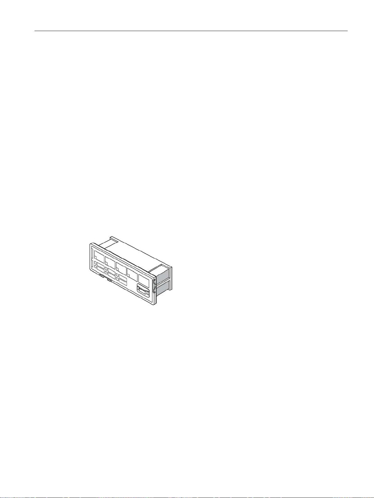
Description of system components
8.2 Operator panel (OP)
8.2 Operator panel (OP)
Function of the operator panel
The operator panel controls the motor feeder from the switchgear cabinet. It has an external
system interface on the front to allow easier parameterization or diagnostics via a
PC / programming device. This system interface (with cover for IP54) can be used to
connect (by means of the PC cable) a PC with the SIMOCODE ES (TIA Portal) software
installed or the memory module or the addressing plug.
On the rear system interface, it is connected to the basic unit or to an expansion module via
a connecting cable. It is supplied with power via the basic unit.
The operator panel is frequently installed in the front panels of motor control centers. It is
used in all device series. It also contains all the status LEDs available on the basic unit and
the "TEST/RESET" button, and facilitates access to the system interface from outside the
control cabinet.
The following are available:
● 5 buttons, of which 4 are freely parameterizable
● 10 LEDs, of which 7 are freely parameterizable
The following figure shows an operator panel:
Figure 8-2 Operator panel
SIMOCODE pro
System Manual, 05/2019, A5E40507475002A/RS-AD/004
85
Page 86
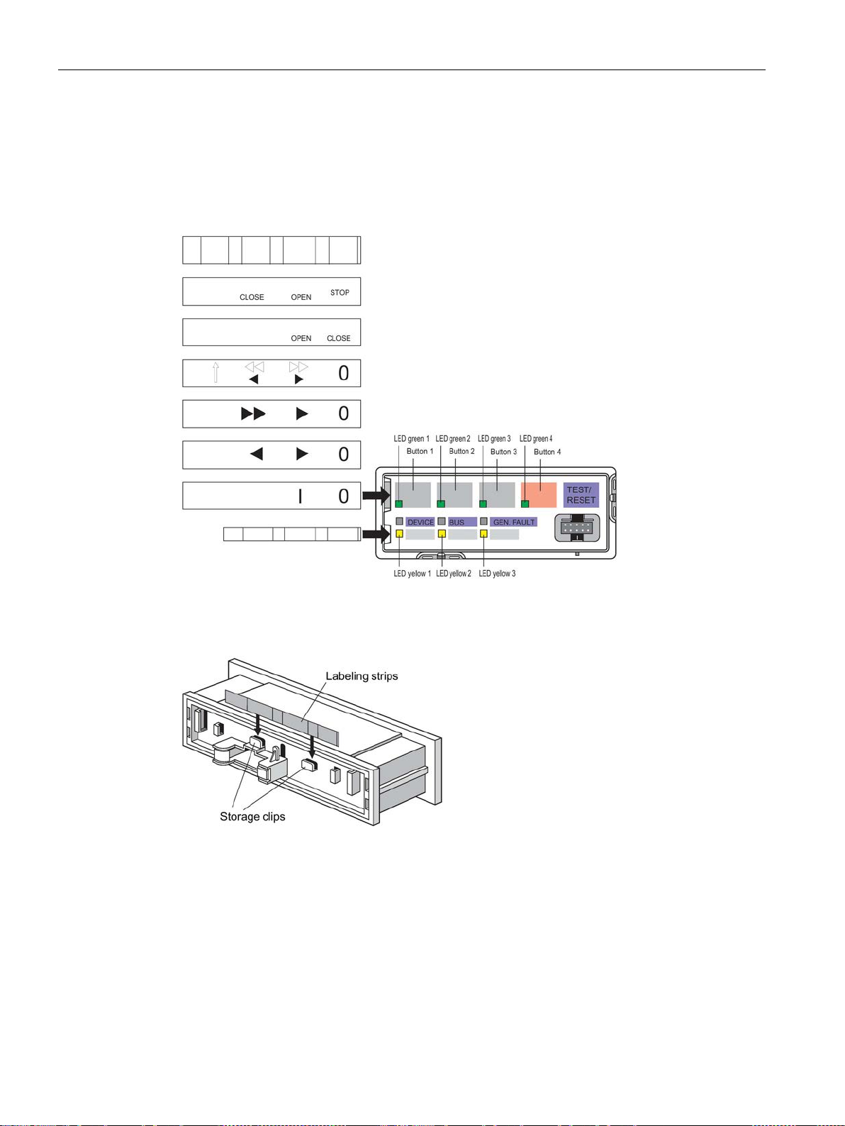
Description of system components
8.2 Operator panel (OP)
Labeling strips:
Labeling strips are enclosed for designating buttons 1 to 4 and the yellow LEDs 1 to 3:
● Buttons 1 to 4: 6 pre-assigned labeling strips and 1 individually inscribable labeling strip
● LEDs 1 to 3: 1 individually inscribable labeling strip
Figure 8-3 Labeling strips for operator panel buttons and LEDs
Unused labeling strips can be stored on the back of the operator panel:
Figure 8-4 Storage clips for labeling strips for pushbuttons and LEDs of the operator panel
SIMOCODE pro
86 System Manual, 05/2019, A5E40507475002A/RS-AD/004
Page 87
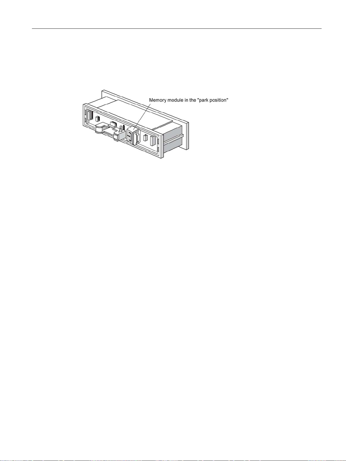
Description of system components
8.2 Operator panel (OP)
"Park position" for memory module:
The memory module can be protected from unauthorized use by "parking" it on the rear of
the operator panel inside the switchgear cabinet. In this case, the storage clips for the
labeling strips cannot be used.
Figure 8-5 "Park position" for memory module
SIMOCODE pro
System Manual, 05/2019, A5E40507475002A/RS-AD/004
87
Page 88

Description of system components
Note
Usage restrictions concerning the operator panel with display
•
•
•
equired
•
•
– 3UF7210-1BA01-0: ≥ E03
8.3 Operator panel with display
8.3 Operator panel with display
8.3.1 Description of the operator panel with display
Apart from the standard operator panel (OP), an optional operator panel with display (OPD)
is also available for the SIMOCODE pro V High Performance device series. This operator
panel can additionally display current measured values, operating data, diagnostics data or
status information of the motor feeder on the cabinet. It also contains all the status LEDs that
are present on the basic unit and facilitates access to the system interface from outside the
cabinet. The motor can be controlled via the buttons on the operator panel. Current
measured values, status information, fault messages or the device-internal error log are
simultaneously shown on the display.
SIMOCODE pro V PB basic unit: The operator panel with display can only be used with
SIMOCODE pro V PB basic unit from version *E03*.
SIMOCODE pro V PN, pro V EIP basic unit: An operator panel with display from version
*E07* is required for use with these basic units.
In combination with the SIMOCODE pro PN basic unit, version *E09* or higher is r
when using the operator panel with the 3UF7210-1AA00-0 display.
In combination with the SIMOCODE pro MR basic unit, version *E09* or higher is
required when using the operator panel with the 3UF7210-1AA00-0 display.
When using the "Dry-running protection by means of active power monitoring" function,
the following operator panels with display are necessary:
– 3UF7210-1AA00-0: ≥ E12
– 3UF7210-1AA01-0: ≥ E03
– 3UF7210-1BA00-0: ≥ E04
The following are available:
● 4 freely parameterizable buttons for controlling the motor feeder
● 4 keys for navigating the display menu, 2 of these are softkeys with different functions
(e g. test / reset)
● 2 system interfaces (front and back)
● 7 LEDs, 4 of which are freely parameterizable (4 green LEDs integrated in the motor
control buttons, primarily for feedback regarding the switching state, e.g. ON, OFF, CCW,
CW, etc.)
SIMOCODE pro
88 System Manual, 05/2019, A5E40507475002A/RS-AD/004
Page 89

Description of system components
Note
Modification of selected device parameters via the operator panel with display
Modification of selected device parameters is possible via the operator panel with display
(
NOTICE
Active operation
Note
When using an operator panel with display, you may have to consider restrictions in the type
and number of expansion modules that can be connected to a basic unit!
See Chapter
(Page
8.3 Operator panel with display
see Parameters (Page 124))
The following figure shows an operator panel with display:
Figure 8-6 Operator panel with display
The operator panel with display can be connected directly to basic unit SIMOCODE pro V or
an expansion module via the rear system interface. Voltage is supplied by the basic unit.
This front system interface (with cover for IP54) can be used to connect (by means of the PC
cable) a PC with the SIMOCODE ES (TIA Portal) software installed or the memory module
and the addressing plug.
You must not remove or plug in the operator panel with display during operation!
Configuration information for SIMOCODE pro V when using an older basic unit
155).
SIMOCODE pro
System Manual, 05/2019, A5E40507475002A/RS-AD/004
89
Page 90
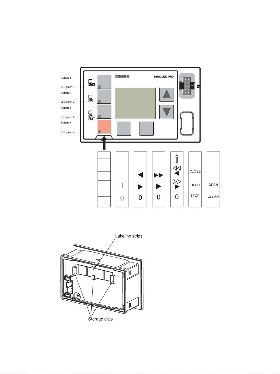
Description of system components
8.3 Operator panel with display
Labeling strips:
Labeling strips for labeling buttons 1 to 4 (6 pre-assigned and 1 that can be labeled
individually) are included:
Figure 8-7 Labeling strips for the buttons of the operator panel with display
Unused labeling strips can be stored on the back of the operator panel with display:
Figure 8-8 Storage clips for labeling strips
SIMOCODE pro
90 System Manual, 05/2019, A5E40507475002A/RS-AD/004
Page 91
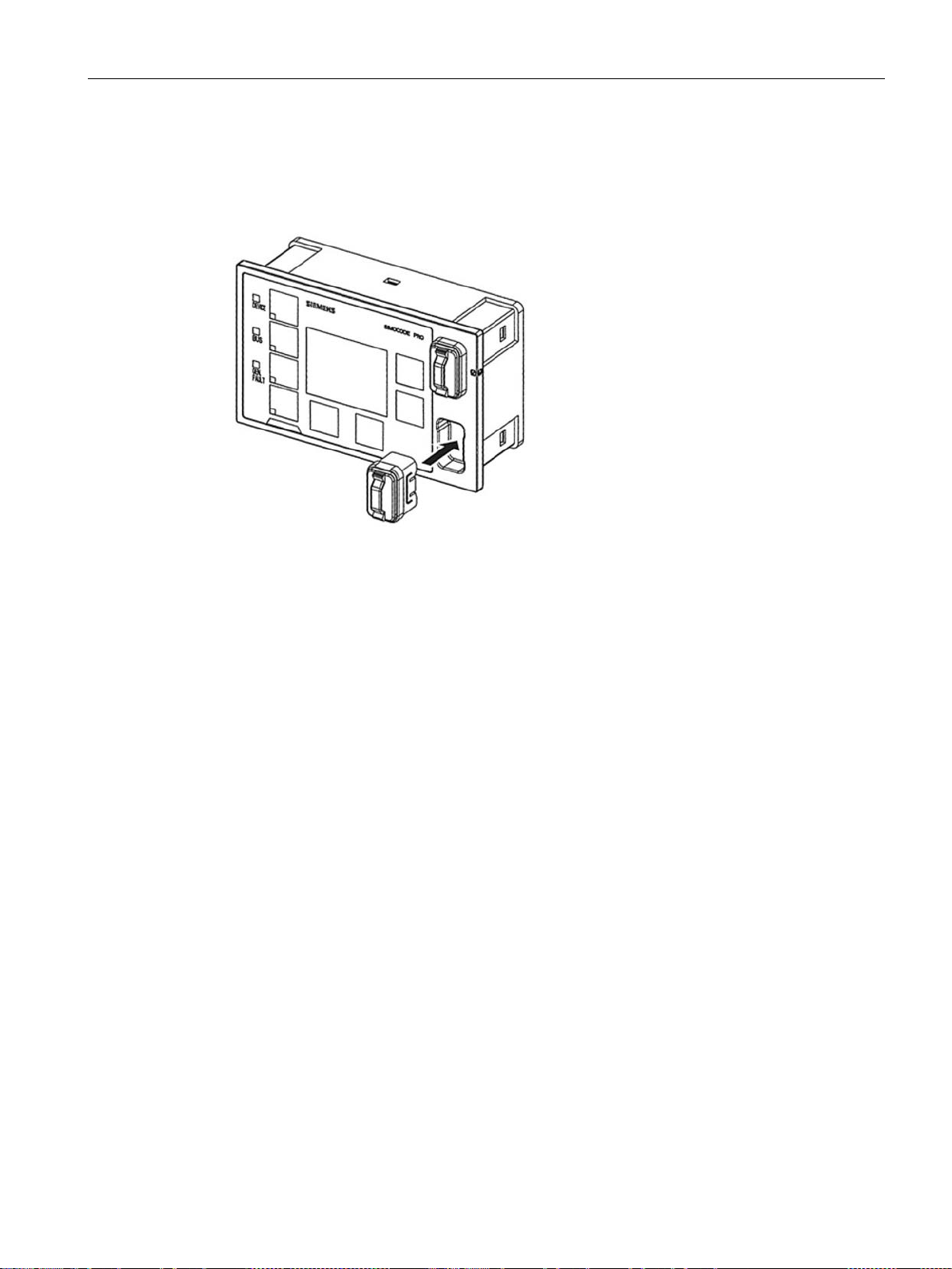
Description of system components
8.3 Operator panel with display
"Park position" for memory module:
The memory module can be "parked" on the front of the operator panel with display beneath
the system interface:
Figure 8-9 "Park position" for memory module
SIMOCODE pro
System Manual, 05/2019, A5E40507475002A/RS-AD/004
91
Page 92
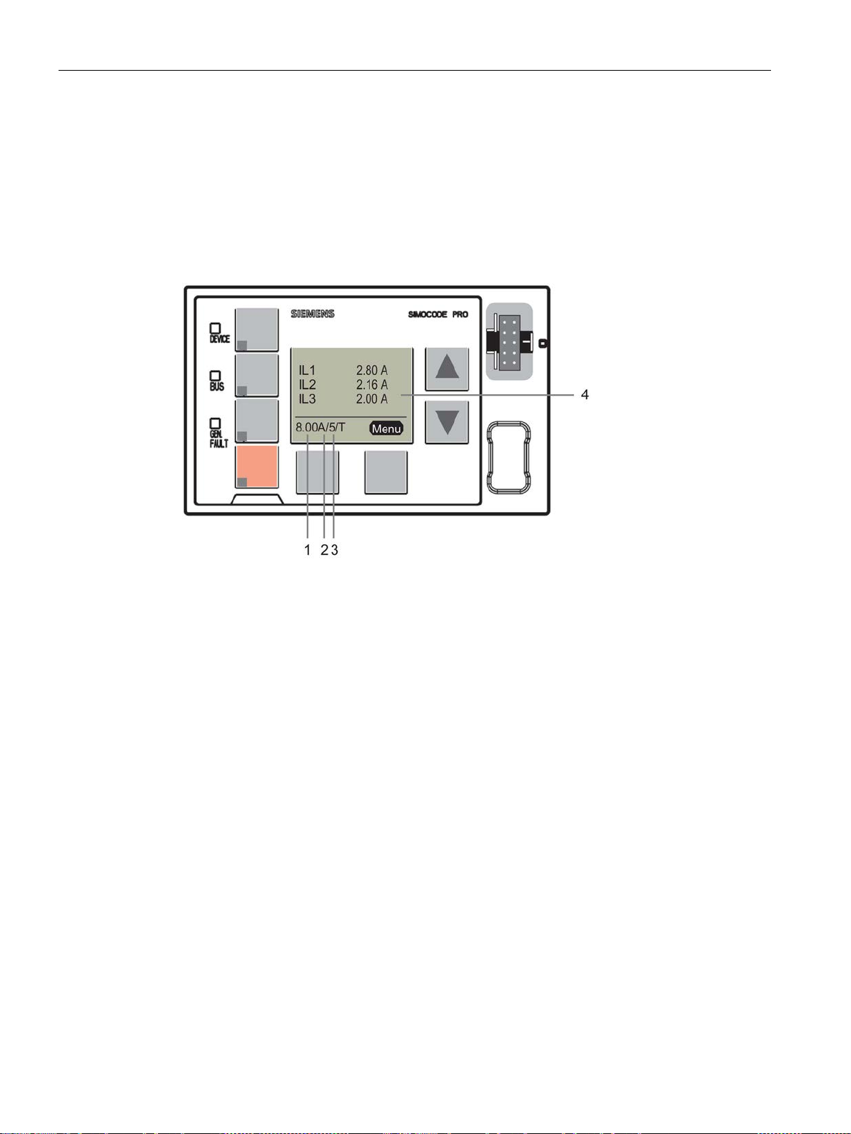
Description of system components
8.3 Operator panel with display
8.3.2 Operator controls and display elements of the operator panel with display
Displays of the operator panel with display
The display shows current measured values, operating data and diagnostics data as well as
the status information of the motor feeder in plain text or with the aid of symbols.
Figure 8-10 Display elements of the operator panel with display
1
Shows the current setting Is / rated motor current in A. For motors with two speeds, the
relevant current setting Is1 or Is2 is always displayed depending on whether the current
speed is slow or fast, e.g.
used when the motor is stopped to alternate between the display of the two current settings.
When running, the current setting for the active motor speed is always displayed.
2
Shows the set class time of the overload protection system, e.g.:10 = class 10
(class = trip class)
3
Indicates that temperature monitoring is active, e.g. the motor temperature is being
monitored by thermistors or analog temperature sensors (Pt100, Pt1000, KTY, NTC).
T= temperature monitoring active.)
(
4
The main display enables customized depiction of different measured values when running.
This is the standard display at the topmost menu level. Predefined profiles in the display
settings can be selected for this purpose. By pressing the "Menu" softkey on the right, you
can navigate through the submenus of the main display (see Chapter
display (Page 112)).
8 A. For motors with two speeds, the left-hand softkey can be
Read and adapt main
SIMOCODE pro
92 System Manual, 05/2019, A5E40507475002A/RS-AD/004
Page 93
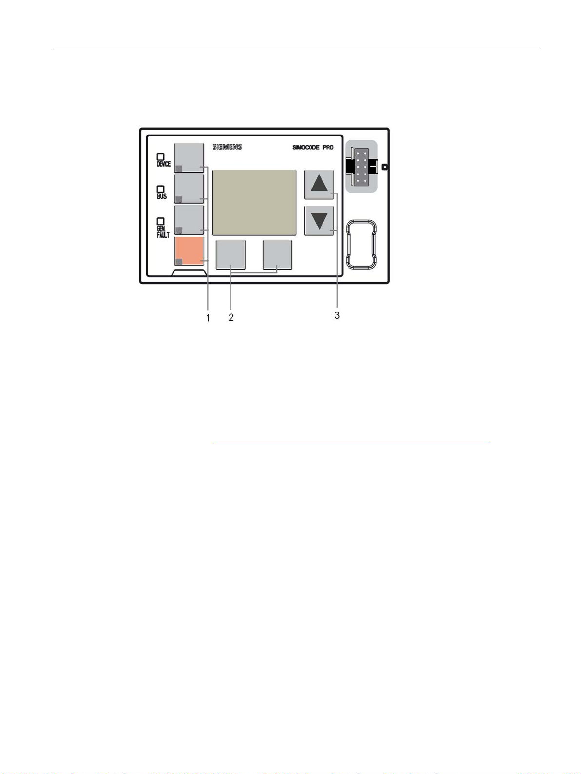
Description of system components
8.3 Operator panel with display
Operator controls of the operator panel with display
Figure 8-11 Operator controls of the operator panel with display
1
Four freely parameterizable operator keys with status LED. These operator keys are used to
control the motor with integrated status LEDs for any status feedback. The functions can be
user-defined. Labeling can be either freely chosen or achieved using the labeling strips
supplied with the device (see also Chapter
Operator panel with display (Page 88) and
Chapters "Operator panel LED" and "Operator panel buttons" in the manual Parameterizing
SIMOCODE pro (https://support.industry.siemens.com/cs/ww/en/view/109743958
))
2
Two softkeys. They can have different functions depending on the menu displayed
(e.g. open menu, exit menu, TEST/RESET). The currently assigned functions are shown on
the lower left or right edge of the display.
3
Two arrow keys (one upwards arrow and one downwards arrow). They serve to navigate the
menu or change the display settings, e.g. to adjust the contrast or to select a profile for the
main display.
SIMOCODE pro
System Manual, 05/2019, A5E40507475002A/RS-AD/004
93
Page 94
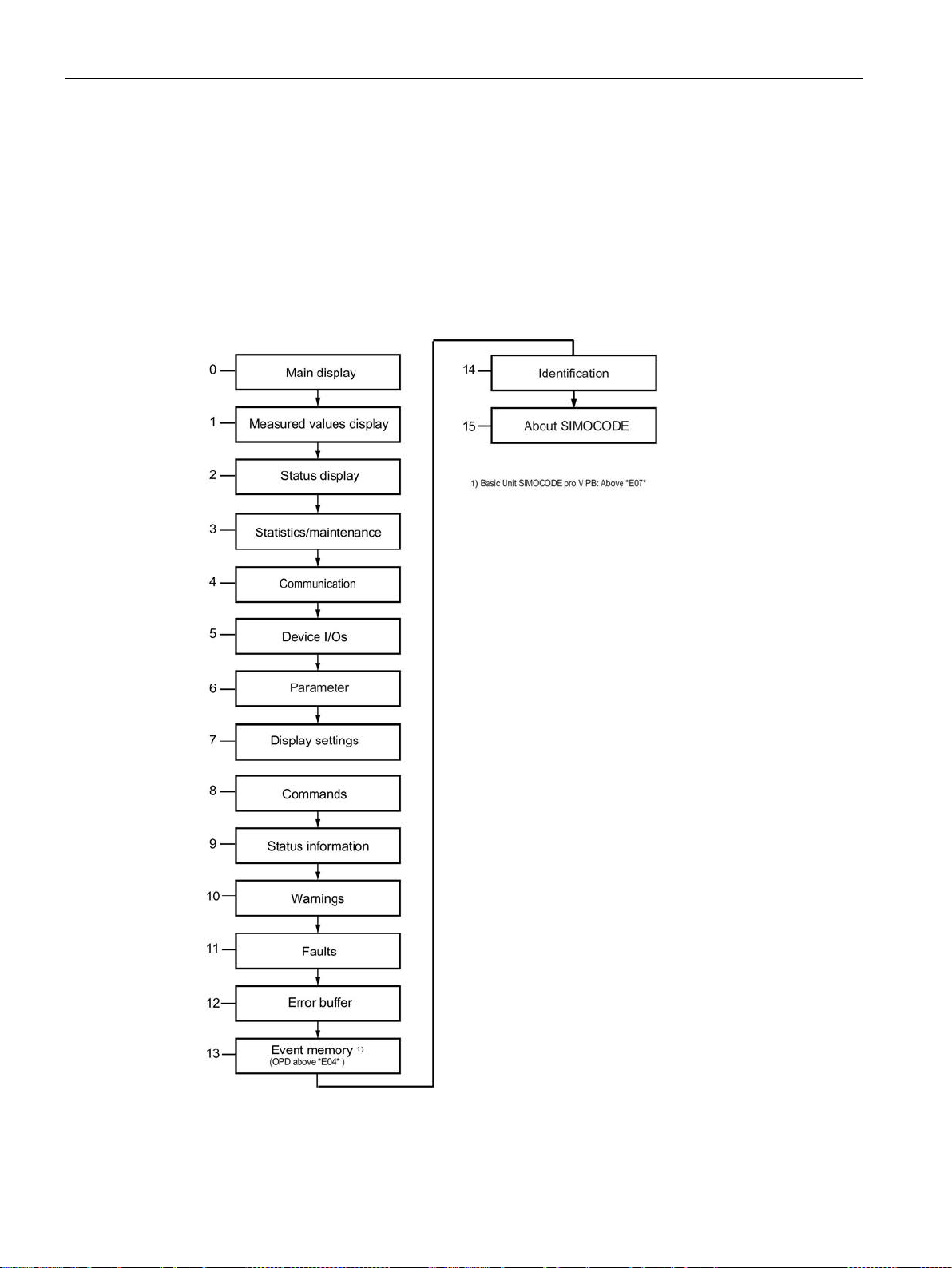
Description of system components
8.3 Operator panel with display
8.3.3 Menu of the operator panel with display
8.3.3.1 Timing charts
Navigating the menu of the operator panel with display
Main menu, operator panel with display
Details: See Displays of the operator panel with display (Page 109).
Figure 8-12 Main menu, operator panel with display
SIMOCODE pro
94 System Manual, 05/2019, A5E40507475002A/RS-AD/004
Page 95
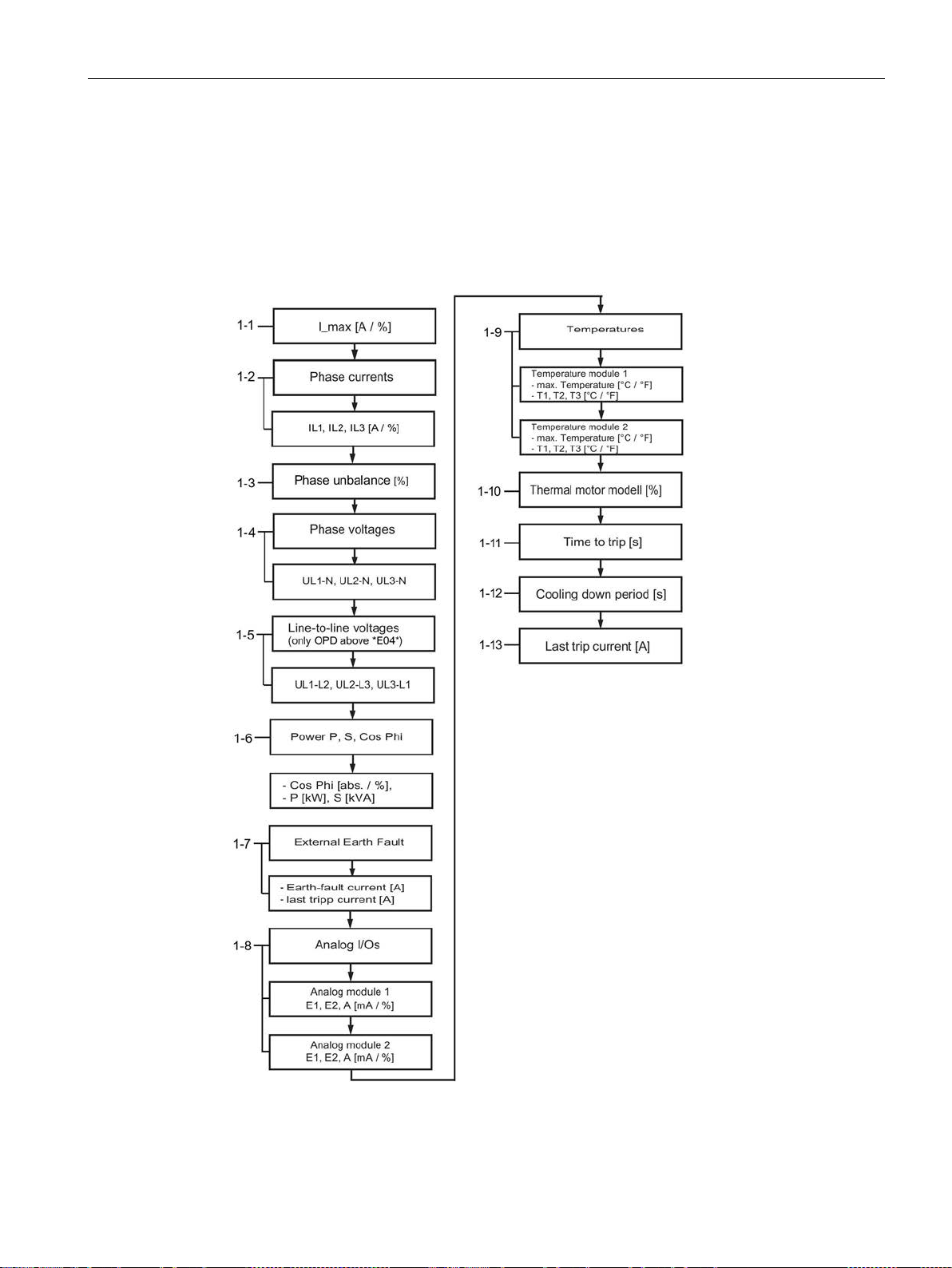
Description of system components
8.3 Operator panel with display
Main display, operator panel with display
Details: See Read and adapt main display (Page 112).
1 Measured values, operator panel with display
Details: See Display of measured values in the measured values display (Page 115).
Figure 8-13 Measured values, operator panel with display
SIMOCODE pro
System Manual, 05/2019, A5E40507475002A/RS-AD/004
95
Page 96
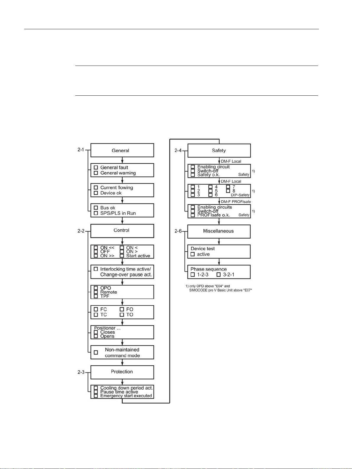
Description of system components
Note
Numbering of the displays
The numbering is valid with the maximum
8.3 Operator panel with display
expansion.
2 Status motor protection/motor control, operator panel with display
Details: See Motor protection and motor control status (Page 117).
Figure 8-14 Status motor protection/motor control, operator panel with display -
SIMOCODE pro
96 System Manual, 05/2019, A5E40507475002A/RS-AD/004
PROFIBUS / Modbus RTU
Page 97
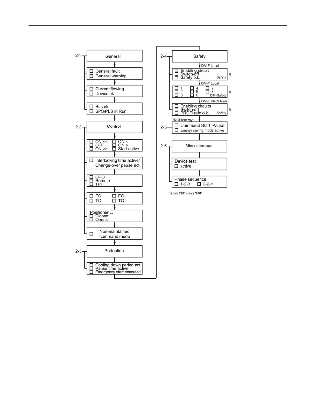
Description of system components
8.3 Operator panel with display
Figure 8-15 Status motor protection/motor control, operator panel with display -
PROFINET / EtherNet/IP
SIMOCODE pro
System Manual, 05/2019, A5E40507475002A/RS-AD/004
97
Page 98
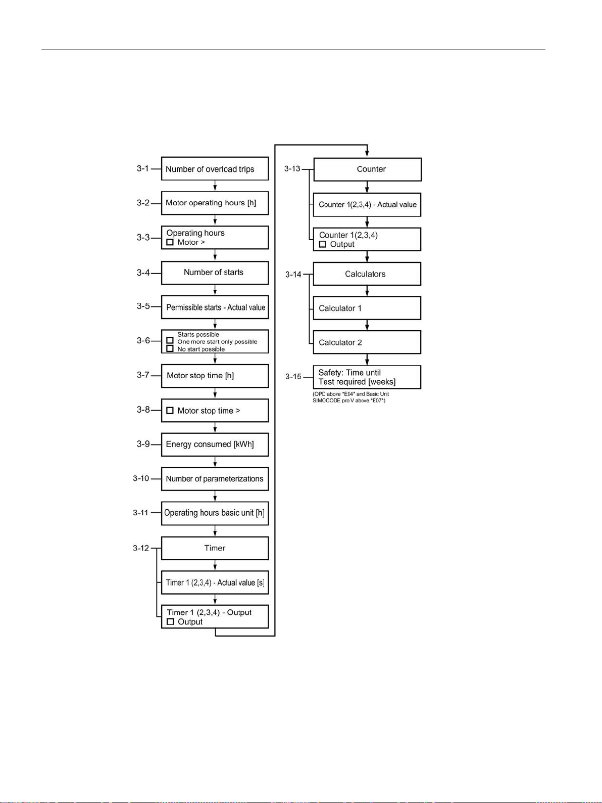
Description of system components
8.3 Operator panel with display
3 Statistics/maintenance, operator panel with display
Details: See Display of statistical and maintenance-relevant information on the
statistics/maintenance display (Page 119).
Figure 8-16 Statistics/maintenance, operator panel with display - PROFIBUS / Modbus
SIMOCODE pro
98 System Manual, 05/2019, A5E40507475002A/RS-AD/004
Page 99
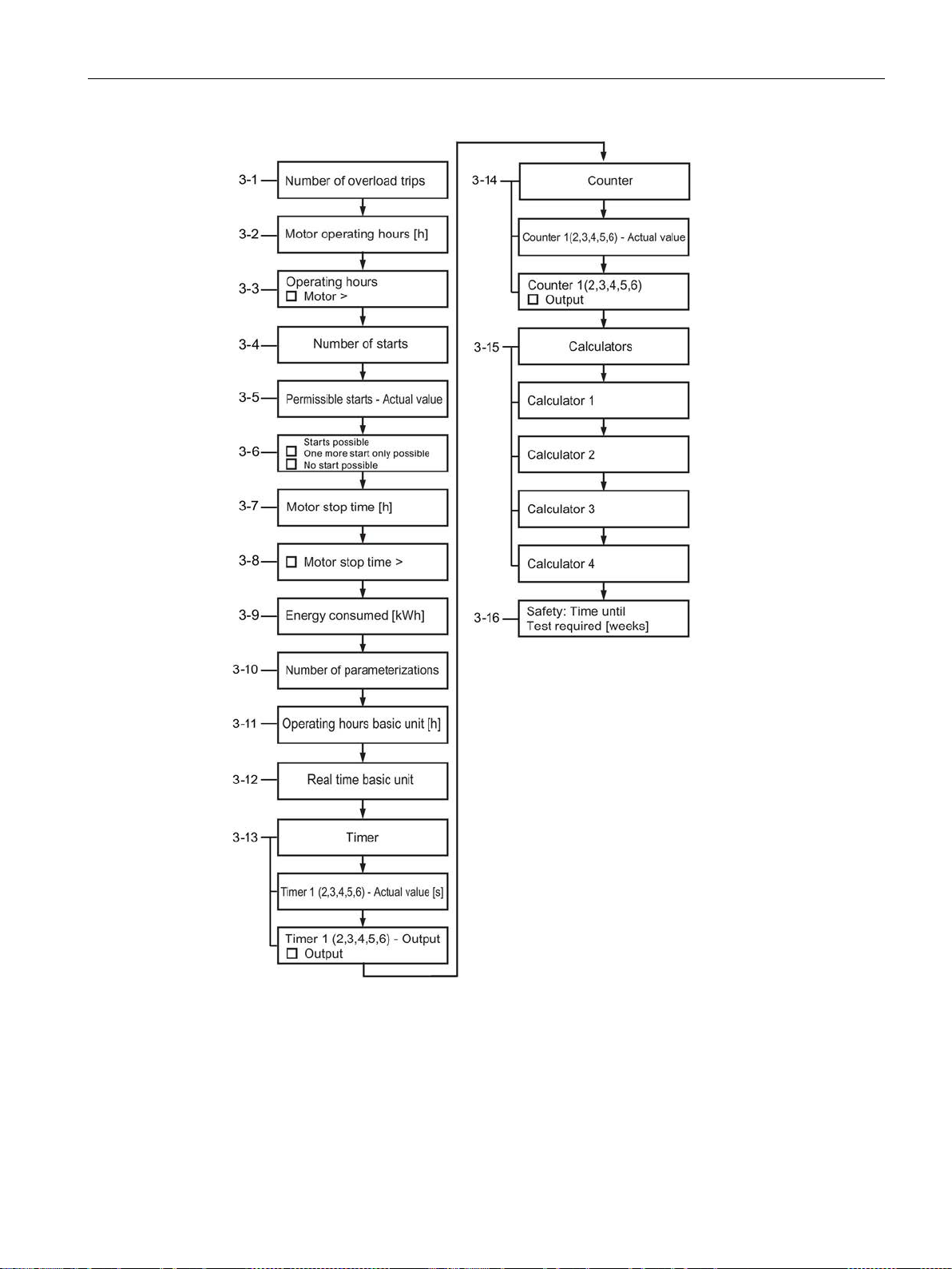
Description of system components
8.3 Operator panel with display
Figure 8-17 Statistics/maintenance, operator panel with display - PROFINET / EtherNet/IP
SIMOCODE pro
System Manual, 05/2019, A5E40507475002A/RS-AD/004
99
Page 100
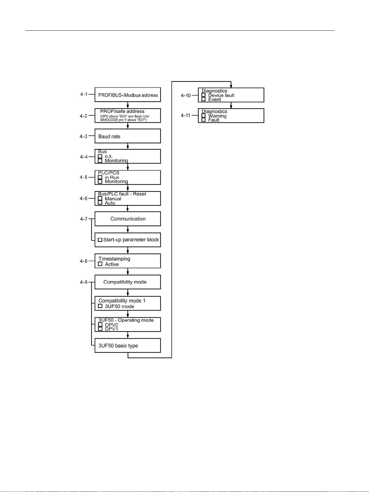
Description of system components
8.3 Operator panel with display
4 Communication on the fieldbus, operator panel with display
Details: See Status display for fieldbus communication (Page 120).
Figure 8-18 Communication on PROFIBUS / Modbus, operator panel with display
SIMOCODE pro
100 System Manual, 05/2019, A5E40507475002A/RS-AD/004
 Loading...