

Page 1
Programming and
Operating Manual
Industrial Controls
Function Block Library SIMOCODE pro
for SIMATIC PCS 7
SIMOCODE pro PCS 7 Library V9.0
Edition
06/2017
siemens.com
Page 2

___________________
___________________
___________________
___________________
___________________
___________________
___________________
___________________
Industrial Controls
SIMOCODE pro
SIMOCODE pro PCS 7 Library V9.0
Programming and Operating Manual
06/2017
A5E40899442002A/RS
Introduction
1
Templates
2
Block icons and faceplate
views
3
Description of the blocks
4
Maintenance Station
5
Parameter
A
Technical Data
B
Abbreviations
C
-AA/001
Page 3
Siemens AG
Division Digital Factory
Postfach 48 48
90026 NÜRNBERG
GERMANY
A5E40899442002A/RS-AA/001
Ⓟ
Copyright © Siemens AG 2017.
All rights reserved
Legal information
Warning notice system
DANGER
indicates that death or severe personal injury will result if proper precautions are not taken.
WARNING
indicates that death or severe personal injury may result if proper precautions are not taken.
CAUTION
indicates that minor personal injury can result if proper precautions are not taken.
NOTICE
indicates that property damage can result if proper precautions are not taken.
Qualified Personnel
personnel qualified
Proper use of Siemens products
WARNING
Siemens products may only be used for the applications described in the catalog and in the relevant technical
ambient conditions must be complied with. The information in the relevant documentation must be observed.
Trademarks
Disclaimer of Liability
This manual contains notices you have to observe in order to ensure your personal safety, as well as to prevent
damage to property. The notices referring to your personal safety are highlighted in the manual by a safety alert
symbol, notices referring only to property damage have no safety alert symbol. These notices shown below are
graded according to the degree of danger.
If more than one degree of danger is present, the warning notice representing the highest degree of danger will
be used. A notice warning of injury to persons with a safety alert symbol may also include a warning relating to
property damage.
The product/system described in this documentation may be operated only by
task in accordance with the relevant documentation, in particular its warning notices and safety instructions.
Qualified personnel are those who, based on their training and experience, are capable of identifying risks and
avoiding potential hazards when working with these products/systems.
Note the following:
for the specific
documentation. If products and components from other manufacturers are used, these must be recommended
or approved by Siemens. Proper transport, storage, installation, assembly, commissioning, operation and
maintenance are required to ensure that the products operate safely and without any problems. The permissible
All names identified by ® are registered trademarks of Siemens AG. The remaining trademarks in this publication
may be trademarks whose use by third parties for their own purposes could violate the rights of the owner.
We have reviewed the contents of this publication to ensure consistency with the hardware and software
described. Since variance cannot be precluded entirely, we cannot guarantee full consistency. However, the
information in this publication is reviewed regularly and any necessary corrections are included in subsequent
editions.
06/2017 Subject to change
Page 4

Table of contents
1 Introduction .............................................................................................................................................. 10
2 Templates ................................................................................................................................................ 38
1.1 Security information ............................................................................................................... 10
1.2 Product specific security information ..................................................................................... 10
1.3 Components of the software package ................................................................................... 11
1.4 Supported control functions ................................................................................................... 12
1.5 Configuration Steps ............................................................................................................... 14
1.5.1 Configuring in HW Config ...................................................................................................... 14
1.5.2 Configuring in CFC ................................................................................................................ 16
1.6 Driver generator ..................................................................................................................... 17
1.6.1 Driver generator ..................................................................................................................... 17
1.6.2 Requirements for generating the module drivers ................................................................... 19
1.6.3 Driver blocks .......................................................................................................................... 20
1.6.4 Object lists and action lists ..................................................................................................... 20
1.7 Example configurations .......................................................................................................... 21
1.7.1 SIMOCODE pro PROFIBUS and PROFINET Configuration ................................................. 21
1.7.2 SIMOCODE pro PROFIBUS configuration ............................................................................ 21
1.7.3 SIMOCODE pro PROFINET configuration ............................................................................ 24
1.8 Parameterization softwares ................................................................................................... 32
1.8.1 Parameterization Softwares ................................................................................................... 32
1.8.2 Configuring in SIMOCODE ES .............................................................................................. 32
1.8.2.1 Parameter settings ................................................................................................................. 34
1.8.3 Configuration with SIMATIC PDM .......................................................................................... 35
1.8.4 Device type selection in HW Config ....................................................................................... 35
1.9 Configuring of the fail-safe, digital PROFIsafe module .......................................................... 36
1.10 Update an existing PCS 7 project .......................................................................................... 37
1.11 Further documentation ........................................................................................................... 37
2.1 Overview of the templates, control functions and blocks ....................................................... 38
2.2 Using templates ..................................................................................................................... 39
2.3 Template OvlRly..................................................................................................................... 42
2.4 Template Direct ...................................................................................................................... 43
2.5 Template Reverse .................................................................................................................. 44
2.6 Template MCCB..................................................................................................................... 45
2.7 Template StarDel ................................................................................................................... 46
2.8 Template RevStarDel ............................................................................................................. 47
2.9 Template Dahland .................................................................................................................. 48
SIMOCODE pro PCS 7 Library V9.0
4 Programming and Operating Manual, 06/2017, A5E40899442002A/RS-AA/001
Page 5

Table of contents
3 Block icons and faceplate views .............................................................................................................. 56
4 Description of the blocks .......................................................................................................................... 72
2.10 Template RevDahl .................................................................................................................. 49
2.11 Template PoleChng ................................................................................................................ 50
2.12 Template RevPoleCh .............................................................................................................. 51
2.13 Template SolValve .................................................................................................................. 52
2.14 Template Positner ................................................................................................................... 53
2.15 Template SoftStr ..................................................................................................................... 54
2.16 Template RevSoftStr............................................................................................................... 55
2.17 Sample Project ........................................................................................................................ 55
3.1 Block icons .............................................................................................................................. 56
3.2 Faceplates .............................................................................................................................. 58
3.2.1 Faceplates - Structure............................................................................................................. 58
3.2.2 Navigation between SIMOCODE pro faceplates .................................................................... 61
3.2.3 Views ...................................................................................................................................... 62
3.2.3.1 Batch view ............................................................................................................................... 62
3.2.3.2 Trend view .............................................................................................................................. 62
3.2.3.3 Alarm view .............................................................................................................................. 64
3.2.3.4 Memo view .............................................................................................................................. 66
3.2.3.5 Preview view ........................................................................................................................... 67
3.2.4 Scalable faceplates ................................................................................................................. 67
3.3 Central color management ..................................................................................................... 69
3.4 Web Navigator ........................................................................................................................ 70
3.5 APL Operator Trend Control (AOTC) for Digital Values ......................................................... 71
4.1 Functions for all blocks ........................................................................................................... 72
4.1.1 Calling OBs ............................................................................................................................. 72
4.1.2 Called blocks ........................................................................................................................... 73
4.1.3 Worst signal status .................................................................................................................. 74
4.1.4 Quality code ............................................................................................................................ 75
4.1.5 Error numbers ......................................................................................................................... 77
4.1.6 Reading and writing data records ........................................................................................... 78
4.1.7 Read Record error status ....................................................................................................... 79
4.1.8 Write Record error status ........................................................................................................ 79
4.1.9 Overview of the measuring point browser window ................................................................. 79
4.1.10 Configurable response using the Feature I/O ......................................................................... 80
4.1.10.1 Start-up characteristics ........................................................................................................... 80
4.1.10.2 Response for Out of service mode ......................................................................................... 81
4.1.10.3 Resets the commands for switching between modes ............................................................ 81
4.1.10.4 Enabling resetting of commands for the control settings ........................................................ 82
4.1.10.5 Setting switch or button mode ................................................................................................ 82
4.1.10.6 Set switching mode ................................................................................................................. 83
4.1.10.7 Enabling direct changeover between forward and reverse .................................................... 83
4.1.10.8 Resetting via input signals in the event of interlocking (Protection) or errors......................... 84
4.1.10.9 Exit local mode ........................................................................................................................ 84
4.1.10.10 Enable runtime for feedback signals ....................................................................................... 84
SIMOCODE pro PCS 7 Library V9.0
Programming and Operating Manual, 06/2017, A5E40899442002A/RS-AA/001
5
Page 6

Table of contents
4.1.10.11 Separate monitoring time for stopping the motor ................................................................... 85
4.1.10.12 Enabling rapid stop via faceplate ........................................................................................... 85
4.1.10.13 Activate bumpless changeover to automatic mode ............................................................... 85
4.1.10.14 Activate fault status for external control system fault ............................................................. 86
4.1.10.15 Reset even in locked state ..................................................................................................... 86
4.1.10.16 Disable Feedback Tracking LocalSetting 2 & 4 ..................................................................... 86
4.1.10.17 Bumpless switchover to automatic mode .............................................................................. 87
4.1.10.18 Update acknowledgement and error status of the alarm ....................................................... 87
4.1.10.19 Activate local operator permission ......................................................................................... 87
4.1.10.20 Suppression of all messages ................................................................................................. 88
4.1.10.21 Interlock display with LocalSetting 2 or 4 ............................................................................... 88
4.1.10.22 Define reset as a function of the mode .................................................................................. 88
4.1.10.23 Enable reset of interlocks in manual mode ............................................................................ 90
4.1.10.24 Suppression of single alarm message ................................................................................... 91
4.1.10.25 Resetting control in case of invalid command ....................................................................... 91
4.1.10.26 Setting switch or button mode for local commands ............................................................... 91
4.1.10.27 Evaluation of the signal status of the interlock signals .......................................................... 92
4.1.10.28 Forcing operating modes in the "Local" mode ....................................................................... 93
4.1.10.29 Considering bad quality of automatic commands or external values .................................... 93
4.1.10.30 Separate interlock for each direction or position .................................................................... 93
4.2 Diagnostics block MMDiag ..................................................................................................... 94
4.2.1 Description of MMDiag ........................................................................................................... 94
4.2.2 Acyclic reading of data record 92 ........................................................................................... 95
4.2.3 Message characteristics ........................................................................................................ 95
4.2.4 Driver generator ..................................................................................................................... 96
4.2.5 Start-up characteristics .......................................................................................................... 97
4.2.6 Module error ........................................................................................................................... 97
4.2.7 IO station failure (PROFIBUS DP or PROFINET IO) ............................................................. 98
4.2.8 Failure of a PROFIBUS DP station ........................................................................................ 99
4.2.9 Malfunction when loading the OB .......................................................................................... 99
4.3 MMOprtn block ..................................................................................................................... 100
4.3.1 Description of MMOprtn ....................................................................................................... 100
4.3.2 Parameterizable functions via the Feature connection MMOprtn ........................................ 101
4.3.3 Operating modes ................................................................................................................. 102
4.3.4 Motor current ........................................................................................................................ 103
4.3.5 Device functions ................................................................................................................... 103
4.3.6 Current limits ........................................................................................................................ 106
4.3.7 Hysteresis ............................................................................................................................ 107
4.3.8 Emergency start ................................................................................................................... 107
4.3.9 Self-test ................................................................................................................................ 108
4.3.10 Trip reset .............................................................................................................................. 109
4.3.11 Group fault ........................................................................................................................... 109
4.3.12 Fault handling ....................................................................................................................... 110
4.3.13 Invalid input signals .............................................................................................................. 110
4.3.14 Message characteristics ...................................................................................................... 110
4.3.15 Messages via Event16Ts message block ............................................................................ 111
4.3.16 System text libraries for warning and trip ............................................................................. 113
4.3.17 Process images for the MMOprtn block ...............................................................................
116
4.3.18 Enabled operations .............................................................................................................. 130
4.3.19 Status information ................................................................................................................ 131
4.3.20 SIMOCODE pro slave diagnostics ....................................................................................... 132
SIMOCODE pro PCS 7 Library V9.0
6 Programming and Operating Manual, 06/2017, A5E40899442002A/RS-AA/001
Page 7

Table of contents
4.3.21
3.22 Assignment of the diagnostics information ........................................................................... 140
4.
Diagnostics information ........................................................................................................ 133
4.3.23 Faceplate views .................................................................................................................... 148
4.3.23.1 MMOprtn - Standard ............................................................................................................. 148
4.3.23.2 MMOprtn - Limits .................................................................................................................. 150
4.3.23.3 MMOprtn - Diagnostics ......................................................................................................... 152
4.3.23.4 MMOprtn - Process image .................................................................................................... 153
4.4 Block for MMMeas measured value function ........................................................................ 154
4.4.1 Description of MMMeas ........................................................................................................ 154
4.4.2 Parameterizable functions via the Feature connection MMMeas ......................................... 155
4.4.3 Operating modes .................................................................................................................. 155
4.4.4 Measured values ................................................................................................................... 156
4.4.4.1 Read measured values ......................................................................................................... 158
4.4.4.2 Assignment of the cyclic process image ............................................................................... 159
4.4.4.3 Write analog output ............................................................................................................... 160
4.4.4.4 Acyclic reading ...................................................................................................................... 160
4.4.5 Message characteristics ....................................................................................................... 161
4.4.6 Start-up characteristics ......................................................................................................... 162
4.4.7 Status information ................................................................................................................. 163
4.4.8 Enabled operations ............................................................................................................... 164
4.4.9 Faceplate views .................................................................................................................... 165
4.4.9.1 MMMeas Standard ................................................................................................................ 165
4
.4.9.2 MMMeas - Standard 1 .......................................................................................................... 166
4.4.9.3 MMMeas - Standard 2 .......................................................................................................... 167
4.4.9.4 MMMeas - Standard 3 .......................................................................................................... 169
4.4.9.5 MMMeas - Standard 4 .......................................................................................................... 170
4.5 Block for statistical function MMStat ..................................................................................... 172
4.5.1 Description of MMStat........................................................................................................... 172
4.5.2 Parameterizable functions via the Feature connection MMStat ........................................... 173
4.5.3 Operating modes .................................................................................................................. 173
4.5.4 Statistical values ................................................................................................................... 173
4.5.5 Message characteristics ....................................................................................................... 175
4.5.6 Start-up characteristics ......................................................................................................... 176
4.5.7 Status information ................................................................................................................. 177
4.5.8 Enabled operations ............................................................................................................... 178
4.5.9 Faceplate views .................................................................................................................... 179
4.5.9.1 MMStat - Standard 1 ............................................................................................................. 179
4.5.9.2 MMStat - Standard 2 ............................................................................................................. 181
4.6 Block for timestamping MMLog ............................................................................................ 183
4.6.1 Description MMLog ............................................................................................................... 183
4.6.2 Parameterizable functions via the Feature connection MMLog ........................................... 184
4.6.3 Operating modes .................................................................................................................. 184
4.6.4 Logbook function ................................................................................................................... 185
4.6.5 Messages .............................................................................................................................. 188
4.6.6 Signaling response ...............................................................................................................
.6.7 Driver generator ....................................................................................................................
4
.6.8 Start-up characteristics ......................................................................................................... 192
4
190
192
4.6.9 Status information ................................................................................................................. 192
4.6.10 Enabled operations ............................................................................................................... 194
4.6.11 Faceplate views .................................................................................................................... 194
4.6.11.1 MMLog - Standard ................................................................................................................ 194
SIMOCODE pro PCS 7 Library V9.0
Programming and Operating Manual, 06/2017, A5E40899442002A/RS-AA/001
7
Page 8

Table of contents
5 Maintenance Station .............................................................................................................................. 230
A Parameter .............................................................................................................................................. 234
4.6.11.2 MMLog - Logbook ................................................................................................................ 195
4.7 MMRevDhl motor block ........................................................................................................ 197
4.7.1 Application ............................................................................................................................ 197
4.7.1.1 Description of MMRevDhl .................................................................................................... 197
4.7.1.2 Operating modes ................................................................................................................. 198
4.7.1.3 Mode changeover error ........................................................................................................ 200
4.7.1.4 Forcing operating modes ..................................................................................................... 201
4.7.1.5 Control functions for directions ............................................................................................ 202
4.7.2 Parameterizable functions via the Feature connection MMRevDhl ..................................... 203
4.7.3 Output signal for ready to start ............................................................................................. 204
4.7.4 Resetting of the block .......................................................................................................... 204
4.7.5 Limit value monitoring with hysteresis ................................................................................. 205
4.7.6 Rapid stop ............................................................................................................................ 205
4.7.7 Specify warning times for controls ....................................................................................... 205
4.7.8 Issuing maintenance release ............................................................................................... 206
4.7.9 Suppressing messages using the MsgLock parameter ....................................................... 206
4.7.10 Simulation ............................................................................................................................ 206
4.7.11 Monitoring functions ............................................................................................................. 207
4.7.12 Motor Protection ................................................................................................................... 209
4.7.13 Interlocking ........................................................................................................................... 209
4.7.14 Disabling interlocks .............................................................................................................. 212
4.7.15 Group fault ........................................................................................................................... 212
4.7.16 User-defined auxiliary values and user-defined status ........................................................ 213
4.
7.17 Message characteristics ...................................................................................................... 213
4.7.18 Fault handling ....................................................................................................................... 216
4.7.19 Invalid input signals .............................................................................................................. 216
4.7.20 Enable for measurement and statistics ................................................................................ 216
4.7.21 Enabled operations .............................................................................................................. 216
4.7.22
4.
7.23 Restart lock after changing direction of rotation or switching off the motor using idle
Status information ................................................................................................................ 218
time ...................................................................................................................................... 221
4.7.24 Selecting a unit of measure ................................................................................................. 222
4.7.25 Faceplate views ................................................................................................................... 223
4.7.25.1 MMRevDhl - Standard ......................................................................................................... 223
4.7.25.2 MMRevDhl - Maintenance ................................................................................................... 225
4.7.25.3 MMRevDhl - Preview ........................................................................................................... 227
5.1 Maintenance Station ............................................................................................................ 230
A.1 MMDiag block parameter ..................................................................................................... 234
A.2 Structure of UDTs for MMDiag ............................................................................................. 237
A.3 Block parameter MMOprtn ................................................................................................... 244
A.4 Block parameter MMMeas ................................................................................................... 252
A.5 Block parameter MMStat ..................................................................................................... 260
A.6 Block parameter MMLog ...................................................................................................... 267
A.7 Block parameter MMRevDhl ................................................................................................ 273
SIMOCODE pro PCS 7 Library V9.0
8 Programming and Operating Manual, 06/2017, A5E40899442002A/RS-AA/001
Page 9

Table of contents
B Technical Data ....................................................................................................................................... 283
C Abbreviations ......................................................................................................................................... 285
B.1 Header information ............................................................................................................... 284
SIMOCODE pro PCS 7 Library V9.0
Programming and Operating Manual, 06/2017, A5E40899442002A/RS-AA/001
9
Page 10

1
1.1
Security information
1.2
Product specific security information
Product specific security information
Siemens provides products and solutions with industrial security functions that support the
secure operation of plants, systems, machines, and networks.
In order to protect plants, systems, machines and networks against cyber threats, it is
necessary to implement – and continuously maintain – a holistic, state-of-the-art industrial
security concept. Siemens’ products and solutions only form one element of such a concept.
Customer is responsible to prevent unauthorized access to its plants, systems, machines
and networks. Systems, machines and components should only be connected to the
enterprise network or the internet if and to the extent necessary and with appropriate security
measures (e.g. use of firewalls and network segmentation) in place.
Additionally, Siemens’ guidance on appropriate security measures should be taken into
account. For more information about industrial security, please visit:
http://www.siemens.com/industrialsecurity.
Siemens’ products and solutions undergo continuous development to make them more
secure. Siemens strongly recommends to apply product updates as soon as available and to
always use the latest product versions. Use of product versions that are no longer supported,
and failure to apply latest updates may increase customer’s exposure to cyber threats.
To stay informed about product updates, subscribe to the Siemens Industrial Security RSS
Feed under
http://www.siemens.com/industrialsecurity.
This library is designed to run under the PCS 7 environment. Therefore, it is recommended
to follow the security principles for PCS 7 to support a secure operation, such as:
● User rights
● Password protection of
– WinCC
– SIRIUS devices
For more information, click here
(https://support.industry.siemens.com/cs/document/60119725
).
SIMOCODE pro PCS 7 Library V9.0
10 Programming and Operating Manual, 06/2017, A5E40899442002A/RS-AA/001
Page 11

Introduction
1.3
Components of the software package
No.
Supported Hardware
Functions
Name
Name
1
Diagnostics function
MMDiag
FB1300
3
Measured value function
MMMeas
FB1302
4
Statistics function
MMStat
FB1303
5
Time stamping, logbook function
MMLog
FB1304
High Feature reversing starters
Reference
1.3 Components of the software package
The SIMOCODE pro PCS 7 Library V9.0 integrates SIMOCODE pro C / S / V devices into
the PCS 7 environment via blocks.
The SIMOCODE pro PCS 7 Library V9.0 contains the following components:
SIMOCODE pro DPV1
and SIMOCODE pro
2 Driver block for operating
PROFINET
SIMOCODE pro C / S / V devices
MMOprtn FB1301
6 SIMOCODE pro Motor block – control functions for
● List Manual
● Online help with context-sensitive help
● Installation program
● Readme file for installation
Description of MMDiag (Page 94)
Description of MMOprtn (Page 100)
Description of MMMeas (Page 154)
Description of MMStat (Page 172)
Description of MMLog (Page 183)
Description of MMRevDhl (Page 197)
MMRevDhl FB1305
SIMOCODE pro PCS 7 Library V9.0
Programming and Operating Manual, 06/2017, A5E40899442002A/RS-AA/001
11
Page 12

Introduction
1.4
Supported control functions
The SIMOCODE pro library V9.0 supports the following control functions:
Control function
SIMOCODE
pro C
SIMOCODE
pro S
SIMOCODE
pro V
Overload relay
X X X
Reversing starter
X X X
Circuit breaker
X X X
Star-delta starter
– X X
Star-delta reversing starter
– – X
Dahlander – –
X
Dahlander reversing starter
– – X
Pole-changing starter
– – X
Pole-changing reversing starter
– – X
Valve – –
X
Positioners 1–5
– – X
Soft starter – X
X
Soft reversing starter
– – X
1.4 Supported control functions
The library supports all SIMOCODE pro control functions. Motor blocks of the Advanced
Process Library (APL) are used for this. For control functions that are not supported by the
APL motor blocks (two directions of rotation, two speeds), the library contains the block
MMRevDhl.
For communication with the SIMOCODE pro device, the channel block FbSwtMMS from the
APL is used.
Device-specific functions that do not belong to the standard of the APL motor blocks are
provided by the other blocks of the SIMOCODE pro Library.
Table 1- 1 Supported control functions
Direct starter X X X
SIMOCODE pro PCS 7 Library V9.0
12 Programming and Operating Manual, 06/2017, A5E40899442002A/RS-AA/001
Page 13

Introduction
Control functions and blocks
Control functions
APL blocks
Blocks from the
SIMOCODE pro Library
Overload relay1
–
Soft reversing starter
Pole-changing starter
Valve
VlvL
Positioners 1–5
VlvMotL
MMLog
1
MMOprtn can be used for the overload relay control function without APL motor blocks.
1.4 Supported control functions
The table shows the control functions and the corresponding blocks with which the APL is
linked into the SIMOCODE pro PCS 7 Library V9.0.
Table 1- 2 Control functions and blocks
MMOprtn
Direct starter
Soft starter
Circuit breaker
Star-delta starter
Reversing starter
Star-delta reversing starter
MotL
MotRevL
MMDiag
MMMeas
MMStat
MMLog
Dahlander
Dahlander reversing starter
Pole-changing reversing starter
MotSpdL
– MMRevDhl
MMOprtn
MMDiag
MMMeas
MMStat
SIMOCODE pro PCS 7 Library V9.0
Programming and Operating Manual, 06/2017, A5E40899442002A/RS-AA/001
13
Page 14
Introduction
1.5
Configuration Steps
1.5.1
Configuring in HW Config
Configuring in HW Config
1.5 Configuration Steps
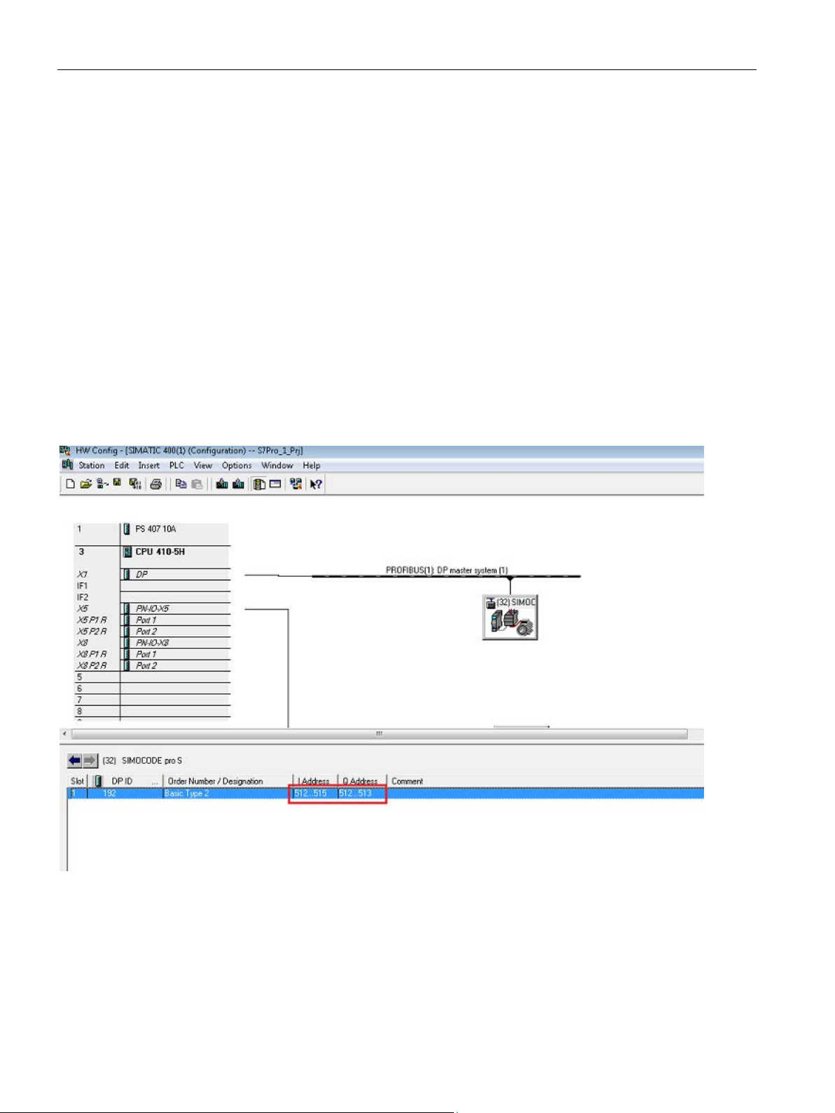
The two bytes of the process image inputs (PII) are transferred from the SIMOCODE device
based on the logical address configured for the module. This is a manual configuration that a
user has to configure for both the inputs and outputs.
● Drag and drop the desired SIMOCODE pro object (OM, PDM or GSD) out of the HW
Catalog into the "Station" window of HW Config and connect it to the desired fieldbus
(PROFIBUS or PROFINET).
● HW Config assigns the logical address to the object which will be used for setting up of
the CFC template.
SIMOCODE pro PCS 7 Library V9.0
14 Programming and Operating Manual, 06/2017, A5E40899442002A/RS-AA/001
Page 15
Introduction
Symbolic name in HW Config
1.5 Configuration Steps
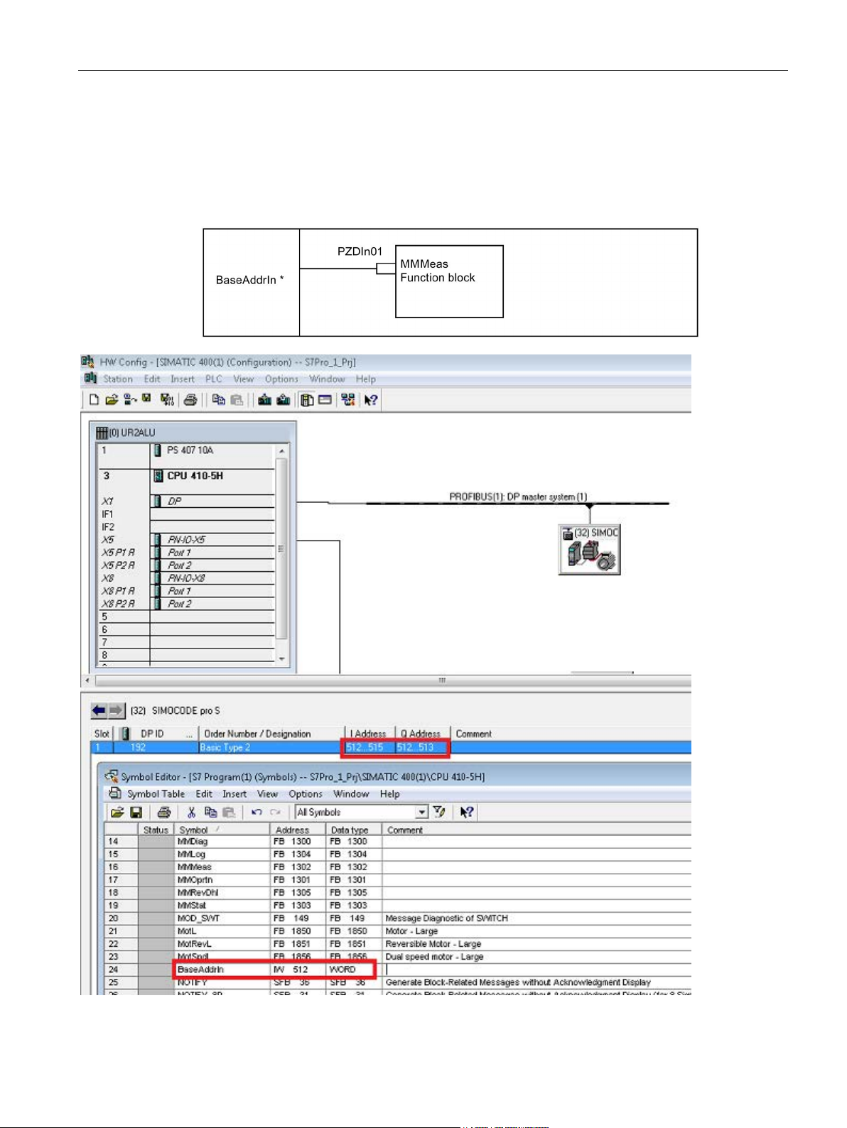
The PZDIn01 input parameter of the block is interconnected with the corresponding input of
the logical address of the device (
The logical word address can be assigned to a symbolic name (*).
LAddr).
Figure 1-1 Symbolic Name
SIMOCODE pro PCS 7 Library V9.0
Programming and Operating Manual, 06/2017, A5E40899442002A/RS-AA/001
15
Page 16

Introduction
1.5.2
Configuring in CFC
Procedure
Reference
1.5 Configuration Steps
The two bytes of the process image inputs (PII) are transferred from the SIMOCODE device
based on the logical address configured for the module. This is a manual configuration that a
user has to configure.
Configuring with HW Config:
1. Configure the SIMOCODE pro device at HW config.
2. Open CFC-Editor.
3. If not yet done, instantiate an appropriate template and open it.
4. Refer to the input address of the SIMOCODE pro device at HW Config and assign this
address to the textual interconnection "Input WORD address of SIMOCODE pro Module
(IW x)".
Compile the CFC chart using the "Generate Module Driver" function.
Additional information is available in the "Process Control System PCS 7 Compendium
Part A - Configuration Guidelines" Operating Manual on the Internet
(https://support.industry.siemens.com/cs/document/63187279
).
SIMOCODE pro PCS 7 Library V9.0
16 Programming and Operating Manual, 06/2017, A5E40899442002A/RS-AA/001
Page 17

Introduction
1.6
Driver generator
1.6.1
Driver generator
Purpose of the driver generator
Supported modules and configurations
1.6 Driver generator
The "Generate Module Drivers" function is available for signal processing in PCS 7. Once
the hardware has been configured in HW Config and the technological functions have been
configured in the CFC, this function automatically generates, interconnects, and
parameterizes the required module driver blocks, to the extent possible. These module driver
blocks are responsible for diagnosing and reporting errors during signal processing.
The Setup program installs XML files for connecting SIMOCODE pro C / S / V with the driver
generator.
A template is inserted for each SIMOCODE pro device. The connection to the hardware is
established using symbolic addressing.
The "Generate Module Driver" option inserts the additionally required blocks, and then
connects and assigns the corresponding parameters.
The driver concept for SIMOCODE pro C / S / V modules takes into account the operation of
various SIMOCODE control functions:
● As a DP slave direct on the DP master system (connection via GSD, PDM object or S7
module via OM SIMOCODE pro)
● As a DP slave behind a Y-Link (connection via GSD or PDM object)
● As a PROFINET IO Device direct on the PN-IO Controller (with or without system
redundancy, connection via GSD or S7 module via OM SIMOCODE pro PN or via EDD).
● As a shared PN IO Device in conjunction with a PROFIsafe configuration with DM-F
PROFIsafe fail-safe digital module on two different IO Controllers (connection via GSD or
S7 module via OM SIMOCODE pro PN or via EDD) for a GSD-file-based configuration.
● As a DP slave behind IE-PB-Link (connection via GSD, PDM object or S7 module via OM
SIMOCODE pro).
SIMOCODE pro PCS 7 Library V9.0
Programming and Operating Manual, 06/2017, A5E40899442002A/RS-AA/001
17
Page 18

Introduction
Reference
Note
The SIMOCODE
Premium configuring software. To install, select the appropriate "SIMOCODE pro Integration
in STEP 7" option when executing the Setup program for SIMOCODE pro.
See also
1.6 Driver generator
1. You will find the GSD files for SIMOCODE pro C / S / V PROFIBUS
(https://support.industry.siemens.com
(https://support.industry.siemens.com/cs/document/38702563) on the Internet
(https://support.industry.siemens.com).
2. Enter one of the following search terms in the "Product Name / Article Number" field
under "Search Product Support Documents":
– SIMOCODE pro C GSD
– SIMOCODE pro S GSD
– SIMOCODE pro V GSD
– SIMOCODE pro V PN GSD
3. Under Downloads click the relevant entry,
e.g., "PROFINET GSD files : Switching Devices" or "PROFIBUS GSD files :
SWITCHGEARS".
4. This displays another Internet page where you can download the GSD files.
) and PROFINET
pro object manager (OM) is a component part of the SIMOCODE ES 2007
PROFIBUS (https://support.industry.siemens.com/cs/document/113630)
SIMOCODE pro PCS 7 Library V9.0
18 Programming and Operating Manual, 06/2017, A5E40899442002A/RS-AA/001
Page 19

Introduction
1.6.2
Requirements for generating the module drivers
Article number
SIMOCODE pro
Compatible modules
3UF7000-1A*00-0
SIMOCODE pro C (PROFIBUS DP)
yes
basic unit 1, 2 and 3 (PROFINET)
basic unit 1 and 2
1.6 Driver generator
The following SIMOCODE pro modules are permitted for the PCS 7 Library V9.0:
3UF7010-1A*00-0 SIMOCODE pro V
basic unit 1 and 2 (PROFIBUS DP)
3UF7011-1A*00-0 SIMOCODE pro V PN
3UF7020-1A*01-0 SIMOCODE pro S
yes
yes
yes
The desired template is inserted into the CFC from the SIMOCODE library.
Assign the input address of the SIMOCODE pro device to the textual interconnection "Input
WORD address of SIMOCODE pro Module (IW x)" for linking the parameters PZDIn01
(SIMOCODE blocks) / PZDIn1(FbSwtMMS) with the logical address of the starter.
Reproduce the above steps for the other SIMOCODE pro function blocks at the CFC chart, if
you are planning to use any or all of the additional blocks (MMStat, MMMeas and/or MMLog)
shipped with this library.
PZDOut1(FbSwtMMS) also has to be connected to Output address (or), Input address and
Output address should be maintained same while configuring.
The CFC chart is compiled using the "Generate module driver" function.
SIMOCODE pro PCS 7 Library V9.0
Programming and Operating Manual, 06/2017, A5E40899442002A/RS-AA/001
19
Page 20

Introduction
1.6.3
Driver blocks
Generating the driver blocks
1.6.4
Object lists and action lists
Description
1.6 Driver generator
Module driver generation for the signal blocks will insert driver blocks depending on the HW
Configuration.
The action includes the following steps:
● Determining and assigning the diagnostics address of the SIMOCODE pro device.
● Assigning the primary subnet address and module rack number for the SIMOCODE pro
device.
● Instantiating the OB_DIAG1 / OB_DIAG1_PN driver block for the SIMOCODE pro device.
● Instantiating the MMDiag driver block for reading the diagnostics information of the
SIMOCODE pro device.
● Setting the address of the device at the OB_DIAG1 / OB_DIAG1_PN, MMDiag and
MOD_SWT blocks.
● Creating interconnections between the OB_DIAG1 / OB_DIAG1_PN, MMDiag and
MOD_SWT blocks.
● Assigning the diagnostic address in the
● Making interconnections between the MMOprtn, MMMeas, MMStat and MMLog blocks
and the MMDiag and MOD_SWT blocks.
DAddr parameter.
Hardware modules, among other things, are configured in HW Config.
The object lists and the action lists are used to generate the module drivers for these
hardware modules.
The object list contains a unique object identification number for each of these hardware
modules. Each object list is assigned to a particular hardware configuration.
The action list contains a list of actions. These actions must be executed for the object
identification numbers that appear in the object list. Examples of such actions include:
● Assigning the device address
● Interconnecting the input and output parameters of the driver block
The "Generate Module Driver" function generates the module drivers when the CFC is
compiled.
SIMOCODE pro PCS 7 Library V9.0
20 Programming and Operating Manual, 06/2017, A5E40899442002A/RS-AA/001
Page 21
Introduction
1.7
Example configurations
1.7.1
SIMOCODE pro PROFIBUS and PROFINET Configuration
SIMOCODE pro PROFIBUS and PROFINET configurations
Note
SIMOCODE pro is used in DP mode DPV1 with a
1.7.2
SIMOCODE pro PROFIBUS configuration
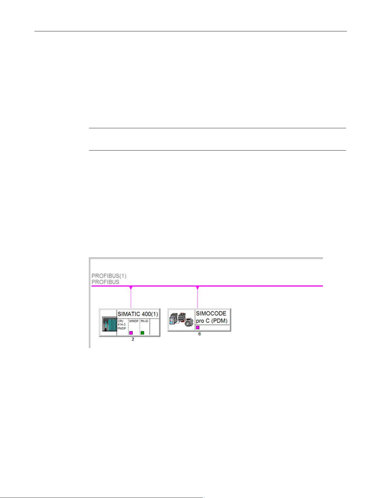
SIMOCODE pro C on DP master system
1.7 Example configurations
ctivated diagnostics and process interrupt.
The SIMOCODE pro PROFIBUS and PROFINET devices along with their associated
components are inserted and configured in HW Config.
The following graphics show example configurations of SIMOCODE pro at HW Config in the
Netpro View.
Figure 1-2 SIMOCODE pro C on DP master system
SIMOCODE pro PCS 7 Library V9.0
Programming and Operating Manual, 06/2017, A5E40899442002A/RS-AA/001
21
Page 22
Introduction
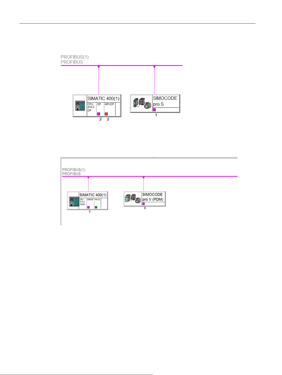
SIMOCODE pro S on DP master system
SIMOCODE pro V on DP master system
1.7 Example configurations
Figure 1-3 SIMOCODE pro S on DP master system
Figure 1-4 SIMOCODE pro V on DP master system
SIMOCODE pro PCS 7 Library V9.0
22 Programming and Operating Manual, 06/2017, A5E40899442002A/RS-AA/001
Page 23
Introduction
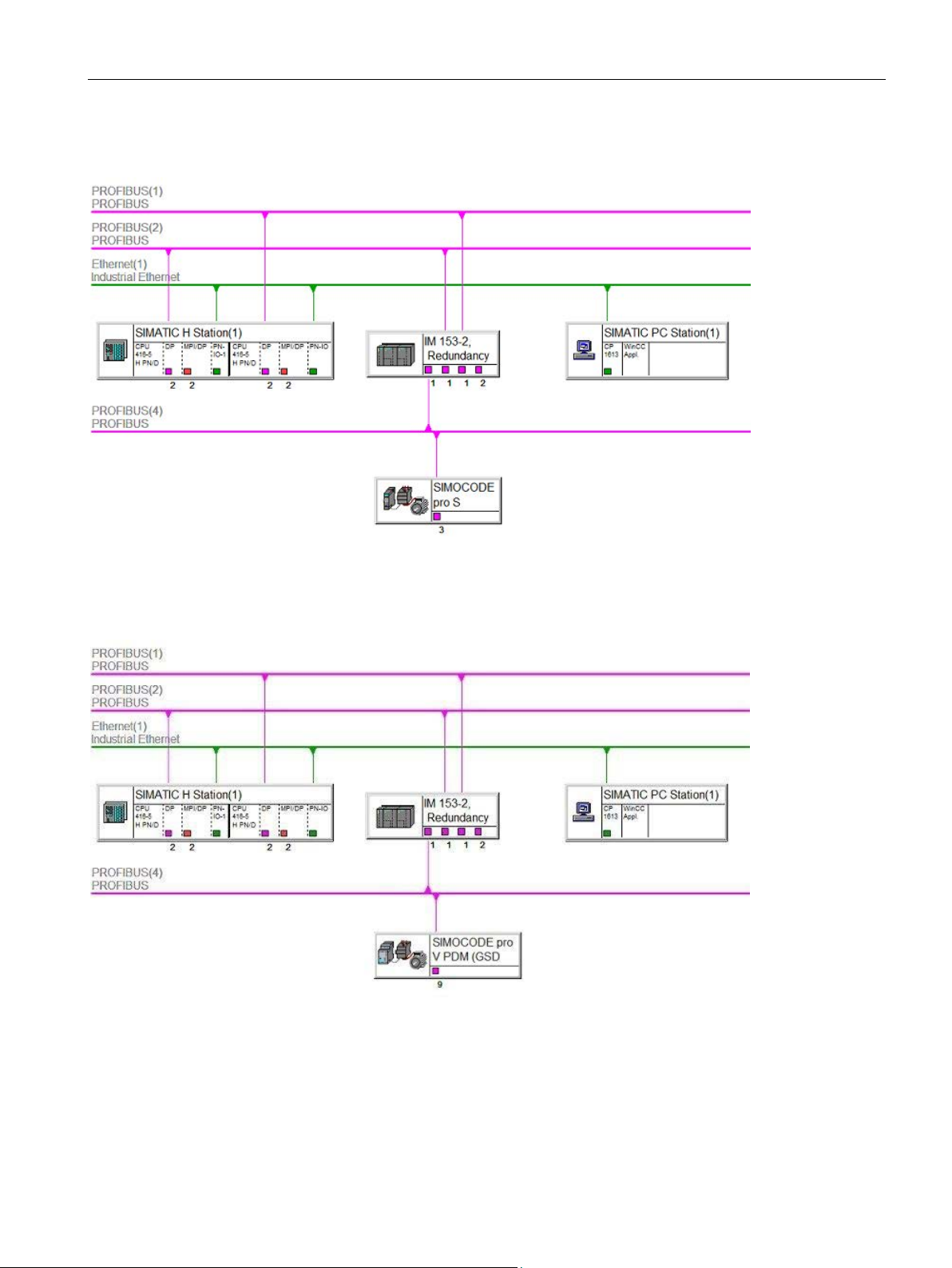
SIMOCODE pro S on PROFIBUS DP behind a Y-link
SIMOCODE pro V on PROFIBUS DP behind a Y-link
1.7 Example configurations
Figure 1-5 SIMOCODE pro S on PROFIBUS behind a Y-link
Figure 1-6 SIMOCODE pro V on PROFIBUS behind a Y-link
SIMOCODE pro PCS 7 Library V9.0
Programming and Operating Manual, 06/2017, A5E40899442002A/RS-AA/001
23
Page 24
Introduction
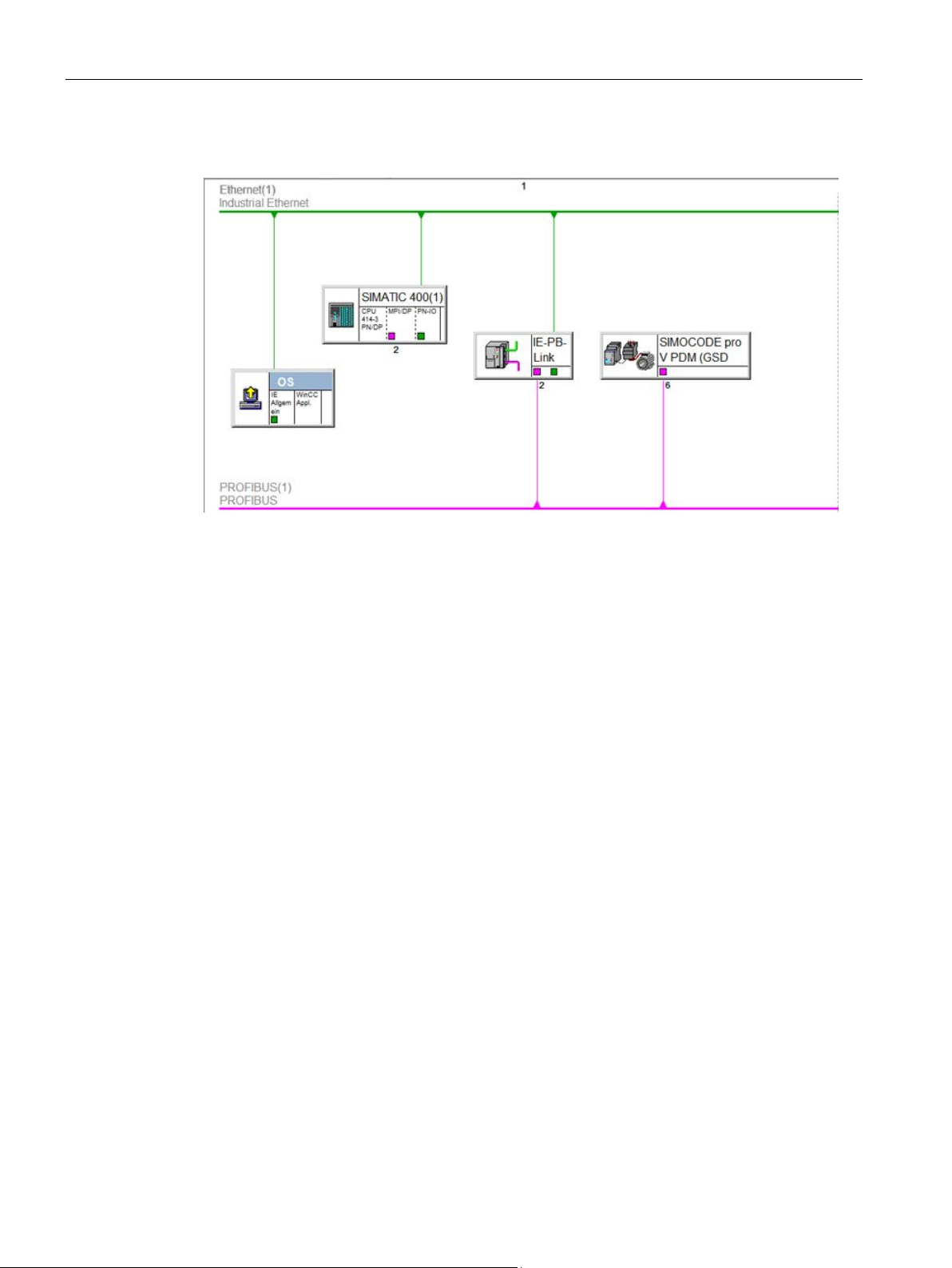
SIMOCODE pro C / S / V behind IE-PB-Link (OM / GSD)
1.7.3
SIMOCODE pro PROFINET configuration
SIMOCODE pro V PN Configurations
Standalone Configurations (With Internal CPU/External PROFINET card interface)
In CPU
1.7 Example configurations
Figure 1-7 SIMOCODE pro C / S / V behind IE-PB-Link (OM / GSD)
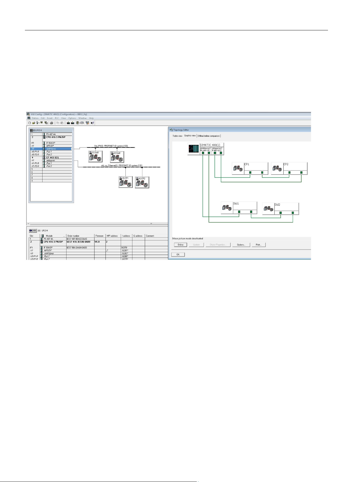
PROFINET port monitoring settings are made mandatory. When multiple devices are
connected to the CPU/CP card interface, used and unused PROFINET port settings are
required to distinguish between actual Rack failure and Device Failure.
When multiple devices are connected to the PROFINET interface, then the following settings
needs to be done.
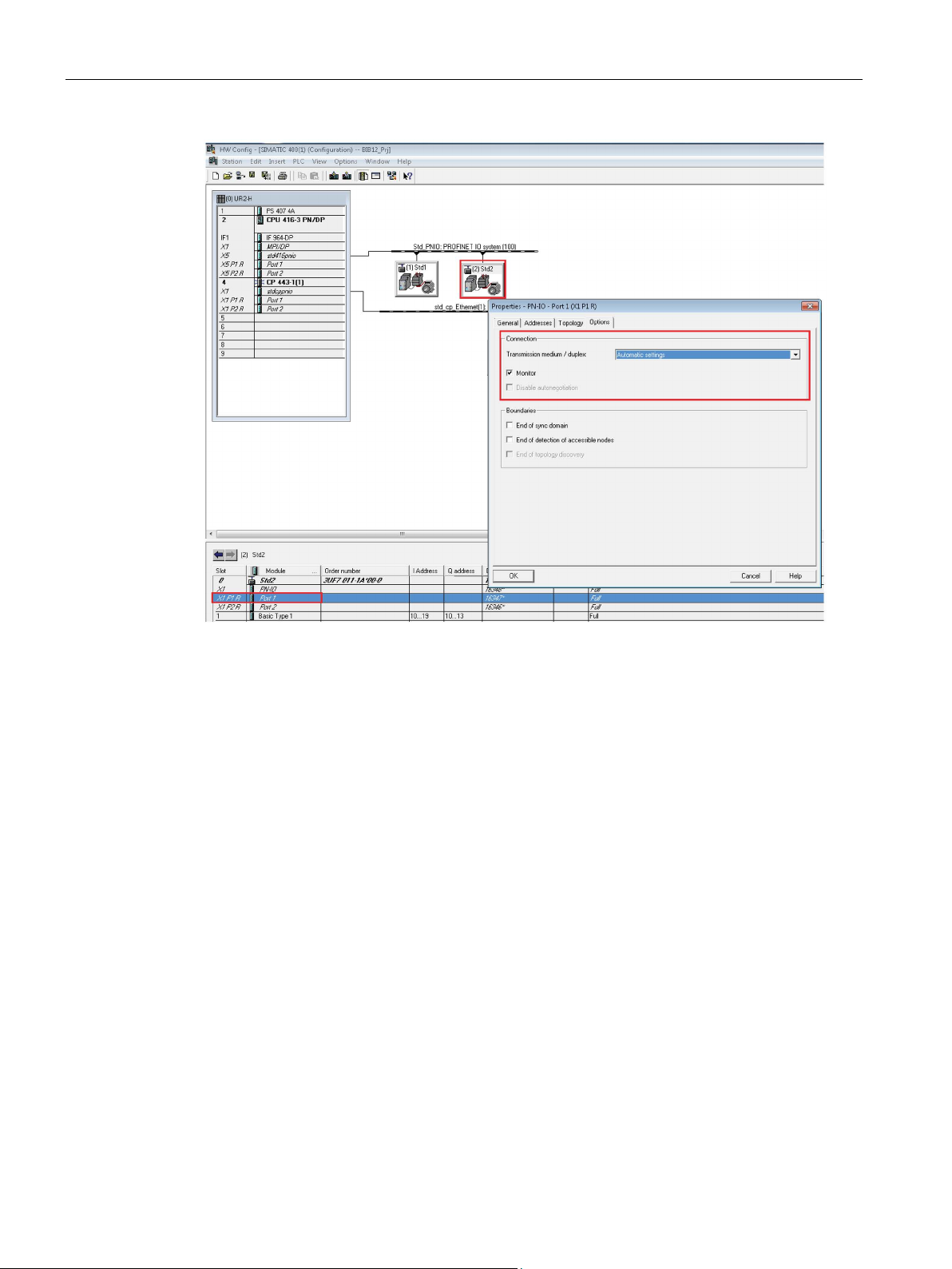
1. In Port 1 of the PROFINET interface, "Transmission medium" should be automatic and
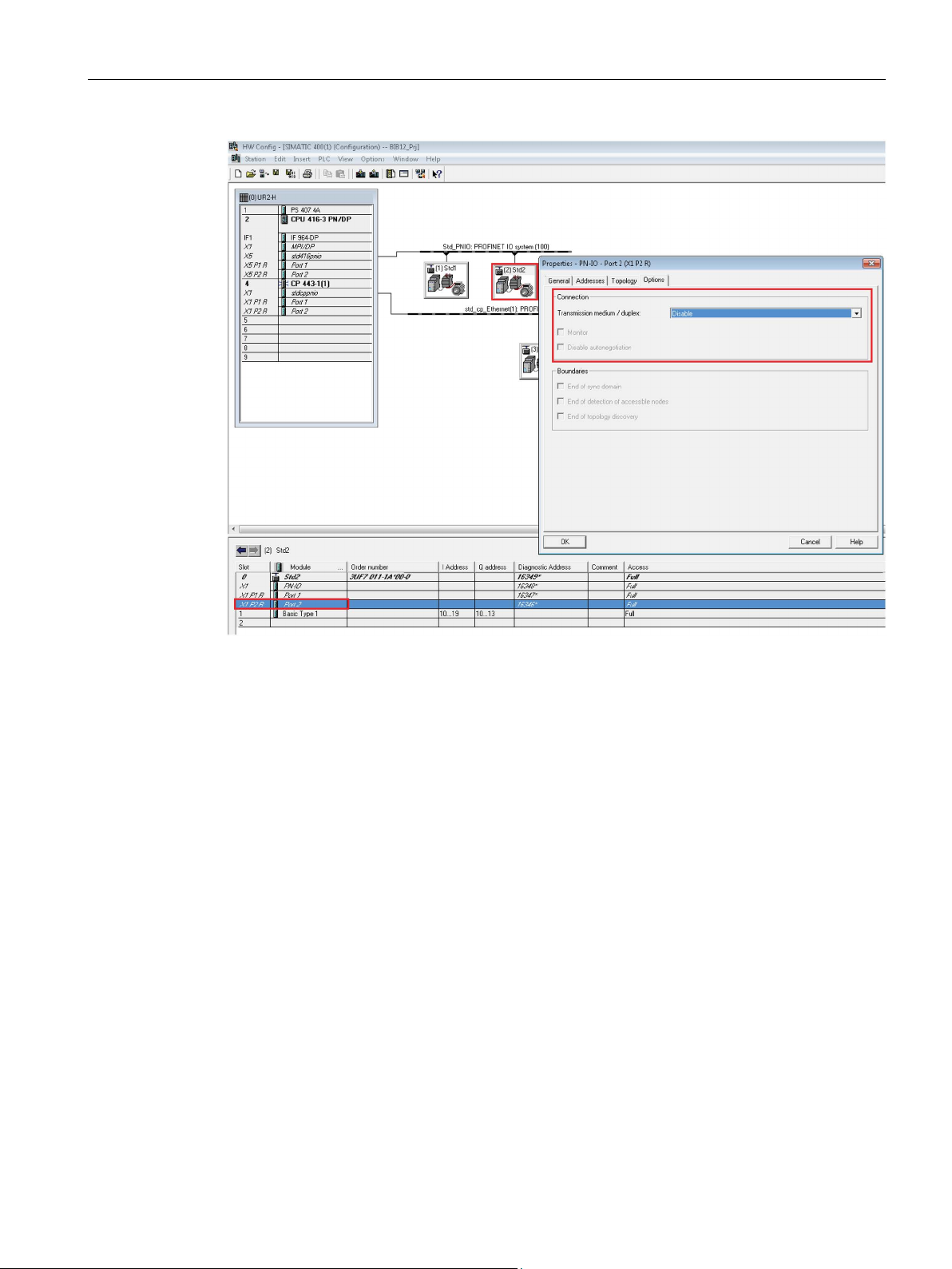
2. In Port 2 of the PROFINET card, "Transmission medium" and the "Monitor" checkbox
the "Monitor" checkbox needs to activated as shown in figure.
needs to be disabled as shown in figure.
SIMOCODE pro PCS 7 Library V9.0
24 Programming and Operating Manual, 06/2017, A5E40899442002A/RS-AA/001
Page 25

Introduction
In Device
Note
By default when you add a device “Transmission medium” is set to Automatic and Monitor”
checkbo
1.7 Example configurations
Similarly "Transmission medium" should be automatic and "Monitor" checkbox needs to be
activated for Port1 and Port 2 of all the SIMOCODE pro V PN devices (see figure) except for
the last device in the network loop where Port 2 should be disabled as shown in figure.
These settings are applicable in both internal PROFINET interface of the PLC and external
PROFINET interface of CP Card.
Figure 1-8 Standalone configurations
x is disabled.
SIMOCODE pro PCS 7 Library V9.0
Programming and Operating Manual, 06/2017, A5E40899442002A/RS-AA/001
25
Page 26
Introduction
MRP Redundancy (With Internal CPU/External PROFINET card interface)
System Redundancy (S2) configuration with Redundant PLC
At the Master CPU:
At the Standby CPU:
1.7 Example configurations
When multiple devices are connected in MRP configuration, then the topology below with the
required port settings needs to be done as given below
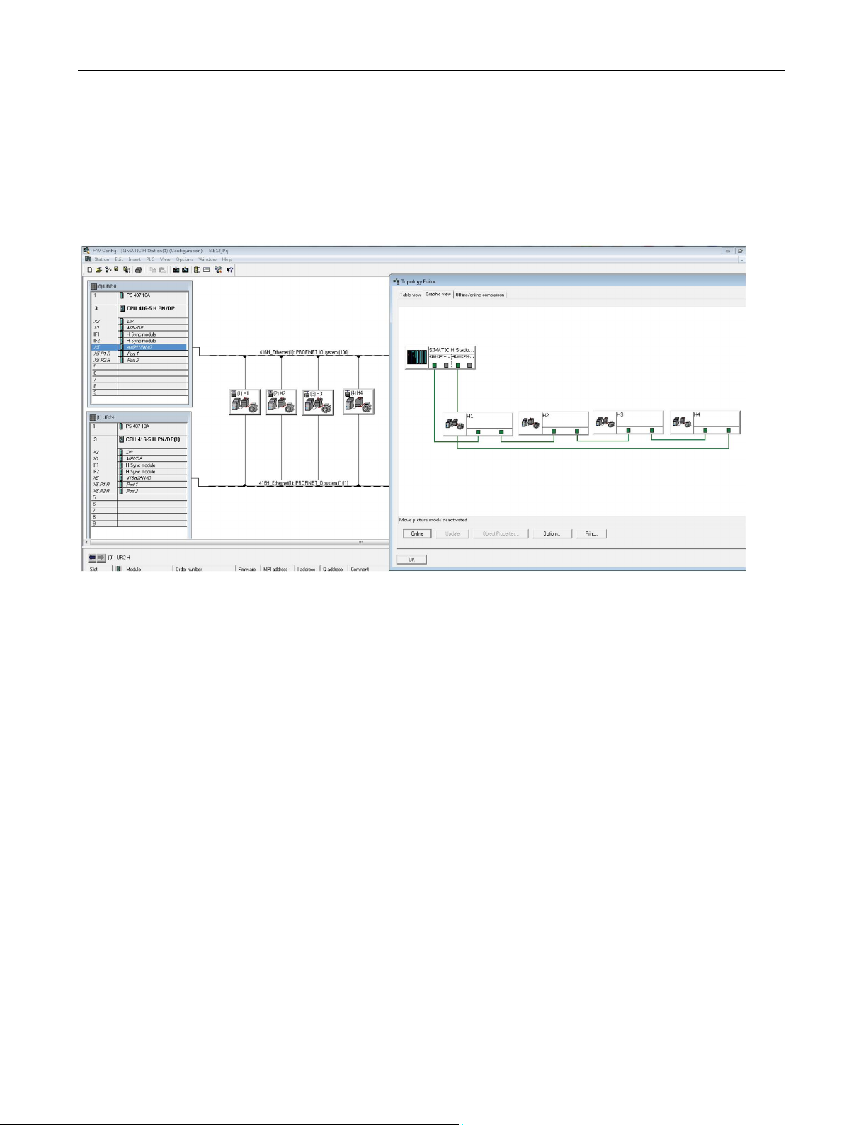
● In Port 1 and Port 2 of the CPU PROFINET interface and the Simocode pro V PN
devices, “Transmission medium” should be automatic and the “Monitor” checkbox needs
to be activated.
Figure 1-9 MRP configuration
In a redundant CPU configuration,”S2 Redundancy” can be achieved with SIMOCODE pro V
PN devices by connecting with the internal PROFINET interface of the CPU as shown with
the required port settings needs to be done as given below.
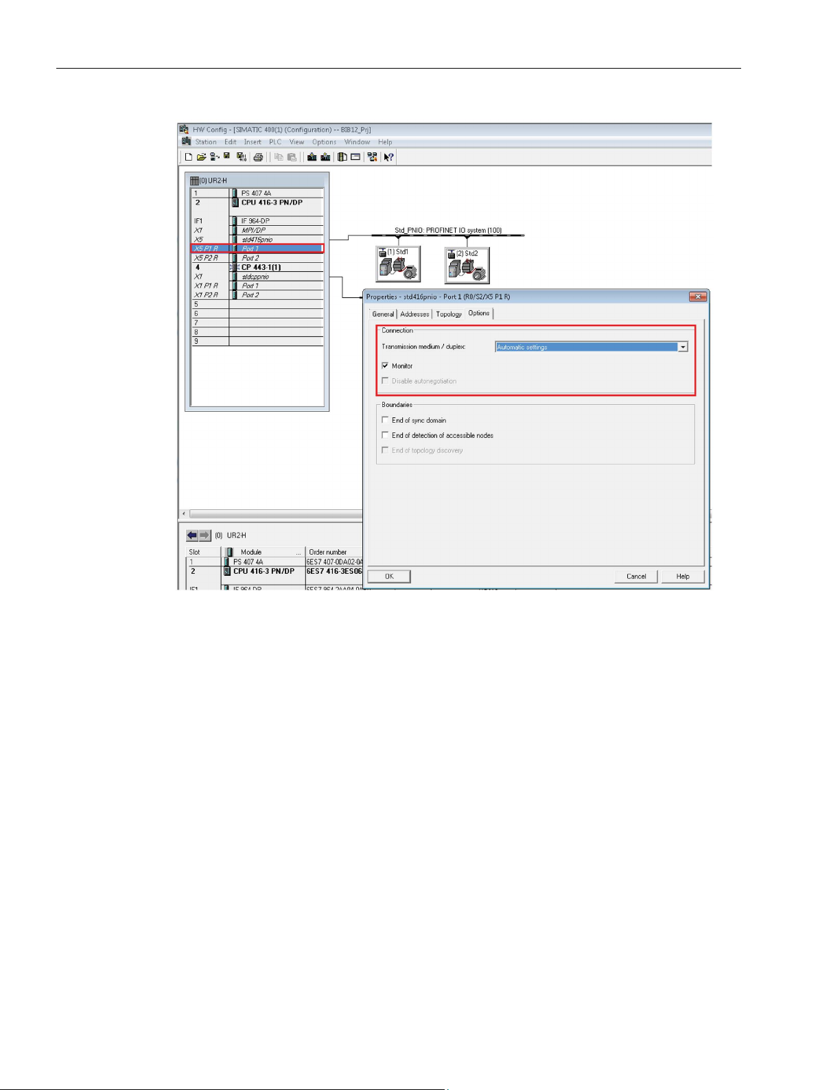
1. In Port 1 of the PROFINET interface, “Transmission medium” should be automatic and
the “Monitor” checkbox needs to activated as shown in figure.
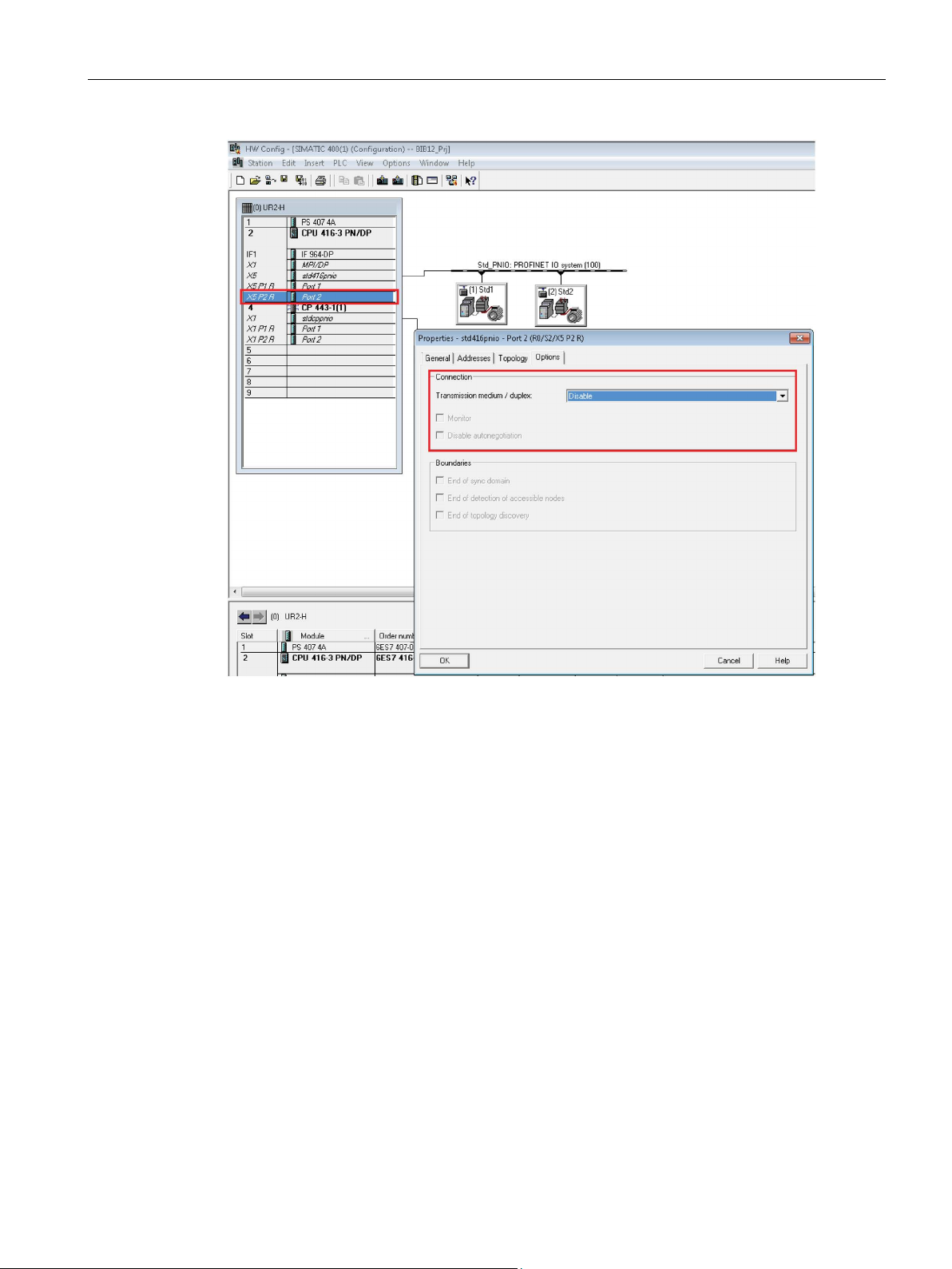
2. In Port 2 of the PROFINET card, “Transmission medium” and the “Monitor” checkbox
needs to be disabled as shown in figure.
1. In Port 1 of the PROFINET interface, "Transmission medium" should be automatic and
the "Monitor" checkbox needs to activated as shown in figure.
2. In Port 2 of the PROFINET card, "Transmission medium" and the "Monitor" checkbox
needs to be disabled as shown in figure.
SIMOCODE pro PCS 7 Library V9.0
26 Programming and Operating Manual, 06/2017, A5E40899442002A/RS-AA/001
Page 27
Introduction
At SIMOCODE pro V PN Device:
1.7 Example configurations
Similarly “Transmission medium” should be automatic and “Monitor” checkbox needs to
activated for Port1 and Port 2 of all the SIMOCODE pro V PN devices connected in
redundant configuration.
Figure 1-10 System Redundancy (S2) configuration
SIMOCODE pro PCS 7 Library V9.0
Programming and Operating Manual, 06/2017, A5E40899442002A/RS-AA/001
27
Page 28
Introduction
1.7 Example configurations
Figure 1-11 Enabling Port1 of the CPU Interface
SIMOCODE pro PCS 7 Library V9.0
28 Programming and Operating Manual, 06/2017, A5E40899442002A/RS-AA/001
Page 29
Introduction
1.7 Example configurations
Figure 1-12 Disabling Port2 of the CPU Interface
SIMOCODE pro PCS 7 Library V9.0
Programming and Operating Manual, 06/2017, A5E40899442002A/RS-AA/001
29
Page 30
Introduction
1.7 Example configurations
Figure 1-13 Enabling Port1 of the Device Interface
SIMOCODE pro PCS 7 Library V9.0
30 Programming and Operating Manual, 06/2017, A5E40899442002A/RS-AA/001
Page 31
Introduction
1.7 Example configurations
Figure 1-14 Disabling Port2 of the Device Interface
SIMOCODE pro PCS 7 Library V9.0
Programming and Operating Manual, 06/2017, A5E40899442002A/RS-AA/001
31
Page 32

Introduction
1.8
Parameterization softwares
1.8.1
Parameterization Softwares
Parameterization Softwares
1.8.2
Configuring in SIMOCODE ES
Purpose of the SIMOCODE ES software
Note
Transmission of modified device parameters is possible under the following conditions:
•
not
•
•
Note
Some device parameters can be modified independently of the conditions named above.
You can recognize these parameters by the blue motor symbol in front of the parameter.
1.8 Parameterization softwares
For parametrizing the device following softwares are availible:
- SIMOCODE ES (with OM intergration)
- SIMATIC PDM (with EDD)
- GSD
SIMOCODE ES is used to configure SIMOCODE pro devices.
The device is
No ON control command is active.
No motor current is flowing.
in the SIMOCODE pro "remote" mode.
SIMOCODE pro PCS 7 Library V9.0
32 Programming and Operating Manual, 06/2017, A5E40899442002A/RS-AA/001
Page 33

Introduction
Parameter settings
General settings (valid for all control functions)
Device parameters → Bus parameters
Diagnosis triggered by device fault
Active
—
Diagnosis triggered by process warnings
Active
—
sages
SIMATIC PDM
Standard functions → Test/reset
Test 1
Cyclic receive bit 0.3
—
Reset 1
Cyclic receive bit 0.6
—
Emergency start
Cyclic receive bit 0.4
—
1.8 Parameterization softwares
SIMOCODE pro requires that some parameters have specific settings to ensure correct
operation of the signal blocks:
● Parameters that define the assignment of the cyclic I/O interface. These parameters are
italics
shown in
● Parameters that are already preset in the templates for application selection in
SIMOCODE ES for the control function (*).
in the following overview.
Diagnosis triggered by process faults
* Diagnosis triggered by process mes-
Startup parameter block
The settings are a suggestion. They depend on the actual wiring of the SIMOCODE pro
inputs and outputs.
Settings for other parameters are required, for example, for motor protection. These are not
described here.
Active
—
Not active —
Active
Configuration with SIMOCODE ES or
SIMOCODE pro PCS 7 Library V9.0
Programming and Operating Manual, 06/2017, A5E40899442002A/RS-AA/001
33
Page 34

Introduction
1.8.2.1
Parameter settings
Control function
Template
APL block
Parameters in SIMOCODE ES
Nonmaintained
command
Saving
changeover
command
Feedback
time
Execution
time
Interlocking time
Changeover
pause
Overload relay
OvlRly
MMOprtn
– – – – –
–
①
①
①
①
ing starter
① ②
①
③
ing starter
starter
①
③
reversing starter
①
① ②
① ②
① ②
① ②
① ②
①
starter
① ②
①
②
③
– not applicable
1.8 Parameterization softwares
The following list shows the settings for the parameters in SIMOCODE ES.
Table 1- 3 Parameter settings in SIMOCODE ES
Direct starter Direct MotL Default –
Reversing starter Reverse MotRevL Default Default
Circuit breaker MCCB MotL Default –
Star-delta starter StarDel MotL Default –
Star-delta revers-
Dahlander Dahland MotSpdL Default Default
Dahlander revers-
RevStarDel MotRevL Default Default
DevDahl MMRevDhl Default Default
– –
–
– –
– –
–
–
① ② ③
Pole-changing
Pole-changing
Solenoid valve SolValve VlvL Default – –
Positioner 1 Positner VlvMotL Default –
Positioner 2 Positner VlvMotL Default Default
Positioner 3 Positner VlvMotL Default –
Positioner 4 Positner VlvMotL Default –
Positioner 5 Positner VlvMotL Default –
Soft starter SoftStr MotL Default –
Soft reversing
< Dynamic monitoring time, MonTiDynamic ≥ MonTiStatic, MonTiDyStop
< Pause time, IdleTime
< Change-over time, SwOverTi
PoleChng MotSpdL Default Default
RevPoleCh MMRevDhl Default Default
RevSoftStr MotRevL Default Default
–
① ② ③
– –
– –
–
–
–
–
–
–
SIMOCODE pro PCS 7 Library V9.0
34 Programming and Operating Manual, 06/2017, A5E40899442002A/RS-AA/001
Page 35

Introduction
Note
For Star
device should be added along with Feedback/Execution time for Star
parameterized in ( < Dynamic monitoring time, MonTiDynamic = MonTiStatic).
1.8.3
Configuration with SIMATIC PDM
Note
Transmission of modified device parameters is possible under the following conditions:
•
not
•
•
1.8.4
Device type selection in HW Config
Note
SIMOCODE pro V PN
PCS 7 V8.1 and above support integration of SIMOCODE
PDM.
1.8 Parameterization softwares
-Delta starter and Star-Delta reverse starter, Change over pause time configured in
-Delta and
You can use the SIMATIC PDM software to configure the SIMOCODE pro C / S / V devices.
The devices are accessed via the PROFIBUS and PROFINET interface.
You can find information on configuration using the SIMATIC PDM software in the
documentation for SIMATIC PDM and SIMOCODE pro EDD.
The device is
in the SIMOCODE pro "remote" mode.
No ON control command is active.
No motor current is flowing.
You can select the device type in the HW Config as follows:
1. Start the SIMATIC Manager.
2. Open the "Settings" menu via "Options → SIMATIC PDM → Settings".
The dialog box opens.
3. Enable "Select type when device is inserted in HW Config".
4. Confirm by clicking OK and close the dialog box.
5. Close SIMATIC Manager and integrate EDD using the SIMATIC PDM "Device Integration
Manager".
pro V PN devices using SIMATIC
SIMOCODE pro PCS 7 Library V9.0
Programming and Operating Manual, 06/2017, A5E40899442002A/RS-AA/001
35
Page 36

Introduction
1.9
Configuring of the fail-safe, digital PROFIsafe module
Address assignment
Byte in FCPU
Bit 7
Bit 6
Bit 5
Bit 4
Bit 3
Bit 2
Bit 1
Bit 0
x+0 — — — — — — — Output
Note
You are only allowed to access the address reserved for user data (output byte
Other address ranges assigned by DM
safety
according to PROFIsafe.
Additional information
1.9 Configuring of the fail-safe, digital PROFIsafe module
From product version E06 onwards, SIMOCODE pro V supports the DM-F PROFIsafe failsafe module, with which safety-related tripping of the motor is possible from an F-CPU via
PROFIBUS / PROFIsafe.
From the perspective of the fail-safe section of the controller that transfers fail-safe signals
via PROFIBUS / PROFIsafe, the DM-F PROFIsafe module represents a digital output with
which the two relay enabling circuits of the DM-F PROFIsafe module can be switched on
simultaneously or tripped in a fail-safe manner.
To enable fail-safe tripping via the DM-F PROFIsafe by the F-CPU, the PROFIsafe module
must be configured in addition to the module for basic type 1 or 2 when integrating via GSD
or PDM. When integrating via OM SIMOCODE pro, configuring must be carried out with
PROFIsafe.
Of the DM-F PROFIsafe module's assigned addresses, user data is assigned to the following
output address in the F-CPU:
Detailed information on accessing the F I/O can be found in the S7 F / FH Systems,
Configuring and Programming (https://support.industry.siemens.com/cs/document/2201072
manual.
x, bit 0).
-F PROFIsafe, are, among other things, reserved for
-related communication between the DM-F PROFIsafe module and the F-CPU
)
SIMOCODE pro PCS 7 Library V9.0
36 Programming and Operating Manual, 06/2017, A5E40899442002A/RS-AA/001
Page 37

Introduction
Assignment of the PROFIsafe address
Additional information
1.10
Update an existing PCS 7 project
Performing a project update
1.11
Further documentation
Overview
1.10 Update an existing PCS 7 project
Each DM-F PROFIsafe fail-safe digital module has its own PROFIsafe address. You must
set the PROFIsafe address on the module prior to commissioning.
The PROFIsafe addresses (
configure the DM-F PROFIsafe module in STEP 7.
You can find the PROFIsafe address that must be set on the DM-F PROFIsafe module in the
HW Config under the object properties for the PROFIsafe module; it is shown in decimal and
hexadecimal notation in the
and set it via the DIP address switch on the DM-F PROFIsafe module.
Enter an icon for the fail-safe output in HW Config. In conjunction with F systems, this icon is
then connected in CFC with the fail-safe channel driver (output VALUE). When integrating
SIMOCODE pro V with GSD file via the Object Manager (OM), the F_CH_BO block is used
as the channel driver.
Refer to the system manual "SIMOCODE pro Safety - fail-safe digital modules
(https://support.industry.siemens.com/cs/document/50564852
using the fail-safe digital modules.
F_Source_Add, F_Dest_Add) are automatically assigned when you
F_Dest_Add parameter. Convert this address to binary notation
)" for more information on
Refer "ReadMe" provided with the library.
More information
● Online help for PCS 7 Advanced Process Library
● Online help for SIMATIC PCS 7 Process Control System
● Function manuals for SIMATIC PCS 7 Process Control System on the Internet
(https://support.industry.siemens.com/cs/ww/en/view/109482346
● System Manual SIMOCODE pro PROFINET on the Internet
(https://support.industry.siemens.com/cs/document/61896631
● Getting Started on the Internet
(https://support.industry.siemens.com/cs/ww/en/view/109482390
)
)
).
SIMOCODE pro PCS 7 Library V9.0
Programming and Operating Manual, 06/2017, A5E40899442002A/RS-AA/001
37
Page 38

2
2.1
Overview of the templates, control functions and blocks
Templates for the control functions
No.
Control function
Template
APL blocks
SIMOCODE
blocks
1
Overload relay
OvlRly (Page 42)
FbSwtMMS
FbSwtMMS
FbSwtMMS
FbSwtMMS
FbSwtMMS
FbSwtMMS
FbSwtMMS
MMLog
The templates from the SIMOCODE pro PCS 7 Library V9.0 are templates that you can
adopt unchanged to implement control functions in your project. The templates thus simplify
the engineering for configuring the blocks and they support their problem-free functioning.
You can also modify the templates or create completely new ones. The interconnections that
must then be created manually can be found in the available templates.
The table below assigns the possible control functions to the associated template:
Table 2- 1 Templates for the control functions
2 Direct starter Direct (Page 43) MotL1
Event16Ts
3 Reversing starter Reverse (Page 44) MotRevL1
Event16Ts
4 Circuit breaker MCCB (Page 45) MotL1
Event16Ts
5 Star-delta starter StarDel (Page 46) MotL1
Event16Ts
6 Star-delta reversing starter RevStarDel (Page 47) MotRevL1
Event16Ts
7 Dahlander Dahland (Page 48) MotSpdL1
Event16Ts
8 Dahlander reversing starter RevDahl (Page 49) Event16Ts
FbSwtMMS
9 Pole-changing starter PoleChng (Page 50) MotSpdL1
Event16Ts
FbSwtMMS
MMOprtn1
MMMeas
MMStat
MMLog
MMRevDhl1
MMOprtn1
MMMeas
MMStat
MMLog
MMOprtn1
MMMeas
MMStat
SIMOCODE pro PCS 7 Library V9.0
38 Programming and Operating Manual, 06/2017, A5E40899442002A/RS-AA/001
Page 39

Templates
No.
Control function
Template
APL blocks
SIMOCODE
blocks
MMLog
FbSwtMMS
FbSwtMMS
FbSwtMMS
FbSwtMMS
1
Block icon available
Reference
See also
2.2
Using templates
2.2 Using templates
10 Pole-changing reversing
starter
11 Valve SolValve (Page 52) VlvL1
12 Positioners 1–5 Positner (Page 53) VlvMotL1
13 Soft starter SoftStr (Page 54) MotL1
14 Soft reversing starter RevSoftStr (Page 55) MotRevL1
RevPoleCh (Page 51) Event16Ts
FbSwtMMS
Event16Ts
Event16Ts
Event16Ts
Event16Ts
MMRevDhl1
MMOprtn1
MMMeas
MMStat
MMOprtn1
MMMeas
MMStat
MMLog
For more information about the APL blocks, refer to the Function Manual "Process Control
System PCS7, PCS7 Advanced Process Library V9.0" on the Internet (Page 42).
Diagnostics block MMDiag (Page 94)
MMOprtn block (Page 100)
Block for MMMeas measured value function (Page 154)
Block for statistical function MMStat (Page 172)
Block for timestamping MMLog (Page 183)
MMRevDhl motor block (Page 197)
PCS7 Process Control System, PCS7 Advanced Process Library V9.0
(https://support.industry.siemens.com/cs/ww/en/view/109482346
)
The templates for the control functions are located in the SIMOCODE pro Library under:
SMCPro PCS7 LibV90> Blocks+Templates\Templates >
Select a template, e.g.
chart. Alternatively, you can also copy the template direct to the chart container or to the
required location in the technological hierarchy view.
Reverse
for a reversing starter, and drag and drop it to the CFC
SIMOCODE pro PCS 7 Library V9.0
Programming and Operating Manual, 06/2017, A5E40899442002A/RS-AA/001
39
Page 40

Templates
Manual interconnections
Automatic interconnections
CFC Sheet 1
CFC Sheet 2
2.2 Using templates
To edit the template, right-click on the template and select "Open" from the shortcut menu.
The template is opened as a CFC chart.
In the CFC chart, connect "Input Word Address of SIMOCODE base Module" in the left-hand
sheet bar with the logical address of the basic unit.
There are two ways of doing this:
● Via the already created symbolic name
● Via direct input of the calculated address
If additional blocks/functionalities available at the template in sheet 2 of the CFC are not
required, they can be deleted as well.
Refer to the section "Remove unused blocks" below for further information.
If the option "Generate Block Driver“ is activated in the "Compile Program" dialog,
interconnections that are not yet available but that are necessary will be automatically
executed.
Table 2- 2 Automatic interconnections
Inputs
Outputs
• Diagnostic Address of SIMOCODE pro Module
• Logical Address of SIMOCODE pro Module
• ModFAct from MMDiag
• Slv_Typ from MMDiag
• RdEn from MMDiag
• RackFAct from MMDiag
• OMODE_00 of MOD_SWT
• Output word of the basic module
–
In addition to the interconnections, the driver generator automatically generates the following
charts and connects them with the template:
● SUBNET/SUBNET_P
● OB_DIAG1 / OB_DIAG1_PN
● MMDiag
● MOD_SWT
The textual interconnections supplied in the template can be deleted individually and entirely.
The driver generator replaces the textual interconnections automatically.
SIMOCODE pro PCS 7 Library V9.0
40 Programming and Operating Manual, 06/2017, A5E40899442002A/RS-AA/001
You can delete the textual interconnections using the menu command Options → Delete
Textual Interconnections.
Page 41
Templates
Remove unused blocks
Note
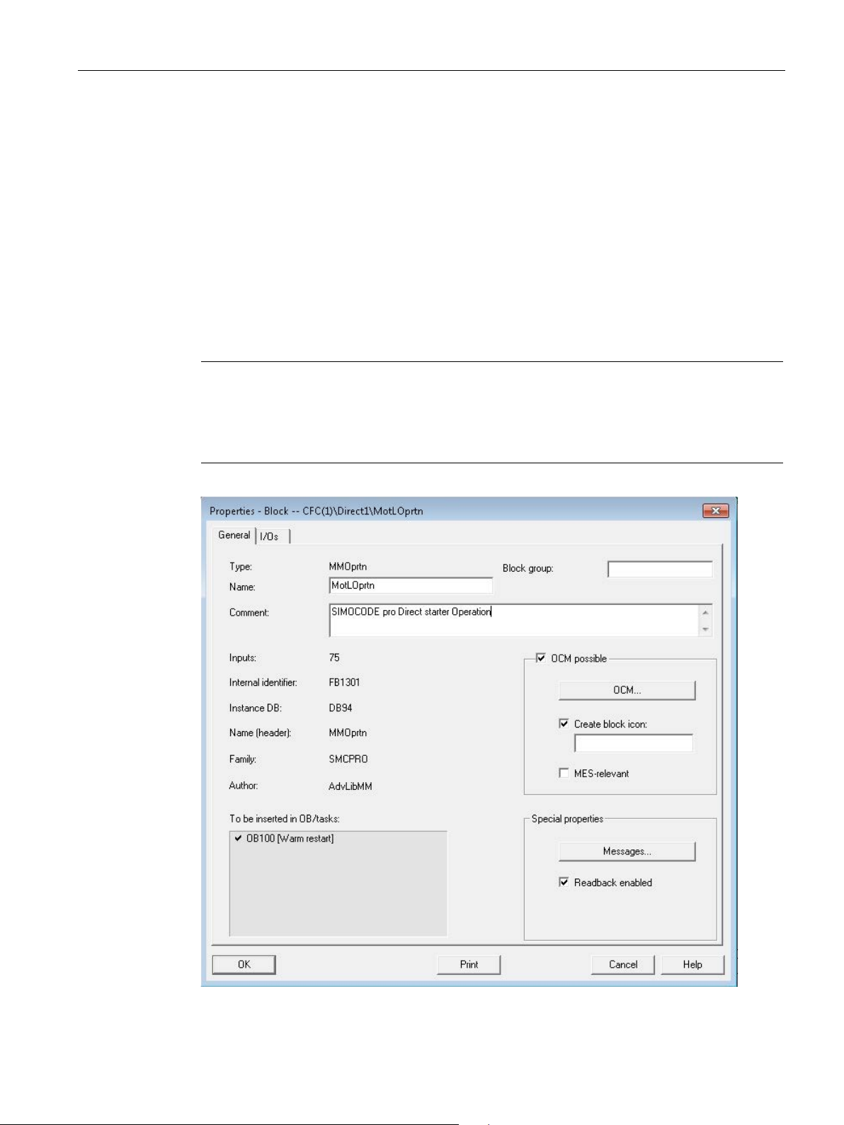
Once the OS compilation is al
template. The block icon will be that of the respective APL block. However, if the user
desires to have a block icon for the MMOprtn block, it can be enabled manually by the user
before OS compila
2.2 Using templates
The following blocks (CFC Sheet 2) are not absolutely necessary for operating SIMOCODE:
● MMMeas
● MMStat
● MMLog
They provide further functions such as measured values (e.g. temperature), statistical data,
and time stamping.
These blocks can be deleted (right mouse key → delete or select block → Del). After renewed
compiling and downloading to the PLC, these functionalities are no longer available for the
user program.
so done, there will be only one block icon created for each
tion. Refer to the screenshot below.
SIMOCODE pro PCS 7 Library V9.0
Programming and Operating Manual, 06/2017, A5E40899442002A/RS-AA/001
41
Page 42

Templates
2.3
Template OvlRly
Overload relay
•
•
•
•
•
Interconnections
Reference
2.3 Template OvlRly
This template supports the control function
It contains one instance each of the following blocks:
MMMeas
MMStat
MMLog
MMOprtn
1. Instantiate the template from the SIMOCODE pro Library and create the necessary links
to the respective blocks.
2. Assign the input address of the SIMOCODE pro device to the textual interconnection
"Input WORD address of SIMOCODE pro Module (IW x)" for linking the parameters
PZDIn01 (SIMOCODE blocks) / PZDIn1 (FbSwtMMS) with the logical address of the
starter. Input address and Output address should be maintained same while configuring.
Description of Blocks (Page 72)
Parameter (Page 234)
FbSwtMMS
.
SIMOCODE pro PCS 7 Library V9.0
42 Programming and Operating Manual, 06/2017, A5E40899442002A/RS-AA/001
Page 43

Templates
2.4
Template Direct
Direct starter
•
•
•
•
•
•
•
Interconnections
Reference
2.4 Template Direct
This template supports the control function
It contains one instance each of the following blocks:
MMOprtn
MMMeas
MMStat
MMLog
1. Instantiate the template from the SIMOCODE pro Library.
2. Assign the input address of the SIMOCODE pro device to the textual interconnection
"Input WORD address of SIMOCODE pro Module (IW x)" for linking the parameters
PZDIn01 (SIMOCODE blocks) / PZDIn1 (FbSwtMMS) with the logical address of the
starter. Input address and Output address should be maintained same while configuring.
Description of Blocks (Page 72)
Parameter (Page 234)
MotL
FbSwtMMS
Event16Ts
.
SIMOCODE pro PCS 7 Library V9.0
Programming and Operating Manual, 06/2017, A5E40899442002A/RS-AA/001
43
Page 44

Templates
2.5
Template Reverse
Reversing starter
•
•
•
•
•
•
•
Interconnections
Reference
2.5 Template Reverse
This template supports the control function
It contains one instance each of the following blocks:
MMOprtn
MMMeas
MMStat
MMLog
1. Instantiate the template from the SIMOCODE pro Library.
2. Assign the input address of the SIMOCODE pro device to the textual interconnection
"Input WORD address of SIMOCODE pro Module (IW x)" for linking the parameters
PZDIn01 (SIMOCODE blocks) / PZDIn1 (FbSwtMMS) with the logical address of the
starter. Input address and Output address should be maintained same while configuring.
Description of Blocks (Page 72)
Parameter (Page 234)
MotRevL
FbSwtMMS
Event16Ts
.
SIMOCODE pro PCS 7 Library V9.0
44 Programming and Operating Manual, 06/2017, A5E40899442002A/RS-AA/001
Page 45

Templates
2.6
Template MCCB
Circuit breaker
•
•
•
•
•
•
•
Interconnections
Reference
2.6 Template MCCB
This template supports the control function
It contains one instance each of the following blocks:
MMOprtn
MMMeas
MMStat
MMLog
1. Instantiate the template from the SIMOCODE pro Library.
2. Assign the input address of the SIMOCODE pro device to the textual interconnection
"Input WORD address of SIMOCODE pro Module (IW x)" for linking the parameters
PZDIn01 (SIMOCODE blocks) / PZDIn1 (FbSwtMMS) with the logical address of the
starter. Input address and Output address should be maintained same while configuring.
Description of Blocks (Page 72)
Parameter (Page 234)
MotL
FbSwtMMS
Event16Ts
.
SIMOCODE pro PCS 7 Library V9.0
Programming and Operating Manual, 06/2017, A5E40899442002A/RS-AA/001
45
Page 46

Templates
2.7
Template StarDel
Star-delta starter
•
•
•
•
•
•
•
Interconnections
Reference
2.7 Template StarDel
This template supports the control function
It contains one instance each of the following blocks:
MMOprtn
MMMeas
MMStat
MMLog
1. Instantiate the template from the SIMOCODE pro Library.
2. Assign the input address of the SIMOCODE pro device to the textual interconnection
"Input WORD address of SIMOCODE pro Module (IW x)" for linking the parameters
PZDIn01 (SIMOCODE blocks) / PZDIn1 (FbSwtMMS) with the logical address of the
starter. Input address and Output address should be maintained same while configuring.
Description of Blocks (Page 72)
Parameter (Page 234)
MotL
FbSwtMMS
Event16Ts
.
SIMOCODE pro PCS 7 Library V9.0
46 Programming and Operating Manual, 06/2017, A5E40899442002A/RS-AA/001
Page 47

Templates
2.8
Template RevStarDel
Star-delta reversing starter
•
•
•
•
•
•
•
Interconnections
Reference
2.8 Template RevStarDel
This template supports the control function
It contains one instance each of the following blocks:
MMOprtn
MMMeas
MMStat
MMLog
1. Instantiate the template from the SIMOCODE pro Library.
2. Assign the input address of the SIMOCODE pro device to the textual interconnection
"Input WORD address of SIMOCODE pro Module (IW x)" for linking the parameters
PZDIn01 (SIMOCODE blocks) / PZDIn1 (FbSwtMMS) with the logical address of the
starter. Input address and Output address should be maintained same while configuring.
Description of Blocks (Page 72)
Parameter (Page 234)
MotRevL
FbSwtMMS
Event16Ts
.
SIMOCODE pro PCS 7 Library V9.0
Programming and Operating Manual, 06/2017, A5E40899442002A/RS-AA/001
47
Page 48

Templates
2.9
Template Dahland
Dahlander
•
•
•
•
•
•
•
Interconnections
Reference
2.9 Template Dahland
This template supports the control function
MMOprtn
MMMeas
MMStat
MMLog
1. Instantiate the template from the SIMOCODE pro Library.
2. Assign the input address of the SIMOCODE pro device to the textual interconnection
"Input WORD address of SIMOCODE pro Module (IW x)" for linking the parameters
PZDIn01 (SIMOCODE blocks) / PZDIn1 (FbSwtMMS) with the logical address of the
starter. Input address and Output address should be maintained same while configuring.
Description of Blocks (Page 72)
Parameter (Page 234)
MotSpdL
FbSwtMMS
Event16Ts
.
SIMOCODE pro PCS 7 Library V9.0
48 Programming and Operating Manual, 06/2017, A5E40899442002A/RS-AA/001
Page 49

Templates
2.10
Template RevDahl
Dahlander reversing starter
•
•
•
•
•
•
•
Interconnections
Reference
2.10 Template RevDahl
This template supports the control function
MMOprtn
MMMeas
MMStat
MMLog
1. Instantiate the template from the SIMOCODE pro Library.
2. Assign the input address of the SIMOCODE pro device to the textual interconnection
"Input WORD address of SIMOCODE pro Module (IW x)" for linking the parameters
PZDIn01 (SIMOCODE blocks) / PZDIn1 (FbSwtMMS) with the logical address of the
starter. Input address and Output address should be maintained same while configuring.
Description of Blocks (Page 72)
Parameter (Page 234)
MMRevDhl
FbSwtMMS
Event16Ts
.
SIMOCODE pro PCS 7 Library V9.0
Programming and Operating Manual, 06/2017, A5E40899442002A/RS-AA/001
49
Page 50

Templates
2.11
Template PoleChng
Pole-changing starter
•
•
•
•
•
•
•
Interconnections
Reference
2.11 Template PoleChng
This template supports the control function
MMOprtn
MMMeas
MMStat
MMLog
1. Instantiate the template from the SIMOCODE pro Library.
2. Assign the input address of the SIMOCODE pro device to the textual interconnection
"Input WORD address of SIMOCODE pro Module (IW x)" for linking the parameters
PZDIn01 (SIMOCODE blocks) / PZDIn1 (FbSwtMMS) with the logical address of the
starter. Input address and Output address should be maintained same while configuring.
Description of Blocks (Page 72)
Parameter (Page 234)
MotSpdL
FbSwtMMS
Event16Ts
.
SIMOCODE pro PCS 7 Library V9.0
50 Programming and Operating Manual, 06/2017, A5E40899442002A/RS-AA/001
Page 51

Templates
2.12
Template RevPoleCh
Pole-changing reversing starter
•
•
•
•
•
•
•
Interconnections
Reference
2.12 Template RevPoleCh
This template supports the control function
MMOprtn
MMMeas
MMStat
MMLog
1. Instantiate the template from the SIMOCODE pro Library.
2. Assign the input address of the SIMOCODE pro device to the textual interconnection
"Input WORD address of SIMOCODE pro Module (IW x)" for linking the parameters
PZDIn01 (SIMOCODE blocks) / PZDIn1 (FbSwtMMS) with the logical address of the
starter. Input address and Output address should be maintained same while configuring.
Description of Blocks (Page 72)
Parameter (Page 234)
MMRevDhl
FbSwtMMS
Event16Ts
.
SIMOCODE pro PCS 7 Library V9.0
Programming and Operating Manual, 06/2017, A5E40899442002A/RS-AA/001
51
Page 52

Templates
2.13
Template SolValve
Solenoid valve
•
•
•
•
•
•
•
Interconnections
Reference
2.13 Template SolValve
This template supports the control function
MMOprtn
MMMeas
MMStat
MMLog
1. Instantiate the template from the SIMOCODE pro Library.
2. Assign the input address of the SIMOCODE pro device to the textual interconnection
"Input WORD address of SIMOCODE pro Module (IW x)" for linking the parameters
PZDIn01 (SIMOCODE blocks) / PZDIn1 (FbSwtMMS) with the logical address of the
starter. Input address and Output address should be maintained same while configuring.
Description of Blocks (Page 72)
Parameter (Page 234)
VlvL
FbSwtMMS
Event16Ts
.
SIMOCODE pro PCS 7 Library V9.0
52 Programming and Operating Manual, 06/2017, A5E40899442002A/RS-AA/001
Page 53

Templates
2.14
Template Positner
Positioner
•
•
•
•
•
•
•
Interconnections
Reference
2.14 Template Positner
This template supports the control function
MMOprtn
MMMeas
MMStat
MMLog
1. Instantiate the template from the SIMOCODE pro Library.
2. Assign the input address of the SIMOCODE pro device to the textual interconnection
"Input WORD address of SIMOCODE pro Module (IW x)" for linking the parameters
PZDIn01 (SIMOCODE blocks) / PZDIn1 (FbSwtMMS) with the logical address of the
starter. Input address and Output address should be maintained same while configuring.
Description of Blocks (Page 72)
Parameter (Page 234)
VlvMotL
FbSwtMMS
Event16Ts
.
SIMOCODE pro PCS 7 Library V9.0
Programming and Operating Manual, 06/2017, A5E40899442002A/RS-AA/001
53
Page 54

Templates
2.15
Template SoftStr
Soft starter
•
•
•
•
•
•
•
Interconnections
Reference
2.15 Template SoftStr
This template supports the control function
MMOprtn
MMMeas
MMStat
MMLog
1. Instantiate the template from the SIMOCODE pro Library.
2. Assign the input address of the SIMOCODE pro device to the textual interconnection
"Input WORD address of SIMOCODE pro Module (IW x)" for linking the parameters
PZDIn01 (SIMOCODE blocks) / PZDIn1 (FbSwtMMS) with the logical address of the
starter. Input address and Output address should be maintained same while configuring.
Description of Blocks (Page 72)
Parameter (Page 234)
MotL
FbSwtMMS
Event16Ts
.
SIMOCODE pro PCS 7 Library V9.0
54 Programming and Operating Manual, 06/2017, A5E40899442002A/RS-AA/001
Page 55

Templates
2.16
Template RevSoftStr
Soft reversing starter
•
•
•
•
•
•
•
Interconnections
Reference
2.17
Sample Project
Sample Project
Note
The Direct template, when used from the templates of the Library will not have the blocks
MonDi08 and W_BO and the
2.16 Template RevSoftStr
This template supports the control function
MMOprtn
MMMeas
MMStat
MMLog
1. Instantiate the template from the SIMOCODE pro Library.
2. Assign the input address of the SIMOCODE pro device to the textual interconnection
"Input WORD address of SIMOCODE pro Module (IW x)" for linking the parameters
PZDIn01 (SIMOCODE blocks) / PZDIn1 (FbSwtMMS) with the logical address of the
starter. Input address and Output address should be maintained same while configuring.
Description of Blocks (Page 72)
Parameter (Page 234)
MotRevL
FbSwtMMS
Event16Ts
.
A sample project with SIMOCODE pro PCS7 Library V9.0 is provided along with the
installation at the path - \Siemens\Step7\Examples\Simo_Prj.
This sample project serves as an example for how to use the blocks of the Library. The
template Direct is used in the CFC Charts of the sample project as an example for
configuration.
The template is modified in the CFC Charts to access the Byte1 information of the Process
Image input of the configured Simocode device. This is realized by interconnecting the
Process image input value to the input signals of the MonDi08 (Block for the measurement
monitoring of 8 Binary signals) of APL, via a converter block, W_BO.
respective interconnections.
SIMOCODE pro PCS 7 Library V9.0
Programming and Operating Manual, 06/2017, A5E40899442002A/RS-AA/001
55
Page 56
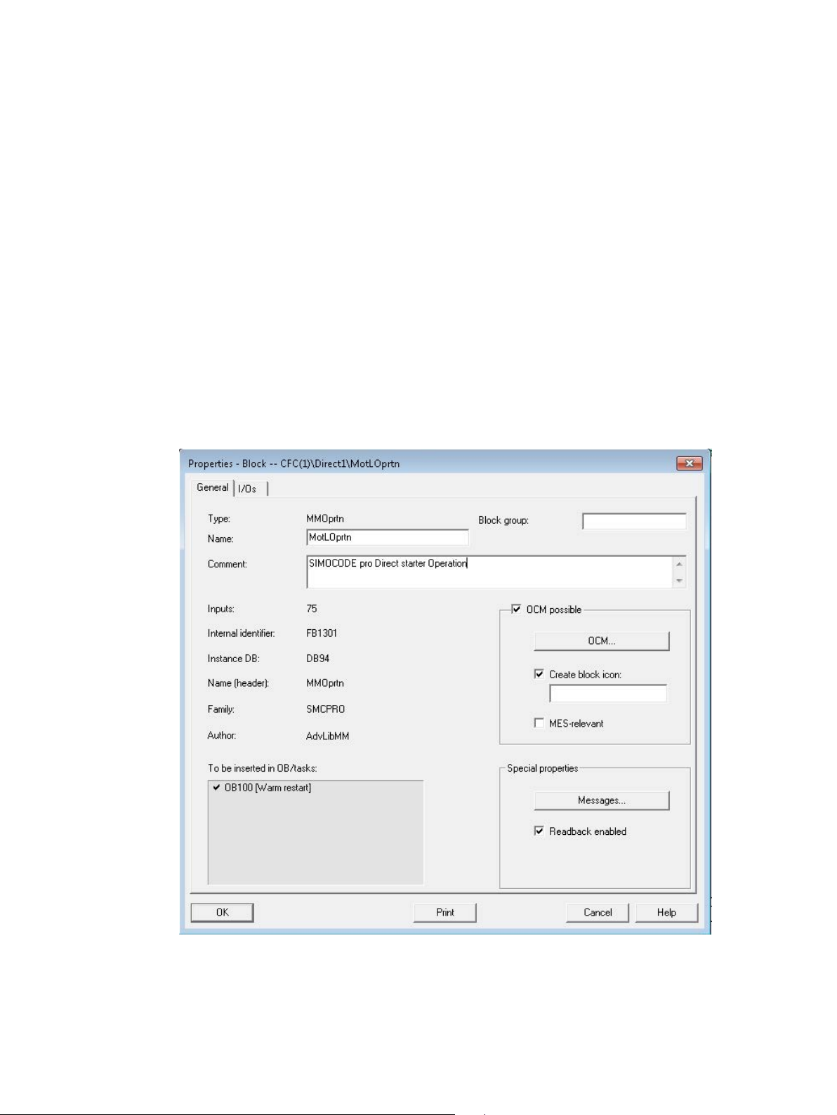
3
3.1
Block icons
Creating block icons in CFC
The MMRevDhl and MMOprtn blocks can each be displayed via various block icons.
To change/switch a block icon, enter the number for the appropriate block icon in the object
properties of the block (Input field underneath check box "Create block icon").
Refer to the following tables to retrieve the block icon number.
Clicking on the block icon opens the corresponding faceplate and the block icon remains
highlighted as long as this faceplate is opened.
Figure 3-1 Creating block icon
SIMOCODE pro PCS 7 Library V9.0
56 Programming and Operating Manual, 06/2017, A5E40899442002A/RS-AA/001
Page 57
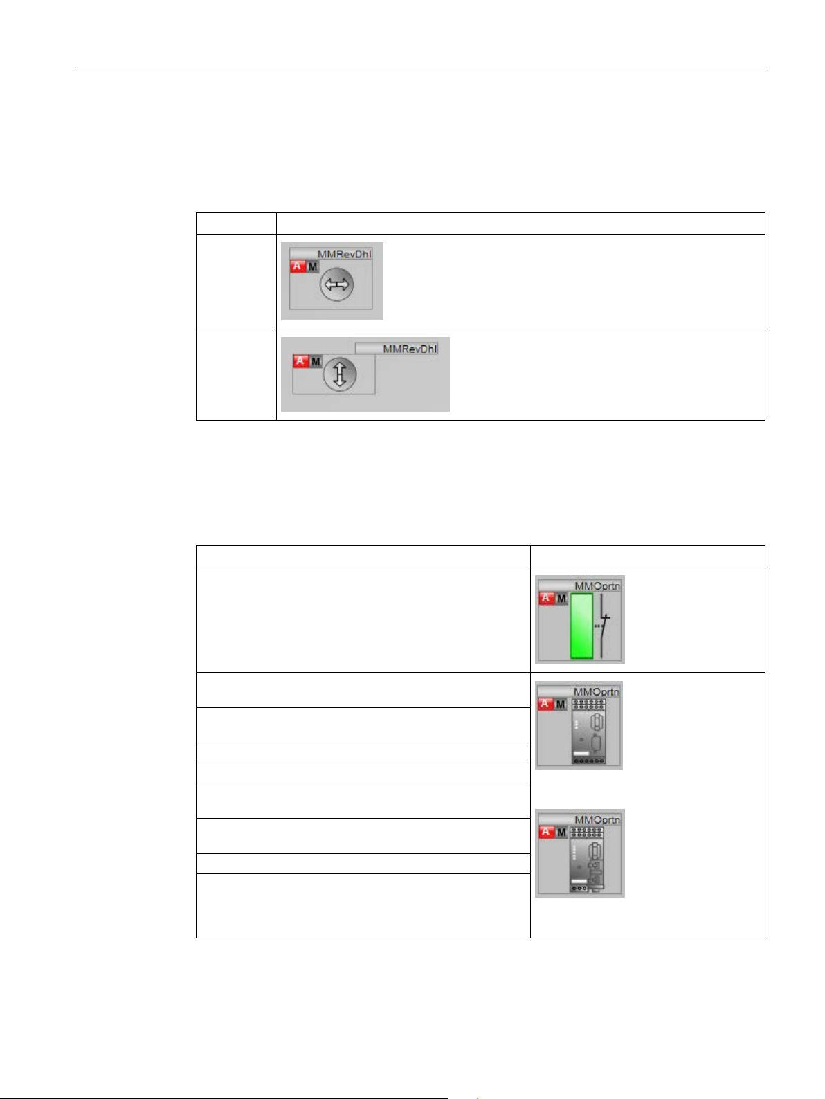
Block icons and faceplate views
MMRevDhl block icons
Number
Icon
MMOprtn block icons
SIMOCODE pro control function
Icon
soft starter
soft reversing starter
Star-delta starter
Star-delta reversing starter
pole-changing starter
Pole-changing reversing starter
Solenoid valve
3.1 Block icons
The MMRevDhl block provides 2 block icons.
Table 3- 1 MMRevDhl block icons
1
2
The MMOprtn block provides the following block icons:
Table 3- 2 MMOprtn block icons
Overload relay
Direct starter /
Reversing starter /
Dahlander /
Dahlander reversing starter /
PROFIBUS
SIMOCODE pro PCS 7 Library V9.0
Programming and Operating Manual, 06/2017, A5E40899442002A/RS-AA/001
Positioners 1-5
PROFINET
The status display at the block icon depends upon the final status of the drive, but not on the
feedback received from the drive.
57
Page 58
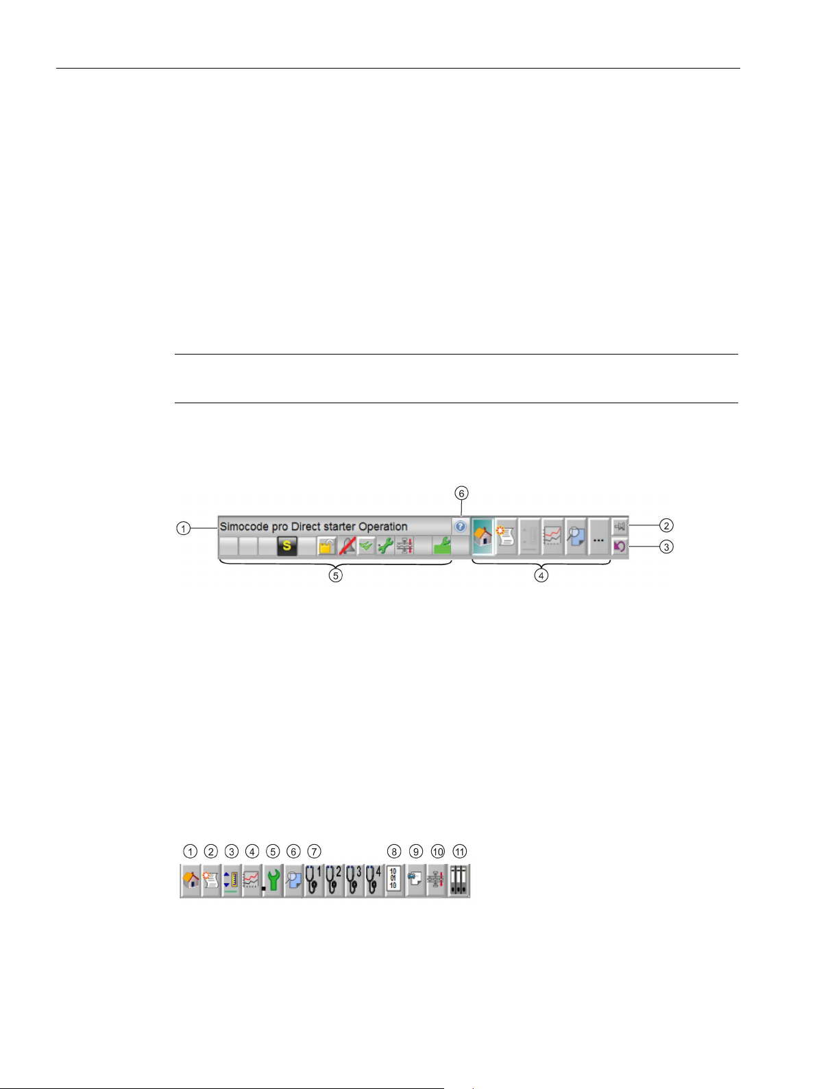
Block icons and faceplate views
3.2
Faceplates
3.2.1
Faceplates - Structure
Note
WinCC tools can be used to make necessary modif
Structure of a faceplate
①
Comments, e.g., name of starter
②
You can use this button to secure the faceplate when switching the range.
③
You can use this button to return to the original process picture.
④
Right clicking on an icon opens the selected view in a separate window.
⑤
Overview window
⑥
Help button
Icons
①
Standard
⑤
Maintenance
⑨
Memo
②
Alarm
⑥
Preview
⑩
Batch
③
Limits
⑦
Diagnostics
⑪
Logbook
④
Trend
⑧
Process image
3.2 Faceplates
A faceplate displays all the elements of a block graphically. The faceplate is displayed in a
separate window on the Operator Station (OS). You can call the faceplate:
● Using picture selection keys
● From the process tag list
● By clicking the specific block icon
ications to the faceplates.
"Pin faceplate" button:
"Back to Process" button:
Toolbar for selecting the availible views for the relevant block.
SIMOCODE pro PCS 7 Library V9.0
58 Programming and Operating Manual, 06/2017, A5E40899442002A/RS-AA/001
Page 59
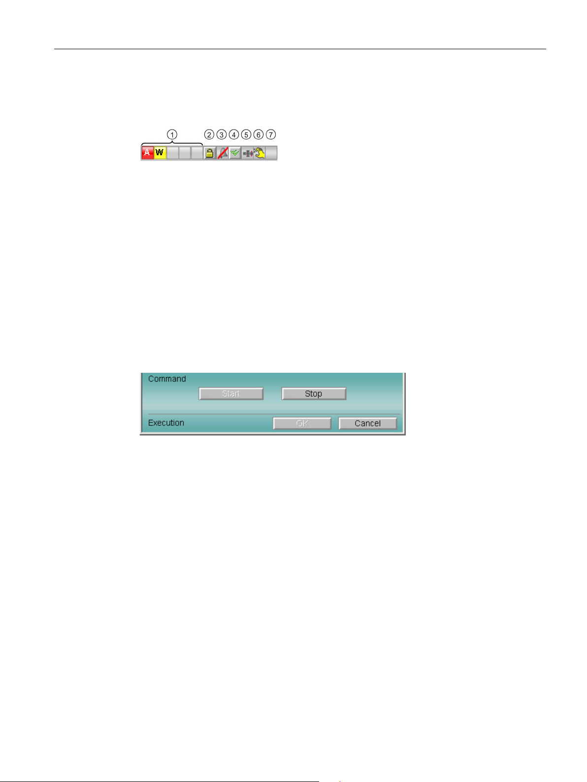
Block icons and faceplate views
Overview window
①
Indicates whether unacknowledged alarms and warnings are pending.
②
LOCK status for messages, authorization level 5 and higher
③
Message suppression
④
Message acknowledgement, authorization level 5 and higher
⑤
This function indicates whether the block instance of SIMATIC BATCH is assigned.
⑥
Signal status of the block
⑦
Reserved
Expanded command area
3.2 Faceplates
The overview window shows the overall status of the block:
Group display:
Occupied - Batch:
For inputs in the dialog window that require confirmation by the operator, the command area
is expanded in the faceplate. The corresponding options are then available, depending on
the selection.
Figure 3-2 Example of expanded command area
The expanded command area can be programmed with a 2- or 3-level access concept for
the operator. The access can be changed in the WinCC Explorer using the internal
@APLCommandExecutionSteps variable.
Level 2: The operator only needs to press the command to execute.
Level 3: The operator must also press the OK button to execute the command.
SIMOCODE pro PCS 7 Library V9.0
Programming and Operating Manual, 06/2017, A5E40899442002A/RS-AA/001
59
Page 60
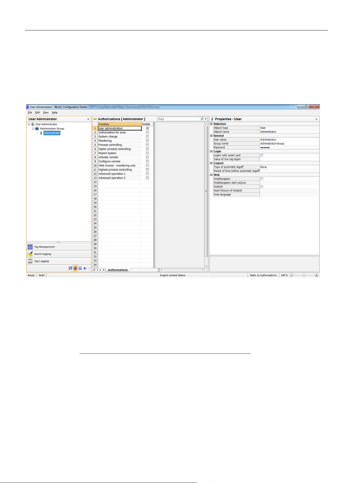
Block icons and faceplate views
Authorization levels
Reference
3.2 Faceplates
Some commands are subject to permission with authorization levels via WinCC. The
authorization levels are updated when a view is opened. The user can only execute the
commands that are enabled for him.
The authorization levels are created for the project by means of a user ID.
Figure 3-3 Assigning authorization levels in WinCC
The configuration of faceplates and icons follow the standards of the Advanced Process
Library.
For more information about this and authorization levels, refer to Function Manual "Process
Control System PCS7, PCS7 Advanced Process Library V9" on the Internet
(https://support.industry.siemens.com/cs/ww/en/view/109482346
).
SIMOCODE pro PCS 7 Library V9.0
60 Programming and Operating Manual, 06/2017, A5E40899442002A/RS-AA/001
Page 61
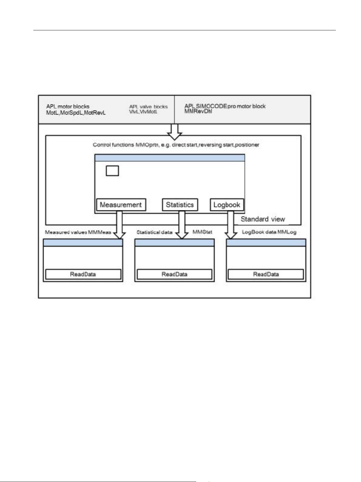
Block icons and faceplate views
3.2.2
Navigation between SIMOCODE pro faceplates
Navigation between SIMOCODE pro faceplates
3.2 Faceplates
Figure 3-4 PCS7 APL
SIMOCODE pro PCS 7 Library V9.0
Programming and Operating Manual, 06/2017, A5E40899442002A/RS-AA/001
61
Page 62
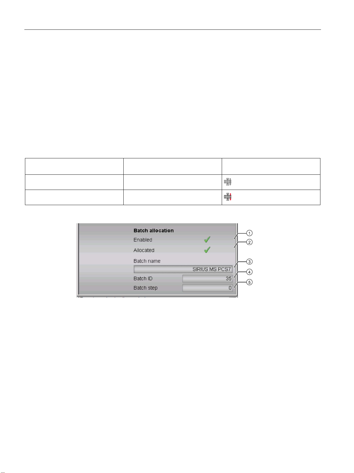
Block icons and faceplate views
3.2 Faceplates
3.2.3 Views
3.2.3.1 Batch view
The "Batch" view is available in the MMRevDhl, MMOprtn, MMStat, MMMeas and MMLog
blocks.
Batch view
This area shows a display of the batch that is currently running (Batchview).
You can use the internal tag "@APLBatchEnable" to enable/disable the "Batch" button in the
toolbar.
Value of @APLBatchEnable Operating the "Batch" button in the
toolbar
0 Disabled
Icon of the "Batch" button in the toolbar
1* Enabled
*Batch ID has to be greater than 0 for Batch to be enabled.
① Enabled
(BatchEn)
② Allocated
(Occupied)
③ Batch name
(BatchName)
④ Batch ID
(BatchID)
⑤ Batch step
(StepNo)
This area shows you if the block is enabled for operation via SIMATIC BATCH
(Status1.Bit1)
This area shows if the block is currently in use by SIMATIC BATCH
(Status1.Bit0)
This area shows the name of the batch that is currently running
This area shows the identification number of the batch that is currently running
(BatchID).
The batch view is disabled if
This area shows the step number of the batch that is currently running.
BatchID = 16#00000000.
SIMOCODE pro PCS 7 Library V9.0
62 Programming and Operating Manual, 06/2017, A5E40899442002A/RS-AA/001
Page 63
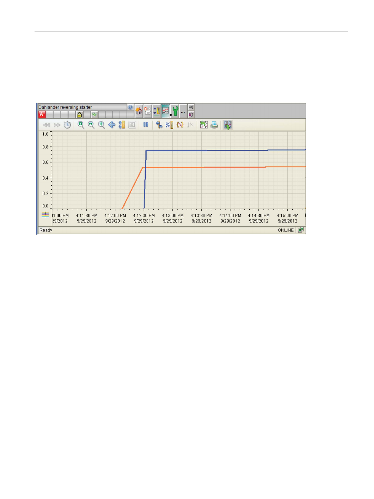
Block icons and faceplate views
3.2 Faceplates
3.2.3.2 Trend view
The "Trend" view is available in the MMRevDhl, MMOprtn and MMMeas blocks.
Trend view
Configuring the view
The block parameters that are evaluated for the trend are configured in the block icon of the
block.
To configure the view, use the TrendPictureName, TrendConfiguration and Trend colour
properties. Up to 10 parameters can be used for the view.
1. The file name TrendPictureName for MMOprtn and MMMeas is: "@PG_APL_Trend.PDL",
2. TrendConfiguration is entered in the following format:
3. Trend colour determines the color of the curve.
for MMRevDhl "@PG_APL_Trendbin.PDL".
<ParameterName>;<TrendControl>;<Reserved>;<Name of the Curve>
e.g. MotCurr#Value;_TrendCtrl1_;Reserved;MotorCurrent
SIMOCODE pro PCS 7 Library V9.0
Programming and Operating Manual, 06/2017, A5E40899442002A/RS-AA/001
63
Page 64
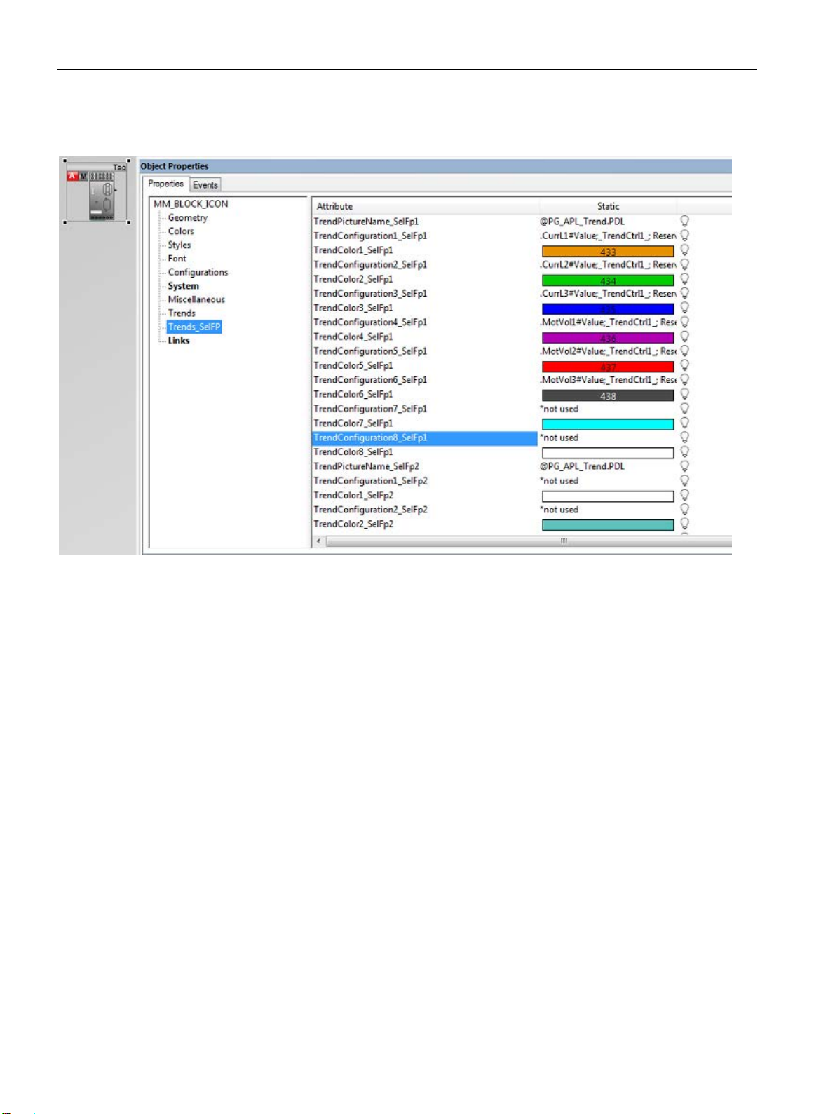
Block icons and faceplate views
3.2 Faceplates
Object properties TrendConfiguration
Trends Trend curves configuration for the MMOprtn block
Trends_SelFp1 Trend curves configuration for the block connected via the parameter Trends_SelFp1 (e.g.
MMMeas).
Trends_SelFp2 Trend curves configuration for the block connected via the parameter Trends_SelFp2.
Figure 3-5 Object properties TrendConfiguration
SIMOCODE pro PCS 7 Library V9.0
64 Programming and Operating Manual, 06/2017, A5E40899442002A/RS-AA/001
Page 65
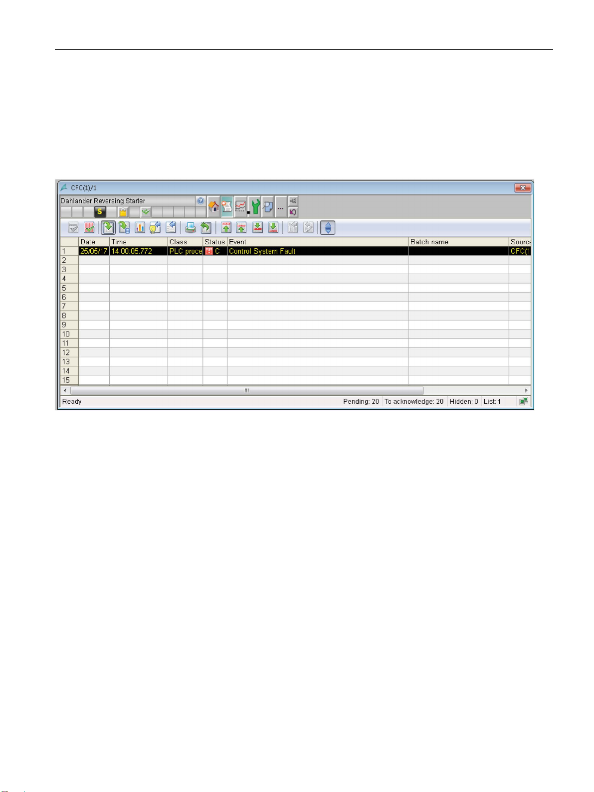
Block icons and faceplate views
3.2 Faceplates
3.2.3.3 Alarm view
The "Alarm" view is available in the MMRevDhl, MMOprtn, MMMeas, MMStat and MMLog
blocks.
Alarm view
Figure 3-6 Alarm view – example of MMRevDhl block
SIMOCODE pro PCS 7 Library V9.0
Programming and Operating Manual, 06/2017, A5E40899442002A/RS-AA/001
65
Page 66
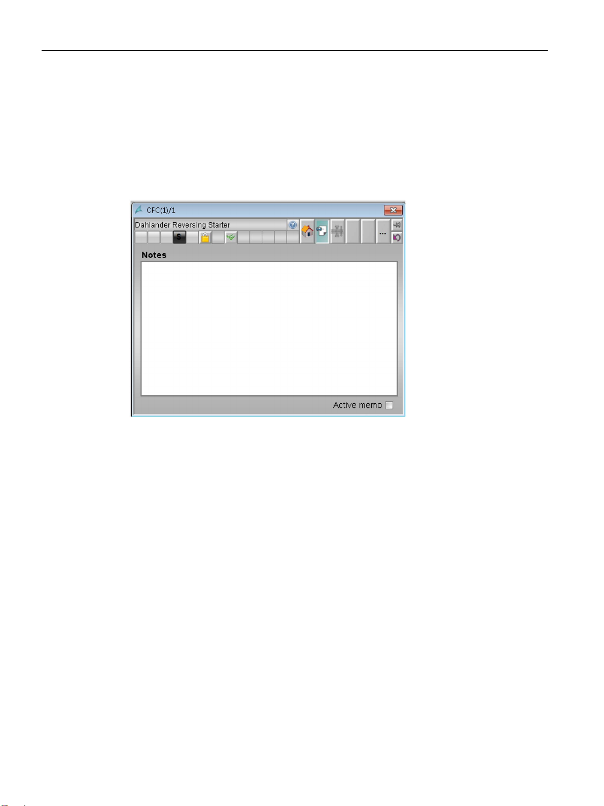
Block icons and faceplate views
3.2 Faceplates
3.2.3.4 Memo view
In the "Memo" view, you can leave temporary messages for other OS operators. You enter
them in the input field and store them by selecting the "Active memo checkbox."
The "Memo" view is available in the MMRevDhl block.
Memo view
The next time the faceplate is opened and the process display is changed, the user will be
informed in the status line of the block icon and the faceplate that a new message exists.
Deselecting the checkbox clears the displays on the status lines.
SIMOCODE pro PCS 7 Library V9.0
66 Programming and Operating Manual, 06/2017, A5E40899442002A/RS-AA/001
Page 67
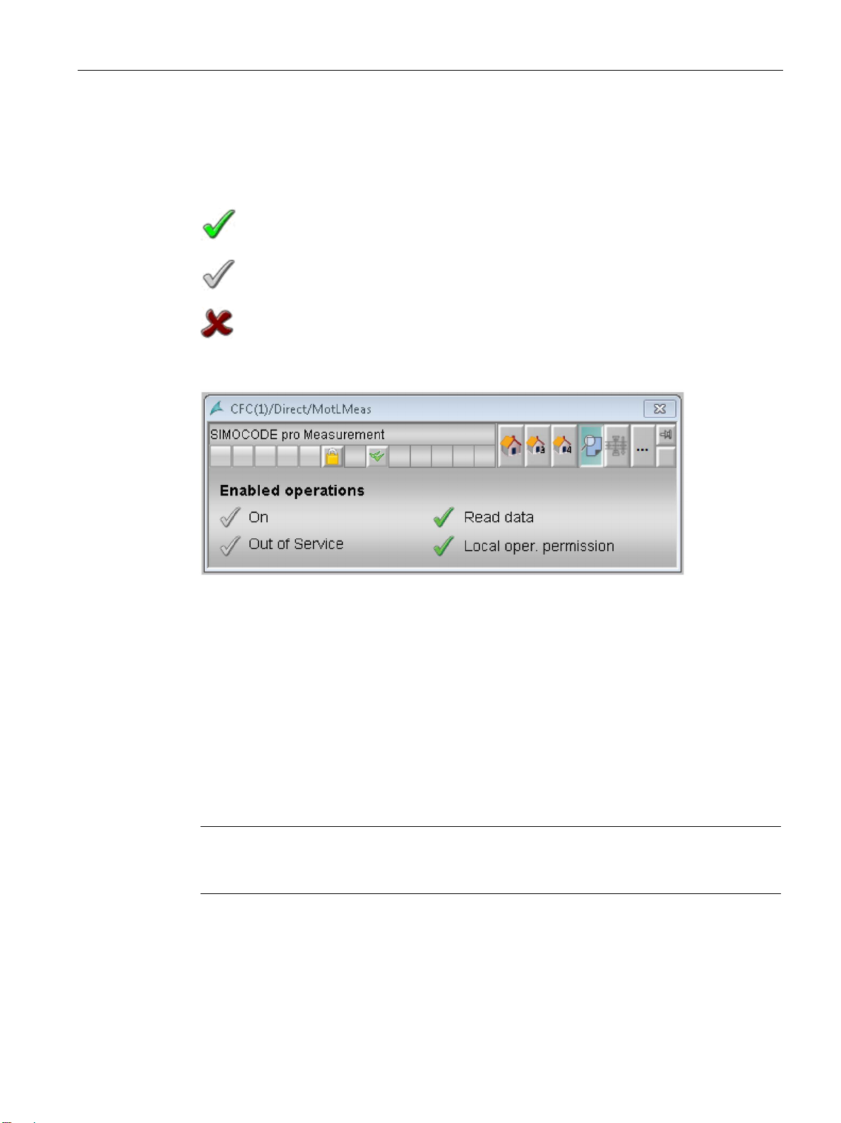
Block icons and faceplate views
3.2 Faceplates
3.2.3.5 Preview view
The preview view shows the operator permissions for each signal block.
The commands for which the operator permissions are shown depend on the block.
The operator may execute the command.
The operator may e
process in the block.
The operator is not permitted to ex
Figure 3-7 Preview view – example of MMMeas
3.2.4 Scalable faceplates
xecute the command. The command is currently blocked by a
ecute the command.
The faceplates will be scaled from 50% to 200%. The value to scale will be given in the
internal variable "@APLFaceplateScaleFactor". Default value is 100. The faceplates will be
scaled up from 101% to 200%, by providing a value in a range of 101-200 in internal
variable. Similarly the faceplates will be scaled down from 50% to 99% , by providing a value
in the range 50-99. The reference for calculation is default size of the faceplates which is
100(%). It means if the value given is 150, the faceplates will be scaled up by 50% of the
default size.
Note
Faceplate must be reopened after changing the scale value. Already opened faceplate
cannot be scaled up if the scale value is changed.
SIMOCODE pro PCS 7 Library V9.0
Programming and Operating Manual, 06/2017, A5E40899442002A/RS-AA/001
67
Page 68
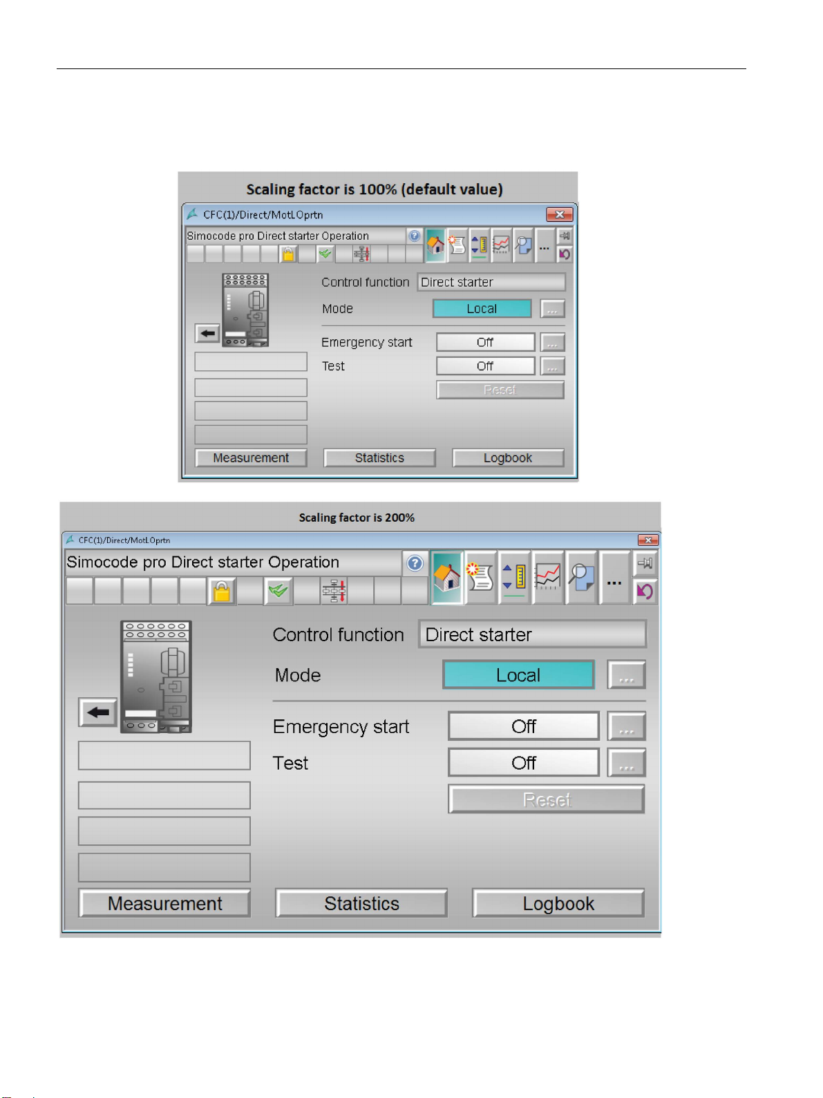
Block icons and faceplate views
3.2 Faceplates
Example: The screenshot below shows the faceplates scaled up by providing the value of
200, scaled down by providing the value of 50 for the internal variable.
SIMOCODE pro PCS 7 Library V9.0
68 Programming and Operating Manual, 06/2017, A5E40899442002A/RS-AA/001
Page 69
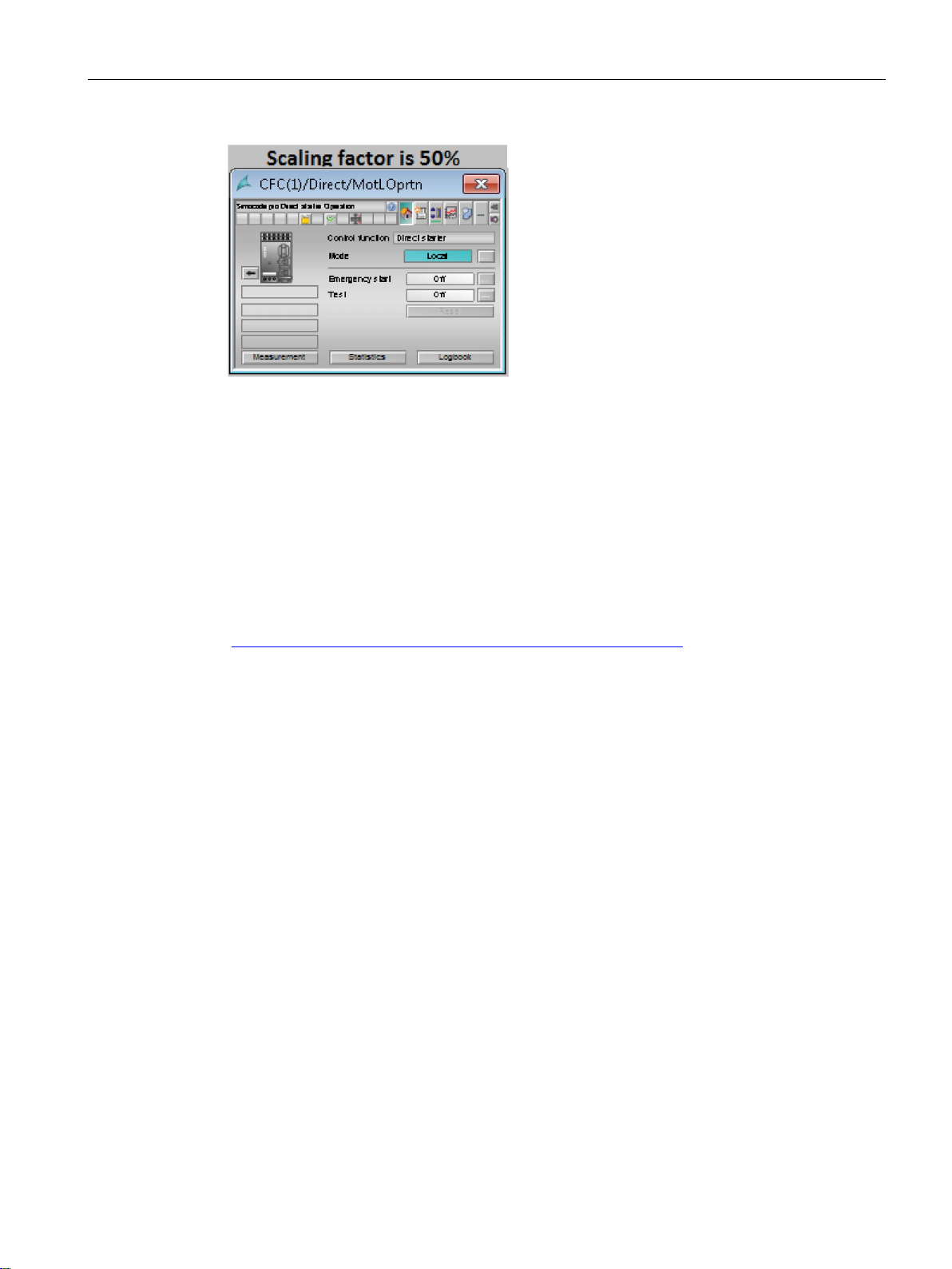
Block icons and faceplate views
3.3
Central color management
3.3 Central color management
The central color palette from the APL Library underlies the "SIMOCODE pro PCS 7 Library
V9.0".
The colors in the faceplates and block icons can be changed via this central color palette in
WinCC. The color palette is located on the "User interface and design" tab of the project
properties.
For more information about the parameterizable functions, refer to the Function Manual
"Process Control System PCS 7, PCS 7 Advanced Process Library V9.0" on the Internet
(https://support.industry.siemens.com/cs/ww/en/view/109482346
).
SIMOCODE pro PCS 7 Library V9.0
Programming and Operating Manual, 06/2017, A5E40899442002A/RS-AA/001
69
Page 70
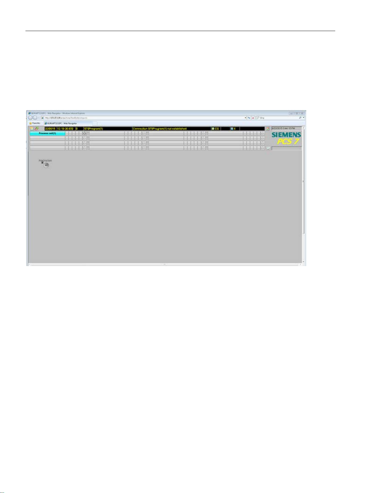
Block icons and faceplate views
3.4
Web Navigator
3.4 Web Navigator
The SIMOCODE pro PCS 7 Library V9.0 supports the Web Navigator functions.
You will find further information on configuring the Web Navigator functions in the manual
"PCS 7 - OS Web Option" under C:\Program
Files\SIEMENS\Documentation\Manuals\English.
Figure 3-8 Web Navigator
SIMOCODE pro PCS 7 Library V9.0
70 Programming and Operating Manual, 06/2017, A5E40899442002A/RS-AA/001
Page 71
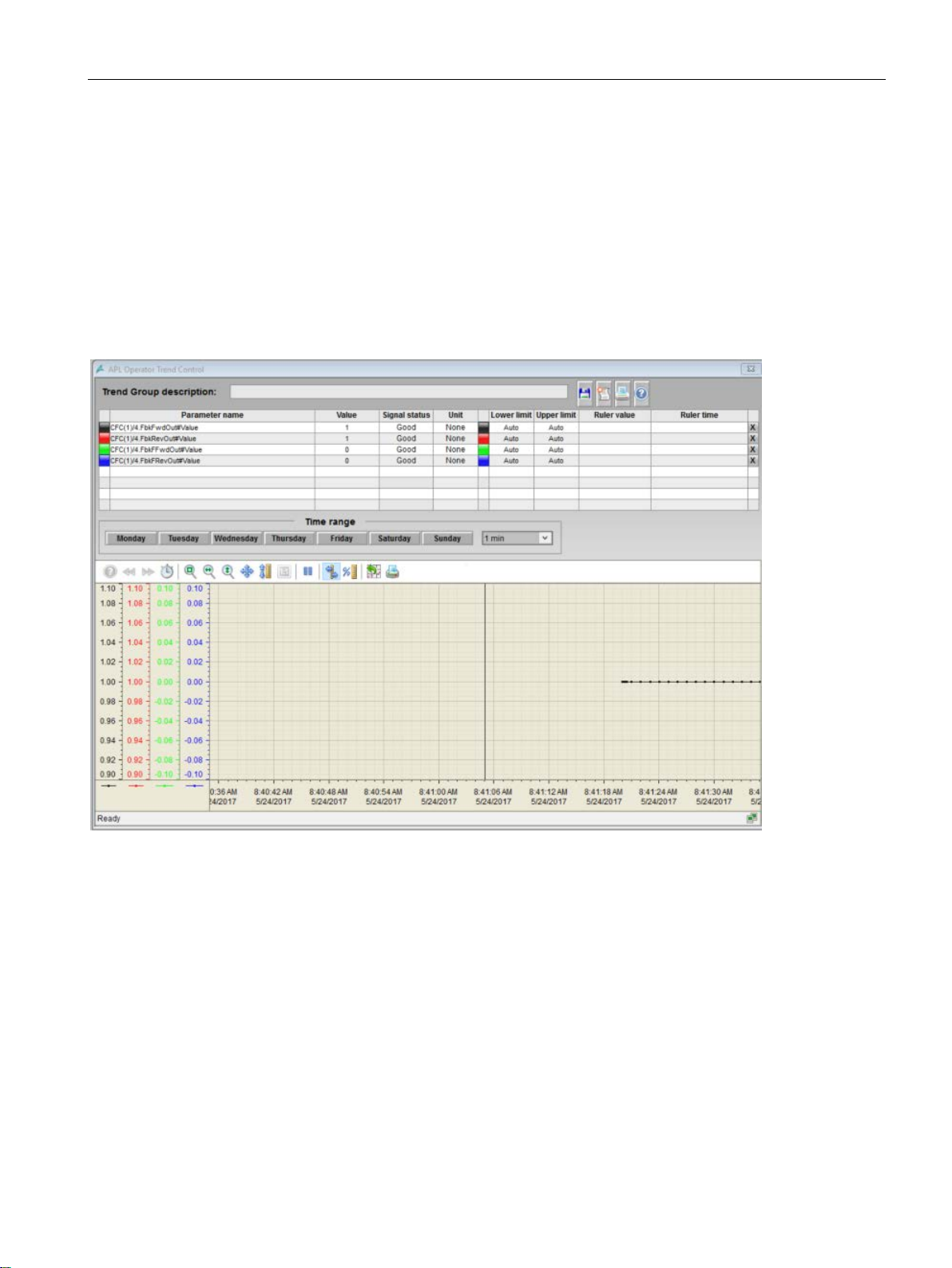
Block icons and faceplate views
3.5
APL Operator Trend Control (AOTC) for Digital Values
.
3.5 APL Operator Trend Control (AOTC) for Digital Values
Opening the AOTC window
Press and hold the Ctrl key and left-click the value on the block icon to open the AOTC
window. Status of parameters (FbkFFwdOut, FbkFwdOut, FbkFRevOut and FbkRevOut) are
added to the Trend Control and the detailed information is displayed in the each row of the
overview area
Figure 3-9 AOTC window
For more information on Operator Trend Control (AOTC)
SIMOCODE pro PCS 7 Library V9.0
Programming and Operating Manual, 06/2017, A5E40899442002A/RS-AA/001
71
Page 72

4
4.1
Functions for all blocks
4.1.1
Calling OBs
OB
Description
MMDiag
MMMeas
MMStat
MMLog
MMRevDh
l
MMOprtn
OB1
Cyclic program
X – – – –
–
OB30...OB381
Cyclic alarms
X X X X X
X
OB82
Diagnostics alarm
X – – – –
–
OB85
Program execution error
X – – – –
–
OB86
Rack fault
X – – – –
–
OB100
Restart (warm restart)
X X X X X
X
1
"X" = The OB calls the block, "–" = The OB does not call the block.
Reference
Table 4- 1 Organization blocks
The "Generate module driver" function automatically inserts a SIMOCODE pro block into the
following organization blocks within the run sequence of the CFC:
OB40 Process alarm X – – X – –
OB83 Insert/remove interrupt X – – – – –
Insert the block in OB32, if read/write access is slow.
You can obtain further information on the organization blocks in the "Process Control System
PCS 7 System Functions" manual and in the system and standard functions reference
manual for S7-300/400 on the internet
(https://support.industry.siemens.com/cs/document/44240604
).
SIMOCODE pro PCS 7 Library V9.0
72 Programming and Operating Manual, 06/2017, A5E40899442002A/RS-AA/001
Page 73

Description of the blocks
4.1.2
Called blocks
Block
Description
MMDiag
MMMeas
MMStat
MMLog
MMRevD
hl
MMOprtn
8 signals
SFB53
WRREC
Writes a data record
– – X – –
X
SFB54
RALRM
Receives alarm
X – – X –
X
mation
of the DP slave
SFC20
BLKMOV
Copying of tags
– X X X X
X
list or the sublist
SFC64
TIME_TCK
Reads the system time
X X – – –
X
signal status
"X" = The SIMOCODE pro block calls this block, "–" = the SIMOCODE pro block does not call this block.
4.1 Functions for all blocks
The SIMOCODE pro blocks call the following blocks:
Table 4- 2 Called blocks
SFB35 ALARM_8P Generates block-specific
messages with values for
SFB52 RDREC Reads a data record X X X X – X
SFC6 RD_SINFO Reading of OB start infor-
SFC13 DPNRM_DG Reads the diagnostic data
SFC51 RDSYSST Reads the system status
FC369 SelST16 Output of the best or worst
X X X X X X
X X X X X X
– – – – – X
X – – – – –
X X X X X X
SIMOCODE pro PCS 7 Library V9.0
Programming and Operating Manual, 06/2017, A5E40899442002A/RS-AA/001
73
Page 74

Description of the blocks
4.1.3
Worst signal status
Block
Parameter
FbkFwdOut.ST
FRevChnST.ST
ModF_Act.ST
WrErr.ST
ModF_Act.ST
RdDataLi.ST
ModF_Act.ST
RdDataLi.ST
ModF_Act.ST
RdErr.ST
ModF_Act.ST
RdDataLi.ST
4.1 Functions for all blocks
Worst Signal Status ST_Worst is formed from the following parameters:
MMRevDhl
MMOprtn
FbkRevOut.ST
FbkFFwdOut.ST
FbkFRevOut.ST
LocalLi.ST
FFwdLocal.ST
FwdLocal.ST
StopLocal.ST
RevLocal.ST
FRevLocal.ST
Trip.ST
FwdAut.ST
RevAut.ST
StopAut.ST
FFwdAut.ST
FRevAut.ST
FwdChnST.ST
RevChnST.ST
FFwdChnST.ST
RackF_Act.ST
GenFlt.ST
GenWarn.ST
EmrgStOn.ST
CstAut.ST
TrpRstLi.ST
RdDataLi.ST
GrpErr.ST
RdErr.ST
SIMOCODE pro PCS 7 Library V9.0
74 Programming and Operating Manual, 06/2017, A5E40899442002A/RS-AA/001
MMMeas
MMStat
MMDiag
MMLog
RackF_Act.ST
GrpErr.ST
RdErr.ST
RackF_Act.ST
GrpErr.ST
RdErr.ST
RackF_Act.ST
GrpErr.ST
Cst.ST
Rack1Err.ST
Rack2Err.ST
RackF_Act.ST
RdErr.ST
Page 75

Description of the blocks
4.1.4
Quality code
Quality
Code
Priority 1
Occurs when...
Meaning
MMDiag
MMMeas
MMStat
MMLog
MMRevDhl
MMOprtn
16#80
6
No error
Good X X – X
X
SimOn
0
BusFlt
X X
blocks
specific
device-specific
demand
16#FF
–
Default setting
– – X – –
–
1
"X"= The Quality Code occurs in this block, "–" = The quality code does not occur in this block.
4.1 Functions for all blocks
The process values of the function blocks are generated and transferred along with a signal
status as a structured variable. This contains a statement about the signal quality. The
function blocks determine the appropriate signal status for their process outputs depending
on the signal status of the process inputs. The signal status is formed from the input
parameters according to the priority table below (highest priority is 0). This group status is
displayed in the status bar of the faceplate and of the block icon. The signal status is
displayed for each individual parameter in the faceplate next to the process values.
Table 4- 3 Quality Code
16#60 –
16#00
16#28 1
16#28 2 From preceding
16#68 3 General warning Uncertain,
16#A4 – Maintenance
highest priority is 0
• RackF_Act
1 X X X
ModF_Act
•
•
• Subnet error
• OB not load-
Rack1Err or
Rack2Err
ed.
Simulated
value
Bad, devicespecific, value
not valid
Bad, devicespecific
Bad, process-
– – – X –
X – – – –
– X – X X
X – – X X
– – – X –
SIMOCODE pro PCS 7 Library V9.0
Programming and Operating Manual, 06/2017, A5E40899442002A/RS-AA/001
75
Page 76
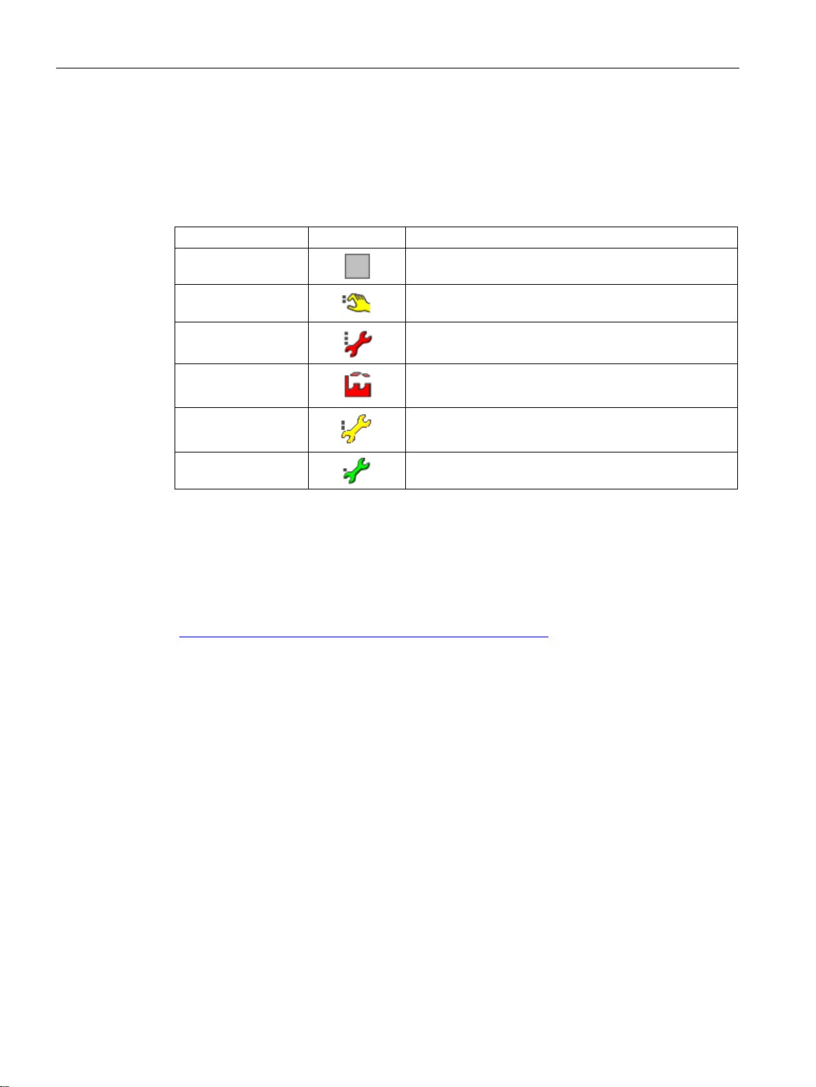
Description of the blocks
Icons
Quality Code
Symbol
Meaning
1
status.
Reference
4.1 Functions for all blocks
The icons for the Quality Code are displayed in the block icon and in the overview window of
the faceplates.
Table 4- 4 Icons for Quality Code display
16#80
16#60
16#00 1
16#28 1
16#68
16#A4
Active Quality Codes for the Trip, Intlock, Permit, and Protect parameters in the interlock
Good
Local function check / simulation
Bad, device-specific, value not valid
Bad, process-specific
Uncertain, device-specific
Maintenance demand
You can obtain further information on the Quality Code display, in the PCS 7 libraries APL
Styleguide programming manual in the Internet
(https://support.industry.siemens.com/cs/document/59062870
).
SIMOCODE pro PCS 7 Library V9.0
76 Programming and Operating Manual, 06/2017, A5E40899442002A/RS-AA/001
Page 77

Description of the blocks
4.1.5
Error numbers
Error
code
Error type
Description
MMDiag
MMMeas
MMStat
MMRevDhl
MMOprtn
cessed.
1
System error
Rack failure
X X X – X
2
System error
The module has been removed.
– – – – X
3
System error
The module does not respond.
X X X – X
4
System error
Subnet 1 or subnet 2 error
X – – – –
ule type
0 to 4.
LocalLi = 1
FwdForce = 1 and RevForce = 1
SimOn = 1
"X" = Error occurs in this block, "–" = Error does not occur in this block
Reference
4.1 Functions for all blocks
The SIMOCODE pro PCS 7 Library blocks have an output parameter ErrorNum that can be
used to output internal error states of the block as error numbers. Each error number is
assigned to a specific error. The routine always displays the error number of the error most
recently detected in a block cycle.
Table 4- 5 Error numbers per block
-1 – Predefined value when inserting
the block; the block is not pro-
0 – No error X X X X X
5 System error Module inserted, but invalid mod-
41 Program-
ming error
42 Program-
ming error
51 Program-
ming error
The value for LocalSetting I/O is
not within the permissible limits of
LocalSetting = 0 or
LocalSetting = 3 or
LocalSetting = 4 and
Error number for invalid signal
state
e.g. FwdLocal = 1 and StopLocal
= 1
FwdAut = 1 and StopAut = 1
AutModLi = 1 and ManModLi = 1
X X X X X
– – – – X
– – – X –
– – – X –
– – – X X
52 Program-
ming error
LocalAct = 1 and
LocalSetting = 2 or 4 and
IO station failure (PROFIBUS DP or PROFINET IO) (Page 98)
Fault handling (Page 110)
SIMOCODE pro PCS 7 Library V9.0
Programming and Operating Manual, 06/2017, A5E40899442002A/RS-AA/001
– – – X –
77
Page 78

Description of the blocks
4.1.6
Reading and writing data records
Read parameter data record
Write function
Errors when reading/writing data record
Error code
(W#16#...)
Description
ple, due to a lack of resources).
80A4
Bus communication disrupted
DPV1 service <> DS-Read/ DS-Write
80C0
The module has the data record, however there are no read data yet.
80C2
The module currently processes the maximum possible jobs for a CPU.
80C3
The required operating resources (memory, etc.) are currently occupied.
electrical interference.
80C6
Data record transfer was canceled due to priority class cancellation.
80C7
Job cancelled due to restart (warm restart) or cold restart of DP master.
4.1 Functions for all blocks
The blocks use SFB 52 "RDREC" function to read and process values from data records,
and the SFB 53 "WRREC" function to process and write values to data records of the
SIMOCODE pro device.
The "Read Data" button in the faceplates is used to update the displayed values by calling
the "RDREC" at the function block.
Reading can only be performed successfully if the function Write to data records "WRREC"
is not executed at the same time.
Reading data records is performed irrespective of the current mode.
It is only possible to write data records if the block is in REMOTE mode to configure current
limits for the SIMOCODE pro module configured with a current measuring module.
The following errors can occur when reading/writing the data record:
Table 4- 6 Errors when reading/writing data record
8085 Due to a problem in the system, information is not currently available (for exam-
80A2 DP protocol error at layer 2
80A3
80A9 Application – Feature/Function is not supported.
80C4 Internal temporary error. Job could not be carried out.
• PROFIBUS DP: DP protocol error with Direct-Data-Link-Mapper or user inter-
face/user
• PROFINET IO: General CM error
Repeat the job. If this error occurs often, check your installation for sources of
If any of these errors is detected, the function call to read or write data record is executed
again. The maximum count of these repetitive calls is set to 300 beyond which an error is
reported as a read error or write error at the
SIMOCODE pro PCS 7 Library V9.0
78 Programming and Operating Manual, 06/2017, A5E40899442002A/RS-AA/001
RdErr or WrErr output parameter respectively.
Page 79

Description of the blocks
4.1.7
Read Record error status
Displaying the error status in the "Alarm" view
4.1.8
Write Record error status
Displaying the error status in the "Alarm" view
4.1.9
Overview of the measuring point browser window
4.1 Functions for all blocks
The "Read Record" error status function is available for the MMDiag, MMOprtn, MMMeas,
MMStat and MMLog blocks.
The "Read Record" error status is shown at the output parameter RdErrStat.
To display the error status as a message in the "Alarm" view, proceed as follows:
1. Interconnect the output parameter
ExtVaXXX).
(
2. Interconnect the output parameter
ExtMsgX).
(
3. Configure the message in the auxiliary value ALARM_8P accordingly.
4. Compile and download the CFCs.
5. Recompile the OS.
The "Write Record" error status function is available for the MMOprtn and MMStat blocks.
The "Write Record" error status is shown at the output parameter WrErrStat.
To display the error status as a message in the "Alarm" view, proceed as follows:
1. Connect the output parameter
ExtVaXXX).
(
2. Connect the output parameter
ExtMsgX).
(
RdErrStat with one of the pins of the external values
RdErr with one of the pins of the external messages
WrErrStat with one of the pins of the external values
WrErr with one of the pins of the external messages
3. Configure the message in the auxiliary value ALARM_8P accordingly.
4. Compile and download the CFCs.
5. Recompile the OS.
SIMOCODE pro PCS 7 Library V9.0
Programming and Operating Manual, 06/2017, A5E40899442002A/RS-AA/001
For more information on measuring point browser, refer SIMATIC PCS 7 APL Function
Manual.
79
Page 80

Description of the blocks
4.1.10
Configurable response using the Feature I/O
4.1.10.1
Start-up characteristics
Set startup characteristics
Feature bit purpose
Note
The message classes Alarm, Warning and Tolerance are not valid for user
message classes. Take into consideration the validity of terms for user
classes.
Note
During 'Run
through messages with time stamps and auxiliary values beginning with
occur for
blocks with the startup characteristic
RunUpCycle
counter in the following cases:
•
•
This causes an outgoing message when initializing Alarm_
message after expiration of the RunUpCycle
4.1 Functions for all blocks
The alarm messages are suppressed in the OB100 for the RunUpCyc number of times. During
warm restart, the
When in the "Out of service mode", the block will continue to be in the same mode after a
warm restart.
Number of the Feature bit: 0
Set the startup characteristics of the function blocks, for example, for:
● MMRevDhl
● MMOprtn
The default setting is 0.
RdyToReset will be reset to zero.
-Stop-Run' transition of the CPU,the internally pending messages, non-stuck-
Feature bit = 0 and after the expiration of the
Alarm, warning or tolerance messages from the operating points (motor, valve, dosing,
controller and analog monitoring blocks)
Feedback errors (motor and valve blocks)
counter on the cyclic interrupt level.
SIMOCODE pro PCS 7 Library V9.0
80 Programming and Operating Manual, 06/2017, A5E40899442002A/RS-AA/001
-configured
-configured message
RunUpCycle
8P in OB100 and an incoming
Page 81

Description of the blocks
Set startup characteristics for motors
Bit = 0:
Bit = 1:
Note
Special note following complete download to the CPU
F
during the initial run as good (=1). When a motor protection signal is pending, this causes a
non
after the complete download and after expiration of the RunUpCycle
4.1.10.2
Response for Out of service mode
Feature bit purpose
Bit = 0:
Bit = 1:
4.1.10.3
Resets the commands for switching between modes
Feature bit purpose
Bit = 0:
4.1 Functions for all blocks
Starting the block in manual mode and in neutral position. With controllers, the
setpoint is set to (SP_Int) internally.
Starting the block with the last stored values, in other words in the last operating
mode set (manual, automatic or local mode) and at the last valid position.
ollowing a complete download to the CPU, the motor protection signal Trip is evaluated
-struck-through message with time stamp and auxiliary values beginning with RunUpCycle
Number of the Feature bit: 1
Define the reaction of the technologic block based on the interconnectable input parameter
OosLi = 1.
counter.
The default setting is 0.
The symbol for the "In progress" status appears in the block icon and in the faceplate
of the assigned technologic block. A 0-1 edge transition at the input parameter
further influence on the reaction of the technological block; the previous status is retained.
No switch to the "Out of service" mode is performed.
The mode switches to "Out of service" assuming that the block is "On" or "Manual"
mode. If this is not the case, the mode does not change. The symbol for the "In progress"
status also appears in the block icon and in the faceplate of the assigned technologic block
regardless of the mode change. If no message display on the faceplate then this indicates
whether the mode change has occured or not.
Number of the Feature bit: 2
Define how the block handles the incoming control commands AutModLi and ManModLi .
The default setting is 0.
commands for changing mode, the mode is not changed. In this case, the note text "Invalid
command" is displayed in the faceplate.
The control commands are not reset by the block. If there are two pending control
OosLi has no
SIMOCODE pro PCS 7 Library V9.0
Programming and Operating Manual, 06/2017, A5E40899442002A/RS-AA/001
81
Page 82

Description of the blocks
Bit = 1:
4.1.10.4
Enabling resetting of commands for the control settings
Feature bit purpose
Bit = 0:
Bit = 1:
4.1.10.5
Setting switch or button mode
Feature bit purpose
Bit = 0:
4.1 Functions for all blocks
control command is sent from the SFC, the command is reset automatically after a step is
exited.
The control commands are reset by the block. This, for example, ensures that if a
Number of the Feature bit: 3
With this Feature bit, you select how the block handles commands for the control settings
(for example motor on) via the interconnected input parameters.
The default setting is 0.
to the control settings at the same time, the status of the control settings is retained. In this
case, the "Invalid signal" message is displayed in the standard view of the faceplate.
control command is sent from the SFC, the command is reset automatically after a step is
exited.
The control commands are not reset by the block. If there are two commands relating
The control commands are reset by the block. This, for example, ensures that if a
Number of the Feature bit: 4
Determine whether a separate interconnectable 1-active control input has to be used for
every automatic command of the block or two automatic commands are assigned to a
control input (input signal as pulse signal or as static signal).
The Feature bit affects the following control inputs:
● starting and stopping a motor
● opening and closing a valve
● switching modes (parameters
Setpoint specification internal and external is given in the form of a pulse (pushbutton
operation) or a static signal (switching mode).
You can find the commands for controlling the block in the relevant section on block
operating modes. These are the parameters that are always used for the automatic
operation of a block.
latching reaction and is 1-active.
Button mode: Each automatic command is assigned to a control input. This has a
AutModLi and ManModLi)
SIMOCODE pro PCS 7 Library V9.0
82 Programming and Operating Manual, 06/2017, A5E40899442002A/RS-AA/001
Page 83

Description of the blocks
Example with a motor MMRevDhl:
Bit = 1:
Example with a motor MMRevDhl:
4.1.10.6
Set switching mode
Feature bit purpose
Bit = 0:
Bit = 1:
4.1.10.7
Enabling direct changeover between forward and reverse
Feature bit purpose
Bit = 0:
4.1 Functions for all blocks
In this case, use the interconnectable input parameters.
● FwdAut = 1 for the command "Start forward"
●
RevAut = 1 for the command "Start backwards"
●
StopAut = 1 for the stop command and
●
AutModLi = 1 for setting "Automatic" operating mode
●
ManModLi = 1 for setting "Manual" operating mode
Switching mode: two static automatic commands are assigned to a control input.
In this case, use the interconnectable input parameters.
● FwdAut = 1 for the command "Start forward"
●
RevAut = 1 for the command "Start backwards" and
●
FwdAut = 0 and RevAut = 0 for the stop command
●
AutModLi = 1 for setting "Automatic" operating mode
●
AutModLi = 0 for setting "Manual" operating mode
The
StopAut and ManModLi control inputs are irrelevant in this case.
Number of the Feature bit: 5
Specify switching mode for the motor block.
The default setting is 0.
Switching mode "On over speed 1" with the SwOverTi > 0 parameter
Switching mode "Off over speed 1" with the SwOverTi > 0 parameter.
Number of the Feature bit: 7
Enable direct reversal of the direction of motors.
The default setting is 0.
You can only change the direction of the motor by first stopping and starting the motor again
in the required direction. The motor can only be started again after the time set in the
IdleTime parameter has elapsed.
Direct reversal of the direction is disabled.
SIMOCODE pro PCS 7 Library V9.0
Programming and Operating Manual, 06/2017, A5E40899442002A/RS-AA/001
83
Page 84

Description of the blocks
Bit = 1:
4.1.10.8
Resetting via input signals in the event of interlocking (Protection) or errors
Feature bit purpose
Bit = 0:
Bit = 1:
4.1.10.9
Exit local mode
Feature bit purpose
Bit = 0:
Bit = 1:
4.1.10.10
Enable runtime for feedback signals
Feature bit purpose
Bit = 0:
4.1 Functions for all blocks
You can reverse the motor direction directly. The motor block reverses the direction
automatically. The motor is stopped and is started in the other direction when the time set in
the
Direct changeover is enabled.
IdleTime parameter has elapsed.
Number of the Feature bit: 9
Define how automatic control is to be re-enabled after an active interlock.
The default setting is 0.
only be restarted using a reset command. Reset is initiated either by operator input in the
faceplate or via the interconnectable input parameter (
currently pending command takes effect in automatic mode.
mode.
After an interlock (only Protection: Input parameter Protect) or errors, the system can
It is also possible to reset with a 0-1 edge change in the control signal in automatic
RstLi = 1) in the block. Thereafter, the
Number of the Feature bit: 10
Define how "Local mode" is either exited or will be exited with LocalSetting = 1 or
LocalSetting = 2 and if the mode is not specified by
The default setting is 0.
continuously adjusted).
prior to local mode (not bumpless).
Exiting local mode in manual mode (bumpless because the control signals are
When local mode is exited, the mode changes back to the last mode that was active
Number of the Feature bit: 11
To activate the runtime of feedback signals.
AutModLi or ManModLi.
The default setting is 0.
SIMOCODE pro PCS 7 Library V9.0
84 Programming and Operating Manual, 06/2017, A5E40899442002A/RS-AA/001
Deactivated: Tracking of feedback for simulation immediately after the trigger signal.
Page 85

Description of the blocks
Bit = 1:
4.1.10.11
Separate monitoring time for stopping the motor
Feature bit purpose
Bit = 0:
Bit = 1:
4.1.10.12
Enabling rapid stop via faceplate
Feature bit purpose
Bit = 0:
Bit = 1:
4.1.10.13
Activate bumpless changeover to automatic mode
Feature bit purpose
Bit = 0:
Bit = 1:
4.1 Functions for all blocks
of the monitoring time (
the monitoring time.
Activated: Tracking of feedback for simulation after the trigger signal and expiration
Number of the Feature bit: 13
To activate a separate monitoring time for stopping the motor.
The default setting is 0.
A monitoring time for starting and stopping the motor.
Separate monitoring time for stopping the motor.
Number of the Feature bit: 14
MonTiDynamic). The feedback signals are generated after expiration of
Specify if the OS operator can use rapid stop for the block via the standard view of the
faceplate.
The default setting is 0.
The "Rapid stop" button is not visible in the faceplate.
The OS operator can use the button for rapid stop.
Number of the Feature bit: 17
To enable the bumpless switchover from local/manual mode to automatic mode.
The default setting is 0.
automatic mode at any time.
switchover from local/manual mode to automatic mode is possible if the control settings of
the local/manual mode and automatic modes match. If switchover occurs at a different point
in any time, the "Switchover error" text is indicated on the faceplate.
Bumpless switchover is disabled. You can switch from local/manual mode to
Bumpless switchover from local/manual mode to automatic mode is enabled. A
SIMOCODE pro PCS 7 Library V9.0
Programming and Operating Manual, 06/2017, A5E40899442002A/RS-AA/001
85
Page 86

Description of the blocks
4.1.10.14
Activate fault status for external control system fault
Feature bit purpose
Bit = 0:
Bit = 1:
4.1.10.15
Reset even in locked state
Feature bit purpose
Bit = 0:
Bit = 1:
4.1.10.16
Disable Feedback Tracking LocalSetting 2 & 4
Feature bit purpose
Bit = 0:
Bit = 1:
4.1 Functions for all blocks
Number of the Feature bit: 18
Specify whether the block should switch to the error state at an external process control error
CSF =1.
The default setting is 0.
Block does not go to error state with process control error CSF = 1.
Activated: Block goes to error state with process control error CSF = 1.
Number of the Feature bit: 19
You can specify if it is possible to perform a reset with an active "Protection" or "Motor
protection" type interlock. This can be used, for example, to reset hardware interlocks.
The default setting is 0.
No reset is possible with a "Protection" type interlock or with active motor protection.
Reset is possible with a "Protection" type interlock or with active motor protection.
Number of the Feature bit: 20
To disable the tracking of feedback signals in the "Local" mode setting 2 and 4.
The default setting is 0.
Calculation of impulse controls in LocalSetting 2 and 4.
Disable calculation of impulse controls in LocalSetting 2 and 4.
SIMOCODE pro PCS 7 Library V9.0
86 Programming and Operating Manual, 06/2017, A5E40899442002A/RS-AA/001
Page 87

Description of the blocks
4.1.10.17
Bumpless switchover to automatic mode
Feature bit purpose
Bit = 0:
Bit = 1:
4.1.10.18
Update acknowledgement and error status of the alarm
Feature bit purpose
Bit = 0:
Bit = 1:
4.1.10.19
Activate local operator permission
Feature bit purpose
Bit = 0:
Bit = 1:
4.1 Functions for all blocks
Number of the Feature bit: 21
Specify whether bumpless switchover to automatic mode for valves, motors and dosing unit
can be enabled only if switching via the faceplate is in effect, or whether switching using
interconnectable inputs
The default setting is 0.
dosers" works when switching via the faceplate and switching using interconnectable inputs
AutModLi and ManModLi (ModLiOp = 1).
function only works for switching via the faceplate. Bumping switchover can be activated via
the inputs
The function "Bumpless switchover to automatic mode for valves, motors and
The "Bumpless switchover in automatic mode for valves, motors and dosers"
AutModLi and ManModLi (ModLiOp = 1).
Number of the Feature bit: 22
AutModLi and ManModLi (ModLiOp =1) is also possible.
To determine if the acknowledgement and error status of the message call at the block
output should be updated.
The default setting is 0.
updated. The block will run faster with this setting.
from the lower level message blocks. The lower level message blocks are called every other
cycle as long as an acknowledgement is expected or error information is pending.
The MsgErr, MsgStat and MsgAckn block outputs are set to the default settings and not
The MsgErr, MsgStat and MsgAckn block outputs are updated based on the feedback
Number of the Feature bit: 24
To enable local permission for a technologic block.
The default setting is 0.
Disabled
Enabled.
SIMOCODE pro PCS 7 Library V9.0
Programming and Operating Manual, 06/2017, A5E40899442002A/RS-AA/001
87
Page 88

Description of the blocks
4.1.10.20
Suppression of all messages
Feature bit purpose
Bit = 0:
Bit = 1:
4.1.10.21
Interlock display with LocalSetting 2 or 4
Feature bit purpose
Bit = 0:
Bit = 1:
Note
A decreasing motor protection (
regardless of the
This feature bit is also applicable for the LocalSetting 5 in VlvS where LocalSetting 4 is not
available.
4.1.10.22
Define reset as a function of the mode
Define reset as a function of the mode
Feature bit purpose
4.1 Functions for all blocks
Number of the Feature bit: 25
To determine whether all messages of the block are to be suppressed.
Messages are not suppressed.
Messages are suppressed.
Number of the Feature bit: 27
To specify the display of interlocks with LocalSetting 2 or 4 at the faceplate and at the
faceplate output
The default setting is 0.
not set with interlock.
LocalSetting 2 and 4 crossed out locks are displayed in the standard view. LockAct is
LockAct .
interlock.
LocalSetting 2 and 4 locks are displayed in the standard view according to the
LockAct is set according to interlock. This setting is used for hardware interlock.
Feature bit setting.
Number of the Feature Bit: 30
When the "Protection" interlock, feedback error ("Status error", "Control error") or "Motor
protection" signal is present again, this
Trip.Value=0) is displayed at the output parameter LockAct,
Feature bit is used to specify if a reset can be made
SIMOCODE pro PCS 7 Library V9.0
88 Programming and Operating Manual, 06/2017, A5E40899442002A/RS-AA/001
Page 89

Description of the blocks
Bit = 0:
Bit = 1:
Note
Rapid stop is unlocked for all operating modes using the "Reset" button in the faceplate
(RstOp = 1
RstLi = 1
Note
The local operating mode does not depend on this
mechanism.
Resetting the dosing mode depending on the operating mode (dosing blocks)
Bit = 0:
Bit = 1:
Note
The operating mode Local is independent of this feature bit. The dosing quantity can be
reset by the operator at the input RstDQ_Op
RstDQ_Li
4.1 Functions for all blocks
depending on the mode, only by the operator in manual mode or by the automatic I/Os in
automatic mode.
Resetting to manual mode is enabled with
Feature Bit 31 (Activating reset of protection /
error in manual mode). Also refer to the Resetting the block in case of interlocks or errors
chapter.
The default setting is 0.
Reset does not depend on the operating mode
In manual mode, manual reset by the operator is only possible if Feature Bit 31 is
set, otherwise no reset is required in manual mode.
In automatic mode, reset can only be made with automatic I/Os, regardless of Feature Bit 31.
This is performed either with a 0-1 edge transition at the
set, with a 0-1 edge transition at the automatic inputs, for example
RstLi input or, when Feature Bit 9 is
OpenAut, CloseAut.
); in CFC it is unlocked using the
input parameter.
Feature Bit and has a separate reset
This feature bit can also be used to set whether or not the reset of the dosing quantity is
dependent on the operating mode.
The default setting is 0.
RstDQ_Op. In automatic mode, a reset is only possible by a 0-1 edge transition at the input
RstDQ_Li.
Reset does not depend on the operating mode.
In manual mode, only a manual reset by the operator is possible at the input
or via a 0-1 edge transition at the input
.
SIMOCODE pro PCS 7 Library V9.0
Programming and Operating Manual, 06/2017, A5E40899442002A/RS-AA/001
89
Page 90

Description of the blocks
Set reset depending on the LiOp parameter (counter blocks)
Bit = 0:
Bit = 1:
4.1.10.23
Enable reset of interlocks in manual mode
Feature bit purpose
Bit = 0:
Bit = 1:
Note
Rapid sto
(RstOp = 1
RstLi
Note
The local operating mode has a separate reset mechanism.
4.1 Functions for all blocks
This feature bit can also be used to determine whether the setting or resetting to a default
value should be made dependent on the
The default setting is 0.
LiOp parameter.
LiOp = 0: Setting or resetting to a default value can only be made via the faceplate or at the
Setting or resetting to a default value does not depend on the LiOp parameter.
Setting or resetting to a default value depends on the LiOp parameter.
parameter for the faceplate.
LiOp = 1: Setting or resetting to a default value can only be made at the parameter for
interconnections.
Number of the Feature bit: 31
Specify whether a reset is necessary once the "Protection" interlock signal, feedback errors
("Runtime error", "Control deviation"), or "Motor protection" are present again. See also the
following section, 'Resetting the block in case of interlocks or errors' (Page 84).
The default setting is 0.
(
No reset required in manual mode.
Reset required in manual mode. The reset is performed using the "Reset" button
RstOp = 1) or, in CFC, using the input parameter RstLi.
p is unlocked for all operating modes using the "Reset" button in the faceplate
); in CFC it is unlocked using the
SIMOCODE pro PCS 7 Library V9.0
90 Programming and Operating Manual, 06/2017, A5E40899442002A/RS-AA/001
= 1 input parameter.
Page 91

Description of the blocks
4.1.10.24
Suppression of single alarm message
MMOprtn:
MMStat:
MMMeas:
Suppression of single alarm message
Feature bit purpose
Bit = 0:
Bit = 1:
Note
Alarm messages can be suppressed completely or separately using different feature bits
(Suppr
4.1.10.25
Resetting control in case of invalid command
Feature2 bit purpose
Bit = 0:
Bit = 1:
4.1.10.26
Setting switch or button mode for local commands
Feature2 bit purpose
4.1 Functions for all blocks
Feature Bit
To determine whether the alarm message described at the feature bit of the block is to be
suppressed.
Number of the Feature bit 0 to bit 14
Number of the Feature bit 10 to bit 17
Number of the Feature bit 10 to bit 17
Single alarm message is not suppressed.
Single alarm message is suppressed.
ession of all messages/ Suppression of single alarm message).
Number of the Feature2 bit: 3
To define the control priority in the event of an invalid input command.
The default setting is 0.
position".
In the event of an invalid input command, the control output is retained.
In the event of an invalid input command, the control output switches to the "neutral
Number of the Feature2 bit: 4
To determine whether a separate interconnectable 1-active control input has to be used for
every local command of the block or two local commands are assigned to a control input.
SIMOCODE pro PCS 7 Library V9.0
Programming and Operating Manual, 06/2017, A5E40899442002A/RS-AA/001
91
Page 92

Description of the blocks
Bit = 0
Example with a motor MotRevL:
Bit = 1
Example with a motor MotRevL:
Note
The StopLocal
4.1.10.27
Evaluation of the signal status of the interlock signals
Feature2 bit purpose
Bit = 0
Bit = 1
4.1 Functions for all blocks
The Feature2 bit affects the following control inputs for local mode in the form of a pulse
(pushbutton operation) or a static signal (switching mode):
● Starting and stopping a motor
● Opening and closing a valve
: Button mode: Each local command is assigned to a control input. This has a latching
reaction and is 1-active.
FwdLocal= 1 for the command "Start forward"
RevLocal= 1 for the command "Start backward"
StopLocal= 1 for the stop command
: Switching mode: Two static local commands are assigned to a control input.
FwdLocal= 1 for the command "Start forward"
RevLocal= 1 for the command "Start backwards"
FwdLocal = 0 and RevLocal = 0 for the stop command
In this case, use the interconnectable input parameters.
In this case, use the interconnectable input parameters.
control input is irrelevant in this case.
Number of the Feature2 bit: 5
You can use the Feature2.bit to specify if the signal status of the interlock inputs is to be
checked for the values 16#00 or 16#28.
The signal status of the inputs itself remains unchanged here.
The default setting is 0.
: The signal status is determined, an input with ST = 16#00 or 16#28 is forwarded with
value = 0.
: No evaluation of the signal status for 16#00 or 16#28.
SIMOCODE pro PCS 7 Library V9.0
92 Programming and Operating Manual, 06/2017, A5E40899442002A/RS-AA/001
Page 93

Description of the blocks
4.1.10.28
Forcing operating modes in the "Local" mode
Feature2 bit purpose
Bit = 0
Bit = 1
4.1.10.29
Considering bad quality of automatic commands or external values
Feature2 bit purpose
Bit = 0
Bit = 1
4.1.10.30
Separate interlock for each direction or position
Feature2 bit purpose
Bit = 0:
Bit = 1:
4.1 Functions for all blocks
Number of the Feature2 bit: 8
Specify whether forcing operating modes is possible in the "Local" mode.
The default setting is 0.
: In the "Local" mode, forcing operating modes is not possible.
: In the "Local" mode, forcing operating modes is possible.
Number of the Feature2 bit: 10
Use this bit to consider the bad signal status (16#00 or 16#28) in the parameter for the
automatic commands or external values to move the block into the neutral position.
The default setting is 0.
: The bad signal status will not be considered.
: The bad signal status (16#00 or 16#28) in the automatic commands or external values
will be considered from the block. The block goes to a defined neutral position.
Number of the Feature2 bit: 16
To enable the use of the "Separate interlock for each direction or position" function.
The default setting is 0.
One interlock for each direction or position.
Separate interlock for each direction or position.
SIMOCODE pro PCS 7 Library V9.0
Programming and Operating Manual, 06/2017, A5E40899442002A/RS-AA/001
93
Page 94

Description of the blocks
4.2
Diagnostics block MMDiag
4.2.1
Description of MMDiag
Purpose of the block
Views
References
4.2 Diagnostics block MMDiag
The MMDiag block is responsible for diagnosis of the SIMOCODE pro device.
● It evaluates the acyclic events:
– Start
– DP/IO station failure
– Module fault
– Process alarm
– Diagnosis alarm
● It generates the associated Quality Codes.
● It reads all diagnostic information for the MOD_SWT block.
● It transmits the status information to the signal processing block via the OMODE
parameter output.
The MMDiag block does not support views.
● Overview of the templates, control functions and blocks (Page 38)
● Functions for all blocks (Page 72)
● MMDiag block parameter (Page 234)
● Structure of UDTs for MMDiag (Page 237)
SIMOCODE pro PCS 7 Library V9.0
94 Programming and Operating Manual, 06/2017, A5E40899442002A/RS-AA/001
Page 95

Description of the blocks
4.2.2
Acyclic reading of data record 92
4.2.3
Message characteristics
Message block MsgEvId1
Message block
Message No.
Block parameters
Message text
Message
class *
MsgEvId1
1
Rack1Err
$$BlockComment$$ Subnet1: @1%d@: Fault
S
Rack2Err
RackF_Act
@1%d@/@5%d@/@3%d@: Failure
ModF_Act
@1%d@/@5%d@/@3%d@: Module error
BusFlt
@1%d@/@5%d@/@3%d@: Not reachable
6
ExtMsg1 **
$$BlockComment$$ External Message 1
S
7
ExtMsg2 **
$$BlockComment$$ External Message 2
S
8
ExtMsg3 **
$$BlockComment$$ External Message 3
S
* S = AS, OS process control fault
** User-definable message
4.2 Diagnostics block MMDiag
An interconnection is provided between output parameter RdDataOut of the block MMOrptn
and input parameter
RdData of the block MMDiag to enable the acyclic reading of DS92.
Data record 92 is read acyclically, i.e. it is only read when a
at MMOprtn or when either a trip or a warning is triggered by the device.
MMDiag signals the following errors/faults:
● DP/IO station fault (
● Rack fault (
● Module fault (
● Connection fault (
An error generates a group error
The
Subn1_Id and Subn2_Id parameters of the SUBNET function block (FB106) are linked
with the
the error information of the primary and redundant master system. This information is
provided to output parameters
ReadData operation is triggered
Rack1Err, Rack2Err)
RackF_Act)
ModF_Act)
BusFlt)
GrpErr in output parameter Err_Act.
Subn1Id and Subn2Id parameters of the MMDiag block. These parameters forward
Rack1Err and Rack2Err of the MMDiag block.
Table 4- 7 Output messages MMDiag
2
3
4
5
$$BlockComment$$ Subnet2: @2%d@: Fault S
$$BlockComment$$ Device
$$BlockComment$$ Device
$$BlockComment$$ Device
S
S
S
SIMOCODE pro PCS 7 Library V9.0
Programming and Operating Manual, 06/2017, A5E40899442002A/RS-AA/001
95
Page 96

Description of the blocks
Auxiliary values
Message No.
Auxiliary
value
Block parameters
Meaning
1
1
Subn1Id
ID of the primary subnet
Subn2Id
3
3
Rack_No
Rack number
4
4
Slot_No
Slot number
5
5
ExtVa105
Auxiliary value 5, user-definable
6
6
ExtVa106
Auxiliary value 6, user-definable
7
7
ExtVa107
Auxiliary value 7, user-definable
8
8
ExtVa108
Auxiliary value 8, user-definable
9
9
ExtVa109
Auxiliary value 9, user-definable
10
10
ExtVa110
Auxiliary value 10, user-definable
4.2.4
Driver generator
4.2 Diagnostics block MMDiag
Table 4- 8 Structure of the auxiliary values ALARM_8P
2 2
ID of the redundant subnet
The MsgStat1, MsgAckn1, and MsgErr1 parameters transfer the following information:
● Message status
● Message error
● Message acknowledgment status
The "Generate Module Driver" function automatically inserts the MMDiag block into the
following organization blocks within the run sequence:
● OB1 (cyclic program)
● OB40 (process alarm)
● OB82 (diagnostics alarm)
● OB83 (pull/plug alarm)
● OB85 (program execution error)
● OB86 (rack fault)
● OB100 (warm restart)
The block is inserted behind the OB_DIAG1 / OB_DIAG1_PN block in the CFC chart.
The
inputs are configured via the information from HW Config.
SIMOCODE pro PCS 7 Library V9.0
96 Programming and Operating Manual, 06/2017, A5E40899442002A/RS-AA/001
Rack_No, Slot_No, SubSlot_No, SubAddr, DAddr, LAddr, Subn1Id, Subn2Id and SubN_Typ
Page 97

Description of the blocks
4.2.5
Start-up characteristics
4.2.6
Module error
Note
The "module rack fault
4.2 Diagnostics block MMDiag
In OB100, the identifier for "Start up" is entered in output OMODE (OMODE = 16#xx01xxxx).
The alarm messages are suppressed in the OB100 for the
Acknowledge the errors
GrpErr, RackF_Act, ModF_Act, Rack1Err, and Rack2Err.
RunUpCyc no. of times.
Following a restart and when AccId = TRUE , a check of the module addressed with LAddr is
carried out. The system status list SSL ID xC91 is read out for this purpose. If the module
addressed with
fault" is entered for the
LAddr is missing, the ModF_Act output is set and the identifier for "higher-level
OMODE output (OMODE = 16#40xxxxxx).
The module fault is detected by the event number 16#61 for PROFIBUS and 16#51 for
PROFINET for event class 16#39.
The module fault is detected while the SIMOCODE pro device is configured behind a Y-Link.
The logical address of the module (
the module, e.g. from
SubN1_Id, Rack_No, Slot_No, SubSlot_No, and SubAddr.
LAddr) is derived based on the geographical address of
" takes precedence over the module fault.
SIMOCODE pro PCS 7 Library V9.0
Programming and Operating Manual, 06/2017, A5E40899442002A/RS-AA/001
97
Page 98

Description of the blocks
4.2.7
IO station failure (PROFIBUS DP or PROFINET IO)
Fault
Event number
Event class
PROFIBUS DP
RackF_Act
PROFIBUS DP station return
16#C4
16#38
PROFIBUS DP station error
16#C5
16#39
Reset PROFIBUS DP station error
16#C5
16#38
the module parameters
PROFINET IO
PROFINET IO system failure
16#CA
16#39
PROFINET IO station failure
16#CB
16#39
Reset PROFINET IO station error
16#C5
16#38
Return of PROFINET IO station, but error
16#CC
16#38
not equal to actual configuration
of the module parameters
Reference
4.2 Diagnostics block MMDiag
The OB_DIAG1 / OB_DIAG1_PN block detects the failure of the station, and evaluates it
based on the event class and event number (see table).
In the event of a fault, the identifier for "higher-level fault" (OMODE = 16#40xxxxxx) is
entered for the OMODE output.
PROFIBUS DP station failure (
PROFIBUS DP station return, but error in assignment of
Return of PROFINET IO station, but target configuration
Return of PROFINET IO station, but error in assignment
) 16#C4 16#39
16#C6, 16#C7 16#38
16#CD 16#38
16#CE 16#38
If the "rack failure" error (RackF_Act = 1) occurs, the connection to the device is lost (BusFlt
).
= 1
Error numbers (Page 77)
You will find more information about the organization blocks in the reference manual System
and Standard Functions for S7-300/400 in the Internet
(https://support.industry.siemens.com/cs/document/44240604
SIMOCODE pro PCS 7 Library V9.0
98 Programming and Operating Manual, 06/2017, A5E40899442002A/RS-AA/001
).
Page 99

Description of the blocks
4.2.8
Failure of a PROFIBUS DP station
Byte 0
Meaning
Reason or remedy
4.2.9
Malfunction when loading the OB
Fault
Event number
Event class
loaded to the CPU.
16#A3
16#B1, 16#B2
16#39
4.2 Diagnostics block MMDiag
The PROFIBUS connection error is reported at the BusFlt output of the MMDiag block and
as an alarm in WinCC.
Table 4- 9 Possible reasons for the connection error
Bit 0 1: DP slave cannot be
accessed by the DP
master.
• DP slave cannot be accessed by the DP master.
• Is the station address of the DP slave set correctly?
• Is the bus connection plug connected?
• Is voltage applied to the DP slave?
• Is the RS 485 Repeater secured correctly?
• Has a reset been performed on the DP slave?
Interrupt OB 85 sets or resets the priority class error GrpErr (malfunction when loading OBs).
Table 4- 10 Events during which OB 85 GrpErr is reset
Error when creating a start event for an OB. This is not
Error when the operating system accesses a module.
GrpErr is only triggered once for one execution cycle of the block.
16#A1, 16#A2 or
16#B3 16#39 or 16#38
16#35
SIMOCODE pro PCS 7 Library V9.0
Programming and Operating Manual, 06/2017, A5E40899442002A/RS-AA/001
99
Page 100

Description of the blocks
4.3
MMOprtn block
4.3.1
Description of MMOprtn
Purpose of the block
Block icons and faceplates
Views
Reference
4.3 MMOprtn block
The MMOprtn block supports the control functions in the Advanced Process Library (APL)
that are specific to SIMOCODE pro.
● Via the block, commands such as emergency start, test, trip reset are started because
these functions are not supported by the APL themselves.
● The block reads the data records.
● SIMOCODE data records are configured via the block.
The MMOprtn block faceplates can be displayed via the "Operation" button on the standard
view of the respectie APL block used in the template.
The block icon for the MMOprtn block can also be enabled at the CFC as described in
section 2.2
The status of the programmed control functions is displayed via the faceplates, e.g. motor
status, diagnostic information of the device.
The MMOprtn block supports the following views:
● Batch
● Trend
● Alarm
● Preview
● Standard (Page 148)
● Limits (Page 150)
● Diagnostics (Page 152)
● Process image (Page 153)
Block parameter MMOprtn (Page 244)
Functions for all blocks (Page 72)
Overview of the templates, control functions and blocks (Page 38)
SIMOCODE pro PCS 7 Library V9.0
100 Programming and Operating Manual, 06/2017, A5E40899442002A/RS-AA/001
 Loading...