

Page 1

s
Preface, Contents
SIMATIC
Vision Sensor SIMATIC
VS 130-2/VS 130-2vcr
Manual
Product Overview
System Integration
Installation
Commissioning
Operator Input
Process Interface
Diagnostics
Appendix
Index
1
2
3
4
5
6
7
8
Edition 09/2005
A5E00475759-01
Page 2

Safety Guidelines
This manual contains notices you have to observe in order to ensure your personal safety, as well as to
prevent damage to property. The notices referring to your personal safety are highlighted in the manual
by a safety alert symbol, notices referring to property damage only have no safety alert symbol. The
!
!
!
notices shown below are graded according to the degree of danger.
Danger
indicates that death or severe personal injury will result if proper precautions are not taken.
Warning
indicates that death or severe personal injury may result if proper precautions are not taken.
Caution
with a safety alert symbol indicates that minor personal injury can result if proper precautions are not
taken.
Caution
without a safety alert symbol indicates that property damage can result if proper precautions are not
taken.
Qualified Personnel
Prescribed Usage
Notice
indicates that an unintended result or situation can occur if the corresponding notice is not taken into
account.
If more than one degree of danger is present, the warning notice representing the highest degree of
danger will be used. A notice warning of injury to persons with a safety alert symbol may also include a
warning relating to property damage.
The device/system may only be set up and used in conjunction with this documentation. Commissioning
and operation of a device/system may only be performed by qualified personnel
the safety notices in this documentation qualified persons are defined as persons who are authorized to
commission, ground and label devices, systems and circuits in accordance with established safety
practices and standards.
Note the following:
Warning
!
This device and its components may only be used for the applications described in the catalog or the
technical description, and only in connection with devices or components from other manufacturers
which have been approved or recommended by Siemens.
Correct, reliable operation of the product requires proper transport, storage, positioning and assembly
as well as careful operation and maintenance.
. Within the context of
Trademarks
All names identified by ® are registered trademarks of the Siemens AG.
The remaining trademarks in this publication may be trademarks whose use by third parties for their
own purposes could violate the rights of the owner.
Disclaimer of Liability
We have reviewed the contents of this publication to ensure consistency with the hardware and
software described. Since variance cannot be precluded entirely, we cannot guarantee full consistency.
However, the information in this publication is reviewed regularly and any necessary corrections are
included in subsequent editions.
Siemens AG
Automation and Drives
Postfach 4848
90437 NÜRNBERG
GERMANY
Copyright © Siemens AG 2005
A5E00475759-01
Siemens AG 2005
Technical data subject to change.
Page 3

Preface
Purpose of the Manual
This manual describes the vision sensors SIMATIC VS 130-2 and
VS 130-2vcr. It helps to install, commission and operate the sensors.
The documentation addresses personnel concerned with the engineering,
commissioning and service of automation systems and visualization equipment.
Guide
The manual contains the following guides which provide quick access to the
specific information you need:
• The manual opens with a complete directory.
• The manual closes with a detailed index for quick access to the information
you require.
Further information
An installation and wiring manual is included in paper form.
On your CD you will find the "Getting Started" guide for initial commissioning of
your SIMATIC VS 130-2 or VS 130-2vcr vision sensor.
Further support
If you have any questions concerning the use of products which are not answered
in this manual, please contact your local Siemens partner at your Siemens office.
You can find your local partner at:
http://www.siemens.com/automation/partner
You can find a guide to the technical documentation on offer for the individual
SIMATIC products and systems at:
http://www.siemens.de/simatic-tech-doku-portal
You can find the catalog and online ordering systems at:
http://mall.automation.siemens.com/
Vision Sensor SIMATIC VS 130-2/VS 130-2vcr
A5E00475759-01
iii
Page 4

Preface
Training center
To help you to learn about the vision sensors SIMATIC VS 130-2 and
VS 130-2vcr and the S7 automation system, we provide a range of training
courses. Please contact your regional training center or the central training center
in Nuremberg, Germany.
Telephone: +49 (911) 895-3200.
Internet: http://www.sitrain.com
Technical support
How to reach technical support for all A&D products
• With the Support Request form on the Web:
http://www.siemens.de/automation/support-request
• Telephone: + 49 180 5050 222
• Fax: + 49 180 5050 223
Further information about our technical support is available in the Internet at
http://www.siemens.com/automation/service
Service & Support on the Internet
The Siemens Service & Support team provides you with comprehensive additional
information on SIMATIC products in its online Internet services.
http://www.siemens.com/automation/service&support
There you can find:
• Current product information and downloads which you may find useful for your
product.
• The documents you require, using our Service & Support search engine.
• A forum where users and experts from all over the world exchange ideas
• Your local partner for Automation & Drives.
• Information about onsite services, repairs, spare parts. Lots more is available
to you on our "Service“ pages.
Vision Sensor SIMATIC VS 130-2/VS 130-2vcr
iv A5E00475759-01
Page 5

Contents
1 Product Overview 1-1
1.1 Product Description .......................................................................................... 1-1
1.2 Components ..................................................................................................... 1-4
1.3 Processing Configuration.................................................................................. 1-5
1.4 Important Requirements for Installation............................................................ 1-6
1.5 Applications ...................................................................................................... 1-6
1.6 The lamp multiplexer accessory ....................................................................... 1-9
1.7 Requirements for Codes and Legibility........................................................... 1-11
1.7.1 What is Required of Data Matrix and Vericodes? .......................................... 1-11
1.7.2 Requirements for QR codes ........................................................................... 1-15
1.7.3 Requirements for PDF417 codes ................................................................... 1-17
2 System Integration 2-1
2.1 Design............................................................................................................... 2-1
2.2 Application Examples ....................................................................................... 2-2
2.2.1 Reading codes or checking quality in stand-alone mode
with output over Ethernet.................................................................................. 2-2
2.2.2 Reading Codes or Quality in Stand-alone Mode with Output over RS-232 ..... 2-3
2.2.3 Reading Codes or Quality in a PROFIBUS Environment.................................2-4
2.2.4 Reading Codes or Quality in a PROFINET Environment ................................. 2-5
2.2.5 Reading codes or checking quality in a PROFINET environment
and outputting over Ethernet ............................................................................ 2-6
2.2.6 Mixed operation ................................................................................................ 2-6
3 Installation 3-1
3.1 Installing Components for VS 130-2................................................................. 3-1
3.2 Wiring Components .......................................................................................... 3-3
3.3 Guidelines on Interference-Proof Installation ................................................... 3-5
3.4 Guidelines for Installing PROFIBUS DP or PROFINET I/O ............................. 3-5
4 Commissioning 4-1
4.1 Introduction ....................................................................................................... 4-1
4.2 Turning on the Device....................................................................................... 4-1
4.3 Control and Display Panel ................................................................................ 4-3
4.4 Adjusting the Sensor with the Setup Support................................................... 4-5
Vision Sensor SIMATIC VS 130-2/VS 130-2vcr
A5E00475759-01
v
Page 6

Contents
5 Operator Input 5-1
5.1 Overview........................................................................................................... 5-1
5.2 Working with the Processing Unit..................................................................... 5-1
5.3 Working with the Setup Support ..................................................................... 5-26
5.3.1 Starting Setup Support in the Web Browser................................................... 5-28
5.3.2 User interface of the VS 130-2/VS 130-2vcr ..................................................5-29
5.3.3 Adjust Sensor .................................................................................................5-31
5.3.4 Connections.................................................................................................... 5-34
5.3.5 Train................................................................................................................ 5-37
5.3.6 Evaluating ....................................................................................................... 5-39
5.3.7 Options............................................................................................................ 5-40
5.3.8 Info .................................................................................................................. 5-44
5.3.9 Maintain ..........................................................................................................5-48
5.3.10 Stop.................................................................................................................5-48
5.4 Operator Control over Personal Digital Assistant (PDA)................................ 5-49
5.4.1 Prerequisites................................................................................................... 5-49
5.4.2 Establishing a Connection between PDA and Processing Unit......................5-49
5.4.3 Starting or stopping setup support from the PDA........................................... 5-50
5.4.4 User interface of the PDA............................................................................... 5-50
5.4.5 Known PDA problems..................................................................................... 5-54
6 Process Interface 6-1
6.1 Introduction ....................................................................................................... 6-1
6.2 Integrating the DP slave VS 130-2 in HW Config............................................. 6-2
6.3 Integrating the PROFINET I/O Device VS 130-2 in HW Config ....................... 6-4
6.4 Control Via the "DI/DO" I/O Interface ............................................................... 6-6
6.4.1 Control Signals .................................................................................................6-6
6.4.2 Selecting the Mode ........................................................................................... 6-7
6.5 Control over PROFIBUS DP and PROFINET IO ........................................... 6-11
6.5.1 File Transfer Principle over PROFIBUS DP and PROFINET IO.................... 6-11
6.5.2 Assignments for PROFIBUS DP and PROFINET IO-relevant Interfaces
for the Processing Unit ...................................................................................6-12
6.5.3 Sample program for data exchange if code length <= 27 bytes..................... 6-15
6.5.4 Programming the Data Block.......................................................................... 6-17
6.5.5 FB 79 "VS130-2_CONTROL"......................................................................... 6-19
6.6 Sample Programs ........................................................................................... 6-32
6.6.1 Sample Program for Interfacing the VS 130-2 to a SIMATIC Controller
with the Aid of FB79........................................................................................ 6-32
6.6.2 Sample Program for Outputting the Read Code to a PC or PG..................... 6-33
6.6.3 Sample Program for Archiving Diagnostic Information on a PC or a PG ....... 6-34
7 Diagnostics 7-1
7.1 Introduction ....................................................................................................... 7-1
7.2 Diagnostics with Messages .............................................................................. 7-1
7.2.1 Error Messages ................................................................................................7-2
7.2.2 Warnings/Notes ................................................................................................ 7-7
7.2.3 Read Results .................................................................................................. 7-10
7.3 Diagnostics Based on the "BF" LED............................................................... 7-11
7.3.1 "BF" LED with PROFIBUS DP........................................................................ 7-11
7.3.2 "BF" LED with PROFINET IO ......................................................................... 7-11
7.4 Slave Diagnostics or I/O Device Diagnostics .................................................7-12
7.4.1 Introduction ..................................................................................................... 7-12
7.4.2 Reading Out the Diagnostic Information with S7............................................ 7-12
7.4.3 Diagnostics for PROFIBUS DP ......................................................................7-13
7.4.4 Diagnostics for PROFINET IO........................................................................ 7-15
Vision Sensor SIMATIC VS 130-2/VS 130-2vcr
vi A5E00475759-01
Page 7

Contents
8
Appendix 8-1
8.1 Components of the Product .............................................................................. 8-1
8.2 Standards and Approvals .................................................................................8-6
8.3 Installation Dimensions..................................................................................... 8-7
8.4 Interface Assignment of the Processing Unit.................................................... 8-9
8.5 Calculating the C-mount Lens and the Size of the Field of View
for Data Matrix Codes at a Given Distance .................................................... 8-12
8.6 Technical Specifications ................................................................................. 8-15
8.6.1 Vision Sensor SIMATIC® VS 130-2/VS 130-2vcr .......................................... 8-15
8.6.2 General Specifications....................................................................................8-18
8.6.3 Interface Digital Inputs/Outputs ...................................................................... 8-21
Index Index-1
Vision Sensor SIMATIC VS 130-2/VS 130-2vcr
A5E00475759-01
vii
Page 8

Contents
Vision Sensor SIMATIC VS 130-2/VS 130-2vcr
viii A5E00475759-01
Page 9

1 Product Overview
1.1 Product Description
The Vision Sensor SIMATIC VS 130-2 is a code reader for data matrix codes of the
type ECC200 (with the exception of the types "Structured Append" and
"Reader Programming Code") and the codes PDF417 and QR (with the exception
of the types "ECI Code", "Byte Code", "Kanji Code", "Structured Append" and
"FNC1 Code"). The code type is detected during training and adjustment and
during training is saved as a code property.
The Vision Sensor VS 130-2vcr is Vericode reader.
You can use these readers to read the coded labeling of products and then pass
the read code to a PLC or a computer.
The SIMATIC VS 130-2/VS 130-2vcr operates with overhead lighting. The object is
lit from above with the supplied ring flash. With the lamp multiplexer accessory, it is
possible to select one of up to 4 lamps for the lighting.
The Vision Sensor SIMATIC VS 130-2/VS 130-2vcr is available in the following
models:
• SIMATIC VS130-2 for large code areas
(order number of the full package: 6GF1 130-1BA with 2.5 m cable length and
6GF1 130-1BA01 with 10 m cable length)
• SIMATIC VS130-2 for small code areas
(order number of the full package: 6GF1 130-2BA with 2.5 m cable length and
6GF1 130-2BA01 with 10 m cable length)
• SIMATIC VS130-2 for very small code areas
(order number of the full package: 6GF1 130-4BA with 2.5 m cable length and
6GF1 130-4BA01 with 10 m cable length)
• SIMATIC VS130-2 for variable code areas (order number of the basic package:
6GF1 130-3BC with 2.5 m cable length and 6GF1 130-3BC01 with 10 m cable
length) if you use the C- or CS-mount lenses (includes the high-resolution
sensor)
• SIMATIC VS130-2 for variable code areas
(order number of the basic package: 6GF1 130-3BB with 2.5 m cable length
and 6GF1 130-3BB01 at 10 m cable length), if you are using C or CS-mount
lenses and want to use the lens protective housing (6GF9 002-7AA01).
• SIMATIC VS 130-2vcr (Vericode reader) for variable code areas (order number
of the basic package: 6GF1 130-3BB02)
Vision Sensor SIMATIC VS 130-2/VS 130-2vcr
A5E00475759-01
1-1
Page 10

Product Overview
Reading, matching or verifying code
SIMATIC VS 130-2/VS 130-2vcr can read codes, match the entire code or part of it
with a trained code and relate (verify) the quality values of the currently read code
to the quality values of a trained code.
The entire read character string or only part of it (in other words, filtered) can be
output. When it is output, further characters can de appended at the start or end as
a prefix or suffix.
The SIMATIC VS 130-2/VS 130-2vcr can operate both in standalone mode to
make good/bad decisions or as part of a control system to pass on the read codes
for further processing.
Performance Features
• Reliable reading of data matrix codes or Vericodes even under difficult
conditions (for example, for oil-smeared or needle-punched codes)
• Reading printed or lasered codes of the type PDF417 and QR on a
homogeneous background
• Overhead ring flash with VS 130-2
• Activation of up to 4 lamps using a special lamp multiplexer
• Linking of several trained codes that do not necessarily belong to the same
code type to form a code set with the VS 130-2
• It is possible to specify a region of interest with the VS 130-2
• Fully Web-based user interface
• When using data matrix codes, up to 20 codes can be read per second
• With Vericodes up to 5 code readings per second
• Calculating quality characteristics
• Extensive operator control and monitoring functions even in the processing
mode
• Wide-ranging diagnostics and logging functions: Error image memory and
event logging
• Firmware update over the user interface
• Control over digital I/O, trigger signal and also over RS-232 interface of an
RS-232 Ethernet converter or TCP server
• Acquiring the code without a trigger signal ("Continuous" mode)
• Event output over PROFIBUS DP, PROFINET I/O, RS-232 interface of an
RS-232 Ethernet converter, and TCP connection to PC
You will find the Technical Specifications of SIMATIC VS 130-2/VS 130-2vcr in the
appendix.
Vision Sensor SIMATIC VS 130-2/VS 130-2vcr
1-2 A5E00475759-01
Page 11

Product Overview
Code Properties
To improve clarity, the following terms are used in the table below:
• Variant 1: SIMATIC VS 130-2 for "large code areas" (6GF1 130-1BA and
6GF1 130-1BA01 with sensor head 6GF2 002-8DA01)
• Variant 2: SIMATIC VS 130-2 for "small code areas" (6GF1 130-2BA and
6GF1 130-2BA01 with sensor head 6GF2 002-8EA01)
• Variant 3: SIMATIC VS 130-2 for "very small code areas" (6GF1 130-4BA and
6GF1 130-4BA01 with sensor head 6GF2 002-8FA01)
• Variant 4: C/CS Mount (6GF1 130-3BB and 6GF1 130-3BB01 with sensor
head 6GF2 002-8CB)
• Variant 5: C/CS Mount (6GF1 130-3BC and 6GF1 130-3BC01 with sensor
head 6GF2 002-8GB)
• Variant 6: C/CS Mount (6GF1 130-3BB02 with sensor head 6GF2 002-8CB) for
acquiring Vericodes
Properties Configuration 1 Configuration 2 Configuration 3 Configuration 4
and
Configuration 6
CCD resolution 0,11 mm/pixel 0,06 mm/pixel 0.032 mm/pixel Image width /
640 pixels
Minimum dot size
(edge length)
Maximum dot
size (edge
length)
Minimum code
dimension
(rows * columns)
Maximum code
dimension
(rows * columns)
Clearance
sensor front edge
- test object
Image field 75 mm * 57 mm 45 mm * 34 mm 20 mm * 15 mm depending on
1)
With large code dimensions such as 72*72, make sure that the lens used does not cause any distortion
at the edges.
0,6 mm 0,35 mm 0,16 mm Image width /
120 pixels
3,5 mm 2 mm 1 mm Image width /
22 pixels
10 *10 10 *10 10 *10 10 *10 10 *10
48 *48 48 *48 48 *48
100 mm 90 mm 75 mm Depending on
72 *72
lens
lens
1)
72 *72 1)
Configuration 5
Image width /
1024 pixels
Image width /
200 pixels
Image width /
35 pixels
Depending on
lens
depending on
lens
Vision Sensor SIMATIC VS 130-2/VS 130-2vcr
A5E00475759-01
1-3
Page 12

Product Overview
1.2 Components
The complete Vision Sensor SIMATIC VS 130-2/VS 130-2vcr consists of the
following:
• Sensor head with CCD sensor chip (CCD = Charge Coupled Device) for
sensing the code
• LED overhead lighting unit, red, degree of protection IP65 as ring flash
(order number 6GF9 004-8BA01; only with VS 130-2)
• Processing unit for code processing, output of results, PROFIBUS DP and
PROFINET I/O communication and parameter assignment
• Cables to connect the individual components
• Installation instructions for installing and wiring the
SIMATIC VS 130-2/VS 130-2vcr
• CD with:
- This manual SIMATIC VS 130-2/VS 130-2vcr (German, English, French,
Spanish, Italian for VS 130-2, German and English for VS 130-2vcr)
- Online help (interfacing the Com Server of W&T, establishing the
connection, setup support)
- Getting Started
- Installation Instructions
- Compact Com Server manual from W&T
- The installation manual SIMATIC S7-300 Automation System, Hardware
and Installation
- Getting Started Collection for PROFINET I/O
- PROFINET System Manual, System Description
- PROFINET IO from PROFIBUS DP to PROFINET IO Programming
Manual
- PROFINET IO Structure of the Diagnostic Data Records Product
Information
- The device master data file SIEM8111.GSD and the corresponding bitmap
file VS1X0__N.DIB (for PROFIBUS DP)
- the GSD file GSDML-V1.0-Siemens-VS130-2-20041021.xml (General
Station Description) and the bitmap file vs100.bmp (for PROFINET I/O)
- Three sample programs (connecting the VS 130-2 to a SIMATIC controller
using FB79, output of the read code to a PC or a PG, archiving diagnostic
information on a PC or PG)
Overview of the complete package
Vision Sensor SIMATIC VS 130-2/VS 130-2vcr
1-4 A5E00475759-01
Note
If you want to use C or CS-mount sensors under IP65 conditions, use the lens
protective housing (6GF9 002-7AA01).
Page 13
Product Overview
1.3 Processing Configuration
Triggering
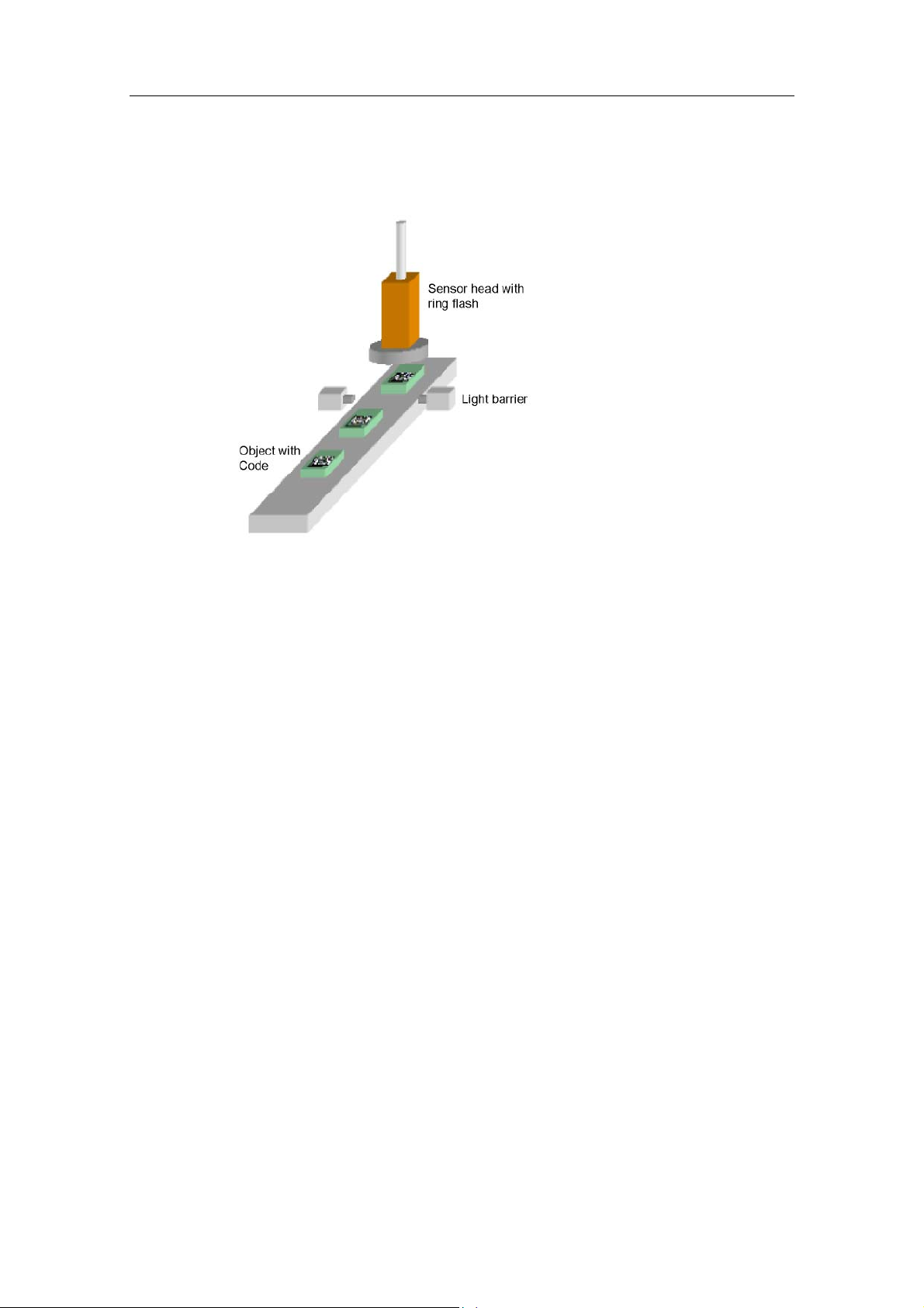
The objects with the code are fed past the sensor head with a suitable conveyor.
They must be located fully within the sensor field of view when being read.
In the training mode, the character content of the code is saved.
In the processing mode, the current code is read and, if required, compared with
the saved content of the trained code. The digital output signals are set according
to the read result: READ (code was localized and decoded), MATCH (code
matches the trained code), N_OK (code was not legible).
The read result is output over PROFIBUS DP, PROFINET IO or over the RS-232
interface of an RS-232 Ethernet interface converter or over a TCP server
depending on the parameter settings.
To read the code, you must make sure that the code is completely within in the
sensor field of view and clearly visible.
The code is captured at the trigger time. In this case, you generate an exact and
debounced trigger signal at the trigger time, for example with a laser light barrier.
As an alternative, you can record the code without a trigger signal (trigger source
"endless"). In this case the code is output again only when there is a code change.
This is required, for example, with rotating parts if the exact position of the code is
not known.
You can check your settings with the setup support of the VS 130-2/VS 130-2vcr.
Vision Sensor SIMATIC VS 130-2/VS 130-2vcr
A5E00475759-01
1-5
Page 14
Product Overview
1.4 Important Requirements for Installation
The following requirements must be met:
• The code must be clearly visible:
- There should be as few reflections as possible in the code field.
- The code field should be uniformly illuminated without shadows.
- All parts of the code should be sharply printed.
• The sensor can be up to 40° from the vertical.
• The distance between the code and the image edge should be at least two dot
widths.
1.5 Applications
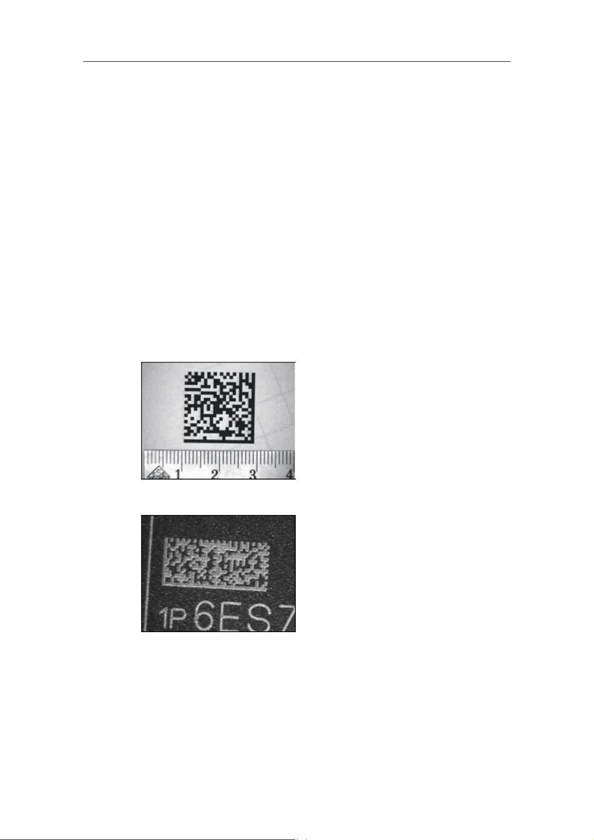
Below, you will see several examples of data matrix codes, QR, PDF417 and
Vericodes:
• Printed data matrix code
• Lasered data matrix code (plastic surface)
Vision Sensor SIMATIC VS 130-2/VS 130-2vcr
1-6 A5E00475759-01
Page 15
Product Overview
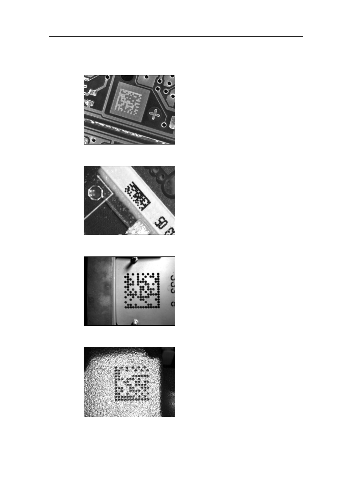
• Lasered data matrix code (pcb)
• Data matrix code created with inkjet printer
• Punched data matrix code
• Needle punched data matrix code
Vision Sensor SIMATIC VS 130-2/VS 130-2vcr
A5E00475759-01
1-7
Page 16
Product Overview
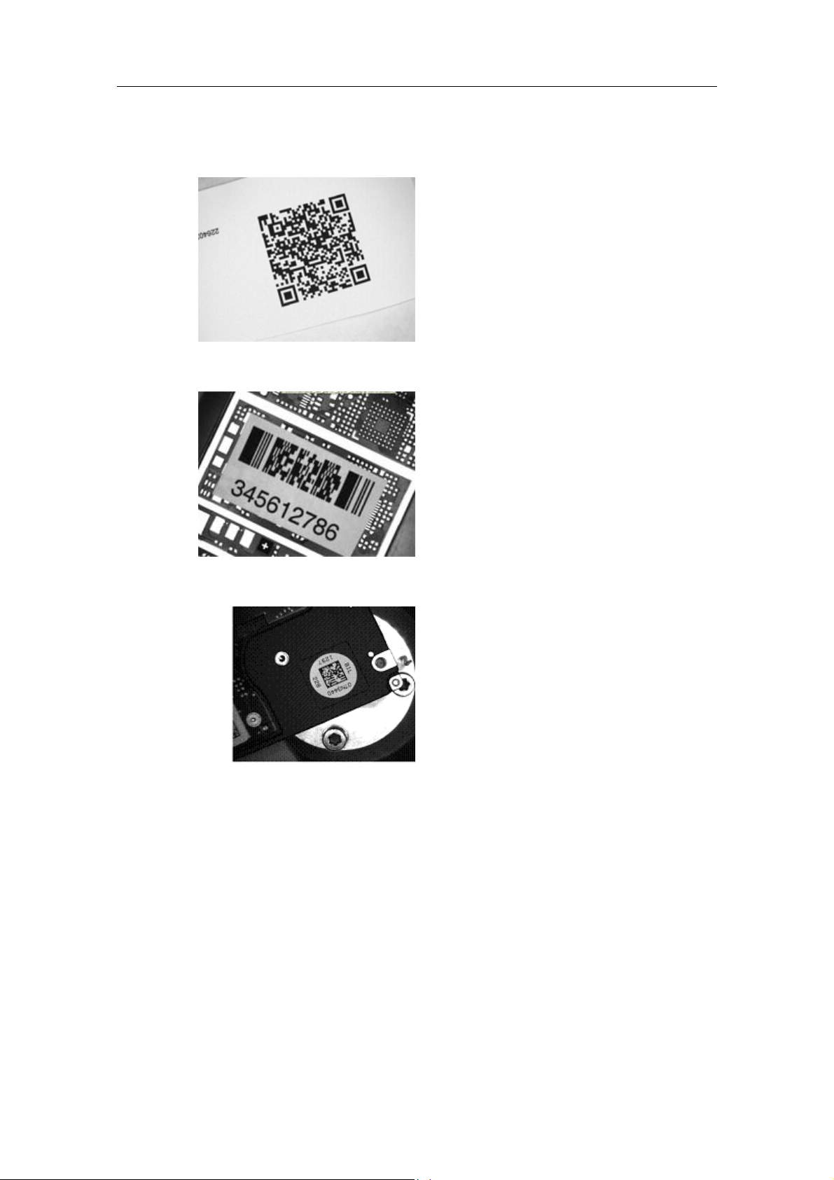
• Printed QR code
• Printed PDF417 code
• Vericode
Vision Sensor SIMATIC VS 130-2/VS 130-2vcr
1-8 A5E00475759-01
Page 17
Product Overview
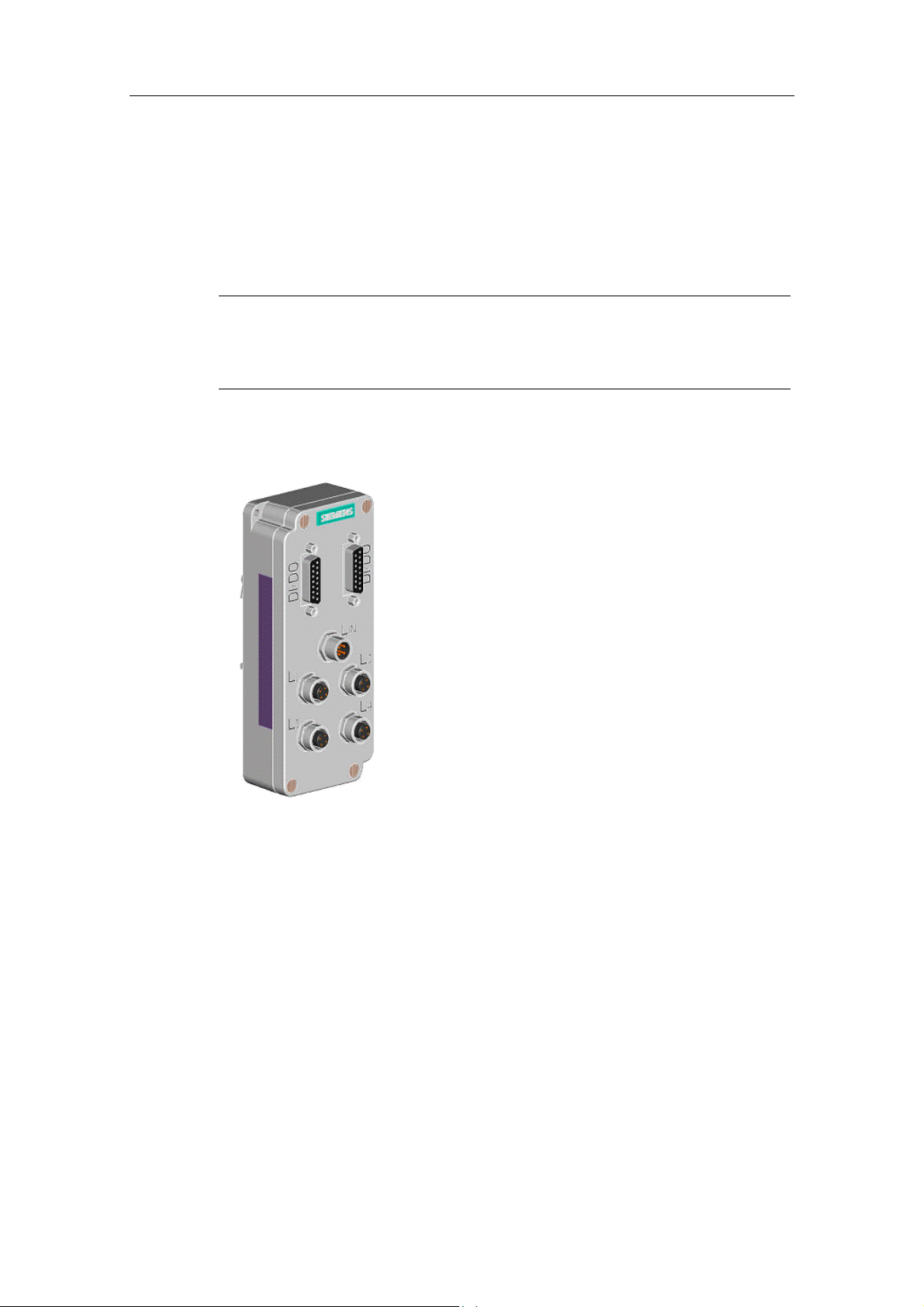
1.6 The lamp multiplexer accessory
If there are varying lighting conditions in the vicinity of the sensor head, it is
sometimes advisable to work with different lamps at different times. You can
therefore connect up to 4 flash lamps to the Vision Sensor VS 130-2/VS 130-2vcr
using he lamp multiplexer (6GF9 002-7BA).
Note
The lamp multiplexer can only be used if you have set the multilight mode. If you
not activate the multilight mode, you must connect your lamp directly to the
processing unit.
The lamp multiplexer is shown in the figure below.
Vision Sensor SIMATIC VS 130-2/VS 130-2vcr
A5E00475759-01
1-9
Page 18

Product Overview
Connecting the lamp multiplexer
You connect to the processing unit as follows: Connect a lighting cable
(6GF9 002-8CE) to the LAMP socket of the processing unit and to the input socket
LIN. of the lamp multiplexer.
Connect each of the maximum four lamps to the lamp multiplexer over a lighting
cable. Lamp 1 is assigned to socket L1, lamp 2 to socket L2 etc.
Connect the socket connector "DI/DO" of the processing unit to the left-hand plug
connector "DI/DO" of the lamp multiplexer with the supplied special cable. You can
connect a digital communication cable (6GF9 002-8CB) to the right-hand plug
connector "DI/DO". Please remember that you must not then use the MATCH and
NOK signals. These are used to select a lamp.
Note
If you connect the lamp multiplexer with connected lamps to a
VS 130-2/VS 130-2vcr while this is operating, this can lead to the processing unit
resetting itself in some situations.
Installing the lamp multiplexer
You have the following installation options:
• Wall-mounting using the two holes at the upper end of the lamp multiplexer
• Installation on a standard rail: In this case, screw the supplied rail adapter to
the back of the lamp multiplexer.
Vision Sensor SIMATIC VS 130-2/VS 130-2vcr
1-10 A5E00475759-01
Page 19

Product Overview
1.7 Requirements for Codes and Legibility
1.7.1 What is Required of Data Matrix and Vericodes?
General Requirements for Data Matrix and Vericodes to Ensure Readability
VS 130-2 can read data matrix codes with properties corresponding to those
published in the standard for data matrix codes. In many ways, VS 130-2 reacts
tolerantly even when certain basic properties are absent and is capable of dealing
with difficulties that are not specified in the standard.
As a result, VS 130-2 and VS 130-2vcr have a very wide range of application in
normal situations, a fact reflected in the following broad limits:
• It can read codes in which directly adjacent code points have a minimum
distance of only 5 pixels and up to a maximum distance of 35 pixels.
• The deviation of the sensor axis from the vertical can be between 0 ° und 40 °.
• The code field can approach the edge of the image up to a distance equivalent
to twice the code point diameter.
• The dominant polarity of the code points compared with the background is
required uniformly for all points (as it was during the training procedure). Slight
shadows or shiny areas are tolerated.
• The ratio of the distance to the closest neighbor and the diameter of any code
point can be between 2 and 0.8.
• Although code points must be printed according to a regular square grid
pattern, individual points can be displaced from their ideal position by up to 1/3
of the grid unit. Even slight parallelogram-shaped distortion is tolerated.
• With large-image but small-dimensioned codes, slight curves in the printed
material surface are tolerated. With high-value codes (for example, more than
14 x 14) or a strongly inclined sensor axis, curves are not allowed.
• Large tolerance of background disturbances that cannot be described
quantitatively
• Large tolerance of poor contrast conditions
• Due to the limited image resolution, codes with a maximum code dimension of
72x72 can be read.
In terms of these limit characteristics and when using minimum read rates due to
the requirements of the application (can be set with the "Cycletimelimit" parameter)
the tolerances are generally restricted, in some cases in stages, or other conditions
come into play. The limits described below are intended mainly as guidelines since
the actual conditions in a real application cannot be assessed accurately in
advance. It is therefore conceivable that higher read rates can be achieved even if
individual conditions are not fully adhered to.
Vision Sensor SIMATIC VS 130-2/VS 130-2vcr
A5E00475759-01
1-11
Page 20

Product Overview
Processing Method for Reliable Reading of Difficult Data Matrix Codes and
Vericodes
Settings:
• Speed = low
• Exposure = Manual or Auto V1 or Auto
The self-adapting recognition method of VS 130-2/VS 130-2vcr allows the most
difficult codes to be read reliably. The most reliable detection is reached by
VS 130-2/VS 130-2vcr when you make adequate time available for adaption by
setting a high cycle time limit.
The recognition method is designed for a variety of practical situations in which
various aspects of the read configuration cannot be considered ideal. For example:
• Any alignment and position of the code in the image
• Reading codes even when dots overlap or are largely isolated
• Reading codes recorded mirror-inverted
• Tolerance of distortion, due for example to inclined installation of the image
sensor (view angle down to a lower limit of approximately 50° to the printed
surface)
• Resistant to similar-looking foreign objects in the area of the code
• Resistant to interference patterns (grooves, granularity) in the area of the code
• Good tolerance of contrast fluctuations
• Good range of imaging size from 5 to 35 pixels per dot
Rectangular or square codes (with data matrix codes with maximum dimensions of
72 x 72 dots) can be read, whereby the brightness polarity (bright on dark or dark
on bright) is unimportant.
If individual conditions are particularly favorable and stable in a concrete situation
(and therefore less effort is required for internal adaption), the read rate of
VS 130-2/VS 130-2vcr can reach a peak of 20 per second. You can influence this
by setting the "Speed" and "Cycle time limit" parameters as described below.
Vision Sensor SIMATIC VS 130-2/VS 130-2vcr
1-12 A5E00475759-01
Page 21
Product Overview
Processing Method for Fast Reading of Data Matrix Codes and Vericodes with a
Guaranteed Read Rate up to 5Hz
Settings:
• Speed = medium
• Exposure:
- = Manual: guaranteed read rate of 5 Hz
- = Auto V1 and Auto: guaranteed read rate of 3.3 Hz
These read rates are achieved under the following conditions:
• The code dimension must not be greater than 40 x 40 dots.
• The code must be positioned so that there is always a clearance of at least 3
dots to the edge of the image.
• The code should not make contact with any other objects in the image (keep
the quiet zone free!)
• To allow the code to be found quickly, there must be no other objects (bus
structures count here as well) in the image with enclosed rectangle and of a
comparable size to the trained code. (See also the two following figures.)
• The minimum dot size is 5 pixels per dot without restrictions.
• The view angle must be greater than 70°.
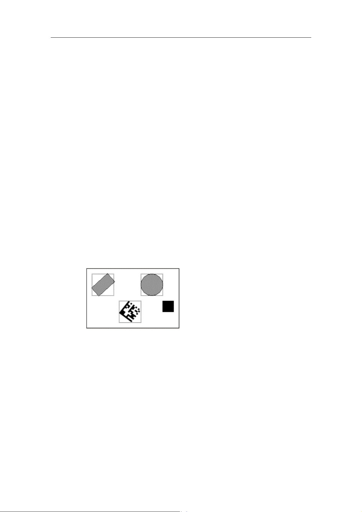
The following figure shows you an illegal constellation for guaranteed read rates:
Two neighboring objects in the image have a rectangular border of a size similar to
that of the code.
Vision Sensor SIMATIC VS 130-2/VS 130-2vcr
A5E00475759-01
1-13
Page 22
Product Overview
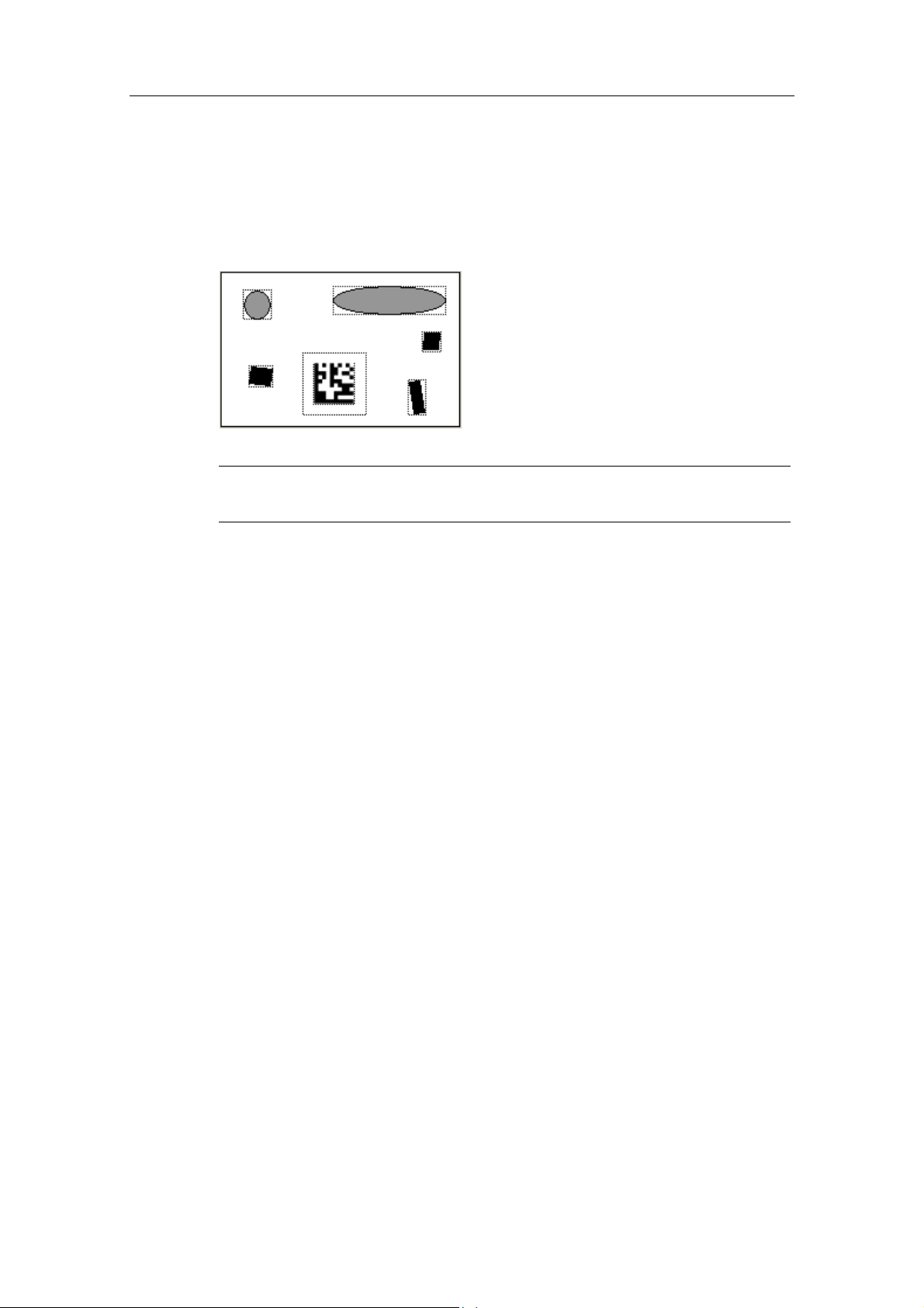
The following figure shows you a legal constellation for guaranteed read rates: All
neighboring objects are clearly of a different size from the code. In this case,
rotation of the code from exposure to exposure would be acceptable since there is
no rectangle of another object that is compatible with the largest possible rectangle
around the code.
Note
Operating and monitoring via the setup support can lead to longer cycle times.
Processing Method for Fast Reading of Data Matrix Codes with a Guaranteed
Read Rate of 20Hz
Settings:
• Speed = high
• Exposure = manual (due to the short processing times, automatic exposure is
not possible with this method.)
These read rates are achieved under the following conditions:
• The illumination must be stable enough so that automatic shutter control is not
necessary.
• The code dimension must not be greater than 20 x 20 dots.
• Since the image is recorded "undersampled", the dots of the code must have a
minimum size of 10 pixels
• The code must be positioned in the sensor image so that there is always a
clearance of at least 3 dots to the edge of the image.
• The code must not make contact with any other objects in the image, the quiet
zone must be kept free.
• To allow the code to be found quickly, there must be no other objects (bus
structures count here as well) in the image with enclosed rectangle and of a
comparable size to the trained code. (See also the two following figures.)
• The diameter of the dots must be uniform over the entire code field. The
contrast between dots and the background must be approximately the same
over the entire code field.
Vision Sensor SIMATIC VS 130-2/VS 130-2vcr
1-14 A5E00475759-01
Page 23

Product Overview
• The image background must have a homogeneous brightness (no textures
such as stripes or grooves etc.).
• The view angle of the sensor to the printed surface must be approaching
vertical (80 to 90 degrees).
Note
Operating and monitoring via the setup support can lead to longer cycle times.
1.7.2 Requirements for QR codes
General Requirements for QR Codes and Legibility
The requirements are as follows:
• It can read codes in which directly adjacent code points have a minimum
distance of 5 pixels and up to a maximum distance of 35 pixels.
• The view angle of the sensor to the surface must be between 70 ° and 90 °.
• The diameter of the dots must be uniform over the entire code field.
• The contrast between dots and the background must be approximately the
same over the entire code field.
• The image background must have a homogeneous brightness (no textures
such as stripes or grooves etc.).
• The following code types are not supported: Micro QR code, Macro QR code
• Due to the limited image resolution, the maximum code dimension 89x89 (for
all sensor heads except 6GF2002-8GB) or 133x133 (for sensor head
6GF2002-8GB) can be read.
Vision Sensor SIMATIC VS 130-2/VS 130-2vcr
A5E00475759-01
1-15
Page 24

Product Overview
Requirements for QR codes for fast reading with guaranteed read rates up to
5 Hz (for all sensor heads except 6GF2002-8GB)
• The code dimension must not exceed 37 x 37.
• To allow the code to be found quickly, there must be no other objects (bus
structures count here as well) in the image with enclosed rectangle and of a
comparable size to the trained code.
• The code must be positioned in the sensor image so that there is always a
clearance of at least 3 dots to the edge of the image.
• The code should not make contact with any other objects in the image (keep
the quiet zone free: 4 dots).
• The dots of the code must have a minimum size of 10 pixels.
• The view angle of the sensor to the printed surface must be approaching
vertical (80 to 90 °).
• The code must not be mirrored compared with the trained code.
• The polarity must be the same as in the trained code.
• The code must have the same dimension as the trained code.
Characteristics of QR code
• Any alignment of the code in the image
• Up to 5 code readings per second
• Reading inverted code images
• Calculation of quality characteristics according to the AIM specification
• Display of the surrounding rectangle around the code position and code mid
point
• Display of the roll angle and tilt angle
Vision Sensor SIMATIC VS 130-2/VS 130-2vcr
1-16 A5E00475759-01
Page 25

Product Overview
1.7.3 Requirements for PDF417 codes
General Requirements for PDF417 Codes and Legibility
The requirements are as follows:
• Codes with a bar width of at least 3 pixels and in which the height of a single
row of symbols is at least 9 pixels can be read.
• The width of the black and white bars must be uniform over the entire code
field.
• The view angle of the sensor to the surface must be greater than 70 °.
• The code should not make contact with any other objects in the image (keep
the quiet zone free: twice the column width).
• Within the code, the ratio of contrast (difference between black and white) to
noise should be at least three and should be very similar over the entire code
field.
• The image background must have a homogeneous brightness (no textures
such as stripes or grooves etc.).
• The code must be positioned in the sensor image so that the entire code
(including start and stop pattern) always has a clearance of at least 3 pixels to
the edge of the image.
• The error correction codes (the lower part of the bar code) must not be
covered.
• The following code types are not supported: Truncated PDF417,
Macro PDF417, Micro PDF417
• At the minimum bar width, each symbol column requires 51 pixels. Along with
the four start and stop patterns, the width of the code with n code columns is:
Width = 51 * (n + 4) pixels. Due to the limited image resolution, codes with up
to a maximum of 40 code rows and up to a maximum of 6 code columns (for all
sensor heads except 6GF2002-8GB) or up to 60 code rows and up to 12 code
columns (for sensor head 6GF2002-8GB) can be read.
Vision Sensor SIMATIC VS 130-2/VS 130-2vcr
A5E00475759-01
1-17
Page 26

Product Overview
Requirements for PDF417 codes for fast reading with guaranteed read rates up
to 5 Hz (for all sensor heads except 6GF2002-8GB)
• The view angle of the sensor to the printed surface must be approaching
vertical (view angle 80 to 90 °).
• To allow the code to be found quickly, there must be no other objects (bus
structures count here as well) in the image with enclosed rectangle and of a
comparable size to the trained code.
• The code dimension must not be greater than 20 rows and 2 columns.
• The bar width must be at least 6 pixels.
• The height of individual symbol rows must be at least 18 pixels.
• There must be no disturbances or overlaps within the code.
• The PDF417 error correction level must be at least 1.
• The polarity must be the same as in the trained code.
Characteristics of the PDF417 code
• Any alignment of the code in the image
• Up to 5 code readings per second
• Reading inverted code images
• Calculating the contrast quality characteristic
• Calculating the unused error correction
• Display of the surrounding rectangle around the code position and code mid
point
Vision Sensor SIMATIC VS 130-2/VS 130-2vcr
1-18 A5E00475759-01
Page 27
2 System Integration
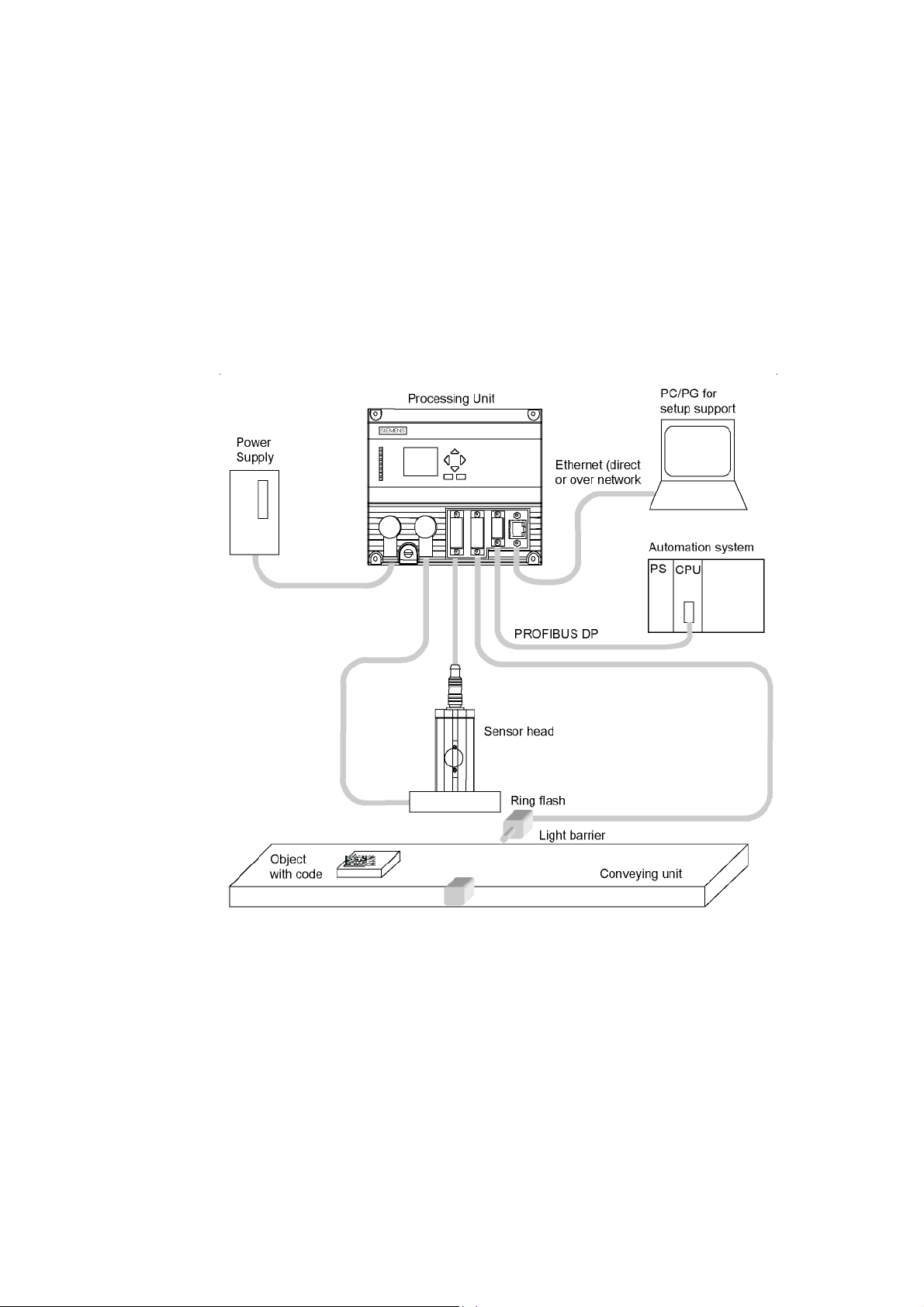
2.1 Design
Vision Sensor SIMATIC VS 130-2/VS 130-2vcr
A5E00475759-01
2-1
Page 28
System Integration
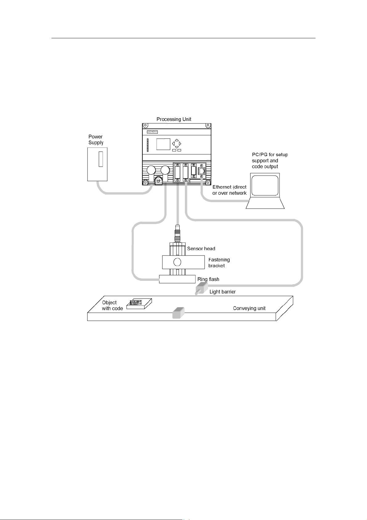
2.2 Application Examples
2.2.1 Reading codes or checking quality in stand-alone mode with output over Ethernet
VS 130-2/VS 130-2vcr reads the codes and outputs them to a PC/PG. The PC or
PG can be connected to the processing unit directly by a crossover cable or over a
network connection.
Vision Sensor SIMATIC VS 130-2/VS 130-2vcr
2-2 A5E00475759-01
Page 29
System Integration
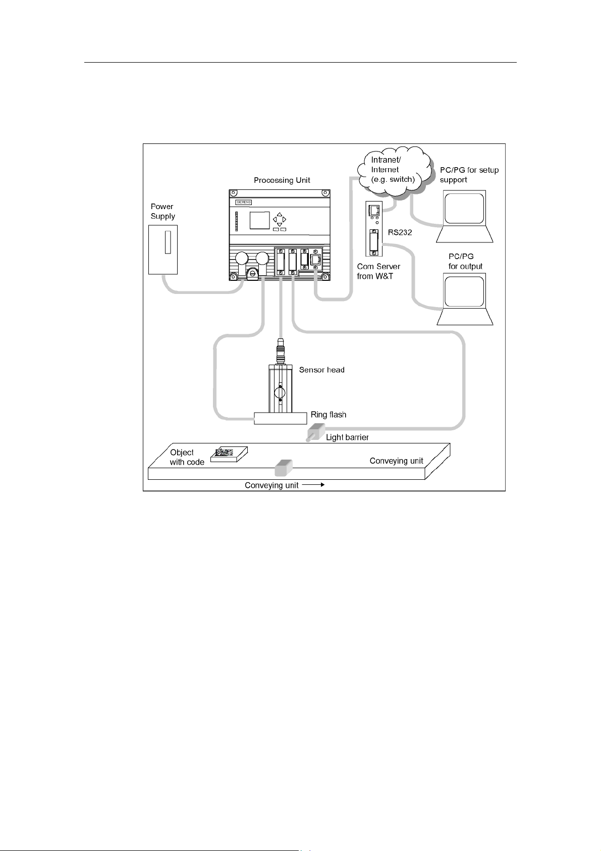
2.2.2 Reading Codes or Quality in Stand-alone Mode with Output over RS-232
The code is output over the RS-232 port of the Com server from WuT. The PC or
PG for setup support is connected to the processing unit over a network (intranet or
Internet).
Vision Sensor SIMATIC VS 130-2/VS 130-2vcr
A5E00475759-01
2-3
Page 30
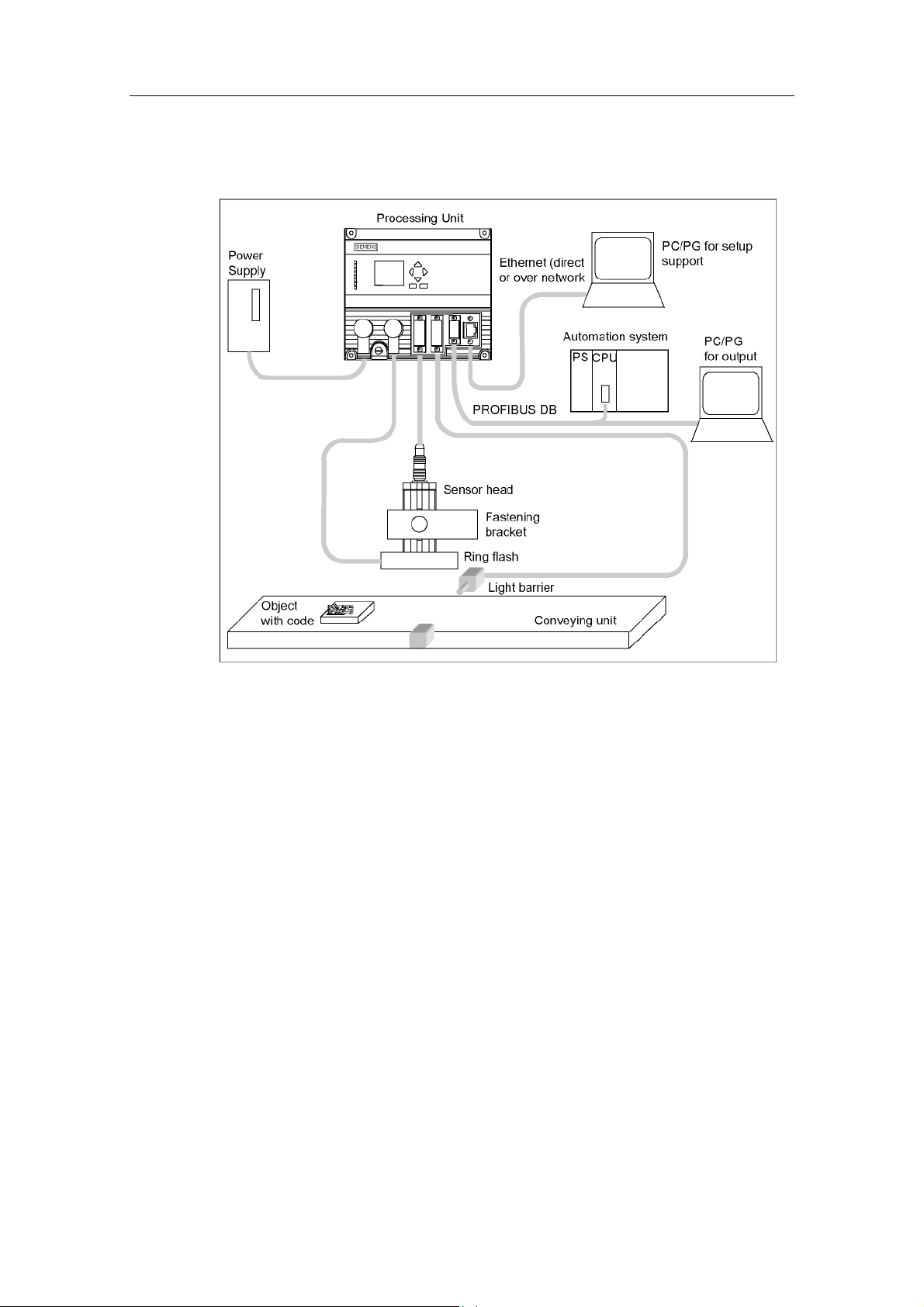
System Integration
2.2.3 Reading Codes or Quality in a PROFIBUS Environment
A PC/PG intended solely for setup is connected over the Ethernet port. Via
PROFIBUS, there is a connection to a PLC and to another PC/PG.
VS 130-2/VS 130-2vcr is controlled over PROFIBUS by the automation system and
the codes output to this automation system or PC/PG once again over PROFIBUS.
Vision Sensor SIMATIC VS 130-2/VS 130-2vcr
2-4 A5E00475759-01
Page 31

System Integration
2.2.4 Reading Codes or Quality in a PROFINET Environment
A PC/PG dedicated for setup is connected over the Ethernet (TCP/IP). There is
also a connection to a PROFINET-capable automation system over the Ethernet.
VS 130-2/VS 130-2vcr is controlled over PROFINET by the automation system.
The code is also output over PROFINET to the automation system.
Vision Sensor SIMATIC VS 130-2/VS 130-2vcr
A5E00475759-01
2-5
Page 32

System Integration
2.2.5 Reading codes or checking quality in a PROFINET environment and outputting over Ethernet
Two PCs or PGs are connected over Ethernet (TCP/IP):
• One is used for setup.
• The other is used to output the read codes.
Note
It is also possible to connect only one PC/PG over Ethernet (TCP/IP). In this case,
the same machine is used for setup and for code output.
A connection to a PROFINET-capable automation system remains over Ethernet.
VS 130-2/VS 130-2vcr is controlled over PROFINET by the automation system.
2.2.6 Mixed operation
In addition to the connection options listed in the sections Reading Codes or
Quality in Stand-alone Mode and over Ethernet to Reading Codes or Checking
Quality in a PROFINET Environment and Outputting over Ethernet, mixed modes
are also possible, for example control over PROFIBUS DP and result output over
RS-232.
Vision Sensor SIMATIC VS 130-2/VS 130-2vcr
2-6 A5E00475759-01
Page 33

3 Installation
3.1 Installing Components for VS 130-2
Step Activity
1 A
Arrange the sensor head so that reflections are kept to a minimum. The angle of its central
axis should be typically 15° from vertical (angle α) (permitted range of angles for data matrix
and Vericode: 0 ≤ α ≤ 40°, for QR and PDF417 code: 0 ≤ α ≤ 30°).
Vision Sensor SIMATIC VS 130-2/VS 130-2vcr
A5E00475759-01
3-1
Page 34

Installation
Step Activity
1b If there is still too much reflection at an angle of 15°, select an arrangement in which the
sensor head and the ring flash are not concentric.
Note:
The mechanism for mounting the ring flash is not supplied with the product.
If the ring flash does not meet your requirements, please contact your sales partner who will
be able to recommend other suppliers of lighting for the VS 130-2C.
1c
2 Install the processing unit so that it is easily accessible for the operator.
3
4 Start the setup support on the PG/PC, and switch the processing unit to the Adjust mode. You
With both arrangements, maintain a clearance between the end of the sensor head and the
code to be read that is suitable for the lens you are using.
Caution:
If you have a large code area and the sensor is inclined at a large angle to the code area and
there is only a short distance between the sensor and code area, this can lead to image
distortion and diminished recognition performance.
Install the external triggering unit, for example a light barrier.
then see an image as seen by the sensor head.
• Check the trigger signal. by selecting the "Trg. only" check box in the "Read settings"
group of the "Adjust" task. Check whether VS 130–2 can read the codes with the sensor
head and ring flash in the current position. If necessary, correct the trigger point and/or
position of the sensor head.
• Select suitable values for the shutter speed and brightness. The image should not be too
bright.
Caution: If Exposure is set to Auto V1 or Auto, the code must remain fully in the image for at
least 100 ms.
As soon as after "Recognition" the message "Successfully finished" appears, the code has
been successfully decoded. You will see the result of the read in the "Result" box.
Vision Sensor SIMATIC VS 130-2/VS 130-2vcr
3-2 A5E00475759-01
Page 35

Installation
3.2 Wiring Components
Connect the processing unit with the other components using the connectors on
the front panel.
Port Pin Assignment of the Processing Unit
!
Do not connect or disconnect cables when the power supply is on.
Apart from the Ethernet cable, the cables are supplied with the product (See
Components of the Product).
Warning
Attention
!
Grounding the VS 130-2/VS 130-2vcr cancels the ungrounded installation of the
power unit used to operate the VS 130-2/VS 130-2vcr.
Connector Connector
Label
Functional earth - Screw terminal - - -
Power supply IN 24 V DC Circular connector M12 4 0.56 mm2 Pin
Illumination Unit LAMP Circular connector M12 4 0.23 mm2 Socket
Sensor head
(shielded cable)
I/O DI/DO D-sub 15 0.14 mm2 Socket
PROFIBUS DP DP D-sub 9 - Socket
Ethernet Ethernet RJ45 8 - Socket
* The supplied ferrite ring must be fixed to the sensor cable (approx. 50 mm from connector to
evaluation unit).
SENSOR HD D-sub * 26 0.09 mm2 Socket
Type Number
of pins
Cable Cross
Section
Type
Vision Sensor SIMATIC VS 130-2/VS 130-2vcr
A5E00475759-01
3-3
Page 36

Installation
Step Activity
1 Read the guidelines for preventing electrical interference (see Guidelines for Preventing
Electrical Interference).
2 Connect the processing unit to the sensor head and the lighting unit with the cables.
3 If you do not evaluate the result bits READ, MATCH, N_OK over PROFIBUS DP: Connect the
digital outputs READ, MATCH, N_OK as described in Control Signals.
4 Connect the trigger signal via the TRG digital input.
5 If you intend to control the SIMATICVS 130-2/VS 130-2vcr with a PLC, connect the other digital
inputs and outputs as described in Control Signals.
6 Connect functional ground of the processing unit to chassis ground (diameter of the ring: (M5,
cable cross section 1.5 mm
7 Connect the processing unit to the 24 V power supply (2 A).
8
Connect the PC/PG to the processing unit via Ethernet.
2
).
Note
The DC load power supply must meet the following requirements:
Only low voltage less than or equal to 24 V DC safely isolated from the power
supply network must be used for the load current supply. Safe isolation can be
implemented, for example, by adhering to the specifications
1. VDE 0100-410 / HD 384-4-41 S2 / IEC 60364-4-41
(functional low voltage with safe isolation) or
2. VDE 0805 / EN 60950 / IEC 60950
(as safety extra-low voltage SELV) or VDE 0106 Part 101.
Note
The supply chassis of the I/O and CPU must be connected to the supply chassis of
the processing unit.
Vision Sensor SIMATIC VS 130-2/VS 130-2vcr
3-4 A5E00475759-01
Page 37

Installation
3.3 Guidelines on Interference-Proof Installation
To avoid interference, you must shield your system. Low-frequency (LF) and highfrequency (HF) interference signals can result in an incorrect response if the
system is badly grounded or not shielded.
Interference signals can be caused, for example, by switching relays or contactors
(high rates of change in current or voltage, HF interference signals) or by different
ground potentials between two parts of a system (LF interference signals).
Using / Installing Interference-Proof Cable
• Always use the included patch cord to connect the sensor head.
• All plug-in connections must be secured by screws or a locking mechanism.
• Signal lines must not run parallel to power cables. A separate cable channel
must be used with a minimum clearance of 50 cm from power cables.
Note
For more detailed information, refer to the installation manual SIMATIC S7-300
Programmable Controller, Hardware and Installation in the section on "Wiring".
3.4 Guidelines for Installing PROFIBUS DP or PROFINET I/O
If you are using PROFIBUS DP or PROFINET I/O (to control the device and/or to
transfer the results) the installation and configuration guidelines must be kept to.
You will find this information in the installation manual SIMATIC S7-300
Programmable Controller, Hardware and Installation.
Vision Sensor SIMATIC VS 130-2/VS 130-2vcr
A5E00475759-01
3-5
Page 38

Installation
Vision Sensor SIMATIC VS 130-2/VS 130-2vcr
3-6 A5E00475759-01
Page 39

4 Commissioning
4.1 Introduction
You can operate the Vision Sensor SIMATIC VS 130-2/VS 130-2vcr interactively or
controlled by signals:
• In this chapter, you will learn about interactive operation using the operator
control and display field of the evaluation unit.
• The section Process interfacing explains the options open to you for signal-
controlled operation.
Note
The setup support for VS 130-2/VS 130-2vcr is described in detail in the Online
Help for Setup Support.
4.2 Turning on the Device
Turn on the power on the processing unit. The texts "Booting... SIMATIC V ..." and
then "Firmware Version V..." with the current firmware version appear on the
display.
The VS 130-2 or VS 130-2vcr then runs the following tests:
• Test of the sensor head
• Test of the stored settings and code data
• If applicable, check whether data can be exchanged from and to PROFIBUS
(this check is made if you have selected "DP" for one or more of the following
signal paths: Output of the result string, feeding the trigger signal to the
processing unit, signal path for DISA, SEL0, SEL1, SEL2, SEL3, TRN, RES,
IN_OP, TRD, RDY, READ, MATCH, N_OK).
• Test of the Ethernet connection
• If applicable, check for the connection to PROFINET and to Ethernet RS-232
converter or TCP server and to the PC/PG on which diagnostic information will
be stored (over TCP/IP)
Vision Sensor SIMATIC VS 130-2/VS 130-2vcr
A5E00475759-01
4-1
Page 40

Commissioning
If there are no errors in the self-test, either the ADJUST menu or the RUN menu or
the STOP menu is displayed depending on the status when you last shut down.
• "ADJUST" menu:
• "RUN" menu:
• "STOP" menu level
Note
Apart from controlling from the processing unit, you can also control
VS 130-2/VS 130-2vcr with the setup support, see Operating using the
Setup Support.
Vision Sensor SIMATIC VS 130-2/VS 130-2vcr
4-2 A5E00475759-01
Page 41

Commissioning
4.3 Control and Display Panel
The operator is guided by menus in the display panel.
• The menu items appear in the first three lines of the display panel. The cursor
">" points to the selected menu item.
• In the fourth line of the display panel, you can see which buttons of the control
panel are currently available (OK, ESC, V, W,
control panel, you can navigate within menus and from one menu to another:
, ). Using the buttons of the
- With the arrow buttons "V" and "W", you can move the cursor up and down
and select the menu command you require.
- With the "OK" button, you confirm your selection and move on to the next
step.
- With the "ESC" button, you open the previous menu.
Description of the LEDs
LEDs Function
SF Group error
POWER Power supply turned on
TRAINED Trained:
READY Ready:
READ Evaluation result: Code was localized and decoded.
MATCH Evaluation result: Code matches learned code.
N_OK • Code was not legible.
BF Bus error on PROFIBUS or PROFINET
• In Run:
from: Selected code has not been trained
On: Selected code has been trained
• In Training (TRN=1):
from: Training active
On: Acknowledgment signal (RDY=0)
• from: Device startup or SIMATIC VS 130-2/VS 130-2vcr in Stop
• On: SIMATIC VS130-2/VS 130-2vcr in run
Vision Sensor SIMATIC VS 130-2/VS 130-2vcr
A5E00475759-01
4-3
Page 42

Commissioning
Setting the number values
You select the places of a value with the arrow buttons " " and " ".
You change the value of a place in the number with the arrow buttons "V" and "W".
The speed at which the numeric value changes depends on how long you press
the arrow buttons. As soon as you release the arrow buttons, the rate of change
returns to the slowest level again.
Vision Sensor SIMATIC VS 130-2/VS 130-2vcr
4-4 A5E00475759-01
Page 43

Commissioning
4.4 Adjusting the Sensor with the Setup Support
Before you commission the SIMATIC VS 130-2/VS 130-2vcr, you must adjust the
sensor head correctly. using a Web-based setup support. You then see an image
as seen by the sensor head. For more detailed information on the setup support,
refer to the online help.
Step Activity
1
2
3
4
5
6
7
8
9
1. Switch on the PC or PG with the Internet Explorer.
2. Turn on the processing unit.
3. Establish the TCP/IP connection between the processing unit and the PC/PG. You can
either do this directly with a crossover cable or by including the processing unit in an existing
network. Both options are described in detail in the online help.
4. Enter the address of the processing unit the Internet Explorer.
Result:
Once the setup support has started, the sensor field of view is displayed on your PC/PG monitor.
The displayed image is updated several times per second.
Adjusting the Sensor
1. Bring the code into the image.
2. Set a sharp image by adjusting the distance between the end of the sensor head and the
code correctly.
3. Correct the shutter speed and the brightness if necessary or use one of the automatic
modes (Auto V1 or Auto).
4. Minimize reflected light by viewing the code at a slight angle.
5. Activate the "Triggered only" check box to test the trigger signal and the trigger settings
(trigger source).
6. Tune further settings as required.
Note:
If you have too many errors, clean the lens and diffuser with a lint-free cloth.
• Secure the sensor and then check the correct sensor position.
• Make other parameter settings.
• Check the read result.
• Set the parameters to specify the process interface.
• Train the codes, if already known.
• Change to the processing mode (RUN).
Analyze any errors that may occur.
Vision Sensor SIMATIC VS 130-2/VS 130-2vcr
A5E00475759-01
4-5
Page 44

Commissioning
Vision Sensor SIMATIC VS 130-2/VS 130-2vcr
4-6 A5E00475759-01
Page 45

5 Operator Input
5.1 Overview
There are two basic ways of controlling the VS 130-2/VS 130-2vcr:
• Using the Setup Support
• Using the Processing Unit
With a few exceptions, you can set all the parameters with either method. This is
illustrated based on the example of the "IP Mode" parameter:
• In the setup support, you will find this parameter in the "Connections" task in
the "Interfaces" tab in the "Ethernet" group in the "IP Mode" drop-down list box.
• On the processing unit, it is available at the ADJUST menu level (Connect >
Ports > Ethernet > IP Mode).
5.2 Working with the Processing Unit
The display of the processing unit is used to display the currently read code and to
navigate through the menus and make entries.
Example of the display of a code:
C 01 RUN √
=SERIES 7
OK:Menu
Note
In processing mode, it is not the currently read code that is displayed on the
processing unit when verifying but the string "Verifying=" followed by 4 quality
grades. These belong to the following quality characteristics: 1. Grade belongs to
the quality characteristic symbol contrast, 2. grade belongs to the quality
characteristic print growth, 3. grade belongs to the quality characteristic axial nonuniformity, 4. grade belongs to the quality characteristic unused error correction.
There are three menu levels:
• RUN
• Adjust
• STOP
Vision Sensor SIMATIC VS 130-2/VS 130-2vcr
A5E00475759-01
5-1
Page 46

Operator Input
The following table contains the menus of the RUN menu level.
Unless a temporary PROFIBUS DP or PROFINET IO error has occurred
(see Error Messages), the "Info" menu appears as follows:
Menu Meaning
Code Select the code number
STOP Processing and change to the STOP menu level
Info
ResetStat
Information function
Reset all statistical information (identical parameter to ResetStat in the
Options>Decode menu)
Vision Sensor SIMATIC VS 130-2/VS 130-2vcr
5-2 A5E00475759-01
Page 47

Operator Input
If one or more PROFIBUS DP or PROFINET IO errors have occurred
(see Error Messages), the "Info" menu appears as follows:
Vision Sensor SIMATIC VS 130-2/VS 130-2vcr
A5E00475759-01
5-3
Page 48

Operator Input
The following table lists the menus of the ADJUST menu level.
Menu
STOP Exits the ADJUST menu level
Adapt (only with Exposure = Manual) exposure adaptation
Trigger Trg.only An image is captured only on the trigger signal.
Auto (default) The images are acquired continuously.
Delay
Distort Correction of the image distortion caused by the lens
LightSrc. Specifies a light source (only in multilight mode)
Meaning
If you have made changes in the Adjust menu, you can save or discard them.
The processing unit changes to the STOP mode.
Specification of a maximum speed: Time by which the trigger signal will be
delayed (identical parameter to Delay in the Options>Integrate>Trigger menu)
Default: 0 ms
Default:
• Sensor head 6GF2 002-8DA01: 130
• Sensor head 6GF2 002-8EA01: 50
• Sensor head 6GF2 002-8FA01: 0
• Sensor head 6GF2 002-8CB: 0
• Sensor head 6GF2 002-8GB: 0
The menus of the STOP menu level are listed in the following table.
Menu Meaning
Adjust Changes to the setup mode
Connect Sets global connection parameters (interfaces, integration, result string)
Train Train a code
RUN Start evaluation of a code
Options Sets global device parameters (decoding, illumination and image capture,
diagnostics)
Maintain Delete trained codes and reset all parameters to their default values
Vision Sensor SIMATIC VS 130-2/VS 130-2vcr
5-4 A5E00475759-01
Page 49

Operator Input
The following four schematics provide you with an overview of all the parameters of
the VS 130-2 that can be set in the Connect and Options menus.
Vision Sensor SIMATIC VS 130-2/VS 130-2vcr
A5E00475759-01
5-5
Page 50

Operator Input
Vision Sensor SIMATIC VS 130-2/VS 130-2vcr
5-6 A5E00475759-01
Page 51

Operator Input
Vision Sensor SIMATIC VS 130-2/VS 130-2vcr
A5E00475759-01
5-7
Page 52

Operator Input
Vision Sensor SIMATIC VS 130-2/VS 130-2vcr
5-8 A5E00475759-01
Page 53

Operator Input
The following three schematics provide you with an overview of all the parameters
of the VS 130-2vcr that can be set in the Connect and Options menus.
Vision Sensor SIMATIC VS 130-2/VS 130-2vcr
A5E00475759-01
5-9
Page 54

Operator Input
Vision Sensor SIMATIC VS 130-2/VS 130-2vcr
5-10 A5E00475759-01
Page 55

Operator Input
Vision Sensor SIMATIC VS 130-2/VS 130-2vcr
A5E00475759-01
5-11
Page 56

Operator Input
The following table describes all the parameters of the Connect menu.
Parameter Path Possible
Values
Ports
Pulsetime Ports>DI/DO 5 to 999 30 Pulse time of the digital outputs
Address
(not active, if
IP Mode =
PNIO)
(only for
VS 130-2)
Timeout
(not active, if
IP Mode =
PNIO)
(only for
VS 130-2)
Pulsetime
(not active, if
IP Mode =
PNIO)
(only for
VS 130-2)
Swap
(not active, if
IP Mode =
PNIO)
(only for
VS 130-2)
Devname
(not active, if
IP Mode =
PNIO)
(only for
VS 130-2)
Timeout
(not active, if
IP Mode =
PNIO)
(only for
VS 130-2)
Pulsetime
(not active, if
IP Mode =
PNIO)
(only for
VS 130-2)
Ports>DP 1 to 125 7 Address on PROFIBUS DP
Ports>DP 100 to 2000 500 Handshake monitoring time in ms
Ports>DP 5 to 999 30 Pulse time of the digital outputs
Ports>DP S7, No S7 Specifies the byte order for data
Ports>PNIO String (0 to 9, A
to Z, a to z, ".",
"-"). The string
must match the
conventions of
the domain
name system.
Ports>PNIO 100 to 2000 500 Handshake monitoring time in ms
Ports>PNIO 5 to 999 30 Pulse time of the digital outputs
Default setting Meaning
READ, MATCH, N_OK in ms on the
DI/DO interface
READ, MATCH, N_OK in ms when
output is over PROFIBUS DP
types with a width of 16 bits or more:
1. S7: big endian
2. No: little endian
VS 130-2 Name of the device on PROFINET
Note: PROFINET is not case
sensitive
READ, MATCH, N_OK in ms when
output is over PROFIBUS I/O
Note: For the pulse time, select a
higher value than for the update time
of the PROFINET IO system in HW
Config.
Vision Sensor SIMATIC VS 130-2/VS 130-2vcr
5-12 A5E00475759-01
Page 57

Operator Input
Parameter Path Possible
Values
Swap
(not active, if
IP Mode =
PNIO)
(only for
VS 130-2)
IP mode Ports>Ethernet DHCP
IPAddress
(not
modifiable, if
IP Mode =
DHCP)
IP Mask
(not active, if
IP Mode =
DHCP)
Gateway
(not active, if
IP Mode =
DHCP)
MAC Info Ports>Ethernet Cannot be
IPAddress Ports>
IP Port Ports>
Ports>PNIO S7
no
Manual
DHCPSERV
PNIO (only for
VS 130-2)
Ports>Ethernet xxx.xxx.xxx.xxx
(xxx=0 to 255)
Ports>Ethernet 255.255.xxx.yyy 255.255.255.0 The subnet mask indicates which
Ports>Ethernet xxx.xxx.xxx.xxx
(xxx=0 to 255)
modified
xxx.xxx.xxx.xxx
TCP/RS-232
TCP/RS-232
(xxx=0 to 255)
device-specific 8000 RS-232 port of the Ethernet RS-232
Default setting Meaning
S7 Specifies the byte order for data
types with a width of 16 bits or more:
• S7: big endian
• No: little endian
DHCP Assignment of the IP address to the
processing unit in the network:
• DHCP: Automatic (DHCP =
Dynamic Host Configuration
Protocol)
• Manual: Manual
• DHCPSERV: The processing
unit can assign an IP address to
a PC connected by a crossover
cable if the PC obtains its IP
address automatically (DHCP
client).
• PNIO: Automatic by the I/O
controller
192.168.0.42 IP address of the processing unit
(An IP address consists of four
numbers separated by periods with
each number being in a range from 0
to 255.)
part of the IP address specifies the
network and which part specifies the
processing unit:
For xxx.yyy, binary requires that the
left part be made up of ones without
a gap and the right part be made up
of zeros without a gap. Example:
11111111.10100000 is not
permitted.
Note also: yyy <= 254
192.168.000.255 IP Address: IP address of the
network node that can establish
connections outside of the current
subnet
Devicedependent
192.168.000.043 IP address of the Ethernet RS-232
The MAC address (Media Access
Control) is the hardware address of
each network device and is used to
identify the device uniquely in the
network.
converter or of the PC/PG on which
a TCP server runs.
converter or IP port of the PC/PG on
which a TCP server runs
Vision Sensor SIMATIC VS 130-2/VS 130-2vcr
A5E00475759-01
5-13
Page 58

Operator Input
Parameter Path Possible
Values
Timeout Ports>
TCP/RS-232
IPAddress
(only for
VS 130-2)
Port
(only for
VS 130-2)
Timeout
(only for
VS 130-2)
Ports>
Arch/MMI
Ports>
Arch/MMI
Ports>
Arch/MMI
0 to 3600 0 • 0: There is no transfer of cyclic
xxx.xxx.xxx.xxx
(xxx=0 to 255)
Device-specific 8765 Corresponding port of this server
0 to 3600 10 • 0: There is no transfer of cyclic
Default setting Meaning
monitoring frames to determine
whether the connection still
exists between the processing
unit and the Ethernet RS-232
converter or the PC/PG on
which a TCP server runs.
• Otherwise: Time in seconds
after which a monitoring frame is
sent to determine whether the
connection still exists between
the processing unit and the
Ethernet RS-232 converter or
the PC/PG on which a TCP
server runs. The check is
implemented by sending the
"Idling string" ("Connections"
dialog "Part 3/3. Result and
String") to the recipient at the
intervals set with the parameter.
If the check fails, an error is
output (only when the
processing unit is in RUN or
Train) and the connection is
reestablished.
192.168.000.045 IP address of the server for
diagnostic information
monitoring frames to check the
connection between processing
unit and server.
• Otherwise: Time in seconds
after which a monitoring frame is
sent to check the connection
between processing unit and
server. If the server does not
respond to this frame within the
monitoring time, an error is
output (only when the
processing unit is in RUN or
Train) and the connection is
reestablished.
Vision Sensor SIMATIC VS 130-2/VS 130-2vcr
5-14 A5E00475759-01
Page 59

Operator Input
Parameter Path Possible
Values
Integrate
Source Integrate>
Trigger
String
(only if
Source=
TCP/RS-
232)
Delay Integrate>
String Integrate DP or PNIO
Result Integrate DP or PNIO
Control Integrate DP or PNIO
DiagImage
(only for
VS 130-2)
DiagReport
(only for
VS 130-2)
Integrate>
Trigger
Trigger
Integrate None
Integrate None
Endless
DI/DO
DP or PNIO
(only for
VS 130-2)
TCP/RS-232
ASCII
characters
0 to 9999 ms 0 ms Here, you specify the time by which
(only for
VS 130-2)
TCP/RS-232
None
(only for
VS 130-2)
DI/DO
None
(only for
VS 130-2)
DI/DO
Arch/MMI
Arch/MMI
Default setting Meaning
DI/DO Here, you set the port over which the
trigger signal is sent to the
processing unit.
M If the string specified here is sent
over the RS-232 port of an RS-232
Ethernet converter or a TCP server,
the processing unit generates a
trigger signal.
the trigger signal will be delayed in
ms (Identical parameter to Delay in
the Adjust menu).
None Here, you enter the port over which
the result string is output.
DI/DO Here, you specify the port over which
the result bits OK, N_OK, READ,
and MATCH are output.
DI/DO Here you specify the port for the
DISA, SEL0, SEL1, SEL2, SEL3,
TRN, RES, IN_OP, TRD, RDY
signals.
None Here, you specify whether the
currently captured image will be sent
to a server when an error occurs.
None Here, you specify whether the
corresponding data record will be
sent to a server when an error
occurs.
Vision Sensor SIMATIC VS 130-2/VS 130-2vcr
A5E00475759-01
5-15
Page 60

Operator Input
Parameter Path Possible
Values
String
option String>Filter Off
Position
ID
StartPos
(only if
String>
Filter
>Option=
Position)
Length
(only if
String>
Filter
>Option=
Position)
Separator
(only if
String>
Filter>
Option=ID)
ID
(only if
String>
Filter>
Option=ID)
String>Filter >=1 1 Position, starting at which the
String>Filter >=1 1 The part string consists of as many
String>Filter ASCII
characters
String>Filter ASCII
characters
Default setting Meaning
Off • Off: No character in the read
codes is suppressed. Nor are
any characters added.
• Position: Only part of the string
of the read codes is taken into
account. You specify this part
with the StartPos and Length
parameters.
• ID : Only parts of the string of
the read codes are taken into
account. You specify which
parts using the Separator and ID
parameters.
characters of a part string are output.
characters as you specify here.
+ Separators
- The substring start is identified by
the ID. If several sequences are
identified by the ID, only the first one
is used.
Vision Sensor SIMATIC VS 130-2/VS 130-2vcr
5-16 A5E00475759-01
Page 61

Operator Input
Parameter Path Possible
Values
Format String See "Meaning" %s Content and format of the string to
ReadErr String>
Messages
FilterErr String>
Messages
See "Meaning" Read Err (%s) Content and format of the string to
Freely
selectable
character string
Default setting Meaning
be output
The string can be a maximum of 100
bytes long and consists of any
combination of the following
elements:
• Characters whose ASCII
equivalent is between 01H and
FFH (%% causes a percentage
character to be displayed)
• Formatting instructions for
output of variables
A formatting instruction has the
following structure:
% [number of places] variable
{selection of variables}
Here, square brackets mean the
information is optional Braces mean
that the exactly one value must be
selected from within the braces The
following formatting instructions are
possible:
• %s
• %[03]q{0|1|2|3}
• %Q{0|1|2|3|4}
• %[03]p{0|1|2}
• %[{04|05}]c
• %u
• %U
• %l
be output with read errors
The string can be a maximum of 100
bytes long and consists of any
combination of the following
elements:
• Characters whose ASCII
equivalent is between 01H and
FFH (%% causes a percentage
character to be displayed)
• Formatting instructions for
output of variables
The following formatting instructions
are possible:
• %s
• %c
"%s" stands for the textual
description of the probable cause of
the error in English, "%c" for a
decimal number with the same
information
Filter error Text for the situation when the
values for StartPos or ID for the
current part do not occur in the read
code
Vision Sensor SIMATIC VS 130-2/VS 130-2vcr
A5E00475759-01
5-17
Page 62

Operator Input
Parameter Path Possible
Values
MatchErr String>
Messages
FormatErr String>
Messages
See "Meaning" Match error (%s) Content and format of the string to
Freely
selectable
character
string
Idle Str. String Freely
selectable
character
string
Default setting Meaning
be output with a match error
The string can be a maximum of 100
bytes long and consists of any
combination of the following
elements:
• Characters whose ASCII
equivalent is between 01H and
FFH (%% causes a percentage
character to be displayed)
• Formatting instruction for output
of variables
The following formatting instruction is
possible:
• %s (result string)
Format error Text for errors occurring in the
"Format" parameter
\r\n
String to determine whether the
connection still exists between the
processing unit and the Ethernet RS232 converter or the PC/PG on
which a TCP server runs. It is
transferred cyclically. Select this so
that it can be clearly distinguished
from the result string by the recipient.
The string can be a maximum of 100
bytes long.
Vision Sensor SIMATIC VS 130-2/VS 130-2vcr
5-18 A5E00475759-01
Page 63

Operator Input
The following table describes all the parameters of the Options menu.
Parameter Path Possible
Values
Decode
ResetStat Decode - - Resets all the statistical information
Task Decode Read
Match
Verify
MATCH
(only if Decode>
Task=
Match)
Speed Decode High
StartPos
(only if Decode>
Task=Match and
Decode> Match>
Option>
Match= Position)
Length
(only if Decode>
Task=Match and
Decode> Match>
Option>
Match= Position)
Separator
(only if Decode>
Task=Match and
Decode> Match>
Option>
Match=ID)
ID
(only if Decode>
Task=Match and
Decode> Match>
Option>
Match=ID)
Decode>
Match>
Option
Decode>
Match
Decode>
Match
Decode>
Match
Decode>
Match
All
Position
ID
Medium
Low
>=1 1 The first character from the
>=1 1 The length of the reference string is
ASCII
characters
ASCII
characters
Default setting Meaning
(identical parameter to ResetStat in
the RUN menu)
READ Here, you set the task you want to
execute with VS 130-2/VS 130-2vcr:
• Read: Read codes
• Match: Compare the entire code
or parts of it with a trained code
• Verify: The quality values of the
currently read code to which the
quality codes of a trained code
relate
All • All: All the characters of the
codes are compared with all the
characters of the trained code.
• Position: The string resulting
from "StartPos" and "Length" is
compared.
• ID : The string resulting from
"Separator" and "ID" is
compared.
Low Here, you specify the processing
method and duration of decoding.
reference string is entered here.
entered here.
+ The substring extends as far as the
first separator from the "Separators"
input box to occur or to the end of
the code if there are no separators
from the "Separators" box.
- Here, you enter the Match ID with
which the part string will be started.
Vision Sensor SIMATIC VS 130-2/VS 130-2vcr
A5E00475759-01
5-19
Page 64

Operator Input
Parameter Path Possible
Values
Cycletime Decode 30 (75 with
highresolution
sensor) to
9999 ms
VCompress
(only for
VS 130-2vcr)
Key (only if Decode
>License >Demo
=Off)
(only for
VS 130-2vcr)
Check
(only for
VS 130-2vcr)
LIGHT
Type LIGHT IR
Exposure LIGHT Manual
Shutter
(only when
Exposure=
Manual)
Brightness
(only when
Exposure=
Manual)
MaxShutt.
(only when
Exposure=
Auto)
Decode None,
Numeric,
Alphanum
Decode>
VLicense
Decode>
VLicense
LIGHT 1 to 20000 µs 200 µs Enter the shutter speed of the sensor
LIGHT 10 to 500 200 Here, you set the brightness.
LIGHT 5 to 20000 10 000 Upper limit for the shutter speed of
Cannot be
modified
Valid, Invalid - Displays the status of the license
Red
Other
Auto
Auto V1
Default setting Meaning
2000 ms Here, you enter the upper limit for
None Here, you set the character set that
Devicedependent
Red Here, you enter the type of
Auto Here, you set the shutter control:
the processing time.
was used in the Vericode to be read,
to allow data compression if
necessary:
• None: Maximum character set
Every character requires 8 bits.
• Alphanum: Only upper case
letters, numbers and a few
special characters are used.
Every character requires 6 bits.
• Numeric: Only numbers are
used. Every character requires 4
bits.
Displays the license key (8
hexadecimal numbers)
key.
• Valid: Valid Vericode license
• Invalid: Invalid Vericode license
illumination being used.
• Manual: Manual
• Auto: Automatic
• Auto V1: Automatic as in
VS 130-2 V1.x (compatibility
mode)
in µs.
the sensor in µs
Vision Sensor SIMATIC VS 130-2/VS 130-2vcr
5-20 A5E00475759-01
Page 65

Operator Input
Parameter Path Possible
Values
MaxBright
LIGHT 10 to 500 500 Upper limit for the brightness
(only when
Exposure=
Auto)
ShuttOff
(for VS 130-2vcr:
LIGHT -10000 to
10000 µs
only when
Exposure=
Auto
for VS 130-2:
only when
Exposure=
Auto and ShuttOff-
Flag= On)
Diagnostics
Buffer Diagnose>
Ring, Stack Ring • Type of image buffer:·
Logging>
Images
Reasons Diagnose>
Logging>
Images
Trigger, NOK,
Read, Match,
No Match,
Train
Record Diagnose>
Logging>
Image, +/- 1
Image
Images
Save Next
(only for
VS 130-2)
Buffer Diagnose>
Diagnose>
Logging>
Images
On, Off Off • On: The image belonging to the
Ring, Stack Ring • Ring: When the diagnostic
Logging>
Report
Default setting Meaning
0 µs Enter the value here by which the
automatically calculated shutter time
will be changed.
Note: The maximum exposure time
is not exceeded.
• Ring: When the buffer contains
50 entries, entries 1,2 ... are
overwritten.
• Stack: When the buffer contains
50 entries, no further entries are
made.
N_OK, Read und
Train
Here, you specify what causes an
image to be saved.
Image • Image: If one or more of the
causes listed above occurs, the
current image is saved.
• +/- 1 Image: Not only the current
image but also the previous and
next image are saved.
next NOK event is saved
permanently in the EPROM.
buffer contains 15000 entries,
entries 1,2 ... are overwritten.
• Stack: When the diagnostic
buffer contains 15000 entries,
no further entries are made.
Vision Sensor SIMATIC VS 130-2/VS 130-2vcr
A5E00475759-01
5-21
Page 66

Operator Input
Parameter Path Possible
Values
Save Next
(only for
VS 130-2)
Entries
(only for
VS 130-2)
Clear
(only for
VS 130-2)
Timebase Diagnose>
SNTP IP
(Only when
Timebase= SNTP)
Update Diagnose>
Extras (only for VS 130-2)
Multi Extras>
LightSrc.
(Only if Multi= On)
Diagnose>
Logging>
Report>
Permanent
Diagnose>
Logging>
Report>
Permanent
Diagnose>
Logging>
Report>
Permanent
Logging
Diagnose>
Logging
Monitor
Light
Extras>
Light
On, Off Off As soon as the function is enabled,
10 to 2000 2000 Number diagnostic data records that
- - Delete all the diagnostic entries
PC, SNTP PC/ Here, you specify the source for the
xxx.xxx.xxx.xxx
(xxx=0 to 255)
On
Off
On, Off Off • On: Mode in which you specify
Lamp1, …
Lamp4
Default setting Meaning
as many diagnostic entries as you
specify in "Entries" are saved in the
EPROM. Existing entries are deleted
when you switch over to On. If the
diagnostic buffer in the EPROM
reaches the number of permanently
storable diagnostic data records, no
further entries are made.
Note: Deleting takes several
seconds.
can be stored on the EPROM
stored on the EPROM
Note: Deleting takes several
seconds.
time stamp of the diagnostic events.
192.168.000.044 IP address of the SNTP server
On Here, you specify whether images
and the events are saved in
processing mode and whether a live
image is displayed:
• On: Images and events are
saved, live image
• Off: Images and events are not
saved, no live image
the lamp to be used for lighting.
In this mode, the result bits
cannot be output over the DI/DO
interface.
The information on which lamp
to use is stored along with the
code data.
When reading without previous
training (Code number=Auto),
the lamp currently set in the
parameters will be used.
Lamp1 Default lamp to be used for the
image capture
Vision Sensor SIMATIC VS 130-2/VS 130-2vcr
5-22 A5E00475759-01
Page 67

Operator Input
Parameter Path Possible
Values
Use ROI
(only if Exposure=
Auto)
ShuttOff
(only if Exposure=
Auto)
Multicode Extras On, Off Off • On: Mode in which several
Set 1, …
Set 14
(only if Multicode=
On)
Use ROI Extras>
Extras>
Light
Extras>
Light
Extras>
Codesets
SpeedUp
On, Off Off • On: In automatic shutter control,
On, Off On ShuttOff-Flag:
Multiple
selection of
codes 1 to 14
(maximum 5)
On, Off Off • On: During image processing,
Default setting Meaning
to calculate the optimum lighting
parameters, not the entire image
area but only the selected
region of interest is used.
• Off: In automatic shutter control,
to calculate the optimum lighting
parameters, the entire image
area is used.
• On: The automatically
calculated shutter speed is
corrected by the ShuttOff value.
• Off: . The automatically
calculated shutter speed is not
corrected.
images are captured and
processed per trigger. You
specify how many images are
captured and the trained codes
with which they are compared
using the "Code sets"
parameter.
• Off: Mode in which exactly one
image is captured and
processed per trigger.
Code set n
contains only
code n
From the currently active code set,
the processing unit takes the
information on the settings for
acquiring the images on the first
trigger and the trained codes with
which they will be compared. (If a
code set contains n images, n
images will be acquired in
succession.)
Note: At each further trigger, the
processing unit starts at the image of
the code that was last read
successfully. If no code can be read,
the current decoding order is
maintained.
the processing unit does not use
the entire image area but only
the selected region of interest
(ROI).
• Off: During image processing,
the processing unit uses the
entire image area
Vision Sensor SIMATIC VS 130-2/VS 130-2vcr
A5E00475759-01
5-23
Page 68

Operator Input
Parameter Path Possible
Values
Polarity Extras>
SpeedUp
Dimension Extras>
SpeedUp
View Extras>
SpeedUp
Filter Extras>
SpeedUp
First Extras>
SpeedUp>
Sequence
Second Extras>
SpeedUp>
Sequence
trained,
dynamic
trained,
dynamic
trained,
dynamic
trained,
dynamic
DMC, QR,
PDF417
DMC, QR,
PDF417,
None
Default setting Meaning
Dynamic Polarity (data matrix codes only):
• trained: The processing unit
does not check whether bright
and dark dots are swapped over
in the read code compared with
the trained code.
• dynamic: The processing unit
checks whether bright and dark
dots are swapped over in the
read code compared with the
trained code.
trained Number of dots (data matrix codes
only):
• trained: The processing unit
does not decode the read code
if the number of dots is different
from the trained code.
• dynamic: The processing unit
decodes the trained code even if
the number of dots is different
from the trained code.
Dynamic Reflection (data matrix codes only):
• trained: The processing unit
does not check whether the
read code is mirrored compared
with the trained code.
• dynamic: The processing unit
checks whether the read code is
mirrored compared with the
trained code.
trained • trained: The processing unit
does not use all filter adaption
options and therefore achieves
a read result faster (including
NOK).
• dynamic: This setting improves
reading reliability with
particularly bad code qualities,
for example on metallic
surfaces.
This parameter has no effect on
PDF417 code.
DMC Code type that the processing unit
first tries to decode when training,
when reading without prior training
and during setup.
None Code type that the processing unit
tries to decode second when
training, when reading without prior
training and during setup.
Vision Sensor SIMATIC VS 130-2/VS 130-2vcr
5-24 A5E00475759-01
Page 69

Operator Input
Parameter Path Possible
Values
Third Extras>
SpeedUp>
Sequence
Left
(only if Use ROI=
On)
Width
(only if Use ROI=
On)
Top
(only if Use ROI=
On)
Height
(only if Use ROI=
On)
Extras>
ROI
Extras>
ROI
Extras>
ROI
Extras>
ROI
DMC, QR,
PDF417,
None
0,0 % to 70,0 % 5,0 % Left edge of the region of interest
30,0 % to
100,0 %
0,0 % to 70,0 % 5,0 % Upper edge of the region of interest
30,0 % to
100,0 %
Default setting Meaning
None Code type that the processing unit
tries to decode third when training,
when reading without prior training
and during setup.
(specified relative to the width of the
acquired image)
90,0 % Width of the region of interest
(relative to the width of the acquired
image)
(specified relative to the height of the
acquired image)
90,0 % Height of the region of interest
(relative to the height of the acquired
image)
Vision Sensor SIMATIC VS 130-2/VS 130-2vcr
A5E00475759-01
5-25
Page 70

Operator Input
5.3 Working with the Setup Support
To make use of the setup support of SIMATIC VS 130-2/VS 130-2vcr, the following
requirements must be met:
• PC/PG with the Microsoft Windows XP Professional operating system with
Internet Explorer 6.0 and Microsoft Java VM or Sun Java VM (see also
www.java.sun.com/J2SE) version J2SE 1.3.1 or J2SE 1.4.2_06 or J2SE 5.0
• Intel or compatible processor, minimum Pentium 133 MHz
• Graphics card/monitor with at least 65536 colors and a resolution of at least
640*480 pixels(The pages of the setup support are optimized for 65536 colors
and a resolution of 1024*768 pixels.)
• Ethernet port with up to 100 Mbps (protocol: TCP/IP)
To work with the setup support on the processing unit, you must establish a
connection from your Web browser (for example Internet Explorer) for setup
support. How to establish a connection is described in detail in the online help in
Establishing Connections.
Note
The online help is available on the CD. This ensures that you can refer to the
information even without the setup support (i.e. offline).
Vision Sensor SIMATIC VS 130-2/VS 130-2vcr
5-26 A5E00475759-01
Page 71

Operator Input
As an example, you can see the "Adjust Sensor" dialog below.
Note
If the DISA bit is set, in other words, when VS 130-2/VS 130-2vcr is controlled by a
programmable controller, you must log on at the processing unit as follows:
1. Make sure that only one PC accesses the processing unit (red lock with
green D).
2. Place the mouse pointer on the currently logged-on user (top right) and click.
This brings you to the "Options Part 3/4: Security".
3. Log on as a user ("User1" or "Service") who is allowed to take control of the
VS 130-2/VS 130-2vcr ("Take control" check box selected). Remember,
however, that logging on accesses control of the VS 130-2/VS 130-2vcr by the
programmable controller (only relevant for functions that require the DISA bit,
for example, change codes and train code).
Vision Sensor SIMATIC VS 130-2/VS 130-2vcr
A5E00475759-01
5-27
Page 72

Operator Input
5.3.1 Starting Setup Support in the Web Browser
If the connection between PC/PG and processing unit is established, you can
access the setup support by starting the Internet Explorer and entering the IP
address of the processing unit in the "Address" input box and calling it with "Enter".
The startup page of the setup support appears in the Internet Explorer:
The VS 130-2/VS 130-2vcr automatically blocks operator control on the processing
unit. The following message appears on the display of the VS 130-2/VS 130-2vcr:
"Settings controlled by Web" (depending on the mode a different text is displayed
instead of "Settings").
With "Adjust Sensor", you display the user interface of the VS 130-2/VS 130-2vcr.
If the processing unit is currently running a self-test, the "Self-test" page opens
instead of the user interface.
The index finger symbol and the "active" ">" symbols indicate which step of the
self-test is currently being performed. At the same time you will also see a text with
information on the current step in the lower part of the page. This also explains the
meaning of the buttons you can use to intervene in the self-test.
Vision Sensor SIMATIC VS 130-2/VS 130-2vcr
5-28 A5E00475759-01
Page 73
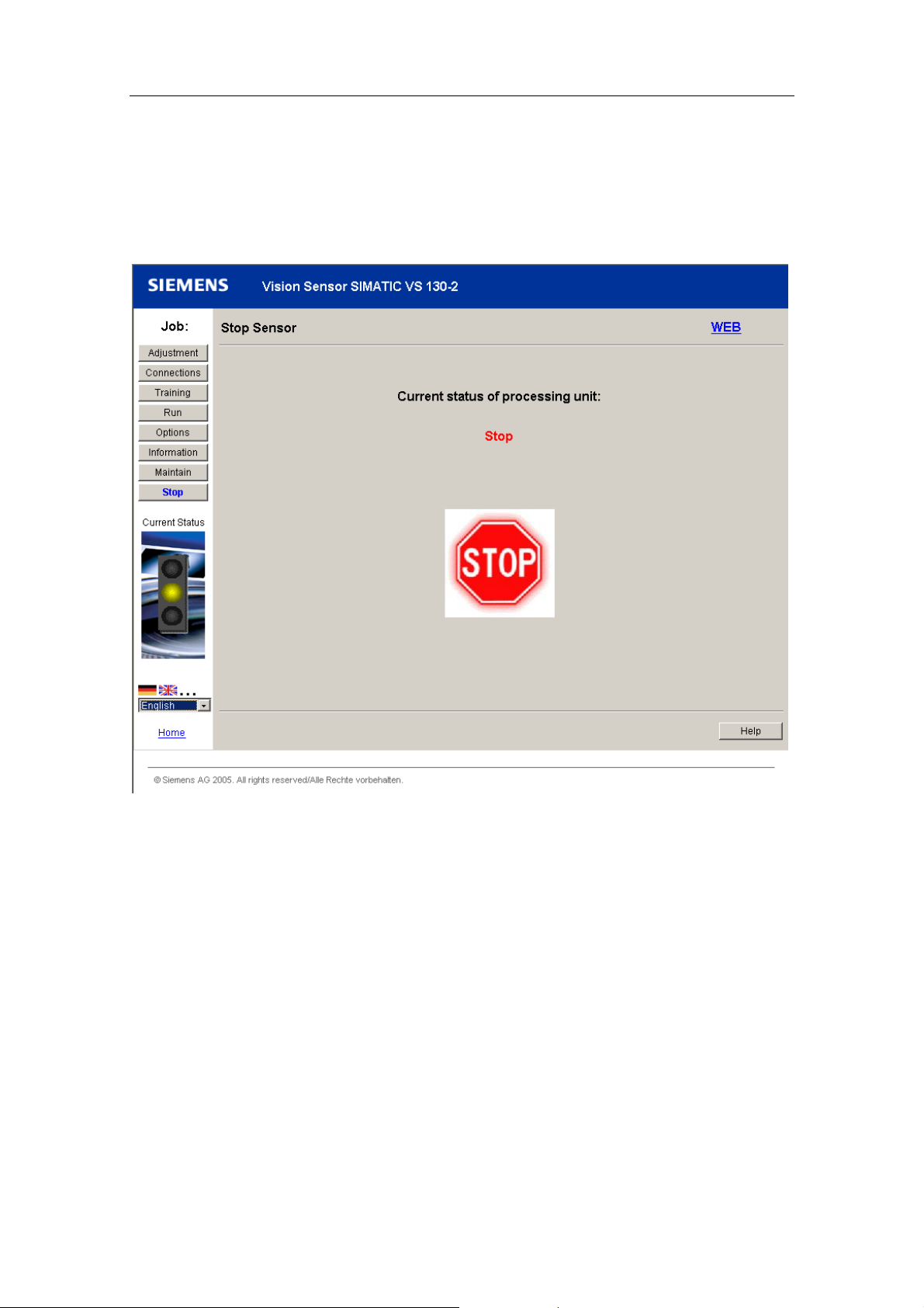
Operator Input
5.3.2 User interface of the VS 130-2/VS 130-2vcr
When you open the user interface, the page opens that corresponds to the current
operating state of the processing unit. If, for example, the processing unit is in Stop
mode, the page below opens:
Task
At the left-hand edge of the user interface, you will see the list of jobs in the form of
buttons. The appropriate job is activated depending on the previous operating state
of the processing unit. You can change between jobs using the buttons.
Traffic Light
Below the buttons, there is a traffic light with which you can see the operating state
of the processing unit at a glance. The traffic light can have the following states:
• Green: Processing mode with output of the result string
• Yellow: STOP including adjustment and training
• Red: Fault
Vision Sensor SIMATIC VS 130-2/VS 130-2vcr
A5E00475759-01
5-29
Page 74

Operator Input
Error Display
If an error occurs, the traffic light changes to red and the corresponding error
message, the meaning of the error and ways to eliminate the error are displayed. In
"Error output" in the online help, you will find a list with the meaning of the error
messages and instructions on how to remedy the problem.
Acknowledge the error by clicking the "Acknowledge" button. By acknowledging the
error, the user interface can change automatically to the current status of the
processing unit after the error has been eliminated.
Changing the language setting
At the bottom left, you will see a drop-down list box for language selection. You can
change the language setting for the entire user interface at any time.
WEB
At the upper right, you can see the currently logged-on user. By clicking on the
user name, you open the "Options Part 3/5: Security".
Help
At the bottom right, you will see a "Help" button with which you can call up online
help at any time. The relevant help text of the online help opens depending on the
currently open dialog.
Vision Sensor SIMATIC VS 130-2/VS 130-2vcr
5-30 A5E00475759-01
Page 75

Operator Input
5.3.3 Adjust Sensor
In this dialog, you make the settings for the correct adjustment of the sensor head.
Instructions
At the top left of the dialog, a static text is displayed providing brief instructions on
adjusting the sensor.
Current image
If "Recognition" is set, the status of image recognition is displayed:
• "Successfully finished" in blue text if the currently read code could be decoded
Only the images that the VS 130-2/VS130-2vc is attempting to process are
displayed. The images are displayed with a green border (indicates detected
code). The results box, the display of the minimum dot distance, and the boxes
with the five poorest quality characteristics are enabled. The last image
process and the results string remain displayed until the processing unit sends
the next results string or the recognition status changes to "Running".
• "Running" in red text if the currently read code could not be decoded at the first
attempt. In this case, VS 130-2/VS 130-2vcr makes further attempts to decode
(relearn). The images are displayed without a border. The results box, the
display of the minimum dot distance, the boxes with the five poorest quality
characteristics, and the corresponding labels are grayed out.
Vision Sensor SIMATIC VS 130-2/VS 130-2vcr
A5E00475759-01
5-31
Page 76

Operator Input
Read Settings
Here, you enter the parameters for image processing. The possible values and the
meaning of the parameters are described in the online help. You can open the
online help with the "Help" button (bottom right in the dialog).
With the "Freeze/Edit ROI" button or "Live Image" button, you can perform the
following actions:
• Change the region of interest
• Freezing the current image
• Displaying the live image.
Note
The labeling changes depending on what you activated and the labeling matches
the job you change to.
The region of interest is the area in which the VS 130-2/VS 130-2vcr reads
data such as data matrix codes. In the preview, this area is displayed with a
red box if "Speedup" "Use ROI" = On is activated in Part 5 of the "Options"
dialog or Exposure = Auto and Autom. Exposure >Use ROI = On is activated. If
you click on the Freeze/Edit ROI button, the image is frozen and you can adapt
the size of the region of interest in the preview.
You can freeze the current image if the region of interest is not used and no
live image is displayed.
Image display
Below the image display, there is a diskette symbol with which you can capture an
image with the VS 130-2/VS 130-2vcr and save the image in BMP format.
The following elements are displayed to the right of the image display:
• Green symbol on black background:
Sign of life for the connection between setup support and the sensor. The
green symbol is of variable size.
• Display of the dot size (not for PDF417 codes):
Display of the smallest and largest possible dots that can be decoded with the
existing equipment.
• "Full size" check box
A horizontal and vertical scrollbar is displayed at the lower edge of the image.
• "Current image":
The consecutive number of the currently displayed image is displayed.
Result
If a code was successfully decoded, the last read code or the modified result string
is displayed in the result field in the image preview. If the code could not be
decoded, this box is grayed out.
Vision Sensor SIMATIC VS 130-2/VS 130-2vcr
5-32 A5E00475759-01
Page 77

Operator Input
Quality / Grade / Value
If a code was correctly read (Recognition: "successfully finished"), the quality
characteristics that caused the most problems in reading the code with the current
setup are displayed here. By eliminating these problems, you can improve the read
reliability of the VS 130-2/VS 130-2vcr.
The quality grade has the range of values A, B, C, D, F, where A is the best and F
the poorest quality
The displayed characteristics are shown in the following colors:
• Petrol for grade A
• Cyan for grades B, C or D
• Red for grade F
You will find descriptions of the quality characteristics and the corresponding value
ranges in the online help that you can call with the "Help" button.
Vision Sensor SIMATIC VS 130-2/VS 130-2vcr
A5E00475759-01
5-33
Page 78
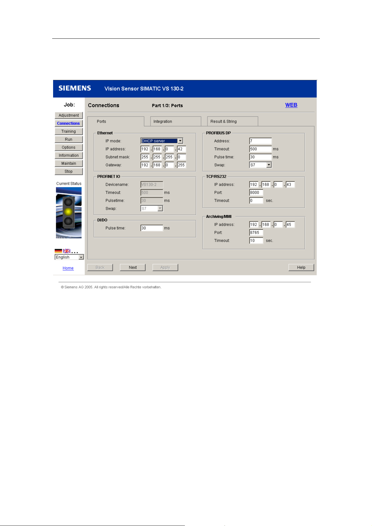
Operator Input
5.3.4 Connections
The Connections dialog is made up of the following three parts:
• Part 1/3: Ports
• Part 2/3: Integration
• Part 3/3: Result & String
Vision Sensor SIMATIC VS 130-2/VS 130-2vcr
5-34 A5E00475759-01
Page 79

Operator Input
Part 1/3: Ports
Here, you either specify or set parameters for the ports. Part 1/3: Ports includes the
following group fields:
• Ethernet
Here, you set the parameters for the Ethernet port.
• PROFINET IO
Here, you set the parameters for the PROFINET IO port. These input boxes
are enabled when you select "PROFINET mode" in the "IP Mode" drop-down
list box.
• DI/DO
Here, you set the switching duration of the digital outputs READ, MATCH,
N_OK.
• PROFIBUS DP
Here, you set the parameters for the PROFIBUS DP port. These input boxes
are enabled when you select "DHCP" or "Manual" or "DHCP Server" in the "IP
Mode" drop-down list box.
• TCP/RS-232
Here, you set the parameters for an Ethernet RS-232 converter connected to
the Ethernet port of the processing unit or for the PC/PG on which the TCP
server runs.
• Archiving/MMI
Here, you specify the address of a server to which you send images and / or
data records for diagnostics and a monitoring time after which connection
establishment is checked again to determine whether the connection exists
between the processing unit and server following a failed connection
establishment.
Note
You will find a detailed description of the parameters the possible values in the
online help that you can call with the "Help" button.
With the "Next" button, you change to the next part of the "Connections" dialog.
The "Apply" button is enabled only when you have changed settings. When you
click on one of these buttons, all the parameters of the current dialog are saved.
The dialog remains open.
Vision Sensor SIMATIC VS 130-2/VS 130-2vcr
A5E00475759-01
5-35
Page 80

Operator Input
Part 2/3: Integration
Here, you specify the path over which signals are sent to the processing unit and
over which path the result string is output.
You will find a detailed description of the possible settings in the online help that
you can call with the "Help" button.
Note
You cannot set every combination of settings for String, Result and Control. If a
combination is not permitted, (for example Text = PROFIBUS DP and Control =
DI/DO), an error message to this effect is displayed in the lower part of the dialog.
Part 3/3: Result & String
Here, you specify whether and how result string or filtered text sections, quality
values, positions etc. are output over the RS-232 port of an Ethernet RS-232
converter or over DP or to a TCP server. You can also specify which text appears
on the display of the processing unit if an error occurs.
In the "Result String" group box, you specify whether all characters of the read
code are output or only a substring (according to the filter settings of ID or
Position). With the "Format string" input box, you can also specify the content and
the format of the string to be output. How to make these settings is described in the
online help that you can call with the "Help" button.
In the "Error messages" group box, you specify which text is output on the display
of the processing unit and over Ethernet or DP if the relevant error occurs. You can
select any string to be output by entering the required text in the relevant input box.
Vision Sensor SIMATIC VS 130-2/VS 130-2vcr
5-36 A5E00475759-01
Page 81

Operator Input
5.3.5 Train
If you want to compare read codes with each other or use the
VS 130-2/VS 130-2vcr for quality control, you can train codes that can be used for
a comparison. The last transferred image is displayed in the preview. With the
diskette symbol, you can save the current image in BMP format.
"Use this image" Option Button
If this option is selected, the currently displayed image will be used for code
training. The preview only shows the image last acquired when the check box was
activated.
If this option is not selected, the next triggered image will be used for code training
after you click the "Start Training" button.
Vision Sensor SIMATIC VS 130-2/VS 130-2vcr
A5E00475759-01
5-37
Page 82

Operator Input
"Start Training" Button
Clicking this button starts the training of the code. After successful training, you
move on to Part 2 of the dialog "Train Code".
The following is displayed in this dialog:
• The image of the acquired code
• Below this, the result in the form of a string and
• The exposure time, brightness and quality of the code (quality grade from A =
To save the code, enter a number between 1 and 14 in "Code number" and click
"Save". Under "Saved codes", you can see which code numbers are already being
used. You can overwrite existing codes by entering the corresponding code
number.
best quality to F = worst quality).
Vision Sensor SIMATIC VS 130-2/VS 130-2vcr
5-38 A5E00475759-01
Page 83

Operator Input
5.3.6 Evaluating
In this dialog box, you can start the processing mode. The codes are read and, if
applicable, checked to find out whether they match a trained code or whether they
contain one or more predefined strings. Depending on whether or not you use
multicode (see Options, Part 5 : Extras), you can use individual codes (if Multicode
> Use = Off) or code sets (if Multicode > Use = On).
Select code / Select code set
Here, you enter the number of a previously trained code or code set that you want
to compare with a current code. The following values are available here:
• The numbers of all codes / code sets that have already been trained
• "Auto", if you set the value "Read" as job in the "Job" drop-down list box in
"Options" in Part 1/5: Decoder.
Vision Sensor SIMATIC VS 130-2/VS 130-2vcr
A5E00475759-01
5-39
Page 84

Operator Input
5.3.7 Options
The "Options" dialog is made up of the following five parts:
• Part 1/5: Decoder
• Part 2/5: Lighting & Acquisition.
• Part 3/5: Security
• Part 4/5: Diagn. & Monitoring
• Part 5/5: Extras
Part 1/5: Decoder
In the "Decoder" group box, you specify the job you want to perform with the
VS 130-2/VS 130-2vcr: Read, Match or Verify. With the match function, the entire
code or parts of it is compared with a trained code, with the Verify function, the
quality values of the currently read code are related to the quality values of a
trained code. You also specify the reading speed and set the maximum processing
time with the cycle time limit.
Vision Sensor SIMATIC VS 130-2/VS 130-2vcr
5-40 A5E00475759-01
Page 85

Operator Input
Part 2/5: Lighting & Acquisition.
In the "Lighting" group box, you set the type of lamp you are using.
In the "Acquisition" group box, you enter the type of lighting control and set the
exposure time, the brightness, the light source and, if necessary, the shutter speed
offset. You will find further information in the online help that you can call with the
"Help" button.
Part 3/5: Security
In this tab, the administrator must also specify which user is permitted to execute
which tasks and can, when necessary, change the passwords of the users.
Users can also log on under their names with the appropriate password. Below the
"User" table, you can see the role for which you are currently logged on. In the "Log
on" group box, you can change this role by selecting a role from the "User" dropdown list box and logging on with the correct password.
Part 4/5: Diagn. & Monitoring
In this tab, you specify the information to be stored for diagnostic purposes.
In "Image" in the "Logging" group box, you specify which pictures will be stored and
in which form on the processing unit. In "Report", you specify the form in which
diagnostic events will be stored on the processing unit.
In the "Time base" group box, you specify whether the time stamp of the diagnostic
events is provided by the PC or by an SNTP server of the network. If you select
SNTP as the source, you must also specify the IP address of the server.
In the "Monitoring" group box, you specify whether a live image is displayed in
processing mode.
In the "Persistence" group box, you specify which diagnostic information you want
to store permanently on the EPROM.
If the "Save NOK image" check box is enabled, the image of the next NOK signal is
stored. If an image is already stored, it is overwritten when this function is selected.
If the "Save diag. entries" check box is enabled, the number of diagnostic entries
you specify in the input box will be entered in the EPROM. Existing entries are
deleted when you switch over to On. If the diagnostic buffer in the EPROM reaches
the number of permanently storable diagnostic data records, no further entries are
made.
Vision Sensor SIMATIC VS 130-2/VS 130-2vcr
A5E00475759-01
5-41
Page 86

Operator Input
Part 5/5: Extras (only for VS 130-2)
Lighting & Acquisition.
The multilight function is only possible if you have connected a multiplexer and
more than one lamp. Enable the "Multilight" function in the "Lighting and
Acquisition" group box to be able to select the lamp used for the image capture
from the setup support. When using the multilight function, only one of the lamps
you select from the drop-down list box is ever active. In this mode, the result bits
cannot be output over the DI/DO interface.
Under "Autom. Exposure", you can decide whether the entire image area or a
smaller area (region of interest) is used to calculate the optimum exposure
parameters. You can change this region of interest by changing to the "Adjustment"
dialog and moving or scaling (only possible when "Freeze/ROI" mode is activated)
the red frame in the preview window.
With "Use shuttersp. offset", you decide whether or not the automatically calculated
exposure time is corrected by the value of the shutter speed offset (Part 2 of the
"Options" dialog).
Acceleration
In the "Speedup" group box, you make the settings to speed up image processing.
This is effective only when Speed = low (see Part 1 of the "Options" dialog).
You have the following options:
• Use ROI": The region of interest set in the "Adjustment" dialog is used in the
image processing.
• "Decoder order": Here, you specify the order of the code types in which the
processing unit attempts to decode a code when training, when reading
(without prior training) and in adjustment mode.
• With data matrix codes, there are the speedup parameters Polarity, Dimension
and View that can each have the value "trained" or "dynamic":
- Polarity:
When Polarity = "trained" is set, the processing unit does not decode the
read code if bright and dark dots are swapped over compared with the
trained code. When Polarity = "dynamic" is set, the processing unit
decodes the read code even if bright and dark dots are swapped over
compared with the trained code.
- Dimension:
If Dimension = "trained", the processing unit does not decode the read
code if the number of dots is different from the trained code. If Dimension =
"dynamic", the processing unit decodes the read code even if the number
of dots is different from the trained code.
- View:
If View = "trained" is set , the processing unit does not decode the read
code if it is mirrored compared with the trained code. If View = "dynamic" is
set , the processing unit decodes the read code even if it is mirrored
compared with the trained code.
Vision Sensor SIMATIC VS 130-2/VS 130-2vcr
5-42 A5E00475759-01
Page 87

Operator Input
Multicode
The "Multicode" mode allows you to capture and evaluate several images at the
same time with one trigger. To use this function, choose a code set number (1-14)
in the "Code set" drop-down list box and select the codes to be included in the
code set in "Contains codes". Based on the code set, the processing unit obtains
the settings with which the images will be captured at the first trigger and the
trained codes with which they will be compared.
At each further trigger, the processing unit starts at the image of the code that was
last read successfully. If no code can be read, the current decoding order is
maintained.
Note
If a code set contains a code number under which no code was previously trained,
you cannot use this code set for evaluation. With the "Info" job, you can see the
code number under which trained codes are stored in Part 2/4: Code(s).
Vision Sensor SIMATIC VS 130-2/VS 130-2vcr
A5E00475759-01
5-43
Page 88

Operator Input
5.3.8 Info
The Info dialog is made up of the following five parts:
• Part 1/5: Statistics.
• Part 2/5: Code(s)
• Part 3/5: Diagnostics
• Part 4/5: Analysis
• Part 5/5: Device Info
Vision Sensor SIMATIC VS 130-2/VS 130-2vcr
5-44 A5E00475759-01
Page 89

Operator Input
Part 1/5: Statistics
In this part of the dialog, you can see statistical values relating to the reading of the
codes and the read quality. You will find a description of the displayed information
in the online help that you can call with the "Help" button.
If you have disabled the Multicode mode (see Part 5 of the Options dialog), you
enter information here out the currently used code.
If the Multicode mode is enabled, a drop-down list box is displayed. In the dropdown list box, you can decide whether the statistics of the entire code set or the
statistics of a specific code is displayed.
If you simply want the statistics of the OK reads of a certain code, select the code
number of the relevant set from the drop-down list box. With this setting, the "*"
symbol is displayed at several positions.
You can clear the statistics with the "Reset statistics" button if you have
management permissions (see Options Part 3/4: Security). The statistics are reset
automatically when you change the code.
Information Part 2/5: Code(s)
In this part of the dialog, you see the exposure and properties of a trained code or
the settings of code to be read along with the image and the result string.
In "Select code", you can specify the number of the trained code whose properties
you want to display.
In the "Training Information" group box, the shutter speed, if applicable the shutter
speed offset, and the brightness with which the image was acquired during training
of the code are displayed.
The "Quality" group box displays all the quality characteristics of the trained code.
The quality is specified as a quality grade (A = best to F = worst quality) and
specified in an absolute value.
By clicking on the "Runtime >" button, you open the page displaying the settings of
a code to be read.
Vision Sensor SIMATIC VS 130-2/VS 130-2vcr
A5E00475759-01
5-45
Page 90

Operator Input
Information Part 3/5: Diagnostics
Images
In "Images", you can see the number of images currently in the image buffer.
If you click the "Reset" button, you delete all images in the image buffer.
Clicking the "Open" button opens a web page with all the images of the image
buffer. If you click on one of these images, the image is magnified.
Clicking the "Save" button opens a web page with all the images of the image
buffer. You can save this Web page in various formats on your computer.
Data record
The "Data records" group box displays the number of diagnostic events currently in
the events buffer.
With the check box under "Content", you specify which information you want to
display about the diagnostic events in the buffer:
• Error: Information on the occurrence and acknowledgment (manual or
automatic) of errors
• Decode: Evaluation result
• Image: Information on the image capture, for example shutter speed,
brightness
• States: Mode change (change to RUN, ADJUST, Self-test, etc.)
• Controller: Change of control of the processing unit (control by keyboard,
WEB, CPU)
• Diagnostics: Changes that affect diagnostics, for example changing the
diagnostic options, fetching a time stamp from an SNTP server
By clicking the "Reset" button, you delete all the entries in the event buffer
including the entries relating to temporary PROFIBUS DP or PROFINET IO errors.
If you click on the "Save as CSV" button, a dialog opens in which you can store the
events currently selected under "Content" as a csv file.
Clicking the "Open&Save" button opens a web page with all the events of the
events buffer. You can save this Web page in various formats on your computer.
Persistent data records
Clicking the "Open & Save" button opens a web page with all the diagnostic entries
saved permanently on the processing unit. You can save this Web page on your
computer.
If you click on the "Save as CSV" button, a dialog opens in which you can save the
diagnostic events permanently stored on the processing unit as a csv file.
Vision Sensor SIMATIC VS 130-2/VS 130-2vcr
5-46 A5E00475759-01
Page 91

Operator Input
Information Part 4/5: Analysis
If the processing unit is in STOP mode, in this part of the dialog for the VS 130-2
you can display the last processed image, a persistently stored image or an image
in the diagnostic buffer along with its additional information.
You can also start an evaluation attempt for the displayed image. If processing is
successful, the detected code type and the result string are displayed. With a data
matrix code, you obtain further information on the total number of dots, the correct
and corrected dots and on the surrounding rectangles of objects detected in the
image.
Information Part 5/5: Device Info
This part of the dialog provides you with information on the processing unit, the
firmware, the sensor and the software.
Vision Sensor SIMATIC VS 130-2/VS 130-2vcr
A5E00475759-01
5-47
Page 92

Operator Input
5.3.9 Maintain
Maintain code(s)
In this group box, you can deleted trained codes by selecting the relevant code
number from the drop-down list box and clicking on "Delete".
When you click the "Reset" button next to "Factory settings:" you reset all
parameters to their default values. The trained codes are also deleted.
Maintain processing unit
The "Save/Restore" button opens a Web page where you can save trained codes
and parameter assignments or load them on the processing unit again.
Note
When you load a code on the processing unit, the parameters saved with the code
are also loaded and therefore valid.
The "Firmware update" button opens a Web page where you can update the
firmware.
Note
If you control the VS 130-2/VS 130-2vcr from an automation system, make sure
that the DISA bit is not set during the firmware update. This prevents a
programmable controller from changing the processing unit to RUN.
5.3.10 Stop
When you call this dialog, you change the processing unit to STOP mode.
Vision Sensor SIMATIC VS 130-2/VS 130-2vcr
5-48 A5E00475759-01
Page 93

Operator Input
5.4 Operator Control over Personal Digital Assistant (PDA)
5.4.1 Prerequisites
To be able to operate the Vision Sensor SIMATIC VS 130-2/VS 130-2vcr over a
PDA, the following requirements must be met:
• WLAN-compliant PDA with the Windows Mobile 2003 operating system, for
example, Fujitsu-Siemens Pocket LOOX 610
• Macromedia Flash Player 6 is installed on the PDA
• Established connection between the PDA and the processing unit over a
WLAN router
How you establish this connection is described in Establishing a connection
between PDA and processing unit.
We recommend a work memory of 128 Mbytes or larger.
5.4.2 Establishing a Connection between PDA and Processing Unit
To establish a connection between PDA and processing unit, follow the steps
outlined below:
1. Install and configure your WLAN router.
You require an Ethernet connection between your PC and the router (for example,
Siemens Gigaset SE505 dsl/cable). Configure the router as DHCP server and, if
necessary, change its IP address. To set the configuration, you work in the user
interface of the router over a JAVA-compliant browser by entering the preset IP
address.
2. Configure the processing unit as a DHCP client.
You do this in the Connect> Ports> Ethernet> IP Mode menu by setting "DHCP".
3. Connect the WLAN router to the processing unit over an Ethernet cable and turn
the processing unit on. Then check the IP address assigned to the processing unit
by the router in the Connect> Ports> Ethernet> IP Address menu.
4. Enable Wireless LAN on your PDA.
Depending on the PDA, you will either have to install a wireless network adapter
or simply enable the Wireless LAN integrated on the PDA.
Vision Sensor SIMATIC VS 130-2/VS 130-2vcr
A5E00475759-01
5-49
Page 94

Operator Input
5.4.3 Starting or stopping setup support from the PDA
It is assumed that the connection between PDA and processing unit is established.
Proceed as follows:
1. Start the Internet Explorer on the PDA, enter the IP address in the "Address" input
box and then press "Enter".
The start page of the setup support appears.
2. Click on "Live image for PDA".
The user interface of the PDA for the VS 130-2/VS 130-2vcr appears.
Note
If you have started the user interface of the PDA, you can only run the setup
support from a PC/PG in read-only mode.
If you want to terminate the connection to the processing unit, turn off the PDA.
Closing the Internet Explorer does not terminate the connection.
5.4.4 User interface of the PDA
Overview
The user interface consists of the following elements:
• Live image
• Text display row
• Operator input row with the mode button, the "Trg" trigger button (VS 130-2vcr
only) and the code selection.
Note
If there is a connection between the Web browser of a PC and the processing unit
or the VS 130-2/VS 130-2vcr is being controlled by an automation system, all
buttons are disabled and "(Read Only Mode)" is displayed in the text display row.
As long as no physical connection can be established to the processing unit,
"Connecting…" is displayed.
The labeling of the buttons and their function depend on the current status of the
VS 130-2/VS 130-2vcr. This also applies to the strings of the text display row. This
is explained in detail below.
Vision Sensor SIMATIC VS 130-2/VS 130-2vcr
5-50 A5E00475759-01
Page 95

Operator Input
Mode button
Current status of the
Vision Sensor
RUN -> Adjust Changes to the adjustment mode
Adjust -> Run Changes to the processing mode
STOP -> Adjust Changes to the adjustment mode
Train -> Adjust Changes to the adjustment mode
Error Acknowledge error Acknowledges the error and exits the error
Label of the Mode
button
Meaning
status
"Trg" trigger button
This button exists only with the VS 130-2vcr. It is enabled only when the
processing unit is in RUN.
If you click on this button, you simulate an external trigger signal.
Code selection
Using the "<" and ">" buttons, select a trained code with the settings you want to
use for the image processing.
Code selection is enabled only in the adjustment mode.
Text display row
Current status of the
Vision Sensor
RUN "Run:" + result string or "ReadErr (Nothing found)"
Adjust "Adjust: live" or "Adjust: read"
STOP "Stop"
Train "Stop"
Error "Error:" + Error number
Content of the text display row
Vision Sensor SIMATIC VS 130-2/VS 130-2vcr
A5E00475759-01
5-51
Page 96

Operator Input
The text display in the Adjustment status of the Vision Sensor has the following
meaning:
• "Adjust: live": No code could be decoded yet (corresponds to "Recognition:
• "Adjust: read": No currently read code could be decoded (corresponds to
• If an error occurs, an error number is output here. You will find the meaning in
running" on the setup support).
"Recognition: successfully finished" on the setup support).
the following table.
No. Description Possible Remedies
0 The connected sensor type is
not supported.
1 No sensor connected. Connect the sensor to the processing unit
2 DISA changed at an invalid time
(during training)
3 During training, the correct
sequence of applied signals is
not kept to.
4 The code could not be recreated. Run the training again.
5 The send buffer is full because
the data cannot be sent in an
adequately short time,
6 The send buffer is full because
the data cannot be sent in an
adequately short time or the
server does not confirm receipt
of the data in good time
7 The transfer of the last read
result is not yet completed, the
next read result is, however,
already available, or the DP
master or IO controller does not
reply within the handshake
monitoring time (parameter
Connect >Ports >DP >Timeout
on processing unit or within the
time limit parameter in
PROFIBUS DP in Part 1/3: Ports
of the Connections dialog in the
setup support, parameter
Connect >Ports >PNIO
>Timeout on processing unit or
within the time limit parameter in
PROFINET IO in Part 1/3: Ports
in the "Connections" dialog in the
setup support).
8 The DP settings are not correct Correct the DP settings.
9 No code was found in the image
during training.
Connect a sensor supported by
VS 130-2/VS 130-2vcr.
correctly.
Check the sequence of applied signals. Start the
training again.
Check the sequence of applied signals. Start the
training again.
Reduce the trigger frequency or process the
results more quickly on the server. A high load on
the network to which the processing unit is
connected can also block the transfer of the data.
If necessary, check the network connection.
Reduce the trigger frequency or reduce the
amount of diagnostic data to be archived. Process
the results on the server faster. A high load on the
network to which the processing unit is connected
can also block the transfer of the data. If
necessary, check the network connection.
Reduce the trigger frequency or process the
results more quickly.
If necessary, change the transmission rate for the
DP configuration or the update time for the
PROFINET configuration.
Position the code within the image or improve the
image quality.
Vision Sensor SIMATIC VS 130-2/VS 130-2vcr
5-52 A5E00475759-01
Page 97

Operator Input
No. Description Possible Remedies
10 The trained code cannot be
processed with the match
settings (for example
ID/separator not found)
11 The code found during training
does not comply with the ECC
200 standard.
12 Error in PROFIBUS DP
communication.
13 Connection error in
communication over a TCP
connection or when using an
Ethernet RS-232 converter:
There is no TCP connection or
the data transfer cannot be
completed within the set time
limit.
14 Error in communication over the
archiving connection: There is no
TCP connection, the server does
not respond within the set time
limit or violates the archiving
protocol.
15 The IR lighting unit is
overloaded.
Below you will see the maximum
trigger frequency fT for the
selected shutter speeds TB:
• TB = 500 µs: fT = 60 Hz
• TB = 1000 µs: fT = 40 Hz
• TB = 2000 µs: fT = 20 Hz
• TB = 3000 µs: fT = 13 Hz
• TB = 4000 µs: fT = 10 Hz
• TB = 5000 µs: fT = 8 Hz
• TB = 6000 µs: fT = 7 Hz
• TB = 7000 µs: fT = 6 Hz
• TB = 8000 µs: fT = 5 Hz
• TB = 9000 µs: fT = 4.5 Hz
• TB = 10000 µs: fT = 4 Hz
Note: Trigger frequencies
> 33 Hz are not practicable.
16 You are attempting to train code
number 15 over digital I/O or
PROFIBUS DP or PROFINET
IO. This is, however, are
reserved for automatic learning.
18 An error occurred in PROFINET
I/O communication
19 An error occurred when saving
to the read-only memory.
Adapt the match settings, or train a suitable code.
Use a code that complies with the standard.
Make sure that the parameters for communication
over PROFIBUS DP and the communication
partners are correctly configured and active. Check
the connection to the DP master.
Make sure that the connected TCP server or
Ethernet RS-232 converter is correctly configured
and operational.
Depending on the connected Ethernet RS-232
converter, it can take up to 20 s before changes to
the RS-232 settings or parameter changes for the
trigger source or the output of the result string to
"TCP/RS232" take effect. During this time, the first
trigger of a processing cycle should not occur nor
should that be a change to RUN.
Check the connection to the server.
Make sure that the data is processed by the server
in an adequately short time and that the protocol is
maintained.
Reduce the trigger frequency or reduce the shutter
speed.
Select a code number between 1 and 14.
Make sure that the parameters for communication
over PROFINET I/O and the communication
partners are correctly configured and active. Check
the connection to the I/O controller.
Contact Customer Support if this error occurs
often.
Vision Sensor SIMATIC VS 130-2/VS 130-2vcr
A5E00475759-01
5-53
Page 98

Operator Input
5.4.5 Known PDA problems
Two known PDA problems are described below:
• The cache is full after some time.
The Web browsers of some PDAs have the unwanted tendency to store more
and more data in the cache as time goes on without releasing the memory
again. As a result, the Web browser no longer runs.
• If you click the "Close" button, the Web browser is removed from the screen of
some PDAs but continues to run in the background. In conjunction with the first
problem explained above, this soon leads to memory overflow.
You can counter these problems with the measures described below. Follow the
order of steps below and following each step, check whether the memory used has
been released again. If it is released, the remaining steps are unnecessary.
1. Exit the Web browser as follows: Start > Settings > "System" tab > Memory >
"Running Programs" tab, select "Internet Explorer" and click on the "Stop".
2. Internet Explorer: Tools > Options… > "Memory" tab, click on the "Delete Files"
button.
3. Turn the PDA off.
4. Run a soft reset on the PDA (usually by pressing a hidden button with a pen or
similar).
5. Run a hard reset on the PDA.
Vision Sensor SIMATIC VS 130-2/VS 130-2vcr
5-54 A5E00475759-01
Page 99

6 Process Interface
6.1 Introduction
As an alternative to controlling from the operator panel or using the setup support,
you can also control SIMATIC VS 130-2/VS 130-2vcr from a programmable
controller. This makes it possible to train and work almost automatically.
Control over PROFIBUS DP and PROFINET IO is only possible with the VS 130-2,
control over the I/O interface "DI/DO", on the other hand, is possible with VS 130-2
and VS 130-2vcr.
Note
The automatic training and changing of codes by a programmable controller is only
possible with active setup support when in the "Options part 3/4: Security", the
check box "Take control" is not enabled for the current user.
Vision Sensor SIMATIC VS 130-2/VS 130-2vcr
A5E00475759-01
6-1
Page 100

Process Interface
6.2 Integrating the DP slave VS 130-2 in HW Config
The supplied device master data file SIEM8111.GSD contains the PROFIBUS
properties of the VS 130-2 DP standard slave. If you are using a STEP 7 version
earlier than V5.3 SP1, the Vision Sensor VS 130-2 is not yet in the modules
catalog in HW Config. In this case, you must add it to the catalog with Options >
Install GSD... . Remember that the corresponding bitmap file VS1X0__N.DIB must
be in the same folder as the GSD file.
You can download both files from the Internet at
http://support.automation.siemens.com/WW/llisapi.dll?func=cslib.csinfo&lang=de&o
bjID=10807086&subtype=133100.
The Vision Sensor VS 130-2 then appears in the modules catalog under
PROFIBUS DP \ Additional Field Devices \ General \ Machine Vision
(see screenshot below).
In the configuration example above, the control byte of the VS 130-2 was set to
output address 0 and the status byte of the VS 130-2 was set to input address 0 of
the CPU (DP master, slot 1). If these addresses are in the process image of OB1
(process image partition "OB1 PI"), you can work here in OB1 with process image
access (for example "A I0.6" or "S Q0.1"). If this is not the case, you must work
with direct I/O access (for example "L PIB 0").
In the configuration example above, the start of the 16 word long consistent
communication area of the Vision Sensor VS 130-2 was set to input address 1 and
output address 1 (slot 2). If these addresses are in the process image of OB1
(process image partition "OB1 PI"), you can work here in OB1 with process image
access (e.g. "L EW 2", "T AB 1"), without violating the consistency (This is only
valid for CPUs which transfer consistent user data per process image, see the note
below). If, on the other hand, these addresses are not in the process image of
OB1, you must access the communication area of the VS 130-2 using SFCs 14
"DPRD_DAT" and 15 "DPWR_DAT" to ensure consistency.
Vision Sensor SIMATIC VS 130-2/VS 130-2vcr
6-2 A5E00475759-01
 Loading...