

Page 1

_
_
_
_
_
_
_
_
_
_
SIMATIC SIMATIC SM331; AI 8x12 Bit Getting Started part 1: 4 -20mA
SIMATIC
Preface
_____________
Requirements
_____________
Introduction
_____________
1
2
3
SM331; AI 8x12 Bit Getting Started
part 1: 4 -20mA
Getting Started
Mechanical setup of the
example station
_____________
Electrical connection
_____________
Configuration of the
SIMATIC Manager
_____________
Testing the user program
_____________
Diagnostic interrupt
_____________
Hardware interrupt
_____________
Appendix
_____________
4
5
6
7
8
9
A
11/2006
A5E00253410-02
Page 2

Safety Guidelines
This manual contains notices you have to observe in order to ensure your personal safety, as well as to prevent
damage to property. The notices referring to your personal safety are highlighted in the manual by a safety alert
symbol, notices referring only to property damage have no safety alert symbol. These notices shown below are
graded according to the degree of danger.
Danger
indicates that death or severe personal injury will result if proper precautions are not taken.
Warning
indicates that death or severe personal injury may result if proper precautions are not taken.
Caution
with a safety alert symbol, indicates that minor personal injury can result if proper precautions are not taken.
Caution
without a safety alert symbol, indicates that property damage can result if proper precautions are not taken.
Notice
indicates that an unintended result or situation can occur if the corresponding information is not taken into
account.
If more than one degree of danger is present, the warning notice representing the highest degree of danger will
be used. A notice warning of injury to persons with a safety alert symbol may also include a warning relating to
property damage.
Qualified Personnel
The device/system may only be set up and used in conjunction with this documentation. Commissioning and
operation of a device/system may only be performed by qualified personnel. Within the context of the safety notes
in this documentation qualified persons are defined as persons who are authorized to commission, ground and
label devices, systems and circuits in accordance with established safety practices and standards.
Prescribed Usage
Note the following:
Warning
This device may only be used for the applications described in the catalog or the technical description and only in
connection with devices or components from other manufacturers which have been approved or recommended by
Siemens. Correct, reliable operation of the product requires proper transport, storage, positioning and assembly
as well as careful operation and maintenance.
Trademarks
All names identified by ® are registered trademarks of the Siemens AG. The remaining trademarks in this
publication may be trademarks whose use by third parties for their own purposes could violate the rights of the
owner.
Disclaimer of Liability
We have reviewed the contents of this publication to ensure consistency with the hardware and software
described. Since variance cannot be precluded entirely, we cannot guarantee full consistency. However, the
information in this publication is reviewed regularly and any necessary corrections are included in subsequent
editions.
Siemens AG
Automation and Drives
Postfach 48 48
90437 NÜRNBERG
GERMANY
Order No.: A5E00253410-02
11/2006
Copyright © Siemens AG 2006.
Technical data subject to change
Page 3

Table of contents
1 Preface ................................................................................................................................................... 1-1
1.1 General ...................................................................................................................................... 1-1
2 Requirements ......................................................................................................................................... 2-1
2.1 Basics......................................................................................................................................... 2-1
3 Introduction............................................................................................................................................. 3-1
3.1 Example of an application.......................................................................................................... 3-1
4 Mechanical setup of the example station................................................................................................ 4-1
4.1 Mounting the example station.................................................................................................... 4-1
4.2 Mounting of analog module components................................................................................... 4-3
4.2.1 General ...................................................................................................................................... 4-3
4.2.2 Components of the SM331 ........................................................................................................ 4-4
4.2.3 Features of the analog modules ................................................................................................ 4-5
4.2.4 Measuring range modules ......................................................................................................... 4-6
4.2.5 Mounting the SM331 module..................................................................................................... 4-8
5 Electrical connection............................................................................................................................... 5-1
5.1 Overview .................................................................................................................................... 5-1
5.2 Wiring the power supply module and the CPU.......................................................................... 5-2
5.3 Wiring of the analog module ...................................................................................................... 5-4
5.3.1 Requirement............................................................................................................................... 5-4
5.3.2 Current transducer wiring - principle.......................................................................................... 5-4
5.3.3 Wiring of the analog module ...................................................................................................... 5-5
5.3.4 Test ............................................................................................................................................ 5-8
6 Configuration of the SIMATIC Manager.................................................................................................. 6-1
6.1 Creating a new STEP7 project................................................................................................... 6-1
6.1.1 Creating a new project ............................................................................................................... 6-1
6.1.2 CPU selection ............................................................................................................................ 6-3
6.1.3 Defining the basic user program................................................................................................ 6-4
6.1.4 Assigning the project name........................................................................................................ 6-5
6.1.5 Result S7 project is created ....................................................................................................... 6-6
6.2 Hardware configuration.............................................................................................................. 6-7
6.2.1 Creating the hardware configuration.......................................................................................... 6-7
6.2.2 Adding SIMATIC components.................................................................................................... 6-8
6.2.3 Configuring the analog module................................................................................................ 6-10
6.2.4 Test .......................................................................................................................................... 6-13
6.3 STEP 7 user program .............................................................................................................. 6-17
6.3.1 Tasks of the user program ....................................................................................................... 6-17
6.3.2 Creating a user program.......................................................................................................... 6-18
SM331; AI 8x12 Bit Getting Started part 1: 4 -20mA
Getting Started, 11/2006, A5E00253410-02
iii
Page 4

Table of contents
7 Testing the user program........................................................................................................................ 7-1
7.1 Downloading system data and user program ............................................................................ 7-1
7.2 Visualization of the sensor values.............................................................................................. 7-3
7.3 Analog value representation ...................................................................................................... 7-8
8 Diagnostic interrupt................................................................................................................................. 8-1
8.1 Reading diagnostic information from a PG ................................................................................ 8-1
8.2 General diagnostics ................................................................................................................... 8-3
8.3 Channel dependent diagnostic interrupts .................................................................................. 8-4
8.3.1 There are five channel dependent diagnostic interrupts............................................................ 8-4
8.3.2 Configuration / programming error............................................................................................. 8-4
8.3.3 Common mode error.................................................................................................................. 8-4
8.3.4 Wire break.................................................................................................................................. 8-5
8.3.5 Underflow ................................................................................................................................... 8-5
8.3.6 Overflow ..................................................................................................................................... 8-6
9 Hardware interrupt.................................................................................................................................. 9-1
9.1 Hardware interrupt ..................................................................................................................... 9-1
A Appendix.................................................................................................................................................A-1
A.1 Source of the user program .......................................................................................................A-1
Index................................................................................................................................................ Index-1
SM331; AI 8x12 Bit Getting Started part 1: 4 -20mA
iv Getting Started, 11/2006, A5E00253410-02
Page 5

Preface
1.1 General
Purpose of the Getting Started
The Getting Started gives you a complete overview of the commissioning of the analog
module SM331. It assists you in the installation and configuration of the hardware of a 420mA sensor and the configuration with SIMATIC S7 Manager.
The intended readership of Getting Started is a novice with only basic experience in
configuration, commissioning and servicing of automation systems.
What to expect
The procedures, from mounting the module to storing analog values in the STEP7 user
program, are explained step-by-step and in detail based on an example. In the following
sections you will be introduced to:
● Problem analysis
● Mechanical setup of the example station
1
● Electrical connection of the example station
● Configure hardware with SIMATIC Manager
● Creating a small user program with STEP7 which stores the read analog values in a data
block
● Triggering and interpreting diagnostic and hardware interrupts
SM331; AI 8x12 Bit Getting Started part 1: 4 -20mA
Getting Started, 11/2006, A5E00253410-02
1-1
Page 6

Preface
1.1 General
SM331; AI 8x12 Bit Getting Started part 1: 4 -20mA
1-2 Getting Started, 11/2006, A5E00253410-02
Page 7

Requirements
2.1 Basics
Basic Knowledge Required
No special knowledge of the field of automation technology is required in order to understand
the Getting Started guide. As the configuration of the analog module is done with the
software STEP7, proficiency in STEP7 would be advantageous.
Further information on STEP7 can be found in the electronic manuals that are supplied with
STEP7.
You will also need to know how to use computers or PC-like equipment (such as
programming devices) under Windows 95/98/2000/NT or XP.
Required hardware and software
The scope of delivery of the analog module consists of 2 parts:
● The module itself
● A front connector, which enables you to conveniently connect the power supply and the
data cables.
2
Analog module components
Quantity Article Order number
1 SM 331, Electrically ISOLATED 8 AI, ALARM DIAGNOSTICS 6ES7331-7KF02-0AB0
1 20-pin FRONT CONNECTOR with spring contacts 6ES7392-1BJ00-0AA0
The general SIMATIC components required for the example are as follows:
SIMATIC components of the example station
Quantity Article Order number
1 PS 307 Power Supply AC 120/230V, DC 24V, 5A 6ES7307-1EA00-0AA0
1 CPU 315-2 DP 6ES7315-2AG10-0AB0
1 MICRO MEMORY CARD, NFLASH, 4 MB 6ES7953-8LM00-0AA0
1 SIMATIC S7-300, RAIL L=530MM 6ES7390-1AF30-0AA0
1 Programming device (PD) with MPI interface and MPI cable
PC with corresponding interface card
SM331; AI 8x12 Bit Getting Started part 1: 4 -20mA
Getting Started, 11/2006, A5E00253410-02
depending on the
configuration
2-1
Page 8

Requirements
2.1 Basics
Software STEP7
Quantity Article Order number
1 STEP7 Software version 5.2 or later, installed on the
programming device.
6ES7810-4CC06-0YX0
The following current transducers can be used for the acquisition of analog signals:
Current transducers
Quantity Article Order number
1 2-Wire current transducer depending on the
manufacturer
1 4-Wire current transducer depending on the
manufacturer
Note
This "Getting Started" describes only the application of 4 – 20 mA current transducers in the
2-Wire or 4-Wire model. If you wish to use other transducers, you will need to wire and
configure the SM331 differently.
General tools and materials:
Quantity Article Order number
various M6-bolts and nuts (Length depending on the mounting position) commonly available
1 Screwdriver with 3,5 mm blade commonly available
1 Screwdriver with 4.5 mm blade commonly available
1 Side cutters and wire stripping tools commonly available
1 Tool for crimping wire-end ferrules commonly available
X m Cable for grounding the mounting rail with 10 mm2 cross-
section, ring terminal with 6.5 mm hole, length appropriate for
local requirements.
X m Flexible wire with 1mm2 diameter with fitting wire end sleeves,
form A in 3 different colors – blue, red and green
X m 3-wire power cord (AC 230/120V) with protective contact
socket, length according to local conditions.
1 Calibration device (measuring instrument for commissioning,
that can measure and supply current)
commonly available
commonly available
commonly available
depends on the
manufacturer
SM331; AI 8x12 Bit Getting Started part 1: 4 -20mA
2-2 Getting Started, 11/2006, A5E00253410-02
Page 9
Introduction
3.1 Example of an application
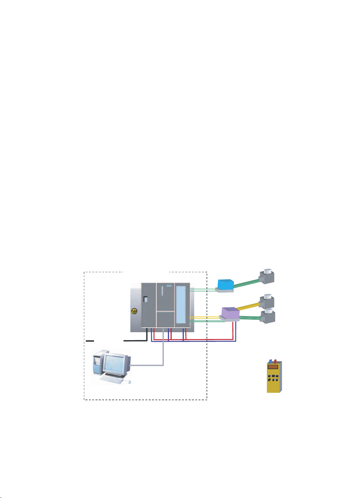
Overview
You want to connect three analog inputs to your station. One of them should have a 2-wire
current transducer and the other two should share a 4-wire current transducer.
You need failure diagnostic capabilities and want two sensors to be able to trigger hardware
interrupts.
You have the analog input module SM331, AI8x12 Bit (order number 6ES7 331-7KF020AB0) available. The module is diagnostic and hardware interrupt capable and can process
up to 8 analog inputs. The module is diagnostic and hardware interrupt capable and can
process up to 8 analog inputs (e.g. 4- 20 mA; PT 100; thermocouple).
6\VWHPH[DPSOH
36
&38 60
7ZR ZL U H
&XUUHQWWUDQVGXFHUV
3
(QFRGHU
9$&+]
RU
9$&+]
03,FDEOH
3URJUDPPLQJGHYLFH
Figure 3-1 Sample station components
SM331; AI 8x12 Bit Getting Started part 1: 4 -20mA
Getting Started, 11/2006, A5E00253410-02
9'&
)RXUZLUH
&XUUHQWWUDQVGXFHUV
(QFRGHU
(QFRGHU
&DOLEUDWLRQ
GHYLFH
3-1
Page 10

Introduction
3.1 Example of an application
In the following sections you will be introduced to:
● Mechanical setup of the example station
– General mounting instructions for S7-300 modules
– Configuration of the SM331 for the two selected measurement transducer types
● Electrical connection of the example station
– Wiring the power supply module and the CPU
– Wiring of the analog module
– Standard pin assignment of two measurement transducer types
– Wiring of unused inputs
● Configuring the SIMATIC Manager
– Using the project wizard
– Completing the automatically generated hardware configuration
– Integrating the supplied user program source
● User program testing
– Interpreting the read values
– Converting the measured values into readable analog values
● Utilizing the diagnostic capabilities of the SM331 module
– Triggering a diagnostic interrupt
– Evaluating the diagnostics:
● Application of hardware interrupts
– Configuration of hardware interrupts
– Configuration and analysis of hardware interrupts
SM331; AI 8x12 Bit Getting Started part 1: 4 -20mA
3-2 Getting Started, 11/2006, A5E00253410-02
Page 11
Mechanical setup of the example station
4.1 Mounting the example station
Overview
The setup of the example station is divided into two steps. First, the setup of the power
supply and the CPU is explained. After becoming acquainted with the analog module
SM331, the mounting of it is described.
Requirements
Before you can use the analog input module SM331, you need a basic setup of general
SIMATIC S7-300 components.
The order of the mounting takes place from left to right:
● Power supply PS307
● CPU 315-2DP
● SM331
4
Instructions (without SM331)
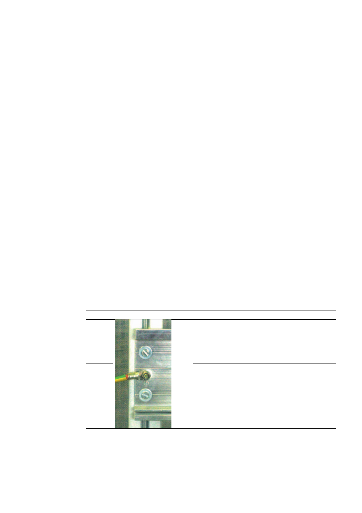
step Graphic controller Description
1 Screw on the mounting rail (screw size: M6) so that at
2
SM331; AI 8x12 Bit Getting Started part 1: 4 -20mA
Getting Started, 11/2006, A5E00253410-02
least 40 mm space remains above and below the rail.
When mounting it on a grounded steel panel or on a
grounded device mounting panel made of steel sheet,
make sure you have a low impedance connection
between the mounting rail and the mounting surface.
Connect the mounting rail with the protective conductor.
An M6 protective conductor screw is provided on the
mounting rail for this purpose.
4-1
Page 12
Mechanical setup of the example station
4.1 Mounting the example station
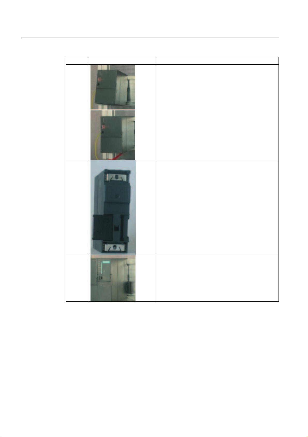
step Graphic controller Description
3
4
Mounting the power supply:
• Hang the power supply on to the top end of the rail
• Screw it tight to the rail underneath
Connect the bus connector (delivered with the SM331) to
the left connector on the back of the CPU
5
Mounting the CPU:
• Hang the CPU on to the top end of the rail
• Push it all the way left to the power supply
• Push it down
• Screw it tight to the rail underneath
SM331; AI 8x12 Bit Getting Started part 1: 4 -20mA
4-2 Getting Started, 11/2006, A5E00253410-02
Page 13

Mechanical setup of the example station
4.2 Mounting of analog module components
4.2 Mounting of analog module components
4.2.1 General
Overview
Before the actual mounting of the SM331 the module has to be completed with a front
connector and the desired measurement mode of the inputs is set.
In this section, you will learn about:
● The components you need
● The properties of the analog input module
● What a measuring range module is and how it is configured
● Mounting a configured module
SM331; AI 8x12 Bit Getting Started part 1: 4 -20mA
Getting Started, 11/2006, A5E00253410-02
4-3
Page 14
Mechanical setup of the example station
4.2 Mounting of analog module components
4.2.2 Components of the SM331
Overview
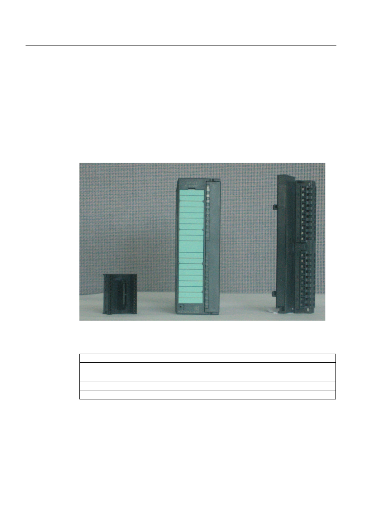
A functional analog module consists of the following components:
● Module SM331 (in our example 6ES7331-7KF02-0AB0)
● 20-pin front connector There are two different types of front connectors:
– With spring contacts (order number 6ES7392-1BJ00-0AA0)
– With screw contacts (order number 6ES7392-1AJ00-0AA0)
Figure 4-1 Components of the SM331
The scope of delivery of SM331
Components
Module
Labeling strips
Bus connectors
2 cable ties (not in the picture) to tie the external wiring
SM331; AI 8x12 Bit Getting Started part 1: 4 -20mA
4-4 Getting Started, 11/2006, A5E00253410-02
Page 15

Mechanical setup of the example station
4.2 Mounting of analog module components
4.2.3 Features of the analog modules
Characteristics
● 8 inputs in 4 channel groups (each group with two inputs of same type)
● Measurement resolution adjustable for each channel group
● User defined measuring mode per channel group:
– Voltage
– Current
– Resistance
– Temperature
● Programmable diagnostic interrupt
● Two channels with limit alarms (only channel 0 and channel 2 are configurable)
● Electrically isolated against backplane bus
● Electrically isolated against load voltage (exception: at least one module is set to position
D)
The module is a universal analog module designed for the most commonly used
applications.
The desired measuring mode should be set up directly on the module with the measuring
range modules.
SM331; AI 8x12 Bit Getting Started part 1: 4 -20mA
Getting Started, 11/2006, A5E00253410-02
4-5
Page 16
Mechanical setup of the example station
4.2 Mounting of analog module components
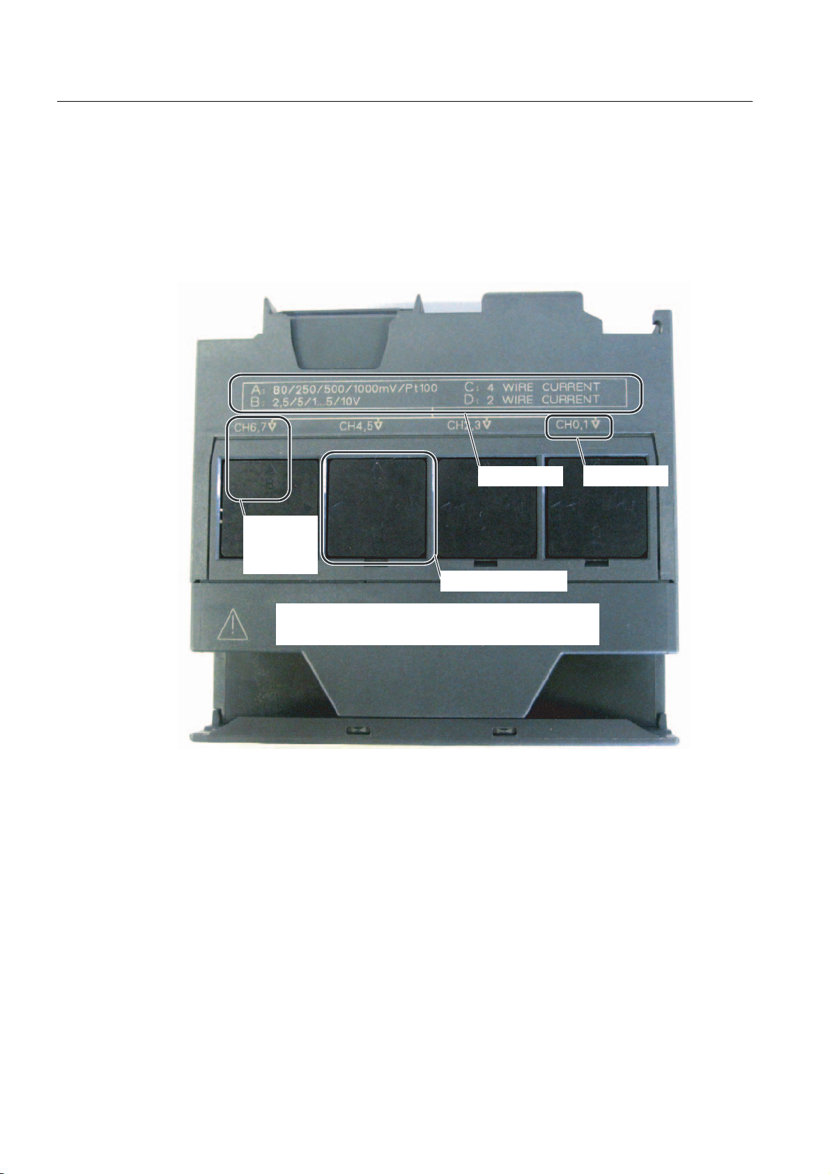
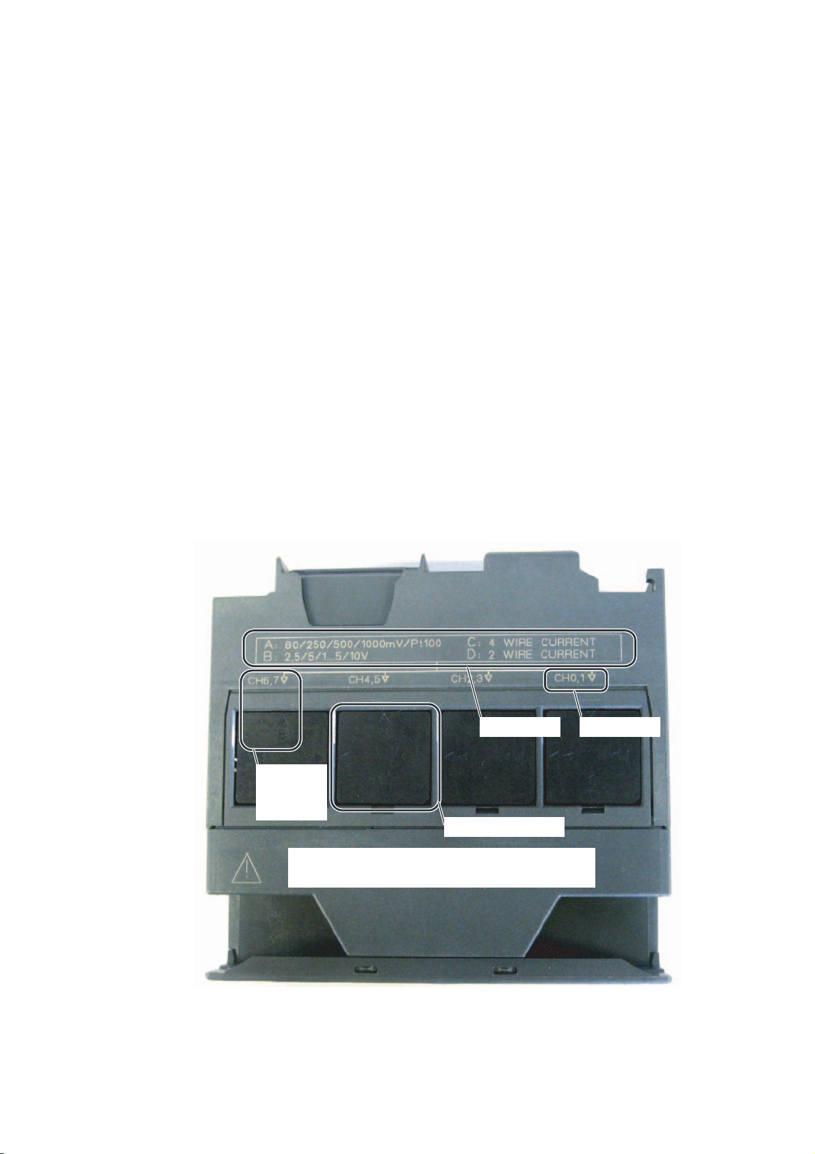
4.2.4 Measuring range modules
Terminal
The module SM331 has 4 measuring range modules (one per channel group). The
measuring range modules can be set to 4 different positions (A, B, C or D).
0HDVXULQJ
PRGH$'
3RVLWLRQ%
YROWDJH
VHWIRU&+
0HDVXULQJUDQJH
PRGXOH
5LVNRIGDPDJHZKHQPHDVXULQJUDQJHLVLQFRUUHFWO\VHW
'DQJHURIGDPDJHZKHQPHDVXULQJUDQJHLVLQFRUUHFWO\VHW
Figure 4-2 4 measuring range modules with default setting B (Voltage)
&KDQQHOJURXS
SM331; AI 8x12 Bit Getting Started part 1: 4 -20mA
4-6 Getting Started, 11/2006, A5E00253410-02
Page 17
Mechanical setup of the example station
4.2 Mounting of analog module components
Positions of the measuring range modules
The position enables you to specify the transducer to be connected to the respective channel
group.
Position Type of measurement
A Thermocouple / resistance measurement
B Voltage (factory setting)
C Current (4-wire transducer)
D Current (2-wire transducer)
In our example, a sensor with a 4 to 20mA 2-wire transducer is connected to channel group
1 at input 0.
A 4-wire transducer is connected to channel group 2 at inputs 2 and 3.
Therefore, the first measuring range module should have position D and the second should
have position C.
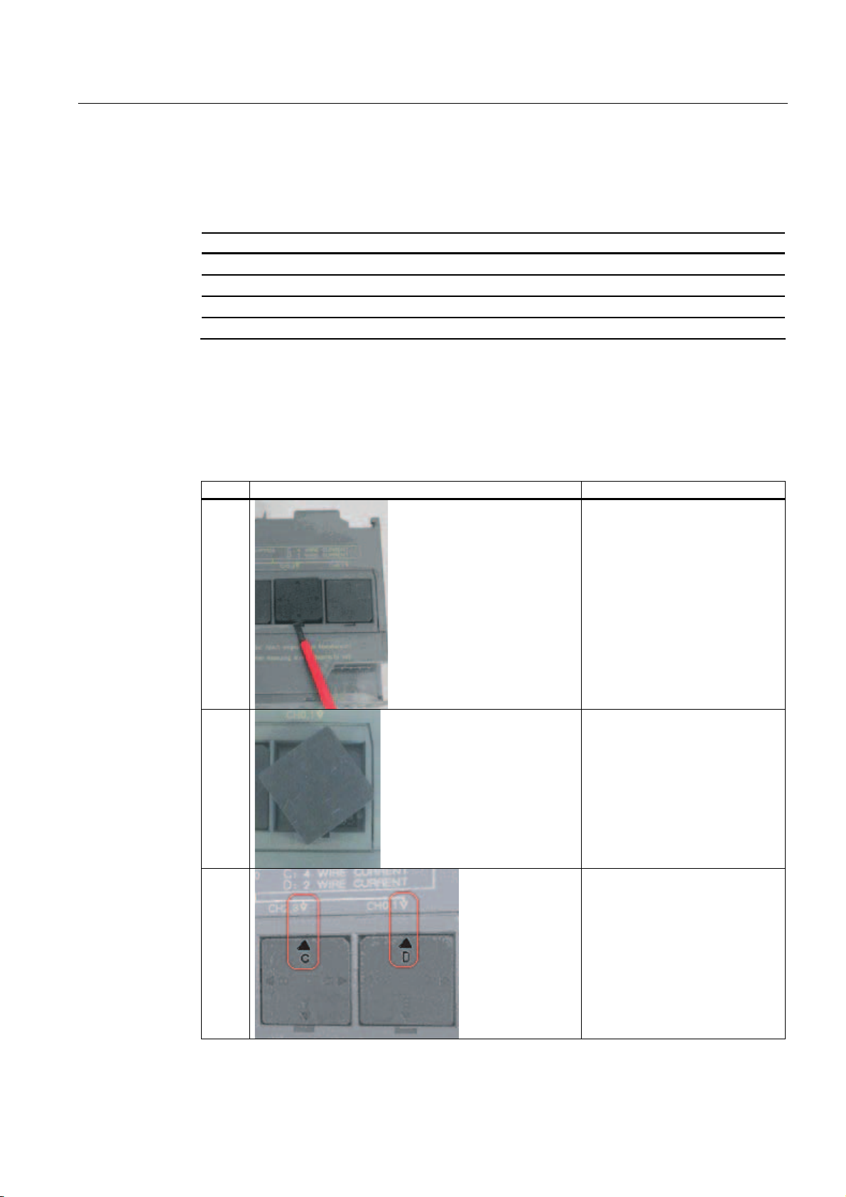
Positioning of the measuring range modules
step Graphic controller Description
1
With a screwdriver, pull out the
two measuring range modules
2
3
SM331; AI 8x12 Bit Getting Started part 1: 4 -20mA
Getting Started, 11/2006, A5E00253410-02
Turn the measuring range module
to the desired position:
Plug the measuring range module
back into the module
In our example, the module
should have the following
positions:
CH0,1: D
CH2,3: C
4-7
Page 18
Mechanical setup of the example station
4.2 Mounting of analog module components
Note
When you use a 2-wire transducer, the electrical isolation against the load voltage is lost for
all the channels in the module (at least one measuring range module is set to position D)
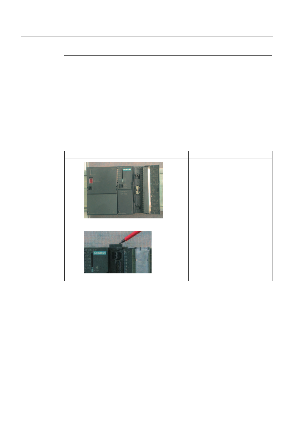
4.2.5 Mounting the SM331 module
Proceed as follows
After you have prepared the analog module accordingly, mount it to the rail as well.
step Graphic controller Description
1
Mounting the SM331:
• Hang the SM311 to the top end of
the rail
• Push it all the way to the left up to
the CPU
• Push it down
• Screw it tight to the rail underneath
2
The example station is now mechanically mounted.
Mounting the front connector:
• Press the upper release button of
the front terminal block
• Insert the front connector into the
module until it snaps in
SM331; AI 8x12 Bit Getting Started part 1: 4 -20mA
4-8 Getting Started, 11/2006, A5E00253410-02
Page 19

Electrical connection
5.1 Overview
Overview
This chapter shows you how the various parts of the example station are electrically wired
from the power supply to the analog module.
Warning
You might get an electrical shock if the power supply PS307 is turned on or the power cord
is connected to the line.
Always switch off power before you start wiring the S7-300.
5
SM331; AI 8x12 Bit Getting Started part 1: 4 -20mA
Getting Started, 11/2006, A5E00253410-02
5-1
Page 20
Electrical connection
5.2 Wiring the power supply module and the CPU
5.2 Wiring the power supply module and the CPU
Overview
Figure 5-1 Wiring the power supply module and the CPU
SM331; AI 8x12 Bit Getting Started part 1: 4 -20mA
5-2 Getting Started, 11/2006, A5E00253410-02
Page 21
Electrical connection
5.2 Wiring the power supply module and the CPU
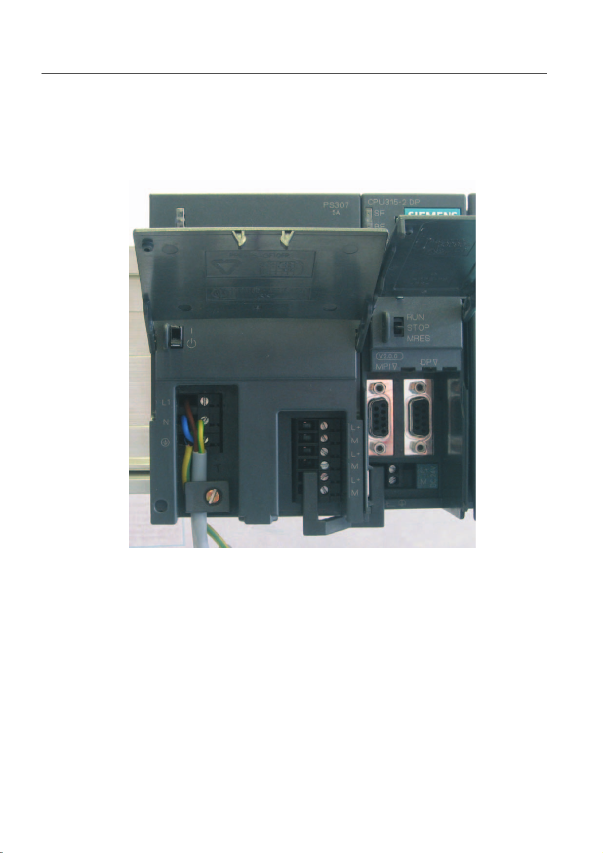
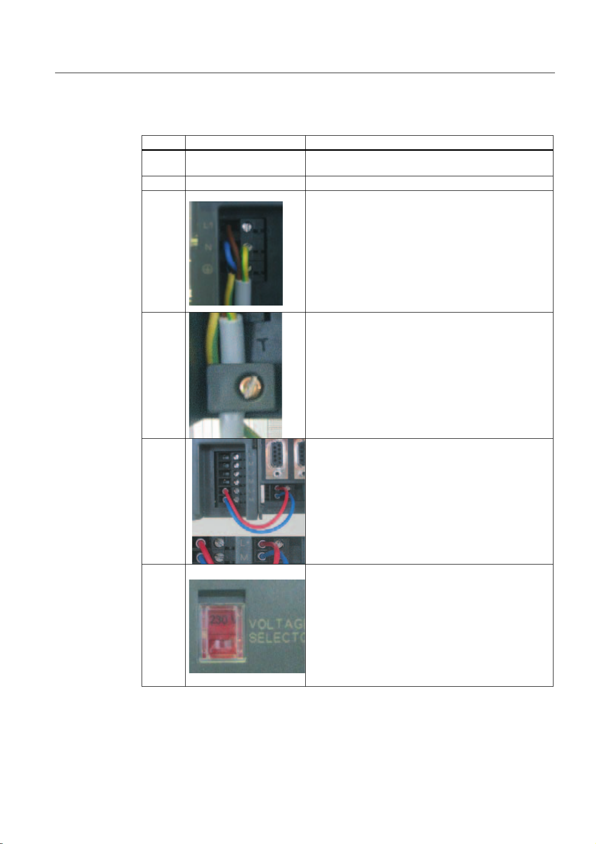
The example station requires a power supply. The wiring is done as follows:
Step Graphic controller Description
1 Open the front panel covers of the power supply module
and CPU.
2 Unscrew the cable grip on the power supply
3 Remove the insulation from the power cord, attach the cable
end sleeves (for stranded conductors) and connect it to the
power supply
4 Screw down the clamp of the cable grip.
5 Insert two connecting cables between the power supply and
the CPU and tighten them
6 Verify that the setting of the selector switch matches your
mains voltage.
The default line voltage setting for the power supply module
is 230 VAC. To change this setting, proceed as follows:
Remove the protective cap with a screwdriver, set the
selector switch to match your line voltage, then insert the
protective cap again.
SM331; AI 8x12 Bit Getting Started part 1: 4 -20mA
Getting Started, 11/2006, A5E00253410-02
5-3
Page 22
Electrical connection
5.3 Wiring of the analog module
5.3 Wiring of the analog module
5.3.1 Requirement
General
The wiring of an analog measurement transducer is depends on its type and not on the
SM331 module.
5.3.2 Current transducer wiring - principle
Options
Depending on the current transducer you use, you have to modify the wiring of the power
supply. We differentiate between the wiring of a 2-wire current transducer and a 4-wire
current transducer.
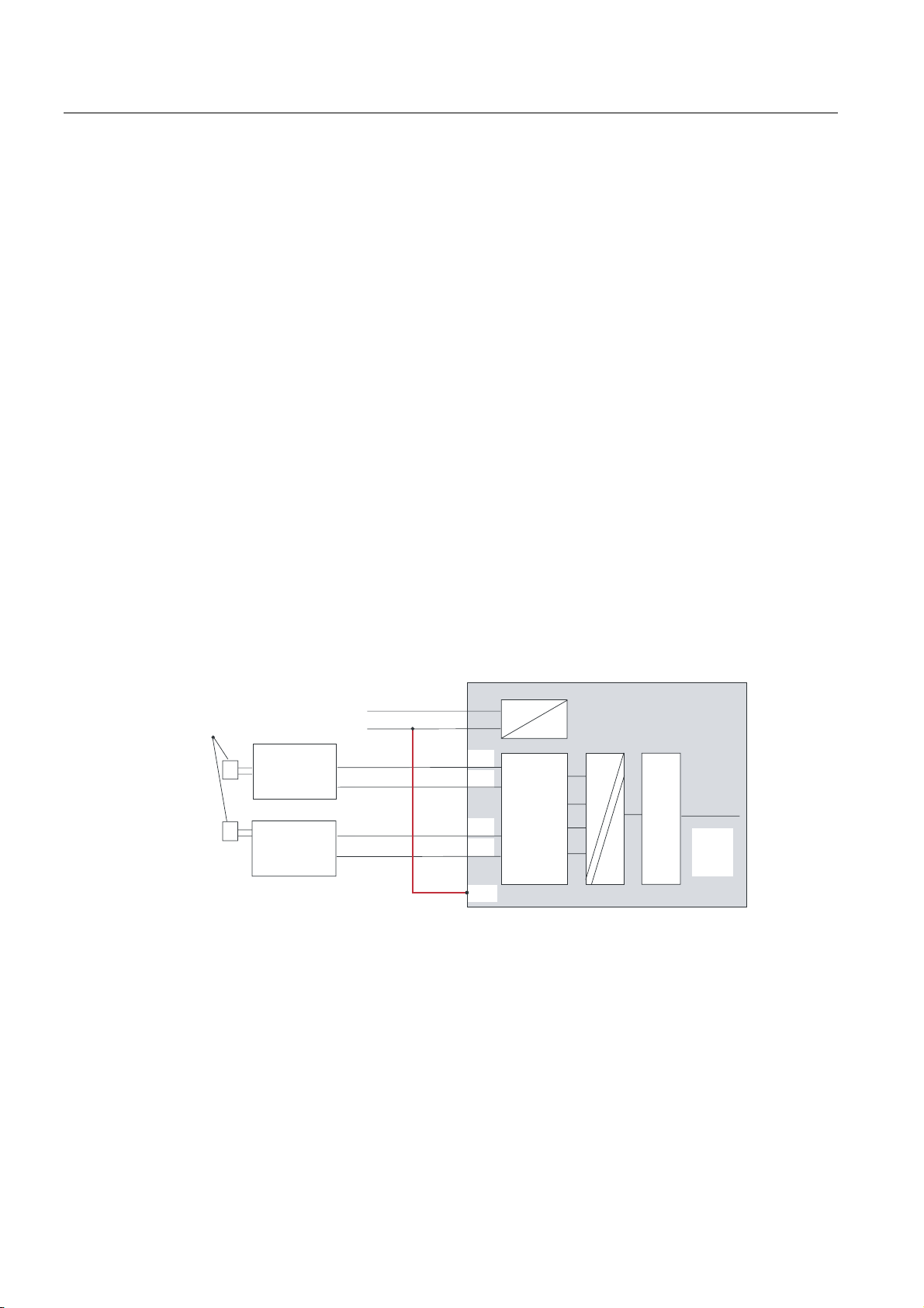
Wiring principles of a 2-wire current transducer
This transducer type is supplied with power from the analog input module.
6HQVRU
HJSUHVVXUHJDXJH
7ZR ZL U H
3
3
Figure 5-2 Wiring: 2-Wire current transducer
WUDQV
GXFHU
7ZR ZL U H
WUDQV
GXFHU
/
0
0
0
0
0
0DQD
$'&
/RJLF
%DFN
SDQH
EXV
SM331; AI 8x12 Bit Getting Started part 1: 4 -20mA
5-4 Getting Started, 11/2006, A5E00253410-02
Page 23
Electrical connection
5.3 Wiring of the analog module
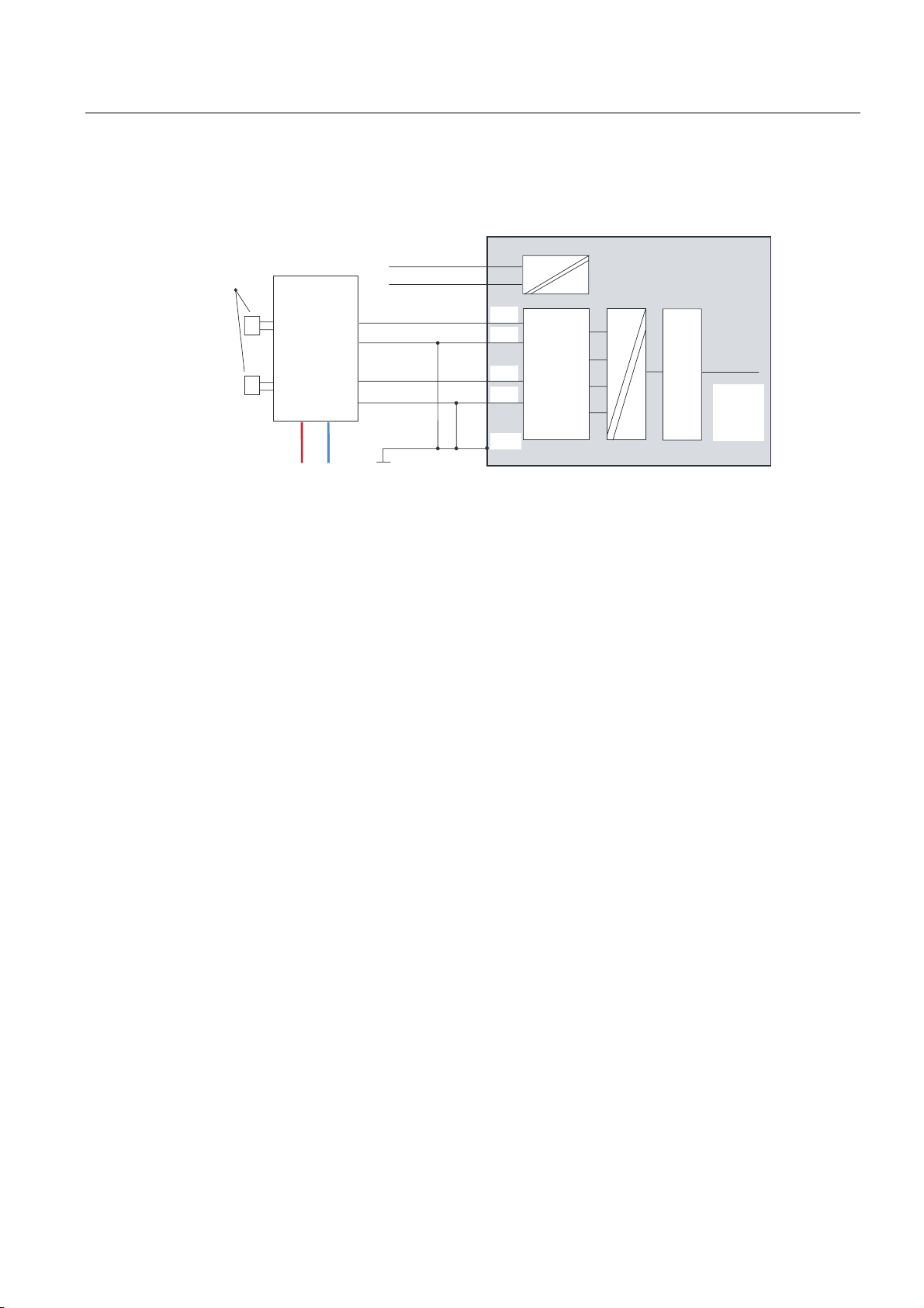
Wiring principles of a 4-wire current transducer
Unlike a 2-wire transducer, this transducer has its own power supply.
6HQVRU
HJSUHVVXUHJDXJH
/
0
)RXUZLUH
3
3
WUDQV
GXFHU
/ 0
Figure 5-3 Wiring: 4-Wire current transducer
5.3.3 Wiring of the analog module
Tasks
The wiring of the analog module consists of the following tasks:
● Connecting the power supply (red cable)
● Connecting the 2-wire current transducer (green cables)
0
0
0
0
0DQD
$'&
/RJLF
%DFN
SDQH
EXV
● Terminating unused channels with a resistor
● Connecting the 4-wire current transducer (green cables)
● Connecting the 4-wire current transducer (green cables)
● Connecting to ground and short-circuiting the other unused channels (blue wires)
SM331; AI 8x12 Bit Getting Started part 1: 4 -20mA
Getting Started, 11/2006, A5E00253410-02
5-5
Page 24

Electrical connection
5.3 Wiring of the analog module
SM331 Front connector wiring
Figure 5-4 SM331 Front connector wiring
Notice
Possible destruction of the module!
If you connect a defective 4-wire current transducer to an input, which is configured for a 2-
wire transducer, the module may be destroyed!
The required wiring tasks are explained below step-by-step:
SM331; AI 8x12 Bit Getting Started part 1: 4 -20mA
5-6 Getting Started, 11/2006, A5E00253410-02
Page 25

Electrical connection
5.3 Wiring of the analog module
Proceed as follows
Step Graphic
controller
1 Open the front door of the SM331 The connection diagram is
2 Remove 6 mm of the insulation from the
3
4
5
6
7
8
Connecting-up Comment
ends of the wires that go into the front
connector. Attach cable end sleeves to
these ends.
Wire the front connector as follows:
Terminal 1: L +
Terminal 2: M+ sensor 1
Terminal 3: M- sensor 1
Connect terminal 4 and 5 with a 1.5 to 3.3
kΩ resistor
Terminal 6: M+ sensor 2
Terminal 7: M- sensor 2
Terminal 8: M+ sensor 3
Terminal 9: M- sensor 3
terminal 10 (Comp) and
connect terminal 11 (M
ana
) to M
Short-circuit terminals 12 to 19 and
connect with M
ana
Terminal 20: M
printed on the front flap
Power supply of the module
Standard wiring for 2-wire
current transducer
In order to maintain the
diagnostic capability of channel
group 0, the second unused
input must be connected to a
resistor.
Standard wiring for 4-wire
current transducer
For measuring current comp is
not used
Mandatory for 2-wire current
transducers
Unused channel groups should
be short-circuited with M
ana
in
order to achieve a maximum
interference resistance
SM331; AI 8x12 Bit Getting Started part 1: 4 -20mA
Getting Started, 11/2006, A5E00253410-02
5-7
Page 26
Electrical connection
5.3 Wiring of the analog module
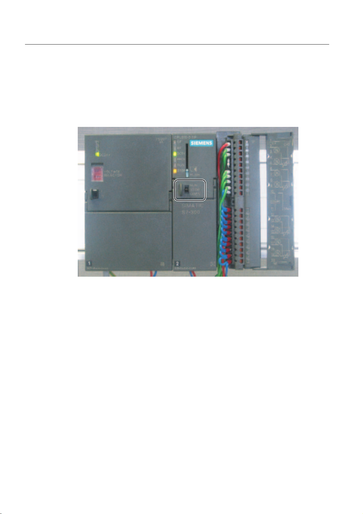
5.3.4 Test
Proceed as follows
If you want to test the wiring, you may now switch the power supply on.
Do not forget to set the CPU to STOP (see the red circle)
Figure 5-5 Successful wiring, CPU in position STOP
If a red LED is lit, then there is an error in the wiring. Verify your wiring.
SM331; AI 8x12 Bit Getting Started part 1: 4 -20mA
5-8 Getting Started, 11/2006, A5E00253410-02
Page 27
Configuration of the SIMATIC Manager
6.1 Creating a new STEP7 project
6.1.1 Creating a new project
"New Project..." Wizard
Use STEP7 V5.2 or later for configuring the new CPU 315-2 DP.
Start SIMATIC Manager by clicking the "SIMATIC Manager" icon on your Windows Desktop
and create a new project with the STEP7 "New Project" wizard.
6
3RVLWLRQ%
YROWDJH
VHWIRU&+
5LVNRIGDPDJHZKHQPHDVXULQJUDQJHLVLQFRUUHFWO\VHW
'DQJHURIGDPDJHZKHQPHDVXULQJUDQJHLVLQFRUUHFWO\VHW
Figure 6-1 Start the "New Project..." wizard
SM331; AI 8x12 Bit Getting Started part 1: 4 -20mA
Getting Started, 11/2006, A5E00253410-02
0HDVXULQJ
PRGH$'
0HDVXULQJUDQJH
PRGXOH
&KDQQHOJURXS
6-1
Page 28

Configuration of the SIMATIC Manager
6.1 Creating a new STEP7 project
A project wizard introduction window appears. The wizard guides you through the procedure
for creating a new project.
Figure 6-2 Wizard "New Project", start
The following must be specified during the creation procedure:
● The CPU type
● The basic user program
● The organization blocks
● Project name
Click "Next."
SM331; AI 8x12 Bit Getting Started part 1: 4 -20mA
6-2 Getting Started, 11/2006, A5E00253410-02
Page 29
Configuration of the SIMATIC Manager
6.1 Creating a new STEP7 project
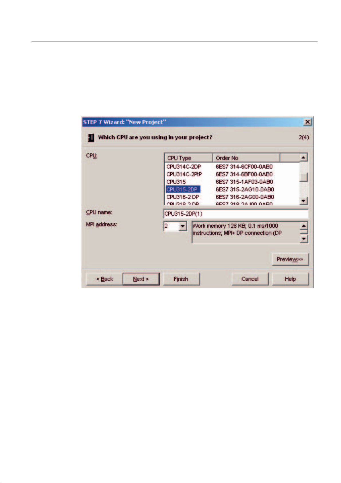
6.1.2 CPU selection
Proceed as follows
Choose the CPU 315-2DP for the example project. (You can also use our example for a
different CPU. Select the appropriate CPU in this case.)
Figure 6-3 "New Project" wizard: selecting a CPU
Click "Next."
SM331; AI 8x12 Bit Getting Started part 1: 4 -20mA
Getting Started, 11/2006, A5E00253410-02
6-3
Page 30
Configuration of the SIMATIC Manager
6.1 Creating a new STEP7 project
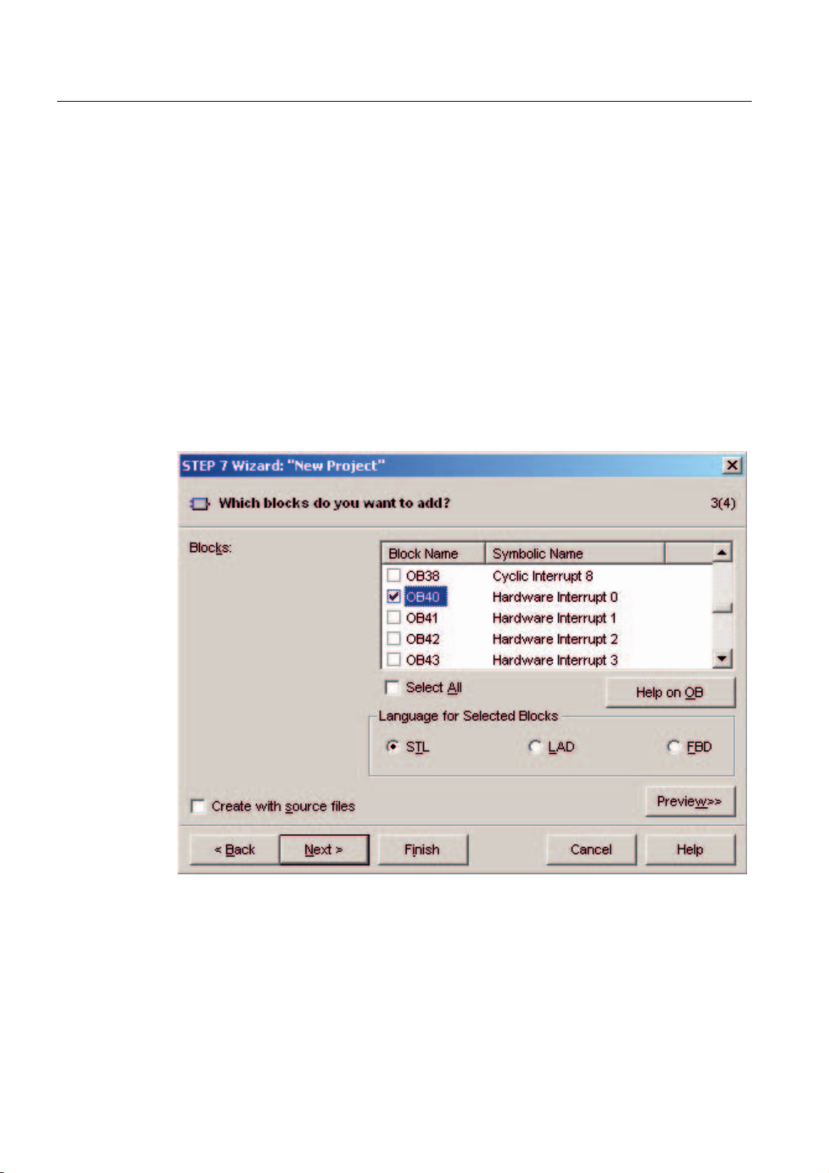
6.1.3 Defining the basic user program
Proceed as follows
Choose the SIMATIC language STL and select the following organization blocks (OBs):
● OB1 cyclically executed block
● OB40 hardware interrupt
● OB82 diagnostic interrupt
OB1 is required in every project and is called cyclically.
OB40 is called when a hardware interrupt occurs.
OB 82 is called when a diagnostic interrupt occurs.
If you use a module with diagnostic capabilities and OB82 is not inserted, the CPU changes
to STOP mode when a diagnostic alarm occurs.
Figure 6-4 "New Project" wizard: Inserting organization blocks
Click "Next."
SM331; AI 8x12 Bit Getting Started part 1: 4 -20mA
6-4 Getting Started, 11/2006, A5E00253410-02
Page 31
Configuration of the SIMATIC Manager
6.1 Creating a new STEP7 project
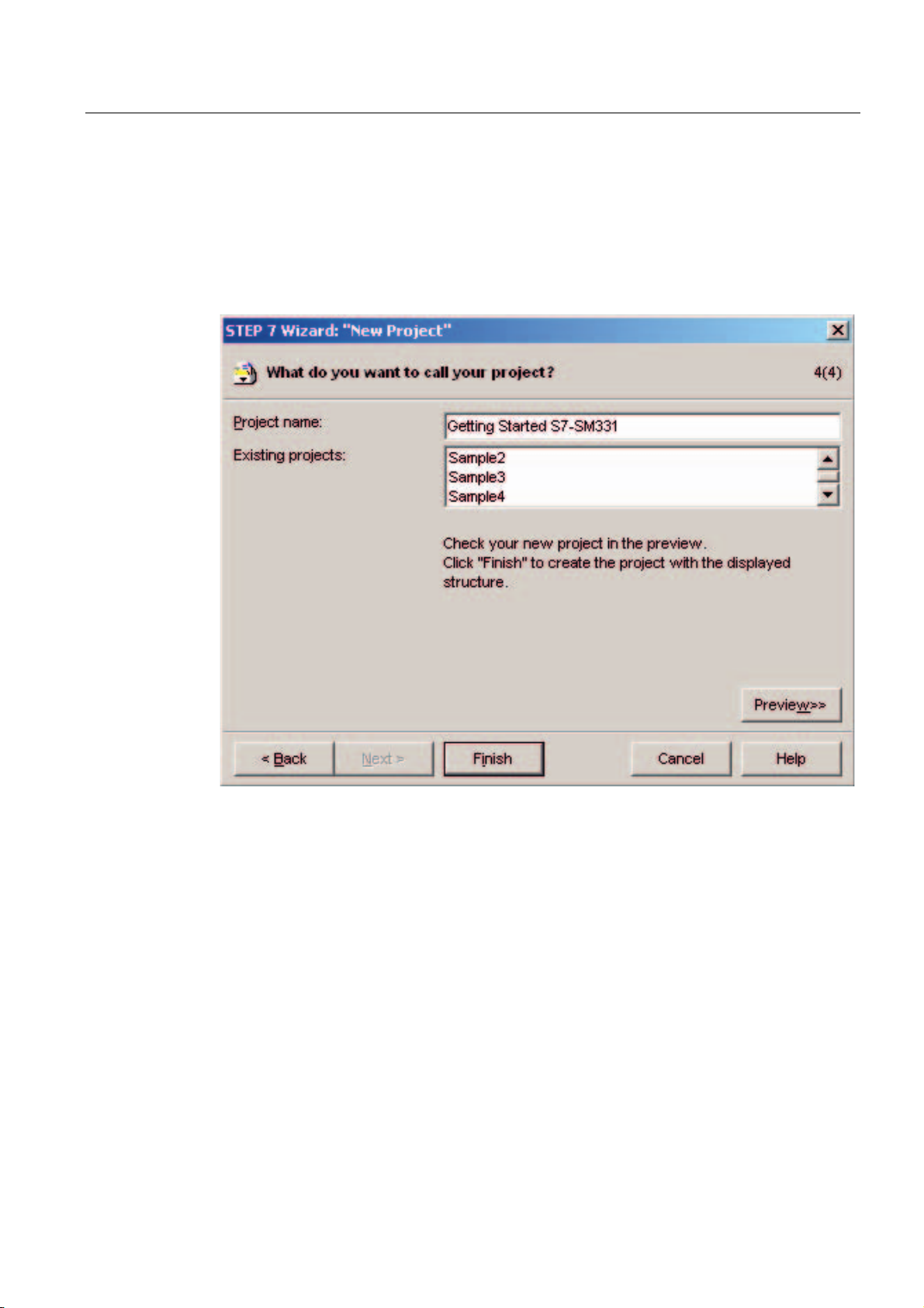
6.1.4 Assigning the project name
Proceed as follows
Select the “Project name” text box and overwrite the name in it with “Getting Started S7
SM331”.
Figure 6-5 "New Project" wizard: Assigning the project name
Click "Finish". The basic STEP7 project is created automatically.
SM331; AI 8x12 Bit Getting Started part 1: 4 -20mA
Getting Started, 11/2006, A5E00253410-02
6-3
Page 32

Configuration of the SIMATIC Manager
6.1 Creating a new STEP7 project
6.1.5 Result S7 project is created
Result
The wizard has created the project “Getting Started S7-SM331”. You can see the inserted
organization blocks in the right window.
Figure 6-6 "New Project" wizard results
SM331; AI 8x12 Bit Getting Started part 1: 4 -20mA
6-6 Getting Started, 11/2006, A5E00253410-02
Page 33

Configuration of the SIMATIC Manager
6.2 Hardware configuration
6.2 Hardware configuration
6.2.1 Creating the hardware configuration
Requirements
The STEP7 wizard has created a basic S7 project. You also need a complete hardware
configuration in order to create the system data for the CPU.
Proceed as follows
You can create the hardware configuration of the example station with SIMATIC Manager.
To do this, select the folder "SIMATIC 300 Station" in the left window. Start the hardware
configuration by double clicking the folder "Hardware" in the right window.
Figure 6-7 Opening the hardware configuration
SM331; AI 8x12 Bit Getting Started part 1: 4 -20mA
Getting Started, 11/2006, A5E00253410-02
6-3
Page 34

Configuration of the SIMATIC Manager
6.2 Hardware configuration
6.2.2 Adding SIMATIC components
Proceed as follows
First select a power supply module from the hardware catalog.
If the hardware catalog is not visible, open it with the shortcut key Ctrl+K or by clicking the
catalog icon (blue arrow).
In the hardware catalog you can browse through the folder SIMATIC 300 to the folder PS-
300.
Select the PS307 5A and drag it into slot 1 (see red arrow).
Figure 6-8 Hardware configuration: Basic configuration
Result: PS 307 5A appears in the configuration of your rack.
SM331; AI 8x12 Bit Getting Started part 1: 4 -20mA
6-8 Getting Started, 11/2006, A5E00253410-02
Page 35

Configuration of the SIMATIC Manager
6.2 Hardware configuration
Inserting an analog module
There are many SM331 analog modules. For this project we use an SM331, AI8x12 bit with
the order number 6ES7 331-7KF02-0AB0.
The order number is displayed at the bottom of the hardware catalog (see blue arrow).
Figure 6-9 Hardware configuration: SM331 insert
Drag the module into the first available field at slot 4 of your rack (see red arrow).
You have inserted all the modules into the hardware configuration. In the next step, you
configure the modules.
SM331; AI 8x12 Bit Getting Started part 1: 4 -20mA
Getting Started, 11/2006, A5E00253410-02
6-3
Page 36

Configuration of the SIMATIC Manager
6.2 Hardware configuration
6.2.3 Configuring the analog module
Overview
SIMATIC Manager inserts the analog module with its default settings. You can modify the
parameters to change the sensor types, diagnostics and interrupt capabilities.
Mounting the example station
The table shows, which parameters have to be set for our example station.
SM331 functions of the example station
Functions Description
Process reactions
Encoder 1
Encoder 2 & 3
• Diagnostics – enabled
• Hardware interrupt when limit exceeded - enabled
• 2-Wire current transducer
• Group diagnostics
• Check for wire break
• Measuring range 6 mA and 18 mA
• 4-Wire current transducer
• Group diagnostics
• Check for wire break
• Measuring range 6 mA and 18 mA
SM331; AI 8x12 Bit Getting Started part 1: 4 -20mA
6-10 Getting Started, 11/2006, A5E00253410-02
Page 37

Configuration of the SIMATIC Manager
6.2 Hardware configuration
Opening the configuration
Double-click on slot 4 that has the SM331 in it.
Select the "Inputs" tab.
Configure the following functions:
● Diagnostic interrupt enabled
● Hardware interrupt enabled
● Input 0-1:
– Type of measurement: 2DMU
– Group diagnostics enabled
– Wire break enabled
● Input 2-3:
– Type of measurement: 2DMU
– Group diagnostics enabled
– Wire break enabled
● Input 4-5 and 6-7
– Type of measurement: Disabled (---)
● Interference frequency
– Select your power frequency (50 Hz or 60 Hz)
● Hardware interrupt trigger
– Upper limit value 18 mA
– Lower limit value 6 mA
Figure 6-10 SM331: Configuration
SM331; AI 8x12 Bit Getting Started part 1: 4 -20mA
Getting Started, 11/2006, A5E00253410-02
6-3
Page 38

Configuration of the SIMATIC Manager
6.2 Hardware configuration
Explanation of the individual settings
Measuring type:
2DMU and 4DMU stand for 2-wire and 4-wire current transducers
--- means that the channels are deactivated. If you deactivate channels, the remaining
channels are processed faster.
Measuring range modules
The required setting of the measuring range module is displayed.
Interference frequency (Interference frequency suppression)
The frequency of your AC power system can interfere with the measured value, particularly
when measuring in low voltage ranges and using thermocouple elements. With this
parameter you specify the frequency of your power supply on site.
This parameter also influences the granularity, integration time and the basic execution
period of the channel group.
● Resolution (accuracy)
The analog value is stored in a 16-bit word.
● Integration time
The module requires a certain amount of time to measure the analog signal. This time is
called integration time. The higher the required accuracy is, the longer the module needs
for measuring the voltage.
● Basic processing time
Besides the integration time, the module also needs a certain amount of time to provide
the binary value.
Relationship between accuracy, interference frequency and integration period
Resolution Interference
frequency
9 bits 400 Hz 2.5 ms 24 ms
12 bits 60 Hz 16.6 ms 136 ms
12 bits 20 Hz 20 ms 176 ms
14 bits 10 Hz 100 ms 816 ms
Hardware interrupt:
Only the channels 0 and 2 have hardware interrupt capabilities. You can use hardware
interrupts to trigger an alarm when the analog signal exceeds its high or low limit.
Finish the hardware configuration:
Close the window with the configuration.
Compile and save the project with the command Station > Save and Compile (Ctrl+S)
Integration time Basic processing time
This completes your hardware configuration for the project.
SM331; AI 8x12 Bit Getting Started part 1: 4 -20mA
6-12 Getting Started, 11/2006, A5E00253410-02
Page 39

Configuration of the SIMATIC Manager
6.2 Hardware configuration
6.2.4 Test
Proceed as follows
For testing, do a power up test and download the system data.
Step Graphic controller Description
1 Erase your Micro Memory Card
with a Power PG or a PC with
external programming device:
In SIMATIC Manager click "File ->
S7 Memory Card > Delete …".
The MCC will be deleted.
2
3
4
5
Switch off the power supply to the
CPU.
Insert the MMC into the CPU.
Switch on the power supply.
If the CPU is in RUN mode, set it
to STOP mode.
Switch the power supply on again.
If the STOP LED blinks, the CPU
requests a reset. Acknowledge
this by turning the mode switch to
MRES for a moment.
Connect the CPU to the PG with
an MPI cable.
To do this, connect the MPI cable
with the CPU’s MPI port. Connect
the other end to the PG interface
of your programming device.
SM331; AI 8x12 Bit Getting Started part 1: 4 -20mA
Getting Started, 11/2006, A5E00253410-02
6-3
Page 40

Configuration of the SIMATIC Manager
6.2 Hardware configuration
Downloading hardware configuration
Download the hardware configuration into the CPU with HW Config.
Figure 6-11 Download CPU hardware configuration (1)
SM331; AI 8x12 Bit Getting Started part 1: 4 -20mA
6-14 Getting Started, 11/2006, A5E00253410-02
Page 41

Configuration of the SIMATIC Manager
6.2 Hardware configuration
Click the "Load to module" icon (shown in the red circle).
When the dialog window "Select target module" appears, click OK.
Figure 6-12 Download CPU hardware configuration (2)
The dialog window "Select target address" is shown. Click "OK." The system data will now
be transferred to the CPU.
SM331; AI 8x12 Bit Getting Started part 1: 4 -20mA
Getting Started, 11/2006, A5E00253410-02
6-3
Page 42
Configuration of the SIMATIC Manager
6.2 Hardware configuration
Starting the CPU
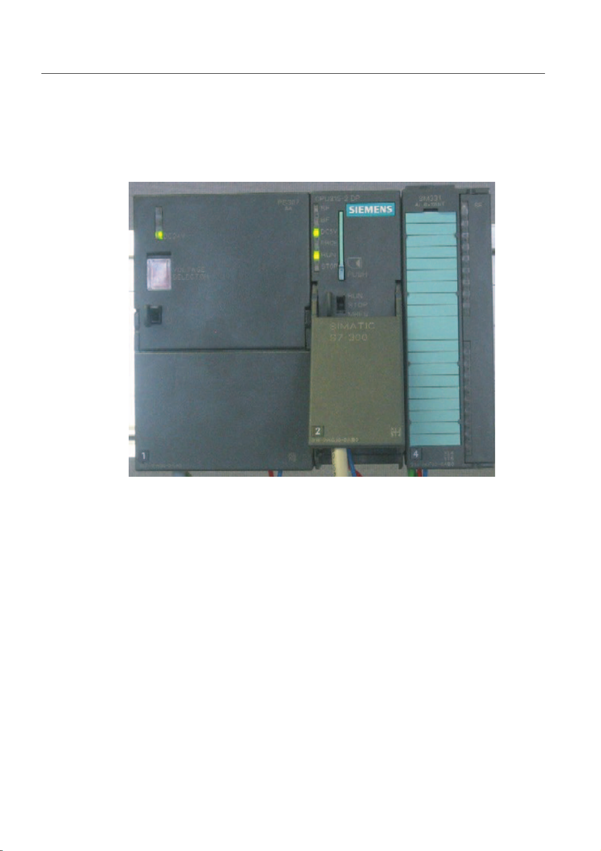
Switch the CPU to RUN.
If the hardware configuration was undertaken correctly, two red LEDs (RUN and DC5V)
should be lit on the CPU.
Figure 6-13 CPU in error free state
SM331; AI 8x12 Bit Getting Started part 1: 4 -20mA
6-16 Getting Started, 11/2006, A5E00253410-02
Page 43

Configuration of the SIMATIC Manager
6.3 STEP 7 user program
6.3 STEP 7 user program
6.3.1 Tasks of the user program
Overview
In our example, the sensor values are stored in a data block. Also, the hardware interrupt
status should be stored in a marker word. It should be possible to acknowledge the status
information by means of a bit.
Furthermore, the channel values (values of the input words) should be stored in another data
block.
The following tasks have to be performed in the user program:
● Cyclical storage of the analog input values in a data block (DB1)
● Cyclical conversion of the analog input values in floating point values (FC1) and storage
in a data block (DB2)
About OB82
● Acknowledgement of the hardware interrupt status when the acknowledge marker
(M200.0) is TRUE.
● Save the status in a marker word (MW100) when a hardware interrupt occurs.
The structure of the user program is depicted in the following table:
Call type Responsible
organization block
Cyclic
execution
Convert and store the
Acknowledge hardware
Hardware
interrupt
triggered call
Diagnostic
interrupt
triggered call
OB1 Save analog input
OB40 Save status MW100
OB82 Has to be implemented
Task to be programmed Used block or marker
DB1
values
FC1, DB2
sensor values
M200.0
interrupt
--because a module with
diagnostic capabilities
is used
OB82 is used for modules with diagnostic capabilities. If the diagnostic alarm is enabled for
such modules, OB82 requests for diagnoses when a failure is detected (incoming and
outgoing events). The operating system then calls OB 82.
In our example, we use OB82 to prevent the CPU from changing to STOP mode. You can
program reactions to diagnostic interrupts in OB82.
SM331; AI 8x12 Bit Getting Started part 1: 4 -20mA
Getting Started, 11/2006, A5E00253410-02
6-3
Page 44

Configuration of the SIMATIC Manager
6.3 STEP 7 user program
6.3.2 Creating a user program
Proceed as follows
There are two ways to create a user program.
● If you know how to program STEP7 SCL, then you can create and program the
necessary blocks and the function blocks in the Blocks folder of STEP7.
● You can insert the user program from an SCL source into the project. In this “Getting
started” we describe this method.
Creating a user program in STEP7 requires three steps:
1. Downloading the source file directly from the HTML page
2. Importing a source file
3. Compiling the source
Downloading the source file
You can download the source file directly from the HTML page from which you loaded this
“Getting Started”.
The German version of the source file has the name "GSSM331T1DE.AWL".
Save the source file to your hard drive.
SM331; AI 8x12 Bit Getting Started part 1: 4 -20mA
6-18 Getting Started, 11/2006, A5E00253410-02
Page 45

Configuration of the SIMATIC Manager
6.3 STEP 7 user program
Importing a source file
You can import the source file into SIMATIC Manager as follows:
Right click the folder "Sources".
Select "Insert new Object > External Source...".
Figure 6-14 Importing an external source
SM331; AI 8x12 Bit Getting Started part 1: 4 -20mA
Getting Started, 11/2006, A5E00253410-02
6-3
Page 46
Configuration of the SIMATIC Manager
6.3 STEP 7 user program
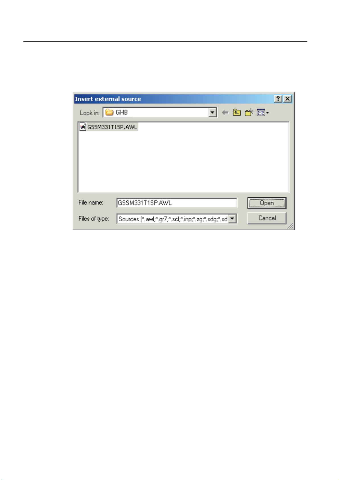
In the "Insert external source" dialog browse for the source file GSSM331T1DE.AWL, which
you have already downloaded and saved on your hard disk.
Select the source file GSSM331T1DE.AWL (red arrow).
Figure 6-15 Importing an external source
SM331; AI 8x12 Bit Getting Started part 1: 4 -20mA
6-20 Getting Started, 11/2006, A5E00253410-02
Page 47
Configuration of the SIMATIC Manager
6.3 STEP 7 user program
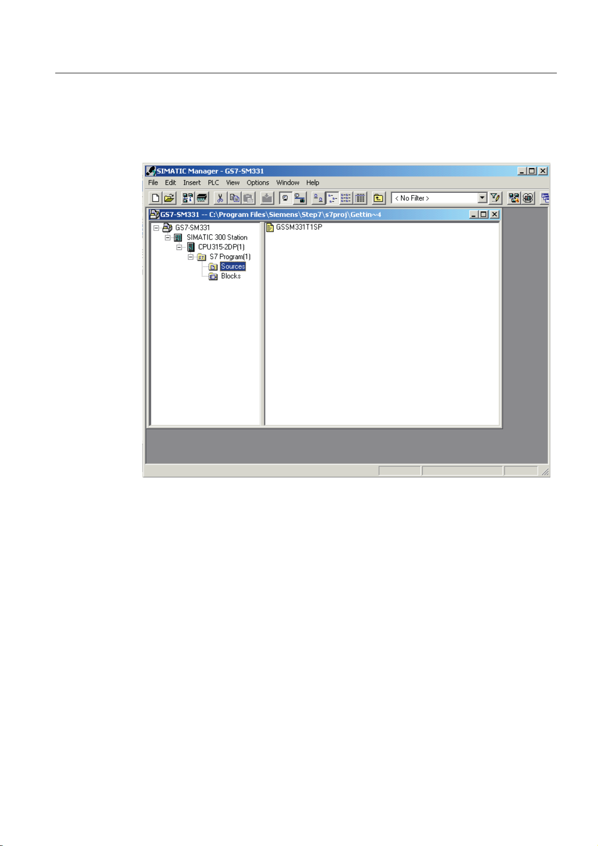
Click "Open".
SIMATIC Manager has opened the source file. In the right window you can see the source
file inserted.
Figure 6-16 Compiling the source code
SM331; AI 8x12 Bit Getting Started part 1: 4 -20mA
Getting Started, 11/2006, A5E00253410-02
6-3
Page 48

Configuration of the SIMATIC Manager
6.3 STEP 7 user program
Compiling the source code
In order to create an executable STEP7 program, the STL source has to be compiled.
Double-click the source file GSSM331T1DE in the Sources folder. The source code editor
opens.
In the window of the source code editor you can view the source code.
Figure 6-17 Source code editor
SM331; AI 8x12 Bit Getting Started part 1: 4 -20mA
6-22 Getting Started, 11/2006, A5E00253410-02
Page 49

Configuration of the SIMATIC Manager
6.3 STEP 7 user program
After the source code is loaded, start the compilation.
Press the shortcut key Ctrl+B or select File > Compile. The compilation starts immediately.
Figure 6-18 Compiling STL source
SM331; AI 8x12 Bit Getting Started part 1: 4 -20mA
Getting Started, 11/2006, A5E00253410-02
6-3
Page 50

Configuration of the SIMATIC Manager
6.3 STEP 7 user program
In case of warning or error messages, check the source code.
Figure 6-19 Source code editor, messages after compilation
SM331; AI 8x12 Bit Getting Started part 1: 4 -20mA
6-24 Getting Started, 11/2006, A5E00253410-02
Page 51

Configuration of the SIMATIC Manager
6.3 STEP 7 user program
Close the source code editor.
After compiling the STL source without errors the following blocks should appear in the
Blocks folder:
OB1, OB40, OB82, FC1, DB1 and DB2
Figure 6-20 Generated blocks
SM331; AI 8x12 Bit Getting Started part 1: 4 -20mA
Getting Started, 11/2006, A5E00253410-02
6-3
Page 52

Configuration of the SIMATIC Manager
6.3 STEP 7 user program
SM331; AI 8x12 Bit Getting Started part 1: 4 -20mA
6-26 Getting Started, 11/2006, A5E00253410-02
Page 53

Testing the user program
7.1 Downloading system data and user program
Proceed as follows
The hardware and software are now ready. The next step is to download the system data
and the user program into the automation system. To do this, proceed as follows:
Downloading the system data and user program
Step Graphic controller Description
1 Using the SIMATIC Manager,
7
download the user program and the
system data (containing the
hardware configuration) into the
CPU.
2
SM331; AI 8x12 Bit Getting Started part 1: 4 -20mA
Getting Started, 11/2006, A5E00253410-02
Follow the instructions displayed on
the screen.
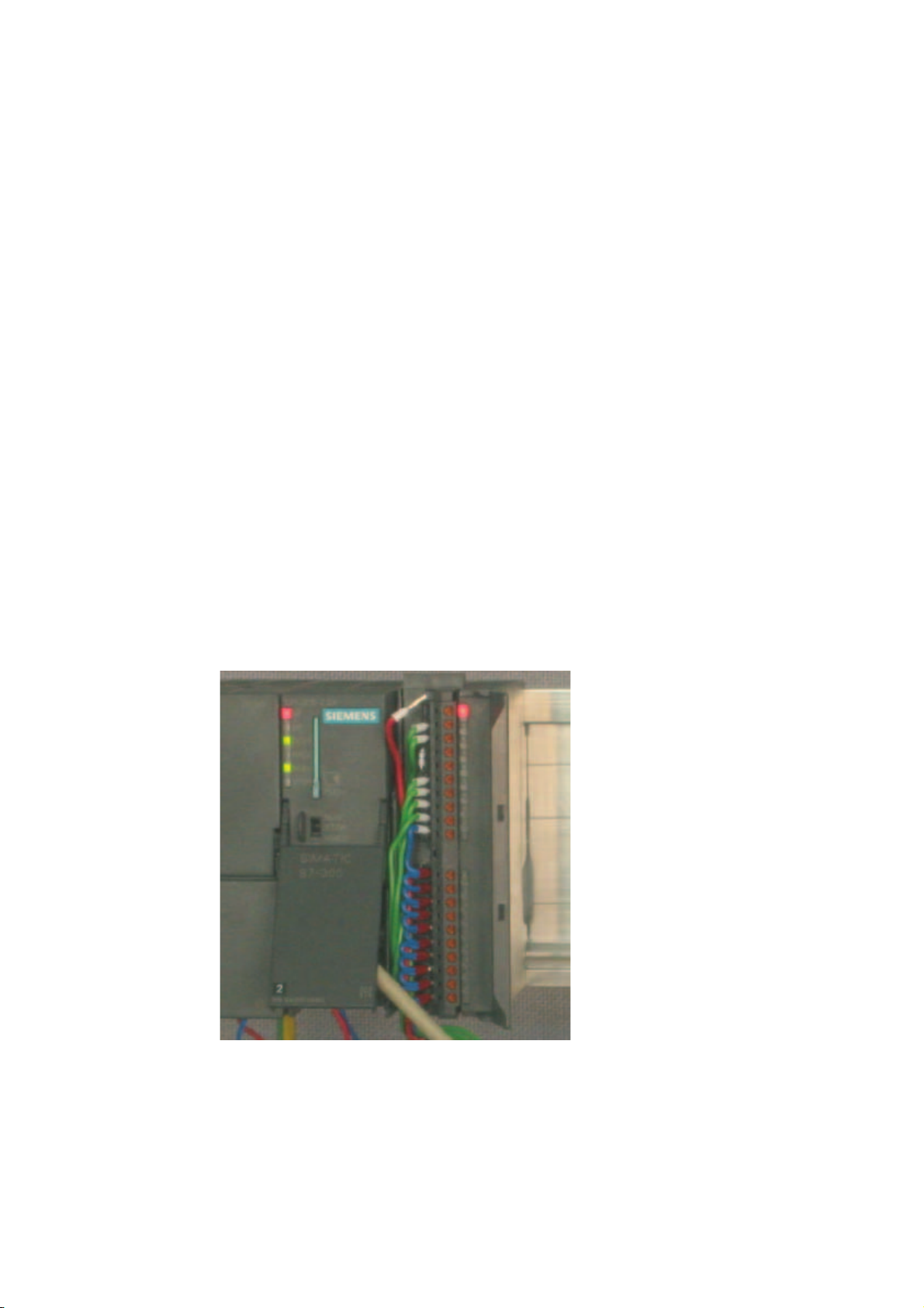
If all sensors are properly
connected, the CPU and the SM331
do not display an error light.
The status of the CPU is displayed
by the green "RUN" light.
7-1
Page 54

Testing the user program
7.1 Downloading system data and user program
Smart Label
The labeling strips for the modules were created with Siemens S7 Smart Label (order no:
2XV9 450-1SL01-0YX0).
A labeling strip in its actual size:
Figure 7-1 S7-SmartLabel labeling strip for the example
SM331; AI 8x12 Bit Getting Started part 1: 4 -20mA
7-2 Getting Started, 11/2006, A5E00253410-02
Page 55

Testing the user program
7.2 Visualization of the sensor values
7.2 Visualization of the sensor values
Proceed as follows
In order to visualize the sensor values, insert a variable table as follows into the project. To
do this, select from the context menu of the Blocks folder:
Insert new object > Variable Table
Figure 7-2 Insert Variable Table
SM331; AI 8x12 Bit Getting Started part 1: 4 -20mA
Getting Started, 11/2006, A5E00253410-02
7-3
Page 56

Testing the user program
7.2 Visualization of the sensor values
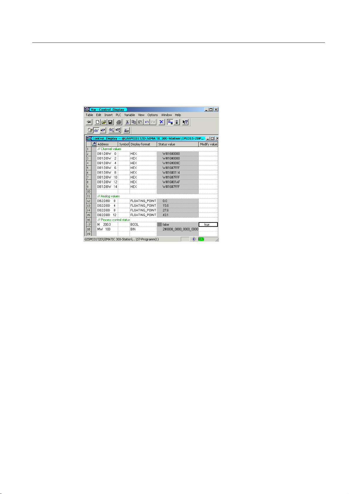
Fill the new variable table as follows:
(1) In this area you can monitor the channel values
(2) In this area you can see the analog values
(3) In this area you can monitor and control the status signals
SM331; AI 8x12 Bit Getting Started part 1: 4 -20mA
7-4 Getting Started, 11/2006, A5E00253410-02
Page 57

Testing the user program
7.2 Visualization of the sensor values
Variable description
Variables Description
DB1.DBW 0 Channel 0 Display of analog value
DB1.DBW 2 Channel 1 Display of analog value
DB1.DBW 4 Channel 2 Display of analog value
DB1.DBW 6 Channel 3 Display of analog value
DB1.DBW 8 Channel 4 Display of analog value
DB1.DBW 10 Channel 5 Display of analog value
DB1.DBW 12 Channel 6 Display of analog value
DB1.DBW 14 Channel 7 Display of analog value
DB2.DBD 0 Transducer1 current (mA)
DB2.DBD 4 Transducer2 current (mA)
DB2.DBD 8 Transducer3 current (mA)
MW 100 Status hardware interrupt
MW 200.0 Acknowledge hardware interrupt
M101.0 Channel 0 exceeded low limit
M101.1 Channel 0 exceeded high limit
M101.2 Channel 2 exceeded low limit
M101.3 Channel 0 exceeded high limit
SM331; AI 8x12 Bit Getting Started part 1: 4 -20mA
Getting Started, 11/2006, A5E00253410-02
7-3
Page 58
Testing the user program
7.2 Visualization of the sensor values
Monitoring values
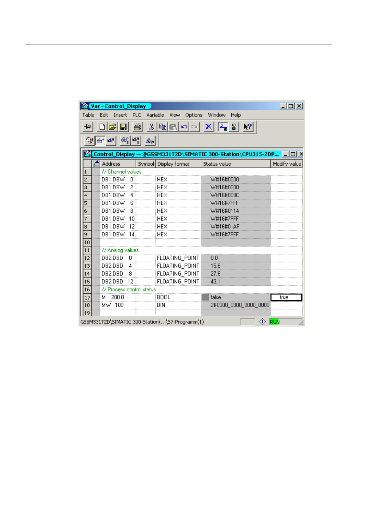
In order to monitor values, open the online view of the controller by clicking the eye glasses
symbol. Now you can monitor the values in the data blocks and markers.
Figure 7-3 Online view of the variable table
(1) Channel values in hex format
(2) Converted analog value
(3) Status information
SM331; AI 8x12 Bit Getting Started part 1: 4 -20mA
7-6 Getting Started, 11/2006, A5E00253410-02
Page 59
Testing the user program
7.2 Visualization of the sensor values
Controlling values
To control the process acknowledgement, enter the desired value (TRUE or FALSE,
depending on whether you want to activate or deactivate acknowledgement) into the column
"Control Value" and click the icon with the two arrows.
Controlling variables
(1) Channel value
(2) Analog value
(3) Status
Peculiarity in monitoring the values
While monitoring the values you will surely notice that the channel values are different from
the analog values. The reason for this is that the analog module only supports the binary
format “Word” (16 bits). Therefore, the values of the analog module have to be converted.
SM331; AI 8x12 Bit Getting Started part 1: 4 -20mA
Getting Started, 11/2006, A5E00253410-02
7-3
Page 60

Testing the user program
7.3 Analog value representation
7.3 Analog value representation
Proceed as follows
The analog values are only processed by the CPU in binary form. Analog input modules
convert the analog process signal into a digital format (16 bit word).
Five ranges have to be taken into account when converting from digital to analog values:
Representation of analog values in current measuring ranges 4 to 20 mA
Hex value Current range Comment Meaning
7FFF 22.96 mA
7F00
7EFF 22.81 mA
6C01
6C00 20 mA
5100 15 mA
1 4 mA + 578.7 nA
0 4 mA
FFFF
ED00 1.185 mA
ECFF
8000
Overflow From hex value 16#F700 on, the sensor
value is above the configured measurement
value range and is no more valid.
Overload range This range corresponds to a tolerance band
before the overflow range is reached. Within
this range the resolution is not optimal
though.
Rated range The nominal range is the normal range for
recording measurement values. This range
guarantees optimal resolution.
Underload range Range corresponding to the overload range
but for low values.
Underflow From hex value 16#ECFF on, the sensor
value is below the configured measurement
value range and is no more valid.
It is necessary to convert the binary format of the values in order to display analog process
values. In our example, mA are displayed. This is done by converting the display of analog
values in mA in a programmed function (FC1).
Note
In our example, we look at the values from the output of the transducer.
Using a amperemeter, you can now compare the values on the meter with the values of the
analog values display. The values will be identical.
SM331; AI 8x12 Bit Getting Started part 1: 4 -20mA
7-8 Getting Started, 11/2006, A5E00253410-02
Page 61
Diagnostic interrupt
8.1 Reading diagnostic information from a PG
Overview
Diagnostic interrupts enable the user program to react to hardware errors.
Modules must have diagnostic capabilities in order to generate diagnostic interrupts.
In OB82 you program the reaction to diagnostic interrupts.
Display
The analog input module SM331 AI8x12 has diagnostic capabilities.
Diagnostic interrupts that occur are signaled by the red "SF" LED on the SM331 and on the
CPU.
8
Figure 8-1 Hardware error
SM331; AI 8x12 Bit Getting Started part 1: 4 -20mA
Getting Started, 11/2006, A5E00253410-02
8-1
Page 62
Diagnostic interrupt
8.1 Reading diagnostic information from a PG
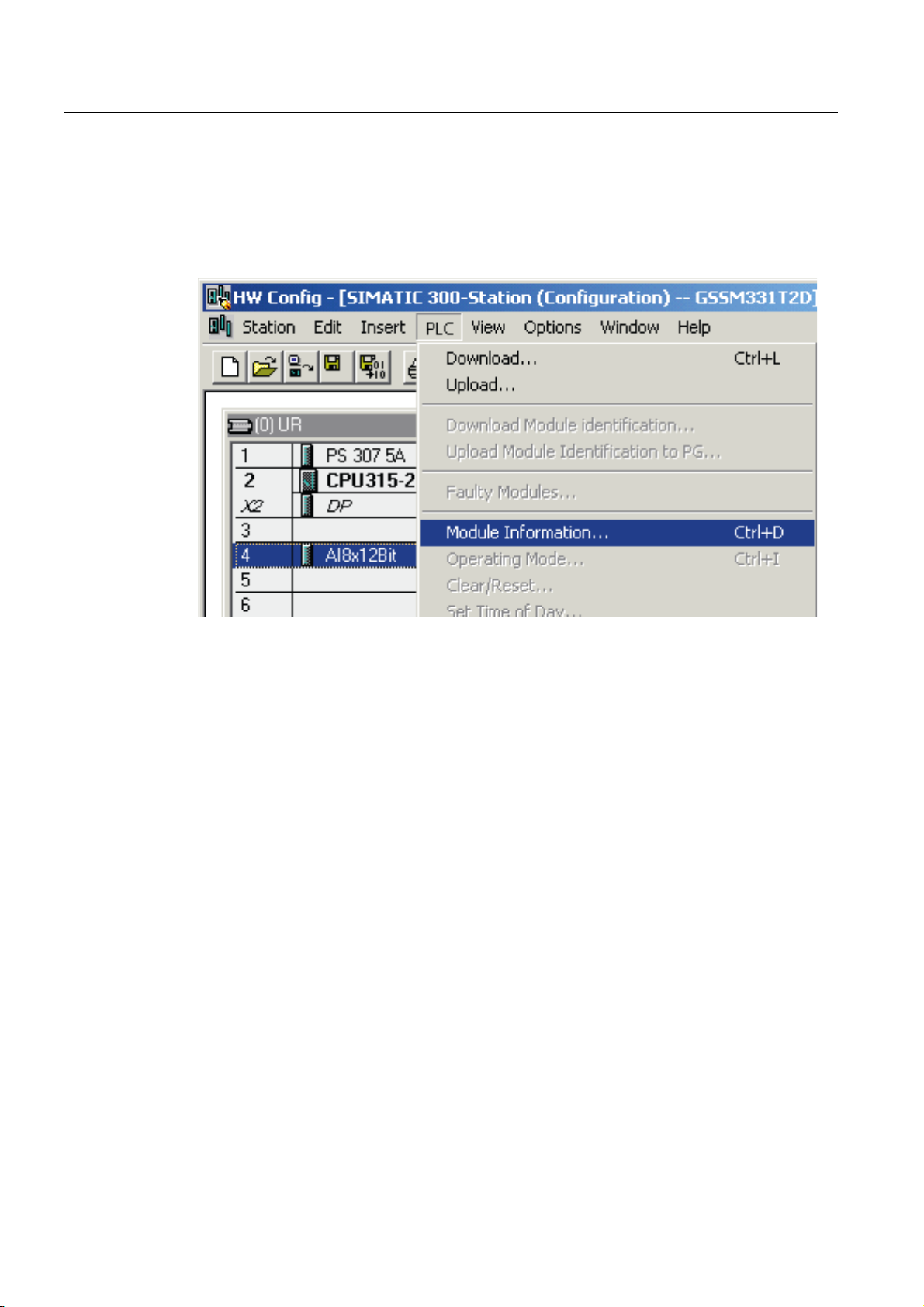
The cause of the error can be determined "online" by requesting the hardware status.
In order to determine the state of module "online", proceed as follows:
Select the SM331 in the hardware configuration. Click the menu command CPU -> Module
Information... in order to perform a hardware diagnostics.
Figure 8-2 Module status
SM331; AI 8x12 Bit Getting Started part 1: 4 -20mA
8-2 Getting Started, 11/2006, A5E00253410-02
Page 63
Diagnostic interrupt
8.2 General diagnostics
8.2 General diagnostics
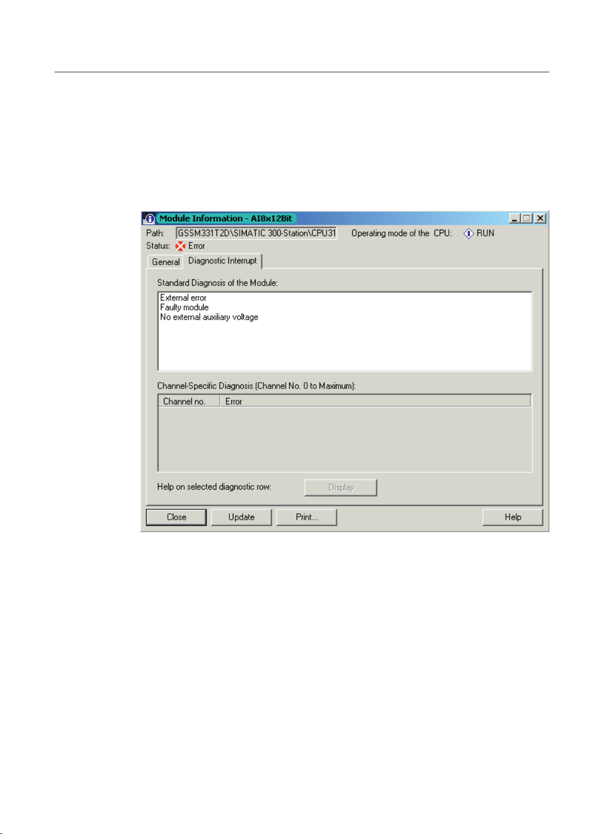
Diagnostic interrupt tab
On the Diagnostic Interrupt tab you will find information for the reported error.
The interrupts are not channel dependent and apply to the entire module.
Figure 8-3 Diagnostics for SM331
SM331; AI 8x12 Bit Getting Started part 1: 4 -20mA
Getting Started, 11/2006, A5E00253410-02
8-3
Page 64

Diagnostic interrupt
8.3 Channel dependent diagnostic interrupts
8.3 Channel dependent diagnostic interrupts
8.3.1 There are five channel dependent diagnostic interrupts
There are five channel dependent diagnostic interrupts:
● Configuration / programming error
● Common mode error
● Wire break
● Underflow
● Overflow
Note
Here we show you only the channel specific diagnostics for the measuring modes 2 or 4-
wire current transducers. Other measuring modes are similar but not described here.
8.3.2 Configuration / programming error
Meaning
The position of the measuring range modules does not match the measuring mode set in the
hardware configuration.
8.3.3 Common mode error
Meaning
The voltage difference Ucm between the inputs (M-) and the common voltage potential of the
measuring circuit (M
In our example, this error cannot occur because M
transducer (fixed potential).
) is too high.
ana
is connected to M for a 2-wire
ana
SM331; AI 8x12 Bit Getting Started part 1: 4 -20mA
8-4 Getting Started, 11/2006, A5E00253410-02
Page 65

Diagnostic interrupt
8.3 Channel dependent diagnostic interrupts
8.3.4 Wire break
Meaning
If wire break detection is enabled for 2-wire transducers, there will be no direct check for a
wire break. The diagnostics instead reacts on the shortfall of the low limit current value.
With 4 to 20 mA current transducer, the diagnostic message “Analog input wire break“ is
shown in the module diagnostics when the current goes below 3.6 mA.
Figure 8-4 Left: Diagnostic message with wire break / Right: Variable table
The display of the analog values shows an underflow (Hex 8000) immediately even if the
current measured is clearly above 1.1185 mA.
Underloading 3.6 mA is only possible if wire break detection has been disabled.
8.3.5 Underflow
Meaning
The display of the analog values shows an underflow immediately even if the current
measured is clearly above 1.1185 mA.
SM331; AI 8x12 Bit Getting Started part 1: 4 -20mA
Getting Started, 11/2006, A5E00253410-02
8-5
Page 66

Diagnostic interrupt
8.3 Channel dependent diagnostic interrupts
8.3.6 Overflow
Meaning
If the current exceeds 22.81 mA, an overflow message stating "Analog in-put measuring
range / High limit exceeded" is displayed.
The display of the analog value (HEX 7FFF) is in the overflow range.
Figure 8-5 Left: Diagnostic message with overflow / Right: Variable table
Note
Disabled channels also have 7FFF hex as the analog display value.
SM331; AI 8x12 Bit Getting Started part 1: 4 -20mA
8-6 Getting Started, 11/2006, A5E00253410-02
Page 67

Hardware interrupt
9.1 Hardware interrupt
Overview
A special feature of the SM331 AI8x12bit is its capability to trigger hardware interrupts. Two
channels (0 and 2) can be correspondingly configured.
Hardware interrupts generally trigger alarm organization blocks in the CPU. In our example,
OB40 is called.
The limit values for hardware interrupts have to be specified in mA.
Example:
You have connected a pressure sensor with a 4-20mA transducer to channel 0. Here the
limit values should be specified in mA and not in Pascal (Pa).
limit values
In order to trigger a hardware interrupt, the limit values have to be within the nominal values
of the measuring mode.
9
Example:
If wire break detection (3.6 mA) is enabled, and you choose 3.5 mA for the low limit value,
this setting is accepted by the system. A hardware interrupt will not be triggered because the
diagnostic alarm is always triggered first.
In our example, 2 channels (sensor 1 and 2) are configured with the following limits:
● Lower limit value 6 mA
● Upper limit value 18 mA
SM331; AI 8x12 Bit Getting Started part 1: 4 -20mA
Getting Started, 11/2006, A5E00253410-02
9-1
Page 68

Hardware interrupt
9.1 Hardware interrupt
Determining functions
If a hardware interrupt occurs, OB40 is called. In the user program of OB40 you can program
the reaction of the automation system to hardware interrupts.
In the example user program, OB40 reads the cause of the hardware interrupt. This can be
found in the temporary variable structure OB40_POINT_ADDR (local words 8 to 11).
/%
Figure 9-1 OB40 start information: In the example, and triggered a hardware interrupt
8SSHUOLPLWYDOXHYLRODWHGFKDQQHO
/%
8SSHUOLPLWYDOXHYLRODWHGFKDQQHO
9LRODWLRQRIWKHOROLPLWDWFKDQQHO
9LRODWLRQRIWKHOROLPLWDWFKDQQHO
In the example, OB40 only transfers LD8 and LD9 into a marker word (MW100). The marker
word is monitored in the existing variable table. You can acknowledge the marker word in
OB1 by setting marker bit M200.0 or by setting it to TRUE in the variable table.
If you supply 5.71 mA with a calibration device to channel 0, you will get the value 0001 hex
for MW100 in the variable table. This means that OB40 was called and channel 0 exceeded
its low limit value (6 mA).
Figure 9-2 Hardware interrupt: Channel 0 exceeded low limit value
SM331; AI 8x12 Bit Getting Started part 1: 4 -20mA
9-2 Getting Started, 11/2006, A5E00253410-02
Page 69

Appendix
A.1 Source of the user program
STL source code
In this section you find the source code of the user program from the example.
You can download the source file directly from the HTML page from which you loaded this
"Getting Started".
DATA_BLOCK DB 1
TITLE =Analog module channel values
VERSION : 1.0
STRUCT
BEGIN
END_DATA_BLOCK
DATA_BLOCK DB 2
TITLE =Current transducer (in mA)
VERSION : 1.0
BEGIN
CH_0 : WORD ; //Channel 0
CH_1 : WORD ; //Channel 1
CH_2 : WORD ; //Channel 2
CH_3 : WORD ; //Channel 3
CH_4 : WORD ; //Channel 4
CH_5 : WORD ; //Channel 5
CH_6 : WORD ; //Channel 6
CH_7 : WORD ; //Channel 7
END_STRUCT ;
CH_0 := W#16#0;
CH_1 := W#16#0;
CH_2 := W#16#0;
CH_3 := W#16#0;
CH_4 := W#16#0;
CH_5 := W#16#0;
CH_6 := W#16#0;
CH_7 := W#16#0;
STRUCT
SE_1 : REAL ; //Sensor 1 current value (mA)
SE_2 : REAL ; //Sensor 2 current value (mA)
SE_3 : REAL ; //Sensor 3 current value (mA)
END_STRUCT ;
.SE_1 := 0.000000e+000;
SE_2 := 0.000000e+000;
SE_3 := 0.000000e+000;
A
SM331; AI 8x12 Bit Getting Started part 1: 4 -20mA
Getting Started, 11/2006, A5E00253410-02
A-1
Page 70

Appendix
A.1 Source of the user program
END_DATA_BLOCK
FUNCTION FC 1 : VOID
TITLE =Conversion of a channel’s raw values in mA
VERSION : 1.0
VAR_INPUT
Raw : WORD ; // Analog value display
END_VAR
VAR_OUTPUT
END_VAR
VAR_TEMP
END_VAR
BEGIN
NETWORK
TITLE = Conversion of raw values in mA
// Only long integers can be converted into REAL format
END_FUNCTION
ORGANIZATION_BLOCK OB 1
TITLE = "Main Program Sweep (Cycle)"
VERSION : 1.0
VAR_TEMP
Current : REAL ; // Current in mA
TDoubleInt : DINT ;
TInt : INT;
L #Raw;
T #TInt;
L
#TInt;
ITD
;
T
#TDoubleInt;
L
#TDoubleInt;
DTR
;
T
#Current;
L
1.728000e+003;
/R
;
T
#Current;
L
4.000000e+000;
+R
;
T
#Current;
OB1_EV_CLASS : BYTE ; //Bits 0-3 = 1 (Coming event),
OB1_SCAN_1 : BYTE ; //1 (Cold restart scan 1 of OB 1),
OB1_PRIORITY : BYTE ; //Priority of OB Execution
OB1_OB_NUMBR : BYTE ; //1 (Organization block 1, OB1)
OB1_RESERVED_1 : BYTE ; //Reserved for system
OB1_RESERVED_2 : BYTE ; //Reserved for system
OB1_PREV_CYCLE : INT; //Cycle time of previous OB1 scan (milliseconds)
OB1_MIN_CYCLE : INT; //Minimum cycle time of OB1 (milliseconds)
OB1_MAX_CYCLE : INT; //Minimum cycle time of OB1 (milliseconds)
OB1_DATE_TIME : DATE_AND_TIME ; //Date and time OB1 started
// HEX value
// Current = --------------// 1728
// !
// ! /
// ! /
// ------- +----- /------ +----
//
// Offset correction
Bits 4-7 = 1 (Event class 1)
3 (Scan 2-n of OB 1)
/
4 20
SM331; AI 8x12 Bit Getting Started part 1: 4 -20mA
A-2 Getting Started, 11/2006, A5E00253410-02
Page 71

Appendix
A.1 Source of the user program
END_VAR
BEGIN
NETWORK
TITLE =Read channels
// Channel values 0 to 7 are loaded and stored in DB1 (channel values)
NETWORK
TITLE = Conversion
// Conversion of the channel’s raw data into current values (mA)
NETWORK
TITLE = Reset hardware interrupt
// Even though the hardware interrupt was reset by the hardware upon terminating OB40
// the value of the hardware interrupt must be reset manually
L PEW 256;
T DB1.DBW 0;
L PEW 258;
T DB1.DBW 2;
L PEW 260;
T DB1.DBW 4;
L PEW 262;
T DB1.DBW 6;
L PEW 264;
T DB1.DBW 8;
L PEW 266;
T DB1.DBW 10;
L PEW 268;
T DB1.DBW 12;
L PEW 270;
T DB1.DBW 14;
CALL FC 1 (
Raw
Current
CALL FC 1 (
Raw
Current
CALL FC 1 (
Raw
Current
//Channel 0
//Channel 1
//Channel 2
//Channel 3
//Channel 4
//Channel 5
//Channel 6
//Channel 7
:= DB1.DBW 0,
:= DB2.DBD 0);
:= DB1.DBW 4,
:= DB2.DBD 4);
:= DB1.DBW 6,
:= DB2.DBD 8);
SM331; AI 8x12 Bit Getting Started part 1: 4 -20mA
Getting Started, 11/2006, A5E00253410-02
A-3
Page 72

Appendix
A.1 Source of the user program
NETWORK
TITLE =The End
END_ORGANIZATION_BLOCK
ORGANIZATION_BLOCK OB 40
TITLE = "Hardware Interrupt"
// Processing OB40_POINT_ADDR (L8 to L11)
//
//L8 High limit value exceeded
//L9 Low limit value exceeded
VERSION : 1.0
VAR_TEMP
OB40_EV_CLASS : BYTE ; //Bits 0-3 = 1 (Coming event),
OB40_STRT_INF : BYTE ; //16#41 (OB 40 has started)
OB40_PRIORITY : BYTE ; //Priority of OB Execution
OB40_OB_NUMBR : BYTE ; //40 (Organization block 40, OB40)
OB40_RESERVED_1 : BYTE ; //Reserved for system
OB40_IO_FLAG : BYTE ; //16#54 (input module), 16#55 (output module)
OB40_MDL_ADDR : WORD ; //Base address of module initiating interrupt
OB40_POINT_ADDR : DWORD ; //Interrupt status of the module
OB40_DATE_TIME : DATE_AND_TIME ; //Date and time OB40 started
U
SPBN
L
SSI
T
lbl0: NOP
BE;
M
lbl0;
MW
4;
MW
0;
200.0;
100;
100;
Bits 4-7 = 1 (Event class 1)
END_VAR
BEGIN
NETWORK
TITLE =Sensor 1 (Channel 0): Lower limit value
L001;
NETWORK
TITLE =Sensor 1 (Channel 0): Upper limit value
U L 9.0; // Channel 0 low limit value
SPBNB L001;
L W#16#1;
L MW 100;
OW ;
T MW 100;
NOP 0;
U L 8.0; // Channel 0 upper limit value
SPBNB L002;
L W#16#2;
L MW 100;
OW ;
T MW 100;
SM331; AI 8x12 Bit Getting Started part 1: 4 -20mA
A-4 Getting Started, 11/2006, A5E00253410-02
Page 73

Appendix
A.1 Source of the user program
L002:
NETWORK
TITLE =Sensor 2 (Channel 2): Lower limit value
L003:
NETWORK
TITLE =Sensor 2 (Channel 2): Upper limit value
L004:
NETWORK
TITLE =Sensor 3 (Channel 3): Lower limit value
// Only for demonstration purposes. Channel 3 has now hardware interrupt capabilities
L005:
NETWORK
TITLE =Sensor 3 (Channel 3): Upper limit value
// Only for demonstration purposes. Channel 3 has now hardware interrupt capabilities
L006:
END_ORGANIZATION_BLOCK
NOP 0;
U L 9.2; // Channel 2 low limit value
SPBNB L003;
L W#16#4;
L MW 100;
OW ;
T MW 100;
NOP 0;
U L 8.2; // Channel 2 upper limit value
SPBNB L004;
L W#16#8;
L MW 100;
OW ;
T MW 100;
NOP 0;
U L 9.3; // Channel 3 low limit value
SPBNB L005;
L W#16#10;
L MW 100;
OW ;
T MW 100;
NOP 0;
U L 8.3; // Channel 3 upper limit value
SPBNB L006;
L W#16#20;
L MW 100;
OW ;
T MW 100;
NOP 0;
SM331; AI 8x12 Bit Getting Started part 1: 4 -20mA
Getting Started, 11/2006, A5E00253410-02
A-5
Page 74

Appendix
A.1 Source of the user program
SM331; AI 8x12 Bit Getting Started part 1: 4 -20mA
A-6 Getting Started, 11/2006, A5E00253410-02
Page 75

Index
2
2-Wire current transducer
wiring principle, 5-4
4
4-Wire current transducer
wiring principle, 5-5
A
Add
SIMATIC components, 6-8
Adding SIMATIC components, 6-8
Analog module
Characteristics, 4-5
Configuring, 6-10
Inserting, 6-9
Installing, 4-3
The required hardware and software, 2-1
Wiring, 5-4, 5-5
Analog value representation, 7-8
in Current Measuring Ranges 4 to 20 mA, 7-8
Assigning
Project name, 6-5
B
Basic processing time, 6-12
Bus connectors
Insert, 4-2
C
Calling
Configuration, 6-11
Hardware configuration, 6-7
Channel group
Not used, 5-7
Characteristics
Analog module, 4-5
Check
Line voltage, 5-3
Clear / Reset, 6-13
Common mode error, 8-4
Components
SM331, 4-4
Components of the Product
SM331 modules, 4-4
Configuration
Calling, 6-11
Configuration / programming error, 8-4
Configuration language
STL, 6-4
Configuring
Analog module, 6-10
CPU 315-2DP, 6-1
Hardware configuration, 6-7
with SIMATIC Manager, 6-1
Connect
CPU with programming device, 6-13
Connecting-up
Errors, 5-8
test, 5-8
Control
Values, 7-7
Control value, 7-7
Converting
digital values to analog values, 7-8
CPU
CPU with programming device, 6-13
Installing, 4-2
Selecting, 6-3
start, 6-16
Wiring the power supply, 5-2
CPU 315-2DP
configuring, 6-1
Create
STEP 7 project, 6-1
User Program, 6-18
Current transducers
wiring principle, 5-4
SM331; AI 8x12 Bit Getting Started part 1: 4 -20mA
Getting Started, 11/2006, A5E00253410-02
Index-1
Page 76

Index
D
Define the basic user program
Defining, 6-4
Defining
Defining the basic user program, 6-4
Functions in event of hardware interrupts, 9-2
Delete
Micro memory card, 6-13
Diagnostic functionality, 5-7
Diagnostic information
read from a PG, 8-1
Diagnostics message
channel dependent, 8-4
General, 8-3
Digital value
convert to analog value, 7-8
Displays
Errors, 8-3
Download
source code, A-1
Source file, 6-18
Downloading
Download system data and user program into the
automation system, 7-1
Hardware configuration, 6-14
Downloading system data and user program
Downloading to automation system, 7-1
E
Hardware configuration
calling, 6-7
Configuring, 6-7
Downloading, 6-14
Finishing, 6-12
Hardware fault
find, 8-2
Hardware interrupt
limit values, 9-1
Hardware interrupt, 6-12, 9-1
I
Importing
Source file, 6-19
Insert
Bus connectors, 4-2
Inserting
Analog module, 6-9
Installation
Analog module, 4-3
CPU, 4-2
Front connector, 4-8
Plant, 4-1
Power supply, 4-2
SM331, 4-8
Integration time, 6-12
Interference frequency, 6-12
Interference frequency suppression, 6-12
Error display, 8-3
Errors
Connecting-up, 5-8
F
Fill out
Variable table, 7-4
Finish
Hardware configuration, 6-12
Front connector
Installing, 4-8
L
Labeling strips for modules, 7-2
LEDs, 5-8
green, 6-16
red, 8-1
limit values
Hardware interrupt, 9-1
Line frequency, 6-12
Line voltage
Changing, 5-3
Check, 5-3
Load power supply
Selecting, 6-8
H
Hardware and software
for analog modules, 2-1
Hardware catalog
opening, 6-8
SM331; AI 8x12 Bit Getting Started part 1: 4 -20mA
Index-2 Getting Started, 11/2006, A5E00253410-02
M
Measuring range modules, 6-12
Positioning, 4-7
Positions, 4-6
Page 77

Index
Micro memory card
Deleting, 6-13
Monitoring
Values, 7-6
Mounting rail
screw, 4-1
O
OB82, 6-17
Organization blocks
Selecting, 6-4
Overflow, 8-6
P
Parameters
set, 6-10
Plant
Installing, 4-1
Position
Measuring range modules, 4-7
Positions
Measuring range modules, 4-6
Power supply
Installing, 4-2
screw, 4-2
Wiring the CPU, 5-2
Powering-up, 6-13
Process Acknowledgement, 7-7
Project name
Assigning, 6-5
R
Sensor values
Visualize, 7-3
Settings
Parameters, 6-10
test, 6-13
SIMATIC Manager, 6-1
Hardware configuration, 6-7
start, 6-1
SM331
Components, 4-4
Installing, 4-8
SM331 Front connector
Wiring, 5-7
SM331 modules
Components of the Product, 4-4
Smart Label, 7-2
source code
Compiling, 6-22
Download, A-1
User Program, A-1
Source code editor, 6-22
Source file
Download, 6-18
Import, 6-19
Starting
CPU, 6-16
SIMATIC Manager, 6-1
STEP 7 project
Creating, 6-1
STEP 7 user program, 6-17
Tasks, 6-17
STL, 6-4
STL source code, A-1
Structure
User Program, 6-17
Reading out
Read diagnostic information from a PG, 8-1
Resolution, 6-12
S
Screw
Mounting rail, 4-1
Power supply, 4-2
Selecting
CPU, 6-3
Load power supply, 6-8
Organization blocks, 6-4
Target addresses, 6-15
SM331; AI 8x12 Bit Getting Started part 1: 4 -20mA
Getting Started, 11/2006, A5E00253410-02
T
Target addresses
Selecting, 6-15
Terminal
Transducer, 4-6
Test
Connecting-up, 5-8
Settings, 6-13
Testing
User Program, 7-1
Transducer
Terminal, 4-6
Type of measurement, 6-12
Index-3
Page 78

Index
U
Underflow, 8-5
User Program
Creating, 6-18
source code, A-1
Structure, 6-17
Testing, 7-1
V
Values
Controlling, 7-7
Monitor, 7-6
Variable description, 7-5
Variable table
Fill out, 7-4
Visualize
Sensor values, 7-3
W
Wire break, 8-5
Wiring
Analog module, 5-4, 5-5
SM331 Front connector, 5-7
Wiring the power supply and CPU, 5-2
Wiring principle
2-Wire current transducer, 5-4
4-Wire current transducer, 5-5
Current transducers, 5-4
Wizard "New Project...", 6-1
SM331; AI 8x12 Bit Getting Started part 1: 4 -20mA
Index-4 Getting Started, 11/2006, A5E00253410-02
 Loading...