

Siemens Simatic S7-300 CPU 31xC, Simatic S7-300 CPU 312C, Simatic S7-300 CPU 314C-2 DP, Simatic S7-300 CPU 313C-2 DP, Simatic S7-300 CPU 314C-2 PtP Installation And Operating Instructions Manual
...Page 1

SIMATIC
S7-300, CPU 31xC and CPU 31x:
Installation
Operating Instructions
Preface
Guide to the S7-300
documentation
Installation Order
S7-300 components
Configuring
Installing
Wiring
1
2
3
4
5
6
Addressing
Commissioning
Maintenance
Debugging functions, diagnostics and troubleshooting
Appendix
7
8
9
10
A
This manual is part of the documentation package
with the order number: 6ES7398-8FA10-8BA0
Edition 08/2004
A5E00105492-05
Page 2

Safety Guidelines
This manual contains notices which you should observe to ensure your own personal safety as well as to avoid
property damage. The notices referring to your personal safety are highlighted in the manual by a safety alert
symbol, notices referring to property damage only have no safety alert symbol.
Danger
indicates an imminently hazardous situation which, if not avoided, will result in death or serious injury.
Warning
indicates a potentially hazardous situation which, if not avoided, could result in death or serious injury.
Caution
used with the safety alert symbol indicates a potentially hazardous situation which, if not avoided, may
result in minor or moderate injury.
Caution
used without safety alert symbol indicates a potentially hazardous situation which, if not avoided, may
result in property damage.
Notice
used without the safety alert symbol indicates a potential situation which, if not avoided, may result in
an undesirable result or state.
If more than one degree of danger is present, the warning notice representing the highest degree of danger will
be used. A notice warning of injury to persons with a safety alert symbol may also include a warning relating to
property damage.
Qualified Personnel
The device/system may only be set up and operated in conjunction with this documentation. Only qualified
personnel should be allowed to install and work on the equipment. Qualified persons are defined as persons who
are authorized to commission, to earth, and to tag circuits, equipment and systems in accordance with
established safety practices and standards.
Intended Use
Please note the following:
Warning
This device and its components may only be used for the applications described in the catalog or
technical description, and only in connection with devices or components from other manufacturers
approved or recommended by Siemens.
This product can only function correctly and safely if it is transported, stored, set up and installed
correctly, and operated and maintained as recommended.
Trademarks
All designations marked with ® are registered trademarks of Siemens AG. Other designations in this
documentation might be trademarks which, if used by third parties for their purposes, might infringe upon the
rights of the proprietors.
Copyright Siemens AG ,2004.All rights reserved
Reproduction, transmission or use of this document or its contents is not permitted without
express written authority. Offenders will be liable for damages. All rights, including rights
created by patent grant or registration of a utility model or design, are reserved.
Siemens AG
Automation and Drives Group
P.O. Box 4848, D-90327 Nuremberg (Germany)
Siemens Aktiengesellschaft Order No. A5E00105492-05
Disclaimer of Liability
We have checked the contents of this manual for agreement with the hardware and
software described. Since deviations cannot be precluded entirely, we cannot guarantee
full agreement. However, the data in the manual are reviewed regularly, and any
necessary corrections will be included in subsequent editions. Suggestions for
improvement are welcomed.
Siemens AG 2004
Technical data subject to change
Page 3

Preface
Purpose of the manual
This manual contains all the information you need to configure, install, wire, address and
commission an S7-300.
In addition, you will become familiar with the tools you can use to diagnose and eliminate
errors in hardware and software.
Basic knowledge
To understand this manual, you require a general knowledge of automation engineering. You
should also be accustomed to working with STEP 7 basic software. For further information,
refer to the Programming with STEP 7 V5.3 manual.
Area of application
Note
The special features of the 315F-2 DP and CPU 317F-2 DP CPUs are described in their
Product Information, available on the Internet at
http://www.siemens.com/automation/service&support, article ID 17015818.
Order number
CPU designation
CPU 312C 6ES7312-5BD01-0AB0 V2.0.0 01
CPU 313C 6ES7313-5BE01-0AB0 V2.0.0 01
CPU 313C-2 PtP 6ES7313-6BE01-0AB0 V2.0.0 01
CPU 313C-2 DP 6ES7313-6CE01-0AB0 V2.0.0 01
CPU 314C-2 PtP 6ES7314-6BF01-0AB0 V2.0.0 01
CPU 314C-2 DP
CPU 312 6ES7312-1AD10-0AB0 V2.0.0 01
CPU 314 6ES7314-1AF10-0AB0 V2.0.0 01
CPU 315-2 DP 6ES7315-2AG10-0AB0 V2.0.0 01
CPU 315-2-PN/DP 6ES7315-2EG10-0AB0 V2.3.0 01
CPU 317-2 DP 6ES7317-2AJ10-0AB0 V2.1.0 01
CPU 317-2 PN/DP
CPU 31xC
6ES7314-6CF01-0AB0 V2.0.0 01
CPU 31x
6ES7317-2EJ10-0AB0 V2.3.0 01
as of version CPU Convention:
Firmware Hardware
S7-300, CPU 31xC and CPU 31x: Installation
Operating Instructions, Edition 08/2004, A5E00105492-05
iii
Page 4

Preface
Approvals
CE label
Note
There you can obtain the descriptions of all current modules.
For new modules, or modules of a more recent version, we reserve the right to include a
Product Information containing latest information.
The SIMATIC S7-300 product series has the following approvals:
• Underwriters Laboratories, Inc.: UL 508 (Industrial Control Equipment)
• Canadian Standards Association: CSA C22.2 No. 142, (Process Control Equipment)
• Factory Mutual Research: Approval Standard Class Number 3611
The SIMATIC S7-300 product series satisfies the requirements and safety specifications of
the following EU Directives:
• EU Directive 73/23/EC "Low-voltage directive"
• EU Directive 89/336/EWE "EMC directive"
C tick mark
Standards
The SIMATIC S7-300 product series is compliant with AS/NZS 2064 (Australia).
The SIMATIC S7-300 product series is compliant with IEC 61131-2.
S7-300, CPU 31xC and CPU 31x: Installation
iv Operating Instructions, Edition 08/2004, A5E00105492-05
Page 5

Preface
Documentation classification
This manual is part of the S7-300 documentation package.
Name of the manual Description
Manual
• 31xC and 31x CPUs, technical data
Reference Manual
• CPU data: CPU 312 IFM – 318-2 DP
YOU ARE READING the Manual
• S7-300, CPU 31xC and CPU 31x: Installation
Installation Manual
• S7-300 Automation System: Installation: CPU
312 IFM – 318-2 DP
System Manual
PROFINET System Overview
Programming Manual
From PROFIBUS DP to PROFINET I/O
Manual
• CPU 31xC: Technological functions
• Examples
Reference Manual
• S7-300 Automation System: Module data
Instruction List
• CPU 312 IFM – 318-2 DP
• CPU 31xC and CPU 31x
Getting Started
The following Getting Started editions are available
as a collective volume:
• CPU 31x: Commissioning
• CPU 31xC: Commissioning
• CPU 31xC: Positioning with analog output
• CPU 31xC: Positioning with digital output
• CPU 31xC: Counting
• CPU 31xC: Rules
• CPU 31xC: PtP communication
• CPU 31x-2 PN/DP: Commissioning a
PROFINET I/O subnet
Control and display elements, communication,
memory concept, cycle and response times,
technical data
Control and display elements, communication,
memory concept, cycle and response times,
technical data
Configuration, installation, wiring, addressing,
commissioning, maintenance and the test
functions, diagnostics and troubleshooting.
Configuration, installation, wiring, addressing,
commissioning, maintenance and the test
functions, diagnostics and troubleshooting.
Basic information on PROFINET:
Network components, data exchange and
communication, PROFINET I/O, Component
based Automation, application example of
PROFINET I/O and Component based
Automation
Guideline for the migration from PROFIBUS DP
to PROFINET I/O.
Description of the various technological
functions of positioning and counting. PtP
communication, rules
The CD contains examples of the technological
functions
Descriptions of the functions and technical data
of signal modules, power supply modules and
interface modules.
List of CPU instruction resources and the
relevant execution times. List of executable
blocks.
The example used in this Getting Started
guides you through the various steps in
commissioning required to obtain a fully
functional application.
S7-300, CPU 31xC and CPU 31x: Installation
Operating Instructions, Edition 08/2004, A5E00105492-05
v
Page 6

Preface
Additional information required:
Name of the manual Description
Reference Manual
System software for S7-300/400 system and standard
functions
Manual
SIMATIC NET: Twisted Pair and Fiber-Optic Networks
Manual
Component-based Automation: Configuring systems with
SIMATIC iMap
Manual
Programming with STEP 7 V5.3
Manual
SIMATIC communication
Description of the SFCs, SFBs and OBs.
This manual is part of the STEP 7
documentation package. For further
information, refer to the STEP 7 Online
Help.
Description of Industrial Ethernet
networks, network configuration,
components, installation guidelines for
networked automation systems in
buildings, etc.
Description of the engineering software
iMAP
Programming with STEP 7
Basics, services, networks,
communication functions, connecting
PGs/OPs, engineering and configuring in
STEP 7.
S7-300 documentation package: Additional documentation
Recycling and Disposal
The devices described in this manual can be recycled, because their components contain a
minimum of harmful substances. For environment-friendly recycling and disposal of your old
equipment, contact a certified disposal facility for electronic scrap.
S7-300, CPU 31xC and CPU 31x: Installation
vi Operating Instructions, Edition 08/2004, A5E00105492-05
Page 7

Table of contents
Preface ......................................................................................................................................................iii
1 Guide to the S7-300 documentation ....................................................................................................... 1-1
2 Installation Order .................................................................................................................................... 2-1
3 S7-300 components................................................................................................................................ 3-1
3.1 Example of an S7-300 configuration..........................................................................................3-1
3.2 Overview of the vital modules of an S7-300 .............................................................................. 3-2
4 Configuring ............................................................................................................................................. 4-1
4.1 Overview .................................................................................................................................... 4-1
4.2 Basic engineering principles ...................................................................................................... 4-1
4.3 Component dimensions ............................................................................................................. 4-4
4.4 Required clearances .................................................................................................................. 4-6
4.5 Arrangement of modules on a single rack ................................................................................. 4-7
4.6 Distribution of modules to several racks ....................................................................................4-8
4.7 Selection and installation of cabinets....................................................................................... 4-11
4.8 Example: Selecting a cabinet................................................................................................... 4-14
4.9 Electrical assembly, protective measures and grounding ....................................................... 4-15
4.9.1 Grounding concept and overall structure................................................................................. 4-15
4.9.2 Installing an S7-300 with grounded reference potential .......................................................... 4-16
4.9.3 Configuring an S7-300 with ungrounded reference potential (not CPU 31xC)........................ 4-17
4.9.4 Modules with isolated or common potential?........................................................................... 4-19
4.9.5 Grounding measures ............................................................................................................... 4-21
4.9.6 Overview: Grounding ............................................................................................................... 4-24
4.10 Selecting the Load Power Supply............................................................................................ 4-26
4.11 Planning subnets ..................................................................................................................... 4-28
4.11.1 Overview .................................................................................................................................. 4-28
4.11.2 Configuring MPI and PROFIBUS subnets ............................................................................... 4-30
4.11.2.1 Overview .................................................................................................................................. 4-30
4.11.2.2 Basic principles of MPI and PROFIBUS subnets .................................................................... 4-30
4.11.2.3 Multi-Point Interface (MPI) ....................................................................................................... 4-33
4.11.2.4 PROFIBUS DP interface.......................................................................................................... 4-34
4.11.2.5 Network components of MPI/DP and cable lengths ................................................................ 4-35
4.11.2.6 Cable lengths of MPI and PROFIBUS subnets ....................................................................... 4-40
4.11.3 Configuring PROFINET subnets.............................................................................................. 4-45
4.11.3.1 Overview .................................................................................................................................. 4-45
4.11.3.2 PROFINET nodes .................................................................................................................... 4-45
4.11.3.3 Integration of field bus systems in PROFINET ........................................................................ 4-48
4.11.3.4 PROFINET IO and PROFINET CBA ....................................................................................... 4-49
4.11.3.5 PROFINET cable lengths and network expansion .................................................................. 4-54
S7-300, CPU 31xC and CPU 31x: Installation
Operating Instructions, Edition 08/2004, A5E00105492-05
vii
Page 8

Table of contents
4.11.3.6 Connectors and other components for Ethernet...................................................................... 4-56
4.11.3.7 Example of a PROFINET Subnet ............................................................................................4-57
4.11.3.8 Example of a PROFINET IO system........................................................................................ 4-59
4.11.4 Routed network transitions....................................................................................................... 4-60
4.11.5 Point-to-point (PtP)................................................................................................................... 4-62
4.11.6 Actuator/sensor interface (ASI) ................................................................................................ 4-63
5 Installing .................................................................................................................................................5-1
5.1 Installing an S7-300 ................................................................................................................... 5-1
5.2 Installing the mounting rail ......................................................................................................... 5-3
5.3 Mounting modules onto the rail.................................................................................................. 5-7
5.4 Labeling the modules................................................................................................................. 5-9
6 Wiring ..................................................................................................................................................... 6-1
6.1 Requirements for wiring the S7-300 ..........................................................................................6-1
6.2 Bonding the Protective Conductor to the Mounting Rail ............................................................ 6-3
6.3 Adjusting the Power Supply Module to local Mains Voltage...................................................... 6-4
6.4 Wiring the Power Supply Module and the CPU ......................................................................... 6-5
6.5 Wiring Front Connectors ............................................................................................................ 6-7
6.6 Plugging the front connectors into modules............................................................................. 6-10
6.7 Labeling the module I/O........................................................................................................... 6-11
6.8 Connecting shielded cables to the shielding contact element ................................................. 6-12
6.9 Wiring the MPI / PROFIBUS DP bus connectors..................................................................... 6-15
6.9.1 Wiring the bus connector ......................................................................................................... 6-15
6.9.2 Setting the terminating resistor on the bus connector ............................................................. 6-16
6.10 RJ45 Ethernet connector ......................................................................................................... 6-17
7 Addressing.............................................................................................................................................. 7-1
7.1 Slot-specific addressing of modules .......................................................................................... 7-1
7.2 User-specific addressing of modules.........................................................................................7-3
7.2.1 User-specific addressing of modules ......................................................................................... 7-3
7.2.2 Addressing digital modules ........................................................................................................ 7-3
7.2.3 Addressing analog modules....................................................................................................... 7-5
7.2.4 Addressing the integrated I/Os of CPU 31xC ............................................................................ 7-6
7.3 Consistent data .......................................................................................................................... 7-8
8 Commissioning ....................................................................................................................................... 8-1
8.1 Overview .................................................................................................................................... 8-1
8.2 Commissioning procedure ......................................................................................................... 8-1
8.2.1 Procedure: Commissioning the hardware.................................................................................. 8-1
8.2.2 Procedure: Software commissioning .........................................................................................8-3
8.3 Commissioning check list........................................................................................................... 8-5
8.4 Commissioning the Modules...................................................................................................... 8-7
8.4.1 Inserting/Replacing a Micro Memory Card (MMC)..................................................................... 8-7
8.4.2 Initial power on ........................................................................................................................... 8-9
8.4.3 CPU memory reset by means of mode selector switch ............................................................. 8-9
8.4.4 Formatting the Micro Memory Card (MMC) ............................................................................. 8-12
8.4.5 Connecting the programming device (PG)............................................................................... 8-13
S7-300, CPU 31xC and CPU 31x: Installation
viii Operating Instructions, Edition 08/2004, A5E00105492-05
Page 9

Table of contents
8.4.5.1 Connecting a PG/PC to the integrated PROFINET interface of the CPU 31x-2 PN/DP ......... 8-13
8.4.5.2 Connecting the PG to a node................................................................................................... 8-14
8.4.5.3 Connecting the PG to several nodes ....................................................................................... 8-15
8.4.5.4 Using the PG for commissioning or maintenance.................................................................... 8-16
8.4.5.5 Connecting a PG to ungrounded MPI nodes (not CPU 31xC) ................................................ 8-17
8.4.6 Starting SIMATIC Manager...................................................................................................... 8-18
8.4.7 Monitoring and modifying I/Os ................................................................................................. 8-19
8.5 Commissioning PROFIBUS DP............................................................................................... 8-23
8.5.1 Commissioning PROFIBUS DP............................................................................................... 8-23
8.5.2 Commissioning the CPU as DP master................................................................................... 8-24
8.5.3 Commissioning the CPU as DP Slave..................................................................................... 8-27
8.5.4 Direct data exchange ............................................................................................................... 8-33
8.6 Commissioning PROFINET IO ................................................................................................ 8-34
8.6.1 Requirements........................................................................................................................... 8-34
8.6.2 Configuring and commissioning the PROFINET IO system .................................................... 8-35
9 Maintenance ........................................................................................................................................... 9-1
9.1 Overview .................................................................................................................................... 9-1
9.2 Backup of firmware to Micro Memory Card (MMC) ................................................................... 9-1
9.3 Updating the firmware from MMC..............................................................................................9-3
9.4 Online (via networks) update of CPU FW V2.2.0 or higher. ...................................................... 9-4
9.5 Backup of project data to a Micro Memory Card (MMC) ........................................................... 9-5
9.6 Module installation / removal ..................................................................................................... 9-6
9.7 Digital output module AC 120/230 V: Changing fuses ............................................................ 9-11
10 Debugging functions, diagnostics and troubleshooting......................................................................... 10-1
10.1 Overview .................................................................................................................................. 10-1
10.2 Overview: Debugging functions ............................................................................................... 10-1
10.3 Overview: Diagnostics ............................................................................................................. 10-4
10.4 Diagnostic Options with STEP 7.............................................................................................. 10-7
10.5 Network Infrastructure Diagnostics (SNMP) ............................................................................ 10-8
10.6 Diagnostics using status and error LEDs................................................................................. 10-9
10.6.1 Introduction .............................................................................................................................. 10-9
10.6.2 Status and error displays of all CPUs .................................................................................... 10-10
10.6.3 Evaluating the SF LED in case of software errors ................................................................. 10-11
10.6.4 Evaluating the SF LED in case of hardware errors................................................................ 10-13
10.6.5 Status and Error Indicators: CPUs with DP Interface ............................................................ 10-14
10.6.6 Status displays: CPUs with PN Interface............................................................................... 10-16
10.7 Diagnostics of DP CPUs ........................................................................................................ 10-18
10.7.1 Diagnostics of DP CPUs operating as DP Master ................................................................. 10-18
10.7.2 Reading out slave diagnostic data......................................................................................... 10-21
10.7.3 Interrupts on the DP Master................................................................................................... 10-25
10.7.4 Structure of slave diagnostic data when the CPU is operated as Intelligent Slave............... 10-27
10.8 Diagnostics of PN CPUs ........................................................................................................ 10-34
S7-300, CPU 31xC and CPU 31x: Installation
Operating Instructions, Edition 08/2004, A5E00105492-05
ix
Page 10

Table of contents
A Appendix.................................................................................................................................................A-1
A.1 General Rules and Regulations for S7-300 Operation ..............................................................A-1
A.2 Protection against electromagnetic interference........................................................................ A-3
A.2.1 Basic Points for EMC-compliant system installations ................................................................A-3
A.2.2 Five basic rules for securing EMC .............................................................................................A-5
A.2.2.1 1. Basic rule for ensuring EMC ..................................................................................................A-5
A.2.2.2 2. Basic rule for ensuring EMC ..................................................................................................A-5
A.2.2.3 3. Basic rule for ensuring EMC ..................................................................................................A-6
A.2.2.4 4. Basic rule for ensuring EMC ..................................................................................................A-6
A.2.2.5 5. Basic rule for ensuring EMC ..................................................................................................A-7
A.2.3 EMC-compliant installation of PLCs...........................................................................................A-7
A.2.4 Examples of an EMC-compliant installation: Cabinet installation.............................................. A-9
A.2.5 Examples of an EMC-compliant installation: Wall mounting....................................................A-10
A.2.6 Cable shielding.........................................................................................................................A-12
A.2.7 Equipotential bonding...............................................................................................................A-14
A.2.8 Cable routing inside buildings ..................................................................................................A-16
A.2.9 Outdoor routing of cables.........................................................................................................A-18
A.3 Lightning and Surge Voltage Protection ..................................................................................A-18
A.3.1 Overview ..................................................................................................................................A-18
A.3.2 Lightning protection zone concept ...........................................................................................A-19
A.3.3 Rules for the transition point between lightning protection zones 0 <-> 1 ...............................A-21
A.3.4 Rules for the transition point between lightning protection zones 1 <-> 2 and higher.............A-22
A.3.5 Example: Surge protection circuit for networked S7-300 PLCs...............................................A-26
A.3.6 How to Protect Digital Output Modules against Inductive Surge Voltage................................A-28
A.4 Safety of Electronic Control Equipment ...................................................................................A-30
Glossary ..................................................................................................................................... Glossary-1
Index................................................................................................................................................ Index-1
S7-300, CPU 31xC and CPU 31x: Installation
x Operating Instructions, Edition 08/2004, A5E00105492-05
Page 11

Table of contents
Tables
Table 1-1
Ambient influence on the automation system (AS).................................................................... 1-1
Table 1-2 Galvanic isolation....................................................................................................................... 1-1
Table 1-3 Communication between sensors/actuators and the PLC......................................................... 1-2
Table 1-4 The use of local and distributed I/O ........................................................................................... 1-2
Table 1-5 Configuration consisting of the Central Unit (CU) and Expansion Modules (EMs) ................... 1-2
Table 1-6 CPU performance ...................................................................................................................... 1-3
Table 1-7 Communication .......................................................................................................................... 1-3
Table 1-8 Software..................................................................................................................................... 1-3
Table 1-9 Supplementary features............................................................................................................. 1-4
Table 3-1 S7-300 components:.................................................................................................................. 3-2
Table 4-1 Mounting rails - Overview .......................................................................................................... 4-4
Table 4-2 Module width.............................................................................................................................. 4-4
Table 4-3 Shielding terminals - Overview ..................................................................................................4-5
Table 4-4 Interface modules - Overview ....................................................................................................4-8
Table 4-5 Cabinet types ........................................................................................................................... 4-13
Table 4-6 Cabinet selection ..................................................................................................................... 4-15
Table 4-7 VDE specifications for the installation of a PLC system .......................................................... 4-16
Table 4-8 Measures for protective grounding .......................................................................................... 4-22
Table 4-9 Connecting the load voltage reference potential ..................................................................... 4-23
Table 4-10 Connecting the load voltage reference potential ..................................................................... 4-24
Table 4-11 Connecting the load voltage reference potential ..................................................................... 4-25
Table 4-12 Features of load power supply units ........................................................................................ 4-26
Table 4-13 Subnet nodes........................................................................................................................... 4-31
Table 4-14 MPI/PROFIBUS DP addresses................................................................................................ 4-31
Table 4-15 MPI addresses of CPs/FMs in an S7-300 system ................................................................... 4-32
Table 4-16 Operating modes for CPUs with two DP interfaces................................................................. 4-34
Table 4-17 Permissible cable length of a segment on the MPI subnet...................................................... 4-35
Table 4-18 Permissible cable length of a segment on the PROFIBUS subnet.......................................... 4-35
Table 4-19 Lengths of stub cables per segment........................................................................................ 4-36
Table 4-20 PG patch cord .......................................................................................................................... 4-36
Table 4-21 Available bus cables ................................................................................................................ 4-37
Table 4-22 Properties of PROFIBUS cables.............................................................................................. 4-37
Table 4-23 Marginal conditions for wiring interior bus cables.................................................................... 4-38
Table 4-24 Bus connector .......................................................................................................................... 4-38
Table 4-25 Data for twisted-pair patch cables............................................................................................ 4-55
Table 5-1 Module accessories ................................................................................................................... 5-2
S7-300, CPU 31xC and CPU 31x: Installation
Operating Instructions, Edition 08/2004, A5E00105492-05
xi
Page 12

Table of contents
Table 5-2 Installation tools and materials................................................................................................... 5-3
Table 5-3 Mounting holes for rails.............................................................................................................. 5-5
Table 5-4 Slot numbers for S7 modules.....................................................................................................5-9
Table 6-1 Wiring accessories..................................................................................................................... 6-1
Table 6-2 Tools and material for wiring...................................................................................................... 6-1
Table 6-3 Wiring conditions for PS and CPU ............................................................................................. 6-2
Table 6-4 Wiring conditions for front connectors........................................................................................ 6-2
Table 6-5 Assignment of front connectors to modules............................................................................... 6-7
Table 6-6 Wiring front connectors .............................................................................................................. 6-9
Table 6-7 Inserting the front connector .................................................................................................... 6-10
Table 6-8 Labeling strip assignment to modules...................................................................................... 6-11
Table 6-9 Shielding diameter assignment to shielding terminals............................................................. 6-12
Table 7-1 Integrated I/Os of CPU 312C .....................................................................................................7-6
Table 7-2 Integrated I/Os of CPU 313C .....................................................................................................7-6
Table 7-3 Integrated I/Os of CPU 313C-2 PtP/DP..................................................................................... 7-7
Table 7-4 Integrated I/Os of CPU 314C-2 PtP/DP..................................................................................... 7-7
Table 8-1 Recommended commissioning procedure: Hardware............................................................... 8-2
Table 8-2 Recommended commissioning procedure - Part II: Software ................................................... 8-4
Table 8-3 Possible reasons of a CPU request to reset memory................................................................ 8-9
Table 8-4 Procedure for CPU memory reset............................................................................................ 8-10
Table 8-5 Internal CPU events on memory reset..................................................................................... 8-11
Table 8-6 Software requirements............................................................................................................. 8-23
Table 8-7 DP address areas of the CPUs................................................................................................ 8-23
Table 8-8 Event recognition by CPUs 31x-2 DP/31xC-2 DP operating as DP master ............................ 8-25
Table 8-9 Event recognition by CPUs 31x-2 DP/31xC-2 DP as DP slave............................................... 8-28
Table 8-10 Configuration example for the address areas of transfer memory........................................... 8-30
Table 8-11 PROFINET IO address areas of the CPUs.............................................................................. 8-35
Table 8-12 CPU startup for operation as IO controller............................................................................... 8-39
Table 8-13 Event detection by the CPU 31x-2 PN/DP operating as IO controller ..................................... 8-39
Table 9-1 Firmware backup to MMC..........................................................................................................9-2
Table 9-2 Updating the firmware from MMC.............................................................................................. 9-3
Table 10-1 The differences between forcing and modifying variables....................................................... 10-4
Table 10-2 Status and error displays ....................................................................................................... 10-10
Table 10-3 Evaluation of the SF LED (software error) ............................................................................. 10-11
Table 10-4 Evaluation of the SF LED (Hardware error)........................................................................... 10-13
Table 10-5 BUSF, BUSF1 and BUSF2 LEDs .......................................................................................... 10-14
Table 10-6 BUSF LED is lit ...................................................................................................................... 10-14
Table 10-7 BUSF LED flashes ................................................................................................................. 10-15
S7-300, CPU 31xC and CPU 31x: Installation
xii Operating Instructions, Edition 08/2004, A5E00105492-05
Page 13

Table of contents
Table 10-8 BF2/ BUSF LED is lit.............................................................................................................. 10-17
Table 10-9 BF2/ BUSF LED flashes on a PROFINET IO controller ........................................................ 10-17
Table 10-10 Event detection of CPU 31x#2 operating as DP master ........................................................ 10-20
Table 10-11 Evaluating RUN to STOP transitions of the DP slave in the DP master................................ 10-20
Table 10-12 Reading out diagnostic data in the master system, using STEP 5 and STEP 7 ................... 10-21
Table 10-13 Event recognition of CPUs 31x-2 operating in DP slave mode ............................................. 10-24
Table 10-14 Evaluating RUN#STOP transitions in the DP Master/DP Slave............................................. 10-25
Table 10-15 Structure of Station Status 1 (Byte 0) .................................................................................... 10-28
Table 10-16 Structure of Station Status 2 (Byte 1) .................................................................................... 10-28
Table 10-17 Structure of Station Status 3 (Byte 2) .................................................................................... 10-29
Table 10-18 Structure of the Master PROFIBUS address (byte 3)............................................................ 10-29
Table 10-19 Structure of the manufacturer ID (byte 4 and 5).................................................................... 10-29
Table A-1 System startup after specific events .......................................................................................... A-1
Table A-2 Mains voltage............................................................................................................................. A-2
Table A-3 Protection against external electrical interference..................................................................... A-2
Table A-4 Protection against external electrical interference..................................................................... A-2
Table A-5 Coupling mechanisms................................................................................................................A-4
Table A-1 Key to example 1 ..................................................................................................................... A-10
Table A-2 Cable routing inside buildings..................................................................................................A-16
Table A-3 High#voltage protection of cables with the help of surge protection equipment ......................A-21
Table A-4 Surge-protection components for lightning protection zones 1 <-> 2...................................... A-24
Table A-5 Surge-protection components for lightning protection zones 2 <-> 3...................................... A-25
Table A-6 Example of a circuit conforming to lightning protection requirements (legend to previous figure)
.................................................................................................................................................A-27
S7-300, CPU 31xC and CPU 31x: Installation
Operating Instructions, Edition 08/2004, A5E00105492-05
xiii
Page 14

Table of contents
S7-300, CPU 31xC and CPU 31x: Installation
xiv Operating Instructions, Edition 08/2004, A5E00105492-05
Page 15

Guide to the S7-300 documentation
Overview
This guide leads you through the S7-300 documentation.
Selecting and configuring
Table 1-1 Ambient influence on the PLC
Information on.. is available in ...
What provisions do I have to make for PLC installation
space?
How do environmental conditions influence the PLC? S7-300, CPU 31xC and CPU 31x Manual: Installation:
Table 1-2 Galvanic isolation
Information on.. is available in ...
Which modules can I use if electrical isolation is required
between sensors/actuators?
Under what conditions do I have to isolate the modules
electrically?
How do I wire it?
Under which conditions do I have to isolate stations
electrically?
How do I wire it?
S7-300, CPU 31xC and CPU 31x Manual: Installation:
Configuring - Component dimensions
S7-300, CPU 31xC and CPU 31x Manual: Installation:
Mounting - Installing the mounting rail
Appendix
S7-300, CPU 31xC and CPU 31x Operating Instructions:
Installation: Configuring – Electrical assembly, protective
measures and grounding
Module data Manual
S7-300, CPU 31xC and CPU 31x operating instructions:
Installation: Configuring – Electrical assembly, protective
measures and grounding
CPU 31xC and CPU 31x operating instructions: Installation:
Wiring
S7-300, CPU 31xC and CPU 31x operating instructions:
Installation – Configuring – Configuring subnets
1
S7-300, CPU 31xC and CPU 31x: Installation
Operating Instructions, Edition 08/2004, A5E00105492-05
1-1
Page 16

Guide to the S7-300 documentation
Table 1-3 Communication between sensors/actuators and the PLC
Information on.. is available in ...
Which module is suitable for my sensor/actuator? For CPU: CPU 31xC and CPU 31x Manual, Technical Data
For signal modules: Reference manual of your signal
module
How many sensors/actuators can I connect to the module? For CPU: CPU 31xC and CPU 31x Manual, technical data
of signal modules: Reference manual of your signal module
To connect my sensors/actuators to the PLC, how do I wire
the front connector?
When do I need expansion modules (EM) and how do I
connect them?
How to mount modules on racks / mounting rails S7-300, CPU 31xC and CPU 31x operating instructions:
S7-300, CPU 31xC and CPU 31x operating instructions:
Installation: Wiring – Wiring the front connector
S7-300, CPU 31xC and CPU 31x operating instructions:
Installation: Configuring – Distribution of modules to several
racks
Installation: Assembly – Installing modules on the mounting
rail
Table 1-4 The use of local and distributed I/O
Information on.. is available in ...
Which range of modules do I want to use? For local I/O and expansion devices: Module Data reference
manual
For distributed I/O and PROFIBUS DP: Manual of the
relevant I/O device
Table 1-5 Configuration consisting of the Central Unit (CU) and Expansion Modules (EMs)
Information on.. is available in ...
Which rack / mounting rail is most suitable for my
application?
Which interface modules (IM) do I need to connect the EMs
to the CU?
What is the right power supply (PS) for my application? S7-300, CPU 31xC and CPU 31x operating instructions:
S7-300, CPU 31xC and CPU 31x operating instructions:
Installation: Configuring
S7-300, CPU 31xC and CPU 31x operating instructions:
Installation: Configuring – Distribution of modules to several
racks
Installation: Configuring
S7-300, CPU 31xC and CPU 31x: Installation
1-2 Operating Instructions, Edition 08/2004, A5E00105492-05
Page 17

Guide to the S7-300 documentation
Table 1-6 CPU performance
Information on.. is available in ...
Which memory concept is best suited to my application? CPU 31xC and CPU 31x Manual, Technical Data
How do I insert and remove Micro Memory Cards? S7-300, CPU 31xC and CPU 31x operating instructions:
Installation: Commissioning – Commissioning modules –
Removing / inserting a Micro Memory Card (MMC)
Which CPU meets my demands on performance? S7-300 instruction list: CPU 31xC and CPU 31x
Length of the CPU response / execution times CPU 31xC and CPU 31x Manual, Technical Data
Which technological functions are implemented? Technological Functions Manual
How can I use these technological functions? Technological Functions Manual
Table 1-7 Communication
Information on.. is available in ...
Which principles do I have to take into account? Communication with SIMATIC Manual
PROFINET System Manual, System Description
Options and resources of the CPU CPU 31xC and CPU 31x Manual, Technical Data
How to use communication processors (CPs) to optimize
communication
Which type of communication network is best suited to my
application?
How to network the various components S7-300, CPU 31xC and CPU 31x operating instructions:
What to take into account when configuring PROFInet
networks
CP Manual
S7-300, CPU 31xC and CPU 31x operating instructions:
Installation: Configuring – Configuring subnets
Installation: Configuring – Configuring subnets
SIMATIC NET Manual, Twisted-Pair and Fiber Optic
Networks (6GK1970-1BA10-0AA0) – Network Configuration
PROFINET System Manual, System Description –
Installation and Commissioning
Table 1-8 Software
Information on.. is available in ...
Software requirements of my S7-300 system CPU 31xC and CPU 31x Manual, Technical Data –
Technical Data
S7-300, CPU 31xC and CPU 31x: Installation
Operating Instructions, Edition 08/2004, A5E00105492-05
1-3
Page 18

Guide to the S7-300 documentation
Table 1-9 Supplementary features
Information on.. is available in ...
How to implement operating and monitoring functions
(Human Machine Interface)
How to integrate process control modules For PCS7: The relevant Manual
Options of redundant and fail-safe systems S7-400H Manual – Redundant Systems
Information to be observed when migrating from PROFIBUS
DP to PROFINET IO
For text-based displays: The relevant Manual
For Operator Panels: The relevant Manual
For WinCC: The relevant Manual
Fail-Safe Systems Manual
Programming Manual: From PROFIBUS DP to PROFINET
IO
S7-300, CPU 31xC and CPU 31x: Installation
1-4 Operating Instructions, Edition 08/2004, A5E00105492-05
Page 19
Installation Order
We will start by showing you the sequence of steps you have to follow to install your system.
Then we will go on to explain the basic rules that you should follow, and how you can modify
an existing system.
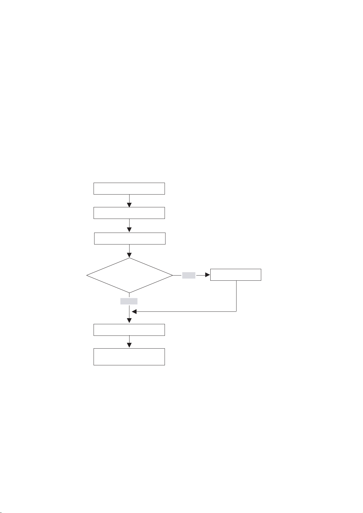
Installation procedure
Configuring
Do you want to
set up a subnet?
Mounting
Wiring
YES
2
Networking
NO
Addressing
Installation completed,
continue with commissioning
Basic rules for trouble-free operation of the S7 system
In view of the many and versatile applications, we can only provide basic rules for the
electrical and mechanical installation in this section.
You have to at least keep to these basic rules in order to obtain a fully functional SIMATICS7 system.
S7-300, CPU 31xC and CPU 31x: Installation
Operating Instructions, Edition 08/2004, A5E00105492-05
2-1
Page 20

Installation Order
Modifying the existing S7 system structure
To modify the configuration of an existing system, proceed as described earlier.
Reference
Note
When adding a new signal module, always refer to the relevant module information.
Also refer to the description of the various modules in the manual:
Automation Systems, Module Data Reference Manual
.
SIMATIC S7-300
S7-300, CPU 31xC and CPU 31x: Installation
2-2 Operating Instructions, Edition 08/2004, A5E00105492-05
Page 21
S7-300 components
3.1 Example of an S7-300 configuration
5
123
SF
BUSF
DC5V
FRCE
RUN
STOP
4
SF
BUSF
DC5V
FRCE
RUN
STOP
3
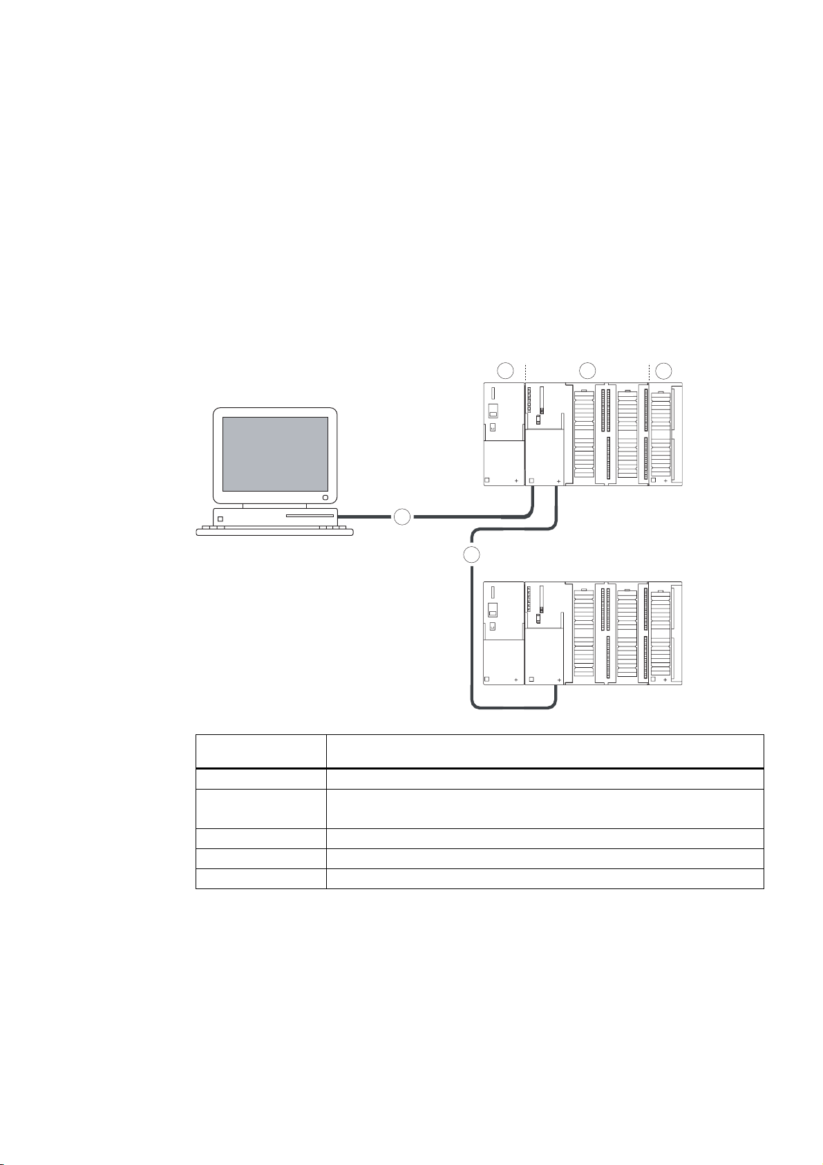
The figure illustrates
the following
(1) Power supply (PS) module
(2) Central processing unit (CPU)
(3) Signal module (SM)
(4) PROFIBUS bus cable
(5) Cable for connecting a programming device (PG)
You use a programming device (PG) to program the S7300 PLC. Use the PG cable to
interconnect the PG with the CPU.
To commission or program a CPU with PROFINET interface, you may also use an Ethernet
cable to interconnect the PG with the PROFINET connector of the CPU. Please note that
you need to adjust the Ethernet interface on your PG.
Several S7-300 CPUs communicate with one another and with other SIMATIC S7 PLCs via
the PROFIBUS cable. Several S7-300 are connected via the PROFIBUS bus cable.
S7-300, CPU 31xC and CPU 31x: Installation
Operating Instructions, Edition 08/2004, A5E00105492-05
the following S7-300 components
The example in the figure shows a CPU 31xC with integrated I/O.
3-1
Page 22
S7-300 components
SIEMENS
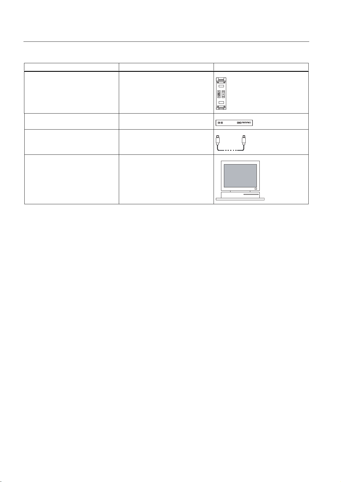
3.2 Overview of the vital modules of an S7-300
3.2 Overview of the vital modules of an S7-300
You can choose from a number of modules for installing and commissioning the S7-300. The
most important modules and their functions are shown below.
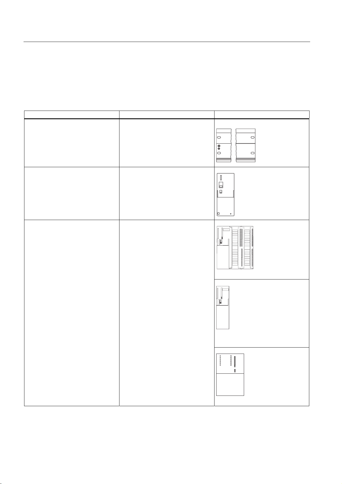
Table 3-1 S7-300 components:
Component Function Illustration
Mounting rail
Accessories:
• Shielding terminal
Power supply (PS) module The PS converts the line voltage
S7-300 racks
(120/230 VAC) into a 24 VDC operating
voltage, and supplies the S7-300 and
its 24 VDC load circuits.
CPU
Accessories:
• Front connectors (CPU 31xC only)
The CPU executes the user program,
supplies 5 V to the S7-300 backplane
bus, and communicates with other
nodes of an MPI network via the MPI
interface.
Additional features of specific CPUs:
• DP master or DP slave on a
PROFIBUS subnet
• Technological functions
• PtP communication
• Ethernet communication via
integrated PROFINET interface
SIEMENS
A CPU 31xC, for example
A CPU 312, 314, or 315-2 DP, for
example
A CPU 317, for example
S7-300, CPU 31xC and CPU 31x: Installation
3-2 Operating Instructions, Edition 08/2004, A5E00105492-05
Page 23
S7-300 components
3.2 Overview of the vital modules of an S7-300
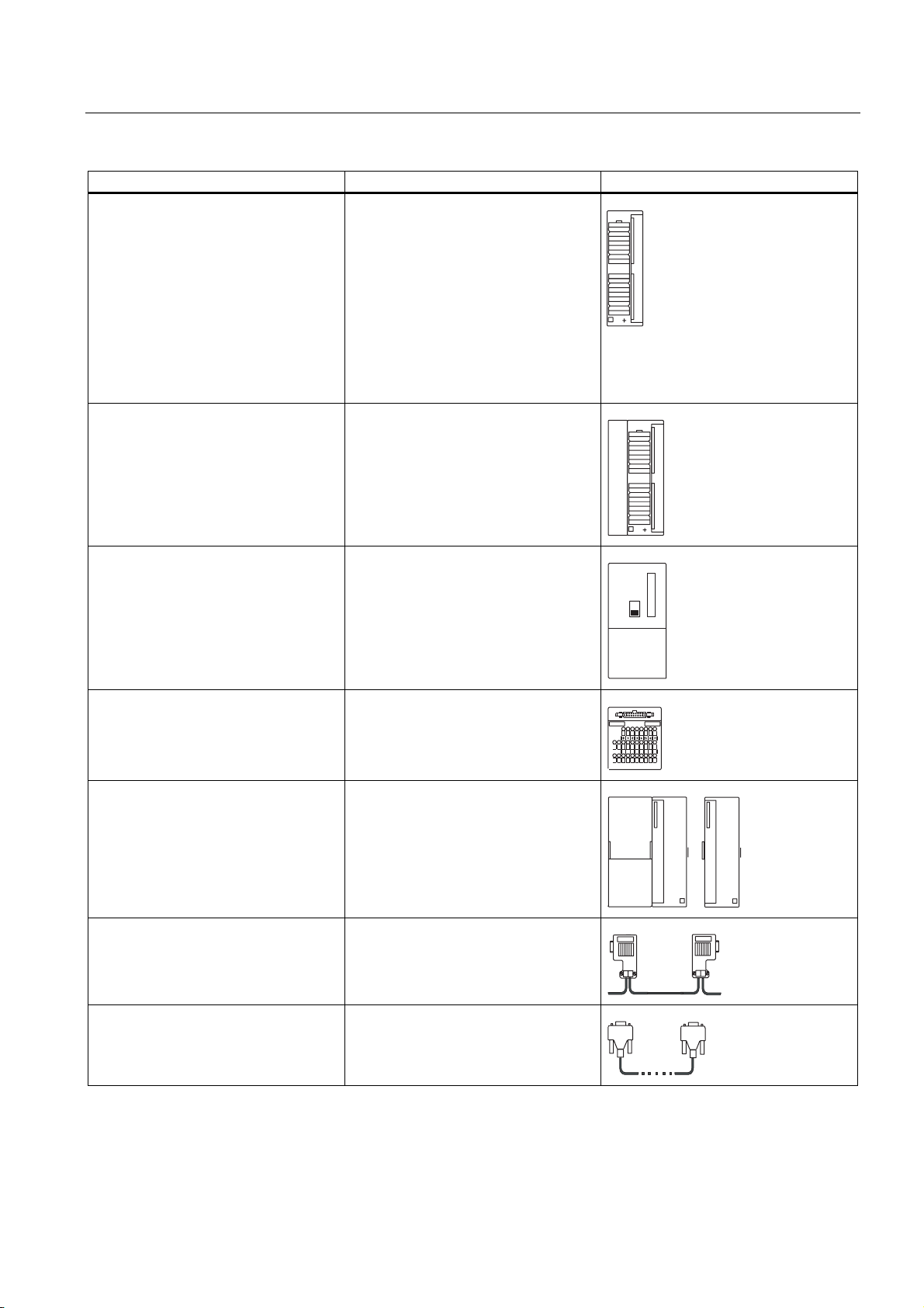
Component Function Illustration
Signal modules (SM)
• Digital input modules
• Digital output modules
• Digital I/O modules,
• Analog input modules
• Analog output modules
• Analog I/O modules
Accessories:
• Front connectors
Function modules (FM)
Accessories:
• Front connectors
The SM matches different process
signal levels to the S7-300.
The FM performs time-critical and
memory-intensive process signal
processing tasks.
Positioning or controlling, for example
Communication processor (CP)
Accessories: Connecting cable
SIMATIC TOP connect
Accessories:
• Front connector module with ribbon
cable terminals
Interface module (IM)
Accessories:
• Connecting cable
PROFIBUS cable with bus connector Interconnect the nodes of an MPI or
The CP relieves the CPU of
communication tasks.
Example: CP 342-5 DP for connecting
to PROFIBUS DP
Wiring of digital modules
The IM interconnects the various rows
in an S7-300
PROFIBUS subnet
PG cable Connects a PG/PC to a CPU
S7-300, CPU 31xC and CPU 31x: Installation
Operating Instructions, Edition 08/2004, A5E00105492-05
3-3
Page 24
S7-300 components
3.2 Overview of the vital modules of an S7-300
Component Function Illustration
RS 485 repeater The repeater is used to amplify the
signals and to couple segments of an
MPI or PROFIBUS subnet.
Switch A switch is used to interconnect the
Twisted-pair cables with RJ45
connectors.
Ethernet nodes.
Interconects devices with Ethernet
interface (a switch with a
CPU 317-2 PN/DP, for example)
Programming device (PG) or PC with
the STEP 7 software package
You need a PG to configure, set
parameters, program and test your
S7-300
S7-300, CPU 31xC and CPU 31x: Installation
3-4 Operating Instructions, Edition 08/2004, A5E00105492-05
Page 25

Configuring
4.1 Overview
There, you can find all the necessary information
• for the mechanical configuration of an S7-300,
• for the electrical configuration of an S7-300,
• that has to be observed in networking.
Reference
• For further information, refer to the
(6ES7398-8EA00-8AA0), or
• the
4.2 Basic engineering principles
SIMATIC NET Twisted-Pair and Fiber-Optic Networks
(6GK1970-1BA10-0AA0)
Communication with SIMATIC
Manual
4
manual
Important information for engineering
Warning
Open equipment
S7-300 modules are open equipment. That is, the S7-300 must be installed in a cubicle,
cabinet or electrical control room which can only be accessed using a key or tool. Only
trained or authorized personnel are allowed access to such cubicles, cabinets or electrical
operating rooms.
S7-300, CPU 31xC and CPU 31x: Installation
Operating Instructions, Edition 08/2004, A5E00105492-05
4-1
Page 26

Configuring
n
4.2 Basic engineering principles
Caution
Operation of an S7-300 in plants or systems is defined by special set of rules and
regulations, based on the relevant field of application. Observe the safety and accident
prevention regulations for specific applications, for example, the machine protection
directives. This chapter and the appendix
provide an overview of the most important rules you need to observe when integrating an
S7-300 into a plant or a system.
General rules and regulations on S7-300 operatio
Central unit (CU) and expansion module (EM)
An S7-300 PLC consists of a central unit (CU) and of one or multiple expansion modules.
The rack containing the CPU is the central unit (CU). Racks equipped with modules and
connected to the CU form the expansion modules (EMs) of the system.
Use of an expansion module (EM)
You can use EMs if the CU runs out of slots for your application.
When using EMs, you might require further power supply modules in addition to the extra
racks and interface modules (IM). When using interface modules you must ensure
compatibility of the partner stations.
Racks
The rack for your S7-300 is a mounting rail. You can use this rail to mount all modules of
your S7-300 system.
S7-300, CPU 31xC and CPU 31x: Installation
4-2 Operating Instructions, Edition 08/2004, A5E00105492-05
Page 27

Configuring
DC5V
FRCE
RUN
STOP
4.2 Basic engineering principles
Horizontal and vertical installation
You can mount an S7-300 either vertically or horizontally. The following ambient air
temperatures are permitted:
• Vertical assembly: 0 °C to 40 °C
• Horizontal assembly: 0 °C to 60 °C
Always install the CPU and power supply modules on the left or at the bottom.
1
1
SM
SM
SM
1
SM
2
SM
SM
SM
SM
SM
SM
SM
1
3
SM
SM
SM
SM
SM
PS
DC5V
FRCE
RUN
STOP
CPU
CPU
DC5
FRCE
RUN
STOP
PS
3
The figure illustrates the following
(1) the vertical installation of an S7-300
(2) the horizontal installation of an S7-300
(3) the mounting rail
S7-300, CPU 31xC and CPU 31x: Installation
Operating Instructions, Edition 08/2004, A5E00105492-05
4-3
Page 28

Configuring
4.3 Component dimensions
4.3 Component dimensions
Length of the mounting rails
Table 4-1 Mounting rails - Overview
Mounting rail length Usable length for modules Order number
160 mm 120 mm 6ES7 390-1AB60-0AA0
482.6 mm 450 mm 6ES7 390-1AE80-0AA0
530 mm 480 mm 6ES7 390-1AF30-0AA0
830 mm 780 mm 6ES7 390-1AJ30-0AA0
2000 mm cut to length as required 6ES7 390-1BC00-0AA0
In contrast to other rails, the 2 m mounting rail is not equipped with any fixing holes. These
must be drilled, allowing optimal adaptation of the 2 m rail to your application.
Dimensions of modules
Table 4-2 Module width
Module Width
Power supply module PS 307, 2 A 50 mm
Power supply module PS 307, 5 A 80 mm
Power supply module PS 307, 10 A 200 mm
CPU For information on assembly dimensions,
refer to the Technical Data in
CPU 31x Manual, Technical Data
Analog I/O modules 40 mm
Digital I/O modules 40 mm
Simulator module SM 374 40 mm
Interface modules IM 360 and IM 365 40 mm
Interface module IM 361 80 mm
CPU 31xC and
.
• Module height: 125 mm
• Module height with shielding contact element: 185 mm
• Maximum assembly depth: 130 mm
• Maximum assembly depth of a CPU with an inserted DP connector with angled cable
feed: 140 mm
• Maximum assembly depth with open front panel (CPU): 180 mm
Dimensions of other modules such as CPs, FMs etc. are found in the relevant manuals.
S7-300, CPU 31xC and CPU 31x: Installation
4-4 Operating Instructions, Edition 08/2004, A5E00105492-05
Page 29
Configuring
4.3 Component dimensions
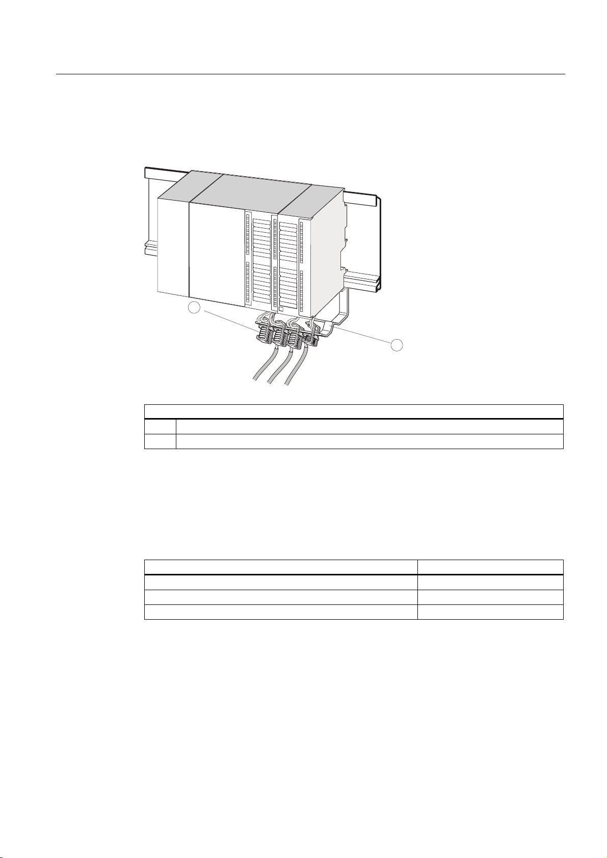
Shielding contact element
The direct contact between the shielding contact element and the mounting rail makes it
easy for you to connect all shielded cables of your S7 modules to ground.
PS
CPU
1
2
The figure illustrates the following
(1) Shielding terminals
(2) The bracket.
Mount the bracket (order no. 6ES5 390-5AA0-0AA0) to the rail using the two screw bolts. If
you use a shielding contact element, the specified dimensions are measured from the base
of the element.
• Width of the shielding contact element: 80 mm
• Mountable shielding terminals per shielding contact element max. 4
Table 4-3 Shielding terminals - Overview
Cable with shielding diameter Shielding terminal order no.
Cable with 2 mm to 6 mm shielding diameter 6ES7 390–5AB00–0AA0
Cable with 3 mm to 8 mm shielding diameter 6ES7 390–5BA00–0AA0
Cable with 4 mm to 13 mm shielding diameter 6ES7 390–5CA00–0AA0
S7-300, CPU 31xC and CPU 31x: Installation
Operating Instructions, Edition 08/2004, A5E00105492-05
4-5
Page 30
Configuring
4.4 Required clearances
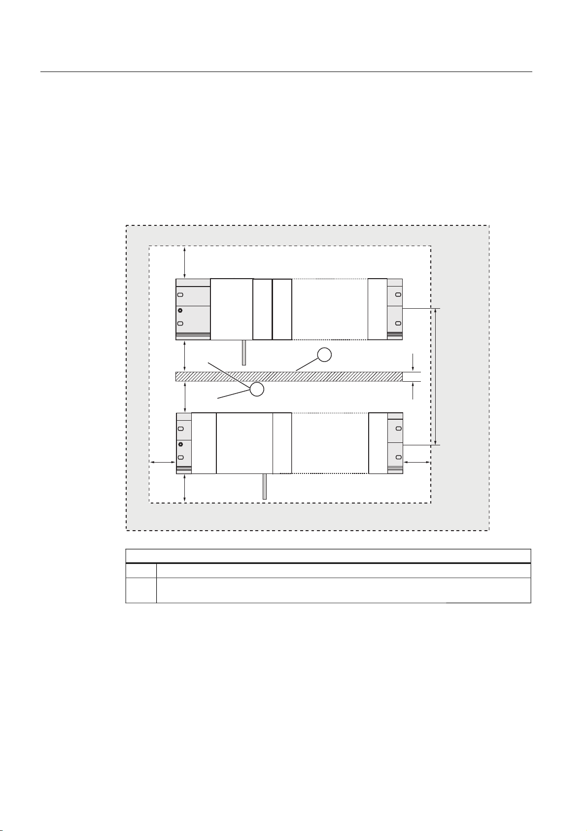
4.4 Required clearances
You must maintain the clearance shown in the figure in order to provide sufficient space for
installing the modules, and to allow the dissipation of heat generated by the modules.
The S7-300 assembly on multiple racks shown in the figure below shows the clearance
between racks and adjacent components, cable ducts, cabinet walls etc.
For example, when routing your module wiring through cable duct, the minimum clearance
between the bottom of the shielding contact element and the cable duct is 40 mm.
PP
PP
PP
PP
36
PP
&38
&38
60
60
60
60
PPD
D
60
PP
The figure illustrates the following
(1) Wiring with cable duct
(2) Minimum clearance between the cable duct and the bottom edge of the shielding contact
element is 40 mm
S7-300, CPU 31xC and CPU 31x: Installation
4-6 Operating Instructions, Edition 08/2004, A5E00105492-05
Page 31

Configuring
4.5 Arrangement of modules on a single rack
4.5 Arrangement of modules on a single rack
Reasons for using one or multiple racks
The number of racks you need will depend on your application.
Reasons for using a single rack: Reasons for distributing modules between
several racks
• Compact, space-saving use of all your
modules
• Local use of all modules
• Fewer signals to be processed
• More signals to be processed
• Insufficient number of slots
Note
If you opt for the installation on a single rack, insert a dummy module to the right of the CPU
(order no.: 6ES7 370-0AA01-0AA0). This gives you the option of adding a second rack for
your application, simply by replacing the dummy module with an interface module, and
without having to reinstall and rewire the first rack.
Rules: Layout of modules on a single module rack
The following rules apply to module installations on a single rack:
• No more than eight modules (SM, FM, CP) may be installed to the right of the CPU.
• The accumulated power consumption of modules mounted on a rack may not exceed
1.2 A on the S7-300 backplane bus.
Reference
For further information, refer to the technical data, for example, in the
Specifications Reference Manual
Example
The figure below shows a layout with eight signal modules in an S7-300 assembly.
or in the
Reference Manual
S7-300 Module
for your CPU.
PS
S7-300, CPU 31xC and CPU 31x: Installation
Operating Instructions, Edition 08/2004, A5E00105492-05
CPU
SM1
SM2
SM3
SM4
SM5
SM6
SM7
SM8
4-7
Page 32

Configuring
4.6 Distribution of modules to several racks
4.6 Distribution of modules to several racks
Exceptions
With CPU 312 and CPU 312C, only a single-row configuration on a rack is possible.
Using interface modules
If you are planning an assembly in multiple racks, then you will need interface modules (IM).
Interface modules route the backplane bus of an S7-300 to the next rack.
The CPU is always located on rack 0.
Table 4-4 Interface modules - Overview
Properties Two or more rows Cost-effective 2-row configuration
Send IM in rack 0 IM 360
order no..: 6ES7 360-3AA01-0AA0
Receiver IM in racks 1 to 3 IM 361
order no..: 6ES7 361-3CA01-0AA0
Maximum number of expansion
modules
Length of connecting cables 1 m (6ES7 368-3BB01-0AA0)
Remarks - Rack 1 can only receive signal modules;
3 1
2.5 m (6ES7 368-3BC51-0AA0)
5 m (6ES7 368-3BF01-0AA0)
10 m (6ES7 368-3CB01-0AA0)
IM 365
order no..: 6ES7 365-0AB00-0AA0
IM 365 (hard-wired to send IM 365)
1 m (hard-wired)
the accumulated current load is limited to
1.2 A, whereby the maximum for rack 1 is
0.8 A
These restrictions do not apply to operation
with interface modules IM 360/IM 361
S7-300, CPU 31xC and CPU 31x: Installation
4-8 Operating Instructions, Edition 08/2004, A5E00105492-05
Page 33

Configuring
4.6 Distribution of modules to several racks
Rules: arrangement of the modules on several racks
Please note the following points if you wish to arrange your modules on multiple racks:
• The IM always uses slot 3 (slot 1: power supply module; slot 2: CPU, slot 3: Interface
module)
• It is always on the left before the first signal module.
• No more than 8 modules (SM, FM, CP) are permitted per rack.
• The number of modules (SM, FM, CP) is limited by the permitted current consumption on
the S7-300 backplane bus. The accumulated power consumption may not exceed 1.2 A
per row.
Note
For information on the power consumption of the various modules, refer to the
Specifications Reference Manual.
Module
Rules: Interference-proof interfacing
Special shielding and grounding measures are not required if you interconnect the CU and
EM using suitable interface modules (Send IM and Receive IM).
However, you must ensure
• a low impedance interconnection of all racks,
• that the racks of a grounded assembly are grounded in a star pattern,
• that the contact springs on the racks are clean and not bent, thus ensuring that
interference currents are properly discharged to ground.
S7-300, CPU 31xC and CPU 31x: Installation
Operating Instructions, Edition 08/2004, A5E00105492-05
4-9
Page 34
Configuring
4.6 Distribution of modules to several racks
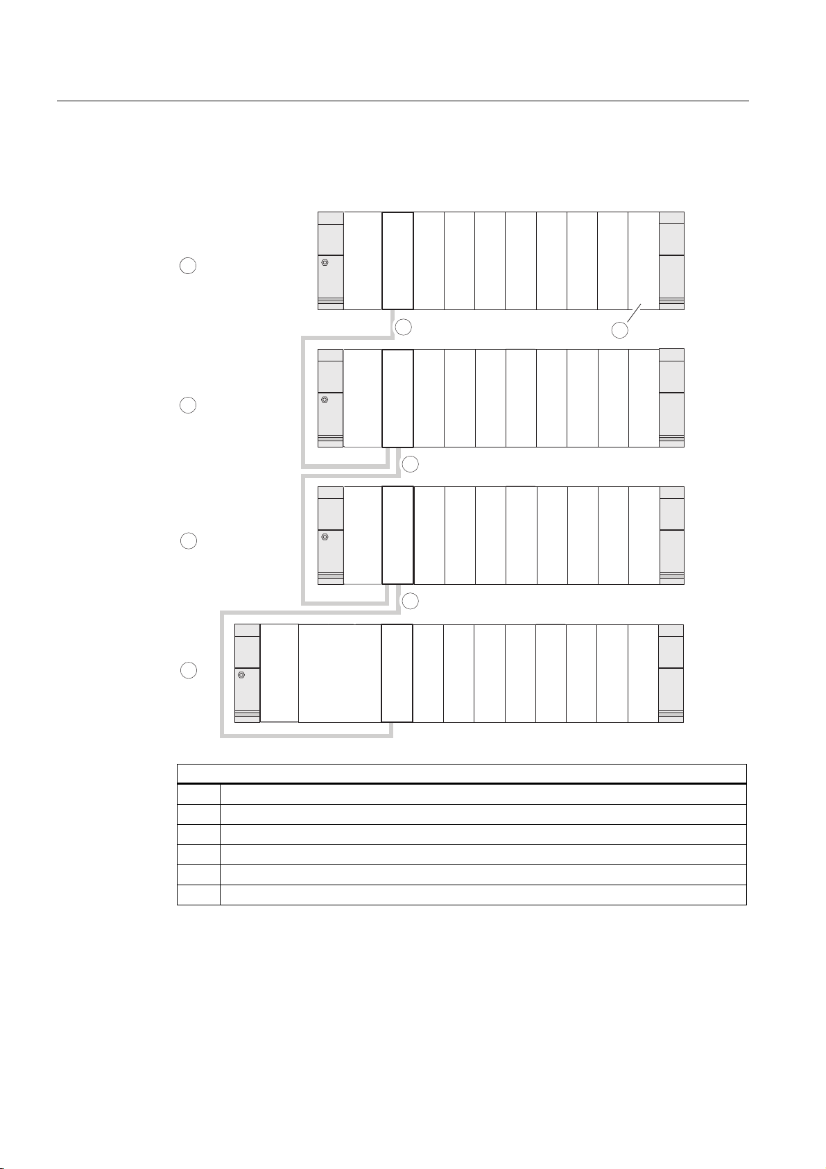
Example: Full assembly using four racks
The figure shows the arrangement of modules in an S7-300 assembly on 4 racks.
SM4
SM4
SM4
SM5
SM5
SM5
SM6
SM6
SM6
SM7
6
SM7
SM7
SM8
SM8
SM8
SM3
SM2
SM1
PS
PS
IM
IM
IM
IM
5
SM3
SM2
SM1
5
SM3
SM2
SM1
5
4
4
3
2
1
PS
CPU
IM
IM
SM1
SM2
SM3
SM4
SM5
SM6
SM7
SM8
The figure illustrates the following
(1) Rack 0 (central unit)
(2) Rack 1 (expansion module)
(3) Rack 2 (expansion module)
(4) Rack 3 (expansion module)
(5) The connecting cable 368
(6) Restriction for CPU 31xC. When this CPU is used, do not insert SM 8 into Rack 4.
S7-300, CPU 31xC and CPU 31x: Installation
4-10 Operating Instructions, Edition 08/2004, A5E00105492-05
Page 35

Configuring
4.7 Selection and installation of cabinets
4.7 Selection and installation of cabinets
Reasons for installing an S7-300 in a cabinet
Your S7-300 should be installed in a cabinet,
• if you plan a larger system,
• if you are using your S7-300 systems in an environment subject to interference or
contamination, and
• to meet UL/CSA requirements for cabinet installation.
Selecting and dimensioning cabinets
Take the following criteria into account:
• ambient conditions at the cabinet's place of installation
• the specified mounting clearance for racks (mounting rails)
• accumulated power loss of all components in the cabinet.
The ambient conditions (temperature, humidity, dust, chemical influence, explosion hazard)
at the cabinet's place of installation determine the degree of protection (IP xx) required for
the cabinet.
Reference for degrees of protection
For further information on the degrees of protection, refer to IEC 529 and DIN 40050.
The power dissipation capability of cabinets
The power dissipation capability of a cabinet depends on its type, ambient temperature and
on the internal arrangement of devices.
Reference for power loss
For detailed information on power dissipation, refer to the Siemens catalogs NV21 and ET1.
Specification of cabinet dimensions
Note the following specifications when you determine the dimensions of a cabinet for your
S7-300 installation:
• Space required for racks (mounting rails)
• Minimum clearance between the racks and cabinet walls
• Minimum clearance between the racks
• Space required for cable ducts or fan assemblies
• Position of the stays
S7-300, CPU 31xC and CPU 31x: Installation
Operating Instructions, Edition 08/2004, A5E00105492-05
4-11
Page 36

Configuring
4.7 Selection and installation of cabinets
Warning
Modules may get damaged if exposed to excess ambient temperatures.
Reference for ambient temperatures
For information on permitted ambient temperatures, refer to the
Module data
Reference Manual.
S7-300 Automation System,
S7-300, CPU 31xC and CPU 31x: Installation
4-12 Operating Instructions, Edition 08/2004, A5E00105492-05
Page 37

Configuring
4.7 Selection and installation of cabinets
Overview of typical cabinet types
The table below gives you an overview of commonly used cabinet types. It shows you the
applied principle of heat dissipation, the calculated maximum power loss and the degree of
protection.
Table 4-5 Cabinet types
Open cabinets Closed cabinets
Enclosed ventilation by
means of natural
convection
Increased enclosed
ventilation
Natural convection Forced convection with
rack fan, improvement
of natural convection
Forced convection with
heat exchanger,
internal and external
auxiliary ventilation
Mainly inherent heat
dissipation, with a
small portion across
the cabinet wall.
Degree of protection
IP 20
Typical power dissipation under following marginal conditions:
• Cabinet size: 600 mm x 600 mm x 2,200 mm
• Difference between the outer and inner temperature of the cabinet is 20 °C (for other temperature differences refer to
the temperature charts of the cabinet manufacturer)
up to 700 W up to 2,700 W (with
Higher heat dissipation
with increased air
movement.
Degree of protection
IP 20
fine filter up to
1,400 W)
Heat dissipation only
across the cabinet
wall; only low power
losses permitted. In
most cases, the heat
accumulates at the top
of the cabinet interior.
Degree of protection
IP 54
up to 260 W up to 360 W up to 1,700 W
Heat dissipation only
across the cabinet
wall. Forced
convection of the
interior air improves
heat dissipation and
prevents heat
accumulation.
Degree of protection
IP 54
Heat dissipation by
heat exchange
between heated
internal air and cool
external air. The
increased surface of
the pleated profile of
the heat exchanger
wall and forced
convection of internal
and external air
provide good heat
dissipation.
Degree of protection
IP 54
S7-300, CPU 31xC and CPU 31x: Installation
Operating Instructions, Edition 08/2004, A5E00105492-05
4-13
Page 38

Configuring
4.8 Example: Selecting a cabinet
4.8 Example: Selecting a cabinet
Introduction
The sample below clearly shows the maximum permitted ambient temperature at a specific
power loss for different cabinet designs.
Installation
The following device configuration should be installed in a cabinet:
• Central unit, 150 W
• Expansion modules, each with 150 W
• Load power supply under full load, 200 W
This results in an accumulated power loss of 650 W.
Power loss dissipated
The diagram in the figure below shows guide values for the permitted ambient temperature
of a cabinet with the dimensions 600 mm x 600 mm x 2,000 mm, based on the accumulated
power loss. These values only apply if you maintain the specified assembly and clearance
dimensions for racks (rails).
Ambient temperature in °C
60
50
1
40
2
30
1
3
20
200
400 600 800 1000 1200
Power loss in W
1400
Trend shows you the following cabinet type
(1) Closed cabinet with heat exchanger (heat exchanger size 11/6
(920 mm x 460 mm x 111 mm)
(2) Cabinet with through-ventilation by natural convection
(3) Closed cabinet with natural convection and forced convection by equipment fans
S7-300, CPU 31xC and CPU 31x: Installation
4-14 Operating Instructions, Edition 08/2004, A5E00105492-05
Page 39

Configuring
4.9 Electrical assembly, protective measures and grounding
Result
The figure below shows the resultant ambient temperatures, based on an accumulated
power loss of 650 W:
Table 4-6 Cabinet selection
Cabinet design Maximum permitted ambient
temperature
Closed with natural convection and forced convection (trend
3)
Open with through-ventilation (trend 2) approx. 38 °C
Closed with heat exchanger (trend 1) approx. 45 °C
Cabinet types suitable for horizontal installation of the S7-300:
• open, with closed ventilation
• closed, with heat exchanger
Operation not possible
4.9 Electrical assembly, protective measures and grounding
4.9.1 Grounding concept and overall structure
This section contains information about the overall configuration of an S7-300 connected to a
grounded TN-S network:
• Circuit-breaking devices, short-circuit and overload protection to VDE 0100 and VDE
0113
• Load power supplies and load circuits
• Grounding concept
Definition: Grounded mains
Note
An S7-300 can be used in many different ways, so we can only describe the basic rules
for the electrical installation in this document. Those basic rules are a must in order to
achieve a fully functional S7-300 system.
In a grounded mains network, the neutral conductor is always bonded to ground. A shortcircuit to ground of a live conductor, or of a grounded part of the system, trips the protective
devices.
S7-300, CPU 31xC and CPU 31x: Installation
Operating Instructions, Edition 08/2004, A5E00105492-05
4-15
Page 40

Configuring
4.9 Electrical assembly, protective measures and grounding
Specified components and protective measures
A number of components and protective measures are prescribed for plant installations. The
type of components and the degree of compulsion pertaining to the protective measures will
depend on the VDE specification applicable to your particular plant.
The table below shows components and protective measures.
Table 4-7 VDE specifications for the installation of a PLC system
Compare ... 1) VDE 0100 VDE 0113
Disconnect devices for control
systems, signal generators and
final control elements
Short-circuit / overload
protection:
In groups for signal generators
and final control elements
Load power supply for AC load
circuits with more than five
electromagnetic devices
(1) ...Part 460:
Master switch
(2) ...Part 725:
Single-pole fusing of
circuits
(3) Galvanic isolation by
transformer
recommended
... Part 1:
Load disconnect switch
... Part 1:
• With grounded secondary
power circuit: single-pole
fusing
• Otherwise: fusing of all poles
Electrical isolation by transformer
mandatory
1) This column refers to the indexes of the figure in the chapter Overview: Grounding.
Reference
For further information on protective measures, refer to the Appendix.
4.9.2 Installing an S7-300 with grounded reference potential
Introduction
During installation of an S7-300 with grounded reference potential interference current is
discharged to the ground conductor / to earth. A grounding slide contact is used for this
except with CPU 31xC.
Note
Your CPU is supplied with grounded reference potential. Therefore, if you wish to install an
S7-300 with grounded reference potential, you do not need to modify your CPU!
S7-300, CPU 31xC and CPU 31x: Installation
4-16 Operating Instructions, Edition 08/2004, A5E00105492-05
Page 41

Configuring
4.9 Electrical assembly, protective measures and grounding
Grounded reference potential of the CPU 31x
The figure shows an S7-300 configuration with grounded reference potential (factory state.)
1
L+
M
M
M
10M
2
<100 nF
3
The figure illustrates the following
(1) Grounding slide contact in grounded state
(2) Ground of the internal CPU circuitry
(3) The mounting rail
Note
Do not pull out the grounding slide contact when you install an S7-300 with grounded
reference potential.
4.9.3 Configuring an S7-300 with ungrounded reference potential (not CPU 31xC)
Introduction
During installation of an S7-300 with ungrounded reference potential interference currents
are discharged to the ground conductor / to ground via an RC combination integrated in the
CPU.
Note
An S7-300 with a CPU 31xC cannot be configured ungrounded.
S7-300, CPU 31xC and CPU 31x: Installation
Operating Instructions, Edition 08/2004, A5E00105492-05
4-17
Page 42

Configuring
4.9 Electrical assembly, protective measures and grounding
Application
In large systems, the S7-300 may require a configuration with grounded reference potential
due to ground-fault monitoring. This is the case, for example, in chemical industry and power
stations.
Ungrounded reference potential of the CPU 31x
The figure shows an S7-300 configuration with floating potential
L+
M
M
1
M
10M
2
<100 nF
3
The figure illustrates the following
(1) How to implement an ungrounded reference potential in your CPU: Use a screwdriver with
3.5 mm blade width to push the grounding slide contact forwards in the direction of the arrow
until it snaps into place.
(2) Ground of the internal CPU circuitry
(3) The mounting rail.
Note
You should set up the ungrounded reference potential before you mount the device on the
rail. If you have already installed and wired up the CPU, you may have to disconnect the MPI
interface before you pull out the grounding slide contact.
S7-300, CPU 31xC and CPU 31x: Installation
4-18 Operating Instructions, Edition 08/2004, A5E00105492-05
Page 43

Configuring
4.9 Electrical assembly, protective measures and grounding
4.9.4 Modules with isolated or common potential?
Isolated modules
Isolated modules are installed with galvanic isolation between the reference potentials of the
control circuit (M
Field of application
Use isolated modules for:
• All AC load circuits
• DC load circuits with separate reference potential
Examples:
– DC load circuits containing sensors which are connected to different reference
potentials (for example, if grounded sensors are located at a considerable distance
from the control system and equipotential bonding is not possible)
– DC load circuits with grounded positive pole (L+) (battery circuits.)
) and load circuit (M
internal
external
.)
Isolated modules and grounding concept
You can always use isolated modules, irrespective of the grounding state of the control
system's reference potential.
S7-300, CPU 31xC and CPU 31x: Installation
Operating Instructions, Edition 08/2004, A5E00105492-05
4-19
Page 44

Configuring
4.9 Electrical assembly, protective measures and grounding
Example: Assembly with CPU 31xC and isolated modules
The figure below shows an example of such a configuration: A CPU 31xC with isolated
modules. The CPU 31xC (1) is automatically grounded.
L1
N
PE
Common grounding
line in the cabinet
L+
M
external
24 V DC load power supply
Common potential modules
In a configuration containing modules with common potential, the reference potentials of the
control circuit (M
L1
N
PS
S7-300 CPU
1
L+
M
) and analog circuit (M
internal
µP
DI
) are not galvanically isolated.
analog
DO
230 V AC
load power supply
U
internal
Data
M
internal
L1
N
S7-300, CPU 31xC and CPU 31x: Installation
4-20 Operating Instructions, Edition 08/2004, A5E00105492-05
Page 45
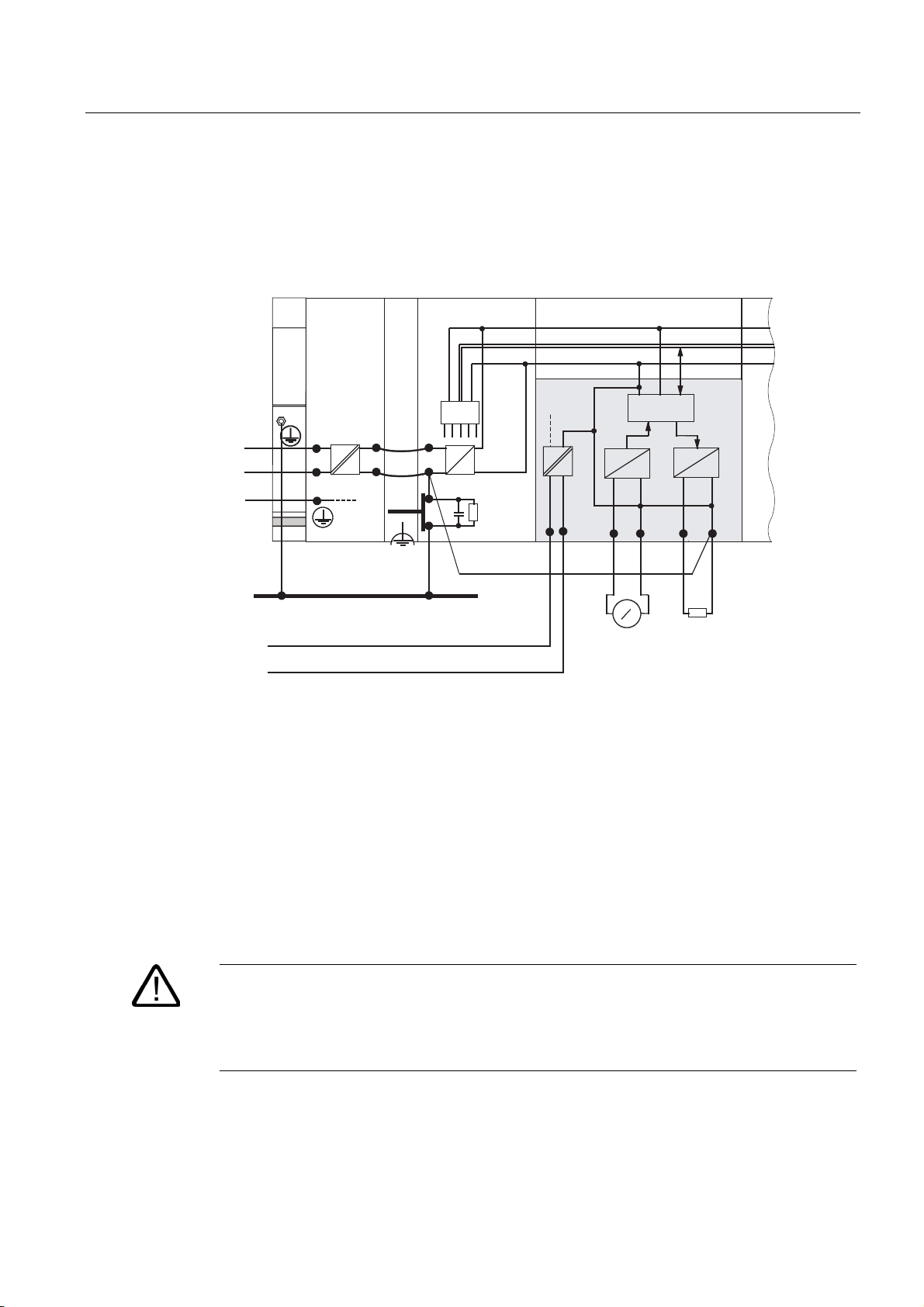
Configuring
l
l
4.9 Electrical assembly, protective measures and grounding
Example: Installing an S7-300 with common potential modules
When using an SM 334 AI 4/AO 2 analog I/O module, connect one of the grounding
terminals M
The figure below shows an example of such a configuration: An S7-300 with common
potential modules
to the CPU's chassis ground.
analog
PS
L1
N
PE
L+
M
external
24 V DC load power supply
L1
N
Common grounding
line in the cabinet
L+
M
M
S7-300 CPU
µ
P
1 mm
4AI/2AO
U
interna
Data
M
interna
D
2
++
V
A
D
A
M
analog
A
4.9.5 Grounding measures
Bonding to ground
Low-impedance connections to ground reduce the risk of electric shock as a result of a
short-circuit or system fault. Low-impedance connections (large surface, large-surface
contact) reduce the effects of interference on the system or the emission of interference
signals. An effective shielding of cables and devices is also a significant contribution.
Warning
All protection class 1 devices, and all larger metal parts, must be bonded to protective
ground. That is the only way to safely protect operators from electrical shock. This also
discharges any interference transmitted from external power supply cables, signal cables or
cables to the I/O devices.
S7-300, CPU 31xC and CPU 31x: Installation
Operating Instructions, Edition 08/2004, A5E00105492-05
4-21
Page 46

Configuring
4.9 Electrical assembly, protective measures and grounding
Measures for protective grounding
The table below shows an overview of the most important measures for protective
grounding.
Table 4-8 Measures for protective grounding
Device Measures
Cabinet / mounting frame Connection to central ground (equipotential busbar, for example)
using cables with protective conductor quality
Rack / mounting rail Connection to central ground, using cables with a minimum cross-
section of 10 mm
interconnected with larger metallic parts.
Module None
I/O Device Grounding via grounding-type plug
Sensors and final control
elements
Grounding in accordance with regulations applying to the system
2
, if the rails are not installed in the cabinet and not
Rule: Connect the cable shielding to ground
You should always connect both ends of the cable shielding to ground / system ground. This
is the only way to achieve an effective interference suppression in the higher frequency
range.
Attenuation is restricted to the lower frequency range if you connect only one end of the
shielding (that is, at the start or end of the cable) to ground. One-sided shielding connections
could be more favorable in situations
• not allowing the installation of an equipotential bonding conductor,
• where analog signals (some mA or A) are transferred,
• or if foil shielding is used (static shielding).
Note
Potential differences between two grounding points might cause an equipotential current
flow across shielding connected at both ends. In this case, you should install an
additional equipotential bonding conductor.
Caution
Always avoid the flow of operating current to ground.
S7-300, CPU 31xC and CPU 31x: Installation
4-22 Operating Instructions, Edition 08/2004, A5E00105492-05
Page 47

Configuring
4.9 Electrical assembly, protective measures and grounding
Rule: Load circuit grounding
You should always ground the load circuits. This common reference potential (ground)
ensures proper functioning.
Note
(not valid for CPU 31xC):
If you want to locate a fault to ground, provide your load power supply (terminal L or M) or
the isolating transformer with a removable connection to the protective conductor (see
Overview: Grounding
section 4).
Connecting the load voltage reference potential
A complex system containing many output modules requires an additional load voltage for
switching the final control elements.
The table below shows how to connect the load voltage reference potential M
various configurations.
Table 4-9 Connecting the load voltage reference potential
Installation common potential modules isolated modules Note
grounded Connect M
the CPU
ungrounded Connect M
the CPU
external
external
with M on
with M on
Connect or do not connect
M
to the grounding
external
busbar
Connect or do not connect
M
to the grounding
external
busbar
for the
external
-
Ungrounded installation
with CPU 31xC is not
possible
S7-300, CPU 31xC and CPU 31x: Installation
Operating Instructions, Edition 08/2004, A5E00105492-05
4-23
Page 48

Configuring
4.9 Electrical assembly, protective measures and grounding
4.9.6 Overview: Grounding
CPU 31xC
The figure below shows you the complete assembly of an S7-300 with CPU 31xC with a
power supply from TN-S mains. Apart from powering the CPU, the PS 307 also supplies the
load current for the 24 VDC modules. Note: The layout of the power connections does not
correspond with their physical arrangement; it was merely selected to give you a clear
overview.
L1
L2
L3
N
PE
Low-voltage distribution
e.g. TN-S system (3 x 400 V)
Cabinet
1
Profile rail
3
AC
AC
AC
DC
L1
N
PS
4
1
L+
M
Common grounding line in the cabinet
Load circuit
24 to 230 V AC for AC modules
Load circuit
5 to 60 V DC non-isolated DC modules
4
CPU
µP
2
2
SM
Signal modules
AC
DC
Table 4-10 Connecting the load voltage reference potential
The figure illustrates the following
The main switch
(1)
The short-circuit / overload protection
(2)
The load current supply (galvanic isolation)
(3)
This connection is made automatically for the CPU 31xC
(4)
S7-300, CPU 31xC and CPU 31x: Installation
2
Load circuit
5 to 60 V DC for isolated DC modules
4-24 Operating Instructions, Edition 08/2004, A5E00105492-05
Page 49

Configuring
4.9 Electrical assembly, protective measures and grounding
All CPUs except CPU 31xC
The figure below shows you the complete assembly of an S7-300 with TN-S mains supply
(does not apply to CPU 31xC). Apart from powering the CPU, the PS 307 also supplies the
load current for the 24 VDC modules.
Note: The layout of the power connections does not correspond with their physical
arrangement; it was merely selected to give you a clear overview.
L1
L2
L3
N
PE
Low-voltage distribution
e.g. TN-S system (3 x 400 V)
Cabinet
1
Profile rail
3
AC
AC
AC
DC
L1
PS
L+
M
N
M
5
Common grounding line in the cabinet
Load circuit
24 to 230 V AC for AC modules
Load circuit
4
5 to 60 V DC for non-isolated DC modules
CPU
µP
2
2
SM
Signal modules
AC
DC
Table 4-11 Connecting the load voltage reference potential
The figure illustrates the following
(1) The main switch
(2) The short-circuit / overload protection
(3) The load current supply (galvanic isolation)
(4) The removable connection to the grounding conductor, for ground fault localization
(5) The grounding slide contact of the CPU (not CPU 31xC)
S7-300, CPU 31xC and CPU 31x: Installation
Operating Instructions, Edition 08/2004, A5E00105492-05
2
Load circuit
5 to 60 V DC for isolated DC modules
4-25
Page 50

Configuring
4.10 Selecting the load power supply
4.10 Selecting the load power supply
Task of the load power supply
The load power supply feeds the input and output circuits (load circuits), and the sensors
and actuators.
Features of load power supply units
You will have to adapt the load power supply unit to your specific application. The table
below shows a comparison of the various load power supply units and their features to help
you make your choice:
Table 4-12 Features of load power supply units
Necessary for ... Feature of the load power
Modules requiring voltage
supplies ≤ 60 VDC or ≤ 25 VAC.
24 VDC load circuits
24 VDC load circuits
48 VDC load circuits
60 VDC load circuits
Load power supply requirements
Only an extra-low voltage of ≤ 60 VDC which is safely isolated from mains may be used as
load voltage. Safe isolation from mains can be achieved, for example, in accordance with
VDE 0100 Part 410 / HD 384-4-41 / IEC 364-4-41 (as functional extra-low voltage with safe
isolation) or VDE 0805 / EN 60950 / IEC 950 (as safety extra-low voltage SELV) or VDE
0106 Part 101.
Load current determination
The required load current is determined by the accumulated load current of all sensors and
actuators connected to the outputs.
Remarks
supply
Safety isolation This is a common feature of the
Siemens power supply series
PS 307 and SITOP power
series 6EP1.
Output voltage tolerances:
20.4 V to 28.8 V
40.8 V to 57.6 V
51 V to 72 V
-
A short-circuit induces a surge current at the DC outputs which is 2 to 3 times higher than
the rated output current, until the clocked electronic short-circuit protection comes into effect.
Make allowances for this increased short-circuit current when selecting your load power
supply unit. Uncontrolled load power supplies usually provide this excess current. With
controlled load power supplies, and particularly for low output power up to 20 A, always
ensure that the supply can handle this excess current.
S7-300, CPU 31xC and CPU 31x: Installation
4-26 Operating Instructions, Edition 08/2004, A5E00105492-05
Page 51

Configuring
4.10 Selecting the load power supply
Example: S7-300 with load power supply from PS 307
The figure below shows the overall S7-300 configuration (load power supply unit and
grounding concept), with TN-S mains supply. The PS 307 supplies the CPU and the load
current circuit of the 24 VDC modules.
Note
The layout of the power connections does not correspond with their physical arrangement; it
was merely selected to give you a clear overview.
/
/
/
1
3(
5DLO
/RZYROWDJHGLVWULEXWLRQ
HJ716V\VWHP[9
&DELQHW
36
/
1
6 &38
w3
/
0
0
60
Example: S7-300 with load power supply from PS 307
S7-300, CPU 31xC and CPU 31x: Installation
Operating Instructions, Edition 08/2004, A5E00105492-05
6LJQDOPRGXOHV
(TXLSRWHQWLDOEXVOLQH
LQWKHFDELQHW
2QORDGSRZHUFLUFXLWV
'&9IRU'&PRGXOHV
4-27
Page 52

Configuring
4.11 Planning subnets
4.11 Planning subnets
4.11.1 Overview
Subnets
Subnets available in SIMATIC for the various automation levels (process, cell, field and
actuator/sensor level ):
• Multi-Point Interface (MPI)
• PROFIBUS
• PROFINET (Industrial Ethernet)
• Point-to-point communication (PtP)
• Actuator/Sensor Interface (ASI)
Multi Point Interface (MPI)
Availability: For all CPUs described in this document.
MPI is a small area subnet containing a small number of nodes at the field/cell level. It is a
multipoint-capable interface in SIMATIC S7/M7 and C7, designed as PG interface, for
networking a small number of CPUs, or for low volume data exchange with PGs.
MPI always retains the last configuration of the transmission rate, node number and highest
MPI address, even after CPU memory reset, power failure or deletion of the CPU parameter
configuration.
It is advisable to use the PROFIBUS DP network components for your MPI network
configuration. The same configuration rules apply in this case. Exception: OWG modules are
not allowed in the MPI network.
PROFIBUS
Availability: CPUs with the "DP" name suffix are equipped with a PROFIBUS interface (CPU
315-2 DP, for example).
PROFIBUS represents the network at the cell and field level in the SIMATIC open,
multivendor communication system.
PROFIBUS is available in two versions:
1. PROFIBUS DP field bus for high-speed cyclic data exchange, and PROFIBUS-PA for
intrinsically safe applications (requires DP/PA coupler).
2. The cell level as PROFIBUS (FDL or PROFIBUS FMS) for high-speed data exchange
with communication partners at the same authorization level (can only be implemented
via CP).
S7-300, CPU 31xC and CPU 31x: Installation
4-28 Operating Instructions, Edition 08/2004, A5E00105492-05
Page 53

Configuring
4.11 Planning subnets
PROFINET (Industrial Ethernet)
Availability: CPUs with a "PN" name suffix are equipped a second interface, namely the
PROFINET interface (CPU 317-2 PN/DP, for example) A PROFINET interface, or
communication processors, can be used to implement Industrial Ethernet in an S7-300 CPU
system.
Industrial Ethernet, in an open multivendor communication system, represents the SIMATIC
network at the process and cell level. PROFINET CPUs, however, also support real-time
communication at the field level. This structure also supports S7 communication. Industrial
Ethernet is suitable for high-speed and high-volume data exchange, and for remote network
operations via gateway.
PROFINET is available in two versions:
• PROFINET IO and
• PROFINET CBA.
PROFINET IO is a communications concept for the implementation of modular distributed
applications. PROFINET IO allows you to create automation solutions you are familiar with
from PROFIBUS.
PROFINET CBA Component-Based automation) is an automation concept for the
implementation of applications with distributed intelligence. PROFINET CBA lets you create
distributed automation solutions, based on default components and partial solutions. This
concept satisfies demands for a higher degree of modularity in the field of mechanical and
systems engineering by extensive distribution of intelligent processes.
Component-Based automation is designed for the integration of complete technological
modules as standardized components into large systems.
PtP communication (PtP)
Availability: CPUs with "PtP" name suffix are equipped with a second interface, namely the
PtP interface (CPU 314C-2 PtP, for example)
PtP does not represent a subnet in the common sense, because it is used to interconnect
only two stations.
If a PtP interface is not available, you require PtP Communication Processors (CP).
Actuator/Sensor Interface (ASI)
Implementation by means of communication processors (CP).
The ASI, or actuator/sensor interface, represents a subnet system on the lowest process
level for automation systems. It is designed especially for networking digital sensors and
actuators. The maximum data volume is 4 bits per slave station.
S7-300 CPUs require communication processor for the ASI connection.
Reference
For further information on communication, refer to the
manual.
Communication with SIMATIC
S7-300, CPU 31xC and CPU 31x: Installation
Operating Instructions, Edition 08/2004, A5E00105492-05
4-29
Page 54

Configuring
4.11 Planning subnets
4.11.2 Configuring MPI and PROFIBUS subnets
4.11.2.1 Overview
The next section contains all the information you require to configure MPI, PtP and
PROFIBUS subnets:
Contents
• MPI, PtP and PROFIBUS subnets
• Multi-Point Interface
• PROFIBUS DP
• MPI and PROFIBUS network components
• Example of networks - MPI
4.11.2.2 Basic principles of MPI and PROFIBUS subnets
Convention: device = node
All devices you interconnect on the MPI or PROFIBUS network are referred to as nodes.
Segment
A segment is a bus line between two terminating resistors. A segment may contain up to 32
nodes. It is also limited with respect to the permitted line length, which is determined by the
transmission rate.
Transmission rate
Maximum transmission rates:
• MPI:
– CPU 315-2 PN/DP and CPU 317: 12 Mbps
– All other CPUs: 187.5 kbps
• PROFIBUS DP: 12 Mbps
S7-300, CPU 31xC and CPU 31x: Installation
4-30 Operating Instructions, Edition 08/2004, A5E00105492-05
Page 55

Configuring
4.11 Planning subnets
Number of nodes
Maximum number of nodes per subnet:
Table 4-13 Subnet nodes
Parameters MPI PROFIBUS DP
Number 127 126 1
Addresses 0 to 126 0 to 125
Note Default: 32 addresses
Reserved addresses:
• Address 0 for PG
• Address 1 for OP
1
Note the CPU-specific maximum specifications in the relevant CPU manual.
of those:
• 1 master (reserved)
• 1 PG connection (address 0 reserved)
• 124 slaves or other masters
MPI/PROFIBUS DP addresses
You need to assign an address to all nodes in order to enable intercommunication:
• On the MPI network: an MPI address
• On the PROFIBUS DP network: a PROFIBUS DP address
You can use the PG to set the MPI/PROFIBUS addresses for each one of the nodes (some
of the PROFIBUS DP slaves are equipped with a selector switch for this purpose).
Default MPI/PROFIBUS DP addresses
The table below shows you the default setting of the MPI/PROFIBUS DP addresses, and the
factory setting of the highest MPI/PROFIBUS DP addresses for the nodes.
Table 4-14 MPI/PROFIBUS DP addresses
Node (device) Default
MPI/PROFIBUS DP
address
PG 0 32 126
OP 1 32 126
CPU 2 32 126
Default highest MPI
address
Rules: Assignment of MPI /PROFIBUS DP addresses
Note the following rules before assigning MPI/PROFIBUS addresses:
• All MPI/PROFIBUS subnet addresses must be unique.
Default highest PROFIBUS DP
address
• Highest MPI/PROFIBUS address ≥ physical MPI/PROFIBUS address, and must be
identical for each node. (Exception: connecting a PG to multiple nodes; refer to the next
chapter).
S7-300, CPU 31xC and CPU 31x: Installation
Operating Instructions, Edition 08/2004, A5E00105492-05
4-31
Page 56

Configuring
BUSF
DC5V
FRCE
RUN
STOP
4.11 Planning subnets
Differences in the MPI addresses of CPs/FMs in an S7300 system
Table 4-15 MPI addresses of CPs/FMs in an S7-300 system
Options Example
Example:
A system containing an S7-300 CPU and 2
CPs.
You have two options of assigning MPI
addresses to CPs/FMs installed in a system:
1st option: The CPU accepts the MPI addresses
you set for the CPs in STEP 7.
2nd option: The CPU automatically assigns MPI
addresses to the CPs in its system, based on
the following syntax: MPI addr. CPU; MPI
addr.+1; MPI addr.+2.
(Default)
Special feature: CPU 315-2 PN/DP and CPU
317
BUSF
DC5V
FRCE
RUN
STOP
CPU
CP
CP
SM
CPU CP CP
MPI addr. MPI
addr.+x
MPI addr. MPI
addr.+1
When the central rack of an S7-300 contains
FM/CPs with their own MPI address, the CPU
forms its own communication bus via the
backplane bus for these FM/CPs and separates it
from the other subnets.
The MPI address of those FM/CPs is thus no
longer relevant for the nodes on other subnets.
The MPI address of the CPU is used to
communicate with these FMs/CPs.
MPI
add.+y
MPI
addr.+2
Recommended MPI address settings
Reserve MPI address "0" for a service PG, or "1" for a service OP, for temporary
connections of these devices to the subnet. You should therefore assign different MPI
addresses to PGs/OPs operating on the MPI subnet.
Recommended MPI address of the CPU for replacement or service operations:
Reserve MPI address "2" for the CPU. This prevents duplication of MPI addresses after you
connect a CPU with default settings to the MPI subnet (for example, when replacing a CPU).
That is, you should assign an MPI address > "2" to CPUs on the MPI subnet.
Recommended PROFIBUS address settings
Reserve PROFIBUS address "0" for a service PG that you can subsequently connect briefly
to the PROFIBUS subnet as required. You should therefore assign unique PROFIBUS
addresses to PGs integrated in the PROFIBUS subnet.
PROFIBUS DP: Electrical cables or fiber-optic cables?
Use fiber optic cables on a field bus with greater length, rather than copper conductors, in
order to be independent on the transmission rate, and to exclude external interference.
S7-300, CPU 31xC and CPU 31x: Installation
4-32 Operating Instructions, Edition 08/2004, A5E00105492-05
Page 57

Configuring
4.11 Planning subnets
Equipotential bonding
For information on what to take into account with respect to equipotential bonding in your
network configuration, refer to the corresponding chapter in the appendix.
Reference
For further information, refer to the Communication section in
Manual, Technical Data
.
CPU 31xC and CPU 31x
4.11.2.3 Multi-Point Interface (MPI)
Availability
All CPUs described in this manual are equipped with an MPI interface X1.
A CPU equipped with an MPI/DP interface is configured and supplied as MPI. To use the DP
interface, set DP interface mode in STEP 7.
Properties
The MPI (Multi-Point Interface) represents the CPU interface for PG/OP connections, or for
communication in an MPI subnet.
The typical (default) transmission rate for all CPUs is 187.5 kbps. You can also set 19.2 kbps
for communication with an S7-200. The 315-2 PN/DP and 317 CPUs support transmission
rates up to 12 Mbps.
The CPU automatically broadcasts its bus configuration via the MPI interface (the
transmission rate, for example). A PG, for example, can thus receive the correct parameters
and automatically connect to a MPI subnet.
Note
You may only connect PGs to an MPI subnet which is in RUN.
Other stations (for example, OP, TP, ...) should not be connected to the MPI subnet while
the system is in RUN. Otherwise, transferred data might be corrupted as a result of
interference, or global data packages may be lost.
Devices capable of MPI communication
• PG/PC
• OP/TP
• S7-300 / S7-400 with MPI
• S7-200 (19.2 kbps only)
S7-300, CPU 31xC and CPU 31x: Installation
Operating Instructions, Edition 08/2004, A5E00105492-05
4-33
Page 58

Configuring
4.11 Planning subnets
4.11.2.4 PROFIBUS DP interface
Availability
CPUs with “DP“ name suffix are equipped at least with a DP X2 interface.
The 315-2 PN/DP and 317 CPUs are equipped with an MPI/DP X1 interface. A CPU with
MPI/DP interface is supplied with default MPI configuration. You need to set DP mode in
STEP 7 if you want to use the DP interface.
Operating modes for CPUs with two DP interfaces
Table 4-16 Operating modes for CPUs with two DP interfaces
MPI/DP interface (X1) PROFIBUS DP interface (X2)
• MPI
• DP master
1
• DP slave
1
simultaneous operation of the DP slave on both interfaces is excluded
• not configured
• DP master
• DP slave 1
Properties
The PROFIBUS DP interface is mainly used to connect distributed I/O. PROFIBUS DP
allows you to create large subnets, for example.
The PROFIBUS DP interface can be set for operation in master or slave mode, and supports
transmission rates up to 12 Mbps.
The CPU broadcasts its bus parameters (transmission rate, for example) via the PROFIBUS
DP interface when master mode is set. A PG, for example, can thus receive the correct
parameters and automatically connect to a PROFIBUS subnet. You can disable this bus
parameter broadcast in you configuration.
Note
(for DP interface in slave mode only)
When you disable the Commissioning / Debug mode / Routing check box in the DP interface
properties dialog in STEP 7, all user-specific transmission rate settings will be ignored, and
the transmission rate of the master is automatically set instead. This disables the routing
function at this interface.
S7-300, CPU 31xC and CPU 31x: Installation
4-34 Operating Instructions, Edition 08/2004, A5E00105492-05
Page 59

Configuring
4.11 Planning subnets
Devices capable of PROFIBUS DP communication
• PG/PC
• OP/TP
• DP slaves
• DP master
• Actuators/Sensors
• S7-300/S7-400 with PROFIBUS DP interface
Reference
Further information on PROFIBUS: http://www.profibus.com
4.11.2.5 Network components of MPI/DP and cable lengths
MPI subnet segment
You can install cables with a length of up to 50 m in an MPI subnet segment. This length of
50 m is the distance between the first and the last node of the segment.
Table 4-17 Permissible cable length of a segment on the MPI subnet
Transmission rate S7-300 CPUs (common
19.2 kbps
187.5 kbps
1.5 Mbps 200 m
3.0 Mbps
6.0 Mbps
12.0 Mbps
Segment on the PROFIBUS subnet
The maximum cable length of a a segment on the PROFIBUS subnet is determined by the
set transmission rate.
Table 4-18 Permissible cable length of a segment on the PROFIBUS subnet
Transmission rate Maximum cable length of a segment
9.6 kbps to 187.5 kbps 1000 m
500 kbps 400 m
1.5 Mbps 200 m
3 Mbps to 12 Mbps 100 m
CPU 317
potential
MPI) without CPU 317
50 m 1000 m
-
100 m
S7-300, CPU 31xC and CPU 31x: Installation
Operating Instructions, Edition 08/2004, A5E00105492-05
4-35
Page 60

Configuring
4.11 Planning subnets
Longer cable lengths via RS 485 repeater
You need to install RS485 repeaters for segments requiring cable lengths longer than the
allowed length. For further information, refer to the RS485 Repeater Product Information.
Stub cables
Make allowances for the maximum stub cable length when you connect bus nodes to a bus
segment by means of stub cables, for example, a PG via standard PG cable.
For transmission rates up to 3 Mbps, you can use a PROFIBUS bus cable with bus
connector as stub cable. For transmission rates higher than 3 Mbps, use the patch cord to
connect the PG or PC. You can connect several PG patch cords to the the bus (for order
numbers see table 4-20). Other types of stub cables are not permitted.
Length of stub cables
The table below shows the maximum permitted lengths of stub cables per segment:
Table 4-19 Lengths of stub cables per segment
PG patch cord
Transmission rate Max. length of stub
cables per segment
9.6 kbps to 93.75 kbps 96 m 32 32
187.5 kbps 75 m 32 25
500 kbps 30 m 20 10
1.5 Mbps 10 m 6 3
3 Mbps to 12 Mbps
1
To connect PGs or PCs when operating at rates higher than 3 Mbps, use patch cords with
1
Number of nodes with stub cable length of ...
1.5 m or 1.6 m 3 m
1
1
the order no. 6ES7 901-4BD00-0XA0. In your bus configuration, you can use multiple PG
patch cords with this order number. Other types of stub cables are not permitted.
Table 4-20 PG patch cord
Type Order number
PG patch cord 6ES7 901-4BD00-0XA0
S7-300, CPU 31xC and CPU 31x: Installation
4-36 Operating Instructions, Edition 08/2004, A5E00105492-05
Page 61

Configuring
4.11 Planning subnets
PROFIBUS cables
For PROFIBUS DP or MPI networking we offer you the following bus cables for diverse fields
of application:
Table 4-21 Available bus cables
Bus cable Order number
PROFIBUS cable 6XV1 830-0AH10
PROFIBUS cable, halogen-free 6XV1 830-0CH10
PROFIBUS underground cable 6XV1 830-3AH10
PROFIBUS trailing cable 6XV1 830-3BH10
PROFIBUS cable with PUR sheath for
environments subject to chemical and
mechanical stress
PROFIBUS cable with PE sheath for the food and
beverages industry
PROFIBUS cable for festooning 6XV1 830-3CH10
6XV1 830-0DH10
6XV1 830-0BH10
Properties of PROFIBUS cables
The PROFIBUS cable is a 2-wire, shielded twisted-pair cable with copper conductors. It is
used for hardwired transmission in accordance with US Standard EIA RS485.
The table below lists the characteristics of these bus cables.
Table 4-22 Properties of PROFIBUS cables
Properties Values
Wave impedance approx. 135 Ω to 160 Ω (f = 3 MHz to 20 MHz)
Loop resistance ≤ 115 Ω/km
Effective capacitance 30 nF/km
Attenuation 0.9 dB/100 m (f = 200 kHz)
Permitted conductor cross-sections 0.3 mm2 to 0.5 mm2
Permitted cable diameter 8 mm ± 0.5 mm
S7-300, CPU 31xC and CPU 31x: Installation
Operating Instructions, Edition 08/2004, A5E00105492-05
4-37
Page 62

Configuring
4.11 Planning subnets
Installation of bus cables
When you install PROFIBUS cables, you must not
• twist,
• stretch
• or compress them.
When wiring indoor bus cables, also maintain the following marginal conditions (d
cable diameter):
Table 4-23 Marginal conditions for wiring interior bus cables
Characteristics Condition
Bending radius (one-off) ≥ 80 mm (10 x dA)
Bending radius (multiple times) ≥ 160 mm (20 x dA)
Permitted temperature range during installation –5 °C to +50 °C
Shelf and static operating temperature range –22 °F to +149 °F
Reference
For information on the use of fiber-optic cables for PROFIBUS, refer to the SIMATIC NET,
PROFIBUS Networks Manual.
Bus connector RS 485
Table 4-24 Bus connector
Type Order number
RS485 bus connector, up to 12 Mbps,
with 90° cable exit,
without PG interface,
with PG interface
Fast Connect RS485 bus connector, up to 12 Mbps,
with 90° cable exit, with insulation displacement technology,
without PG interface,
with PG interface
RS485 bus connector up to 12 Mbps
with 35° cable exit (not for CPU 31xC, 312, 314, and 315-2 DP
without PG interface
with PG interface
= outer
A
6ES7 972-0BA11-0XA0
6ES7 972-0BB11-0XA0
6ES7 972-0BA50-0XA0
6ES7 972-0BB50-0XA0
6ES7 972-0BA40-0XA0
6ES7 972-0BB40-0XA0
Fields of application
You need bus connectors to connect the PROFIBUS cable to an MPI or PROFIBUS-DP
interface
You do not require a bus connector for:
• DP slaves with degree of protection IP 65 (ET 200X, for example)
• RS 485 repeater.
S7-300, CPU 31xC and CPU 31x: Installation
4-38 Operating Instructions, Edition 08/2004, A5E00105492-05
Page 63

Configuring
4.11 Planning subnets
RS 485 repeater
Type Order number
RS 485 repeater 6ES7 972-0AA00-0XA0
Purpose
RS485 repeaters are used to amplify data signals on bus lines and to couple bus segments.
You require this RS 485 Repeater in the following situations:
• more than 32 network nodes
• when interconnecting a grounded with an ungrounded segment
• when exceeding the maximum line length in a segment
Longer cable lengths
If you want to implement cable lengths above those permitted in a segment, you must use
RS485 repeaters. The maximum cable length possible between two RS 485 repeaters
corresponds to the cable length of a segment. Please note that these maximum cable
lengths only apply if there is no further node interconnected between the two RS 485
repeaters. You can connect up to nine RS 485 repeaters in series. Please note that you
have to add the RS 485 repeater when you determine the number of nodes in your subnet,
even if it is not assigned its own MPI/PROFIBUS address.
Reference
• Technical data about the RS 485 repeater can be found in the product information.
S7-300, CPU 31xC and CPU 31x: Installation
Operating Instructions, Edition 08/2004, A5E00105492-05
4-39
Page 64

Configuring
SF
BUSF
DC5V
FRCE
RUN
STOP
4.11 Planning subnets
4.11.2.6 Cable lengths of MPI and PROFIBUS subnets
Example: Installation of an MPI subnet
The figure below shows you the block diagram of a MPI subnet.
S7-300
SF
BUSF
DC5V
FRCE
RUN
STOP
PS
CPU
S7-300
3
2
2
CPUPSCPU
S7-300
3
CPUPSCPU
PG
S7-300
3
CPUPSCPU
3
CP
OP 27
MPI-addr. 2
1
3
MPI-addr. 1
S7-300
CPUPSCPU
MPI-addr. 13
MPI-addr. 3 MPI-addr. 4
3
OP 27
S7-300
CPUPSCPU
MPI-addr. 5 MPI-addr. 6
3
OP 27
S7-300
CPUPSCPU
MPI-addr. 7
PROFIBUS
3
FM
MPI-addr. 9MPI-addr. 8MPI-addr. 10MPI-addr. 11MPI-addr. 12
4
1
5
MPI-addr. 0
PG
Key to numbers in the figure
(1) Terminating resistor enabled.
(2) S7-300 and OP 27 have subsequently been connected to the MPI subnet using their default
MPI address.
(3) CPU 31xC, 312, 314, 315-2 DP
You can also assign user-specific MPI addresses to the CPs/FMs at these CPUs.
CPU 317-2 DP
CPs and FMs do not have their own MPI address in this CPU.
(4) In addition to the MPI address, the CP also has a PROFIBUS address (7 in this case).
(5) Connected via a stub cable using the default MPI address for commissioning/maintenance
only
S7-300, CPU 31xC and CPU 31x: Installation
4-40 Operating Instructions, Edition 08/2004, A5E00105492-05
Page 65

Configuring
4.11 Planning subnets
Example: Maximum distances in the MPI subnet
The figure below shows you:
• a possible MPI subnet configuration
• maximum distances possible in an MPI subnet
• the principle of "Line extension" using RS 485 repeaters
6
&3836&38
03,DGGU
23
03,DGGU
6
3*
&3836&38
03,DGGU
03,DGGU
6
&3836&38
03,DGGU
3*
03,DGGU
56
5HSHDWHU
PD[ P
PD[ P
23
03,DGGU
6
&3836&38
03,DGGU
23
03,DGGU
PD[ P
6
&3836&38
03,DGGU
56
5HSHDWHU
Key to numbers in the figure
(1) Terminating resistor enabled.
(2) PG connected by means of a stub cable for maintenance purposes
S7-300, CPU 31xC and CPU 31x: Installation
Operating Instructions, Edition 08/2004, A5E00105492-05
4-41
Page 66

Configuring
4.11 Planning subnets
Example: Terminating resistor in the MPI subnet
The figure below shows you an example of an MPI subnet and where to enable the
terminating resistor.
The figure below illustrates where the terminating resistors must be enabled in an MPI
subnet. In this example, the programming device is connected via a stub cable only for the
duration of commissioning or maintenance.
S7-300
PS
PS
CPU
ET 200 M
CPU
CPU
PG
21
S7-300
PS
PS
CPU
CPU
ET 200 M
CPU
21
OP 27
S7-300
PS
PS
CPU
CPU
ET 200 M
CPU
RS 485Repeater
21
S7-300
PS
PS
CPU
ET 200 M
CPU
CPU
OP 27
21
22
PG
Key to numbers in the figure
(1) Terminating resistor enabled.
(2) PG connected by means of a stub cable for maintenance purposes
Warning
Disturbance of data traffic might occur on the bus. A bus segment must always be
terminated at both ends with the terminating resistor. This, for example, is not the case if the
last slave with bus connector is off power. The bus connector draws its power from the
station, and the terminating resistor is thus disabled. Please make sure that power is always
supplied to stations on which the terminating resistor is active. Alternatively, you can also
use the PROFIBUS terminator as active bus termination.
S7-300, CPU 31xC and CPU 31x: Installation
4-42 Operating Instructions, Edition 08/2004, A5E00105492-05
Page 67

Configuring
4.11 Planning subnets
Example: Installation of a PROFIBUS subnet
The figure below shows you the basic principles of a PROFIBUS subnet installation.
S7-300
3
PS
MPI-addr. 3
MPI-addr. 0
CPU
31x-2 DP
CPU
MASTER
PG
PROFIBUS
addr. 2
2
3
PS
CPU
ET 200M
PS
CPU
ET 200M
1
PS
CPU
ET 200M
PROFIBUS
addr. 3
PROFIBUS
addr. 4
CPU
ET 200B ET 200B
3
S7-300
PS
PS
CPU
CPU
ET 200 M
DP-CPU
PROFIBUS
addr. 5
PS
CPU
ET 200B
CPU
ET 200M
PROFIBUS
addr. 6
S5-95U
CPU
ET 200B
PROFIBUS
addr. 7
1
PROFIBUS
1
addr. 12
PROFIBUS
addr. 11
PROFIBUS
addr. 10
PROFIBUS
addr. 9
PROFIBUS
addr. 8
Key to numbers in the figure
(1) Terminating resistor enabled.
(2) PG connected by means of a stub cable for maintenance purposes
S7-300, CPU 31xC and CPU 31x: Installation
Operating Instructions, Edition 08/2004, A5E00105492-05
4-43
Page 68

Configuring
4.11 Planning subnets
Example: CPU 314C-2 DP as MPI and PROFIBUSnode
The figure below shows you an assembly with a CPU 314C-2 DP integrated in an MPI
subnet and also operated as DP master in a PROFIBUS subnet.
PG
MPI address 0
S7-300
PS
CPU
CPU
S5-95U
DP address 7
1
1
S7-300
PS
S7-300
PS
MPI address 2
CPU
MPI address 3
CPU
CPU
MPI address 4
OP 27
MPI address 5
S7-300 CPU
with DP interface
as DP master
CPU
PS
DP-CPU
DP address 2
ET200M
DP address 3
ET200M
DP address 4
S5-95U
DP address 6
S5-95U
DP address 5
1
RS 485
repeater
2
1
S7-300
PS
1
CPU
CPU
MPI address 8
MPI address 6
OP 27
MPI address 7
ET200M
ET200M
DP address 9
ET200M
ET200M
DP address 8
9
ET200B
ET200B
1
DP address 10 DP address 11
PROFIBUS subnetMPI subnet
Key to numbers in the figure
(1) Terminating resistor enabled.
(2) PG connected via a stub cable for maintenance or commissioning purposes
S7-300, CPU 31xC and CPU 31x: Installation
4-44 Operating Instructions, Edition 08/2004, A5E00105492-05
Page 69

Configuring
4.11 Planning subnets
4.11.3 Configuring PROFINET subnets
4.11.3.1 Overview
The next section contains all the information you require to configure PROFINET subnets:
Contents
• PROFINET nodes
• Integration of field bus system into PROFINET
• PROFINET IO and PROFINET CBA (Component-Based Automation)
• PROFINET cable lengths
• Ethernet bus cable and connector
• Example of a PROFINET subnet
• Example of a PROFINET IO system
4.11.3.2 PROFINET nodes
Definition: Nodes in the PROFINET environment
Within the context of PROFINET, "node" is the generic term for:
• Automation systems
• Field devices (for example, PLC, PC, hydraulic devices, pneumatic devices)
• Active network components (for example, distributed I/O, valve blocks, drives)
The main characteristics of a node is its integration into PROFINET communication by
means of Ethernet or PROFIBUS.
The following device types are distinguished based on their attachment to the bus:
• PROFINET nodes
• PROFIBUS nodes
Definition: PROFINET nodes
A PROFINET node always has at least one Industrial Ethernet port. A PROFINET node can
also have a PROFIBUS port, that is, as master with proxy functionality. In exceptional
circumstances, a PROFINET node can also have more than one PROFIBUS port (for
example the CP 5614).
Definition: PROFIBUS nodes
A PROFIBUS node has at least one or more ports.
A PROFIBUS node cannot take part directly in PROFINET communication, but must be
implemented by means of PROFIBUS master with PROFINET port or Industrial
Ethernet/PROFIBUS link (IE/PB Link) with proxy functionality.
S7-300, CPU 31xC and CPU 31x: Installation
Operating Instructions, Edition 08/2004, A5E00105492-05
4-45
Page 70

Configuring
4.11 Planning subnets
Comparison of the terminology in PROFIBUS DP and PROFINET IO
The following schematic shows you the general names of the most important devices in
PROFINET IO and PROFIBUS DP. The table below shows the designation of the various
components in the PROFINET IO and PROFIBUS DP context.
1
2
3
4
66
5
Figure 4-1 PROFINET and PROFIBUS nodes
Number PROFINET PROFIBUS Comment
1 IO system DP master
system
2 IO controller DP master Node used to address the connected IO
3 IO supervisor PG/PC
Class 2 DP
master
4 Industrial Ethernet PROFIBUS Network infrastructure
5 HMI (Human
Machine Interface)
6 IO device DP slave Distributed field device assigned to one of the IO
HMI Device for operating and monitoring functions.
devices/DP slaves.
That is: the IO controller/DP master exchanges
input and output signals with field devices.
The IO controller/DP master is often the controller
on which the automation program runs.
PG/PC HMI device for commissioning and
diagnostics
controllers/DP masters (for example, remote I/O,
valve terminal, frequency converter, switches)
S7-300, CPU 31xC and CPU 31x: Installation
4-46 Operating Instructions, Edition 08/2004, A5E00105492-05
Page 71

Configuring
4.11 Planning subnets
Slots and Submodules
A PROFINET node can have a modular structure similar to a DP slave. A PROFINET node
consists of slots in which the modules/submodules are inserted. The modules/submodules
have channels over which the process signals are read in or output.
The following graphic illustrates the situation.
12
10 11 11 11
12
12
12
12
12
12
12
Figure 4-2 Module, Submodule, Slot, and Channel
Number Description
10 Interface module
11 Slot with module/submodule
12 Channel
It is always possible for a slot to be divided into subslots that contain submodules.
S7-300, CPU 31xC and CPU 31x: Installation
Operating Instructions, Edition 08/2004, A5E00105492-05
4-47
Page 72

Configuring
4.11 Planning subnets
4.11.3.3 Integration of field bus systems in PROFINET
Field bus Integration
PROFINET allows you to integrate existing field bus systems (for example, PROFIBUS, ASI,
etc.) into PROFINET via proxy. This allows you to set up mixed systems consisting of field
bus and Ethernet based subsystems. This makes a continuous technological transition to
PROFINET possible.
Interconnection of PROFINET and PROFIBUS
You can connect PROFIBUS devices to the local PROFIBUS interface of a PROFINET
device. This allows you to integrate existing PROFIBUS configurations in PROFINET.
The following figure shows the supported network types for PROFINET:
• Industrial Ethernet and
• PROFIBUS.
Industrial Ethernet
1
2
3
PROFIBUS
Figure 4-3 PROFINET Devices, PROFIBUS Devices, and Proxy
Number Description
1 PROFINET devices
2 PROFINET device with proxy functionality (for more detailed information, see below)
3 PROFIBUS devices
S7-300, CPU 31xC and CPU 31x: Installation
4-48 Operating Instructions, Edition 08/2004, A5E00105492-05
Page 73

Configuring
4.11 Planning subnets
PROFINET device with proxy functionality = Substitute
The PROFINET device with proxy functionality is the substitute for a PROFIBUS device on
Ethernet. The proxy functionality allows a PROFIBUS device to communicate not only with
its master but also with all nodes on PROFINET.
You can integrate existing PROFIBUS systems in PROFINET communication, for example
with the help of an IE/PB Link or a CPU 31x-2 PN/DP. The IE/PB Link then handles
communication over PROFINET as a substitute for the PROFIBUS components.
Currently, you can include DPV0 slaves in PROFINET in this way.
Further Information
For information on the differences and common features of PROFINET IO and PROFIBUS
DP and for information on migrating from PROFIBUS DP to PROFIBUS I/O, refer to the
From PROFIBUS DP to PROFINET IO
programming manual.
4.11.3.4 PROFINET IO and PROFINET CBA
What is PROFINET IO?
Within the framework of PROFINET, PROFINET IO is a communication concept for the
implementation of modular, distributed applications.
PROFINET IO allows you to create automation solutions familiar from PROFIBUS.
PROFINET IO is implemented by the PROFINET standard for the programmable controllers
on the one hand, and on the other hand by the engineering tool STEP 7.
This means that you have the same application view in STEP 7 regardless of whether you
configure PROFINET devices or PROFIBUS devices. Programming your user program is
essentially the same for PROFINET IO and PROFIBUS DP if you use the expanded blocks
and system status lists for PROFINET IO.
Reference
For more detailed information on new and modified blocks, refer to the
to PROFINET IO
programming manual.
User Programs in PROFINET IO and PROFIBUS DP
A comparison of the most important differences and common features in PROFINET IO and
PROFIBUS DP that are relevant for the creation of user programs can be found in the
programming manual
From PROFIBUS DP to PROFINET IO.
From PROFIBUS DP
S7-300, CPU 31xC and CPU 31x: Installation
Operating Instructions, Edition 08/2004, A5E00105492-05
4-49
Page 74

Configuring
4.11 Planning subnets
What is PROFINET CBA? (Component based Automation)?
Within the framework of PROFINET, PROFINET CBA is an automation concept for the
implementation of applications with distributed intelligence.
PROFINET CBA lets you create distributed automation solutions, based on default
components and partial solutions. This concept satisfies demands for a higher degree of
modularity in the field of mechanical and systems engineering by extensive distribution of
intelligent processes.
Component based Automation allows you to use complete technological modules as
standardized components in large systems.
PROFINET CBA is implemented by:
• the PROFINET standard for programmable controllers and
• the SIMATIC iMAP engineering tool.
The components are also created in an engineering tool that can differ from vendor to
vendor. Components of SIMATIC devices are generated, for example, with STEP 7.
The following figures illustrate how automation solutions are being transformed as a result of
PROFINET CBA.
Conventional Automation Solutions without PROFINET CBA
Program is running on
a central
PLC
Industrial Ethernet
PROFIBUS
Distributed
I/O
Engineering
Human-Machine
Interface
Mechanical
Electrical/Electronic
Figure 4-4 Existing automation concept with modular plant engineering
S7-300, CPU 31xC and CPU 31x: Installation
4-50 Operating Instructions, Edition 08/2004, A5E00105492-05
Page 75

Configuring
4.11 Planning subnets
Automation Solution with PROFINET CBA
Engineering
Human-Machine
Interface
Industrial Ethernet
IE/PB-Link
PROFIBUS
Intelligent
Field devices
Figure 4-5 New: Modular Concept with Distributed Intelligence
Mechanical +
Electrical/Elektronic +
User program
S7-300, CPU 31xC and CPU 31x: Installation
Operating Instructions, Edition 08/2004, A5E00105492-05
4-51
Page 76
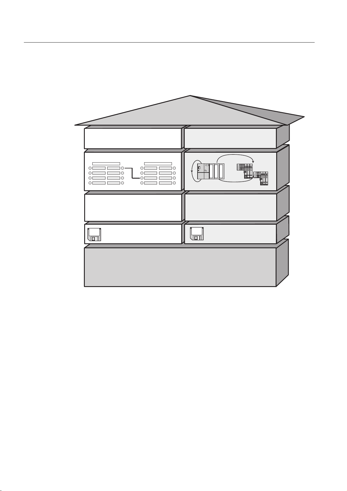
Configuring
4.11 Planning subnets
Extent of PROFINET IO and PROFINET CBA
PROFINET IO and CBA are two different views of programmable controllers on Industrial
Ethernet.
352),1(7
&RPSRQHQW9LHZ
352),1(7&%$
'LVWULEXWHG,QWHOOLJHQFH
3ODQWZLGH(QJLQHHULQJ
3&'
352),1(7&RPSRQHQW'HVFULSWLRQ
,2'DWD9LHZ
352),1(7,2
'LVWULEXWHG,2
1RUPDO,29LHZLQ67(3
*6'
*HQHULF6WDWLRQ'HVFULSWLRQ
2QH&DEOH,76WDQGDUGV6WDQGDUG$SSOLFDWLRQV
3URWRFROV1RQ57&RQWUROOHU
Figure 4-6 Extent of PROFINET IO and Component based Automation
Component based Automation divides the entire plant into various functions. These functions
are configured and programmed.
PROFINET IO provides you with a picture of the plant that is very similar to the view
obtained in PROFIBUS. You continue to configure and program the individual programmable
controllers.
Controllers in PROFINET IO and PROFINET CBA
You can also use some PROFINET IO controllers for PROFINET CBA.
The following list illustrates which PROFINET devices can adopt the function of a
PROFINET CBA or IO controller:
• Programmable controllers such as the S7-300 CPU 317-2 PN/DP
• CP 343-1 or CP 443-1 Advanced
S7-300, CPU 31xC and CPU 31x: Installation
4-52 Operating Instructions, Edition 08/2004, A5E00105492-05
Page 77

Configuring
4.11 Planning subnets
The following list illustrates which PROFINET devices can only adopt the function of a
PROFINET IO controller:
• PCs attached to PROFINET with a CP (for example CP 1616) and SOFTNET PROFINET
(for example CP 1612). With the CP 1616, the user program executes on the CP, with
SOFTNET PROFINET, it executes in the CPU of the PC.
• SIMOTION device for particularly strict real-time requirements.
PROFINET devices can only adopt the function of a PROFINET CBA controller, for example
PCs with a standard Ethernet interface and the WinLC software.
Proxy in PROFINET IO and PROFINET CBA
Proxies for PROFINET IO and proxies for PROFINET CBA are different.
In PROFINET IO, the proxy for PROFINET IO represents each connected PROFIBUS DP
slave as a PROFINET IO device on PROFINET.
In PROFINET CBA, the proxy for PROFINET CBA represents each connected PROFIBUS
DP slave as a component on PROFINET.
As a result, there are, for example, different IE/PB Links for PROFINET IO and PROFINET
CBA. Currently, you can only use a CPU 317-2 DP/PN as a proxy for PROFINET CBA.
Integrating Components and Devices
In Component based Automation, you integrate the components in an interconnection editor
(for example SIMATIC iMap). The components are described in a PCD file.
In PROFINET IO, you integrate the devices in an engineering system (for example STEP 7).
The components are described in a GSD file.
Connecting PROFIBUS Devices via an IE/PB Link
Remember that there is a separate proxy functionality for PROFINET I/O and PROFINET
CBA. With the IE/PB Link, this means that you must use different devices depending on the
system you are using.
Interaction of PROFINET CBA and PROFINET IO
PROFINET IO integrates field devices (IO devices) in PROFINET. The input and output data
of the IO devices is processed in the user program. The IO devices with their IO controller
themselves can, in turn, be part of a component in a distributed automation structure.
You configure communication between, for example, a CPU as IO controller and the IO
devices assigned to it as PROFINET IO in much the same way as a PROFIBUS DP master
system in STEP 7. You also create your user program in STEP 7. From this, you generate a
component in STEP 7.
You then configure communication between the components conveniently in SIMATIC iMAP.
S7-300, CPU 31xC and CPU 31x: Installation
Operating Instructions, Edition 08/2004, A5E00105492-05
4-53
Page 78

Configuring
4.11 Planning subnets
Note
Update Times for Cyclic Data Exchange
STEP 7 automatically calculates a time within which each PROFINET IO device completes
exchange of its user data with the corresponding IO controller: the update time.
Based on the existing hardware configuration and the resulting cyclic data traffic, STEP 7
automatically calculates an update time that you can extend manually.
If other cyclic services (for example PROFINET CBA) need to be taken into account in
addition to PROFINET IO: Set a percentage in STEP 7/HW Config that will be reserved for
PROFINET IO.
For more detailed information, refer to the STEP 7 online help.
Details on the Possible Uses of the Individual Products
For more information, refer to the documentation of the particular product.
4.11.3.5 PROFINET cable lengths and network expansion
Network expansion options are based on various factors (hardware design used, signal
propagation delay, minimum distance between data packets, etc.)
Prefabricated twisted-pair cord cables
Twisted-pair cables can be used in environments with low EMC loads and with transmission
lines up to 10 m. They employ the TP cord that is designed significantly thinner and more
flexible by using reduced shielding compared to industrial twisted-pair cables. The
connectors used in connecting industrial twisted-pair components are standardized RJ45
connectors and sub-D connectors.
S7-300, CPU 31xC and CPU 31x: Installation
4-54 Operating Instructions, Edition 08/2004, A5E00105492-05
Page 79

Configuring
4.11 Planning subnets
Product range for the RJ45 connection
The following prefabricated twisted-pair cables are available:
Table 4-25 Data for twisted-pair patch cables
Cable designation Application Available
lengths
TP Cord RJ45/RJ45 TP connecting cable with two RJ45
connectors.
TP XP cord RJ45/RJ45 Crossed TP cable with two RJ45
connectors.
TP cord 9/RJ45 TP cable with a 9-pin Sub-D connector
and an RJ45 connector.
TP XP cord 9/RJ45 Cross-over TP patch cable with 9-pin
sub-D connector and RJ45 connector.
TP patch cable
9-45/RJ45
TP XP patch cable
9-45/RJ45
TP XP patch cable 9/9 Cross-over TP patch cable for direct
TP patch cable
RJ45/15
TP XP patch cable
RJ45/15
TP patch cable with RJ45 connector and
sub-D connector, with 45° cable exit (for
OSM/ESM only)
Cross-over TP patch cable with RJ45
connector and sub-D connector with 45°
cable exit (for OSM/ESM only)
connection of two industrial Ethernet
network components with ITP interface,
with two 9-pin sub-D connectors
TP patch cable with 15-pin sub-D
connector and RJ45 connector.
Cross-over TP patch cable with 15-pin
sub-D connector and RJ45 connector
0.5 m
1.0 m
2.0 m
6.0 m
10.0 m
0.5 m
1.0 m
2.0 m
6.0 m
10.0 m
0.5 m
1.0 m
2.0 m
6.0 m
10.0 m
0.5 m
1.0 m
2.0 m
6.0 m
10.0 m
1.0 m 6XV1 850-2NH10
1.0 m 6XV1 850-2PH10
1.0 m 6XV1 850-2RH10
0.5 m
1.0 m
2.0 m
6.0 m
10.0 m
0.5 m
1.0 m
2.0 m
6.0 m
10.0 m
Order number
6XV1 850-2GE50
6XV1 850-2GH10
6XV1 850-2GH20
6XV1 850-2GH60
6XV1 850-2GN10
6XV1 850-2HE50
6XV1 850-2HH10
6XV1 850-2HH20
6XV1 850-2HH60
6XV1 850-2HN10
6XV1 850-2JE50
6XV1 850-2JH10
6XV1 850-2JH20
6XV1 850-2JH60
6XV1 850-2JN10
6XV1 850-2ME50
6XV1 850-2MH10
6XV1 850-2MH20
6XV1 850-2MH60
6XV1 850-2MN10
6XV1 850-2LE50
6XV1 850-2LH10
6XV1 850-2LH20
6XV1 850-2LH60
6XV1 850-2LNN10
6XV1 850-2SE50
6XV1 850-2SH10
6XV1 850-2SH20
6XV1 850-2SH60
6XV1 850-2SN10
S7-300, CPU 31xC and CPU 31x: Installation
Operating Instructions, Edition 08/2004, A5E00105492-05
4-55
Page 80

Configuring
4.11 Planning subnets
Reference
For detailed information on network configuration, refer to the Internet: SIMATIC NET:
Twisted Pair and Fiber-Optic Networks (6GK1970-1BA10-0AA0) at
http://www.siemens.com/automation/service&support.
See also
Connecting the PG to a node (Page 8-14)
Connecting the PG to several nodes (Page 8-15)
4.11.3.6 Connectors and other components for Ethernet
The selection of the bus cable, bus connector and other components for Ethernet (for
example, switches, etc.) depends on the intended application.
We offer a range of products covering a variety of applications for the installation of an
Ethernet connection.
Reference
•
SIMATIC NET: Twisted-Pair and Fiber-Optic Networks
(6GK1970-1BA10-0AA0)
S7-300, CPU 31xC and CPU 31x: Installation
4-56 Operating Instructions, Edition 08/2004, A5E00105492-05
Page 81

Configuring
4.11 Planning subnets
4.11.3.7 Example of a PROFINET Subnet
Example: Installation of a PROFINET subnet
The graphic illustrates the combination of corporate level and process control level via
industrial Ethernet. PCs in a classical office environment can be used to acquire data of the
process automation system.
Subnet 1Subnet 1 Subnet 2Subnet 2
Company network
INDUSTRIAL ETHERNET
Switch 1
Router
CPU
31x-2 PN/DP
Figure 4-7 Example of a PROFINET Subnet
Switch 2
CPU
31x-2 PN/DP
PG
Switch 3
31x-2 PN/DP
(DP SLAVE)
CPU
CPU
CPU
(DP master)
PROFIBUS
ET200
S7-300, CPU 31xC and CPU 31x: Installation
Operating Instructions, Edition 08/2004, A5E00105492-05
4-57
Page 82

Configuring
4.11 Planning subnets
Installation guidelines
PROFINET allows you to set up a high-performance and continuous communication system.
You can further increase performance by using the following installation guidelines.
• Interconnect a router between the office network and the PROFINET system. Use the
router to define access privileges for your PROFINET system.
• Set up your PROFINET in a star architecture where this is useful (for example: in a switch
cabinet).
• Keep the number of switches low. This increases clarity of your PROFINET system
architecture.
• Connect your programming device (PG) close to the communication partner (for example:
connect the PG and the communication partner to the same switch).
• Modules with PROFINET interfaces may only be operated in LANs where all nodes are
equipped with SELV/PELV power supplies or protection systems of equal quality.
• A data transfer device that ensures this safety must be specified for the coupling to the
WAN.
Reference
For detailed information on Industrial Ethernet networks or network components, refer to:
• the Internet URL http://www.siemens.com/automation/service&support.
• The STEP 7 Online Help. There you can also find further information on IP address
assignment.
• The Communication with SIMATIC (EWA 4NEB 710 6075-01) manual
• The SIMATIC NET manual: Twisted-Pair and Fiber Optic Networks
(6GK1970-1BA10-0AA0)
S7-300, CPU 31xC and CPU 31x: Installation
4-58 Operating Instructions, Edition 08/2004, A5E00105492-05
Page 83
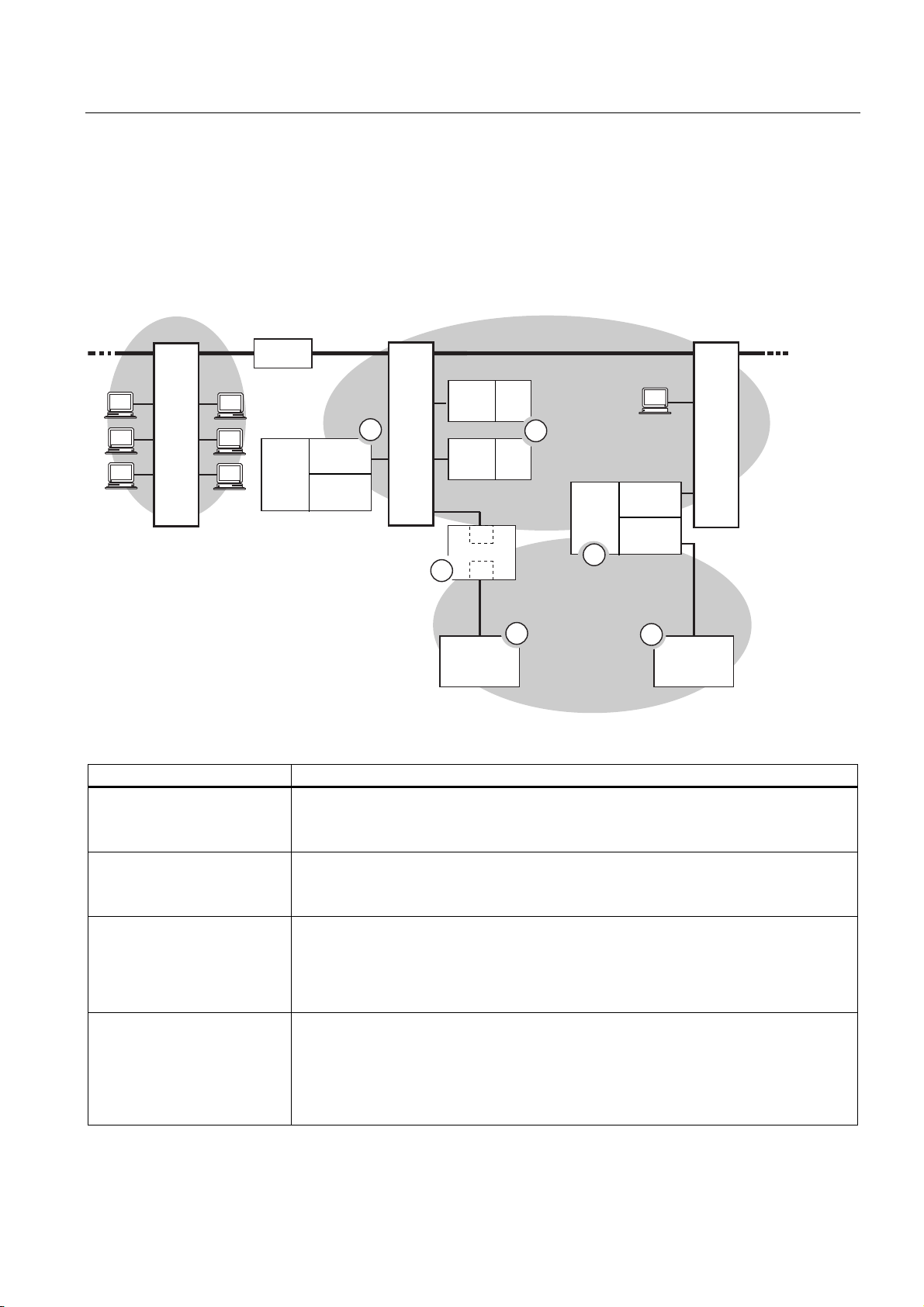
Configuring
4.11 Planning subnets
4.11.3.8 Example of a PROFINET IO system
Extended Functions of PROFINET IO
The figure below shows you the new functions of PROFINET IO
&RPSDQ\1HWZRUN
6ZLWFK
5RXWHU
&38
[
31'3
,2
&RQWUROOHU
'3
0DVWHU
,QGXVWULDO(WKHUQHW
,2
'HYLFH
1
6ZLWFK
,2
'HYLFH
6
'36/$9(
,(
,(3%/LQN
3%
(7
(7
6
(7
6
5
2
&38
[
31'3
3
352),%86
3*
6ZLWFK
,2
&RQWUROOHU
'3
0DVWHU
4
(7
'36/$9(
The figure shows The figure shows the communication path
The interconnection of the
company network with field
level
The interconnection between
the automation system and
field level
The IO controller of the CPU
31x-2 PN/DP (1) controls the
nodes connected to the
Industrial Ethernet and
PROFIBUS directly
A CPU can be both IO
controller and DP master
From PCs in your company network, you can access devices at the field level
Example:
• PC — Switch 1 — Router — Switch 2 — CPU 31x-2 PN/DP (1).
You can, of course, also access other areas in Industrial Ethernet from a field PG.
Example:
• PG — Switch 3 — Switch 2 — to an IO device of ET 200S (2).
At this point, you see the enhanced IO feature between the IO controller and IO device(s)
on Industrial Ethernet:
• The CPU 31x-2 PN/DP (1) is the IO controller for one of the ET 200S (2) IO devices.
• The CPU 31x-2 PN/DP (1) is also the IO controller for the ET 200 (DP slave) (5) via
the IE/PB Link (6).
Here, you can see that a CPU can be both IO controller for an IO device as well as DP
master for a DP slave:
• The CPU 31x-2 PN/DP (3) is the IO controller for the other ET 200S (2) IO device.
CPU 31x-2 PN/DP (3) — Switch 3 — Switch 2 — ET 200S (2)
• The CPU 31x-2 PN/DP (3) is the DP master for a DP slave (4). The DP slave (4) is
assigned locally to the CPU (3) and is not visible on the Industrial Ethernet.
S7-300, CPU 31xC and CPU 31x: Installation
Operating Instructions, Edition 08/2004, A5E00105492-05
4-59
Page 84

Configuring
4.11 Planning subnets
Requirements
• CPUs as of Firmware 2.3.0 (for example CPU 315-2 PN/DP)
• STEP 7, as of Version 5.3 + Service Pack 1
Reference
For information on PROFINET, refer to:
• the
• in the programming manual
System Description PROFINET
From PROFIBUS DP to PROFINET.
provides a comprehensive overview of the new PROFINET blocks and system status
lists.
4.11.4 Routed network transitions
Example: PG access to remote networks (routing)
A CPU with several interfaces can also serve as a router for intercommunication with
different subnets. With a PG you can access all modules on local and remote networks.
Requirements:
• STEP 7 Version 5.0 or higher.
Note: For STEP 7 requirements with respect to the CPUs used, refer to the technical
specifications.
• Assign the PG/PC to a network in your STEP 7 project (SIMATIC Manager, assigning a
PG/PC).
• The various networks are interconnected using modules with routing functions.
This manual also
• After you configured all networks in NETPRO, initiated a new compilation for all stations,
and then download the configuration to all modules with routing function. This also
applies to all changes made in the network.
All routers therefore know all paths to a destination station.
S7-300, CPU 31xC and CPU 31x: Installation
4-60 Operating Instructions, Edition 08/2004, A5E00105492-05
Page 85

Configuring
4.11 Planning subnets
Access to remote networks
PG/PC 3
S7-400
PS
CPU
CPU
CPU 416
S7-400
PS
CPU 417
CPU
MPI (2)
MPI (1)
S7-300
PS
CPU
CPU
31x-2 DP
S7-300
PS
CPU
CPU
CPU
PG/PC 1
PROFIBUS DP
ET200
CPU
PG/PC 2
Figure 4-8 Access to remote networks
Example 1
To access the CPU 31x-2 DP using PG/PC 1:
PG/PC 1 - MPI network (1) - CPU 417 as router - PROFIBUS network (3) - CPU 31x-2 DP
Example 2
To access the the S7-300 CPU (on the right in the figure) using PG/PC 2:
PG/PC 2 - PROFIBUS network (3)- CPU 31x-2 DP as router - MPI network (2) - S7-300 CPU
Example 3
To access the 416 CPU using PG/PC 3:
PG/PC 3 - MPI network (2) - CPU 31x-2 DP as router - PROFIBUS network (3)- CPU 417 as
router - MPI network (1) - CPU 416
Note
Only for CPUs with DP interface:
If these CPUs are operated as I-slaves and you want to use routing functionality, set the
Commissioning / Debug Mode / Routing check box in the DP Interface for DP Slave dialog
box in STEP 7.
S7-300, CPU 31xC and CPU 31x: Installation
Operating Instructions, Edition 08/2004, A5E00105492-05
4-61
Page 86

Configuring
4.11 Planning subnets
Information on routing can be found ...
•
CPU Data Reference Manual
for your CPU
• In the
Communication with SIMATIC
4.11.5 Point-to-point (PtP)
Availability
CPUs with a “PtP“ name suffix are equipped with a PtP X2 interface.
Properties
Using the PtP interface of your CPU, you can connect external devices with serial interface.
You can operate such a system at transmission rates up to 19.2 kbps in full duplex mode
(RS 422), and up to 38.4 kbps in half duplex mode (RS 485).
Transmission rate
• Half duplex: 38.4 kbps
• Full duplex: 19.2 kbps
Driver
PtP communication drivers installed in those CPUs:
manual.
• ASCII drivers
• 3964(R) Protocol
• RK 512 (only CPU 314C-2 PtP)
Devices capable of PtP communication
Devices equipped with a serial port, for example, barcode readers, printers, etc.
Reference
CPU 31xC: Technological functions
manual
S7-300, CPU 31xC and CPU 31x: Installation
4-62 Operating Instructions, Edition 08/2004, A5E00105492-05
Page 87

Configuring
4.11 Planning subnets
4.11.6 Actuator/sensor interface (ASI)
Actuator/Sensor Interface (ASI)
Implementation using communication processors (CP).
The ASI, or Actuator/Sensor Interface, represents a subnet system on the lowest process
level for automation systems. It is designed especially for networking digital sensors and
actuators. The maximum data volume is 4 bits per slave station.
S7-300 CPUs require communication processor for the ASI connection.
S7-300, CPU 31xC and CPU 31x: Installation
Operating Instructions, Edition 08/2004, A5E00105492-05
4-63
Page 88

Configuring
4.11 Planning subnets
S7-300, CPU 31xC and CPU 31x: Installation
4-64 Operating Instructions, Edition 08/2004, A5E00105492-05
Page 89

Installing
5.1 Installing an S7-300
Here we will explain the steps required for the mechanical assembly of an S7-300.
Open components
Note
Note the installation guidelines and notes on safety in this manual when mounting,
commissioning and operating S7-300 systems.
S7-300 modules are "Open Components" according to IEC 61131-2 and EC directive
73/23/EEC (Low-Voltage directive), and to UL/CSA Approval an "open type".
5
In order to conform with specifications on safe operation relating to mechanical strength,
inflammability, stability and touch-protection, the following alternative installation modes are
prescribed:
• Installation in a suitable cubicle
• Installation in a suitable cabinet
• Installation in an appropriately equipped and closed operating area
Access to these areas must only be possible with a key or tool. Only trained or authorized
personnel is allowed access to these cubicles, cabinets or electrical operating rooms.
S7-300, CPU 31xC and CPU 31x: Installation
Operating Instructions, Edition 08/2004, A5E00105492-05
5-1
Page 90

Installing
5.1 Installing an S7-300
Accessories included
Installation accessories are included with the module package. The appendix contains a list
of accessories and spare parts together with the corresponding order numbers.
Table 5-1 Module accessories
Module Accessories included Explanation
1 x Slot number label For assigning slot numbers CPU
Inscription labels for the MPI address and Firmware
Version (all CPUs)
for labeling of integrated inputs
and outputs (CPU 31xC only)
Tip: Templates for labeling strips
are available on the Internet at
http://www.ad.siemens.de/csinfo,
under article ID 11978022.
Signal module (SM)
Function Module (FM)
Communication module (CP)
Interface module (IM) 1 x Slot number label (only
1 Bus connector For electrical interconnection of
modules
1 Labeling strip For labeling module I/O
Tip: Templates for labeling strips
are available on the Internet at
http://www.ad.siemens.de/csinfo
under article ID 11978022.
1 Bus connector For electrical interconnection of
modules
1 Inscription label
(only CP 342-2)
IM 361 and IM 365)
For labeling the AS interface
connector
Tip: Templates for labeling strips
are available on the Internet at
http://www.ad.siemens.de/csinfo
under article ID 11978022.
For assigning slot numbers on
racks 1 to 3
S7-300, CPU 31xC and CPU 31x: Installation
5-2 Operating Instructions, Edition 08/2004, A5E00105492-05
Page 91

Installing
5.2 Installing the mounting rail
Tools required and material
To install the S7-300, you require the tools and materials listed in the table below.
Table 5-2 Installation tools and materials
You require ... for ...
cutting the 2 m rail to length commonly available tool
scribing and drilling holes on the 2 m rail commonly available tool, 6.5 mm diameter drill bit
screw-mounting the rail wrench or screwdriver, matching the selected
fixing screws
diverse M6 screws (length depends on the place
of installation) with nuts and spring lock washers
screw-fastening the modules on the rail screwdriver with 3.5 mm blade width (cylindrical
design)
pulling out the grounding slide contact to achieve
ungrounded state
screwdriver with 3.5 mm blade width (cylindrical
design)
5.2 Installing the mounting rail
Mounting rail versions available
• Ready-to-use, four standard lengths (with 4 holes for fixing screws and 1 ground
conductor bolt)
• One meter mounting rail
May be shortened to any special length. Supplied without holes for fixing screws and
without ground conductor bolt.
Requirements
Prepare the 2 m mounting rail for installation.
S7-300, CPU 31xC and CPU 31x: Installation
Operating Instructions, Edition 08/2004, A5E00105492-05
5-3
Page 92
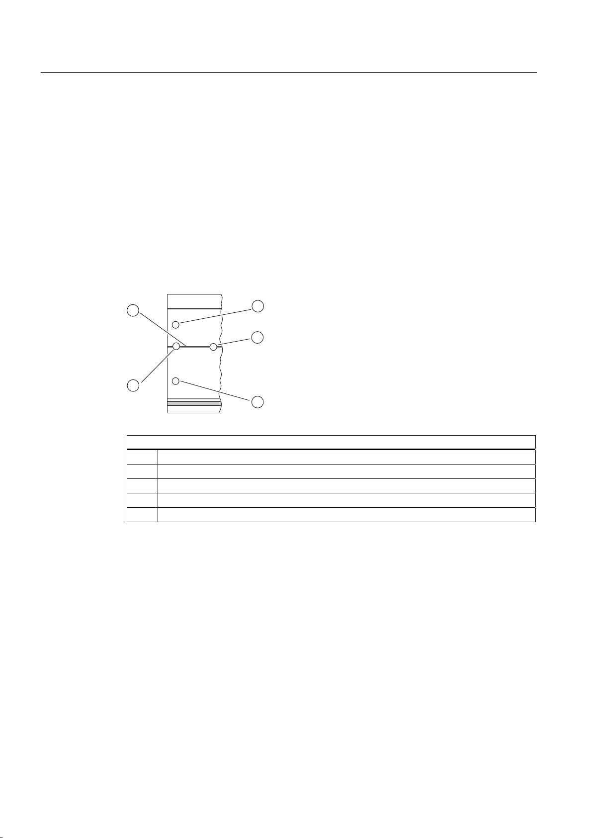
Installing
5.2 Installing the mounting rail
Preparing the 2 m mounting rail for installation
1. Cut the 2 m mounting rail to the required length.
2. Mark out:
– four bores for the fixing screws (for dimensions, refer to "Dimensions for fixing holes")
– one hole for the protective conductor bolt.
3. If the length of your rail exceeds 830 mm, you must stabilize it by providing additional
holes for fixing it with more screws.
Mark out these holes along the groove in the middle section of the rail (see the Figure
below). The pitch should be approx. 500 mm.
4. Drill the marked holes, bore diameter = 6.5
5. Mount an M6 bolt for fixing the ground conductor.
+0,2
mm for M6 screws.
2
3
4
1
5
Key to numbers in the figure
(1) Hole for the ground conductor bolt
(2) Groove for drilling additional holes for mounting screws
(3) Hole for the mounting screw
(4) Additional hole for mounting screw
(5) Hole for the mounting screw
S7-300, CPU 31xC and CPU 31x: Installation
5-4 Operating Instructions, Edition 08/2004, A5E00105492-05
Page 93

Installing
_
5.2 Installing the mounting rail
Dimension of the mounting holes
The fixing hole dimensions for the mounting rail are shown in the table below..
Table 5-3 Mounting holes for rails
"Standard" rail 2 m mounting rail
32.5 mm
57.2 mm
a
b
Length of rail Dimension a Dimension b
160 mm 10 mm 140 mm
482.6 mm 8.3 mm 466 mm
530 mm 15 mm 500 mm
830 mm 15 mm 800 mm
Fixing screws
To fix the mounting rails you can use the following types of screws:
For ... you can use ... description
outer fixing screws
additional fixing screws
(only 2 m mounting rail)
32.5 mm
57.2 mm
approx.
500 mm
_
15 mm
_
–
cylindrical head screw M6 to
ISO 1207/ISO 1580
(DIN 84/DIN 85)
M6 hexagonal head screw to
ISO 4017 (DIN 4017)
cylindrical head screw M6 to
ISO 1207/ISO 1580
(DIN 84/DIN 85)
approx.
500 mm
15 mm
_
Choose a suitable screw length
for your assembly.
You also need size 6.4 washers
to ISO 7092 (DIN 433)
S7-300, CPU 31xC and CPU 31x: Installation
Operating Instructions, Edition 08/2004, A5E00105492-05
5-5
Page 94

Installing
SIEMEN S
5.2 Installing the mounting rail
Installing the mounting rail
1. Install the mounting rails so that sufficient space is available for installing modules and to
allow heat dissipation (clearance of at least 40 mm above and below the modules. See
the figure below).
2. Mark up the mounting holes on the mounting surface. Drill the holes,
diameter = 6.5
+0.2
mm.
3. Screw the rail (M6 screws) onto the mounting surface.
Note
Always make sure of a low-impedance contact between the rail and a mounting surface,
if the latter is a grounded metal panel or equipment mounting panel. On varnished or
anodized metals, for instance, use a suitable contacting agent or contact washers.
The figure below shows the clearance required for the installation of an S7-300.
40 mm
20
mm
40 mm
20
mm
S7-300, CPU 31xC and CPU 31x: Installation
5-6 Operating Instructions, Edition 08/2004, A5E00105492-05
Page 95

Installing
5.3 Mounting modules onto the rail
5.3 Mounting modules onto the rail
Requirements for module installation
• The configuration of the automation system is completed.
• The mounting rail is installed.
Mounting order of the modules
Hang the modules onto the rail, starting at the left and in the following order:
1. Power supply module
2. CPU
3. SMs, FMs, CPs, IMs
Note
Please check before you insert any SM 331 analog input modules whether you have to
reposition the measuring range submodules at the side of the module. For further
information, refer to chapter 4, "Analog Modules" in your
Module Data
Reference Manual.
Note
When installing an S7-300 system with ungrounded reference potential, make the
relevant settings on the CPU. You ideally do so before you mount any modules onto the
rail.
S7-300, CPU 31xC and CPU 31x: Installation
Operating Instructions, Edition 08/2004, A5E00105492-05
5-7
Page 96

Installing
5.3 Mounting modules onto the rail
Installation steps
The various steps in module installation are explained below.
1. Plug the bus connectors into the CPU and SMs
/ FMs / CPs / IMs.
Except for the CPU, each module is supplied
with a bus connector.
• Always start at the CPU when you plug in
the bus connectors. Remove the bus
connector from the "last" module of the
assembly.
• Plug the bus connectors into the other
modules.
The "last" module does not receive a bus
connector.
CPU
2. Add all modules to the rail in the specified order
(1), slide them up to the module on the left (2),
then swing them down (3).
3. Screw-tighten the modules.
CPU
CPU
1
2
3
See also
Configuring an S7-300 with ungrounded reference potential (not CPU 31xC) (Page 4-17)
S7-300, CPU 31xC and CPU 31x: Installation
5-8 Operating Instructions, Edition 08/2004, A5E00105492-05
Page 97

Installing
5.4 Labeling the modules
5.4 Labeling the modules
Slot numbers Assignment
You should assign a slot number to each one of the mounted modules, thus making it easier
to assign the modules in the configuration table in STEP 7. The table below shows the slot
number assignment.
Table 5-4 Slot numbers for S7 modules
Slot number Module Comment
1 Power supply (PS) –
2 CPU –
3 Interface module (IM) to the right of the CPU
4 1. Signal module (SM) to the right of the CPU or IM
5 2. Signal module (SM) –
6 3. Signal module (SM) –
7 4. Signal module (SM) –
8 5. Signal module (SM) –
9 6. Signal module (SM) –
10 7. Signal module (SM) –
11 8. Signal module (SM) –
S7-300, CPU 31xC and CPU 31x: Installation
Operating Instructions, Edition 08/2004, A5E00105492-05
5-9
Page 98
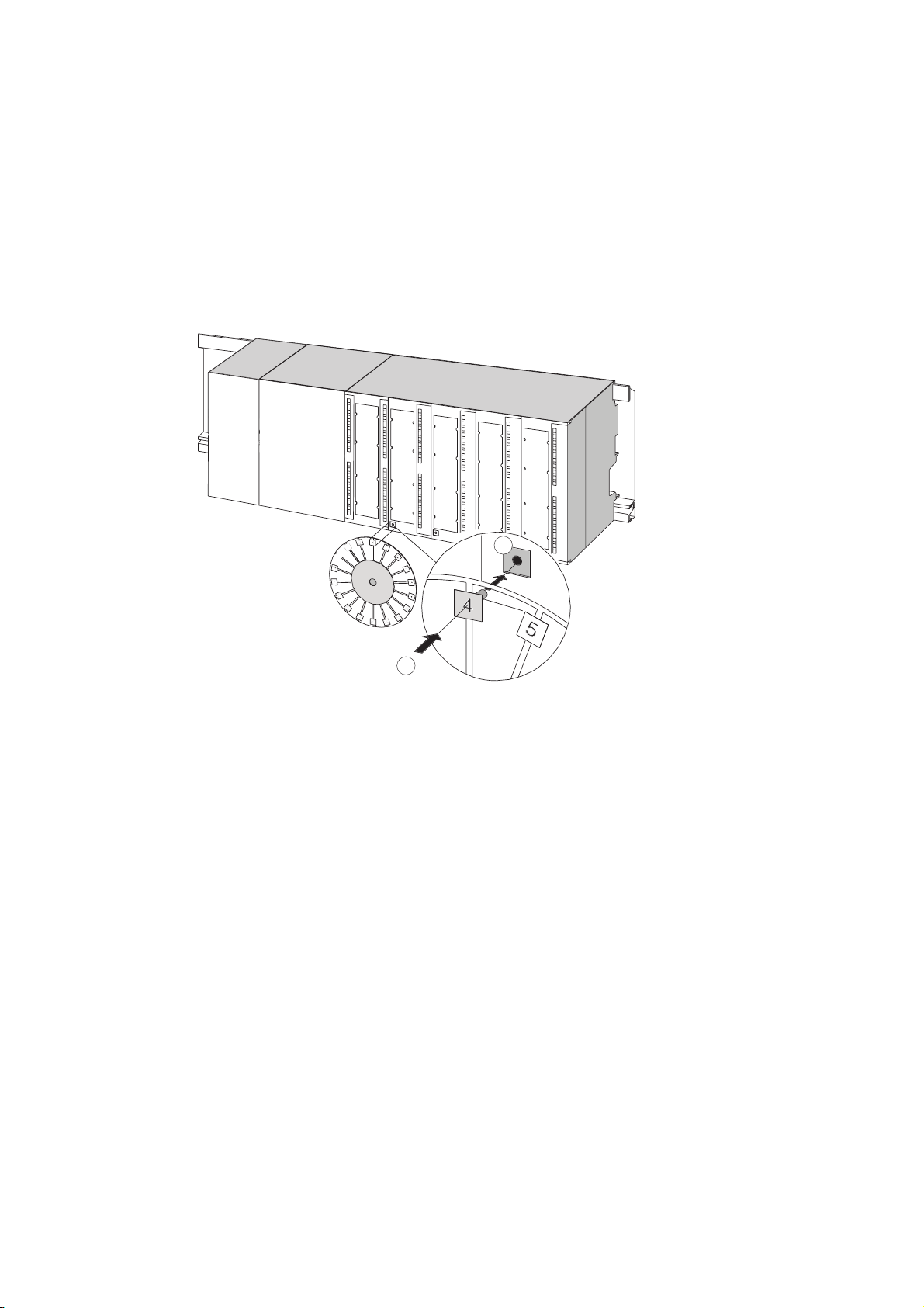
Installing
5.4 Labeling the modules
Slot numbers Clipping the slot numbers onto the modules
1. Hold the corresponding slot number in front of the relevant module.
2. Insert the pin into the opening on the module (1).
3. Press the slot number into the module (2). The slot number breaks off from the wheel.
The figure below illustrates this procedure. The slot number labels are included with the
CPU.
PS
CPU
1
2
S7-300, CPU 31xC and CPU 31x: Installation
5-10 Operating Instructions, Edition 08/2004, A5E00105492-05
Page 99

Wiring
6.1 Requirements for wiring the S7-300
This chapter
Describes the requirements for wiring the PS, CPU and front connectors.
Accessories required
The following accessories are required for wiring the S7-300.
Table 6-1 Wiring accessories
Accessories Description
Front connectors for connecting the sensors / actuators of the
Labeling strips for labeling the module I/Os
Shielding contact element, shielding terminals
(matching the shielding diameter)
6
system to the S7-300
for connecting cable shielding
Tools and material required
Tools and materials required for wiring the S7-300.
Table 6-2 Tools and material for wiring
To ... you need ...
Connect the protective conductor to the rail Wrench (size 10)
Adjust the power supply module to mains voltage Screwdriver with a blade width of 4.5 mm
Wire the power supply module and the CPU Screwdriver with a 3.5-mm blade, side-cutters,
S7-300, CPU 31xC and CPU 31x: Installation
Operating Instructions, Edition 08/2004, A5E00105492-05
Protective conductor cable (crosssection ≥ 10 mm
M6 nut, washer, spring lock washer
stripping tool
Flexible cable, for example, sheathed flexible
cable 3 x 1.5 mm
Wire end ferrules to DIN 46228
2
) with M6 cable lug
2
6-1
Page 100

Wiring
6.1 Requirements for wiring the S7-300
To ... you need ...
Wire the front connector Screwdriver with a 3.5-mm blade, side-cutters,
stripping tool
Flexible cables, 0.25 mm
2
to 0.75/1.5 mm2
Shielded cables as required
Wire end ferrules to DIN 46228
Wiring conditions for PS and CPU
Table 6-3 Wiring conditions for PS and CPU
Connectable cables to PS and CPU
Solid conductors No
Flexible conductors
• without wire end ferrule
• With wire end ferrule
Number of conductors per terminal 1 or 2, up to 1.5 mm2 (total) in a common wire
Diameter of the conductor insulation max. 3.8 mm
Stripped length 11 mm
Wire end ferrules to DIN 46228
• without insulating collar
• with insulating collar
0.25 mm
0.25 mm
2
to 2.5 mm2
2
to 1.5 mm2
end ferrule
Design A, 10 mm to 12 mm length
Design E, up to 12 mm length
Wiring conditions for front connectors
Table 6-4 Wiring conditions for front connectors
Connectable cables
Solid conductors No No
Flexible conductors
• without wire end ferrule
• with wire end ferrule
Number of conductors per
terminal
Diameter of the conductor
insulation
Stripped length 6 mm 6 mm
Wire end ferrules to DIN
46228
• without insulating collar
• with insulating collar
Front connectors
20-pole 40-pole
0.25 mm
0.25 mm
2
to 1.5 mm2
2
to 1.5 mm2
0.25 mm
0.25 mm
• Mains feed 1.5 mm
1 or 2, up to 1.5 mm2 (total) in a
common wire end ferrule
max. 3.1 mm
1 or 2, up to 0.75 mm2 (total) in a
common wire end ferrule
• max. 2.0 mm for 40-pole
cables
• max. 3.1 mm for 20-pole
cables
Design A, 5 mm to 7 mm length
Design E, up to 6 mm length
Design A, 5 mm to 7 mm length
Design E, up to 6 mm length
2
to 0.75 mm2
2
to 0.75 mm2
2
S7-300, CPU 31xC and CPU 31x: Installation
6-2 Operating Instructions, Edition 08/2004, A5E00105492-05
 Loading...