

Page 1

Preface, Contents
SIMATIC
S7-200
Programmable Controller,
CPU 210
System Manual
Installing the CPU 210
Installing and Using the
STEP 7-Micro/WIN Version 2.0
Software
Getting Started with a Sample
Program
Basic Concepts for
Programming the CPU 210
Instruction Set
Appendix
CPU 210 Data Sheets
Special Memory (SM)
1
2
3
4
5
A
B
C79000-G7076-C235-01
Error Handling and Error Codes
Converting STEP 7-Micro/DOS
Files to STEP 7-Micro/WIN Files
Execution Times for STL
Instructions
CPU 210 Order Numbers
Index
C
D
E
F
Page 2

Safety Guidelines
!
!
!
This manual contains notices which you should observe to ensure your own personal safety, as well as to
protect the product and connected equipment. These notices are highlighted in the manual by a warning
triangle and are marked as follows according to the level of danger:
Danger
indicates that death, severe personal injury or substantial property damage will result if proper precautions are
not taken.
Warning
indicates that death, severe personal injury or substantial property damage can result if proper precautions are
not taken.
Caution
indicates that minor personal injury or property damage can result if proper precautions are not taken.
Note
draws your attention to particularly important information on the product, handling the product, or to a particular
part of the documentation.
Qualified Personnel
Correct Usage
The device/system may only be set up and operated in conjunction with this manual.
Only qualified personnel should be allowed to install and work on this equipment. Qualified persons are
defined as persons who are authorized to commission, to ground, and to tag circuits, equipment, and systems in accordance with established safety practices and standards.
Note the following:
Warning
!
Trademarks
The reproduction, transmission or use of this document or its
contents is not permitted without express written authority.
Offenders will be liable for damages. All rights, including rights
created by patent grant or registration of a utility model or design, are
reserved.
Siemens Energy & Automation, Inc.
3333 Old Milton Parkway
Alpharetta, GA 30202
This device and its components may only be used for the applications described in the catalog or the technical
description, and only in connection with devices or components from other manufacturers which have been
approved or recommended by Siemens.
This product can only function correctly and safely if it is transported, stored, set up, and installed correctly, and
operated and maintained as recommended.
SIMATICR and SINECR are registered trademarks of SIEMENS AG.
Third parties using for their own purposes any other names in this document which refer to
trademarks might infringe upon the rights of the trademark owners.
Disclaimer of LiabilityCopyright E Siemens SE&A 1997 All rights reserved
We have checked the contents of this manual for agreement with the
hardware and software described. Since deviations cannot be
precluded entirely , we cannot guarantee full agreement. However ,
the data in this manual are reviewed regularly and any necessary
corrections included in subsequent editions. Suggestions for
improvement are welcomed.
Technical data subject to change.
E Siemens SE&A 1997
Siemens Energy & Automation
6ES7 298-8EA00-8BH0
S7-200 Programmable Controller, CPU 210
Page 3

Preface
Purpose
The CPU 210 is an addition to the S7-200 series micro-programmable logic controllers
(Micro PLCs). Its compact design, low cost, and powerful instruction set make the CPU 210
a perfect solution for controlling small applications. The selection of voltage options provides
you with the flexibility you need to solve your automation problems.
SIMA TIC S7-200 CPU 210 Programmable Controller System Manual
The
information about installing and programming the CPU 210 and the program development
station (PDS 210). This manual also includes descriptions and examples for the
programming instructions, typical execution times for the instructions, and the data sheets for
the CPU 210 and related equipment.
Audience
This manual is designed for engineers, programmers, installers, and electricians who have a
general knowledge of programmable logic controllers.
Scope of the Manual
The information contained in this manual pertains in particular to the following products:
S CPU 210 and the PDS 210
S STEP 7-Micro/WIN version 2.0 programming software
provides
How to Use This Manual
If you are a first-time (novice) user of S7-200 Micro PLCs, you should read the entire manual.
If you are an experienced user, refer to the table of contents or index to find specific
information.
The manual is organized in the following topics:
S “Installing the CPU 210” (Chapter 1) provides an overview of some of the features of the
equipment and the procedures, dimensions, and basic guidelines for installing the
CPU 210.
S “Installing and Using the STEP 7-Micro/WIN V ersion 2.0 Software” (Chapter 2) describes
how to install the programming software. It also provides a basic explanation about the
features of the software.
S “Getting Started with a Sample Program” (Chapter 3) helps you enter a sample program,
using the STEP 7-Micro/WIN software.
S “Basic Concepts for Programming the CPU 210” (Chapter 4) provides information about
how the CPU 210 processes data and executes a program.
S “Instruction Set” (Chapter 5) provides explanations and examples of the programming
instructions used by the CPU 210.
S7-200 Programmable Controller, CPU 210
C79000-G7076-C235-01
iii
Page 4

Preface
Additional information (such as the equipment data sheets, error code descriptions and
execution times) are provided in the appendices.
Additional Assistance
For assistance in answering technical questions, for training on this product, or for ordering,
contact your Siemens distributor or sales office.
iv
S7-200 Programmable Controller, CPU 210
C79000-G7076-C235-01
Page 5

Contents
1 Installing the S7-200 CPU 210
1.1 Product Overview 1-2. . . . . . . . . . . . . . . . . . . . . . . . . . . . . . . . . . . . . . . . . . . . . . . . . . . . . . .
Equipment Requirements 1-2. . . . . . . . . . . . . . . . . . . . . . . . . . . . . . . . . . . . . . . . . . . . . . . .
Features of the CPU 210 1-3. . . . . . . . . . . . . . . . . . . . . . . . . . . . . . . . . . . . . . . . . . . . . . . .
1.2 Pre-installation Considerations 1-4. . . . . . . . . . . . . . . . . . . . . . . . . . . . . . . . . . . . . . . . . . .
Installation Configuration 1-4. . . . . . . . . . . . . . . . . . . . . . . . . . . . . . . . . . . . . . . . . . . . . . . . .
Clearance Requirements for Installing a CPU 210 1-4. . . . . . . . . . . . . . . . . . . . . . . . . . .
DIN Rail Requirements 1-5. . . . . . . . . . . . . . . . . . . . . . . . . . . . . . . . . . . . . . . . . . . . . . . . . .
Panel-Mounting Dimensions 1-5. . . . . . . . . . . . . . . . . . . . . . . . . . . . . . . . . . . . . . . . . . . . . .
1.3 Installing a CPU 210 1-6. . . . . . . . . . . . . . . . . . . . . . . . . . . . . . . . . . . . . . . . . . . . . . . . . . . .
Mounting a CPU 210 on a Panel 1-6. . . . . . . . . . . . . . . . . . . . . . . . . . . . . . . . . . . . . . . . . .
Installing a CPU 210 on a DIN Rail 1-6. . . . . . . . . . . . . . . . . . . . . . . . . . . . . . . . . . . . . . . .
Installing a CPU 210 in a Panel Box 1-7. . . . . . . . . . . . . . . . . . . . . . . . . . . . . . . . . . . . . . .
1.4 Installing the Field Wiring 1-8. . . . . . . . . . . . . . . . . . . . . . . . . . . . . . . . . . . . . . . . . . . . . . . .
General Guidelines 1-8. . . . . . . . . . . . . . . . . . . . . . . . . . . . . . . . . . . . . . . . . . . . . . . . . . . . .
Grounding and Circuit Referencing Guidelines for Using Isolated Circuits 1-9. . . . . . .
Using the Optional Field Wiring Connector 1-10. . . . . . . . . . . . . . . . . . . . . . . . . . . . . . . . .
Guidelines for AC Installation 1-10. . . . . . . . . . . . . . . . . . . . . . . . . . . . . . . . . . . . . . . . . . . . .
Guidelines for DC Installation 1-10. . . . . . . . . . . . . . . . . . . . . . . . . . . . . . . . . . . . . . . . . . . . .
1.5 Using Suppression Circuits 1-12. . . . . . . . . . . . . . . . . . . . . . . . . . . . . . . . . . . . . . . . . . . . . . .
Protecting DC Transistors 1-12. . . . . . . . . . . . . . . . . . . . . . . . . . . . . . . . . . . . . . . . . . . . . . . .
Protecting Relays Controlling DC Power 1-12. . . . . . . . . . . . . . . . . . . . . . . . . . . . . . . . . . .
2 Installing and Using the STEP 7-Micro/WIN Version 2.0 Software
2.1 Installing the STEP 7-Micro/WIN Version 2.0 Software 2-2. . . . . . . . . . . . . . . . . . . . . . .
Pre-installation Instructions 2-2. . . . . . . . . . . . . . . . . . . . . . . . . . . . . . . . . . . . . . . . . . . . . . .
Installation Instructions for Windows 3.1 2-2. . . . . . . . . . . . . . . . . . . . . . . . . . . . . . . . . . .
Installation Instructions for Windows 95 2-2. . . . . . . . . . . . . . . . . . . . . . . . . . . . . . . . . . . .
Troubleshooting the Installation 2-2. . . . . . . . . . . . . . . . . . . . . . . . . . . . . . . . . . . . . . . . . . .
2.2 Establishing Communication with the PDS 210 2-3. . . . . . . . . . . . . . . . . . . . . . . . . . . . .
Connecting Your Computer to the PDS 210 for PPI Communications 2-3. . . . . . . . . . .
Setting Up the Communications Parameters 2-4. . . . . . . . . . . . . . . . . . . . . . . . . . . . . . . .
2.3 Configuring the Preferences for STEP 7-Micro/WIN 2-5. . . . . . . . . . . . . . . . . . . . . . . . . .
2.4 Creating and Saving a Project 2-6. . . . . . . . . . . . . . . . . . . . . . . . . . . . . . . . . . . . . . . . . . . .
Creating a New Project 2-6. . . . . . . . . . . . . . . . . . . . . . . . . . . . . . . . . . . . . . . . . . . . . . . . . .
Saving a Project 2-6. . . . . . . . . . . . . . . . . . . . . . . . . . . . . . . . . . . . . . . . . . . . . . . . . . . . . . . .
S7-200 Programmable Controller, CPU 210
C79000-G7076-C235-01
v
Page 6

Contents
2.5 Creating a Program 2-7. . . . . . . . . . . . . . . . . . . . . . . . . . . . . . . . . . . . . . . . . . . . . . . . . . . . .
Entering Your Program in Ladder 2-7. . . . . . . . . . . . . . . . . . . . . . . . . . . . . . . . . . . . . . . . .
Entering Your Program in Statement List 2-8. . . . . . . . . . . . . . . . . . . . . . . . . . . . . . . . . . .
Compiling the Program 2-8. . . . . . . . . . . . . . . . . . . . . . . . . . . . . . . . . . . . . . . . . . . . . . . . . .
Viewing a Program in Ladder or Statement List 2-9. . . . . . . . . . . . . . . . . . . . . . . . . . . . .
2.6 Downloading A Program 2-10. . . . . . . . . . . . . . . . . . . . . . . . . . . . . . . . . . . . . . . . . . . . . . . . .
Downloading the Program to the PDS 210 2-10. . . . . . . . . . . . . . . . . . . . . . . . . . . . . . . . .
Copying Your Program to the Memory Cartridge 2-1 1. . . . . . . . . . . . . . . . . . . . . . . . . . . .
Transporting the Program to the CPU 210 2-11. . . . . . . . . . . . . . . . . . . . . . . . . . . . . . . . . .
2.7 Using Symbolic Addressing 2-13. . . . . . . . . . . . . . . . . . . . . . . . . . . . . . . . . . . . . . . . . . . . . .
Guidelines for Entering Symbolic Addresses 2-13. . . . . . . . . . . . . . . . . . . . . . . . . . . . . . . .
Starting the Symbol Table Editor 2-13. . . . . . . . . . . . . . . . . . . . . . . . . . . . . . . . . . . . . . . . . .
Editing Functions within the Symbol Table 2-14. . . . . . . . . . . . . . . . . . . . . . . . . . . . . . . . . .
Sorting Table Entries 2-14. . . . . . . . . . . . . . . . . . . . . . . . . . . . . . . . . . . . . . . . . . . . . . . . . . . .
Displaying the Symbolic Addresses 2-14. . . . . . . . . . . . . . . . . . . . . . . . . . . . . . . . . . . . . . .
2.8 Using the Status Chart 2-15. . . . . . . . . . . . . . . . . . . . . . . . . . . . . . . . . . . . . . . . . . . . . . . . . .
Reading and Writing Variables with the Status Chart 2-15. . . . . . . . . . . . . . . . . . . . . . . . .
Editing Addresses 2-15. . . . . . . . . . . . . . . . . . . . . . . . . . . . . . . . . . . . . . . . . . . . . . . . . . . . . .
2.9 Debugging and Monitoring Your Program 2-16. . . . . . . . . . . . . . . . . . . . . . . . . . . . . . . . . .
Using Single/Multiple Scans to Monitor Your Program 2-16. . . . . . . . . . . . . . . . . . . . . . . .
Displaying the Status of the Program in Ladder Logic 2-16. . . . . . . . . . . . . . . . . . . . . . . .
2.10 Error Handling for the PDS 210 2-17. . . . . . . . . . . . . . . . . . . . . . . . . . . . . . . . . . . . . . . . . . .
Responding to Fatal Errors 2-17. . . . . . . . . . . . . . . . . . . . . . . . . . . . . . . . . . . . . . . . . . . . . . .
Responding to Non-Fatal Errors 2-18. . . . . . . . . . . . . . . . . . . . . . . . . . . . . . . . . . . . . . . . . .
3 Getting Started with a Sample Program
3.1 Defining the Requirements for the Application Example 3-2. . . . . . . . . . . . . . . . . . . . . .
Defining the Inputs and Outputs for the Application 3-2. . . . . . . . . . . . . . . . . . . . . . . . . .
Creating Symbolic Names for the Elements of the Program 3-2. . . . . . . . . . . . . . . . . . .
3.2 Designing the Control Logic 3-4. . . . . . . . . . . . . . . . . . . . . . . . . . . . . . . . . . . . . . . . . . . . . .
Defining the Operation of the Program 3-4. . . . . . . . . . . . . . . . . . . . . . . . . . . . . . . . . . . . .
Designing the Control Logic for Arming and Disarming the System 3-6. . . . . . . . . . . . .
Designing the Control Logic for Turning On the Low-Level Alert Notification 3-7. . . . .
Designing the Control Logic for Turning On the Alarm and Modem Dialer 3-8. . . . . . .
3.3 Putting the Control Logic into a Program 3-9. . . . . . . . . . . . . . . . . . . . . . . . . . . . . . . . . . .
3.4 Creating a Project with STEP 7-Micro/WIN 3-13. . . . . . . . . . . . . . . . . . . . . . . . . . . . . . . . .
3.5 Creating a Symbol Table 3-14. . . . . . . . . . . . . . . . . . . . . . . . . . . . . . . . . . . . . . . . . . . . . . . . .
Entering the Symbol Names 3-14. . . . . . . . . . . . . . . . . . . . . . . . . . . . . . . . . . . . . . . . . . . . . .
3.6 Entering the Program 3-15. . . . . . . . . . . . . . . . . . . . . . . . . . . . . . . . . . . . . . . . . . . . . . . . . . . .
Programming with Symbolic Addresses 3-15. . . . . . . . . . . . . . . . . . . . . . . . . . . . . . . . . . . .
Using the Ladder Editor to Enter the Program 3-15. . . . . . . . . . . . . . . . . . . . . . . . . . . . . . .
Compiling the Program 3-21. . . . . . . . . . . . . . . . . . . . . . . . . . . . . . . . . . . . . . . . . . . . . . . . . .
Saving the Sample Program 3-21. . . . . . . . . . . . . . . . . . . . . . . . . . . . . . . . . . . . . . . . . . . . . .
3.7 Creating a Status Chart 3-22. . . . . . . . . . . . . . . . . . . . . . . . . . . . . . . . . . . . . . . . . . . . . . . . . .
Building a Status Chart 3-22. . . . . . . . . . . . . . . . . . . . . . . . . . . . . . . . . . . . . . . . . . . . . . . . . .
vi
S7-200 Programmable Controller, CPU 210
C79000-G7076-C235-01
Page 7

3.8 Downloading and Monitoring the Sample Program 3-23. . . . . . . . . . . . . . . . . . . . . . . . . . .
Downloading the Project to the PDS 210 3-23. . . . . . . . . . . . . . . . . . . . . . . . . . . . . . . . . . .
Using the Ladder Editor to Monitor the Status of the Program 3-23. . . . . . . . . . . . . . . . .
Using the Status Chart to Monitor and Modify the Current V alues of the Program 3-24
3.9 Modifying the Sample Program 3-25. . . . . . . . . . . . . . . . . . . . . . . . . . . . . . . . . . . . . . . . . . .
Creating the Blink Patterns for the LED 3-25. . . . . . . . . . . . . . . . . . . . . . . . . . . . . . . . . . . .
Turning the LED On and Off 3-26. . . . . . . . . . . . . . . . . . . . . . . . . . . . . . . . . . . . . . . . . . . . . .
4 Basic Concepts for Programming the CPU 210
4.1 Guidelines for Designing a Micro PLC System 4-2. . . . . . . . . . . . . . . . . . . . . . . . . . . . . .
Partitioning Your Process or Machine 4-2. . . . . . . . . . . . . . . . . . . . . . . . . . . . . . . . . . . . . .
Creating the Functional Specifications 4-2. . . . . . . . . . . . . . . . . . . . . . . . . . . . . . . . . . . . .
Designing the Safety Circuits 4-3. . . . . . . . . . . . . . . . . . . . . . . . . . . . . . . . . . . . . . . . . . . . .
Specifying the Operator Stations 4-3. . . . . . . . . . . . . . . . . . . . . . . . . . . . . . . . . . . . . . . . . .
Creating the PLC Configuration Drawings 4-3. . . . . . . . . . . . . . . . . . . . . . . . . . . . . . . . . .
Creating a List of Symbolic Names 4-3. . . . . . . . . . . . . . . . . . . . . . . . . . . . . . . . . . . . . . . .
4.2 Concepts for Creating a Program 4-4. . . . . . . . . . . . . . . . . . . . . . . . . . . . . . . . . . . . . . . . .
Relating the Program to Inputs and Outputs 4-4. . . . . . . . . . . . . . . . . . . . . . . . . . . . . . . .
Accessing Data in the Memory Areas 4-4. . . . . . . . . . . . . . . . . . . . . . . . . . . . . . . . . . . . . .
Organizing the Program 4-5. . . . . . . . . . . . . . . . . . . . . . . . . . . . . . . . . . . . . . . . . . . . . . . . .
4.3 Understanding the Scan Cycle of the CPU 210 4-6. . . . . . . . . . . . . . . . . . . . . . . . . . . . .
Understanding the Basic Scan Cycle of the CPU 210 4-6. . . . . . . . . . . . . . . . . . . . . . . .
Understanding the Basic Scan Cycle of the PDS 210 4-7. . . . . . . . . . . . . . . . . . . . . . . .
Using the Debug Option to Specify the Number of Scans 4-8. . . . . . . . . . . . . . . . . . . . .
4.4 Understanding the Programming Languages 4-9. . . . . . . . . . . . . . . . . . . . . . . . . . . . . . .
Understanding the Basic Elements of Ladder 4-9. . . . . . . . . . . . . . . . . . . . . . . . . . . . . . .
Understanding the Statement List Instructions 4-10. . . . . . . . . . . . . . . . . . . . . . . . . . . . . .
4.5 Understanding the Addresses of the Memory Areas 4-11. . . . . . . . . . . . . . . . . . . . . . . . .
Using the Memory Address to Access Data 4-11. . . . . . . . . . . . . . . . . . . . . . . . . . . . . . . . .
Addressing the Input Image Register (I) 4-12. . . . . . . . . . . . . . . . . . . . . . . . . . . . . . . . . . . .
Addressing the Outputs (Q) 4-12. . . . . . . . . . . . . . . . . . . . . . . . . . . . . . . . . . . . . . . . . . . . . .
Addressing the Bit Memory (M) Area 4-12. . . . . . . . . . . . . . . . . . . . . . . . . . . . . . . . . . . . . .
Addressing the Special Memory (SM) Bits 4-12. . . . . . . . . . . . . . . . . . . . . . . . . . . . . . . . . .
Addressing the Timer (T) Memory Area 4-13. . . . . . . . . . . . . . . . . . . . . . . . . . . . . . . . . . . .
Addressing the Counter (C) Memory Area 4-13. . . . . . . . . . . . . . . . . . . . . . . . . . . . . . . . . .
Using Constant Values 4-13. . . . . . . . . . . . . . . . . . . . . . . . . . . . . . . . . . . . . . . . . . . . . . . . . .
4.6 Sample Program Using an Interrupt Routine 4-14. . . . . . . . . . . . . . . . . . . . . . . . . . . . . . . .
4.7 Using the Analog Adjustment Potentiometer 4-16. . . . . . . . . . . . . . . . . . . . . . . . . . . . . . . .
Contents
5 Instruction Set
5.1 V alid Ranges for the CPU 210 and PDS 210 5-2. . . . . . . . . . . . . . . . . . . . . . . . . . . . . . . .
V alid Operand Ranges 5-2. . . . . . . . . . . . . . . . . . . . . . . . . . . . . . . . . . . . . . . . . . . . . . . . . .
5.2 Contact Instructions 5-3. . . . . . . . . . . . . . . . . . . . . . . . . . . . . . . . . . . . . . . . . . . . . . . . . . . . .
Standard Contacts 5-3. . . . . . . . . . . . . . . . . . . . . . . . . . . . . . . . . . . . . . . . . . . . . . . . . . . . . .
Not 5-3. . . . . . . . . . . . . . . . . . . . . . . . . . . . . . . . . . . . . . . . . . . . . . . . . . . . . . . . . . . . . . . . . . .
Positive, Negative Transition 5-3. . . . . . . . . . . . . . . . . . . . . . . . . . . . . . . . . . . . . . . . . . . . .
Compare Word Integer 5-4. . . . . . . . . . . . . . . . . . . . . . . . . . . . . . . . . . . . . . . . . . . . . . . . . .
Contact Examples 5-4. . . . . . . . . . . . . . . . . . . . . . . . . . . . . . . . . . . . . . . . . . . . . . . . . . . . . .
Output 5-5. . . . . . . . . . . . . . . . . . . . . . . . . . . . . . . . . . . . . . . . . . . . . . . . . . . . . . . . . . . . . . . .
Set, Reset 5-5. . . . . . . . . . . . . . . . . . . . . . . . . . . . . . . . . . . . . . . . . . . . . . . . . . . . . . . . . . . . .
S7-200 Programmable Controller, CPU 210
C79000-G7076-C235-01
vii
Page 8

Contents
Output Example 5-5. . . . . . . . . . . . . . . . . . . . . . . . . . . . . . . . . . . . . . . . . . . . . . . . . . . . . . . .
5.4 Timer Instructions 5-6. . . . . . . . . . . . . . . . . . . . . . . . . . . . . . . . . . . . . . . . . . . . . . . . . . . . . . .
On-Delay Timer 5-6. . . . . . . . . . . . . . . . . . . . . . . . . . . . . . . . . . . . . . . . . . . . . . . . . . . . . . . .
Understanding How the CPU 210 Updates the Timers 5-6. . . . . . . . . . . . . . . . . . . . . . .
Timer Example 5-7. . . . . . . . . . . . . . . . . . . . . . . . . . . . . . . . . . . . . . . . . . . . . . . . . . . . . . . . .
5.5 Counter Instructions 5-8. . . . . . . . . . . . . . . . . . . . . . . . . . . . . . . . . . . . . . . . . . . . . . . . . . . . .
Up/Down Counter 5-8. . . . . . . . . . . . . . . . . . . . . . . . . . . . . . . . . . . . . . . . . . . . . . . . . . . . . . .
Counter Example 5-8. . . . . . . . . . . . . . . . . . . . . . . . . . . . . . . . . . . . . . . . . . . . . . . . . . . . . . .
5.6 Increment and Decrement Instructions 5-9. . . . . . . . . . . . . . . . . . . . . . . . . . . . . . . . . . . . .
Increment Word, Decrement Word 5-9. . . . . . . . . . . . . . . . . . . . . . . . . . . . . . . . . . . . . . . .
Increment, Decrement Example 5-9. . . . . . . . . . . . . . . . . . . . . . . . . . . . . . . . . . . . . . . . . .
5.7 Move Instruction 5-10. . . . . . . . . . . . . . . . . . . . . . . . . . . . . . . . . . . . . . . . . . . . . . . . . . . . . . . .
Move Word 5-10. . . . . . . . . . . . . . . . . . . . . . . . . . . . . . . . . . . . . . . . . . . . . . . . . . . . . . . . . . . .
Move Examples 5-10. . . . . . . . . . . . . . . . . . . . . . . . . . . . . . . . . . . . . . . . . . . . . . . . . . . . . . . .
5.8 Program Control Instructions 5-11. . . . . . . . . . . . . . . . . . . . . . . . . . . . . . . . . . . . . . . . . . . . .
END 5-1 1. . . . . . . . . . . . . . . . . . . . . . . . . . . . . . . . . . . . . . . . . . . . . . . . . . . . . . . . . . . . . . . . . .
Watchdog Reset 5-11. . . . . . . . . . . . . . . . . . . . . . . . . . . . . . . . . . . . . . . . . . . . . . . . . . . . . . . .
Considerations for Using the WDR Instruction to Reset the Watchdog T imer 5-11. . . .
END and WDR Example 5-12. . . . . . . . . . . . . . . . . . . . . . . . . . . . . . . . . . . . . . . . . . . . . . . . .
Jump to Label, Label 5-12. . . . . . . . . . . . . . . . . . . . . . . . . . . . . . . . . . . . . . . . . . . . . . . . . . . .
Jump to Label Example 5-12. . . . . . . . . . . . . . . . . . . . . . . . . . . . . . . . . . . . . . . . . . . . . . . . . .
5.9 Logic Stack Instructions 5-13. . . . . . . . . . . . . . . . . . . . . . . . . . . . . . . . . . . . . . . . . . . . . . . . .
And Load 5-13. . . . . . . . . . . . . . . . . . . . . . . . . . . . . . . . . . . . . . . . . . . . . . . . . . . . . . . . . . . . . .
Or Load 5-13. . . . . . . . . . . . . . . . . . . . . . . . . . . . . . . . . . . . . . . . . . . . . . . . . . . . . . . . . . . . . . .
Logic Stack Example 5-13. . . . . . . . . . . . . . . . . . . . . . . . . . . . . . . . . . . . . . . . . . . . . . . . . . . .
5.10 Interrupt Instructions 5-14. . . . . . . . . . . . . . . . . . . . . . . . . . . . . . . . . . . . . . . . . . . . . . . . . . . .
Interrupt Routine, Return from Interrupt Routine 5-14. . . . . . . . . . . . . . . . . . . . . . . . . . . . .
Enable Interrupt, Disable Interrupt 5-14. . . . . . . . . . . . . . . . . . . . . . . . . . . . . . . . . . . . . . . . .
Guidelines and Restrictions for Using the Interrupt Routine 5-15. . . . . . . . . . . . . . . . . . .
Sharing Data Between the Main Program and the Interrupt Routine 5-15. . . . . . . . . . . .
Interrupt Example 5-16. . . . . . . . . . . . . . . . . . . . . . . . . . . . . . . . . . . . . . . . . . . . . . . . . . . . . . .
A CPU 210 Data Sheets
A.1 General Technical Specifications A-2. . . . . . . . . . . . . . . . . . . . . . . . . . . . . . . . . . . . . . . . . .
A.2 CPU 210 DC Power Supply, 24 VDC Inputs, 24 VDC Outputs A-4. . . . . . . . . . . . . . . . .
A.3 CPU 210 AC Power Supply, 24 VDC Inputs, Relay Outputs A-6. . . . . . . . . . . . . . . . . . .
A.4 CPU 210 AC Power Supply, AC Inputs, Relay Outputs A-8. . . . . . . . . . . . . . . . . . . . . . .
A.5 PDS 210 AC Power Supply, DC Inputs, Relay Outputs A-10. . . . . . . . . . . . . . . . . . . . . . .
A.6 Memory Cartridge 8K x 8 A-12. . . . . . . . . . . . . . . . . . . . . . . . . . . . . . . . . . . . . . . . . . . . . . . .
A.7 Memory Cartridge 16K x 8 A-13. . . . . . . . . . . . . . . . . . . . . . . . . . . . . . . . . . . . . . . . . . . . . . .
A.8 PC/PPI Cable A-14. . . . . . . . . . . . . . . . . . . . . . . . . . . . . . . . . . . . . . . . . . . . . . . . . . . . . . . . . .
A.9 DC Input Simulator A-15. . . . . . . . . . . . . . . . . . . . . . . . . . . . . . . . . . . . . . . . . . . . . . . . . . . . . .
S7-200 Programmable Controller, CPU 210
viii
C79000-G7076-C235-01
Page 9

Contents
BSpecial Memory (SM) B-1
CError Handling and Error Codes C-1
DConverting STEP 7-Micro/DOS Files to STEP 7-Micro/WIN Files D-1
EExecution Times for STL Instructions E-1
FCPU 210 Order Numbers F-1
Index Index-1
S7-200 Programmable Controller, CPU 210
C79000-G7076-C235-01
ix
Page 10

Contents
x
S7-200 Programmable Controller, CPU 210
C79000-G7076-C235-01
Page 11
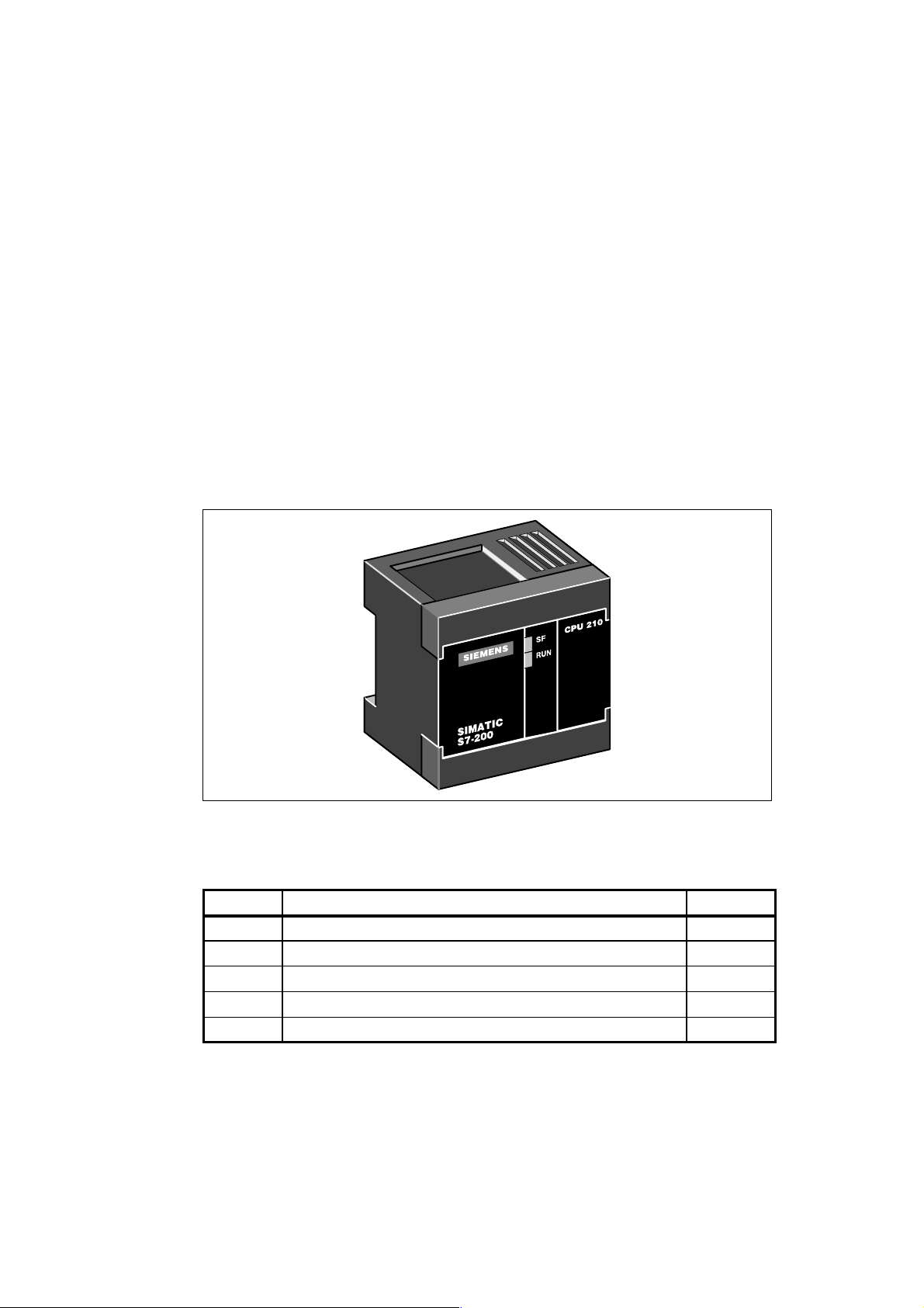
Installing the S7-200 CPU 210
The S7-200 CPU 210 is one of the S7-200 series of micro-programmable logic controllers
(Micro PLCs) that can control a variety of automation applications. Figure 1-1 shows an
S7-200 CPU 210. The compact design and low cost of the CPU 210 make a perfect solution
for controlling small applications. In addition, the variety of input and output voltages provides
you with the flexibility you need to solve your automation problems with the maintenance-free
operation of the CPU 210.
The CPU 210 is easy to install. You can use the mounting holes to attach the module to a
panel, or you can use the built-in DIN clips to mount the module onto a DIN rail. The small
size of the CPU 210 allows you to make efficient use of space.
1
Figure 1-1 S7-200 CPU 210
Chapter Overview
Section Description Page
1.1 Product Overview 1-2
1.2 Pre-installation Considerations 1-4
1.3 Installing a CPU 210 1-6
1.4 Installing the Field Wiring 1-8
1.5 Using Suppression Circuits 1-12
S7-200 Programmable Controller, CPU 210
C79000-G7076-C235-01
1-1
Page 12
Installing the S7-200 CPU 210
1.1 Product Overview
The CPU 210 combines a central processing unit (CPU), power supply, and discrete I/O
points into a compact, stand-alone device.
S The CPU executes the program and stores the data for controlling the automation task or
process.
S The inputs and outputs are the system control points: the inputs monitor the signals from
the field devices (such as sensors and switches), and the outputs control pumps, motors,
or other devices in your process.
S Status lights provide visual information about the CPU mode (RUN) or whether a system
fault (SF) has been detected.
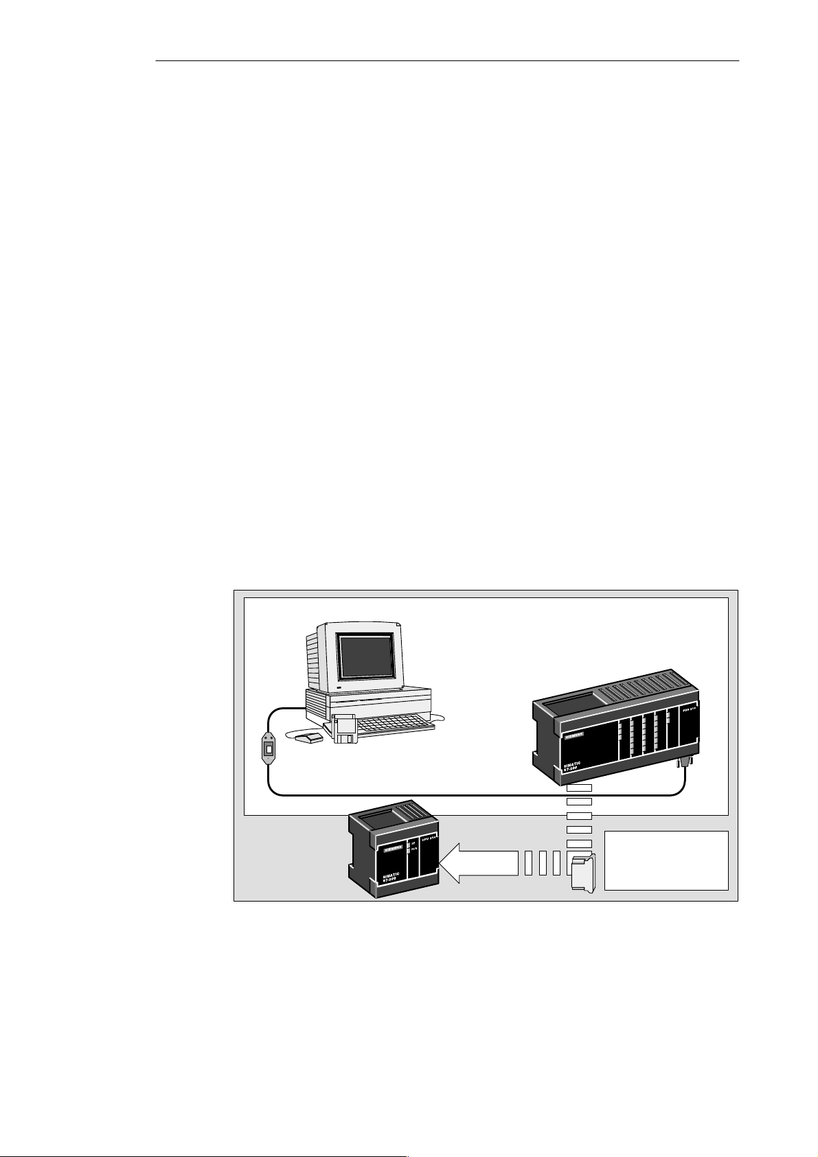
Equipment Requirements
As shown in Figure 1-2, you use the STEP 7-Micro/WIN programming software with a
program development station (the PDS 210) to create and to test your program. The final
program is then loaded onto a memory cartridge, which is then installed in the CPU 210. You
need the following equipment to create programs for the CPU 210:
S Personal computer (PC) running the STEP 7-Micro/WIN programming software. Refer to
Chapter 2 for the requirements for installing the STEP 7-Micro/WIN software.
S Program development station (PDS 210).
S PC/PPI communications cable.
S Memory cartridge for transferring the program to the CPU 210.
Refer to the data sheets in Appendix A for order numbers and other specifications of this
equipment.
Components for developing a program for the CPU 210
Computer
STEP 7-Micro/WIN
PC/PPI Communications Cable
CPU 210
Figure 1-2 Components of a CPU 210 Micro PLC System
Program Development Station
(PDS 210)
Memory cartridge
transfers the program
to the CPU 210
1-2
S7-200 Programmable Controller, CPU 210
C79000-G7076-C235-01
Page 13
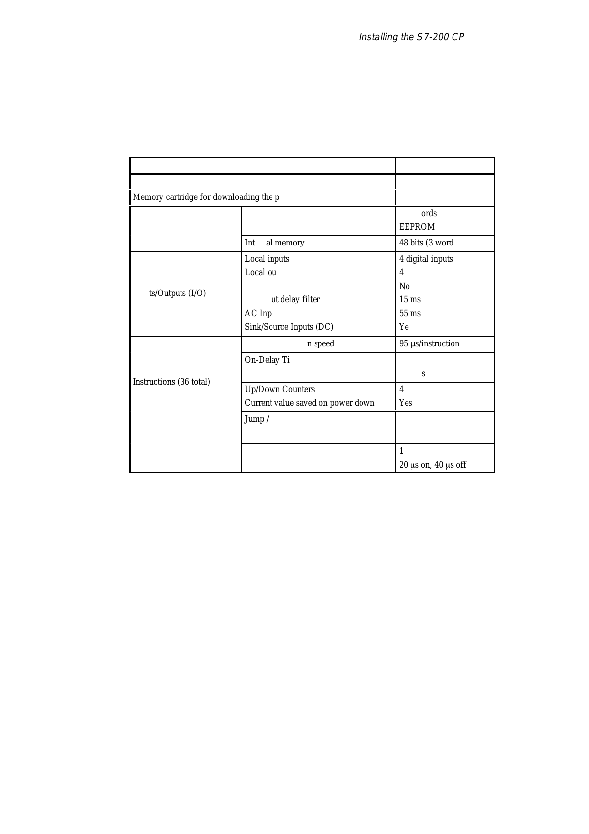
Features of the CPU 210
БББББББ
Á
Á
БББББББ
Á
y
Á
Á
Á
Á
Á
Á
Á
Á
Á
Á
Á
Á
Á
Á
Á
Á
Á
Á
Inst
(36 total)
Á
Á
Á
Á
Á
Á
Á
The CPU 210 is an integral part of the S7-200 family of Micro PLCs. Table 1-1 provides a
summary of the major features of the CPU 210.
Table 1-1 Features of the CPU 210
Installing the S7-200 CPU 210
Feature
CPU 210
Physical Size (length x width x depth) 90 x 80 x 62 mm
Memory cartridge for downloading the program
Program size
ББББББ
Memory
ББББББББББ
Storage type
Internal memory
Local inputs
ББББББ
ББББББ
Inputs/Outputs (I/O)
ББББББ
ББББББ
ББББББ
ББББББББББ
Local outputs
ББББББББББ
Expansion I/O
DC Input delay filter
ББББББББББ
AC Input delay filter
ББББББББББ
Sink/Source Inputs (DC)
ББББББББББ
Boolean execution speed
On-Delay Timers
ББББББÁББББББББББ
ructions
ББББББ
ББББББÁББББББББББ
Resolution
Up/Down Counters
Current value saved on power down
ББББББББББ
Jump / Label
Analog adjustment potentiometers
Additional Features
ББББББ
Hardware Input Interrupts
Interrupt response
ББББББББББ
Yes
256 words
ББББББ
EEPROM
48 bits (3 words)
4 digital inputs
ББББББ
4 digital outputs
ББББББ
No
15 ms
ББББББ
55 ms
ББББББ
Yes
ББББББ
95 µs/instruction
4
100 ms
ББББББ
4
Yes
ББББББ
Yes
ББББББ
1
1
20 s on, 40 s off
ББББББ
S7-200 Programmable Controller, CPU 210
C79000-G7076-C235-01
1-3
Page 14
Installing the S7-200 CPU 210
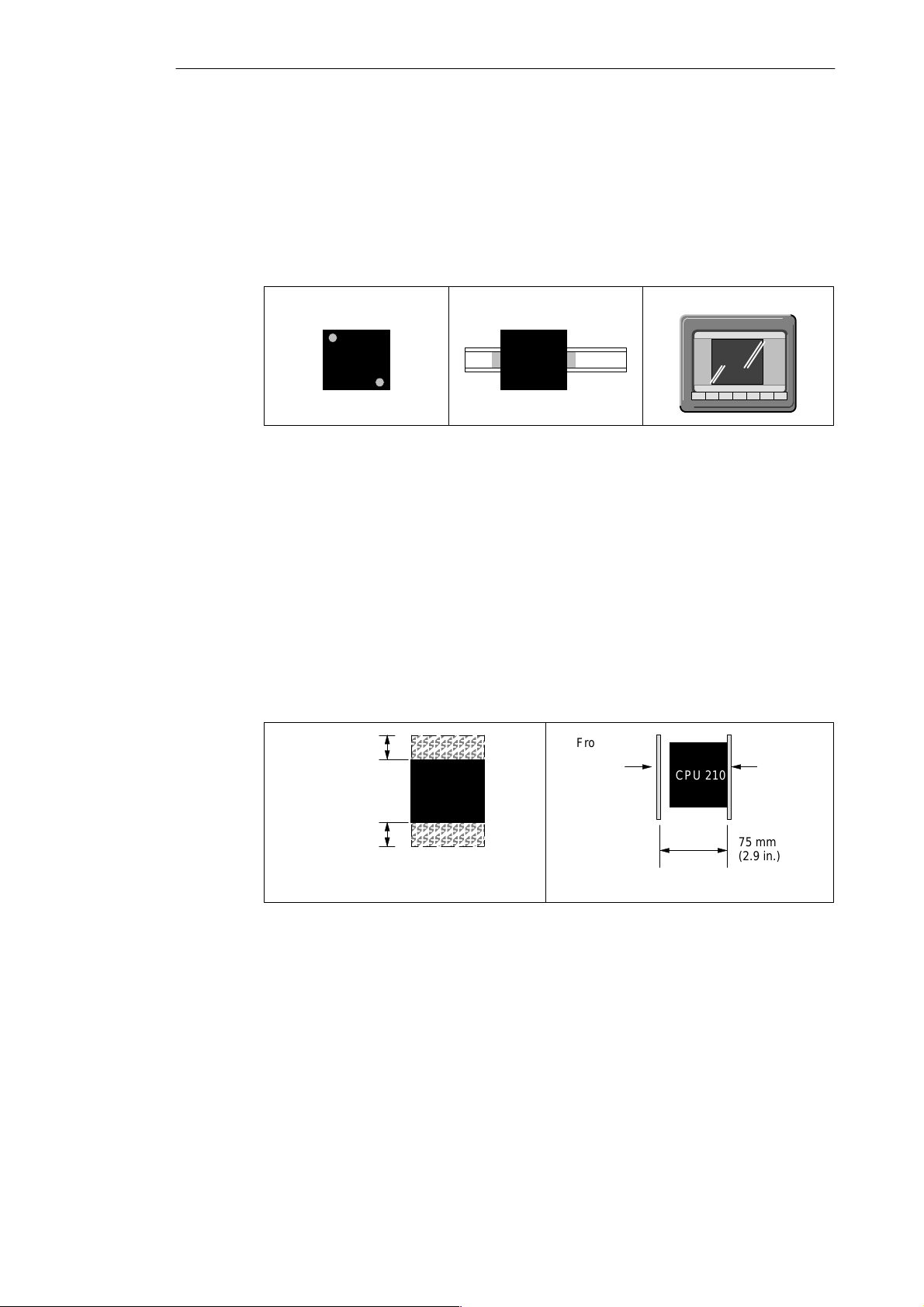
1.2 Pre-installation Considerations
Installation Configuration
As shown in Figure 1-3, you can install a CPU 210 either on a panel or on a DIN rail. You can
mount the CPU 210 either horizontally or vertically.
Mounting on a Panel Mounting on a DIN Rail
CPU 210
Figure 1-3 Mounting Configurations
Clearance Requirements for Installing a CPU 210
Use the following guidelines as you plan your installation:
S The CPU 210 is designed for natural convection cooling. You must provide a clearance
of at least 25 mm (1 inch), both above and below the units, for proper cooling. See
Figure 1-4. Continuous operation of all electronic products at maximum ambient
temperature and load will reduce their life.
S If you are installing a CPU 210 on a panel, you must allow 75 mm (2.9 inches) for the
minimum panel depth. See Figure 1-4.
S Be sure to allow enough space in your mounting design to accommodate the I/O wiring
connections.
25 mm
(1 in.)
Clearance for cooling
CPU 210
CPU 210
Front of the
enclosure
Mounting in a Panel Box
CPU 210
Mounting
surface
CPU 210
1-4
25 mm
(1 in.)
Front View Side View
Figure 1-4 Clearance Requirements for Installing a CPU 210
S7-200 Programmable Controller, CPU 210
75 mm
(2.9 in.)
C79000-G7076-C235-01
Page 15
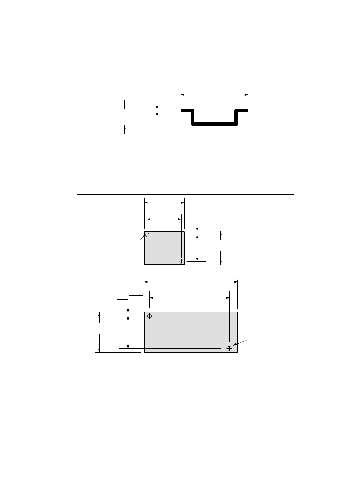
DIN Rail Requirements
The CPU 210 can be installed on a standard DIN rail (DIN EN 50 022). Figure 1-5 shows the
dimensions for this DIN rail.
Installing the S7-200 CPU 210
Figure 1-5 DIN Rail Dimensions
Panel-Mounting Dimensions
The CPU 210 and the PDS 210 include mounting holes to facilitate installation on panels.
Figure 1-6 provides the mounting dimensions.
Mounting Holes
(M4 or no. 8)
7.5 mm
(0.29 in.)
1.0 mm
(0.039 in.)
90 mm
(3.54 in.)
77.3 mm
(3.04 in.)
CPU 210
67.3 mm
(2.65 in.)
35 mm
(1.38 in.)
6.4 mm
(0.25 in.)
80 mm
(3.15 in.)
6.4 mm
(0.25 in.)
6.4 mm
(0.25 in.)
80 mm
(3.15 in.)
67.3 mm
(2.65 in.)
Figure 1-6 Mounting Dimensions for the CPU 210 and PDS 210
S7-200 Programmable Controller, CPU 210
C79000-G7076-C235-01
197 mm
(7.76 in.)
184.3 mm
(7.25 in.)
Program Development Station
(PDS 210)
Mounting Holes
(M4 or no. 8)
1-5
Page 16

Installing the S7-200 CPU 210
1.3 Installing a CPU 210
Warning
!
Mounting a CPU 210 on a Panel
Failure to disable all power to the CPU 210 and related equipment during installation or
removal procedures may result in death or serious personal injury , and/or damage to
equipment.
Disable all power to the CPU 210 and related equipment before installation or removal.
Always follow appropriate safety precautions and ensure that power to the CPU 210 is
disabled before installation.
To install a CPU 210 on a panel, follow these steps:
1. Locate, drill, and tap the mounting holes for DIN M4 or American Standard number 8
screws. Refer to Section 1.2 for mounting dimensions and other considerations.
2. Secure the CPU 210 onto the panel, using DIN M4 or American Standard number 8
screws.
Installing a CPU 210 on a DIN Rail
To install a CPU 210 on a DIN rail (as shown in Figure 1-7), follow these steps:
1. Secure the DIN rail every 75 mm (approximately 3 inches) to the mounting panel.
2. Snap open the DIN clip (located on the bottom of the CPU 210) and hook the back of the
module onto the DIN rail.
3. Snap the DIN clip closed, carefully checking to ensure that the DIN clip fastened the
module securely onto the rail.
Note
Modules in an environment with high vibration potential or modules that have been
installed in a vertical position may require DIN Rail Stops.
Figure 1-7 Installing a CPU 210 on a DIN Rail
CPU 210
Fasten DIN rail every 75 mm
(approximately 3 inches)
DIN Clip
1-6
S7-200 Programmable Controller, CPU 210
C79000-G7076-C235-01
Page 17
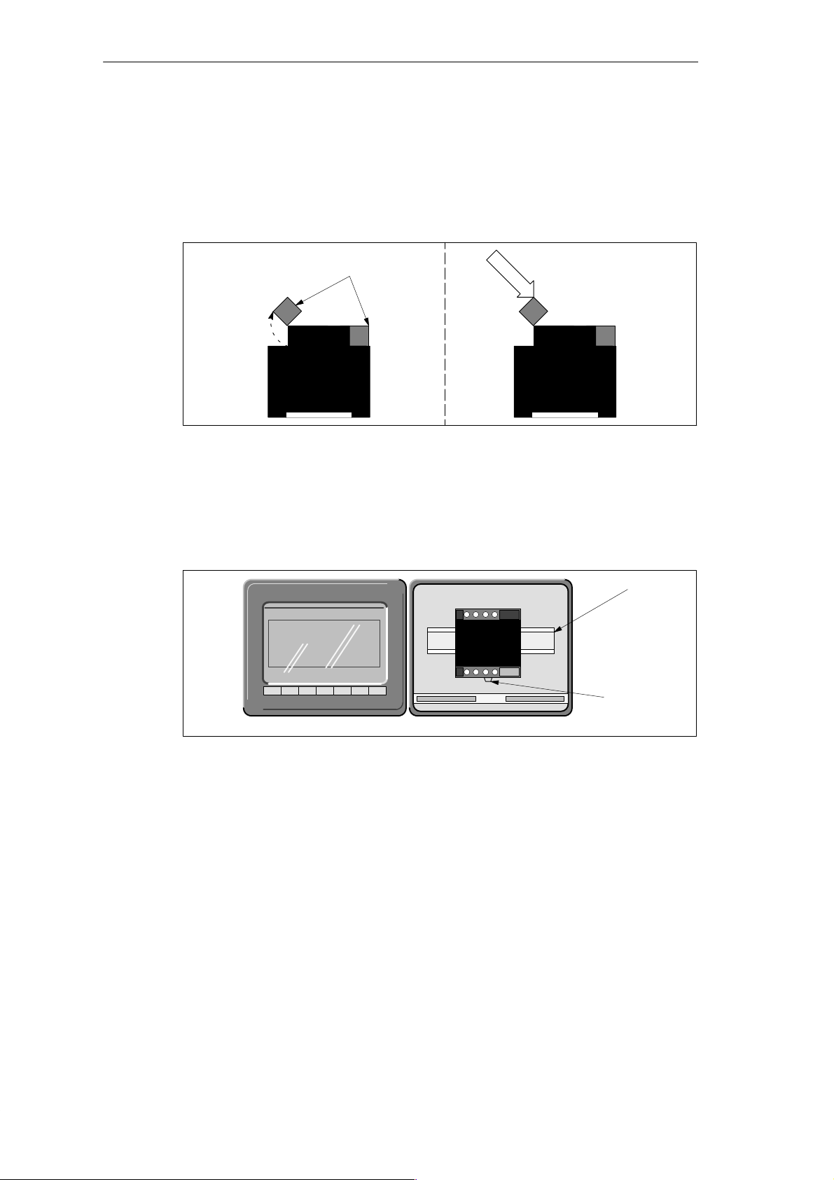
Installing a CPU 210 in a Panel Box
To install a CPU 210 in a panel box, follow these steps:
1. Open one of the I/O access covers on the CPU 210. As shown in Figure 1-8, remove the
access cover by gently pressing against the access cover until the hinges spring free.
Repeat this procedure for the other access cover.
Installing the S7-200 CPU 210
Open the access cover. Gently press against the
CPU 210
CPU 210
(Side View)
(Side View)
Access covers
access cover until the
access cover snaps off.
CPU 210
CPU 210
(Side View)
(Side View)
Figure 1-8 Removing the Access Covers from the CPU 210
2. Snap open the DIN clip (located on the bottom of the module).
3. Open the panel box and hook the back of the module onto the DIN rail. See Figure 1-9.
4. Snap the DIN clip closed, carefully checking to ensure that the DIN clip fastened the
module securely onto the rail.
DIN rail
CPU 210
Figure 1-9 Installing the CPU 210 in a Panel Box
S7-200 Programmable Controller, CPU 210
C79000-G7076-C235-01
DIN Clip
1-7
Page 18

Installing the S7-200 CPU 210
1.4 Installing the Field Wiring
Warning
!
General Guidelines
Failure to disable all power to the CPU 210 and related equipment during installation or
removal procedures may result in death or serious personal injury , and/or damage to
equipment.
Disable all power to the CPU 210 and related equipment before installing or removing field
wiring.
Always follow appropriate safety precautions and ensure that power to the CPU 210 is
disabled before installing field wiring.
The following items are general guidelines for designing the installation and wiring of your
S7-200 CPU 210:
S Ensure that you follow all applicable electrical codes when wiring the CPU 210. Install
and operate all equipment according to all applicable national and local standards.
Contact your local authorities to determine which codes and standards apply to your
specific case.
S Always use the proper wire size that will carry the required current. The CPU 210 accepts
wire sizes from 1.50 to 0.50 mm
S Ensure that you do not over-tighten the connector screws. The maximum torque is
0.56 N-m (5 inches-pounds).
S Always use the shortest wire possible (maximum 500 meters shielded, 300 meters
unshielded). Wiring should be run in pairs, with a neutral or common wire paired with a
hot or signal-carrying wire.
S Separate AC wiring and high-energy , rapidly switched DC wiring from low-energy signal
wiring.
S Properly identify and route the wiring to the CPU 210, using strain relief for the wiring as
required. For more information about identifying the terminals, see the data sheets in
Appendix A.
S Install appropriate surge suppression devices for wiring that is subject to lightning surges.
S External power should not be applied to an output load in parallel with a DC output point.
This may cause reverse current through the output, unless a diode or other barrier is
provided in the installation.
2
(14 to 22 AWG).
1-8
Warning
!
Control devices can fail in an unsafe condition, resulting in unexpected operation of
controlled equipment.
Such unexpected action could result in death or serious personal injury , and/or equipment
damage.
Consider using an emergency stop function, electromechanical overrides, or other
redundant safeguards that are independent of the programmable controller.
S7-200 Programmable Controller, CPU 210
C79000-G7076-C235-01
Page 19

Installing the S7-200 CPU 210
Grounding and Circuit Referencing Guidelines for Using Isolated Circuits
The following items are grounding and circuit guidelines for using isolated circuits:
S You should identify the reference point (0 voltage reference) for each circuit in the
installation, and the points at which circuits with possible different references can connect
together. Such connections can result in unwanted current flows that can cause logic
errors or damage circuits. A common cause of different reference potentials is grounds
which are physically separated by long distances. When devices with widely separated
grounds are connected with a sensor cable, unexpected currents can flow through the
circuit created by the cable and the ground. Even over short distances, load currents of
heavy machinery can cause differences in ground potential or directly induce unwanted
currents by electromagnetic induction. Power supplies that are improperly referenced
with respect to each other can cause damaging currents to flow between their associated
circuits.
S The CPU 210 includes isolation boundaries at certain points to help prevent unwanted
current flows in your installation. When you plan your installation, you should consider
where these isolation boundaries are, and where they are not provided. You should also
consider the isolation boundaries in associated power supplies and other equipment, and
where all associated power supplies have their reference points.
S You should choose your ground reference points and use the isolation boundaries
provided to interrupt unneeded circuit loops that could allow unwanted currents to flow.
Remember to consider temporary connections which may introduce a new circuit
reference, such as the connection of a programming device to the CPU.
S When locating grounds, you must also consider safety grounding requirements and the
proper operation of protective interrupting devices.
The following descriptions are an introduction to general isolation characteristics of the
CPU 210, but some features may be different on specific products. Consult the data sheet in
Appendix A for your product for specifications of which circuits include isolation boundaries
and the ratings of the boundaries. Isolation boundaries rated less than 1500 V AC are
designed as functional isolation only and should not be depended on as safety boundaries.
S CPU logic reference is the same as DC Sensor Supply M.
S CPU logic reference is the same as the input power supply M on a CPU with DC power
supply.
S CPU logic is isolated from ground to 100 VDC.
S DC digital inputs and outputs are isolated from CPU logic to 500 V AC.
S Relay outputs and AC inputs are isolated from CPU logic to 1500 V AC.
S Relay output groups are isolated from each other by 1500 V AC.
S AC power supply Line and Neutral are isolated from ground, the CPU logic, and all I/O to
1500 V AC.
S7-200 Programmable Controller, CPU 210
C79000-G7076-C235-01
1-9
Page 20

Installing the S7-200 CPU 210
Using the Optional Field Wiring Connector
The optional field wiring fan-out connector (Figure 1-10) allows for field wiring connections to
remain fixed when you remove and re-install the CPU 210. Refer to Appendix F for the order
number.
DC
M L+ 0.0 0.1 0.2 0.3
OUTPUTS
Figure 1-10 Optional Field Wiring Connector
Guidelines for AC Installation
The following items are general wiring guidelines for AC installations. Refer to Figure 1-1 1.
S Provide a single disconnect switch (A) that removes power from the CPU, all input
circuits, and all output (load) circuits.
S Provide overcurrent devices (B) to protect the CPU power supply, the output points, and
the input points. You can also fuse each output point individually for greater protection.
External overcurrent protection for input points is not required when you use the 24 VDC
sensor supply (C) from the CPU 210. This sensor supply is short-circuit protected.
S Connect all CPU 210 ground terminals to the closest available earth ground (D) to
provide the highest level of noise immunity . It is recommended that all ground terminals
be connected to a single electrical point. Use 14 AWG or 1.5 mm
connection.
If required, you can use a DC Sensor Supply from the CPU 210 to supply power for the
inputs (E). Refer to the guidelines for DC installation, especially in regard to connecting and
external power supply in parallel with the power supply of the CPU 210.
↓ M L+ 24V DC
Field Wiring
Fan-out Connector
2
wire for this
Guidelines for DC Installation
The following items are general wiring guidelines for isolated DC installations. Refer to
Figure 1-1 1.
S Provide a single disconnect switch (1) that removes power from the CPU, all input
circuits, and all output (load) circuits.
S Provide overcurrent devices to protect the CPU power supply (2), the output points (3),
and the input points (4). You can also fuse each output point individually for greater
protection. External overcurrent protection for input points is not required when you use
the 24 VDC sensor supply from the CPU 210. This sensor supply is internally current
limited.
S Ensure that the DC power supply has sufficient surge capacity to maintain voltage during
sudden load changes. External capacitance (5) may be required.
1-10
S7-200 Programmable Controller, CPU 210
C79000-G7076-C235-01
Page 21
Installing the S7-200 CPU 210
S Install or equip ungrounded DC power supplies with a resistor and a capacitor in parallel
(6) from the power source common to protective earth ground. The resistor provides a
leakage path to prevent static charge accumulations, and the capacitor provides a drain
for high frequency noise. Typical values are 1M Ω and 4700 pf. You can also create a
grounded DC system by connecting the DC power supply to ground (7).
S Connect all CPU 210 ground terminals to the closest available earth ground (8) to
provide the highest level of noise immunity . It is recommended that all ground terminals
be connected to a single electrical point. Use 14 AWG or 1.5 mm
connection.
2
wire for this
S Always supply 24 VDC circuits from a source that provides safe electrical separation from
120/230 VAC power and similar hazards. Refer to the following documents for standard
definitions of “safe separation”: PEL V (protected extra low voltage) according to
EN60204-1, and Class 2 or Limited Voltage/Current Circuit according to UL 508.
Warning
!
Connecting an external 24 VDC power supply in parallel with the DC sensor supply of the
CPU 210 can result in a conflict between the two supplies as each seeks to establish its
own preferred output voltage level. The result of this conflict can be shortened lifetime or
immediate failure of one or both power supplies, with consequent unpredictable operation
of the PLC system. Unpredictable operation could result in death or serious injury to
personnel, and/or damage to equipment and property .
The CPU 210 DC Sensor Supply and any external power supply should provide power to
different points, with at most one connection between the two supplies.
120/230 V AC Using a Single Overcurrent
Switch to Protect the CPU and Load Wiring
L1
N
PE
24 VDC
L1
N
PE
(A)
(E)
DO
DI
(B)
(D)
(B)
Fuse
(C)
M L+
P/S
CPU 210
AC/DC/Rly
Figure 1-11 Wiring Guidelines for AC and DC Installation
Isolated DC System Installation
(1)
(5)
Floating (6) or Grounded (7)
AC
DC
(2)
(3)
(4)
L+ M
(6)
(7)
DO
DI
(8)
P/S
CPU 210
DC/DC/DC
S7-200 Programmable Controller, CPU 210
C79000-G7076-C235-01
1-11
Page 22
Installing the S7-200 CPU 210
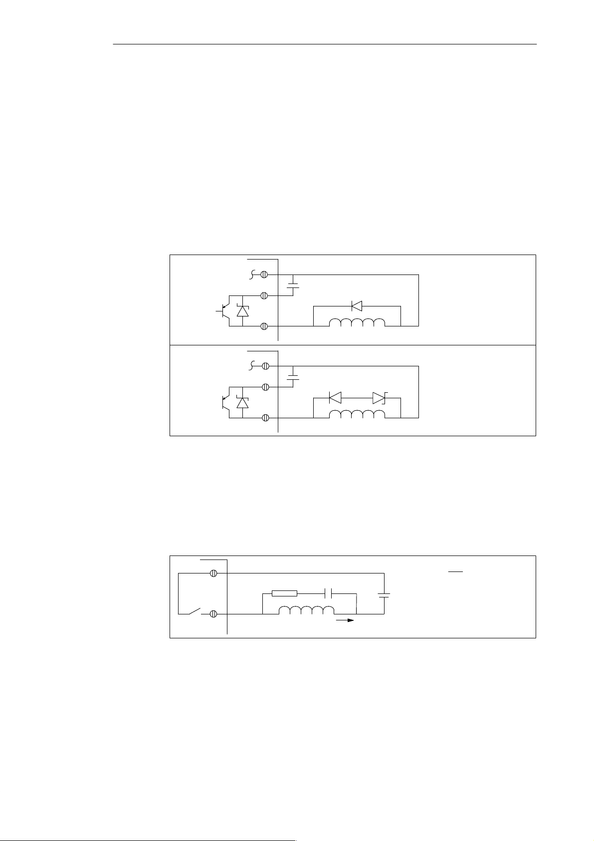
1.5 Using Suppression Circuits
Install or equip inductive loads with suppression circuits that limit voltage rise on loss of
power. Use the following guidelines to design adequate suppression. The ef fectiveness of a
given design is dependent on the application, and you must verify it for a particular use. Be
sure all components are rated for use in the application.
Protecting DC Transistors
The DC transistor outputs of the CPU 210 contain zener diodes that are adequate for many
installations. Use external suppression diodes for either large or frequently switched
inductive loads to prevent overpowering the internal diodes. Figure 1-12 shows typical
applications for DC transistor outputs.
Diode
Suppression
Zener Diode
Suppression
Figure 1-12 Diode Suppression and Zener Diode Suppression
Protecting Relays Controlling DC Power
Resistor/capacitor networks, as shown in Figure 1-13, can be used for low voltage (30 V) DC
relay applications. Connect the network across the load. You can also use diode
suppression, as shown in Figure 1-12, for DC relay applications. A threshold voltage of up to
36 V is allowed if you use a reverse zener diode.
+VDC
+VDC
RC
Inductor
(1)
Inductor
(1) (2)
Inductor
I
L
+VDC
(1) IN4001 diode or
equivalent
(1) IN4001 diode or
equivalent
(2) 8.2 V zener, 5 W
V
DC
R
I
L
where minimum R = 12Ω
K
C I
L
where K is 0.5 to 1 µ F/A
1-12
Figure 1-13 Resistor/Capacitor Network on Relay-Driven DC Load
S7-200 Programmable Controller, CPU 210
C79000-G7076-C235-01
Page 23

Installing and Using the STEP 7-Micro/WIN Version 2.0 Software
This manual describes Version 2.0 of STEP 7-Micro/WIN. Previous versions of the software
may operate differently.
STEP 7-Micro/WIN is a Windows-based software application used for programming the
S7-200 Micro PLC (programmable logic controller). The STEP 7-Micro/WIN programming
software package provides a set of tools required to program the S7-210 in either statement
list (STL) or ladder logic (LAD) programming language.
In order to use STEP 7-Micro/WIN, you must have the following equipment:
S Recommended: a personal computer (PC) with an 80486 or greater processor and
8 Mbyte of RAM or a Siemens programming device (such as a PG 740);
computer requirement: 80386 with 8 Mbyte of RAM
S A PC/PPI cable connected to your communications port (COM)
S A program development station (PDS 210)
S VGA monitor, or any monitor supported by Microsoft Windows
S At least 35 Mbyte of free hard disk space (recommended)
S Microsoft Windows 3.1, Windows for Workgroups 3.11, Windows 95, or Windows NT 3.51
or greater
S Optional but recommended: any mouse supported by Microsoft Windows
STEP 7-Micro/WIN provides extensive online help. Use the Help menu command or press
F1 to obtain the most current information.
minimum
2
Chapter Overview
Section
2.1 Installing the STEP 7-Micro/WIN Version 2.0 Software 2-2
2.2 Establishing Communication with the PDS 210 2-3
2.3 Configuring the Preferences for STEP 7-Micro/WIN 2-5
2.4 Creating and Saving a Project 2-6
2.5 Creating a Program 2-7
2.6 Downloading a Program 2-10
2.7 Using Symbolic Addressing 2-13
2.8 Using the Status Chart 2-15
2.9 Debugging and Monitoring Your Program 2-16
2.10 Error Handling for the PDS 210 2-17
S7-200 Programmable Controller, CPU 210
C79000-G7076-C235-01
Description Page
2-1
Page 24

Installing and Using the STEP 7-Micro/WIN Version 2.0 Software
2.1 Installing the STEP 7-Micro/WIN Version 2.0 Software
Pre-installation Instructions
Before running the setup procedure, do the following:
S If a previous version of STEP 7-Micro/WIN is installed, back up all application programs
to diskette.
S Make sure all applications are closed, including the Microsoft Office toolbar.
Installation may require that you restart your computer.
Installation Instructions for Windows 3.1
If you have Windows 3.1 (Windows for Workgroups 3.11 or Windows NT) on your machine,
use the following procedure to install the STEP 7-Micro/WIN software:
1. Start by inserting Disk 1 in the disk drive of your computer (usually designated drive A: or
drive B:).
"
2. From the Program Manager, select the menu command File
3. In the Run dialog box, type a:\setup and click on the “OK” button. This starts the setup
procedure.
4. Follow the online setup procedure to complete the installation.
Run...
Installation Instructions for Windows 95
If you have Windows 95 on your machine, you can use the following procedure to install the
STEP 7-Micro/WIN software:
1. Start by inserting Disk 1 in the disk drive of your computer (usually designated drive A: or
drive B:).
2. Click once on the Start button to open the Windows 95 menu.
3. Click on the Run... menu item.
4. In the Run dialog box, type a:\setup and click on the “OK” button. This starts the setup
procedure.
5. Follow the online setup procedure to complete the installation.
Troubleshooting the Installation
The following situations can cause the installation to fail:
S Not enough memory: you need to have at least 35 Mbyte of free space on your hard disk.
S Bad diskette: verify that the diskette is bad, then call your salesman or distributor.
S Operator error: start over and read the instructions carefully .
S Failure to close any open applications, including the Microsoft Office toolbar .
Note
x
Review the README
about STEP 7-Micro/WIN. (In the
C = French, D = Spanish, E = Italian.)
.TXT file included on your diskettes for the most recent information
x
position, the letter A = German, B = English,
2-2
S7-200 Programmable Controller, CPU 210
C79000-G7076-C235-01
Page 25
Installing and Using the STEP 7-Micro/WIN Version 2.0 Software
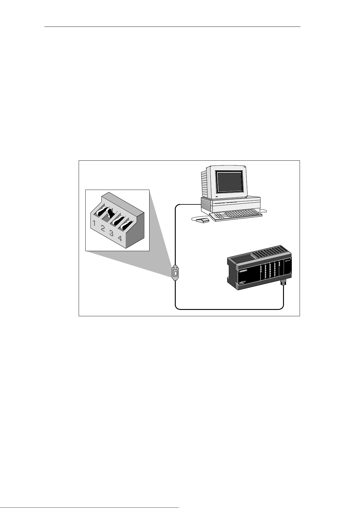
2.2 Establishing Communication with the PDS 210
Connecting Your Computer to the PDS 210 for PPI Communications
Figure 2-1 shows a typical configuration for connecting your personal computer to your
PDS 210 with the PC/PPI cable. To establish proper communications between the
components, follow these steps:
1. Set the dipswitches on the PC/PPI cable for the baud rate of 9600 baud.
2. Connect the RS-232 end of the PC/PPI cable labeled PC to the communications port of
your computer, either COM1 or COM2, and tighten the connecting screws.
3. Connect the other end (RS-485) of the PC/PPI cable to the communications port of the
PDS 210, and tighten the connecting screws.
Dipswitch Settings:
0 1 0 0 = 9600 baud
RS-232
Computer
PC/PPI cable
Figure 2-1 Communicating with a PDS 210 in PPI Mode
Program development station
(PDS 210)
RS-485
S7-200 Programmable Controller, CPU 210
C79000-G7076-C235-01
2-3
Page 26
Installing and Using the STEP 7-Micro/WIN Version 2.0 Software
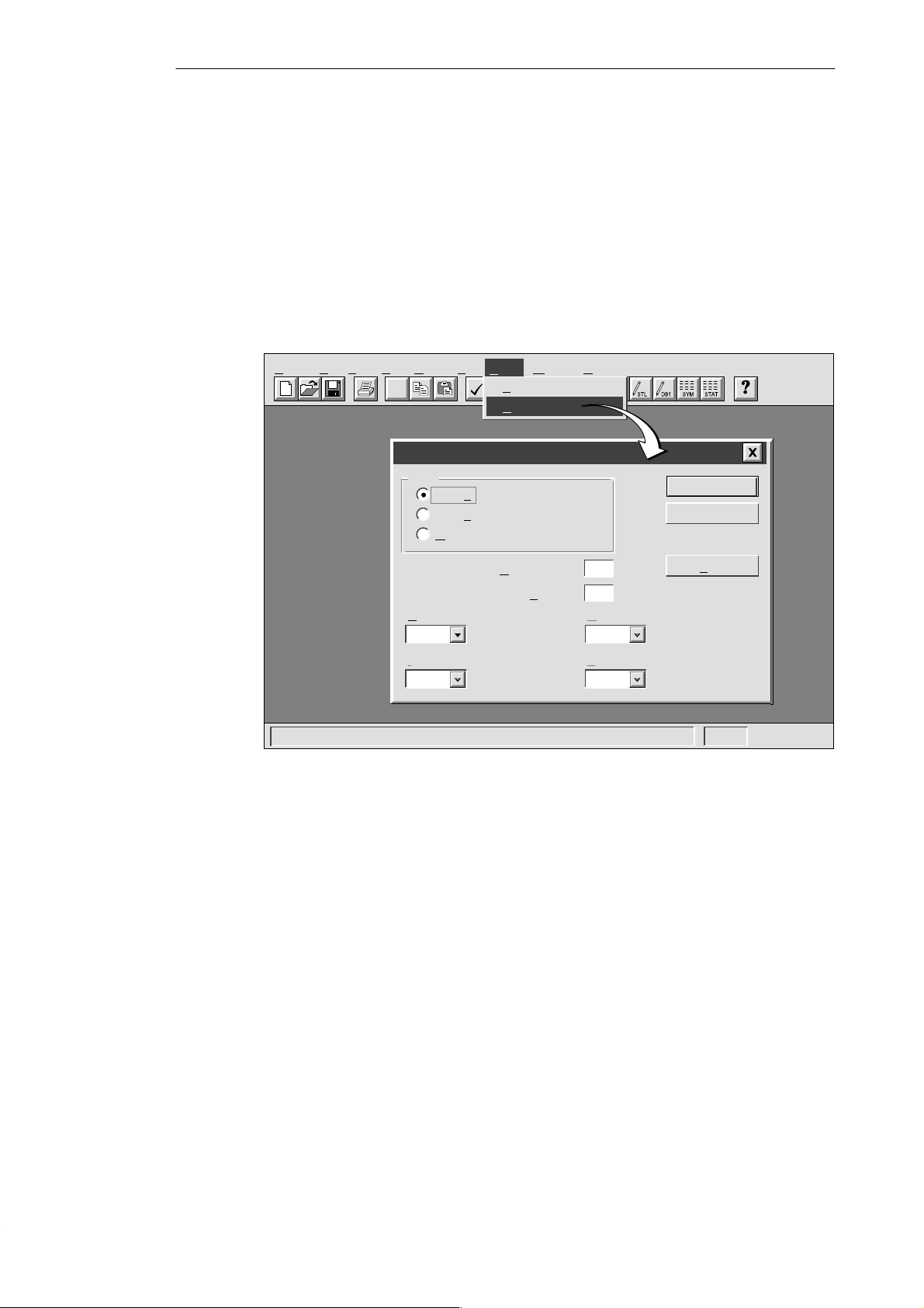
Setting Up the Communications Parameters
Figure 2-2 shows the Setup Communications dialog box. The first two port options are for PC
communication ports. The address for the PDS 210 is 2 and cannot be changed. To set up
the communication parameters, follow these steps:
1. Select the menu command Setup " Communications...
2. Verify that the information in the dialog box is correct for your configuration. Remember
that the CPU address for the PDS 210 is always 2, and that the baud rate is always
9600.
3. Confirm your selections by clicking the “OK” button.
Project Edit View CPU Debug Tools Setup Window Help
✂
Communications
Port
COM1
COM2
MPI Card
aud Rate:
B
9,600
RQ Number For MPI Card::
I
10
Setup
Preferences...
C
ommunications...
PU Address:
C
Micro/WIN A
ddress:
H
T
Figure 2-2 Setting Up Communications with the PDS 210
OK
Cancel
2
0
ighest Master Address:
31
arget Token Rotation Time::
39
Find
2-4
S7-200 Programmable Controller, CPU 210
C79000-G7076-C235-01
Page 27
Installing and Using the STEP 7-Micro/WIN Version 2.0 Software
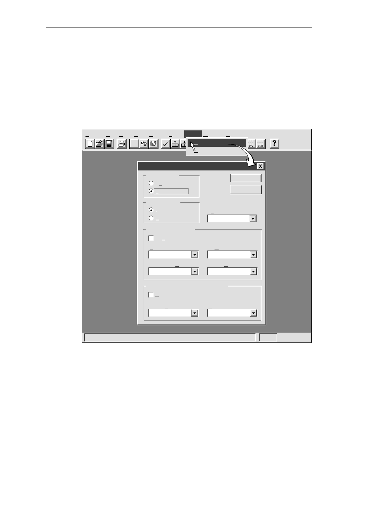
2.3 Configuring the Preferences for STEP 7-Micro/WIN
Before creating a new project, specify the preferences for your programming environment. To
select your preferences, follow these steps:
"
1. Select the menu command Setup
2. Select your programming preferences in the dialog box that appears.
3. Confirm your choices by clicking the “OK” button.
Preferences... as shown in Figure 2-3.
rmat
Setup
Preferences...
C
ommunications...
Language
English
Symbol Table
Minimized
Status Chart
Data Size
Project Edit View CPU Debug Tools Setup Window Help
✂
Preferences
Default Editor
STL Editor
L
adder Editor
Mnemonic Set
International
SIMATIC
Initial Window States
Maximize All
Program Editor
Normalized
Data Block Editor
Minimized Minimized
Options for an Uploaded Data Block
Retain Format and Comments
Data Fo
Hexadecimal Byte
OK
Cancel
Figure 2-3 Selecting Your Programming Preferences
S7-200 Programmable Controller, CPU 210
C79000-G7076-C235-01
2-5
Page 28
Installing and Using the STEP 7-Micro/WIN Version 2.0 Software
2.4 Creating and Saving a Project
Before you create a program, you must create or open a project. When you create a new
project, STEP 7-Micro/WIN opens the following editors:
S Ladder Editor or Statement List Editor (depending on your selected preference)
S Data Block Editor (not applicable for the PDS 210)
S Status Chart
S Symbol Table
Creating a New Project
The Project menu command allows you to create a new project, as shown in Figure 2-4.
Select the menu command Project
select the CPU type from the drop-down list box, the software displays only those options
which are available for your CPU. If you select “None,” no CPU-specific restrictions are
placed on your program. When you download the program, the CPU notifies you if you have
used options that are not available. For example, if your program uses an instruction that is
not supported by your CPU, the program is rejected.
"
New.... The CPU Type dialog box is displayed. If you
Note
STEP 7-Micro/WIN does not range-check parameters. For example, you can enter MW999
as a parameter to a ladder instruction even though it is an invalid parameter. This error
would be identified when you attempt to download the program.
Figure 2-4 Creating a New Project
Saving a Project
You can save a copy of the active project to a different name or location by selecting the
menu command Project " Save As... You can save all of the components of your project by
selecting the menu command Project
Project
Project View CPU Setup Help
New... Ctrl+N
O
pen... Ctrl+O
1
c:\microwin\project1.prj
2 c:\microwin\project2.prj
3
c:\microwin\project3.prj
Ex
it
✂
CPU Type
Select or read the CPU type from your PLC if you would like the software to
limit the available options to only those supported by a specific CPU.
LAD STL SYM STATDB1
PDS 210CPU Type:
OK
"
Save All or by clicking the Save button:
Read CPU Type
Communications...
Cancel
2-6
S7-200 Programmable Controller, CPU 210
C79000-G7076-C235-01
Page 29
Installing and Using the STEP 7-Micro/WIN Version 2.0 Software
2.5 Creating a Program
STEP 7-Micro/WIN allows you to create the user program (OB1) with either the Ladder Editor
or the Statement List Editor.
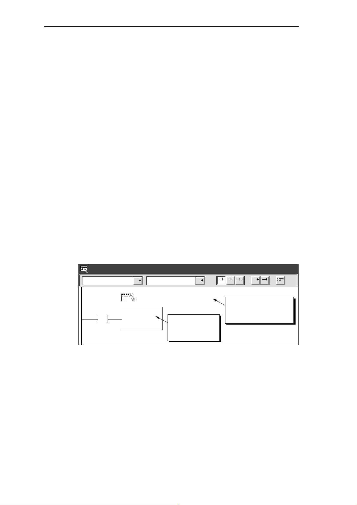
Entering Your Program in Ladder
The Ladder Editor window allows you to write a program using graphical symbols. See
Figure 2-5. The toolbar includes some of the more common ladder elements used to enter
your program. The first (left) drop-down list box contains instruction categories. You can
access these categories by clicking or pressing F2. After a category is selected, the second
drop-down list contains the instructions specific to that category . To display a list of all
instructions in alphabetic order, press F9 or select the All Instructions category.
Each network allows two types of comments:
S Single-line network title comments are always visible in the ladder display . You can
access the network editor by double-clicking anywhere in the network title region.
S Multi-line network comments are only visible through a dialog box, but can be printed (if
that option has been selected through the Page Setup dialog). You can access the
network comment editor by double-clicking anywhere in the network title region.
To start entering your program, follow these steps:
1. To enter a program title, select the menu command Edit
2. To enter ladder elements, select the type of element you want by clicking the
corresponding icon button or selecting from the instruction list.
3. Type the address or parameter in each text field and press ENTER.
To change or replace one of the elements, move the cursor to that element and select the
new element. You can also cut, copy, or paste elements at the cursor location.
"
Program Title.
Ladder Editor - project1.ob1
Contacts Normally Open
Network 1
NETWORK TITLE (single line)
I0.0
Figure 2-5 Ladder Editor Window
F3F2
Press ENTER or
double-click to
place element.
F4 F5 F8F7F6 F10
Double click here to
access the network title
and comment editor.
S7-200 Programmable Controller, CPU 210
C79000-G7076-C235-01
2-7
Page 30
Installing and Using the STEP 7-Micro/WIN Version 2.0 Software
Entering Your Program in Statement List
The Statement List (STL) Editor is a free-form text editor which allows a certain degree of
flexibility in the way you choose to enter program instructions. Figure 2-6 shows an example
of a statement list program.
You can cut, copy, and paste in the STL Editor. STEP 7-Micro/WIN also includes
search-and-replace functions.
STL
STL Editor - project1.ob1
// Program for a Home Security System
NETWORK 1 //Sound the alarm!
LD I0.3 // If (the panic alarm has been turned on)
LDW>= T0, +600 // or (if the alert timer is >= 60 seconds
A I0.2 // and the system is armed)
OLD // then
S M0.1, 1 // set the high-level alarm bit
S Q0.3, 1 // set the modem dialer bit
R M0.2, 1 // reset the low-level alarm bit
Network 2 //Evaluate the system status.
LDN I0.0 // If zone 1 is open
ON I0.1 // or if Zone 2 is open
To allow viewing the
program in STL or Ladder,
divide segments of code
with keyword NETWORK.
Figure 2-6 STL Editor Window with Sample Program
To enter an STL program, follow these guidelines:
S Start each comment with a double slash (//). Each additional comment line must also
begin with a double slash.
S End each line with a carriage return.
S Separate each instruction from its address or parameter with a space or tab.
S Do not use a space between the operand type and the address (for example, enter I0.0,
not I 0.0).
S Separate each operand within an instruction with a comma, space, or tab.
S Use quotation marks when entering symbol names. For example, if your symbol table
contains the symbol name Start1 for the address I0.0, enter the instruction as follows:
LD “Start1”
To be able to view an STL program in ladder, you must divide segments of code into
separate networks by entering the keyword NETWORK. (Network numbers are generated
automatically after you compile or upload the program.)
Compiling the Program
After completing a network or series of networks, you can check the syntax of your code by
selecting the menu command CPU
2-8
"
Compile or by clicking the Compile button:
S7-200 Programmable Controller, CPU 210
C79000-G7076-C235-01
Page 31

Installing and Using the STEP 7-Micro/WIN Version 2.0 Software
Viewing a Program in Ladder or Statement List
You can view a program in either ladder or STL by selecting the menu command View
"
or View
Ladder, as shown in Figure 2-7.
When you change the view from STL to ladder and back again to STL, you may notice
changes in the presentation of the STL program, such as:
S Instructions and addresses are changed from lower case to upper case.
S Spaces between instructions and addresses are replaced with tabs.
You can accomplish the same formatting of the STL instructions by selecting the menu
command CPU
Note
Certain combinations of statement list instructions cannot successfully be converted to
ladder view. In that case, the message “Illegal Network” marks the section of code that
cannot be represented in ladder. You can view the STL instructions for the “illegal” network
by clicking on the network title. Use the STL Editor to modify an illegal network so that it
can be viewed in ladder.
"
Compile while the STL Editor is active.
"
STL
STEP 7-Micro/WIN - c:\microwin\project1.prj
Project Edit View CPU Debug Tools Setup Window Help
Ladder Editor - untitled.ob1
Contacts
Network 1
“Start1” “E-Stop1” Q0.0
View
STL
✂
L
adder
D
ata Block
Symbol T
Status C
Cross R
Element U
✓
Sy
✓
Toolb
Sta
✓
Z
able
F2
Normally Open
hart
eference
Start/stop switch
sage
mbolic Addressing Ctrl+Y
ar
tus Bar
oom...
F3
STL
NETWORK 1 //Start/stop switch
LD “Start1”
AN “E-Stop1”
= Q0.0
NETWORK 2 //End
MEND
F4 F5 F8F7F6
STL Editor - untitled.ob1
Figure 2-7 Changing the Program View from Ladder to Statement List
F10
S7-200 Programmable Controller, CPU 210
C79000-G7076-C235-01
2-9
Page 32

Installing and Using the STEP 7-Micro/WIN Version 2.0 Software
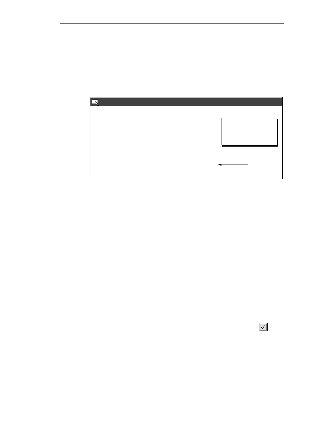
2.6 Downloading A Program
After developing and testing your program on the PDS 210, you must transfer the program to
the CPU 210 using the memory cartridge. In the same manner as you could use a diskette to
transfer files from one computer to another, you use a memory cartridge to transfer your
program from the PDS 210 to the CPU 210.
Downloading the Program to the PDS 210
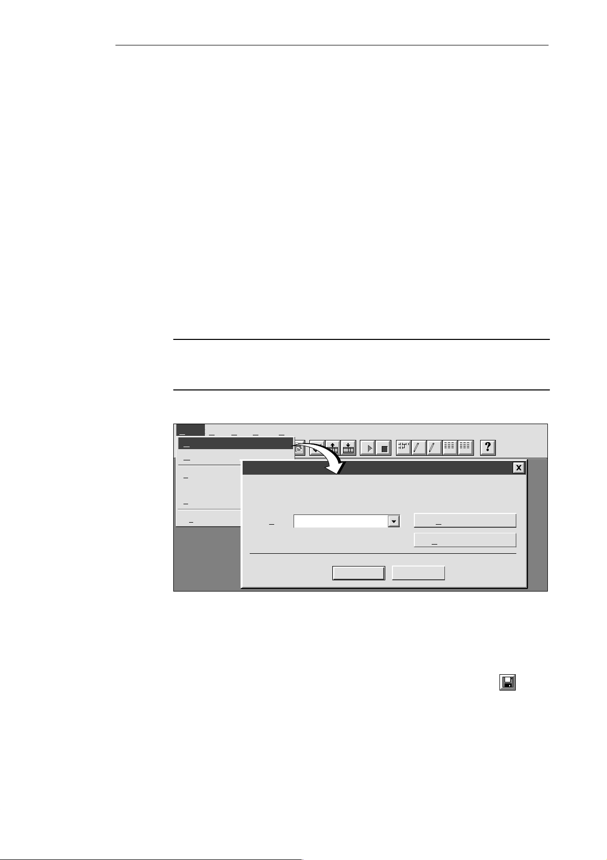
After completing your program, you can download the project to the PDS 210. To download
your program, select the menu command Project
button in the main window.
The Download dialog box that appears allows you to specify the project components you
want to download, as shown in Figure 2-8. Select only “Program Code Block” for the
PDS 210: the data block and the CPU configuration are not used by the CPU 210.
Click on the “OK” button to confirm your choices and to execute the download operation.
STEP 7-Micro/WIN - c:\microwin\project1.prj
Project
Project Edit View CPU Debug Tools Setup Window Help
New... Ctrl+N
O
pen... Ctrl+O
C
lose
✂
"
Download... or click the Download
S
ave All Ctrl+S
Save A
s...
I
mport
E
xport
U
pload... Ctrl+U
D
ownload... Ctrl+D
Pag
e Setup...
P
rint Preview...
P
rint... Ctrl+P
Pr
int Setup...
Ex
it
Download
ll
A
Program Code Block
D
ata Block
Configuration
CPU
Figure 2-8 Downloading Project Components to the CPU
OK
Cancel
2-10
S7-200 Programmable Controller, CPU 210
C79000-G7076-C235-01
Page 33

Installing and Using the STEP 7-Micro/WIN Version 2.0 Software
Copying Your Program to the Memory Cartridge
You can copy your program to the memory cartridge only when the PDS 210 is powered up
and the memory cartridge is installed. (You can install or remove the memory cartridge while
the PDS 210 is powered up.)
Caution
!
Electrostatic discharge can damage the memory cartridge or the receptacle on the
PDS 210 or CPU 210.
You should make contact with a grounded conductive pad and/or wear a grounded wrist
strap when you handle the cartridge. You should store the cartridge in a conductive
container.
To install the memory cartridge, remove the protective tape from the memory cartridge
receptacle and insert the memory cartridge into the receptacle located under an access
cover of the PDS 210. (The memory cartridge is keyed for proper installation.) After the
memory cartridge is installed, use the following procedure to copy the program:
1. If the program has not already been downloaded to the PDS 210, use the menu
"
command Project
2. Use the menu command CPU
Download... to download the program. (See Figure 2-8.)
"
memory cartridge. See Figure 2-9.
3. Remove the memory cartridge from the PDS 210.
Program Memory Cartridge to copy the program to the
STEP 7-Micro/WIN - c:\microwin\project1.prj
Project Edit View CPU Debug Tools Setup Window Help
Ladder Editor - untitled.ob1
Contacts
Network 1
“Zone_1” “Zone_2” Q0.0
CPU
Run
✂
S
top
C
ompile
F2
Normally Open
Cl
ear
I
nformation
Start/stop switch
Co
nfigure
Program Memory Cartridge
✓
Time of Day Clock
Compare Project to CPU
T
ype
Figure 2-9 Copying the Program to the Memory Cartridge
Transferring the Program to the CPU 210
To transfer the program from the memory cartridge to the CPU 210, follow these steps:
1. Turn off the power to the CPU 210.
2. Insert the memory cartridge in the CPU 210. (The memory cartridge is keyed for proper
installation.)
3. Turn on the power to the CPU 210.
4. After the RUN LED turns on, remove the memory cartridge from the CPU 210.
S7-200 Programmable Controller, CPU 210
C79000-G7076-C235-01
2-11
Page 34

Installing and Using the STEP 7-Micro/WIN Version 2.0 Software
As shown in Figure 2-10, the CPU 210 performs the following tasks after you turn the power
on when a memory cartridge is installed in the CPU 210:
S The M, T, and Q areas of memory are cleared.
S The current values for the counters (which are stored in the permanent memory) are
cleared. (The current values for the counters are erased only when the memory cartridge
is installed in the CPU 210. If a memory cartridge is not installed, the current values are
retained.)
S The user program is copied from the memory cartridge to the permanent EEPROM
memory .
Always remove the memory cartridge from the CPU 210 after the program has been
installed.
Note
Turning the power on with a blank memory cartridge in the CPU 210 causes an error and
lights the error LED. Any program stored in the permanent EEPROM is not affected or
overwritten. To correct the error condition, remove the memory cartridge and cycle the
power again.
When a valid program is installed, the CPU 210 automatically goes to RUN mode when
power is applied.
As your program runs, the CPU 210 updates the values stored in the RAM memory (the
values stored in M memory , the current values for the four counters, and the current values
for the four timers).
When you turn the power off, the CPU 210 saves the current values of the four counters to
the permanent EEPROM memory . The other values stored in RAM (such as M memory,
current values for the timers, and the copy of the user program) are cleared.
Unless a memory cartridge is installed in the CPU 210, the current values for the counters
are retentive. The current values for the counters are automatically restored to the RAM
memory when you turn power on for the CPU 210 (with no memory cartridge installed).
When the memory cartridge is installed in the CPU 210,
Memory
Cartridge
User Program
Current values
of the counters
EEPROM Memory (Permanent)
turning on the power copies the user program to the
permanent memory
RAM Memory
M memory
Counter values
Current values
of the counters
Current values
of the timers
2-12
Figure 2-10 Loading a Program with the Memory Cartridge
S7-200 Programmable Controller, CPU 210
C79000-G7076-C235-01
Page 35

Installing and Using the STEP 7-Micro/WIN Version 2.0 Software
2.7 Using Symbolic Addressing
The Symbol Table allows you to give symbolic names to inputs, outputs, and internal
memory locations. See Figure 2-1 1. You can use the symbols you have assigned to these
addresses in the Ladder Editor, STL Editor, and Status Chart of STEP 7-Micro/WIN.
Guidelines for Entering Symbolic Addresses
The first column of the Symbol Table is used to select a row. The other columns are for the
symbol name, address, and comment. For each row, you assign a symbolic name to the
absolute address of a discrete input, output, memory location, special memory bit, or other
element. A comment for each assigned symbol is optional. Follow these guidelines when
creating a Symbol Table:
S You can enter symbol names and absolute addresses in any order.
S You can use up to 23 characters in the Symbol Name field; however, depending on the
font size of your Windows environment, you may not see the full name displayed in the
Ladder Editor.
S You can define up to 500 symbols.
S The Symbol Table is case-sensitive: for example, “Low_Alert” is considered a different
symbol from “low_alert”.
S All leading and trailing spaces will be removed from the symbol name. All adjacent
internal spaces will be converted to a single underscore. For example, if you type
“Zone 1” and press ENTER, the symbol name appears as: “Zone_1”.
S Duplicate symbol names and/or addresses will be marked by blue italics, will not be
compiled, and cannot be used in the program. Overlapping addresses are not flagged as
duplicates; for example, MW0 and MW1 overlap in memory but are not flagged as
duplicates.
Starting the Symbol T able Editor
The Symbol Table editor appears by default as a minimized window icon at the bottom of the
main window. To access the Symbol Table, double-click the icon, or click the Restore or
Maximize button on the icon (in Windows 95).
Symbol Table - untitled.sym
Symbol Name Address Comment
Zone_1
Zone_2
Armed
Panic_Alarm
LED
Alarm
Low_Alert
LED_Bit
LED_Bit
Figure 2-11 Example of a Symbol Table
To clear a cell, press
I0.0
delete key or spacebar
I0.1
when cell is selected.
I0.2
I0.3
Q0.0
Q0.1
Duplicate symbols
Q0.2
are displayed in
M0.0
italics.
M0.1
Zone 1 (switches A to F)
Zone 2 (switches H to M)
Enables the security system
Turns on the siren
S7-200 Programmable Controller, CPU 210
C79000-G7076-C235-01
2-13
Page 36

Installing and Using the STEP 7-Micro/WIN Version 2.0 Software
Editing Functions within the Symbol T able
The Symbol Table provides the following editing functions:
S Edit
S Edit
S Edit
"
Cut / Copy / Paste within a cell or from one cell to another.
"
Cut / Copy / Paste one or several adjacent rows.
"
Insert Row(s) above the row containing the cursor. You can also use the INSERT
or INS key for this function.
S Edit
"
Delete Row(s) for one or several highlighted adjacent rows. You can also use the
DELETE or DEL key for this function.
S To edit any cell containing data, use the arrow keys or mouse to select the cell you want
to edit. If you begin typing, the field clears and the new characters are entered. If you
double-click the mouse or press F2, the field becomes highlighted, and you can use the
arrow keys to move the editing cursor to the place you want to edit.
S Clicking the right mouse button displays a menu of editing functions which are available
with the Symbol Table editor.
Sorting Table Entries
After entering symbol names and their associated absolute addresses, you can sort the
Symbol Table alphabetically by symbol names or numerically by addresses in the following
ways:
S Select the menu command View
alphabetical order.
S Select the menu command View
numerically in the following order for memory types: I, Q, M, C, T, and SM.
"
Sort Symbol Name to sort the symbol names in
"
Sort Symbol Address to sort the absolute addresses
Displaying the Symbolic Addresses
After you create the Symbol Table for your program, you can use the menu command View
Symbolic Addressing to enable or disable the use of symbolic addressing with the Program
Editor (ladder or STL) and the Status Chart. See Figure 2-12.
STEP 7-Micro/WIN - c:\microwin\project1.prj
Project Edit View CPU Debug Tools Setup Window Help
Ladder Editor - untitled.ob1
Contacts
Network 1
“Start1” “E-Stop1” Q0.0
View
S
TL
L
adder
D
ata Block
F2
Symbol T
Status C
Start/stop switch
Cross R
Element U
✓
Sy
mbolic Addressing
✓
Toolb
Sta
tus Bar
✓
Z
oom...
Figure 2-12 Displaying the Symbolic Addresses
✂
Normally Open
able
hart
eference
sage
ar
"
2-14
S7-200 Programmable Controller, CPU 210
C79000-G7076-C235-01
Page 37

Installing and Using the STEP 7-Micro/WIN Version 2.0 Software
2.8 Using the Status Chart
The Status Chart editor appears by default as a minimized window icon at the bottom of the
main window. To access the Status Chart, double-click the icon, or click the Restore or
Maximize button on the icon (in Windows 95).
You can use the Status Chart to read or write variables in your program. You cannot force
values in the PDS 210.
Reading and Writing Variables with the Status Chart
Figure 2-13 shows an example of a Status Chart. To read or write variables using the Status
Chart, follow these steps:
1. In the first cell in the Address column, enter the address or the symbol name of an
element from your program that you want to read or write, and press ENTER. Repeat this
step for all additional elements you want in the chart.
2. If the element is a bit (I, Q, or M, for example), the format is set as bit in the Format
column. If the element is a word, select the cell in the Format column and double-click or
press the SPACEBAR to cycle through the valid formats.
3. To view the current PLC value of the elements in your chart, click the Single Read
button
or the Continuous Read button on the Status Chart.
You can click the Stop Read button
4. To change a value, enter the new value in the Change Value to column and click the
Write button
Figure 2-13 Example of a Status Chart
Editing Addresses
To edit an address cell, use the arrow keys or mouse to select the cell you want to edit.
S If you begin typing, the field clears and the new characters are entered.
S If you double-click the mouse or press F2, the field becomes highlighted and you can use
the arrow keys to move the editing cursor to the place you want to edit.
S Clicking the right mouse button displays a menu of editing functions which are available
with the Status Chart editor.
to write the value to the PDS 210.
Status Chart
Address Format
I0.0 Bit 2#0
I0.1 Bit 2#0
Q0.1 Bit 2#1
Q0.2 Bit 2#0
T0
MW0 Integer 4400
Integer
Current PLC Value
+84
to stop the updating of status.
Change Value to
1
To change a value,
enter new value here
and click the Write
button.
Press the spacebar or
double-click in the cell
to select valid format.
S7-200 Programmable Controller, CPU 210
C79000-G7076-C235-01
2-15
Page 38

Installing and Using the STEP 7-Micro/WIN Version 2.0 Software
2.9 Debugging and Monitoring Your Program
Using Single/Multiple Scans to Monitor Y our Program
You can specify that the PDS 210 execute your program for a limited number of scans (from
1 scan to 65,535 scans). By selecting the number of scans for the PDS 210 to run, you can
monitor the program as it changes the process variables. Use the menu command
Debug
shows the dialog box for entering the number of scans for the CPU to execute.
"
Execute Scans... to specify the number of scans to be executed. Figure 2-14
Execute Scan
1Execute program scan(s)
Figure 2-14 Executing Your Program for a Specific Number of Scans
Displaying the Status of the Program in Ladder Logic
As shown in Figure 2-15, the program editor of STEP 7-Micro/WIN allows you to monitor the
status of the online program. (The program must be displaying ladder logic.) This allows you
to monitor the status of the instructions in the program as they are executed by the CPU.
STEP 7-Micro/WIN - c:\microwin\house.prj
Project Edit View CPU Debug Tools Setup Window Help
Debug
Execute Scans...
✂
Ladder Status O
Contacts Normally Open
Network 1
I0.3
T0
>=I
+600
I0.2
Sound the alarm!
M0.1
S
1
Q0.3
S
1
M0.2
R
OK
Cancel
n
F3F2
F4 F5 F8F7F6 F10
2-16
Figure 2-15 Displaying the Status of a Program in Ladder Logic
S7-200 Programmable Controller, CPU 210
C79000-G7076-C235-01
Page 39

Installing and Using the STEP 7-Micro/WIN Version 2.0 Software
2.10 Error Handling for the PDS 210
The PDS 210 classifies errors as either fatal errors or non-fatal errors. You can use
STEP 7-Micro/WIN to view the error codes that were generated by the error. Figure 2-16
shows the dialog box that displays the error code and the description of the error. Refer to
Appendix C for a complete listing of the error codes.
CPU Information
General Information
Module Errors
Module 0:
Module 1:
Module 2:
Module 3:
CPU Errors
NON-Fatal:083
NON-Fatal: 11
Figure 2-16 CPU Information Dialog: Error Status Tab
Responding to Fatal Errors
Fatal errors cause the PDS 210 to stop the execution of your program. Depending upon the
severity of the fatal error, it can render the PDS 210 incapable of performing any or all
functions. The objective for handling fatal errors is to bring the PDS 210 to a safe state from
which the PDS 210 can respond to interrogations about the existing error conditions. When a
fatal error is detected by the PDS 210, the PDS 210 changes to the STOP mode, turns on
the System Fault LED and the STOP LED, and turns off the outputs. The PDS 210 remains
in this condition until the fatal error condition is corrected.
Once you have made the changes to correct the fatal error condition, you must restart the
PDS 210. You can restart the PDS 210 by cycling power. Restarting the PDS 210 clears the
fatal error condition and performs power-up diagnostic testing to verify that the fatal error has
been corrected. If another fatal error condition is found, the PDS 210 again sets the fault LED
indicating that an error still exists. Otherwise, the PDS 210 begins normal operation.
There are several possible error conditions that can render the PDS 210 incapable of
communication. In these cases, you cannot view the error code from the PDS 210. These
errors indicate hardware failures that require the PDS 210 module to be repaired; these
conditions cannot be fixed by changes to the program or clearing the PDS 210 memory .
Fatal:
Error Status Module Configuration
Not present
Not present
Not present
Not present
No fatal errors present.
Missing main end statement.
Module 4:
Module 5:
Module 6:
DP Status
Not present
Not present
Not present
Use the description and the code
for troubleshooting the possible
cause of the error.
Close
S7-200 Programmable Controller, CPU 210
C79000-G7076-C235-01
2-17
Page 40

Installing and Using the STEP 7-Micro/WIN Version 2.0 Software
Responding to Non-Fatal Errors
Non-fatal errors can degrade some aspect of the PDS 210 performance, but they do not
render the PDS 210 incapable of executing your program or from updating the I/O. As shown
in Figure 2-16, you can use STEP 7-Micro/WIN to view the error codes that were generated
by the non-fatal error. For the PDS 210, there are two basic categories of non-fatal errors:
S Run-time errors. All non-fatal errors detected in RUN mode are reflected in special
memory (SM) bits. Your program can monitor and evaluate these bits. Refer to
Appendix B for more information about the SM bits used for reporting non-fatal run-time
errors.
S Program-compile errors. The PDS 210 compiles the program as it downloads. If the
PDS 210 detects that the program violates a compilation rule, the download is aborted
and an error code is generated. (A program that was already downloaded to the PDS 210
would still exist in the EEPROM and would not be lost.) After you correct your program,
you can download it again.
The PDS 210 does not change to STOP mode when it detects a non-fatal error .
2-18
S7-200 Programmable Controller, CPU 210
C79000-G7076-C235-01
Page 41

Getting Started with a Sample Program
You can enter the program for the sample application on a computer running
STEP 7-Micro/WIN. To download the program, you must have the equipment shown in
Figure 3-1. The size of the sample program is 155 bytes.
3
Figure 3-1 Requirements to Run the Sample Program
Chapter Overview
Section
Computer
STEP 7-Micro/WIN
PC/PPI Communications Cable
Input Simulator for the PDS 210
Description Page
3.1 Defining the Requirements for the Application Example 3-2
3.2 Designing the Control Logic 3-4
3.3 Putting the Control Logic into a Program 3-9
3.4 Creating a Project with STEP 7-Micro/WIN 3-13
3.5 Creating a Symbol Table 3-14
3.6 Creating the Program 3-15
3.7 Creating a Status Chart 3-22
3.8 Downloading and Monitoring the Sample Program 3-23
3.9 Modifying the Sample Program 3-25
Program Development Station
(PDS 210)
S7-200 Programmable Controller, CPU 210
C79000-G7076-C235-01
3-1
Page 42

Inputs
p
Memory
Timers
Getting Started with a Sample Program
3.1 Defining the Requirements for the Application Example
Defining the Inputs and Outputs for the Application
This chapter describes a sample program for a home security system. As shown in
Figure 3-2, the program monitors two zones. Any breach of security results in an alarm being
sounded. The sample program uses the following inputs:
S Input 1 (I0.0) monitors zone 1 (entrance, living room, kitchen, and bedroom 3).
S Input 2 (I0.1) monitors zone 2 (bedroom 1, bedroom 2, bathroom, and rear entrance).
S Input 3 (I0.2) provides the arm/disarm switch for the security system.
S Input 4 (I0.3) provides a “panic button” to immediately turn on the alarm siren.
In addition to the inputs, the program uses the following outputs.
S Output 1 (Q0.0) controls the LED on the security system.
S Output 2 (Q0.1) turns on the siren to sound an alarm.
S Output 3 (Q0.2) turns on a low-level notification alert to signify that the alarm will be
turned on in a predetermined number of seconds.
S Output 4 (Q0.3) turns on an external interface relay (perhaps to an automatic dialing
machine).
Figure 3-3 shows a wiring diagram for the home security application.
Creating Symbolic Names for the Elements of the Program
Symbolic names help to document or define the specific memory locations or I/O used by
your program. Table 3-1 lists the symbolic names used by the program for the sample
application. The sample program also uses SM0.5 to generate an on/off (blinking) pattern for
the LED.
Table 3-1 Symbolic Names for the Application Example
Element Address Symbolic Name Description
I0.0 Zone_1 Normally Closed input for Zone 1
I0.1 Zone_2 Normally Closed input for Zone 2
I0.2 Armed Armed = closed, and disarmed = open
I0.3 Panic_Alarm Normally Open input for panic alarm
Outputs
Internal
Memory
Q0.0 LED System LED (on if armed, or flashing if disarmed and
Q0.1 Alarm High-level alarm (siren)
Q0.2 Low_Alert Low-level alert to disarm system
Q0.3 Modem Relay to start the modem dialer unit
M0.0 LED_Bit Stores the status for the LED
M0.1 Alarm_Bit Stores the status for the alarm
M0.2 Low_Bit Stores the status for the low-level alert
T0 Alert_Timer Provides a delay before the alarm turns on
T2 Exit_Timer Delay time after arming the system
zone 1 or zone 2 open)
3-2
S7-200 Programmable Controller, CPU 210
C79000-G7076-C235-01
Page 43

Getting Started with a Sample Program
FI
E
Bedroom 3
D
C
Front
Entrance
Kitchen
H
Rear
Entrance
Living Room
Bedroom 2
Bath
M
Zone 1 Zone 2
BA
Figure 3-2 Sample Application for a Home Security System
Zone 1
Inputs Outputs
I0.0
DEF
ABC
1L
Q0.0
System LED
J
Bedroom 1
K
L
Zone 2
KLM
Figure 3-3 Wiring Diagram for the Sample Home Security Application
S7-200 Programmable Controller, CPU 210
C79000-G7076-C235-01
Arm/Disarm System
“Panic” Alarm
I0.1
HIJ
Q0.1
I0.2
Q0.2
I0.3
1M
Q0.3
High-level Alarm
2L
Low-level Alert
Modem Dialer
Relay
3-3
Page 44

Getting Started with a Sample Program
3.2 Designing the Control Logic
Creating a program is more involved than just entering the instructions into a file. Individual
elements or tasks make up the control logic contained within the program. These elements
relate to the various instructions, which are then arranged into networks.
This section provides an insight into how the sample program was structured.
Defining the Operation of the Program
Before entering the instructions into a program, you must plan the tasks that the program is
to perform. For the home security system described in Section 3.1, the program must
evaluate the status of the four inputs and respond by turning on or off the four outputs. As
shown in Figure 3-4, the control logic of the program must perform the following tasks:
S If the system is not armed, the program flashes the LED (Q0.0) on and off when either
Zone 1 (I0.0) or Zone 2 (I0.1) is open.
S When the system is armed (by turning the key to the “on” or “arm” position, which turns
on I0.2), the program must start a delay timer which allows 90 seconds for the owner to
exit the house. During this delay time, the program does not respond when either zone
(I0.0 or I0.1) opens.
S If the system has been armed and the delay time for exiting the house has been
achieved, the program evaluates the status of both zones. If either zone (I0.0 or I0.1)
opens, the program starts a notification sequence that turns on the low-level alert buzzer
(Q0.2) and starts a timer. This allows a reminder (and time) for the owner to disarm the
system after returning home.
S Once the notification sequence has started, the program has two possible actions:
– If the system is disarmed (by turning the key to the “off” or “disarm” position, which
turns off I0.2), the program turns off the outputs (Q0.0 and Q0.2) and resets the
timers.
– If the system has not been disarmed within 60 seconds, the program turns on the
alarm and the modem dialer (Q0.1 and Q0.3).
S If the panic alarm (I0.3) is turned on, the program turns on the alarm and the modem
dialer (Q0.1 and Q0.3). The program performs this task regardless of the state of the
arm/disarm switch (I0.2) and does not perform the notification sequence that provides a
delay time for disarming the system.
S If the system is disarmed (by turning the key to the “off” or “disarm” position, which turns
off I0.2) after the alarm (Q0.1) has been turned on, the program turns off the outputs
(Q0.1 and Q0.3) and resets the timers.
Each of these tasks can be expressed as a sequence of instructions: the conditions of the
logic determine the action to be taken.
Because the CPU 210 provides immediate outputs, the program uses the internal memory
bits (M memory) to store the interim states of the logic relating to the physical outputs. After
evaluating the control logic, the program uses the states of these memory bits to turn the
outputs on or off.
3-4
S7-200 Programmable Controller, CPU 210
C79000-G7076-C235-01
Page 45

Getting Started with a Sample Program
Zone 1 Zone 2 Armed Panic Alarm
When armed turns on,
start the exit timer and
turn on the LED.
If not armed and either
Zone 1 or Zone 2 is open,
flash the LED on and off.
On and
Off
If disarmed, then turn off the outputs
and stop the alert timer.
Turn on the alarm and start
the modem dialer.
On
On
If the system is armed and the exit timer is >= 90 seconds,
and if either Zone 1 or Zone 2 is open, then start the alert
timer and turn on the low-level alert notification.
On
If not disarmed and the alert timer is >=
60 seconds, then sound the alarm, start the
modem dialer, and turn of f the low-level alert.
Off
Figure 3-4 Basic Tasks for the Home Security Application Program
S7-200 Programmable Controller, CPU 210
C79000-G7076-C235-01
Off
On
3-5
Page 46
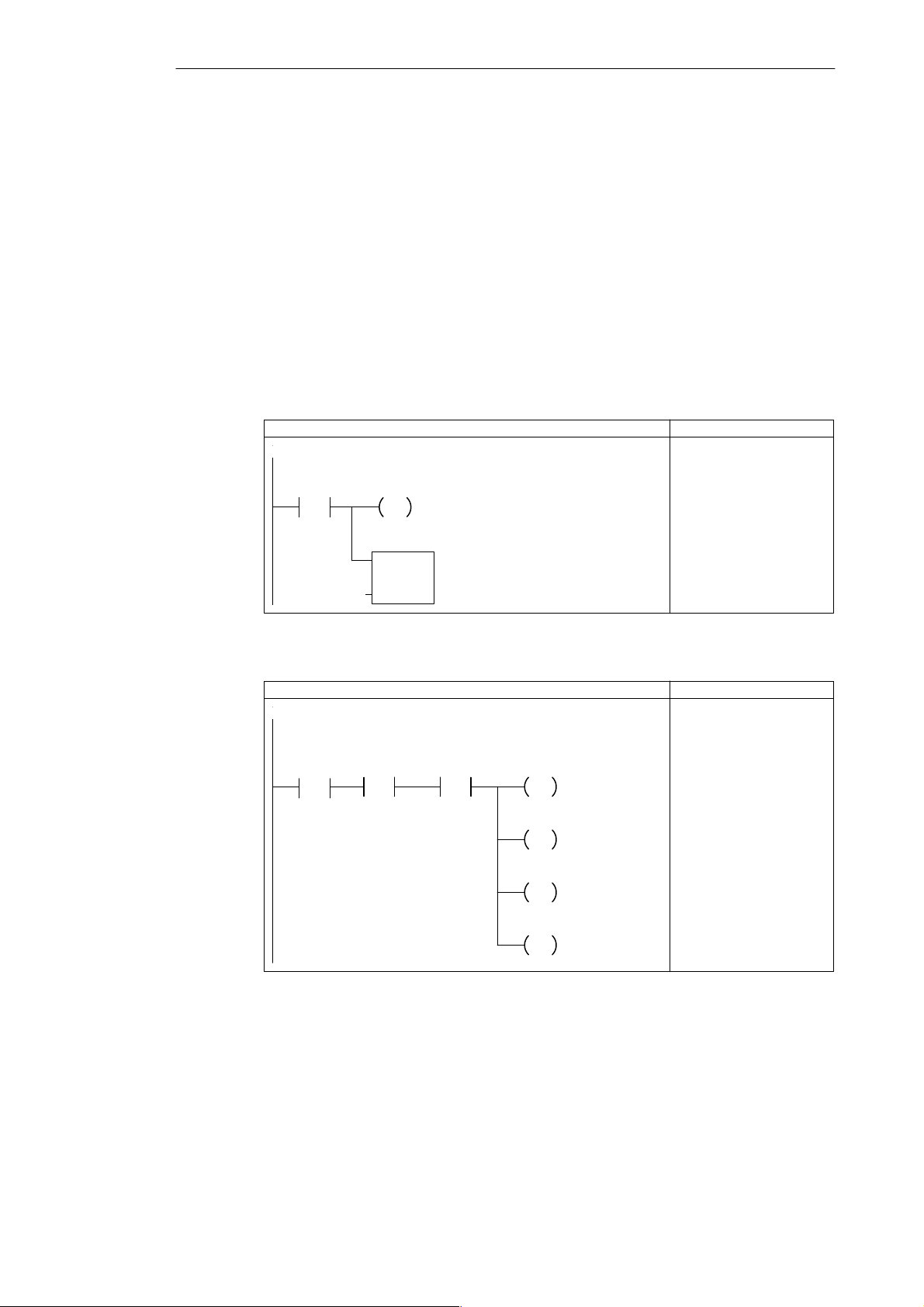
Getting Started with a Sample Program
Designing the Control Logic for Arming and Disarming the System
Figures 3-5 and 3-6 shows the control logic for arming and disarming the security system.
S As shown in Figure 3-5, arming the security system activates (enables) the bits of
M memory that control the outputs (alarm siren and modem dialer). The control logic for
arming the system also provides a delay between the turning on of the arm/disarm switch
and the activation of the security system. This allows time for the owner to arm the
system and exit the house. (There is a different timer that controls a low-level alert
notification that allows the owner to disarm the system.)
S As shown in Figure 3-6, disarming the security system stops the notification and alarm
sequence.
Before the security system has been armed, the LED flashes on and off if one of the zones is
open. Figure 3-7 shows the control logic for using one of the SM bits (SM0.5) to generate the
on/off pulse for the LED.
LAD STL
Network
If the system is armed, then set the lamp bit and start the
exit timer.
Armed
LED_Bit
S
1
Exit_Timer
TON
IN
NETWORK
LD I0.2
S M0.0, 1
TON T2, +0
PT
+0
Figure 3-5 Control Logic for Arming the Security System
LAD STL
Network
If the system is not armed, and the panic alarm is not on,
then reset the lamp bit, the alarm bit, the low-level alert bit,
and the modem bit.
Armed
/
P
Panic_Alarm
/
LED_Bit
R
1
Alarm_Bit
R
1
Low_Bit
R
1
Modem
R
1
Figure 3-6 Control Logic for Disarming the Security System
NETWORK
LDN I0.2
EU
AN I0.3
R M0.0, 1
R M0.1, 1
R M0.2, 1
R Q0.3, 1
3-6
S7-200 Programmable Controller, CPU 210
C79000-G7076-C235-01
Page 47

Getting Started with a Sample Program
LAD STL
Network
Network
Figure 3-7 Control Logic for Flashing the LED On and Off
Designing the Control Logic for Turning On the Low-Level Alert Notification
On a breach of security (created when either Zone 1 or Zone 2 opens after the security
system has been armed), the program turns on the low-level alert notification. This allows the
owner a specified time to disarm the system (such as when when re-entering the house). As
shown in Figure 3-8, the program monitors the states of both zones and the arm/disarm
switch. It also allows for the exit time (90 seconds).
After a breach of security has been identified, the program starts the timer for the low-level
alert notification.
Use the negative transition of SM0.5 to turn the LED on.
Armed
/
Zone_1
/
Zone_2
SM0.5
N
/
Use the positive transition of SM0.5 to turn the LED off.
Armed
/
Zone_1
/
Zone_2
SM0.5
P
/
LED_Bit
S
1
LED_Bit
R
1
NETWORK
LDN I0.2
LDN I0.0
ON I0.1
ALD
A SM0.5
ED
S M0.0, 1
NETWORK
LDN I0.2
LDN I0.0
ON I0.1
ALD
A SM0.5
EU
R M0.0, 1
LAD STL
Network
Zone_1
Zone_2
If the system is armed and the alarm is not already on, then
turn on the low-level alert bit when either Zone 1 or Zone 2
opens.
Armed
/
Alarm_bit
/
Exit_Timer
>=I
+900
Low_Bit
NETWORK
LDN I0.0
ON I0.1
A I0.2
AN M0.1
LDW>= T2, +900
= M0.2
/
Network
Low_Bit
If the low-level alarm bit is set (on), then start the Alert
timer.
Alert_Timer
TON
IN
PT
+0
NETWORK
LD M0.2
TON T0, +0
Figure 3-8 Control Logic for Turning On the Low-Level Alert Notification
S7-200 Programmable Controller, CPU 210
C79000-G7076-C235-01
3-7
Page 48

Getting Started with a Sample Program
Designing the Control Logic for Turning On the Alarm and Modem Dialer
Because the outputs turn on immediately , the program uses memory bits (M) for storing the
results of the control logic. See Figure 3-9. At the end of the program, these bits turn on (or
off) the outputs.
LAD STL
Network
If the LED bit is on, turn on the output for the system
LED.
LED_Bit
LED
NETWORK
LD M0.0
= Q0.0
Network
Network
If the Alarm bit is on, turn on the output for the alarm.
Alarm_Bit
If the low-level alert bit is on, turn on the output for the
low level alert.
Low_Bit
Alarm
Low_Alert
NETWORK
LD M0.1
= Q0.1
NETWORK
LD M0.2
= Q0.2
Figure 3-9 Control Logic for Turning On the Outputs
As shown in Figure 3-10, the memory bits for the alarm siren and the modem dialer are
turned on by either of two conditions:
S Someone pushes the “panic button” (regardless of the arm/disarm state of the system
and without providing the low-level alert notification).
S The system has not been disarmed during the 60 seconds that the low-level alert
notification has been on.
Turning on the alarm also resets the low-level alert notification.
LAD STL
Network
Panic_Alarm
Alert_Timer
>=I
+600
Armed
Alarm_Bit
S
1
Modem
S
1
Low_Bit
R
1
NETWORK
LD I0.3
LDW>= T0, +600
A I0.2
OLD
S M0.1, 1
S Q0.3, 1
R M0.2, 1
3-8
Figure 3-10 Control Logic for Enabling the Alarm and Modem Bits
S7-200 Programmable Controller, CPU 210
C79000-G7076-C235-01
Page 49

Getting Started with a Sample Program
3.3 Putting the Control Logic into a Program
After you have designed the control logic for your application, you arrange the instructions
into a program. You can choose either STL or ladder for your program.
Figure 3-1 1 provides a listing of the ladder program for the sample program. This program
includes the control logic from Section 3.2. The program ends with the End instruction.
Network 1
I0.3
T0
>=I
+600
Network 2
I0.0
/
I0.1
/
Network 3
M0.2
I0.2
+0
I0.2
IN
PT
Sound the alarm!
M0.1
S
1
Q0.3
S
1
M0.2
R
1
Evaluate the system status.
M0.1
/
+900
Start the Alert timer.
T0
TON
T2
>=I
M0.2
S
1
Network 4
I0.2
IN
PT
+0
Figure 3-11 Home Security Program Example in Ladder
S7-200 Programmable Controller, CPU 210
C79000-G7076-C235-01
If the system is armed, then set the lamp bit and start the exit timer.
M0.0
S
1
T2
TON
(Continued)
3-9
Page 50

Getting Started with a Sample Program
Network 5
I0.2
/
Network 6
I0.2
/
Network 7
I0.2
/
Reset everything if the system is disarmed.
I0.3
P
/
Use the negative transition to turn the LED on.
I0.0
/
I0.1
M0.0
R
1
M0.1
R
1
M0.2
R
1
Q0.3
R
1
SM0.5
M0.0
N
R
1
/
Use the positive transition to turn the LED off.
I0.0
/
I0.1
SM0.5
M0.0
P
S
1
/
Network 8
M0.0
Network 9
M0.1
Network 10
M0.2
Network 11
END
Turn on the system LED.
Q0.0
Turn on the alarm siren.
Q0.1
Turn on the low-level alert notification.
Q0.2
End of the Program.
Figure 3-11 Home Security Program Example in Ladder, continued
3-10
S7-200 Programmable Controller, CPU 210
C79000-G7076-C235-01
Page 51

Getting Started with a Sample Program
Table 3-2 provides a listing of the STL program for the sample program. This program
includes the control logic from Section 3.2. The program ends with the End instruction
(MEND).
Table 3-2 Sample Program in Statement List
STL Description
NETWORK 1
LD I0.3
LDW>= T0, +600
A I0.2
OLD
S M0.1, 1
S Q0.3, 1
R M0.2, 1
NETWORK 2
LDN I0.0
ON I0.1
A I0.2
AN M0.1
AW>= T2, +900
S M0.2, 1
NETWORK 3
LD M0.2
TON T0, +0
NETWORK 4
LD I0.2
S M0.0, 1
TON T2, +0
NETWORK 5
LDN I0.2
EU
AN I0.3
R M0.0, 1
R M0.1, 1
R M0.2, 1
R Q0.3, 1
NETWORK 6
LDN I0.2
LDN I0.0
ON I0.1
ALD
A SM0.5
ED
R M0.0, 1
NETWORK 7
LDN I0.2
LDN I0.0
ON I0.1
ALD
A SM0.5
EU
S M0.0, 1
NETWORK 8
LD M0.0
= Q0.0
// if (the panic alarm has been turned on)
// or (if the alert timer is >= 60 seconds
// and the system is armed)
// then
// set High Level Alarm bit
// set Modem Dialer bit
// reset Low Level Alarm bit
// if zone 1 is open
// or if zone 2 is open
// and the system is armed
// and the high-level alarm bit is not set
// and the exit timer is less than 90 seconds
// then set the low-level alert bit
// if the low-level alert bit has been set,
// then start the alert timer
// when the system is armed
// set the LED bit
// and start the exit timer
// if the system is not armed
// and the panic alarm is not on
// then
// reset LED bit
// reset High Level Alarm bit
// reset Low Level Alarm bit
// reset Modem Dialer
// if the system is not armed
// and if zone 1 is open
// or zone 2 is open
// and
// using the 1/2 second counter SM bit
// on the negative edge
// reset the LED bit
// if the system is not armed
// and if zone 1 is open
// or zone 2 is open
// and
// using the 1/2 second counter SM bit
// on the positive edge
// set the LED bit
// if the LED bit has been set
// turn on the LED output
S7-200 Programmable Controller, CPU 210
C79000-G7076-C235-01
3-11
Page 52

Getting Started with a Sample Program
Table 3-2 Sample Program in Statement List, continued
NETWORK 9
LD M0.1
= Q0.1
NETWORK 10
LD M0.2
= Q0.2
NETWORK 11
MEND
// if the high-level alarm bit has been set
// turn on the high-level alarm output
// if the low-level alert bit has been set
// turn on the low-level alert output
// end of the main program
3-12
S7-200 Programmable Controller, CPU 210
C79000-G7076-C235-01
Page 53

Getting Started with a Sample Program
3.4 Creating a Project with STEP 7-Micro/WIN
To create a new project, select the menu command Project " New..., as shown in
Figure 3-12. The CPU Type dialog box is displayed. Select “PDS 210” from the drop-down
list box.
You can name your project at any time; for this example, refer to Figure 3-13 and follow
these steps to name the project:
"
1. Select the menu command Project
2. In the File Name field, type the following: house.prj
3. Click on the “OK” button.
Project
Project View CPU Setup Help
New... Ctrl+N
O
pen... Ctrl+O
1
c:\microwin\project1.prj
2 c:\microwin\project2.prj
3
c:\microwin\project3.prj
Ex
it
✂
CPU Type
Select or read the CPU type from your PLC if you would like the software to
limit the available options to only those supported by a specific CPU.
PDS 210CPU Type:
Save As...
LAD STL SYM STATDB1
Read CPU Type
OK
Cancel
Figure 3-12 Creating a New Project and Selecting the CPU Type
Project Edit View CPU Debug Tools Setup Window HelpProject
New... Ctrl+N
O
pen... Ctrl+O
C
lose
S
ave All Ctrl+S
Save A
s...
I
mport
E
xport
U
pload... Ctrl+U
D
ownload... Ctrl+D
✂
Save As Project
File n
ame:
*.prj
olders:
F
c:\microwin
sample.prj c:\
Enter project
name here.
microwin
backup
Pag
e Setup...
P
rint Preview...
P
rint... Ctrl+P
Pr
int Setup...
Ex
it
Save file as type:
Project
samples
Drives:
c:
Communications...
OK
Cancel
Help
Network...
Figure 3-13 Naming the Sample Project
S7-200 Programmable Controller, CPU 210
C79000-G7076-C235-01
3-13
Page 54
Getting Started with a Sample Program
3.5 Creating a Symbol Table
To make programming easier, you can define symbolic names (or symbols) for memory
addresses. You use the Symbol Table to define the set of symbols used to represent the
absolute addresses in the sample program. To open the Symbol Table editor, double-click
the icon, or click the restore or maximize button on the icon (in Windows 95). You can also
select the menu command View
Entering the Symbol Names
Figure 3-14 shows the list of symbol names and the corresponding addresses for the sample
program. To enter the symbol names, follow these steps:
1. Select the first cell in the Symbol Name column, and type the following: Zone_1
2. Press ENTER to move the focus to the first cell in the Address column. Type the address
I0.0 and press ENTER. The focus moves to the cell in the Comment column.
(Comments are optional, but they are a useful way to document the elements in your
program.)
3. Press ENTER to start the next symbol row, and repeat these steps for each of the
remaining symbol names and addresses.
4. Use the menu command Project
"
Symbol Table...
"
Save All to save your Symbol Table.
Symbol Table - c:\microwin\house.sym
Symbol Name Address Comment
Zone_1
Zone_2
Armed
Panic_Alarm
LED
Alarm
Low_Alert
Modem Q0.3
LED_Bit M0.0
Alarm_Bit M0.1
Low_Bit M0.2
Alert_Timer T0
Exit_Timer T2 Time for exiting the house
I0.0
I0.1
I0.2
I0.3
Q0.0
Q0.1
Q0.2
Zone 1 (switches A to F)
Zone 2 (switches H to M)
Enables the security system
Turns on the siren via the panic button
Blinks to identify an open zone
Sounds an alarm
For disarming the system before siren
Enables external device (auto-dialer)
Stores the status for the LED
Stores the status for the alarm
Stores the status for the alert
Delays the alarm (allow disarm)
Figure 3-14 Symbol Table for the Sample Program
3-14
S7-200 Programmable Controller, CPU 210
C79000-G7076-C235-01
Page 55

3.6 Entering the Program
You can enter the program in either statement list (STL) or ladder. You can also use either
absolute addressing or symbolic addressing.
To enter the program in STL, you open the STL Editor window and start typing the
instructions. (You use the View
STL.) Remember to put double slashes (//) before any comments and to end each line by
pressing ENTER.
To enter the program in STL, type the commands (with or without the comments) listed in
Table 3-2. You can cut, copy, and paste in the STL Editor. STEP 7-Micro/WIN also includes
search-and-replace functions.
Programming with Symbolic Addresses
Before you start entering your program, make sure the ladder view is set for symbolic
addressing. Use the menu command View
mark next to the menu item, which indicates that symbolic addressing is enabled.
Note
Symbol names are case-sensitive. The name you enter must match exactly the uppercase
and lowercase characters entered in the symbol table. If there is any mismatch, the cursor
stays on the element and displays the “Add Symbol” dialog. You can then add the new
symbol to the Symbol Table, or cancel and correct the entry.
Getting Started with a Sample Program
"
STL menu command to change the editor from ladder to
"
Symbolic Addressing and look for a check
Using the Ladder Editor to Enter the Program
To access the Ladder Editor, double-click the icon at the bottom of the main window. (You
"
use the View
Ladder menu command to change the editor from STL to ladder.)
Figure 3-15 shows some of the basic tools you will use in the Ladder Editor.
Refer to Figure 3-1 1 for the program listing in ladder. Entering the comments is optional.
Ladder Editor - c:\microwin\house.ob1
Contacts Normally Open
NETWORK TITLE (single line)Network 1
Family
listing
Ladder Editor cursor
Instruction
listing
Figure 3-15 Some of the Basic Ladder Editor Tools
Normally open
contact button
Normally closed
contact button
F3F2
F4 F5 F8F7F6 F10
Output coil button
Vertical and
horizontal line
buttons
S7-200 Programmable Controller, CPU 210
C79000-G7076-C235-01
3-15
Page 56

Getting Started with a Sample Program
Refer to Figure 3-16 and follow these steps to enter the first network of the sample program:
1. Click the mouse cursor in the left-most position below the network title. Enter a normally
open contact by clicking the F4 toolbar button or by selecting “Contacts” from the family
listing and then selecting “Normally Open” from the instruction listing. A normally open
contact appears with the name “Zone_1” highlighted above it. (Every time you enter a
contact, the software displays the default address of I0.0, which in this example is
defined as “Zone_1” in the Symbol Table.)
2. “Panic_Alarm” is the first element required for Network 1. While “Zone_1” is highlighted,
type either the symbol name Panic_Alarm or the absolute address I0.3 (the software
accepts entry of either form).
3. Press ENTER to confirm the first element. The symbol name “Panic_Alarm” is displayed.
The ladder cursor moves to the second column position.
4. Click the F8 toolbar button to insert a horizontal line. (You can also select “Lines” from the
family listing and then select “Horizontal” from the instruction listing.)
To change or replace one of the elements, move the cursor to that element and select the
new element. You can also cut, copy, or paste elements at the cursor location.
Contacts Normally Open
Network 1
Contacts Normally Open
Network 1
Sound the alarm!
Sound the alarm!
Enter the address:
“Zone_1”
I0.3
or
Panic_Alarm
Contacts Normally Open
Network 1
“Panic_Alarm”
Sound the alarm!
F3F2
F4 F5 F8F7F6 F10
Click the toolbar
button to place
element.
F3F2
F4 F5 F8F7F6 F10
F3F2
F4 F5 F8F7F6 F10
Click the toolbar button
to insert a horizontal line
segment.
3-16
Figure 3-16 Entering the First Contact of the First Network
S7-200 Programmable Controller, CPU 210
C79000-G7076-C235-01
Page 57

Getting Started with a Sample Program
Refer to Figure 3-17 and follow these steps to enter the output coil that ends the first rung of
the first network:
1. Select “Output Coils” from the family listing and select “Set” from the instruction listing.
2. Type either the symbolic name Alarm_Bit or the absolute address M0.1 in the
highlighted area.
3. Pressing ENTER highlights the “number of points” field (located underneath the output
coil). Press ENTER to accept the default value of 1. (The CPU 210 allows only one point
to be set or reset by any one Set or Reset instruction.)
4. Move the cursor to the position below the first contact.
Output Coils Set
Network 1
“Panic_Alarm”
Select “Output Coils”
Sound the alarm!
from the family listing.
Output Coils Set
Network 1
“Panic_Alarm”
Output Coils Set
Network 1
Sound the alarm!
Sound the alarm!
Output
Set
Reset
Q0.0
F3F2
F4 F5 F8F7F6 F10
Select “Set” from the
instruction listing.
F3F2
F4 F5 F8F7F6 F10
Enter the address:
M0.1
or
Alarm_Bit
S
1
F3F2
F4 F5 F8F7F6 F10
“Panic_Alarm”
Figure 3-17 Entering the Output Coil
S7-200 Programmable Controller, CPU 210
C79000-G7076-C235-01
“Alarm_Bit”
S
1
Position the cursor
below the first contact.
3-17
Page 58

Getting Started with a Sample Program
Refer to Figure 3-18 and follow these steps to enter the two contacts on the second rung of
the first network:
1. Select “Contacts” from the family listing and select “>= Integer” from the instruction listing.
This inserts a comparison instruction at the cursor position. This instruction compares the
value of the notification timer (Alert_Timer) with the time value.
2. Type either the symbolic name Alert_Timer or the absolute address T0 in the
highlighted area. Pressing ENTER highlights the second value for the comparison.
3. Type 600 and press ENTER. This instruction becomes true (and turns on) when the timer
is greater than or equal to 600, which equals 60 seconds.
4. Click the F4 toolbar button to create a normally open contact. Type Armed (or I0.2) and
press ENTER.
Contacts >= Integer
Normally Open
Network 1
“Panic_Alarm”
Select “Contacts” from
the family listing.
Contacts >= Integer
Normally Closed
Sound the alarm!
== Integer
>= Integer
<= Integer
Not
Positive Transition
Negative Transition
Enter the address:
Network 1
Sound the alarm!
T0
or
“Panic_Alarm”
VW0
>=I
VW0
Alert_Timer
F3F2
Select “>= Integer” from the
instruction listing.
F3F2
Press ENTER and then
“Alarm_Bit”
enter the time value:
600
F4 F5 F8F7F6 F10
F4 F5 F8F7F6 F10
S
1
3-18
Contacts Normally Open
Network 1
“Panic_Alarm”
“Alert_Timer”
>=I
+600
Sound the alarm!
“Alarm_Bit”
“Armed”
S
1
F3F2
Figure 3-18 Entering the Comparison Instruction and Next Contact
S7-200 Programmable Controller, CPU 210
F4 F5 F8F7F6 F10
Insert a normally open
contact and enter I0.2
or
Armed).
(
C79000-G7076-C235-01
Page 59

Getting Started with a Sample Program
Refer to Figure 3-19 and follow these steps to enter a vertical line and to copy the output coil
from the first rung:
1. Move the cursor to the horizontal line above the contact for “Armed” (or I0.2). Click the
F7 toolbar button to insert a vertical line that connects the first rung with the second rung.
2. Move the cursor to the output coil on the first rung. Use the menu command Edit " Copy
to copy the output coil to the clipboard.
"
3. Move the cursor down and use the menu command Edit
coil. Type Modem (or Q0.3) in the highlighted field and press ENTER. Press ENTER
again to accept the default value of 1.
Paste to paste the output
Lines Vertical
Network 1
“Panic_Alarm”
“Alert_Timer”
>=I
+600
Output Coils Set
Network 1
“Panic_Alarm”
“Alert_Timer”
>=I
+600
Sound the alarm!
“Armed”
Sound the alarm!
“Armed”
Position the cursor on
the top rung of the
“Alarm_Bit”
network.
S
1
“Alarm_Bit”
S
1
F3F2
F4 F5 F8F7F6 F10
Click the toolbar button
to insert a vertical line.
F3F2
F4 F5 F8F7F6 F10
Copy the Set instruction
by selecting the
Copy command from
the Edit menu.
Output Coils Set
Network 1
“Panic_Alarm”
“Alert_Timer”
>=I
+600
Figure 3-19 Entering a Vertical Line and Copying the Output Coil
S7-200 Programmable Controller, CPU 210
C79000-G7076-C235-01
Sound the alarm!
“Armed”
“Alarm_Bit”
S
1
“Modem”
S
1
F3F2
F4 F5 F8F7F6 F10
Move the cursor vertically and
paste the instruction at the
cursor location. Use the
Paste command from the Edit
menu.
Enter the address (Q0.3
or
Modem) and press ENTER.
Press ENTER again to accept
the value (1).
3-19
Page 60

Getting Started with a Sample Program
Figure 3-20 shows the remaining steps for finishing the first network. After you have entered
the first network, move the cursor to the second network. Refer to Figure 3-1 1 and enter the
remaining networks of the sample program.
Lines Vertical
Network 1
“Panic_Alarm”
“Alert_Timer”
>=I
+600
Output Coils Reset
Network 1
“Panic_Alarm”
Sound the alarm!
“Armed”
Output
Set
Sound the alarm!
Reset
>= Integer
Select “Output Coils”
from the family listing.
“Alert_Timer”
>=I
+600
“Armed”
Position the cursor over
the contact for “Armed”
“Alarm_Bit”
“Alarm_Bit”
(
S
1
“Modem”
S
1
S
1
“Modem”
S
1
or
I0.2).
F3F2
F4 F5 F8F7F6 F10
Click the toolbar button
to insert a vertical line.
F3F2
F4 F5 F8F7F6 F10
Select “Reset” from the
instruction listing.
3-20
Output Coils Reset
Network 1
“Panic_Alarm”
“Alert_Timer”
>=I
+600
Sound the alarm!
>= Integer
“Armed”
Figure 3-20 Completing the First Network
“Alarm_Bit”
S
1
“Modem”
S
1
“Low_Bit”
R
1
F3F2
F4 F5 F8F7F6 F10
Enter the address (M0.2
or
Low_Bit) and the value (1).
The first network is now
complete.
S7-200 Programmable Controller, CPU 210
C79000-G7076-C235-01
Page 61

Compiling the Program
After completing the sample program, check the syntax by selecting the menu command
"
Compile or by clicking the Compile button:
CPU
If you have entered all the networks correctly as shown in the sample program, you will get a
“Compile Successful” message that also includes information on the number of networks and
the amount of memory used by the program. Otherwise, the Compile message will indicate
which networks contain errors.
Saving the Sample Program
Saving the project saves all the components of your sample project. You save your project
by selecting the menu command Project
Getting Started with a Sample Program
"
Save All or by clicking the Save button:
S7-200 Programmable Controller, CPU 210
C79000-G7076-C235-01
3-21
Page 62

Getting Started with a Sample Program
3.7 Creating a Status Chart
To monitor the status of selected elements in the sample program, you create a Status Chart
containing the elements you want to monitor while running the program. You can use the
Status Chart to monitor and modify the program as it runs on your PDS 210; however, you
cannot monitor the status of a program running on a CPU 210.
STEP 7-Micro/WIN provides an easy method for creating a Status Chart: simply copy any or
all of the elements in the Symbol Table and paste them into a Status Chart.
Building a Status Chart
To access the Status Chart editor, double-click the icon at the bottom of the main window.
Then enter the elements for the sample program by following these steps:
1. Select the first cell in the Address column, and type the following: Zone_1
Press ENTER to confirm your entry . This element type can only be displayed in bit format
(either 1 or 0) so you cannot change the format type.
2. Select the next row, and repeat these steps for each of the remaining elements, as
shown in Figure 3-21.
You can use the menu command Edit
insert a blank row above the row containing the cursor.
Timers and counters can be displayed in other formats. With the focus in the Format column
cell, press the SP ACEBAR to cycle through the formats that are valid for these element
types. For this example, select Signed for the timers.
"
Insert Row(s) (or the INSERT or INS key) to
Status Chart
Address Format Change V alue ToCurrent PLC Value
“Zone_1”
“Zone_2”
“Armed”
“Panic_Alarm”
“LED”
“Alarm”
“Low_Alert”
“Modem”
“Alert_Timer”
“Exit_Timer”
Bit
Bit
Bit
Bit
Bit
Bit
Bit
Bit
Signed
Signed
2#0
2#0
2#0
2#0
2#0
2#0
2#0
2#0
Figure 3-21 Status Chart for the Sample Program
Save your Status Chart by selecting the menu command Project
the Save button:
"
Save All or by clicking
3-22
S7-200 Programmable Controller, CPU 210
C79000-G7076-C235-01
Page 63
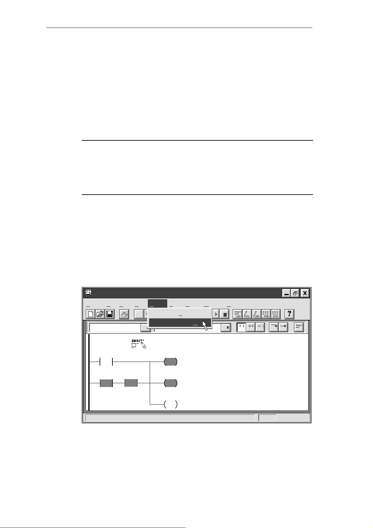
Getting Started with a Sample Program
3.8 Downloading and Monitoring the Sample Program
Once you have downloaded your program to the PDS 210, you can use the Debug features
to monitor or debug the operation of your program.
Downloading the Project to the PDS 210
The PDS 210 must be in STOP mode for you to download a program. To download your
program, select the menu command Project
you whether or not the download operation was successful.
Note
STEP 7-Micro/WIN does not verify that your program uses memory or I/O addresses that
are valid for the PDS 210 or the CPU 210. If you attempt to download a program that uses
invalid addresses or program instructions that are not supported by the PDS 210, the
PDS 210 rejects the attempt to download the program and displays an error message.
You must ensure that all memory locations, I/O addresses, and instructions used by your
program are valid for the PDS 210 and CPU 210.
"
Download... . An information message tells
Using the Ladder Editor to Monitor the Status of the Program
Ladder status shows the current state of events in your program. Reopen the Ladder Editor
window, if necessary, and select the menu command Debug
If you have an input simulator connected to the input terminals on your CPU, you can turn on
switches to see power flow and logic execution. For example, if you turn on switch I0.2, the
power flow for Network 1 will be complete when timer T0 is greater than or equal to 600. The
network will look like the one shown in Figure 3-22: M0.1 and Q0.3 are set to 1, and M0.2 is
reset to 0.
STEP 7-Micro/WIN - c:\microwin\house.prj
Project Edit View CPU Debug Tools Setup Window Help
Debug
Execute Scans...
✂
Ladder Status O
n
Contacts Normally Open
Network 1
I0.3
T0
>=I
+600
I0.2
Sound the alarm!
M0.1
S
1
Q0.3
S
1
M0.2
R
"
Ladder Status On.
F3F2
F4 F5 F8F7F6 F10
Figure 3-22 Monitoring Status of the First Network
S7-200 Programmable Controller, CPU 210
C79000-G7076-C235-01
3-23
Page 64

Getting Started with a Sample Program
Using the Status Chart to Monitor and Modify the Current Values of the Program
You can use the Status Chart to monitor or modify the current values of any I/O points or
memory locations. Reopen the Status Chart window, if necessary, and select the menu
"
command Debug
Chart Status On, as shown in Figure 3-23. As you switch inputs on or
off with the CPU in RUN mode, the Status Chart shows the current status of each element.
S To view the current value of the elements in your program, click the Single Read
button
or the Continuous Read button in the Status Chart window.
S To stop the reading of status, click the Stop button in the Status Chart window.
STEP 7-Micro/WIN - c:\microwin\house.prj
Project Edit View CPU Debug Tools Setup Window Help
Status Chart
Address Format Change Value ToCurrent PLC Value
“Zone_1”
“Zone_2”
“Armed”
“Panic_Alarm”
“LED”
“Alarm”
“Low_Alert”
“Modem”
“Alert_Timer”
“Exit_Timer”
Debug
Execute Scans...
✂
Single R
W
rite
Chart Status O
F
orce Value
Bit
Unforce Value
Bit
Bit
orce Value
F
Bit
Unforce Value
Bit
Bit
Read A
Bit
Unforce All
Bit
ead
ll Forced
n
2#0
2#0
2#0
2#0
2#0
2#0
2#0
2#0
Figure 3-23 Monitoring the Status Chart of the Sample Program
3-24
S7-200 Programmable Controller, CPU 210
C79000-G7076-C235-01
Page 65

3.9 Modifying the Sample Program
Memory
You can use the following networks of control logic to modify the sample program. These
networks provide the following enhancements to the sample program:
S If Zone 1 is open, the LED flashes one time.
S If Zone 2 is open, the LED flashes two times.
S If both zones are open, the LED flashes three times (one short flash, followed by a pause
and then two short flashes).
The modified program uses the memory addresses shown in Table 3-3. If you used symbolic
addressing with your program, add these symbolic names and addresses to the Symbol
Table.
Table 3-3 Memory Locations Used to Modify the Sample Program
Element Address Symbolic Name Description
M0.7 Blink_Bit Stores the status for the LED
Internal
Memory
Timers T1 Blink_Timer Increments the step counter
MW1 Step_Counter Tracks the blinking of the LED
MW3 Blink_Pattern Stores the pattern for flashing the LED on and off
Getting Started with a Sample Program
Creating the Blink Patterns for the LED
The program uses different bit patterns as the basis for the logic that turns the LED on and
off. Based on the condition, the program loads a value into the word that stores the blink
pattern. Figure 3-24 shows the networks that move the bit patterns into MW3. Use
STEP 7-Micro/WIN to enter the networks into the program.
Network 6
If Zone 1 is open and Zone 2 is closed, then load the
value 231 (1110011 100) in MW3
I0.1I0.0
/
Network 7
I0.0
If Zone 1 is closed and Zone 2 is open, then load the
value 165 (1010010100) in MW3
I0.1
/
Network 8
I0.0
If both Zone 1 and Zone 2 are open, then load the value
167 (1110010100) in MW3
I0.1
/
/
LAD STL
NETWORK
LDN I0.0
MOV_W
EN
IN OUT+231 MW3
MOV_W
EN
IN OUT+165 MW3
MOV_W
EN
IN OUT+167 MW3
A I0.1
MOVW +231, MW3
NETWORK
LD I0.0
AN I0.1
MOVW +165, MW3
NETWORK
LDN I0.0
AN I0.1
MOVW +167, MW3
Figure 3-24 Control Logic for Lamp Operations
S7-200 Programmable Controller, CPU 210
C79000-G7076-C235-01
3-25
Page 66

Getting Started with a Sample Program
Turning the LED On and Off
The program uses a timer (T1) and the pattern stored in MW3 to turn the LED on and off. The
program increments MW1 to count the number of passes through the control logic for flashing
the lights; after 10 passes, the MW1 is reset to 0.
Figure 3-25 shows the control logic for starting the timer. The timer starts when the system is
armed, the light-blink timer bit is not set, and either Zone 1 or Zone 2 opens.
Network 9
M0.7
Figure 3-25 Control Logic for Starting the Light-Blink Timer
If the light-blink timer bit is not set, and the system is
armed, start the light-blink timer when either Zone 1 or
Zone 2 becomes open.
I0.2
/
/
LAD STL
NETWORK
LDN M0.7
AN I0.2
I0.0
/
I0.1
+0
IN
PT
T1
TON
LDN I0.0
ON I0.1
TON T1, +0
/
Figure 3-26 shows the control logic for incrementing the count for the number of times that
the light-blink logic has been performed.
LAD STL
Network 10
T1
>=I
+4
M0.7
M0.0
R
1
If the light-blink timer is less than or
equal to 400 ms, then set the light-blink
timer bit, reset the LED bit, and
increment the step counter.
INC_W
EN
IN OUTMW1 MW1
NETWORK
LDW>= T1, +4
= M0.7
R M0.0, 1
INCW MW1
Figure 3-26 Control Logic for Setting the Timer Bit and Incrementing the Counter
Figure 3-27 shows the control logic for turning the LED on and off. Each pass through the
light-blink logic evaluates a different bit of MW3 (M4.0 to M4.7). Based on the pattern loaded
(see Figure 3-24), the LED turns on or off.
Figure 3-28 shows the control logic for resetting the count.
3-26
S7-200 Programmable Controller, CPU 210
C79000-G7076-C235-01
Page 67

Network 11
MW1
==I
+1
==I
+2
==I
+3
==I
+6
==I
+7
LAD STL
M4.0 I0.2
/
M4.1MW1
If the step counter equals a particular
M4.2MW1
M4.5MW1
M4.6MW1
value and the corresponding bit pattern
is on, set the LED bit if the system is
not armed.
Getting Started with a Sample Program
NETWORK
M0.0
S
1
LDW= MW1, +1
A M4.0
LDW= MW1, +2
A M4.1
LDW= MW1, +3
A M4.2
LDW= MW1, +6
A M4.5
LDW= MW1, +7
A M4.6
LDW= MW1, +8
A M4.7
OLD
AN I0.2
S M0.0, 1
M4.7MW1
==I
+8
Figure 3-27 Control Logic for Controlling the Blink Pattern
LAD STL
Network 12
MW1
>=I
+10
I0.0
If the step counter equals 10 and both Zone 1 and
Zone 2 are closed, then reset the step counter to 0.
MOV_W
EN
IN OUT+0 MW1
I0.1
Figure 3-28 Control Logic for Resetting the Counter
NETWORK
LDW>= MW1, +10
LD I0.0
A I0.1
OLD
MOVW +0, MW1
S7-200 Programmable Controller, CPU 210
C79000-G7076-C235-01
3-27
Page 68

Getting Started with a Sample Program
3-28
S7-200 Programmable Controller, CPU 210
C79000-G7076-C235-01
Page 69

Basic Concepts for Programming the CPU 210
Before you start to program your application using the CPU 210, you should become familiar
with some of its basic operational features.
Chapter Overview
Section
4
Description Page
4.1 Guidelines for Designing a Micro PLC System 4-2
4.2 Concepts for Creating a Program 4-4
4.3 Understanding the Scan Cycle of the CPU 210 4-6
4.4 Understanding the Programming Languages 4-9
4.5 Understanding the Addresses of the Memory Areas 4-11
4.6 Sample Program Using an Interrupt Routine 4-14
4.7 Using the Analog Adjustment Potentiometer 4-16
S7-200 Programmable Controller, CPU 210
C79000-G7076-C235-01
4-1
Page 70

Basic Concepts for Programming the CPU 210
4.1 Guidelines for Designing a Micro PLC System
There are many methods for designing a Micro PLC system. This section provides some
general guidelines that can apply to many design projects. Of course, you must follow the
directives of your own company’s procedures and of the accepted practices of your own
training and location. Figure 4-1 shows some of the basic steps in the design process.
Partition your process or machine.
Create the functional specifications of the units.
Design the hard-wired safety circuits.
Specify the operator stations.
Create the PLC configuration drawings.
Create a list of symbolic signal-naming conventions (optional).
Figure 4-1 Basic Steps for Planning a PLC System
Partitioning Y our Process or Machine
Divide your process or machine into sections that have a level of independence from each
other. These partitions will determine the boundaries between controllers and will influence
the functional description specifications and the assignment of resources.
Creating the Functional Specifications
Write the descriptions of operation for each section of the process or machine. Include the
following topics:
S Input/output (I/O) points
S Functional description of the operation
S Permissives (states that must be achieved before allowing action) for each actuator
(solenoids, motors, drives, etc.)
S Description of the operator interface
S Interfaces with other sections of the process or machine
4-2
S7-200 Programmable Controller, CPU 210
C79000-G7076-C235-01
Page 71

Designing the Safety Circuits
Identify equipment requiring hard-wired logic for safety . Control devices can fail in an unsafe
manner, producing unexpected startup or change in the operation of machinery. Where
unexpected or incorrect operation of the machinery could result in physical injury to people
or significant property damage, consideration should be given to to the use of
electro-mechanical overrides which operate independently of the CPU 210 to prevent unsafe
operations.
The following tasks should be included in the design of safety circuits:
S Identify improper or unexpected operation of actuators that could be hazardous.
S Identify the conditions that would assure the operation is not hazardous, and determine
how to detect these conditions independently of the CPU 210.
S Identify how the CPU 210 and its I/O will affect the process when power is applied and
removed, and on detected errors. This information should only be used for designing for
the normal and expected off-normal operation, and should not be relied on for safety
purposes.
S Design manual or electro-mechanical safety overrides that will block the hazardous
operation independent of the CPU.
S Provide appropriate status information from the independent circuits to the CPU 210 so
that the program and any operator interfaces have necessary information.
S Identify any other safety-related requirements for safe operation of the process.
Basic Concepts for Programming the CPU 210
Specifying the Operator Stations
Based on the requirements of the functional specifications, create drawings of the operator
station. Include the following items:
S Overview showing the location of each operator station in relation to the process or
machine
S Mechanical layout of the devices (display , switches, lights, etc.) for the operator station
S Electrical drawings with the associated I/O of the CPU 210
Creating the PLC Configuration Drawings
Based on the requirements of the functional specification, create configuration drawings of
the control equipment. Include the following items:
S Overview showing the location of the CPU in relation to the process or machine
S Mechanical layout of the CPU 210 (including cabinets and other equipment)
S Electrical drawings for each CPU 210 (including the device model numbers and I/O
addresses)
Creating a List of Symbolic Names
If you choose to use symbolic names for addressing, create a list of symbolic names for the
absolute addresses. Include not only the physical I/O signals, but also the other elements
that will be used in your program.
S7-200 Programmable Controller, CPU 210
C79000-G7076-C235-01
4-3
Page 72

Basic Concepts for Programming the CPU 210
4.2 Concepts for Creating a Program
Relating the Program to Inputs and Outputs
Figure 4-2 shows a simple diagram of how an electrical relay diagram relates to the
CPU 210. In this example, the state of the operator panel switch for opening the drain is
added to the states of other inputs. The calculations of these states then determine the state
for the output that goes to the solenoid that closes the drain. The CPU continuously cycles
through the program, reading and writing data.
The execution of the program follows a simplified flow of information: the state of the physical
input is copied to the memory area ' the CPU 210 executes the program ' whenever the
program modifies an output, the CPU 210 immediately updates the physical output. Each
memory area is assigned a mnemonic identifier (such as “I” for input) that is used for
accessing the data stored in that area of memory .
Opn_Drn_PB
Drain_Sol
Cls_Drn_PB A_Mtr_Fbk Drain_SolE_Stop_On
Figure 4-2 Relating the Program to Inputs and Outputs
Accessing Data in the Memory Areas
All of the memory areas of the CPU 210 have “absolute” addresses. You access a specific
location by entering an address (such as I0.0 for the first input point). An absolute address
for a memory area includes not only the area identifier (such as “M”), but also the size of data
to be accessed: W (word: two bytes). (The CPU 210 provides 3 words or 48 bits for the
M memory area.) The absolute address also includes a numeric value: either the number of
bytes from the beginning of the memory area (offset) or the device number . (This value is
dependent on the area identifier. See Section 4.5.)
Input
Area
CPU 210
Output
Input
S
Drain Solenoid
Operator Station
4-4
S7-200 Programmable Controller, CPU 210
C79000-G7076-C235-01
Page 73

Organizing the Program
As shown in Figure 4-3, a program for the CPU 210 is structured into the following
organizational elements: the main program and an optional hardware interrupt routine.
S The main program stores the instructions that control your application. The instructions in
the main program are executed sequentially once per scan of the CPU. To terminate the
main program, use an Unconditional End coil in ladder or a main program end instruction
(MEND) in STL.
S The CPU 210 also allows one optional hardware interrupt routine. If you use the interrupt
routine in your program, the CPU executes these instructions on a specific hardware
event (the rising edge when I0.0 turns on). Place the interrupt routine after the end of
the main program (following the Unconditional End (MEND) instruction). Use a Return
From Interrupt (RETI) instruction to terminate the interrupt routine.
Section 4.6 provides an example of a program using an interrupt routine. The interrupt
routine is not executed as part of the normal scan cycle, but is executed when the
interrupt event occurs (which may be at any point in the scan cycle).
For additional information about designing and entering a program, see the sample
application in Chapter 3.
Basic Concepts for Programming the CPU 210
Main Program
.
.
.
User Program
MEND
Interrupt Routine (optional)
RETI
Figure 4-3 Program Structure for the CPU 210
Main Program:
Executed once per scan
Interrupt Routine:
Executed on each occurrence of the
interrupt event
S7-200 Programmable Controller, CPU 210
C79000-G7076-C235-01
4-5
Page 74

Basic Concepts for Programming the CPU 210
4.3 Understanding the Scan Cycle of the CPU 210
The basic operation of the CPU 210 is very simple:
S The CPU reads the status of the inputs.
S The program that is stored in the CPU uses the inputs to evaluate the control logic. As
the program runs, the CPU writes the data to the outputs.
The CPU 210 continuously executes your program. If your program uses the optional
hardware interrupt routine, the interrupt routine can run anytime after the CPU executes the
Enable Interrupt (ENI) instruction in the main program segment.
Understanding the Basic Scan Cycle of the CPU 210
The CPU 210 executes your program in a continuous, cyclical series of tasks called a scan.
As shown in Figure 4-4, the CPU 210 performs the following tasks during the scan cycle:
1. During the first scan (after power is turned on) only , the CPU 210 clears the outputs (Q),
bit memory (M) area, and the current values for the timers (T). The CPU 210 clears these
elements only during the first scan.
If a memory cartridge is not installed, the CPU 210 restores the current values for the four
counters.
2. The CPU 210 filters the inputs and updates the value of the analog adjustment
potentiometer (stored in SMW2). This delays the scan by approximately 15 ms.
3. The CPU 210 executes the user program. As the program writes values to the outputs,
the CPU 210 immediately updates the outputs.
4. The CPU 210 updates the time base for the 100 ms timers.
The interrupt routine is not executed as part of the normal scan cycle, but is executed when
the interrupt event occurs (which may be at any point in the scan cycle). After the Enable
Interrupt (ENI) instruction in the main program segment has been executed, the CPU 210
executes the interrupt routine on the rising edge of I0.0. The CPU 210 can run the interrupt
routine any time within the scan cycle.
4-6
After the interrupt routine has been enabled, interrupt events can start
the interrupt routine at any time in the scan,
CPU Tasks
Clear the outputs.
Clear M memory.
Clear the current values for
the timers.
First Scan Only
Read the filtered inputs.
Update the analog
potentiometer value.
Figure 4-4 Scan Cycle for the CPU 210
Execute the program.
Write the outputs.
All Scans
S7-200 Programmable Controller, CPU 210
Update the time base
for the timers.
C79000-G7076-C235-01
Page 75
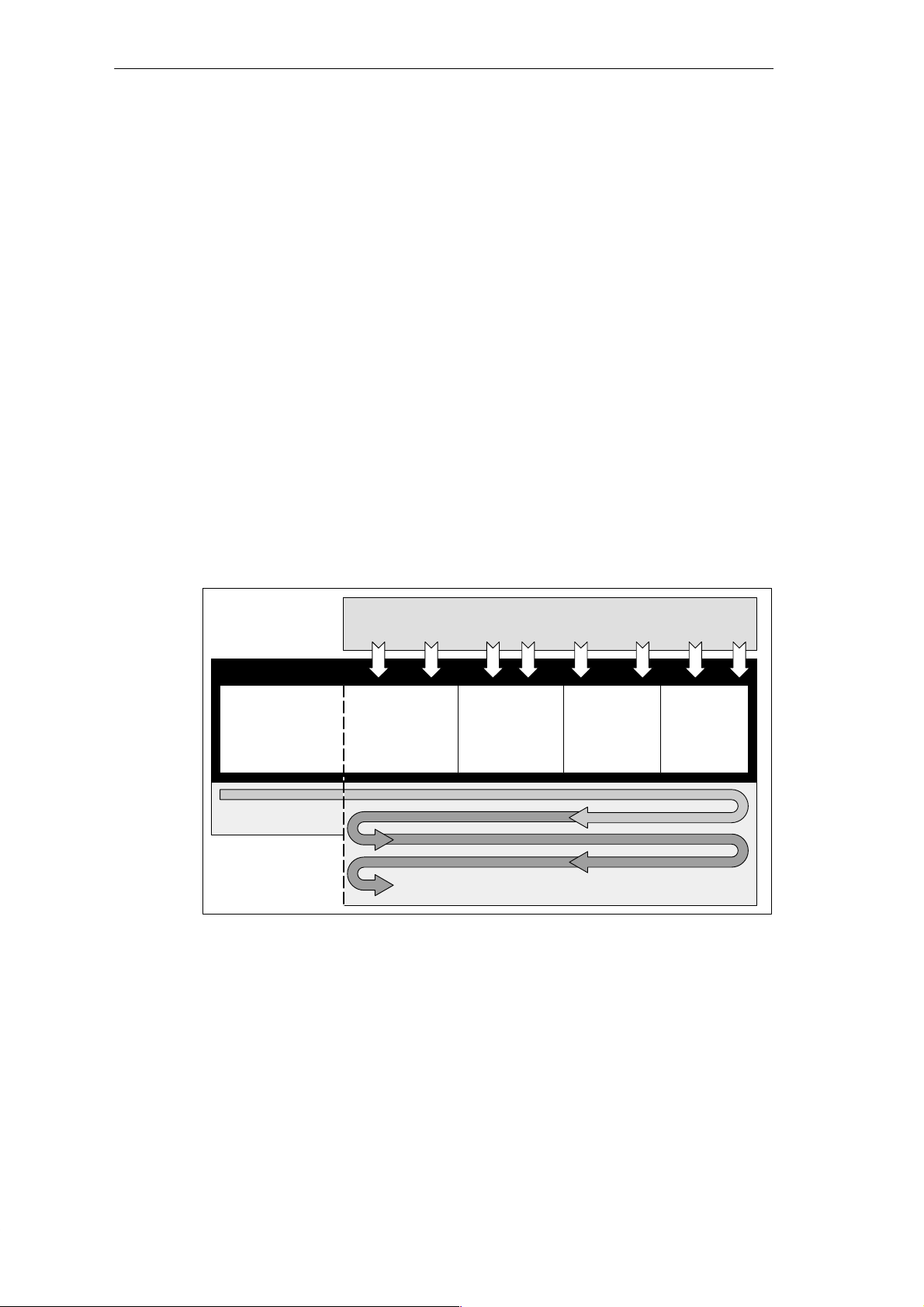
Understanding the Basic Scan Cycle of the PDS 210
The scan cycle for the PDS 210 is similar to the scan cycle for the CPU 210. Because the
PDS 210 communicates with STEP 7-Micro/WIN, it must process any communication
requests. The PDS 210 also updates the timers before executing the program, which is
different from the CPU 210.
As shown in Figure 4-5, the PDS 210 performs the following tasks during the scan cycle:
1. During the first scan (after power is turned on) only , the PDS 210 clears the outputs (Q),
bit memory (M) area, and the current values for the timers (T). The PDS 210 clears these
elements only during the first scan.
2. The PDS 210 filters the inputs and updates the value of the analog adjustment
potentiometer (stored in SMW2). This delays the scan by approximately 15 ms.
3. The PDS 210 updates the time base for the 100 ms timers. (Notice that the PDS 210
updates the timers before executing the program.)
4. The PDS 210 executes the user program. As the program writes values to the outputs,
the PDS 210 immediately updates the outputs.
5. The PDS 210 processes any communication requests from STEP 7-Micro/WIN.
The interrupt routine is not executed as part of the normal scan cycle, but is executed when
the interrupt event occurs (which may be at any point in the scan cycle). After the Enable
Interrupt (ENI) instruction in the main program segment has been executed, the PDS 210
executes the interrupt routine on the rising edge of I0.0. The PDS 210 can run the interrupt
routine any time within the scan cycle.
Basic Concepts for Programming the CPU 210
After the interrupt routine has been enabled, interrupt events can start the
interrupt routine at any time in the scan,
PDS Tasks
Clear the outputs.
Clear M memory.
Clear the current
values for the timers.
First Scan Only
Read the filtered
inputs.
Update the analog
potentiometer value.
Figure 4-5 Scan Cycle for the PDS 210
Update the time
base for the timers.
All Scans
Execute the
program.
Write the outputs.
Process any
communication
requests.
S7-200 Programmable Controller, CPU 210
C79000-G7076-C235-01
4-7
Page 76

Basic Concepts for Programming the CPU 210
Using the Debug Option to Specify the Number of Scans
STEP 7-Micro/WIN allows you to debug your program by specifying a number of scans to be
run on the PDS 210 before stopping. (See Section 2.9.) You can specify to run one scan or
several. The PDS 210 executes the first scan as if power were just turned on. At the end of
the specified number of scans, all of the outputs are cleared.
You can only use the debug option with the PDS 210.
As shown in Figure 4-6, the PDS 210 performs the following tasks when debugging a
program:
1. During the first scan only , the PDS 210 clears the outputs (Q), bit memory (M) area, and
the current values for the timers (T).
2. The PDS 210 filters the inputs and updates the value of the analog adjustment
potentiometer (stored in SMW2).
3. The PDS 210 updates the time base for the 100 ms timers.
4. The PDS 210 executes the user program. As the program writes values to the outputs,
the PDS 210 immediately updates the outputs.
5. The PDS 210 processes any communication requests from STEP 7-Micro/WIN.
6. If you specified more than 1 scan, the PDS 210 starts the next scan, starting with Step 2.
7. After the specified number of scans have been run, the PDS 210 clears all outputs and
disables the hardware interrupt.
After the interrupt routine has been enabled, interrupt events can start
the interrupt routine at any time in the scan,
PDS Tasks
Clear the outputs.
Clear M memory.
Clear the current
values for the timers.
Read the filtered
inputs.
Update the analog
potentiometer value.
Update the time
base for the
timers.
Single Scan
The PDS 210
executes the
number of
scans specified
by the software
Multiple Scans
Figure 4-6 Scan Cycle for the Debug Option
Execute the
program.
Write the outputs.
Process any
communication
requests.
Clear the outputs.
4-8
S7-200 Programmable Controller, CPU 210
C79000-G7076-C235-01
Page 77

Basic Concepts for Programming the CPU 210
4.4 Understanding the Programming Languages
The CPU 210 and STEP 7-Micro/WIN support the following programming languages:
S Statement list (STL) is a set of mnemonic instructions that represent functions of the
CPU.
S Ladder is a graphical language that resembles the electrical relay diagrams for the
equipment.
STEP 7-Micro/WIN also provides two representations for displaying the addresses and the
programming instructions in the program: International and SIMA TIC. Both the international
and SIMA TIC representations refer to the same CPU 210 instruction set. There is a direct
correspondence between the International and the SIMA TIC representation; both
representations have the same functionality .
Understanding the Basic Elements of Ladder
When you write a program in ladder, you create and arrange the graphical components to
form a network of logic. As shown in Figure 4-7, the following types of elements are available
for creating your program:
S Contacts: each of these elements represents a switch through which power can flow
when a switch is closed.
S Coils: each of these elements represents a relay that is energized by power flowing to
that relay .
S Boxes: each of these elements represents a function that is executed when power flows
to the box.
S Networks: this element forms a complete circuit. Power flows from the left power rail
through the closed contacts to energize the coils or boxes.
Output Coils Output
Network 1
I0.0
Normally Open
Contact
Network 2
Left Power Rail
NETWORK TITLE (single line)
I0.1 Q0.0
Normally Closed
Contact
NETWORK TITLE (single line)
T0I0.0
+0
IN
PT
TON
Figure 4-7 Basic Elements of Ladder
Box
Coil
F3F2
F4 F5 F8F7F6 F10
Network
Network
S7-200 Programmable Controller, CPU 210
C79000-G7076-C235-01
4-9
Page 78

Basic Concepts for Programming the CPU 210
Understanding the Statement List Instructions
Statement list (STL) is a programming language in which each statement in your program
includes an instruction that uses a mnemonic abbreviation to represent a function of the
CPU. You combine these instructions into a program to produce the control logic for your
application. Figure 4-8 shows the basic elements of a statement list program.
STL
STL Editor - project1.ob1
//Conveyor Line Program
NETWORK 1 //Start Motor:
LD “Start1” //When I0.0 is on
AN “E-Stop1” //and I0.1 is not on,
= Q0.0 //then turn on conveyor motor.
NETWORK 2 //End of Program
MEND
Instruction
Figure 4-8 STL Editor Window with Sample Program
The STL instructions use a logic stack for solving your control logic. As shown in Figure 4-9,
this logic stack is eight bits deep by one bit wide. Most of the STL instructions work either
with the first bit or with the first and the second bits of the logic stack. New values can be
“pushed” (or added) onto the stack; when the top two bits of the stack are combined, the
stack is “popped” (reduced by one bit).
While most STL instructions only read the values in the logic stack, many STL instructions
also modify the values stored in the logic stack. Figure 4-9 shows three examples of how
three instructions use the logic stack.
Operand
Begin each comment with
a double slash (//).
Bits of the Logic Stack
Load (LD)
Loads a new value (nv) onto the
stack.
Before Load After Load
iv0
iv1
iv2
iv3
iv4
iv5
iv6
iv7
In these examples, “iv0” to “iv7” identify the initial values of the logic stack, “nv” identifies a new value provided by the instruction, and
“S0” identifies the calculated value that is stored in the logic stack.
nv
iv0
iv1
iv2
iv3
iv4
iv5
iv6
iv7 is lost.
S0
S1
S2
S3
S4
S5
S6
S7
Stack 0 - First stack level, or top of the stack
Stack 1 - Second stack level
Stack 2 - Third stack level
Stack 3 - Fourth stack level
Stack 4 - Fifth stack level
Stack 5 - Sixth stack level
Stack 6 - Seventh stack level
Stack 7 - Eighth stack level
And (A)
ANDs a new value (nv) with the top
of stack.
S0 = iv0 * nv
Before And After And
iv0
iv1
iv2
iv3
iv4
iv5
iv6
iv7
S0
iv1
iv2
iv3
iv4
iv5
iv6
iv7
Or (O)
ORs a new value (nv) with the top
of stack.
S0 = iv0 + nv
Before Or After Or
iv0
iv1
iv2
iv3
iv4
iv5
iv6
iv7
S0
iv1
iv2
iv3
iv4
iv5
iv6
iv7
Figure 4-9 Logic Stack of the CPU 210
4-10
S7-200 Programmable Controller, CPU 210
C79000-G7076-C235-01
Page 79

Basic Concepts for Programming the CPU 210
4.5 Understanding the Addresses of the Memory Areas
The CPU 210 provides 4 digital input points and 4 digital output points. In addition to the I/O,
the CPU provides memory areas for storing information. These memory locations have
unique addresses that can be accessed by your program. Figure 4-10 shows the memory
areas and the range of addresses for the CPU 210.
Internal Memory
Bit Memory Area Timers Special Memory
M0.0 to M0.7
Inputs and Outputs
I0.0 Q0.0
I0.1 Q0.1
I0.2 Q0.2
I0.3 Q0.3
M1.0 to M1.7
M2.0 to M2.7
M3.0 to M3.7
M4.0 to M4.7
M5.0 to M5.7
Figure 4-10 Memory Addresses for the CPU 210
Accessing the data in words (16-bit units) allows the following ranges of integer values:
S Unsigned Integer: 0 to 65,535 (decimal)
0 to FFFF (hexadecimal)
S Signed Integer: -32,768 to +32,767 (decimal)
8000 to 7FFF (hexadecimal)
Using the Memory Address to Access Data
To access a bit in a memory area, you specify the address, which includes the memory area
identifier, the byte address, and the bit number. Figure 4-11 shows an example of addressing
a bit (which is also called “byte.bit” addressing). In this example, the memory area and byte
address (M=bit memory area, and 3=byte 3) are followed by a period (“.”) to separate the bit
address (bit 4).
T0
T1
T2
T3
Counters
C0
C1
C2
C3
SM0.0 to SM0.7
SM1.0 to SM1.7
Analog Adjustment
SMW2
.
M3 4
Bit of byte, or bit number: bit 4 of 8 (0 to 7)
Period separates the byte address
from the bit number
Byte address: byte 3 (the fourth byte)
Area identifier (M = bit memory area)
MSB = most significant bit,and LSB = least significant bit
Figure 4-11 Accessing a Bit of Data in the CPU Memory (Byte.Bit Addressing)
S7-200 Programmable Controller, CPU 210
C79000-G7076-C235-01
MSB LSB
76543210
M 0
M 1
M 2
M 3
M 4
M 5
4-11
Page 80

Basic Concepts for Programming the CPU 210
You can access data in many CPU memory areas (T, C, M, and SM) as words. To access a
word of data in the CPU memory , you must specify the address in a similar way to the
address for a bit. This includes an area identifier, data size designation, and the starting byte
address of the value, as shown in Figure 4-12. Timer (T) and counter (C) data are accessed
by using an address format that includes an area identifier and a device number.
Most significant byte
MSB
15 8
MW2 MB2 MB3
Figure 4-12 Accessing a Word of Data in the CPU Memory
Addressing the Input Image Register (I)
As described in Section 4.2, the CPU samples the physical input points at the beginning of
each scan cycle and writes the filtered values to the input image register.
Format: Bit I0
Addressing the Outputs (Q)
When the control logic of the program turns an output coil on, the CPU immediately turns that
output on.
Format: Bit Q0
Addressing the Bit Memory (M) Area
You can use the internal memory bits (M memory) as control relays to store the intermediate
status of an operation or other control information.
Format: Bit M
Word M
Least significant byte
70
LSB
MW2
Byte address
Access to a word size
Area identifier (M memory)
.[bit address]
.[bit address]
[byte address].[bit address]
[size][starting byte address]
I0.1
Q0.0
M2.7
MW0
Addressing the Special Memory (SM) Bits
The SM bits provide a means for communicating information between the CPU and your
program. You can use these bits to select and control some of the special functions of the
CPU 210, such as a bit that turns on for the first scan, bits that toggle at fixed rates, or a word
that stores the value of the analog adjustment potentiometer.
For more information about the SM bits, see Appendix B. While the SM area is based on bits,
you can access the data in this area as bits or (for the analog adjustment) a word.
Format: Bit SM
Word SM
4-12
[byte address].[bit address]
SM0.1
[size][starting byte address]
S7-200 Programmable Controller, CPU 210
C79000-G7076-C235-01
SMW2
Page 81

Addressing the Timer (T) Memory Area
Timers are devices that count increments of time. The four timers (T0 to T3) have resolutions
(time-base increments) of 100 ms. The current value of each timer is stored as a 16-bit
(word) signed integer. You access the current value by using the timer address (T + timer
number).
Format: T
Addressing the Counter (C) Memory Area
Counters are devices that count each low-to-high transition event on the counter input(s).
The four counters (C0 to C3) provided by the CPU 210 count both up and down. The current
value of each counter stores the accumulated count as a 16-bit (word) signed integer.
Format: C
Using Constant Values
Many of the programming instructions for the CPU 210 allow you to use constant values.
These constants can only be word-length, signed integers. The CPU stores all constants as
binary numbers, which can then be represented in decimal, hexadecimal, or ASCII formats.
Decimal Format: [decimal value]
Hexadecimal Format: 16#[hexadecimal value]
ASCII Format: ’[ASCII text]’
The CPU 210 does not support “data typing” or data checking (such as specifying that the
constant is stored as an integer or a signed integer) and does not check for a certain data
type. For example, an LDW>= instruction can use the value in MW2 as a signed integer
value, while a MOVW instruction can use the same value in MW2 as an unsigned binary
value.
The following examples show constants for decimal, hexadecimal, and ASCII format:
S Decimal constant: 20047
S Hexadecimal constant: 16#4E4F
S ASCII constant: ’AD’ (ASCII text goes between the apostrophes—also known
as “single-quote marks.”)
Basic Concepts for Programming the CPU 210
[timer number]
[counter number]
T0
C2
S7-200 Programmable Controller, CPU 210
C79000-G7076-C235-01
4-13
Page 82

Basic Concepts for Programming the CPU 210
4.6 Sample Program Using an Interrupt Routine
You can use the hardware interrupt of the CPU 210 to control tasks that require high-speed
counting functions. For example, you can use the CPU 210 to count a pulse train from an
RTD sensor instrument and control a resistance heater. Figure 4-13 shows a sample
application for the following tasks:
1. An instrument (such as a PT100 RTD sensor) measures the temperature, and an RTD
module generates an output pulse train that is proportional to the temperature.
2. Using the hardware interrupt event (the rising edge of I0.0), the CPU 210 counts the
pulses that it receives over a period of time (5 seconds). Based on the count (which
relates to the temperature), the CPU 210 turns a digital output on or off.
3. The power contactor turns the resistance heater on or off, based on the state of the
output of the CPU 210.
Figure 4-14 shows a sample program for this application example. This example counts up
to 3 kHz.
1.
Temperature measurement (using a PT100 RTD sensor)
The RTD module converts the temperature to a pulse train.
Heater operation
Counts per 5 seconds
(relates to temperature)
30000
15200
OFF
ON
0
3.
The power contactor controls the
resistance heating element.
2.
The program in the CPU 210 monitors
the temperature and controls the heat
source.
Figure 4-13 Sample Application Using the Hardware Interrupt
Pulse train waveform
(up to 3 kHz)
4-14
S7-200 Programmable Controller, CPU 210
C79000-G7076-C235-01
Page 83
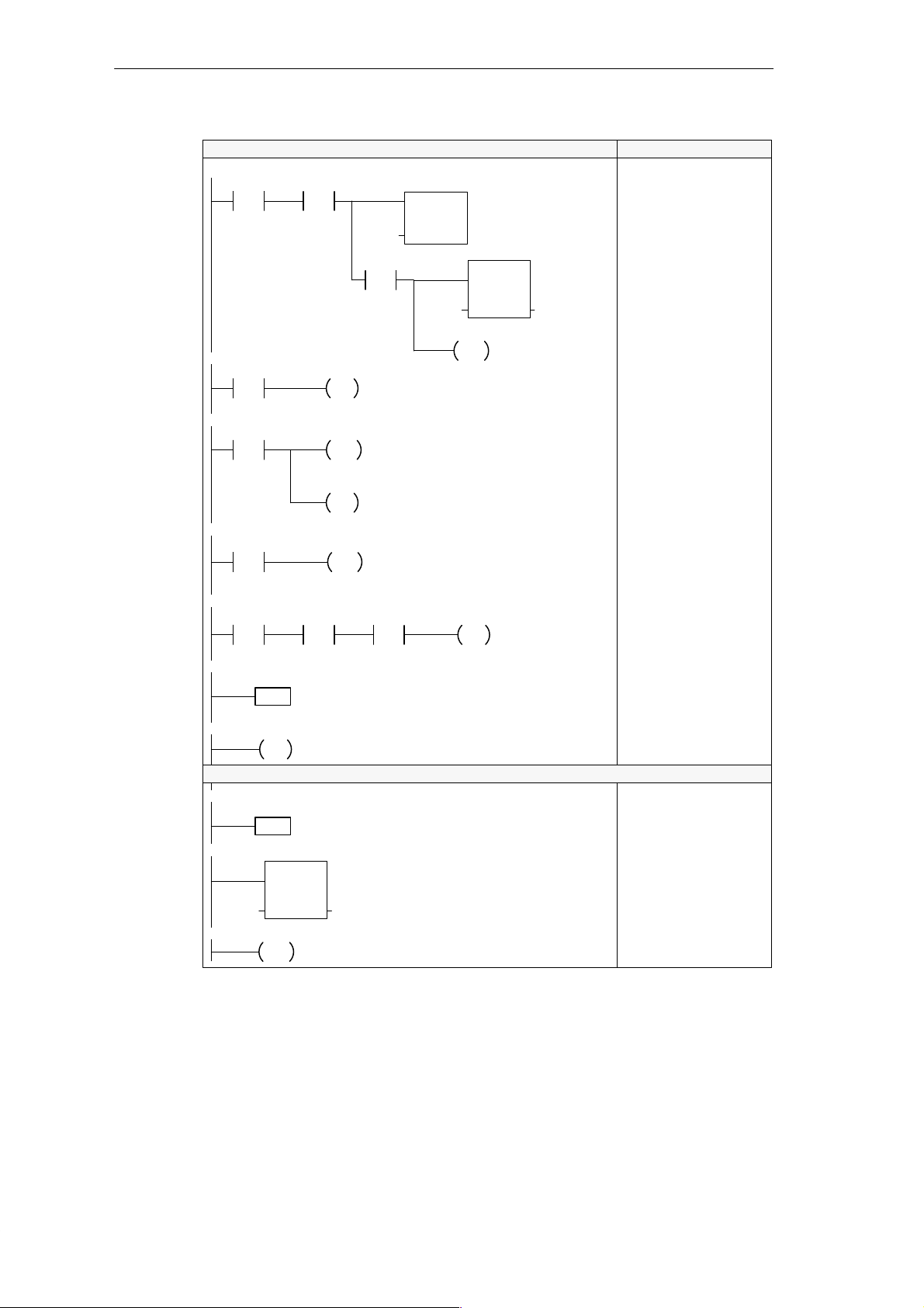
Basic Concepts for Programming the CPU 210
Network 1
I0.1
Network 2
SM0.0
Network 3
T0
>=I
+50
Network 4
M0.0
Network 5
M0.0 I0.1
/
Network 6
Network 7
Network 8
Network 9
Network 10
0
LBL
END
0
INT
EN
IN OUTMW2 MW2
RETI
Main Program
M0.0
M0.0
S
1
DISI
M0.0
R
1
0
JMP
Interrupt Routine
INC_W
Ladder STL
T0
TON
IN
PT
+0
MOV_W
P
Network 1: Turn on timer T0, enable the
interrupt routine, and initialize the counter
variable (MW2).
Network 2: Turn the timer on after it has
been turned off.
Network 3: After 5 seconds, turn off the
timer and disable the interrupt routine.
Network 4: While the timer is executing,
jump over the logic that tests the number
of counts.
Network 5: If timer has stopped, turn on
Q0.0 if the number of counts is less than
or equal to 15200.
MW2
<=I
+15200
Network 6: Destination for the jump
instruction (Network 4).
Network 7: End of the main program
segment.
Network 8: Identifies the high-speed
counter interrupt routine. This interrupt
routine can count up to 3 kHz.
Network 9: Increments the counter (MW2)
for each positive transition of I0.0.
Network 10: Returns to the main program
segment.
EN
IN OUT+0 MW2
ENI
Q0.0
Network 1
LD I0.1
A M0.0
TON T0, +0
EU
MOVW +0, MW2
ENI
Network 2
LD SM0.0
S M0.0, 1
Network 3
LDW>= T0, +50
DISI
R M0.0, 1
Network 4
LD M0.0
JMP 0
Network 5
LDN M0.0
A I0.1
AW<= MW2, +15200
= Q0.0
Network 6
LBL 0
Network 7
MEND
Network 8
INT 0
Network 9
INCW MW2
Network 10
RETI
Figure 4-14 Using an Interrupt Routine to Provide a High-Speed Counter
S7-200 Programmable Controller, CPU 210
C79000-G7076-C235-01
4-15
Page 84

Basic Concepts for Programming the CPU 210
4.7 Using the Analog Adjustment Potentiometer
As shown in Figure 4-15, your CPU 210 provides one analog adjustment potentiometer
(located under the access cover of the module). You can adjust this potentiometer to
increase or decrease values which are stored in bytes of Special Memory (SMW2). Your
program can use this read-only value for a variety of functions, such as updating the current
value for a timer or a counter, entering or changing the preset values, or setting limits.
You use a small screwdriver to make the adjustments: turn the potentiometer clockwise (to
the right) to increase the value, and counter-clockwise (to the left) to decrease the value.
Analog Adjustment
potentiometer
DC
OUTPUTS
M L+ 0.0 0.1 0.2 0.3
↓ M L+ 24V DC
Figure 4-15 Analog Adjustment Potentiometer
SMW2 stores the digital value that represents the position of the analog adjustment
potentiometer.
The CPU 210 samples the analog adjustment potentiometer at least three times a second
and has a range from 0 to 255. The new value of the analog adjustment potentiometer is
written to SMW2 at the beginning of the next scan.
The analog adjustment potentiometer on the PDS 210 has a nominal range of 0 to 255, with
a guaranteed range of 10 to 200.
Figure 4-16 shows a sample program that uses the value entered with the analog adjustment
potentiometer.
STL
Network 1
I0.0
Network 2
M2.0
/
Network 3
T0
>=I
MW0
MOV_W
EN
IN OUTSMW2 MW0
T0
IN
PT
+0
M2.0
TON
LAD
Read the analog adjustment
value and store that value in
MW0.
Start timer T0.
Turn on M2.0 when T0
reaches the value entered
with the analog adjustment.
Network 1
LD I0.0
MOVW SMW2, MW0
Network 2
LDN M2.0
TON T0, 0
Network 3
LDW>= T0, MW0
= M2.0
4-16
Figure 4-16 Sample Program for Using the Analog Adjustment
S7-200 Programmable Controller, CPU 210
C79000-G7076-C235-01
Page 85

Instruction Set
The following conventions are used in this chapter to illustrate the equivalent ladder and
statement list instructions:
5
A
D
S
Chapter Overview
Section
L
T
=n
L
5.1 Valid Ranges for the CPU 210 and PDS 210 5-2
5.2 Contact Instructions 5-3
5.3 Output Instructions 5-5
5.4 Timer Instructions 5-6
5.5 Counter Instructions 5-8
5.6 Increment and Decrement Instructions 5-9
5.7 Move Instruction 5-10
5.8 Program Control Instructions 5-11
5.9 Logic Stack Instructions 5-13
5.10 Interrupt Instructions 5-14
n
Ladder (LAD)
representation
Statement list (STL)
representation
Description Page
Conditional: executes
according to condition of
preceding logic
Unconditional: executes
without preceding logic
JMP
END
S7-200 Programmable Controller, CPU 210
C79000-G7076-C235-01
5-1
Page 86

Instruction Set
5.1 Valid Ranges for the CPU 210 and PDS 210
Valid Operand Ranges
Table 5-1 provides the valid ranges of the operands used to access data in the different
memory areas. These ranges vary according to the size of the data being accessed.
Table 5-1 Operand Ranges
Access Method
Bit Access
(Byte.bit)
Word Access T 0 to 3
I 0.0 to 0.3
Q 0.0 to 0.3
M 0.0 to 5.7
SM 0.0 to 1.7
C 0 to 3
MW 0 to 4
SMW 0 to 2
Constant
CPU 210 and PDS 210
5-2
S7-200 Programmable Controller, CPU 210
C79000-G7076-C235-01
Page 87

5.2 Contact Instructions
Standard Contacts
L
A
D
S
LD n
T
An
L
On
LDN n
AN n
ON n
n
n
/
Instruction Set
The Normally Open contact is closed (on) when the bit value of
address n = 1.
In STL, the normally open contact is represented by the Load,
And, and Or instructions. These instructions Load, AND, or OR
the bit value of address n to the top of the stack.
The Normally Closed contact is closed (on) when the bit value
of address n = 0.
In STL, the normally closed contact is represented by the Load
Not, And Not, and Or Not instructions. These instructions
Load, AND, or OR the logical Not of the bit value of address n to
the top of the stack.
Operands: n: I, M, SM
These instructions obtain the referenced value from the image
register, which is updated at the beginning of each CPU scan.
Not
L
A
D
S
T
L
NOT
NOT
Positive, Negative Transition
L
A
D
P
N
S
EU
T
L
ED
You can have a total of 32 transition instructions in a program. These can be any
combination of Positive Transition (EU) and Negative T ransition (ED) instructions.
The Not contact changes the state of power flow. When power
flow reaches the Not contact, it stops. When power flow does
not reach the Not contact, it sources power flow.
In STL, the Not instruction changes the value on the top of the
stack from 0 to 1, or from 1 to 0.
Operands: none
The Positive Transition contact allows power to flow for one
scan for each off-to-on transition. In STL, the Positive Transition
contact is represented by the Edge Up instruction. Upon
detection of a 0-to-1 transition in the value on the top of the
stack, the top of the stack value is set to 1; otherwise, it is set to
0.
The Negative Transition contact allows power to flow for one
scan, for each on-to-off transition. In STL, the Negative
Transition contact is represented by the Edge Down instruction.
Upon detection of a 1-to-0 transition in the value on the top of
the stack, the top of the stack value is set to 1; otherwise, it is
set to 0.
Operands: none
S7-200 Programmable Controller, CPU 210
C79000-G7076-C235-01
5-3
Page 88

Instruction Set
Compare Word Integer
L
A
D
S
LDW= n1, n2
T
AW= n1, n2
L
OW= n1, n2
LDW>= n1, n2
AW>= n1, n2
OW>= n1, n2
LDW<= n1, n2
AW<= n1, n2
OW<= n1, n2
n1
==I
n2
n1
>=I
n2
n1
<=I
n2
The Compare Word Integer instruction is used to compare two
values: n1 = n2, n1 >= n2, or n1 <= n2.
Operands: n1: T, C, MW, SMW
n2: T, C, MW, SMW, Constant
In ladder, the contact is on when the comparison is true.
In STL, the instructions Load, AND, or OR a 1 with the top of
stack when the comparison is true.
Word comparisons are signed (16#7FFF > 16#8000).
You can create a <>, <, or > comparison by using the Not
instruction with the =, >=, or <= compare instruction. The
following sequence is equivalent to a <> comparison of MW0 to
50:
LDW= MW0, 50
NOT
Contact Examples
Network 1
Network 2
Network 3
Network 4
LAD STL
NETWORK 1
I0.0 I0.1
NOT
N
>=I
MW2
I0.0
I0.1
Q0.0
Q0.1
Q0.2
MW0 >= MW2 MW0 < MW2
Q0.3
Q0.0
Q0.1I0.0
Q0.2I0.1
Q0.3MW0
Timing Diagram
LD I0.0
A I0.1
= Q0.0
NETWORK 2
LD I0.0
NOT
= Q0.1
NETWORK 3
LD I0.1
ED
= Q0.2
NETWORK 4
LDW>= MW0, MW2
= Q0.3
On for one scan
5-4
Figure 5-1 Example of Boolean Contact Instructions
S7-200 Programmable Controller, CPU 210
C79000-G7076-C235-01
Page 89

5.3 Output Instructions
Output
Set, Reset
L
A
D
S
T
L
L
A
D
=n
n
S_BIT
S
1
Instruction Set
When the Output instruction is executed, the specified
parameter (n) is turned on.
In STL, the output instruction copies the top of the stack to the
specified parameter (n).
Operands: n: Q, M
When the Set and Reset instructions are executed, the point
specified by S_BIT is set (turned on) or reset (turned off).
Output Example
S
S S_BIT, 1
T
L
R S_BIT, 1
Network 1
I0.0
S_BIT
R
1
I0.0
Operands: S_BIT: Q, M
LAD STL
NETWORK
Q0.0
Q0.1
S
1
Q0.2
R
1
Timing Diagram
LD I0.0
= Q0.0
S Q0.1, 1
R Q0.2, 1
Q0.0
Q0.1
Q0.2
Figure 5-2 Example of Output Instructions
S7-200 Programmable Controller, CPU 210
C79000-G7076-C235-01
5-5
Page 90

Instruction Set
5.4 Timer Instructions
You can use the timer to implement time-based counting functions. The timer times up while
the enabling input is on. When the enabling input is off, the timer automatically resets. The
timer is best used when you are timing a single interval.
On-Delay Timer
L
A
D
S
T
TON Tx, 0
L
Each timer has a 100-ms resolution, with a maximum value of 3276.7 seconds. Once
enabled, the timer counts up to the maximum value and stops, unless it is disabled prior to
reaching the maximum value. Disabling the timer resets the timer value to zero (0).
IN
PT
Tx
TON
The On-Delay Timer instruction times up to the maximum value
when enabled. The timer resets when disabled, and stops
timing when it reaches the maximum value (3276.7 seconds).
Operands: Tx: T0 to T3
PT: 0 (preset value is not used)
Timers in the CPU 210 do not use the preset value. The timer
counts time for as long as it is enabled. Use a Compare Word
instruction to detect the timer value.
Understanding How the CPU 210 Updates the Timers
The timers in the CPU 210 have a 100-ms resolution: each timer counts the number of
100-ms intervals that have elapsed since the timer was last updated. The timer is updated by
adding the accumulated number of 100-ms intervals (since the beginning of the previous
scan) to the current value (for that timer) when the timer instruction is executed.
The update of the timers is not automatic, since the current value of a timer is updated only if
the timer instruction is executed. Consequently , if a timer is enabled but the timer instruction
is not executed each scan, the current value for that timer will not be updated, and it will lose
time. Likewise, if the same 100-ms timer instruction is executed multiple times in a single
scan, the number of 100-ms intervals will be added to the timer’s current value multiple
times, and it will gain time. For this reason, you should use timers only where the timer
instruction will be executed exactly once per scan.
Note
The process of accumulating 100-ms intervals is performed independently of the enabling
and disabling of timers, so a given 100-ms timer will be enabled at a point somewhere
within the current 100-ms interval. This means that a timed interval for a given 100-ms
timer can be up to 100 ms short. Set the parameter for the Compare Word instruction for a
value of one greater than the minimum desired timed interval. For example, to guarantee
a timed interval of at least 2100 ms, set the value of the Compare Word instruction to 22
(2100 ms equals 21 100-ms units, plus 1 100-ms unit equals 22 100-ms units).
5-6
S7-200 Programmable Controller, CPU 210
C79000-G7076-C235-01
Page 91

Timer Example
I0.2
T1
>=I
+3
I0.2
T1 (current)
LAD STL
T1
TON
IN
0
PT
Q0.2
Timing Diagram
Network
LD I0.2
TON T1, 0
Network
LDW >= T1, 3
= Q0.2
Instruction Set
T1 >= 3
Q0.2
Figure 5-3 Example of the Timer Instruction
LAD STL
M0.0
/
T0
>=I
+30
T0
TON
IN
0
PT
M0.0
Network
LDN M0.0 //Enable/disable the timer
TON T0, 0 //Select timer T0
Network
LDW>= T0, 30 //Every 3 seconds,
= M0.0 //Turn on M0.0 (which then
//disables the timer)
Figure 5-4 Example of an Automatically Retriggered One-Shot Timer
T1 >= 3
S7-200 Programmable Controller, CPU 210
C79000-G7076-C235-01
5-7
Page 92

Instruction Set
5.5 Counter Instructions
The Up/Down Counter counts up each time the count-up input transitions from off to on, and
counts down each time the count-down input transitions from off to on. The counter resets
when the reset input turns on. Upon reaching maximum value (32,767), the next rising edge
at the count-up input will cause the current count to wrap around to the minimum value
(-32,768). Likewise on reaching the minimum value (-32,768), the next rising edge at the
count-down input will cause the current count to wrap around to the maximum value
(32,767).
The Up/Down counter has a current value that maintains the current count. Use the counter
number to reference the current value. Since there is one current value for each counter, do
not assign the same number to more than one counter.
Up/Down Counter
CU
CD
R
PV
Cx
CTUD
L
A
D
The Up/Down Counter instruction counts up on rising edges of
the Count Up (CU) input. It counts down on the rising edges of
the Count Down (CD) input. The counter resets when the Reset
(R) input turns on
In STL, the Reset input is the top of the stack value, the Count
Down input is the value loaded in the second stack location,
and the Count Up input is the value loaded in the third stack
location.
S
T
L
Counter Example
CTUD Cx, PV
I0.3
I0.2
I0.1
0
C1
>=I
+4
Operands: Cx: C0 to C3
PV: 0 (preset value is not used)
LAD STL
C1
CTUD
CU
CD
R
PV
Q0.2
I0.3 Up
I0.2 Down
I0.1 Reset
C1 Current
Q0.2
1
0
Network
LD I0.3 //Count Up Clock
LD I0.2 //Count Down Clock
LD I0.1 //Reset
CTUD C1, 0
Network
LDW>= C1, 4
= Q0.2
Timing Diagram
5
4
3
2
4
4
3
5
5-8
Figure 5-5 Example of the Counter Instruction
S7-200 Programmable Controller, CPU 210
C79000-G7076-C235-01
Page 93

5.6 Increment and Decrement Instructions
Increment Word, Decrement Word
L
A
D
S
INCW OUT
T
L
DECW OUT
INC_W
EN
IN OUT
DEC_W
EN
IN OUT
The Increment Word and Decrement Word instructions add or
subtract 1 to or from the input word.
Operands: IN: T, C, MW
OUT: T, C, MW
In ladder: IN + 1 = OUT
IN - 1 = OUT
In STL: OUT + 1 = OUT
OUT - 1 = OUT
Increment and decrement word operations are signed
(16#7FFF > 16#8000).
When programming in ladder, if you specify the address for IN
to be the same address as OUT, you can reduce the amount of
memory required.
These instructions affect the following Special Memory bits:
SM1.0 (zero); SM1.1 (overflow); SM1.2 (negative)
Instruction Set
Increment, Decrement Example
I0.0
Figure 5-6 Example of Increment/Decrement Instructions
LAD STL
INC_W
EN
INMW0 OUT
DEC_W
EN
INMW2 OUT MW2
Increment Word Decrement Word
MW0
MW0
MW0
Application
125
increment
126
MW2
MW2
Network
LD I0.0
INCW MW0
DECW MW2
5000
decrement
4999
S7-200 Programmable Controller, CPU 210
C79000-G7076-C235-01
5-9
Page 94

Instruction Set
5.7 Move Instruction
Move Word
Move Examples
L
A
D
S
T
L
MOV_W
EN
IN OUT
MOVW IN, OUT
The Move Word instruction moves the input word (IN) to the
output word (OUT). The input word is not altered by the move.
Operands: IN: T, C, MW, SMW, Constant
OUT: T, C, MW
LAD STL
I0.1
MOV_W
EN
OUT MW2SMW2 IN
Figure 5-7 Example of Move Instruction
Application
Move
127SMW2
move
127
MW2
Network
LD I0.1
MOVW SMW2, MW2
5-10
S7-200 Programmable Controller, CPU 210
C79000-G7076-C235-01
Page 95

5.8 Program Control Instructions
END
L
A
D
END
The Unconditional END coil is the last instruction in (or ,
terminates) the main user program. In STL, the unconditional
END operation is represented by the MEND instruction.
Instruction Set
S
T
MEND
L
Operands: None
You must terminate the main program with an unconditional
END (MEND) instruction.
Watchdog Reset
L
A
D
S
T
WDR
L
WDR
The Watchdog Reset instruction allows the CPU system
watchdog timer to be retriggered. This extends the time the
scan is allowed to take without getting a watchdog error.
Operands: None
Considerations for Using the WDR Instruction to Reset the Watchdog Timer
You should use the Watchdog Reset instruction carefully. If you use looping instructions to
either prevent scan completion, or to excessively delay the completion of the scan, the
following processes are inhibited until the scan cycle is terminated:
S Inputs will not update
S Special memory (SM) will not update (SM0, SMW2)
S Timers will not properly accumulate time for scans exceeding 25 seconds
Note
If you expect your scan time to exceed 300 ms, or if you expect a burst of interrupt activity
that may prevent completion of the main scan for more than 300 ms, you should use the
WDR instruction to re-trigger the watchdog timer.
S7-200 Programmable Controller, CPU 210
C79000-G7076-C235-01
5-11
Page 96

Instruction Set
END and WDR Example
Network 15
M0.1
.
.
.
Network 78
Figure 5-8 Example of END and WDR Instructions
Jump to Label, Label
L
A
D
n
JMP
n
LBL
LAD STL
Network
LD M0.1
WDR
.
.
.
Network
MEND
WDR
END
When M0.1 is on, retrigger the
Watchdog Reset (WDR) to allow
the scan time to be extended.
Terminate the main program.
The Jump to Label instruction performs a branch to the
specified label (n) within the program. When a jump is taken, the
top of stack value is always a logical 1.
The Label instruction marks the location of the jump destination
(n).
S
JMP n
T
L
LBL n
Jump to Label Example
Network 14
SM0.1
/
.
.
.
Network 33
Figure 5-9 Example of Jump to Label and Label Instructions
4
LBL
Operands: n: 0 to 63
Both the Jump and corresponding Label must be in the main
program or in the interrupt routine. You cannot jump from the
main program to a label in the interrupt routine. Likewise, you
cannot jump from the interrupt routine to a label outside the
interrupt routine.
LAD
Network
4
If this is not the first scan, jump to
JMP
LBL 4.
You can use the JMP to LBL instruction in the
main program or in the interrupt routine. The
JMP and its corresponding LBL must always be
located within the same segment of code (either
the main program, or the interrupt routine).
LDN SM0.1
JMP 4
.
.
.
Network
LBL 4
STL
5-12
S7-200 Programmable Controller, CPU 210
C79000-G7076-C235-01
Page 97

5.9 Logic Stack Instructions
And Load
S
T
ALD
L
Or Load
S
T
OLD
L
Instruction Set
The And Load instruction combines the values in the first and
second levels of the stack using a logical And operation. The
result is loaded in the top of stack. After the ALD executes, the
stack depth is one less.
Operands: none
The Or Load instruction combines the values in the first and
second levels of the stack, using a logical Or operation. The
result is loaded in the top of stack. After the OLD executes, the
stack depth is one less.
Operands: none
Figure 5-10 illustrates the operation of the And Load and Or Load instructions.
Figure 5-10 And Load and Or Load Instructions
Logic Stack Example
Network 1
I0.0
ALD: AND the top two stack values
Before After
iv0
iv1
iv2
iv3
iv4
iv5
iv6
iv7
S0
S0 = iv0 * iv1
iv2
iv3
iv4
iv5
iv6
iv7
x
Note: x means the value is unknown (it may be either a 0 or a 1).
LAD STL
I0.1
I0.2
I0.3
Q0.0
OLD: OR the top two stack values
Before After
iv0
iv1
iv2
iv3
iv4
iv5
iv6
iv7
S0
iv2
iv3
iv4
iv5
iv6
iv7
x
S0 = iv0 + iv1
NETWORK
LD I0.0
LD I0.1
LD I0.2
A I0.3
OLD
ALD
= Q0.0
Figure 5-11 Example of Logic Stack Instructions
S7-200 Programmable Controller, CPU 210
C79000-G7076-C235-01
5-13
Page 98

Instruction Set
5.10 Interrupt Instructions
The CPU 210 has one interrupt event (rising edge of I0.0). To access this event, you must
program an interrupt routine (INT 0), and enable the interrupt. The ENI (enable interrupt)
instruction must be executed. An interrupt will occur on the next rising edge of I0.0 (after
the ENI instruction is executed). It is only necessary to execute the ENI instruction once
each time the CPU 210 is powered up unless the DISI (disable interrupt) instruction is
executed.
Interrupt Routine, Return from Interrupt Routine
L
A
D
S
T
L
0
INT
RETI
INT 0
RETI
The Interrupt Routine instruction marks the beginning of the
interrupt routine.
The Unconditional Return from Interrupt coil must be used to
terminate the interrupt routine.
Operands: n: 0
You can identify the interrupt routine by the interrupt routine label that marks the entry point
into the routine. The routine consists of all your instructions between the interrupt label and
the unconditional return from interrupt instruction. The interrupt routine executes in response
to the rising edge of I0.0. You must end the routine (thereby returning control to the main
program) by executing the Return from Interrupt instruction (RETI).
Enable Interrupt, Disable Interrupt
L
A
D
S
ENI
T
L
DISI
ENI
DISI
The Enable Interrupt instruction enables processing of the
interrupt events.
The Disable Interrupt instruction globally disables processing
of the interrupt events. While interrupts are disabled, interrupt
events are ignored.
Operands: None
5-14
S7-200 Programmable Controller, CPU 210
C79000-G7076-C235-01
Page 99

Guidelines and Restrictions for Using the Interrupt Routine
Interrupt processing provides quick reaction to an I/O event. You should optimize the
interrupt routine to perform a specific task, and then return control to the main routine. By
keeping the interrupt routine short, execution is quick, and other processes are not deferred
for long periods of time. If this is not done, unexpected conditions can cause abnormal
operation of equipment controlled by the main program.
The following restrictions apply to the use of the interrupt routine:
S You must put the interrupt routine after the end of the main program.
S You cannot use the Disable Interrupt (DISI), Enable Interrupt (ENI), or the End (MEND)
instructions in the interrupt routine.
S You must terminate the interrupt routine by a Return from Interrupt instruction (RETI).
Contact and coil logic may be affected by interrupts. To avoid the disruption of the main
program segment (caused by branching to and from the interrupt routine), the operating
system of the CPU saves and reloads the logic stack and the special memory (SM) bits that
indicate the status of instruction operations.
Sharing Data Between the Main Program and the Interrupt Routine
You can share data between the main program and the interrupt routine. For example, a part
of your main program may provide data to be used by an interrupt routine, or vice versa. If
your program is sharing data, you must also consider the effect of the asynchronous nature
of interrupt events, which can occur at any point during the execution of your main program.
Problems with the consistency of shared data can result due to the actions of the interrupt
routine when the execution of instructions in your main program is interrupted by an interrupt
event.
There are a number of programming techniques you can use to ensure that data is correctly
shared between your main program and interrupt routine. These techniques either restrict
the way access is made to shared memory locations, or make instruction sequences using
shared memory locations unable to be interrupted.
S For a ladder program that is sharing a single variable: Use the Move (MOV_W)
instruction to access a shared variable. While many ladder instructions are composed of
interruptible sequences of STL instructions, the Move instruction in ladder is composed of
a single STL instruction whose execution cannot be affected by interrupt events.
S For an STL or a ladder program that is sharing multiple variables: If the shared data is
composed of a number of related words, you can use the interrupt disable/enable
instructions (DISI and ENI) to control the execution of the interrupt routine. At the point in
your main program where operations on shared memory locations are to begin, disable
the interrupt. Once all actions affecting the shared locations are complete, re-enable the
interrupt. During the time that interrupts are disabled, the interrupt routine cannot execute
and therefore cannot access the shared memory locations; however, this approach can
cause interrupt events to be missed.
S If the interrupt routine and the main program are sharing a bit in a byte, then the
remaining seven bits cannot be used for any purpose. For example: if M1.0 is being used
for coordination between the interrupt routine and the main program, then M1.1 through
M1.7 cannot be used for any purpose.
Instruction Set
S7-200 Programmable Controller, CPU 210
C79000-G7076-C235-01
5-15
Page 100

Instruction Set
Interrupt Example
Network 1
I0.1
Network 2
SM0.0
Network 3
T0
>=I
+50
Network 4
M0.0
Main Program
M0.0
M0.0
S
1
DISI
M0.0
R
1
0
JMP
Ladder STL
T0
TON
IN
PT
+0
MOV_W
P
Network 1: Turn on timer T0, enable the
interrupt routine, and initialize the counter
variable (MW2).
Network 2: Turn the timer on after it has
been turned off.
Network 3: After 5 seconds, turn off the
timer and disable the interrupt routine.
Network 4: While the timer is executing,
jump over the logic that tests the number
of counts.
Network 5: If timer has stopped, turn on
Q0.0 if the number of counts is between
14550 and 15200.
EN
IN OUT+0 MW2
ENI
Network 1
LD I0.1
A M0.0
TON T0, +0
EU
MOVW +0, MW2
ENI
Network 2
LD SM0.0
S M0.0, 1
Network 3
LDW>= T0, +50
DISI
R M0.0, 1
Network 4
LD M0.0
JMP 0
Network 5
LDN M0.0
A I0.1
AW>= MW2, +14550
AW<= MW2, +15200
= Q0.0
Network 6
LBL 0
Network 5
M0.0
/
Network 6
LBL
Network 7
Network 8
INT
Network 9
Network 10
RETI
I0.1
0
END
Interrupt Routine
0
INC_W
EN
IN OUTMW2 MW2
MW2
>=I
+14550
Network 6: Destination for the jump
instruction (Network 4).
Network 7: End of the main program
segment.
Network 8: Identifies the high-speed
counter interrupt routine. This interrupt
routine can count up to 3 kHz.
Network 9: Increments the counter (MW2)
for each positive transition of I0.0.
Network 10: Returns to the main program
segment.
MW2
<=I
+15200
Q0.0
Figure 5-12 Using an Interrupt Routine to Provide a High-Speed Counter
Network 7
MEND
Network 8
INT 0
Network 9
INCW MW2
Network 10
RETI
5-16
S7-200 Programmable Controller, CPU 210
C79000-G7076-C235-01
 Loading...