

Page 1
Page 2

Page 3

___________________
___________________
___________________
___________________
___________________
___________________
SIMATIC
S7-1500
S7-1500T Getting Started with
Kinematics
Getting Started
12/2018
A5E46089528
-AA
Warranty and liability
1
Preface
2
Description
3
Preparing the project
4
Adding and configuring
technology objects
5
Adding PLC tags and data
types
6
Add a global data block for
HMI tags
7
Create program for manual
mode
8
Create a program for
automatic mode
9
Main organization block Main
[OB1]
10
Testing the user program
11
Page 4
Siemens AG
Division Digital Factory
Postfach 48 48
90026 NÜRNBERG
GERMANY
A5E46089528-AA
Ⓟ
01/2019 Subject to change
Copyright © Siemens AG 2018.
All rights reserved
Legal information
Warning notice system
This manual contains notices you have to observe in order to ensure your personal safety, as well as to prevent
damage to property. The notices referring to your personal safety are highlighted in the manual by a safety alert
symbol, notices referring only to property damage have no safety alert symbol. These notices shown below are
graded according to the degree of danger.
DANGER
indicates that death or severe personal injury will result if proper precautions are not taken.
WARNING
indicates that death or severe personal injury may result if proper precautions are not taken.
CAUTION
indicates that minor personal injury can result if proper precautions are not taken.
NOTICE
indicates that property damage can result if proper precautions are not taken.
If more than one degree of danger is present, the warning notice representing the highest degree of danger will
be used. A notice warning of injury to persons with a safety alert symbol may also include a warning relating to
property damage.
Qualified Personnel
The product/system described in this documentation may be operated only by personnel qualified for the specific
task in accordance with the relevant documentation, in particular its warning notices and safety instructions.
Qualified personnel are those who, based on their training and experience, are capable of identifying risks and
avoiding potential hazards when working with these products/systems.
Proper use of Siemens products
Note the following:
WARNING
Siemens products may only be used for the applications described in the catalog and in the relevant technical
documentation. If products and components from other manufacturers are used, these must be recommended
or approved by Siemens. Proper transport, storage, installation, assembly, commissioning, operation and
maintenance are required to ensure that the products operate safely and without any problems. The permissible
ambient conditions must be complied with. The information in the relevant documentation must be observed.
Trademarks
All names identified by ® are registered trademarks of Siemens AG. The remaining trademarks in this publication
may be trademarks whose use by third parties for their own purposes could violate the rights of the owner.
Page 5

S7-1500T Getting Started with Kinematics
Getting Started, 12/2018, A5E46089528-AA
3
Table of contents
1 Warranty and liability ............................................................................................................................... 5
1.1 Security information .................................................................................................................. 6
2 Preface ................................................................................................................................................... 7
3 Description .............................................................................................................................................. 8
3.1 Requirements ............................................................................................................................ 8
3.2 Function scope .......................................................................................................................... 8
3.3 Task .......................................................................................................................................... 9
3.4 User program .......................................................................................................................... 10
3.5 Coordinate systems and positions .......................................................................................... 14
3.6 Program blocks ....................................................................................................................... 15
3.7 PLC tags ................................................................................................................................. 16
3.8 PLC data types ....................................................................................................................... 16
4 Preparing the project ............................................................................................................................. 20
5 Adding and configuring technology objects ............................................................................................ 21
5.1 Adding a kinematics technology object ................................................................................... 21
5.2 Configuring the kinematics technology object ........................................................................ 23
6 Adding PLC tags and data types ........................................................................................................... 25
7 Add a global data block for HMI tags ..................................................................................................... 26
8 Create program for manual mode .......................................................................................................... 27
8.1 Prepare function block ............................................................................................................ 27
8.2 Move kinematics to defined position ....................................................................................... 28
8.3 Controlling the axes ................................................................................................................ 34
8.4 Control of gripper .................................................................................................................... 36
9 Create a program for automatic mode ................................................................................................... 38
9.1 Prepare function block ............................................................................................................ 38
9.2 Querying preconditions ........................................................................................................... 40
9.3 Product type query .................................................................................................................. 43
9.4 Program section product type 1 .............................................................................................. 43
9.5 Program section product type 2 .............................................................................................. 49
9.6 Error handling in automatic mode ........................................................................................... 53
Page 6

Table of contents
S7-1500T Getting Started with Kinematics
4 Getting Started, 12/2018, A5E46089528-AA
10 Main organization block Main [OB1] ...................................................................................................... 54
11 Testing the user program ...................................................................................................................... 59
11.1 Preparing the watch table and the kinematics trace .............................................................. 59
11.2 Perform test ............................................................................................................................ 61
Page 7

S7-1500T Getting Started with Kinematics
Getting Started, 12/2018, A5E46089528-AA
5
1
Note
The Application Examples are not binding and do not claim to be complete regarding the
circuits or equipment shown, or every eventuality. The Application Examples do not
represent customer
-specific solutions. They are only intended to provide support for typical
applications. You are responsible for ensuring that the described products are used
correctly. These Application Examples do not relieve you of the responsibility to use safe
practices in application, installation, operation and maintenance. When us
ing these
Application Examples, you recognize that we cannot be made liable for any damage/claims
beyond the liability clause described. We reserve the right to make changes to this
Application Example at any time without prior notice. If there are any dev
iations between the
recommendations provided in this Application Example and other Siemens publications
–
e.g. catalogs
– the contents of the other documents have priority.
We do not accept any liability for the information contained in this document. Our liability for
damages resulting from using the examples, notes, programs, configuration and
performance data, etc. described in this Application Example regardless of the legal
background is excluded unless required by law, e.g. in cases of willful misconduct, gross
negligence, personal injury or death, failure to achieve guaranteed characteristics, fraudulent
concealment of a defect or in case of breach of fundamental contractual obligations. The
damages for breach of a substantial contractual obligation are, however, limited to
foreseeable damage, typical for the type of contract, except in the event of intent or gross
negligence or injury to life, body or health. The above provisions do not imply a change of
the burden of proof to your detriment.
Any form of duplication or distribution of these Application Examples or excerpts hereof is
prohibited without the express consent of Siemens AG.
Page 8

Warranty and liability
1.1 Security information
S7-1500T Getting Started with Kinematics
6 Getting Started, 12/2018, A5E46089528-AA
1.1 Security information
Siemens provides products and solutions with industrial security functions that support the
secure operation of plants, systems, machines and networks.
In order to protect plants, systems, machines and networks against cyber threats, it is
necessary to implement – and continuously maintain – a holistic, state-of-the-art industrial
security concept. Siemens’ products and solutions constitute one element of such a concept.
Customers are responsible for preventing unauthorized access to their plants, systems,
machines and networks. Such systems, machines and components should only be
connected to an enterprise network or the internet if and to the extent such a connection is
necessary and only when appropriate security measures (e.g. firewalls and/or network
segmentation) are in place.
For additional information on industrial security measures that can be implemented, please
visit (https://www.siemens.com/industrialsecurity).
Siemens' products and solutions undergo continuous development to make them more
secure. Siemens strongly recommends that product updates are applied as soon as they are
available and that the latest product versions are used. Use of product versions that are no
longer supported, and failure to apply the latest updates may increase customers' exposure
to cyber threats.
To stay informed about product updates, subscribe to the Siemens Industrial Security RSS
Feed visit (https://www.siemens.com/industrialsecurity).
Page 9

S7-1500T Getting Started with Kinematics
Getting Started, 12/2018, A5E46089528-AA
7
2
Purpose of the documentation
This Getting Started leads you step-by-step through the configuration of a kinematics
technology object and the creation of the program for the automation task using a specific
example.
Basic knowledge required
The following knowledge is required to understand the Getting Started:
● General knowledge of automation engineering
● General knowledge in the field of drive engineering and motion control
Scope of validity of the documentation
This documentation is valid for the S7-1500 product range.
Additional support information
● The range of technical documentation for the individual SIMATIC products and systems is
available on the Internet (http://support.industry.siemens.com/cs/ww/en/view/109742705).
● The online catalog and online ordering system are available on the Internet
(http://mall.industry.siemens.com/).
Conventions
During the configuration of the technology objects, only the parameters required for the
example from the Getting Started are described.
Only the parameters used in the instructions are shown in the figures. Unused parameters
are hidden in the program.
The comments on the tags are optional and are used for the purpose of orientation.
Example project
The example described in this Getting Started is provided as a complete TIA Portal project.
In addition, all program blocks, technology objects, PLC tags, PLC data types and the watch
table are made available as master copies. You can load and use these as global library.
Page 10

S7-1500T Getting Started with Kinematics
8 Getting Started, 12/2018, A5E46089528-AA
3
3.1 Requirements
Software
You need the following software to run the Getting Started:
● SIMATIC STEP 7 Professional V15.1 and higher
● SIMATIC S7-PLCSIM V15.1 and higher
As an alternative to simulation via the SIMATIC S7 PLCSIM, you can perform the Getting
Started using a real controller SIMATIC S7-1500T (as of firmware version 2.5).
It may be necessary to adjust the application cycle of the "MC_Servo" organization block.
3.2 Function scope
Introduction
In this Getting Started example we show you how to create and configure a kinematics
technology object. The programming section shows you how to apply instructions for the
different functionalities of the kinematics technology object. The result is a complete user
program that consists of the described and applied functionalities.
Overview of functionalities
The following functionalities are covered in the Getting Started:
● Instructions for controlling the kinematics technology object
● Querying the job sequence
● Comparison of the coordinates and coordinate systems
● Travel with and without dynamic adaptation
Page 11
Description
3.3 Task
S7-1500T Getting Started with Kinematics
Getting Started, 12/2018, A5E46089528-AA
9
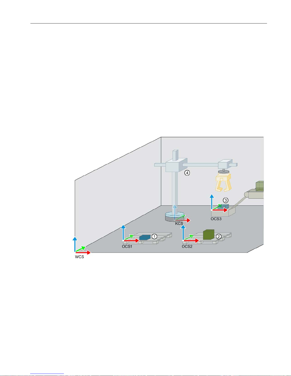
3.3 Task
Different products are transported on a conveyor belt and are to be distributed onto two
different product pallets by a cylindrical robot.
The products first reach the pickup position over a chute at the end of the conveyor belt. At
the pickup position, the products are picked up by the robot and transported to the respective
pallet.
The transport routes should be as follows, depending on the product type:
● Products of product type 1 are stored on pallet 1. On its way to the parking position,
pallet 2 is bypassed with the help of additional intermediate destinations.
● Products of product type 2 are stored on pallet 2. The parking position is approached
directly and without intermediate destinations.
Layout of the work area
①
Pallet 1 (OCS1, for product type 1)
②
Pallet 2 (OCS2, for product type 2)
③
Pickup position (OCS3)
④
Cylindrical robot 3D (KCS)
The different objects and their position in the workspace (WCS) are to be defined by means
of different coordinate systems and frames.
The kinematics coordinate system (KCS) is connected to the kinematics. The position of the
KCS within the kinematics is fixed.
The product pallets and their position, as well as the pickup position are to be defined with
the user-defined object coordinate systems OCS1, OCS2 and OCS3. This means that the
reference for the target position and the target orientation of the kinematics motions to one of
the product pallets or the pickup position is directly specified on the respective OCS.
Page 12
Description
3.4 User program
S7-1500T Getting Started with Kinematics
10 Getting Started, 12/2018, A5E46089528-AA
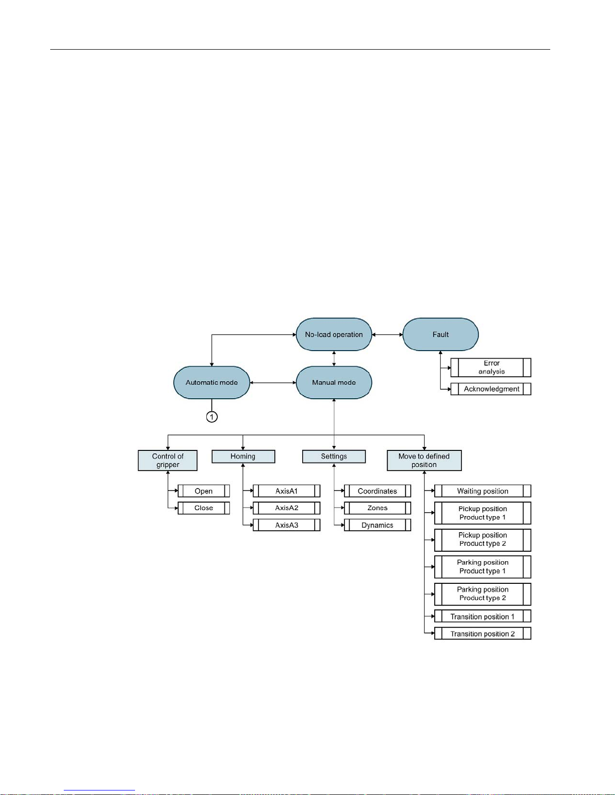
3.4 User program
Overview
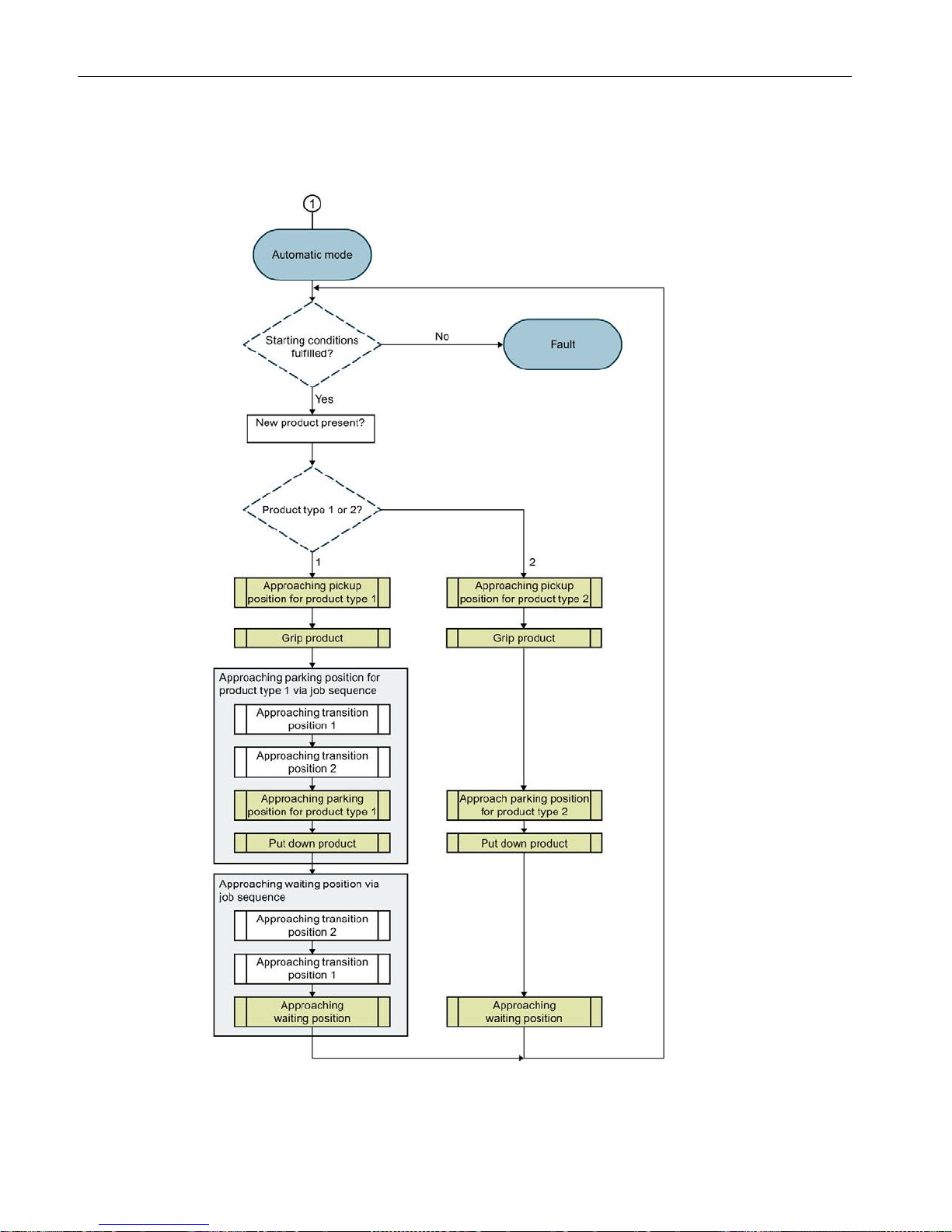
A user program with the following operating modes is implemented for the described task:
● No-load operation (machine in idle state)
● Manual mode
● Automatic mode
● Fault
The user program executes all sequences of the task in automatic mode. The products are
picked up individually in automatic mode and transported to the parking position. The
sequence is repeated until automatic mode is exited.
In manual mode you set the various parameters and use individual functions from automatic
mode.
Page 13

Description
3.4 User program
S7-1500T Getting Started with Kinematics
Getting Started, 12/2018, A5E46089528-AA
11
Manual mode
Before you start automatic mode, make all the necessary settings in manual mode.
● Enable connected axes
● Define home position and home interconnected axes
● Define the coordinates of the defined positions
● Move the kinematics to the waiting position (= start position for automatic mode).
In manual mode, you can also move the kinematics to the defined positions using individual
motion instructions or change the coordinates.
You can test the gripper function by individually opening or closing the gripper (simulation).
The dynamic parameters allow you to observe the behavior of the kinematics motion when
dynamic adaptation is activated and deactivated.
Automatic mode
When automatic mode is called, the following prerequisites for further processing of the
program are first queried.
● Cyclic queries in automatic mode:
– Is the communication to the drive system available?
– Is the drive switched on?
– Are all axes homed?
● Queries during start of automatic mode:
– Is the kinematics in the waiting position?
– Is the job sequence empty?
– Is the size of the job sequence set sufficiently?
When all starting conditions are fulfilled, the program checks whether a new product is
available and what type of product it is. With the information about the product type, the
kinematics moves to the pickup position and picks up the product.
The subsequent motions between the pickup position and one of the two parking positions
are defined as follows, depending on the product type:
●
Product type 1
Two transition positions are defined for the distance between the pickup position and
parking position. Three motion instructions are used to move the kinematics between the
pickup position and the parking position. The three motion instructions are executed via
the job sequence both for moving to the parking position and for returning to the waiting
position.
●
Product type 2
The kinematics moves with a motion between the pickup and the parking position.
Page 14
Description
3.4 User program
S7-1500T Getting Started with Kinematics
12 Getting Started, 12/2018, A5E46089528-AA
The product is parked when the parking position is reached. The kinematics then executes a
motion to the waiting position.
Page 15

Description
3.4 User program
S7-1500T Getting Started with Kinematics
Getting Started, 12/2018, A5E46089528-AA
13
Motion instructions used
The following instructions are used for the respective moves:
Motion
Instructions
Start
Destination
Waiting position Pickup position prod-
uct type 1 / product type 2
"MC_MoveLinearAbsolute" to pickup
position Product type 1 / Product type 2
Pickup position with offset
for product type 1
Parking position on pallet 1
1. "MC_MoveCircularAbsolute" to the
transition position 1
2. "MC_MoveLinearAbsolute" to the
transition position 2
3. "MC_MoveCircularAbsolute" to the
OCS1
Pickup position with offset
for product type 2
Parking position on pallet 2 "MC_MoveCircularAbsolute" to the
OCS2
Parking position on pallet 1 Waiting position
1. "MC_MoveCircularAbsolute" to the
transition position 2
2. "MC_MoveLinearAbsolute" to the
transition position 1
3. "MC_MoveCircularAbsolute" to the
waiting position
Parking position on pallet 2 Waiting position "MC_MoveCircularAbsolute" to the
waiting position
Definition of the circular path ("CircMode") for the instructions "MC_MoveCircularAbsolute"
With the "CircMode" parameter, you specify the definition of the circular path. In the example
project, the default setting "CircMode" = "0" is used for all circular motions and the circular
path is calculated using the start, intermediate and end points. With the auxiliary point of the
circular path ("AuxPoint"), you specify a point on the circular path via which the end point is
to be approached.
The function block "ModeAutomatic" shows an option for calculating the auxiliary points of
the circular path. The auxiliary points of the circular path are determined from the distance
between the start and end position and are thus in the middle of the distance. The
intermediate point is therefore consistent in each case with the specified start and end
points.
Page 16
Description
3.5 Coordinate systems and positions
S7-1500T Getting Started with Kinematics
14 Getting Started, 12/2018, A5E46089528-AA
3.5 Coordinate systems and positions
Kinematics and object coordinates
The values for the kinematics and object coordinates are entered in the Configuration of the
kinematics technology object (Page 23).
KCS
(Kinematics)
OCS1
(Pallet 1)
OCS2
(Pallet 2)
OCS3
(Pickup position at
the chute)
Position x
2000 mm
1000 mm
3000 mm
3500 mm
Position y
3000 mm 1000 mm 1000 mm 3000 mm
Position z
0 mm
100 mm
100 mm
300 mm
Positions and offsets
The values for the positions and offsets are entered via the HMI tags in the watch table
"HMI-Monitor (Page 59)".
Transition position 1
Transition position 2
Position x
3000 mm 2000 mm
Position y
2000 mm
2000 mm
Position z
1800 mm
1800 mm
Offset for waiting position
Offset for product type 1
Offset for product type 2
Position x
0 mm
0 mm
0 mm
Position y
0 mm
0 mm
0 mm
Position z
1000 mm
100 mm
200 mm
Home position
The home position for the interconnected axes can be entered using the corresponding tags
in the watch table "HMI-Monitor (Page 59)".
● Axis AxisA1: 10
● Axis AxisA2: 1
● Axis AxisA3: 1000
Page 17

Description
3.6 Program blocks
S7-1500T Getting Started with Kinematics
Getting Started, 12/2018, A5E46089528-AA
15
3.6 Program blocks
Function blocks
Function block
Function
Instance data block
"CtrlSingleAxis" Control of axes (ena-
ble/disable, reset, homing)
"InstAxisA1"
"InstAxisA2"
"InstAxisA3"
"ModeManual" Manual mode "InstModeManual"
"ModeAutomatic"
Automatic mode
"InstModeAutomatic"
"CtrlGripper" Gripper control (opening,
closing)
"InstGripper"
Functions
Function block
Function
Application
"Compare3D" Function for comparing posi-
tions
Function block "ModeAutomatic"
Query whether gripper is in the waiting
position
"DistanceXYHalf" Function for length calcula-
tion according to Pythagoras
Function block "ModeAutomatic"
Calculation of the respective auxiliary
point of the circular path for the instruc-
tion "MC_MoveCircularAbsolute".
Global data blocks
Data block
Function
Application
"HMI" Global data block for the
PLC data type "typeUserInterface"
Control of technology objects
and display of status values
in the watch table "HMI-
Monitor"
Function blocks "ModeManual"
and "ModeAutomatic"
Page 18
Description
3.7 PLC tags
S7-1500T Getting Started with Kinematics
16 Getting Started, 12/2018, A5E46089528-AA
3.7 PLC tags
User constants
Define the following global user constants under PLC tags:
Name
Data type
Val
ue
Description
OPERATING_MODE_AUTO
UInt 3 Automatic mode
OPERATING_MODE_MANU
AL
UInt 2 Manual mode
OPERATING_MODE_IDLE
UInt 0 No-load operating mode
OPERATING_MODE_ERROR UInt 1 Fault operating mode
WCS
DInt
0
Specification of the respective reference system
of the specified target position and target orientation
OCS1
DInt 1 OCS2
DInt
2
OCS3
DInt
3
3.8 PLC data types
Overview
For the simple and uniform declaration of tags, add the following PLC data types:
Name
Description
typeAuxPosition
Specification of positions without orientation (x, y, z)
typeExecute
Summary of the parameters for the start of the motion instructions to the defined positions
typePosition
Specification of positions with orientation (x, y, z, A)
typePositionState
Summary of the parameters for the display of reached positions per sequence (0 = position not
reached, 1 = position reached)
typeSystemState
Summary of the parameters for the status display of the axes and the drive
typeUserInterface
Summary of the tags for the HMI
typeAuxPosition
Name
Data type
Description
auxPosition Array[1..3] of
LReal
Define the position without orientation (x, y, z)
Page 19

Description
3.8 PLC data types
S7-1500T Getting Started with Kinematics
Getting Started, 12/2018, A5E46089528-AA
17
typeExecute
Name
Data type
Description
waitingPos
Bool
Move to waiting position
pickupPos Bool Move to pickup position
destination1Pos
Bool
Move to the parking position for product type 1
destination2Pos
Bool
Move to the parking position for product type 2
transition1Pos
Bool
Move to the transition position 1
transition2Pos
Bool
Move to the transition position 2
typePosition
Name
Data type
Description
position Array[1..4] of
LReal
Defining position with orientation (x, y, z, A)
typePositionState
Name
Data type
Description
waitingPos
Bool
Waiting position
pickupPos
Bool
Pickup position
destination1Pos
Bool
Parking position for product type 1
destination2Pos
Bool
Parking position for product type 2
transition1Pos
Bool
Transition position 1
transition2Pos
Bool
Transition position 2
typeSystemState
Name
Data type
Description
communicationOK
Bool
Communication with the drive system is available
driveInOperation
Bool
Drive system in operation
homingDone
Bool
Encoder adjustment completed
Page 20

Description
3.8 PLC data types
S7-1500T Getting Started with Kinematics
18 Getting Started, 12/2018, A5E46089528-AA
typeUserInterface
Name
Data type
Description
waitingPosOffset
"typePosition"
Offset for the waiting position
product1Offset "typePosition" Offset for products of product type 1
product2Offset
"typePosition"
Offset for products of product type 2
transitionPos1
"typePosition"
Transition position 1 between conveyor belt and parking position 1
transitionPos2
"typePosition"
Transition position 2 between conveyor belt and parking position 1
productType UInt Enter product type
• 0 = No product / Product type unknown
• 1 = Product type 1
• 2 = Product type 2
operatingMode UInt Selecting the operating state
• 0 = Starting
• 1 = Fault
• 2 = Manual mode
• 3 = Automatic mode
• 4 = Reserved
enableAxes
Bool
Enable axes
executeMoveTo
"typeExecute"
Start motion instructions to the defined positions
interruptMove
Bool
Interrupt current motion
continueMove
Bool
Continue a motion stopped with "interruptMove"
acknowledge
Bool
Acknowledge error
gripper Bool Controlling the gripper
• 1 = Closing
• 0 = Opening
gripperState Bool Status indicator of gripper
• 0 = Open
• 1 = Closed
posState "typePosi-
tionState"
Status display of reached positions per sequence
startChecks "typeSystemSta-
tus"
Axis and drive status display
motionState UInt Status display of motion
• 0 = Inactive
• 1 = Fault
• 2 = Active
• 3 = Reserved
setReferenceAxisA1
Bool
Homing axis "AxisA1"
setReferenceAxisA2
Bool
Homing axis "AxisA2"
setReferenceAxisA3
Bool
Homing axis "AxisA3"
Page 21

Description
3.8 PLC data types
S7-1500T Getting Started with Kinematics
Getting Started, 12/2018, A5E46089528-AA
19
Page 22

S7-1500T Getting Started with Kinematics
20 Getting Started, 12/2018, A5E46089528-AA
4
Adding a controller
To edit the example from the Getting Started, create a SIMATIC S7-1500T controller (as of
firmware version 2.5) in the project.
Page 23

S7-1500T Getting Started with Kinematics
21 Getting Started, 12/2018, A5E46089528-AA
5
5.1 Adding a kinematics technology object
Requirement
To connect the kinematics, create the following positioning axes:
Name
Axis type
Modulo
AxisA1
Virtual axis,
Rotary
• Enable modulo
• Modulo start value: -180°
• Modulo length: 360°
AxisA2
Virtual axis,
Linear
–
AxisA3
Virtual axis,
Linear
–
Page 24

Adding and configuring technology objects
5.1 Adding a kinematics technology object
S7-1500T Getting Started with Kinematics
22 Getting Started, 12/2018, A5E46089528-AA
Procedure
To add a kinematics technology object, follow these steps:
1. Open the CPU's folder in the project navigator.
2. Open the "Technology Objects" folder.
3. Double-click "Add new object".
The "Add new object" dialog opens.
4. Select "TO_Kinematics".
5. Enter the name "CylindricalRobot" in the "Name" entry field.
6. Select the "Add new and open" check box.
7. Click "OK".
Page 25

Adding and configuring technology objects
5.2 Configuring the kinematics technology object
S7-1500T Getting Started with Kinematics
Getting Started, 12/2018, A5E46089528-AA
23
5.2 Configuring the kinematics technology object
Basic parameters
Configure the basic properties of the kinematics technology object in the "Basic Parameters"
configuration window.
1. Select the Kinematics type "Cylindrical robot 3D" from the drop-down list.
2. In the drop-down list, select the desired units of measure for the position, velocity, angle
and angular velocity of the kinematics.
Interconnections
Configure the axes of kinematics in the "Interconnections" configuration window.
1. Interconnect the kinematics axes as follows:
– Kinematics axis A1: "AxisA1"
– Kinematics axis A2: "AxisA2"
– Kinematics axis A3: "AxisA3"
Geometry
Configure the geometric parameters of kinematics in the "Geometry" configuration window.
1. Enter the transformation parameters of the kinematics in these fields:
– Length L1: 2000 mm
– Length L2: 400 mm
– Flange length LF: 200 mm
2. In these fields, define the scaling in which the kinematics is displayed in the kinematics
trace:
– z minimum: 0 mm
– z maximum: 3000 mm
– A3 maximum: 3500 mm
Dynamics
In the example project, the default values are used for the dynamics, the dynamics limits and
the dynamic adaptation of the kinematics motion.
If you want to set certain default values for the Kinematics motion, configure them in the
"Dynamics" configuration window.
When dynamic adaptation is active, a velocity profile is calculated for the entire motion which
takes into account the dynamic limits of the axes and the kinematics. In this example project,
the default values for the dynamic limits of the connected axes are used. If you want to set
certain default values for the dynamic limits of the interconnected axes, configure them
under "Technology object > Configuration > Extended parameters > Limits > Dynamic limits".
Page 26

Adding and configuring technology objects
5.2 Configuring the kinematics technology object
S7-1500T Getting Started with Kinematics
24 Getting Started, 12/2018, A5E46089528-AA
Kinematics coordinate system
In the "Kinematics coordinate system" configuration window, configure the KCS frame and
therefore the position of the kinematics coordinate system (KCS) in the world coordinate
system (WCS).
Enter the values for the position of the kinematic coordinate system (Page 14).
Object coordinate systems
In the "Object coordinate system" configuration window, configure the OCS frames and
therefore the position of the object coordinate systems (OCS) in the world coordinate system
(WCS).
In the drop-down list, select the object coordinate systems "OCS1" to "OCS3" one after the
other and enter Values for the position of the respective object coordinate system (Page 14).
Page 27

S7-1500T Getting Started with Kinematics
25 Getting Started, 12/2018, A5E46089528-AA
6
Add user constants
Insert all required user constants in the default tag table.
A list can be found in the section PLC tags (Page 16).
Adding data types
1. Add all required data types:
– typeAuxPosition
– typeExecute
– typePosition
– typePositionState
– typeSystemState
– typeUserInterface
2. Enter the required tags and data types in the declaration tables of the data types.
A list can be found in the section PLC data types (Page 16).
Page 28

S7-1500T Getting Started with Kinematics
26 Getting Started, 12/2018, A5E46089528-AA
7
For the user interface parameters, add a new data block with the name "HMI" of the type
"typeUserInterface".
The data block "HMI" is created based on the PLC data type "typeUserInterface" (Page 16).
Page 29

S7-1500T Getting Started with Kinematics
27 Getting Started, 12/2018, A5E46089528-AA
8
8.1 Prepare function block
Prepare program block
1. Add the function block "ModeManual" (LAD).
2. Add the instance data block "InstManual".
Parameters in the function block "ModeManual"
Create the following parameters in the "ModeManual" function block.
Name
Data type
Default value
Description
InOut
axesGroup
TO_Kinematics
–
Reference to the technology object
hmi
"typeUserInterface"
–
User interface parameters (control, status query)
Static
statInstMoveLinAbs MC_MOVELINEARAB
SOLUTE
– Instances of the individual motion control instruc-
tions (see data type) for the kinematics process
statInstReset
MC_RESET
–
statInstGroupInterrupt MC_GROUPINTERRU
PT
–
statInstGroupContinue MC_GROUPCONTIN
UE
–
Temp
tempTargetPos typePosition – Absolute target coordi-
nate from the executed
motion instruction
Using this temporary
local data, pass the
values from the respective instruction to the
motion instruction.
tempCoordSystem DInt – Reference system of the
specified target position
and target orientation
tempDone Bool – The value for the completed motion control instruc-
tion "MC_MoveLinearAbsolute" is passed via this
tag to the query of the position reached.
Page 30

Create program for manual mode
8.2 Move kinematics to defined position
S7-1500T Getting Started with Kinematics
28 Getting Started, 12/2018, A5E46089528-AA
8.2 Move kinematics to defined position
Requirements
The following requirements apply to executing the program in manual mode:
● All interconnected axes are switched on and homed.
● At the time of calling a motion instruction in manual mode:
– No motion control instruction "MC_GroupInterrupt" is active.
– If no further motion instruction is active.
– No further motion instruction is activated.
Page 31

Create program for manual mode
8.2 Move kinematics to defined position
S7-1500T Getting Started with Kinematics
Getting Started, 12/2018, A5E46089528-AA
29
Start motion instruction
1. The motion instructions are started individually in manual mode. For each component of
"hmi.executeMoveTo", insert a normally open contact in parallel.
2. The respective target coordinate ("tempTargetPos.position") and the respective reference
system ("tempCoordSystem") are transferred to the motion instruction via the instruction
"Move value" (MOVE).
Page 32

Create program for manual mode
8.2 Move kinematics to defined position
S7-1500T Getting Started with Kinematics
30 Getting Started, 12/2018, A5E46089528-AA
3. In manual mode, the kinematics is positioned exclusively with a linear motion. Insert a
motion control instruction "MC_MoveLinearAbsolute".
4. To use the completed job signal to display the reached position, assign the tag
"tempDone" to the output parameter "Done".
Page 33

Create program for manual mode
8.2 Move kinematics to defined position
S7-1500T Getting Started with Kinematics
Getting Started, 12/2018, A5E46089528-AA
31
Display of the position reached
1. Insert a new network.
2. Insert an NO contact for the tag "tempDone".
3. Insert all components of the parameter "hmi.executeMoveTo" in parallel.
4. To output the status of the position reached, add the respective component of the
parameter "hmi.posState".
Page 34

Create program for manual mode
8.2 Move kinematics to defined position
S7-1500T Getting Started with Kinematics
32 Getting Started, 12/2018, A5E46089528-AA
Interrupt / continue motion execution
1. Insert a new network.
2. To interrupt a motion execution, insert the motion control instruction "MC_GroupInterrupt".
3. To continue a motion execution, insert the motion control instruction
"MC_GroupContinue".
Acknowledge error
1. Insert a new network.
2. To reset all technology alarms and restart the interconnected kinematic axes, insert a
motion control instruction "MC_Reset".
Page 35

Create program for manual mode
8.2 Move kinematics to defined position
S7-1500T Getting Started with Kinematics
Getting Started, 12/2018, A5E46089528-AA
33
Evaluating errors
1. Insert a new network.
2. Insert NO contacts for all "Error" parameters of the motion control instructions from the
function block "ModeManual" in parallel.
3. As long as the signal state of all "Error" parameters is "0" (no error), manual mode is
active and the parameter "hmi.operatingMode" has the value "2". If an error occurs, the
user program switches to Fault operating state. The value of the parameter
"hmi.operatingMode" changes to "1" in the case of an error.
To transfer the respective value to the "hmi.operatingMode" parameter, use the
instruction "Move value" (MOVE).
Page 36

Create program for manual mode
8.3 Controlling the axes
S7-1500T Getting Started with Kinematics
34 Getting Started, 12/2018, A5E46089528-AA
8.3 Controlling the axes
Creating blocks
1. Add a new function block with the name "CtrlSingleAxis" (SCL).
2. Add the following instance data blocks:
– "InstAxisA1"
– "InstAxisA2"
– "InstAxisA3"
Parameters in the CtrlSingleAxis function block
Create the following parameters in the "CtrlSingleAxis" function block.
Name
Data type
Default
value
Comment
Input
axis TO_PositioningAxis – Reference to the technology object
cmdPowerOn
Bool
False
Enable (1) or disable (0) axis using MC_Power
pwrOffMode
Int 0 "StopMode" for "MC_Power"
cmdAcknErr
Bool
False
Run "MC_Reset"
cmdHome
Bool
False
Run "MC_Home"
homePosition
LReal
0.0
Home position for "MC_Home"
operatingMode Int 0 Operating mode
0 = Starting
1 = Fault
2 = Manual mode
3 = Automatic mode
Output
axisActualPos LReal 0.0 Current object position (from the technology object data
block)
summaryError
Bool
False
Error on the axis or in the motion control function
systemState
"typeSystemStatus"
–
Axis and drive status display
Static
statMcPower
MC_POWER
–
Instances of the individual motion control instructions (see
data type) for enabling, resetting and homing the interconnected axes
statMcReset
MC_RESET
–
statMcHome
MC_HOME
–
statPowerErr Bool False Error in the motion control function
statResetErr
Bool
False
statHomeErr
Bool
False
Page 37

Create program for manual mode
8.3 Controlling the axes
S7-1500T Getting Started with Kinematics
Getting Started, 12/2018, A5E46089528-AA
35
Procedure
1. Add the parameters for controlling the axes.
2. Summarize all parameters for error output of the axis control instructions in the
"summaryError" parameter.
3. Assign the corresponding tags from the technology data block to the following output
parameters:
– Current position of the axis technology object
– Communication with the drive system is available
– Drive systems switched on
– Axis homed
Page 38

Create program for manual mode
8.4 Control of gripper
S7-1500T Getting Started with Kinematics
36 Getting Started, 12/2018, A5E46089528-AA
8.4 Control of gripper
Creating blocks
1. Add the function block "CtrlGripper" (LAD).
2. Add the instance data block "InstGripper".
Parameters in the function block "CtrlGripper"
Create the following parameters in the "CtrlGripper" function block.
Name
Data type
Default
value
Comment
Input
close Bool False Control of gripper
• 0 = Opening
• 1 = Closing
time
Time
t#1000 ms
Time for the status change (open ↔ close)
Output
state Bool False Gripper status
• 0 = Open
• 1 = Closed
Static
statInstTime
TP_TIME
–
Instance of the "Create pulse" (TP_TIME) instruction
statPuls
Bool
False
Status change transfer
statClosePos
Bool
False
Edge bit memory "close" (positive signal edge)
statCloseNeg
Bool
False
Edge bit memory "close" (negative signal edge)
statPulsNeg
Bool
False
Edge bit memory "statPuls"
Page 39

Create program for manual mode
8.4 Control of gripper
S7-1500T Getting Started with Kinematics
Getting Started, 12/2018, A5E46089528-AA
37
Procedure
1. For edge detection of the signal at the "close" input, add the following instructions in
network 1:
– Query positive signal edge with edge bit memory "statClosePos"
– Query negative signal edge with edge bit memory "statCloseNeg"
2. To open or close the gripper, the signal at the "close" input should remain unchanged for
a specified time. For this purpose, add a "Generate a pulse" (TP_TIME) instruction.
When an edge change occurs at the "close" input, the specified time period PT expires. If
the specified period has expired and no new edge change has been detected at the
"close" input, the "statPuls" output is set.
3. Create a new network 2 for the "Close gripper" operation.
4. To scan the signals at the "close" input and at the "statPuls" output, use an NO contact
for each.
5. For output of the "state" parameter with a "1", insert the "Set output" instruction.
6. Create a new network 3 for the "Open gripper" operation.
7. Use an NC contact to query the signal at the "close" input.
8. Insert an NO contact for the signal at the "statPuls" output.
9. For output of the "state" parameter with a "0", insert the "Reset output" instruction.
Page 40

S7-1500T Getting Started with Kinematics
38 Getting Started, 12/2018, A5E46089528-AA
9
9.1 Prepare function block
Adding blocks
1. Add a new function block with the name "ModeAutomatic" (SCL).
2. Add a new instance data block with the name "InstAutomatic".
Parameters in the function block "ModeAutomatic"
Create the following parameters in the "ModeAutomatic" function block.
Name
Data type
Default
value
Comment
Output
errorID
Int 0 Error ID (0 = no error, < 0 see constants)
InOut
axesGroup
TO_Kinematics
–
Reference to the technology object
hmi
typeUserInterface
–
Static
statStateAuto Int #STATE_-
CHECK
Program status in automatic mode (see constants)
statMovPickup
Bool
False
Motion to pickup position
Tags for starting the motion
instructions to the defined
positions
statMovDest1
Bool
False
Motion to parking position 1
statMovDest2
Bool
False
Motion to parking position 2
statMovWait
Bool
False
Motion to waiting position
statInstMov-
eToPickupPos
MC_MOVELINEARAB
SOLUTE
– Move linear motion to
pickup position
Instances of the individual
motion control instructions
(see data type) for the kinematics process
statInstMoveToTransi-
tionCirc
MC_MOVECIRCULAR
ABSOLUTE
– Circular motion to the tran-
sition position
statInstMoveToTransi-
tionLin
MC_MOVELINEARAB
SOLUTE
– Linear motion to the transi-
tion position
statInstMoveToDesti-
nation1
MC_MOVECIRCULAR
ABSOLUTE
– Circular motion to the park-
ing position 1
statInstMoveToDesti-
nation2
MC_MOVECIRCULAR
ABSOLUTE
– Circular motion to the park-
ing position 2
statInstMov-
eToWaitPos
MC_MOVECIRCULAR
ABSOLUTE
– Circular motion to the wait-
ing position
staInstGroupInterrupt MC_GROUPINTERRU
PT
– Stopping motion execution
statInstGroupContinue MC_GROUPCONTIN
UE
– Continue motion execution
Page 41

Create a program for automatic mode
9.1 Prepare function block
S7-1500T Getting Started with Kinematics
Getting Started, 12/2018, A5E46089528-AA
39
Name
Data type
Default
value
Comment
statWatchdog
TON_TIME
–
Monitoring of automatic mode
statWatchExpired Bool False Output signal change after wait time elapses
statHoldTime
TON_TIME
–
Wait time at the waiting position
Temp
tempErrorSummary Bool – Error in one of the motion control instructions for the
kinematics process
tempStateWaitingPos typeAuxPosition – Signal output at the end of the wait time at the waiting
position
tempAuxPosition LReal – Transfer of the calculated auxiliary point of the circular
path to the respective motion instruction.
tempLengthhalf LReal – Transfer of the calculated value from the additional length
calculation to the z position of an auxiliary point of the
circular path
Constant
ERR_NONE
Int 0 No error
ERR_STARTPOS
Int
-20
Kinematics is not in waiting position
ERR_PRODUCT_UNS
PECIFIED
Int -21 Entered product type is unknown
ERR_QUEUE_SIZE Int -22 Maximum number of jobs in the job sequence is not suffi-
cient
ERR_QUEUE_CLEAR
Int
-23
Job sequence is not empty
ERR_SYSTEM_CHECK Int -24 Error in communication, in the drive or during homing
ERR_MC_OUTPUT_E
RROR
Int -200 Error in the motion control instruction
STATE_CHECK Int -2 Test conditions for automat-
ic mode
Program status in automatic
mode
STATE_CLEAR Int -1 Program cycle to reset the
Execute inputs
STATE_PRODUCT_W
AIT
Int 0 Product is unknown (wait-
ing for new product)
STATE_PRODUCT_1_
DELIVER
Int 1 Part 1 of the program se-
quence for product type 1 is
active
STATE_PRODUCT_1_
RETURN
Int 2 Part 2 of the program se-
quence for product type 1 is
active
STATE_PRODUCT_2_
DELIVER
Int 3 Program sequence for
product type 2 is active
STATE_RES
Int 4 Not used (reserved)
GRIPPER_CLOSE
Bool
1
Gripper closed
GRIPPER_OPEN
Bool
0
Gripper open
TRANS_DISTANCE
LReal
10
Default values for transition parameters[1]
HOLDTIME
Time
T#1S
Dwell time at the waiting position
WATCHDOGTIME
Time
T#200MS
Time for call check of the automatic mode
Page 42

Create a program for automatic mode
9.2 Querying preconditions
S7-1500T Getting Started with Kinematics
40 Getting Started, 12/2018, A5E46089528-AA
9.2 Querying preconditions
After calling the automatic mode, the program first checks all preconditions for further
processing.
System status
To query the status of the axis and the drive, use the structure components of the formal
parameter "hmi.systemChecks".
Page 43

Create a program for automatic mode
9.2 Querying preconditions
S7-1500T Getting Started with Kinematics
Getting Started, 12/2018, A5E46089528-AA
41
Kinematics starting position
The kinematics starting position at the beginning of the automatic mode is the defined
waiting position ("hmi.waitingPosOffset"). Therefore, the program must check at the start of
automatic mode whether the position of the kinematics corresponds to the default waiting
position.
Add a new function (FC) with the name "Compare3D". In the function "Compare3D" the
program compares positions.
You assign the actual parameters of the positions to be compared in the function block
"ModeAutomatic".
If the condition for the start position is not fulfilled, the corresponding error ("errorID" =
"ERR_STARTPOS") is output and the automatic mode program is no longer processed. In
manual mode, the pending error must be acknowledged and the kinematics moved to the
waiting position. Automatic mode can then be called again.
If the kinematics is in the waiting position, the status display for the waiting position is set to
"True" and the program is processed further.
Page 44

Create a program for automatic mode
9.2 Querying preconditions
S7-1500T Getting Started with Kinematics
42 Getting Started, 12/2018, A5E46089528-AA
Status of the job sequence
To ensure that there is sufficient space in the job sequence for the subsequent motion
instructions, add the following queries to the job sequence:
● Is the job sequence designed for the required number of jobs?
● Is the job sequence empty at the time of the query?
Resetting the Execute parameters
The program should reset all Execute parameters to their default value in the first cycle. This
ensures that all and any Execute parameters that are already switched are reset and can be
edited.
To control the reset, use the constant "STATE_CLEAR" as program status.
Page 45

Create a program for automatic mode
9.3 Product type query
S7-1500T Getting Started with Kinematics
Getting Started, 12/2018, A5E46089528-AA
43
9.3 Product type query
When all preconditions are met and all Execute parameters are reset, the program queries
the required product information.
To do this, use a CASE instruction (multiple branches) in which you query whether a new
product exists and what type of product it is.
9.4 Program section product type 1
Preconditions
To run the program section for product type 1, the result of the product type query must be
"1" and the tag "#statStateAuto" must have the value "#STATE_PRODUCT_1_DELIVER".
Insert the query of the tag tatStateAu"#sto".
If the automatic mode is processed in the first cycle, the tag "#statStateAuto" has the value
"#STATE_CLEAR". In this case, insert the command to reset the Execute parameters of the
motion instructions in program section 1.
Page 46

Create a program for automatic mode
9.4 Program section product type 1
S7-1500T Getting Started with Kinematics
44 Getting Started, 12/2018, A5E46089528-AA
Pick up the product and transport it to the pallet
1. The kinematics moves to the pickup position to pick up the product.
Insert the linear motion instruction ("statInstMoveToPickupPos") and enter the following
parameters:
– To start the motion job, assign the tag "statMovPickUp".
– Enter the position offset for product type 1 as the end position in OCS3.
– To output the signal when the motion instruction has been successfully executed,
assign the "hmi.posState.pickUpPos" parameter.
2. Once the pickup position has been reached, the product is picked up by closing the
gripper.
For this purpose, assign the value "GRIPPER_CLOSE" ("1") to the "hmi.gripper"
parameter.
3. After the product has been picked up, the kinematics moves with a circular motion to the
transition position 1.
The function "DistanceXYHalf" is used to calculate the respective z position of an
auxiliary point of the circular path with a Pythagorean length calculation.
For the length calculation, create a new function (FC) named "DistanceXYHalf".
4. Assign the actual parameters for the length calculation in the function block
"ModeAutomatic".
Page 47

Create a program for automatic mode
9.4 Program section product type 1
S7-1500T Getting Started with Kinematics
Getting Started, 12/2018, A5E46089528-AA
45
5. Insert the calculation for the coordinates (x, y, z) of the auxiliary point of the circular path:
6. Insert the circular motion instruction ("statInstMoveToTransitionCirc") and enter the
following parameters:
– To start the motion job, assign the tag "statMovDest1".
– Assign the previously calculated circular path auxiliary position using the tag
"tempAuxPosition.auxPosition".
– Enter transition position 1 as the end position in the WCS.
– To output the signal when the motion instruction was executed successfully, use the
parameter "hmi.posState.transition1Pos".
7. To move the kinematics to transition position 2, insert the linear motion instruction
("statInstMoveToTransitionLin") and enter the following parameters:
– To start the motion job, assign the tag "statMovDest1".
– Enter transition position 2 as the end position in the WCS.
– Set the motion transition parameter to "2". When the blending distance is reached, the
current motion is blended with the motion of this job. The lower velocity of both jobs is
then used.
– To output the signal when the motion instruction was executed successfully, use the
parameter "hmi.posState.transition2Pos".
Page 48

Create a program for automatic mode
9.4 Program section product type 1
S7-1500T Getting Started with Kinematics
46 Getting Started, 12/2018, A5E46089528-AA
8. The kinematics moves with a circular motion to the parking position on pallet 1.
To calculate the auxiliary point of the circular path, add the function "DistanceXYHalf" and
assign the actual parameters for the length calculation.
Insert the calculation for the coordinates (x, y, z) of the auxiliary point of the circular path:
9. Insert the circular motion instruction ("statInstMoveToDestination1") and enter the
following parameters:
– To start the motion job, assign the tag "statMovDest1".
– Assign the previously calculated circular path auxiliary position using the tag
"tempAuxPosition.auxPosition".
– Enter the offset for product type 1 as end position in OCS1.
– Set the motion transition parameter to "2".
– To output the signal when the motion instruction was executed successfully, use the
parameter "hmi.posState.destination1Pos".
10.Once the parking position has been reached, the product is set down by opening the
gripper.
For this purpose, assign the value "GRIPPER_OPEN" ("0") to the "hmi.gripper"
parameter.
Page 49

Create a program for automatic mode
9.4 Program section product type 1
S7-1500T Getting Started with Kinematics
Getting Started, 12/2018, A5E46089528-AA
47
Return to the waiting position
1. To pick up a new product, the kinematics first moves back to the waiting position. For this
purpose, add the same three motion instructions but in reverse order.
– Circular motion to transition position 2
– Linear motion to transition position 1
Page 50

Create a program for automatic mode
9.4 Program section product type 1
S7-1500T Getting Started with Kinematics
48 Getting Started, 12/2018, A5E46089528-AA
– Circular motion to the waiting position
2. To observe the status of the tag "hmi.posState.waitingPos", use the instruction "Start time
as ON time" ("statHoldTime").
3. At the end of the program section, assign the value "#STATE_CHECK" to the tag
"statStateAuto".
The program continues with the check of the preconditions for the automatic mode.
Page 51

Create a program for automatic mode
9.5 Program section product type 2
S7-1500T Getting Started with Kinematics
Getting Started, 12/2018, A5E46089528-AA
49
9.5 Program section product type 2
Preconditions
To run the program section for product type 2, the result of the product type query must be
"2" and the tag "#statStateAuto" must have the value "#STATE_PRODUCT_2_DELIVER".
Insert the query of the tag "#statStateAuto".
If the automatic mode is processed in the first cycle, the tag "#statStateAuto" has the value
"#STATE_CLEAR". In this case, insert the command to reset the Execute parameters of the
motion instructions in program section 2.
Page 52

Create a program for automatic mode
9.5 Program section product type 2
S7-1500T Getting Started with Kinematics
50 Getting Started, 12/2018, A5E46089528-AA
Pick up the product and transport it to the pallet
1. The kinematics moves to the pickup position to pick up the product.
Insert the linear motion instruction ("statInstMoveToPickupPos") and enter the following
parameters:
– To start the motion job, assign the tag "statMovPickUp".
– Enter the position offset for product type 2 as the end position in OCS3.
– To output the signal when the motion instruction has been successfully executed,
assign the "hmi.posState.pickUpPos" parameter.
2. Once the pickup position has been reached, the product is picked up by closing the
gripper.
For this purpose, assign the value "GRIPPER_CLOSE" ("1") to the "hmi.gripper"
parameter.
3. After the product has been picked up, the kinematics moves with a circular motion to the
parking position on pallet 2.
To calculate the auxiliary point of the circular path, add the function "DistanceXYHalf" and
assign the actual parameters for the length calculation.
4. Insert the calculation for the coordinates (x, y, z) of the auxiliary point of the circular path:
Page 53

Create a program for automatic mode
9.5 Program section product type 2
S7-1500T Getting Started with Kinematics
Getting Started, 12/2018, A5E46089528-AA
51
5. Insert the circular motion instruction ("statInstMoveToTransitionCirc") and enter the
following parameters:
– To start the motion job, assign the tag "statMovDest2".
– Assign the previously calculated circular path auxiliary position using the tag
"tempAuxPosition.auxPosition".
– Enter the offset for product type 2 as the end position in OCS2.
– To output the signal when the motion instruction was executed successfully, use the
parameter "hmi.posState.transition2Pos".
6. Once the parking position has been reached, the product is set down by opening the
gripper.
For this purpose, assign the value "GRIPPER_OPEN" ("0") to the "hmi.gripper"
parameter.
Page 54
Create a program for automatic mode
9.5 Program section product type 2
S7-1500T Getting Started with Kinematics
52 Getting Started, 12/2018, A5E46089528-AA
Return to the waiting position
1. The kinematics returns to the pickup position to pick up a new product.
To calculate the auxiliary point of the circular path, add the function "DistanceXYHalf" and
assign the actual parameters for the length calculation.
2. Insert the calculation for the coordinates (x, y, z) of the auxiliary point of the circular path:
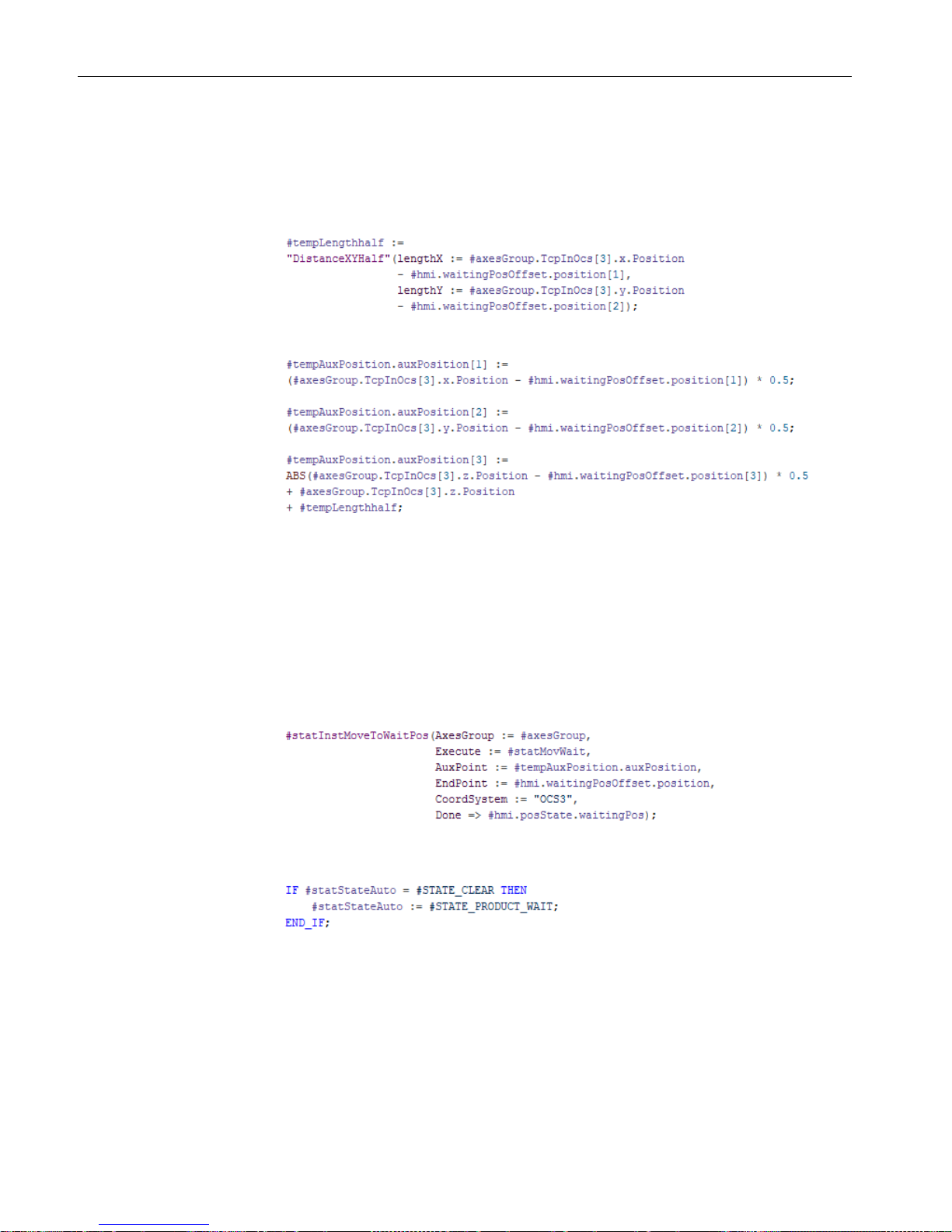
3. To move the kinematics to the waiting position, insert the instruction to the circular motion
"statInstMoveToWaitPos" and enter the following parameters:
– To start the motion job, assign the tag "statMovWait".
– Assign the previously calculated circular path auxiliary position using the tag
"tempAuxPosition.auxPosition".
– Enter the waiting position as end position in OCS3.
– To output the signal when the motion instruction was executed successfully, use the
parameter "hmi.posState.waitingPos".
4. To finish resetting the Execute tags, assign the value "STATE_PRODUCT_WAIT" to the
tag "statStateAuto".
Page 55

Create a program for automatic mode
9.6 Error handling in automatic mode
S7-1500T Getting Started with Kinematics
Getting Started, 12/2018, A5E46089528-AA
53
The program continues with the check of the preconditions for the automatic mode.
5. To observe the status of the tag "hmi.posState.waitingPos", use the instruction "Start time
as ON time" ("statHoldTime").
6. At the end of the program section, assign the value "#STATE_CHECK" to the tag
"statStateAuto".
The program continues with the check of the preconditions for the automatic mode.
9.6 Error handling in automatic mode
Handling errors in motion control instructions
1. If errors occur while processing one of the motion control instructions, they are to be
output via the tag "ErrorID" with the value "-200" ("ERR_MC_OUTPUT_ERROR").
To do this, combine all "Error" parameters of the motion control instructions from the
"ModeAutomatic" function block in the "tempErrorSummary" tag.
2. You can control the behavior in case processing of the automatic mode is canceled by
means of the instruction "Create ON delay".
Page 56

S7-1500T Getting Started with Kinematics
54 Getting Started, 12/2018, A5E46089528-AA
10
Overview
Integrate the previously created part programs and create the main program in the cycle OB
"Main".
Structure of main program
● Control of kinematics in manual mode using the function block "CtrlSingleAxis"
● Query of the status for encoder adjustment, communication and drive using the
parameters from the data block "HMI"
● Control of kinematics in manual mode with the function block "ModeManual"
● Control of kinematics in automatic mode with the function block "ModeAutomatic"
● Gripper control (simulation) using the function block "CtrlGripper".
Page 57

Main organization block Main [OB1]
S7-1500T Getting Started with Kinematics
Getting Started, 12/2018, A5E46089528-AA
55
Controlling the axes
1. Insert the function block "CtrlSingleAxis" for controlling the axes. Use a block instance of
the function block "CtrlSingleAxis" for each axis to do this.
2. Assign the parameters for controlling enabling, homing and restarting to the respective
axis.
3. To enable the axes, exclude no-load mode and fault mode.
4. The axes should only be homed in manual mode.
Network – axis "AxisA1"
You can copy the network of the axis "AxisA1" for the axes "AxisA2" and "AxisA3" and adapt
the following parameters for each:
AxisA1
AxisA2
AxisA3
①
Parameter for homing the
axis
HMI.setReferenceAxi
sA1
HMI.setReferenceAxi
sA2
HMI.setReferenceAxi
sA3
②
Interconnected axis (TO)
AxisA1 AxisA2 AxisA3
③
Instance DB
InstAxisA1 InstAxisA2 InstAxisA3
Page 58

Main organization block Main [OB1]
S7-1500T Getting Started with Kinematics
56 Getting Started, 12/2018, A5E46089528-AA
Status of encoder adjustment, communication and drive
1. Create a new network for each status query.
2. The status feedback is output together for all interconnected axes. Therefore, insert the
parameters of the axes one after the other on a path.
3. To output the signal, assign the respective parameter from the data block "HMI".
Encoder adjustment status
Communication status
Drive status
Page 59

Main organization block Main [OB1]
S7-1500T Getting Started with Kinematics
Getting Started, 12/2018, A5E46089528-AA
57
Control of kinematics in manual mode
1. Insert the function block "ModeManual".
2. To call the block, set the parameter for selecting manual mode.
3. Assign the parameters for the user interface from the data block "HMI".
Controlling the kinematics in automatic mode
1. Insert the function block "ModeAutomatic".
2. To call the block, set the parameter for selecting automatic mode.
3. Assign the parameters for the user interface from the data block "HMI".
Page 60

Main organization block Main [OB1]
S7-1500T Getting Started with Kinematics
58 Getting Started, 12/2018, A5E46089528-AA
Gripper control (simulation)
1. Insert the function block "CtrlGripper" for controlling the gripper.
2. Assign the parameters for controlling the gripper.
Page 61

S7-1500T Getting Started with Kinematics
59 Getting Started, 12/2018, A5E46089528-AA
11
11.1 Preparing the watch table and the kinematics trace
Overview
To test the user program, use the following functionalities in the TIA Portal:
● Kinematics trace
● Watch table
Kinematics trace
In the kinematics trace, you track the current kinematics motion, record it and then play it
back.
The kinematics trace of the kinematics technology object can be found in the project
navigator under "Technology objects > CylindricalRobot > Kinematics trace".
Watch table
Control and monitor the HMI tags using the watch table.
1. Create a new watch table "HMI-Monitor".
2. Insert all parameters from the "HMI" data block into the watch table.
3. Add other relevant parameters for the interconnected axes (
①):
– Home position control
– Display of possible errors
4. Add other relevant parameters for the kinematics technology object (
②):
– Default for velocity and dynamic limitation for the maximum velocity of the path
– Activating/deactivating dynamic limitation
– Velocity override
– Display the current path velocity (setpoint reference)
– Display of possible errors
5. Add other relevant parameters (
③):
– Display of program status in automatic mode
– Display of error ID in automatic mode
Page 62

Testing the user program
11.1 Preparing the watch table and the kinematics trace
S7-1500T Getting Started with Kinematics
60 Getting Started, 12/2018, A5E46089528-AA
6. You can use comment lines to better structure the watch table.
Page 63

Testing the user program
11.2 Perform test
S7-1500T Getting Started with Kinematics
Getting Started, 12/2018, A5E46089528-AA
61
11.2 Perform test
Preparing the simulation
To carry out the test, prepare the simulation as follows:
● Compile the project data and make sure that the compilation process was completed
without errors.
● Start the simulation and load the configuration into the CPU.
● Open the watch table "HMI-Monitor" and the kinematics trace.
Activate the function "Split editor space vertically" so that both items are displayed next to
each other.
Evaluating the path motion
You can save the recordings of the path motions as measurements and load and display
them in the trace. Trace offers you extended evaluation options to analyze path motions in
detail.
In addition, you can create a trace for the velocity and acceleration of the kinematics and the
axes:
● Path velocity ("StatusPath.Velocity")
● Acceleration ("StatusPath.Acceleration")
● Axis velocity ("ActualVelocity")
● Axis acceleration ("ActualAcceleration")
Signal waves from different measurements can be put together in the trace as an overlay
measurement and compared with each other. If you want to use this function, make sure that
the trigger is identical for the recordings that are to be combined.
Page 64

Testing the user program
11.2 Perform test
S7-1500T Getting Started with Kinematics
62 Getting Started, 12/2018, A5E46089528-AA
Prepare kinematics in manual mode
1. Select manual mode by controlling the tag "HMI.operatingMode" with the value "2".
2. Enable the axes using the tag "HMI.enableAxes".
3. Enter the home position (Page 14) for the interconnected axes.
4. Home the axes using "HMI.setReferenceAxisA1", "HMI.setReferenceAxisA2" and
"HMI.setReferenceAxisA3".
5. Enter the control values for the defined positions.
A list of the positions and offsets can be found in the section Coordinate systems and
positions (Page 14).
6. Now you can test the functionalities described below or call automatic mode.
However, before leaving the manual mode, move the kinematics to the waiting position.
This ensures that the condition for positioning the kinematics for starting automatic mode
is fulfilled.
Move kinematics to defined position
1. Move the kinematics to one of the defined positions by controlling one of the
"HMI.executeMoveTo" tags.
2. Check whether the position was reached and whether it is output by the corresponding
status tag.
3. Modify the tag from step 1 back to "0".
Changing position values
1. Change the default position values.
2. Move the kinematics to the new position by controlling the corresponding
"HMI.executeMoveTo" tag.
3. In the kinematics trace, check whether the kinematics moves to the newly configured
position.
4. Check whether the position was reached and whether it is output by the corresponding
status tag.
Opening/closing the gripper
1. Open and close the gripper using the tag "HMI.gripper".
2. Observe whether the state is output via the status tag "HMI".gripperState".
Page 65

Testing the user program
11.2 Perform test
S7-1500T Getting Started with Kinematics
Getting Started, 12/2018, A5E46089528-AA
63
Move kinematics in automatic mode
1. You have already performed the described steps 1 to 6 to prepare the kinematics in
manual mode.
2. Select automatic mode by modifying the tag "HMI.operatingMode" with the value "3".
3. Enter one of the two product types with "HMI".productType".
4. Check whether the following status tags are output correctly:
– Display of the current positions
– The gripper is closed after reaching a pickup position.
– The gripper is opened after reaching a parking position.
5. Change the product type specification with "HMI".productType".
6. Check whether all status tags from step 4 are output correctly.
7. Test the interruption and continuation of a motion using the tags "HMI.interruptMove" and
"HMI.continueMove".
Changing dynamic values
1. Change the velocity defaults for the path:
– Enter the velocity of the path using the "DynamicDefaults.Path.Velocity" parameter.
Due to the activated dynamic adaptation, first enter a velocity that is below the preset
dynamic limits at the interconnected axes.
– Enter a dynamic limitation for the maximum velocity of the path using the
"DynamicLimits.Path.Velocity" parameter. First enter a limit that is above the specified
velocity.
– Check whether the path velocity output via the tag "StatusPath.Velocity" corresponds
to the specified velocity.
2. Use the dynamic adaptation:
– At the Kinematics technology object, enter a velocity that lies above the specified
dynamic limits at the interconnected axes.
– You can observe the behavior through dynamic adaptation in the trace.
3. Deactivate dynamic adaptation with the parameter "DynamicDefaults.DynamicAdaption"
(="0").
4. Dynamic limitation for the maximum velocity of the path
– Use the parameter "DynamicLimits.Path.Velocity" at the kinematics technology object
to enter a dynamic limit that is below the specified velocity of the path.
– Check the limitation of the current path velocity with the tag "StatusPath.Velocity".
– Enter a percentage correction of the velocity specification using the tag
"Override.Velocity".
– Check the limitation of the current path velocity with the tag "StatusPath.Velocity".
Page 66

Testing the user program
11.2 Perform test
S7-1500T Getting Started with Kinematics
64 Getting Started, 12/2018, A5E46089528-AA
Troubleshooting
1. To acknowledge pending errors to the user program, select the manual mode by
modifying the tag "HMI.operatingMode" with the value "2".
2. Acknowledge the error with the tag "HMI.acknowledge".
 Loading...