

Page 1
Page 2

___________________
___________________
___________________
___________________
___________________
___________________
___________________
___________________
___________________
___________________
___________________
___________________
___________________
___________________
___________________
___________________
___________________
SIMATIC
S7-1500
S7-1500R/H redundant system
System Manual
10/2018
A5E41814787
Preface
Documentation guide
1
System overview
2
Application planning
3
Installation
4
Wiring
5
Configuration
6
Basics of program execution
7
Protection
8
Commissioning
9
Display
10
Maintenance
11
Test functions
12
Technical specifications
13
Dimension drawings
A
Accessories/spare parts
B
Safety symbols
C
-AA
Page 3
Siemens AG
Division Digital Factory
Postfach 48 48
90026 NÜRNBERG
GERMANY
A5E41814787-AA
Ⓟ
Copyright © Siemens AG 2018.
All rights reserved
Legal information
Warning notice system
DANGER
indicates that death or severe personal injury will result if proper precautions are not taken.
WARNING
indicates that death or severe personal injury may result if proper precautions are not taken.
CAUTION
indicates that minor personal injury can result if proper precautions are not taken.
NOTICE
indicates that property damage can result if proper precautions are not taken.
Qualified Personnel
personnel qualified
Proper use of Siemens products
WARNING
Siemens products may only be used for the applications described in the catalog and in the relevant technical
ambient conditions must be complied with. The information in the relevant documentation must be observed.
Trademarks
Disclaimer of Liability
This manual contains notices you have to observe in order to ensure your personal safety, as well as to prevent
damage to property. The notices referring to your personal safety are highlighted in the manual by a safety alert
symbol, notices referring only to property damage have no safety alert symbol. These notices shown below are
graded according to the degree of danger.
If more than one degree of danger is present, the warning notice representing the highest degree of danger will
be used. A notice warning of injury to persons with a safety alert symbol may also include a warning relating to
property damage.
The product/system described in this documentation may be operated only by
task in accordance with the relevant documentation, in particular its warning notices and safety instructions.
Qualified personnel are those who, based on their training and experience, are capable of identifying risks and
avoiding potential hazards when working with these products/systems.
Note the following:
documentation. If products and components from other manufacturers are used, these must be recommended
or approved by Siemens. Proper transport, storage, installation, assembly, commissioning, operation and
maintenance are required to ensure that the products operate safely and without any problems. The permissible
All names identified by ® are registered trademarks of Siemens AG. The remaining trademarks in this publication
may be trademarks whose use by third parties for their own purposes could violate the rights of the owner.
We have reviewed the contents of this publication to ensure consistency with the hardware and software
described. Since variance cannot be precluded entirely, we cannot guarantee full consistency. However, the
information in this publication is reviewed regularly and any necessary corrections are included in subsequent
editions.
for the specific
09/2018 Subject to change
Page 4

Preface
Purpose of the documentation
Basic knowledge required
Validity of the documentation
Conventions
Note
A note contains important information on the product described in the
handling of the product or on the section of the documentation to which particular attention
should be paid.
Recycling and disposal
This documentation provides important information on the following aspects of the
S7-1500R/H redundant system:
● An overview of the redundant system
● Configuration and failure scenarios
● How to install, wire and commission the redundant system
● Information on maintenance and fault correction
General knowledge in the field of automation engineering is required to understand this
documentation.
This documentation applies to all products of the SIMATIC S7-1500R/H redundant system.
STEP 7: In this documentation, "STEP 7" is used as a synonym for all versions of the
configuration and programming software "STEP 7 (TIA Portal)".
Please also see the notes indicated as follows:
For environmentally friendly recycling and disposal of your old equipment, contact a certified
electronic waste disposal company and dispose of the equipment according to the applicable
regulations in your country.
documentation, on the
S7-1500R/H redundant system
System Manual, 10/2018, A5E41814787-AA
3
Page 5

Preface
Security information
Siemens Industry Online Support
Product support
Application examples
Services
Forums
mySupport
Siemens provides products and solutions with industrial security functions that support the
secure operation of plants, systems, machines and networks.
In order to protect plants, systems, machines and networks against cyber threats, it is
necessary to implement – and continuously maintain – a holistic, state-of-the-art industrial
security concept. Siemens' products and solutions constitute one element of such a concept.
Customers are responsible for preventing unauthorized access to their plants, systems,
machines and networks. Such systems, machines and components should only be
connected to an enterprise network or the internet if and to the extent such a connection is
necessary and only when appropriate security measures (e.g. firewalls and/or network
segmentation) are in place.
For additional information on industrial security measures that may be implemented, please
visit (https://www.siemens.com/industrialsecurity).
Siemens' products and solutions undergo continuous development to make them more
secure. Siemens strongly recommends that product updates are applied as soon as they are
available and that the latest product versions are used. Use of product versions that are no
longer supported, and failure to apply the latest updates may increase customers' exposure
to cyber threats.
To stay informed about product updates, subscribe to the Siemens Industrial Security RSS
Feed under (https://www.siemens.com/industrialsecurity).
You can find current information on the following topics quickly and easily here:
●
All the information and extensive know-how on your product, technical specifications,
FAQs, certificates, downloads, and manuals.
●
Tools and examples to solve your automation tasks – as well as function blocks,
performance information and videos.
●
Information about Industry Services, Field Services, Technical Support, spare parts and
training offers.
●
For answers and solutions concerning automation technology.
●
Your personal working area in Industry Online Support for messages, support queries,
and configurable documents.
This information is provided by the Siemens Industry Online Support in the Internet
(https://support.industry.siemens.com).
S7-1500R/H redundant system
4 System Manual, 10/2018, A5E41814787-AA
Page 6

Preface
Industry Mall
The Industry Mall is the catalog and order system of Siemens AG for automation and drive
solutions on the basis of Totally Integrated Automation (TIA) and Totally Integrated Power
(TIP).
You can find catalogs for all automation and drive products on the Internet
(https://mall.industry.siemens.com).
S7-1500R/H redundant system
System Manual, 10/2018, A5E41814787-AA
5
Page 7

Table of contents
Preface ................................................................................................................................................... 3
1 Documentation guide ............................................................................................................................ 11
2 System overview ................................................................................................................................... 14
3 Application planning .............................................................................................................................. 49
2.1 What is the S7-1500R/H redundant system? ........................................................................ 14
2.1.1 Areas of application ............................................................................................................... 15
2.1.2 Operating principle of the S7-1500R/H redundant system .................................................... 19
2.1.3 Plant components and automation levels .............................................................................. 25
2.1.4 Scalability ............................................................................................................................... 26
2.1.5 Overview of features .............................................................................................................. 29
2.2 Configuration .......................................................................................................................... 30
2.2.1 Structure of the S7-1500R redundant system ....................................................................... 30
2.2.2 Structure of the S7-1500H redundant system ....................................................................... 31
2.2.3 Components ........................................................................................................................... 33
2.3 S7-1500 R/H-CPUs ................................................................................................................ 35
2.3.1 Overview of the CPU technical specifications ....................................................................... 35
2.3.2 Redundancy ........................................................................................................................... 36
2.3.3 Security .................................................................................................................................. 38
2.3.4 Diagnostics ............................................................................................................................. 39
2.3.5 Trace ...................................................................................................................................... 41
2.4 Communication ...................................................................................................................... 43
2.4.1 System and device IP addresses........................................................................................... 43
2.4.2 Integrated interfaces for communication ................................................................................ 45
2.4.3 HMI devices ........................................................................................................................... 46
2.5 Power supply .......................................................................................................................... 46
2.6 Software ................................................................................................................................. 47
2.6.1 TIA Portal ............................................................................................................................... 47
2.6.2 SINETPLAN ........................................................................................................................... 48
2.6.3 PRONETA .............................................................................................................................. 48
3.1 Requirements ......................................................................................................................... 49
3.2 Restrictions compared to the S7-1500 automation system ................................................... 51
3.3 Configuration versions ........................................................................................................... 54
3.3.1 S7-1500R/H configuration with IO devices in the PROFINET ring ........................................ 55
3.3.2 S7-1500R/H configuration with switches and linear topology ................................................ 57
3.4 Redundancy scenarios .......................................................................................................... 59
3.4.1 Introduction ............................................................................................................................ 59
3.4.2 Failure of the primary CPU .................................................................................................... 60
3.4.3 Failure of the backup CPU ..................................................................................................... 62
3.4.4 Failure of the PROFINET cable in the PROFINET ring ......................................................... 64
3.4.5 Specific redundancy scenarios for S7-1500H ........................................................................ 66
3.4.5.1 Failure of a redundancy connection in S7-1500H.................................................................. 66
3.4.5.2 Failure of both redundancy connections in S7-1500H > 1500 ms apart ............................... 68
3.4.5.3 Failure of both redundancy connections and the PROFINET cable in the PROFINET
ring ......................................................................................................................................... 70
S7-1500R/H redundant system
6 System Manual, 10/2018, A5E41814787-AA
Page 8

Table of contents
4 Installation ............................................................................................................................................ 96
5 Wiring ................................................................................................................................................. 108
3.5 Failure scenarios ..................................................................................................................... 72
3.5.1 Failure of an IO device in the PROFINET ring ....................................................................... 73
3.5.2 Failure of a switch (with line topology) in the PROFINET ring................................................ 75
3.5.3 Specific failure scenarios with S7-1500R ............................................................................... 77
3.5.3.1 Two cable interruptions in the PROFINET ring in S7-1500R > 1500 ms apart ...................... 77
3.5.3.2 Two cable interruptions in the PROFINET ring in S7-1500R within ≤ 1500 ms ..................... 79
3.5.3.3 Failure of the primary CPU when IO devices have failed in the PROFINET ring ................... 81
3.5.4 Specific failure scenarios with S7-1500H ............................................................................... 84
3.5.4.1 Failure of both redundancy connections in S7-1500H ≤ 1500 ms apart ................................ 84
3.5.4.2 Failure of one redundancy connection and the primary CPU in S7-1500H ............................ 86
3.6 Hardware configuration ........................................................................................................... 88
3.7 Use of a system power supply ................................................................................................ 90
3.8 Using HMI devices .................................................................................................................. 92
4.1 Basics...................................................................................................................................... 96
4.2 Installing the mounting rail ...................................................................................................... 98
4.3 Installing a load current supply ............................................................................................. 102
4.4 Installing a system power supply .......................................................................................... 104
4.5 Installing R/H-CPUs .............................................................................................................. 106
5.1 Rules and regulations for operation ...................................................................................... 108
5.2 Operation on grounded infeed .............................................................................................. 110
5.3 Electrical configuration .......................................................................................................... 113
5.4 Wiring rules ........................................................................................................................... 114
5.5 Connecting the supply voltage .............................................................................................. 115
5.6 Connecting system power supply and load current supply .................................................. 117
5.7 Connecting the CPU to the load power supply ..................................................................... 118
5.8 Connecting interfaces for communication with S7-1500R .................................................... 120
5.8.1 Connecting the PROFINET ring to S7-1500 ......................................................................... 120
5.9 Connecting interfaces for communication with S7-1500H .................................................... 123
5.9.1 Connecting redundancy connections (fiber-optic cables) ..................................................... 123
5.9.1.1 Synchronization modules for S7-1500H ............................................................................... 123
5.9.1.2 Selecting fiber-optic cables ................................................................................................... 124
5.9.1.3 Installing fiber-optic cables ................................................................................................... 128
5.9.1.4 Connecting redundancy connections (fiber-optic cables) to S7-1500H ............................... 130
5.9.2 Connecting the PROFINET ring to S7-1500H ...................................................................... 134
S7-1500R/H redundant system
System Manual, 10/2018, A5E41814787-AA
7
Page 9

Table of contents
6 Configuration ....................................................................................................................................... 136
7 Basics of program execution ................................................................................................................ 148
8 Protection ............................................................................................................................................ 168
9 Commissioning .................................................................................................................................... 178
6.1 Configuring the CPU ............................................................................................................ 136
6.2 Configuration procedure ...................................................................................................... 136
6.3 Project tree ........................................................................................................................... 143
6.4 Parameters ........................................................................................................................... 144
6.5 Process images and process image partitions .................................................................... 145
6.5.1 Process image - overview .................................................................................................... 145
6.5.2 Updating process image partitions in the user program ...................................................... 146
7.1 Programming the S7-1500R/H ............................................................................................. 148
7.2 Restrictions .......................................................................................................................... 150
7.3 Events and OBs ................................................................................................................... 153
7.4 Special instructions for S7-1500R/H redundant systems .................................................... 157
7.4.1 Disabling/enabling SYNCUP with the RH_CTRL instruction ............................................... 157
7.4.2 Determining the primary CPU with "RH_GetPrimaryID" ...................................................... 160
7.5 Asynchronous instructions ................................................................................................... 161
8.1 Overview of the protection functions .................................................................................... 168
8.2 Configuring access protection for the CPU .......................................................................... 168
8.3 Using the display to set additional password protection ...................................................... 172
8.4 Using the user program to set additional access protection ................................................ 172
8.5 Know-how protection ........................................................................................................... 173
8.6 Protection by locking the CPU ............................................................................................. 177
9.1 Overview .............................................................................................................................. 178
9.2 Check before powering on for the first time ......................................................................... 179
9.3 Commissioning procedure ................................................................................................... 180
9.3.1 Removing/plugging in SIMATIC memory cards ................................................................... 181
9.3.2 First power-on of the CPUs .................................................................................................. 184
9.3.3 CPU pairing .......................................................................................................................... 184
9.3.4 Redundancy IDs................................................................................................................... 187
9.3.5 Downloading projects to the CPUs ...................................................................................... 192
9.4 Operating and system states ............................................................................................... 197
9.4.1 Overview .............................................................................................................................. 197
9.4.2 STARTUP operating state ................................................................................................... 200
9.4.3 STOP operating state .......................................................................................................... 203
9.4.4 SYNCUP operating state ..................................................................................................... 203
9.4.5 RUN operating states ........................................................................................................... 204
9.4.6 SYNCUP system state ......................................................................................................... 205
9.4.7 System and operating state transitions ................................................................................ 217
9.4.8 Loss of redundancy .............................................................................................................. 226
9.4.9 Displaying and changing the system state .......................................................................... 229
S7-1500R/H redundant system
8 System Manual, 10/2018, A5E41814787-AA
Page 10

Table of contents
10 Display ................................................................................................................................................ 248
11 Maintenance ....................................................................................................................................... 257
12 Test functions ..................................................................................................................................... 282
13 Technical specifications ...................................................................................................................... 289
9.5 CPU memory reset ............................................................................................................... 231
9.5.1 Automatic memory reset ....................................................................................................... 232
9.5.2 Manual memory reset ........................................................................................................... 233
9.6 Backing up and restoring the CPU configuration .................................................................. 234
9.7 Time synchronization ............................................................................................................ 239
9.7.1 Example: Configuring the NTP server .................................................................................. 240
9.8 Identification and maintenance data ..................................................................................... 241
9.8.1 Reading out and entering I&M data ...................................................................................... 241
9.8.2 Record structure for I&M data ............................................................................................... 243
9.8.3 Example: Read out firmware version of the CPU with Get_IM_Data ................................... 245
10.1 CPU display .......................................................................................................................... 248
11.1 Replacing components of the S7-1500R/H redundant system ............................................ 257
11.1.1 Checking before replacing components ............................................................................... 257
11.1.2 Replacing defective R/H-CPUs ............................................................................................. 260
11.1.3 Replacing defective redundancy connections ...................................................................... 261
11.1.3.1 Replacing two defective PROFINET cables with S7-1500R ................................................ 262
11.1.3.2 Replacing a defective redundancy connection with S7-1500H ............................................ 263
11.1.3.3 Replacing defective synchronization module with S7-1500H ............................................... 263
11.1.3.4 Replacing both defective redundancy connections with S7-1500H ..................................... 264
11.1.4 Replacing defective PROFINET cables ................................................................................ 265
11.1.5 Replacing a defective SIMATIC memory card ...................................................................... 266
11.1.6 Replacing a defective system power supply PS or load power supply PM .......................... 267
11.1.7 Replacing defective IO devices/switches.............................................................................. 268
11.2 Replacing the front cover ...................................................................................................... 269
11.3 Replacing the coding element at the power connector of the system power supply and
load current supply ................................................................................................................ 270
11.4 Firmware update ................................................................................................................... 272
11.5 Resetting CPUs to factory settings ....................................................................................... 277
11.6 Maintenance and repair ........................................................................................................ 281
12.1 Test functions ........................................................................................................................ 282
12.2 Reading out/saving service data ........................................................................................... 287
13.1 Standards and Approvals ..................................................................................................... 290
13.2 Electromagnetic compatibility ............................................................................................... 296
13.3 Shipping and storage conditions ........................................................................................... 298
13.4 Mechanical and climatic ambient conditions ........................................................................ 299
13.5 Information on insulation tests, protection class, degree of protection and rated voltage .... 300
13.6 Use of S7-1500R/H in Zone 2 hazardous area .................................................................... 301
S7-1500R/H redundant system
System Manual, 10/2018, A5E41814787-AA
9
Page 11

Table of contents
A Dimension drawings ............................................................................................................................. 302
B Accessories/spare parts ....................................................................................................................... 305
C Safety symbols .................................................................................................................................... 307
Glossary .............................................................................................................................................. 310
Index ................................................................................................................................................... 323
C.1 Safety-related symbols for devices without Ex protection ................................................... 307
C.2 Safety-related symbols for devices with Ex protection ........................................................ 308
S7-1500R/H redundant system
10 System Manual, 10/2018, A5E41814787-AA
Page 12
1
Basic information
Device information
General information
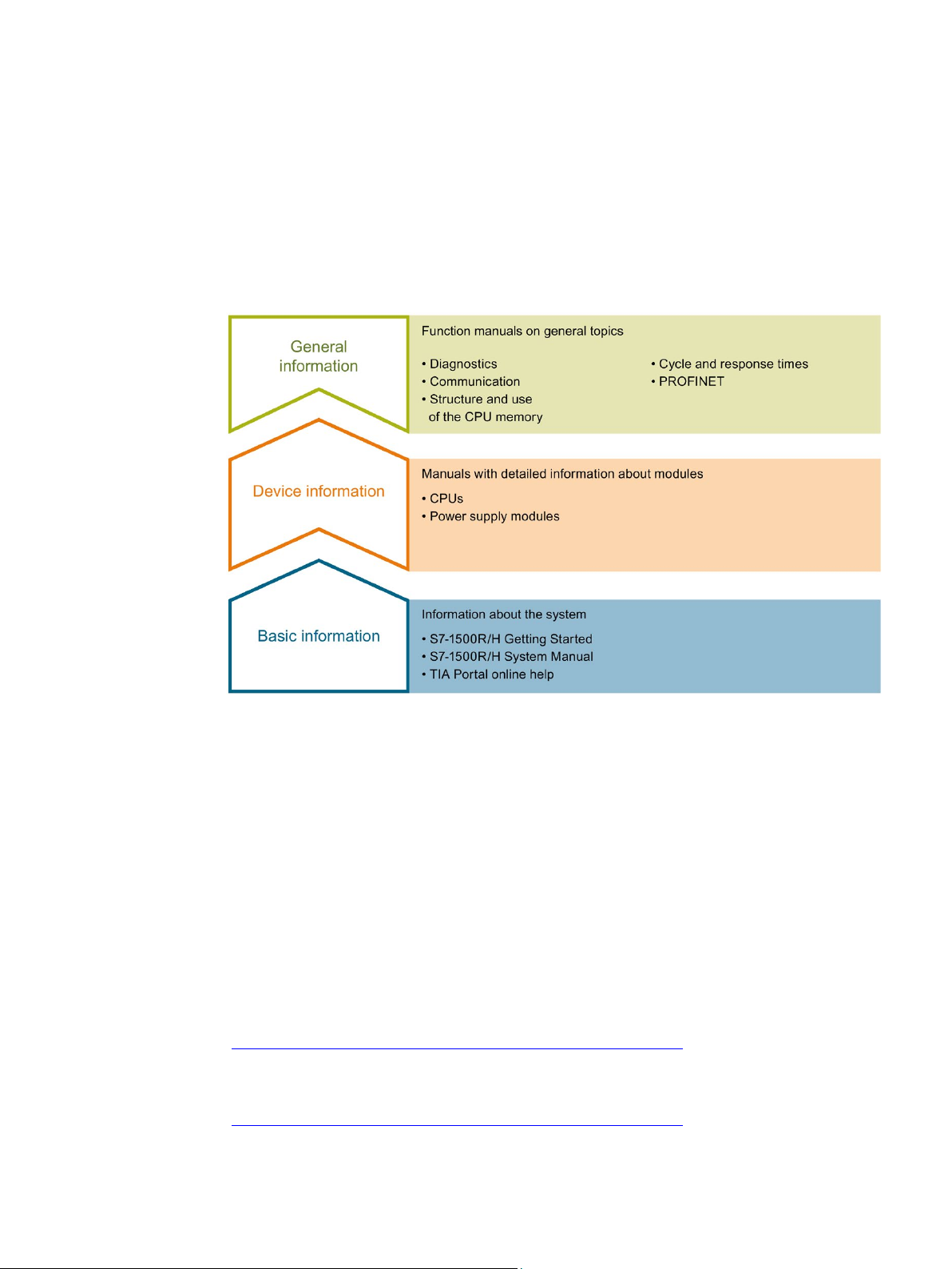
The documentation for the redundant S7-1500R/H system is divided into three areas.
This division enables you to access the specific content you require.
Figure 1-1 S7-1500R/H guide
The System Manual and Getting Started describe in detail the configuration, installation,
wiring and commissioning of the redundant S7-1500R/H system. The STEP 7 online help
supports you in the configuration and programming.
Product manuals contain a compact description of the module-specific information, such as
properties, wiring diagrams, characteristics and technical specifications.
The function manuals contain detailed descriptions on general topics regarding the
redundant S7-1500R/H system, e.g. diagnostics, communication.
You can download the documentation free of charge from the Internet
(https://support.industry.siemens.com/cs/ww/en/view/109742691).
Changes and supplements to the manuals are documented in a Product Information.
You can download the product information free of charge from the Internet
(https://support.industry.siemens.com/cs/ww/en/view/109742691).
S7-1500R/H redundant system
System Manual, 10/2018, A5E41814787-AA
11
Page 13

Documentation guide
S7-1500/ET 200MP Manual Collection
SIMATIC S7-1500 comparison list for programming languages
"mySupport"
"mySupport" - Documentation
"mySupport" - CAx data
The S7-1500/ET 200MP Manual Collection contains the complete documentation on the
redundant S7-1500R/H system gathered together in one file.
You can find the Manual Collection on the Internet
(https://support.industry.siemens.com/cs/ww/en/view/86140384).
The comparison list contains an overview of which instructions and functions you can use for
which controller families.
You can find the comparison list on the Internet
(https://support.industry.siemens.com/cs/ww/en/view/86630375).
With "mySupport", your personal workspace, you make the best out of your Industry Online
Support.
In "mySupport", you can save filters, favorites and tags, request CAx data and compile your
personal library in the Documentation area. In addition, your data is already filled out in
support requests and you can get an overview of your current requests at any time.
You must register once to use the full functionality of "mySupport".
You can find "mySupport" on the Internet (https://support.industry.siemens.com/My/ww/en/).
In the Documentation area in "mySupport" you can combine entire manuals or only parts of
these to your own manual.
You can export the manual as PDF file or in a format that can be edited later.
You can find "mySupport" - Documentation on the Internet
(https://support.industry.siemens.com/My/ww/en/documentation).
In the CAx data area in "mySupport", you can access the current product data for your CAx
or CAe system.
You configure your own download package with a few clicks.
In doing so you can select:
● Product images, 2D dimension drawings, 3D models, internal circuit diagrams, EPLAN
macro files
● Manuals, characteristics, operating manuals, certificates
● Product master data
You can find "mySupport" - CAx data on the Internet
(https://support.industry.siemens.com/my/ww/en/CAxOnline).
S7-1500R/H redundant system
12 System Manual, 10/2018, A5E41814787-AA
Page 14

Documentation guide
Application examples
PRONETA
SINETPLAN
The application examples support you with various tools and examples for solving your
automation tasks. Solutions are shown in interplay with multiple components in the system separated from the focus on individual products.
You will find the application examples on the Internet
(https://support.industry.siemens.com/sc/ww/en/sc/2054).
With SIEMENS PRONETA (PROFINET network analysis), you analyze the PROFINET
network during commissioning. PRONETA features two core functions:
● The topology overview independently scans PROFINET network and all connected
components.
● The IO check is a fast test of the wiring and the module configuration of a system.
You can find SIEMENS PRONETA on the Internet
(https://support.industry.siemens.com/cs/ww/en/view/67460624).
SINETPLAN, the Siemens Network Planner, supports you in planning automation systems
and networks based on PROFINET. The tool facilitates professional and predictive
dimensioning of your PROFINET installation as early as in the planning stage. In addition,
SINETPLAN supports you during network optimization and helps you to exploit network
resources optimally and to plan reserves. This helps to prevent problems in commissioning
or failures during productive operation even in advance of a planned operation. This
increases the availability of the production plant and helps improve operational safety.
The advantages at a glance
● Network optimization thanks to port-specific calculation of the network load
● Increased production availability thanks to online scan and verification of existing systems
● Transparency before commissioning through importing and simulation of existing STEP 7
projects
● Efficiency through securing existing investments in the long term and optimal exploitation
of resources
You can find SINETPLAN on the Internet (https://www.siemens.com/sinetplan).
S7-1500R/H redundant system
System Manual, 10/2018, A5E41814787-AA
13
Page 15
2
2.1
What is the S7-1500R/H redundant system?
S7-1500R/H redundant system
Aims of using redundant automation systems
WARNING
Please note the difference between fault-tolerant and fail-safe systems.
For the S7-1500R/H redundant system, the CPUs are duplicated, in other words redundant.
The two CPUs process the same project data and the same user program in parallel. The
two CPUs are synchronized over two redundancy connections. If one CPU fails, the other
CPU maintains control of the process.
Redundant automation systems are used in practice to achieve greater availability or failsafety.
● Purpose of fault-tolerant systems: to reduce the probability of production downtime by
operating two systems in parallel.
● Purpose of fail-safe systems: to protect life, the environment and capital with safe
shutdown to a secure state.
S7-1500R/H is a fault-tolerant automation system, but not a fail-safe system. The S71500R/H system must not be used to control safety-critical processes.
S7-1500R/H redundant system
14 System Manual, 10/2018, A5E41814787-AA
Page 16

System overview
2.1.1
Areas of application
Objective
Use
2.1 What is the S7-1500R/H redundant system?
The S7-1500R/H redundant system offers a high degree of reliability and system availability.
A redundant configuration of the most important automation components reduces the
probability of production downtimes and the consequences of component errors.
The higher the risks and costs of a production downtime, the more worthwhile the use of a
redundant system. You can compensate for the generally higher investment costs by
avoiding production downtimes.
In redundantly operated systems, failure or malfunction of individual automation components
must not impede the operation of the plant. S7-1500R/H redundant systems are used in the
following areas, for example:
● Tunnels
● Airports (for example baggage conveyors)
● Subways
● Shipbuilding
● Wastewater treatment plants
● High-bay warehouse
S7-1500R/H redundant system
System Manual, 10/2018, A5E41814787-AA
15
Page 17
System overview
Example 1: Avoiding downtimes
Automation task
Feature
Solution
Benefits
2.1 What is the S7-1500R/H redundant system?
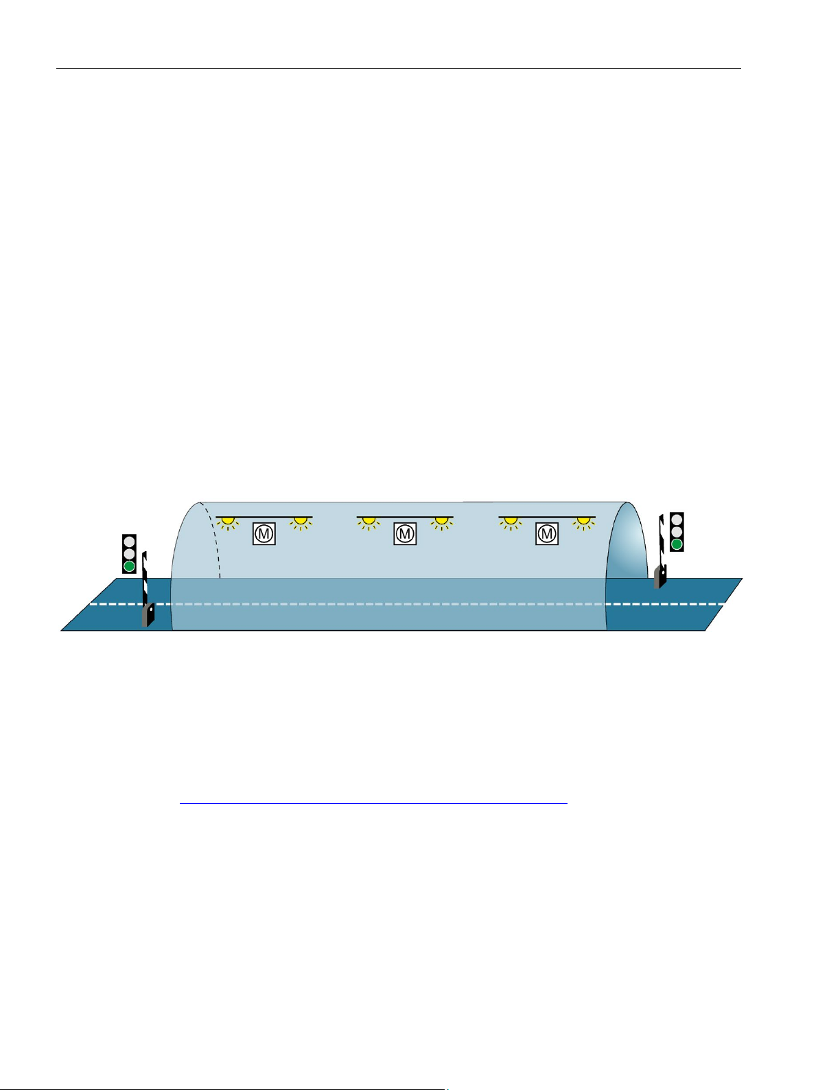
An automation solution is required for a road tunnel to:
● Control the lighting in the tunnel
● Control the ventilation in the tunnel in line with the concentration of pollutants in the tunnel
Uninterrupted operation of the ventilation system is required to keep the concentration of
pollutants below a set level. Constant availability must be ensured for the event that
individual automation components fail, for example because of a fire in the tunnel.
Three fans (M) ventilate the tunnel. The automation solution controls the fan speeds in line
with the measured pollutant concentration. Three sensors in the tunnel measure the pollutant
levels in the air. The S7-1500H redundant system with two redundant CPUs is used to
ensure fan availability.
As well as controlling the fans, the S7-1500H redundant system also controls the illumination
and the traffic lights.
Figure 2-1 Example: Tunnel automation
The user program for controlling the fans runs on both CPUs in the S7-1500H redundant
system. You can position the two CPUs up to 10 kilometers apart. If one CPU or one
redundancy connection fails due to a local incident, the incident does not affect the
controlled process. The fans continue to operate.
You can find a detailed description of tunnel automation with S7-1500H in Getting started
(https://support.industry.siemens.com/cs/ww/en/view/109757712) Redundant system S71500R/H.
S7-1500R/H redundant system
16 System Manual, 10/2018, A5E41814787-AA
Page 18
System overview
Example 2: Avoiding high system restart costs as a result of data loss
Automation task
Feature
Solution
Benefits
2.1 What is the S7-1500R/H redundant system?
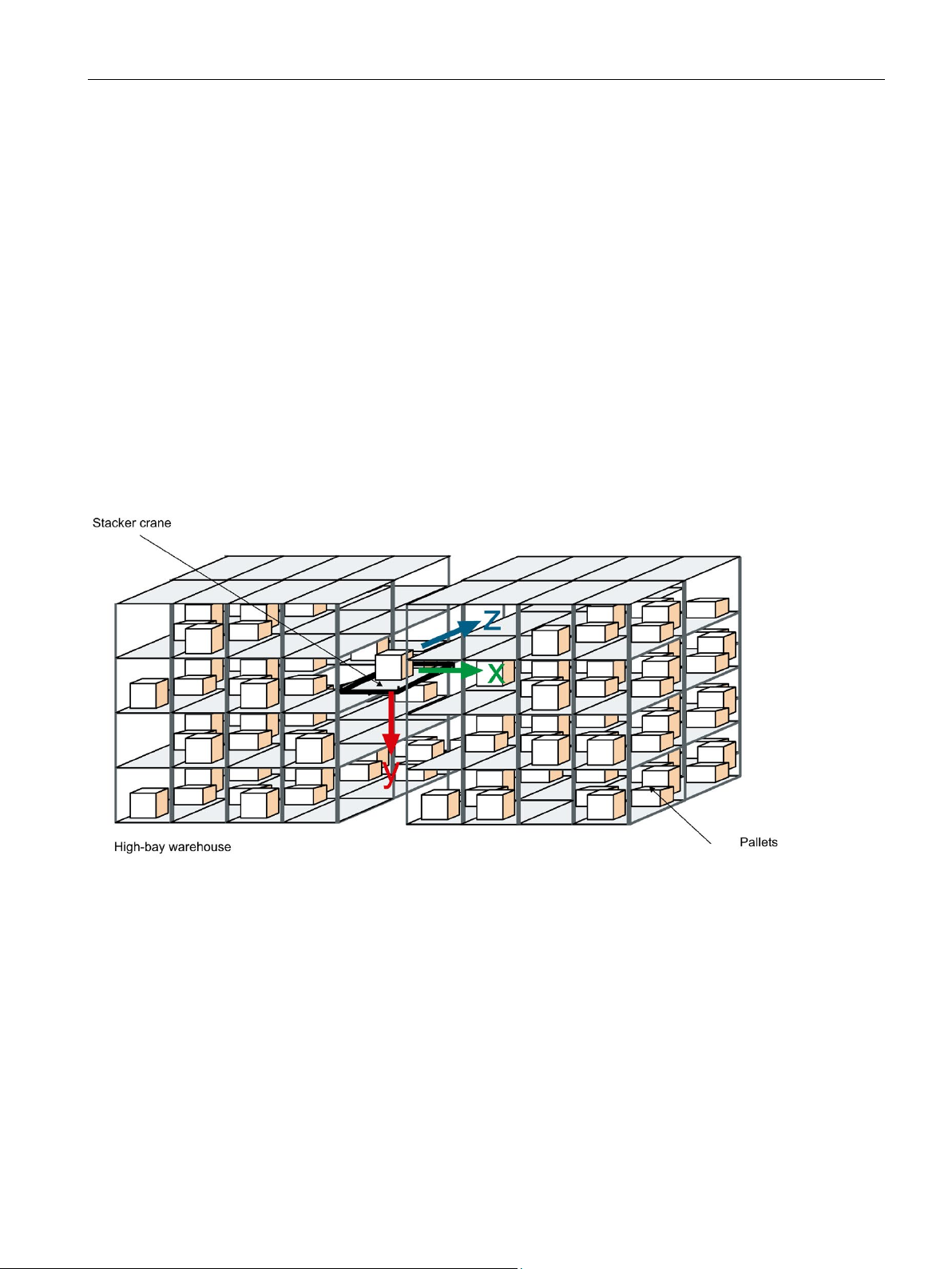
A logistics company needs a matching automation solution for controlling the storage and
retrieval unit in a high-bay warehouse.
The failure of a controller would have serious consequences. After the system restart, you
would have to reposition the storage and retrieval units and record the content of the
containers again. The automation solution must ensure that no data is lost if a CPU fails and
that the warehouse can continue to operate.
To store goods in and retrieve them from the bays, the storage and retrieval unit moves
along an X, Y and Z axis. If the process is interrupted, data can be lost and the location of
the goods is not known. To guard against the loss of data, the storage and retrieval unit is
controlled by the S7-1500R redundant system.
Figure 2-2 Example: High-bay warehouse
If one CPU fails, the second CPU maintains control of the process. The project data and the
user program are saved redundantly and are not lost if a CPU fails. Once you have replaced
the defective CPU and switched it to RUN, the redundant system automatically synchronizes
the project data with the user program in the new CPU. The solution saves you service time
and downtime costs for the warehouse.
S7-1500R/H redundant system
System Manual, 10/2018, A5E41814787-AA
17
Page 19
System overview
Example 3: Avoiding equipment and material damage
Automation task
Feature
Solution
Benefits
2.1 What is the S7-1500R/H redundant system?
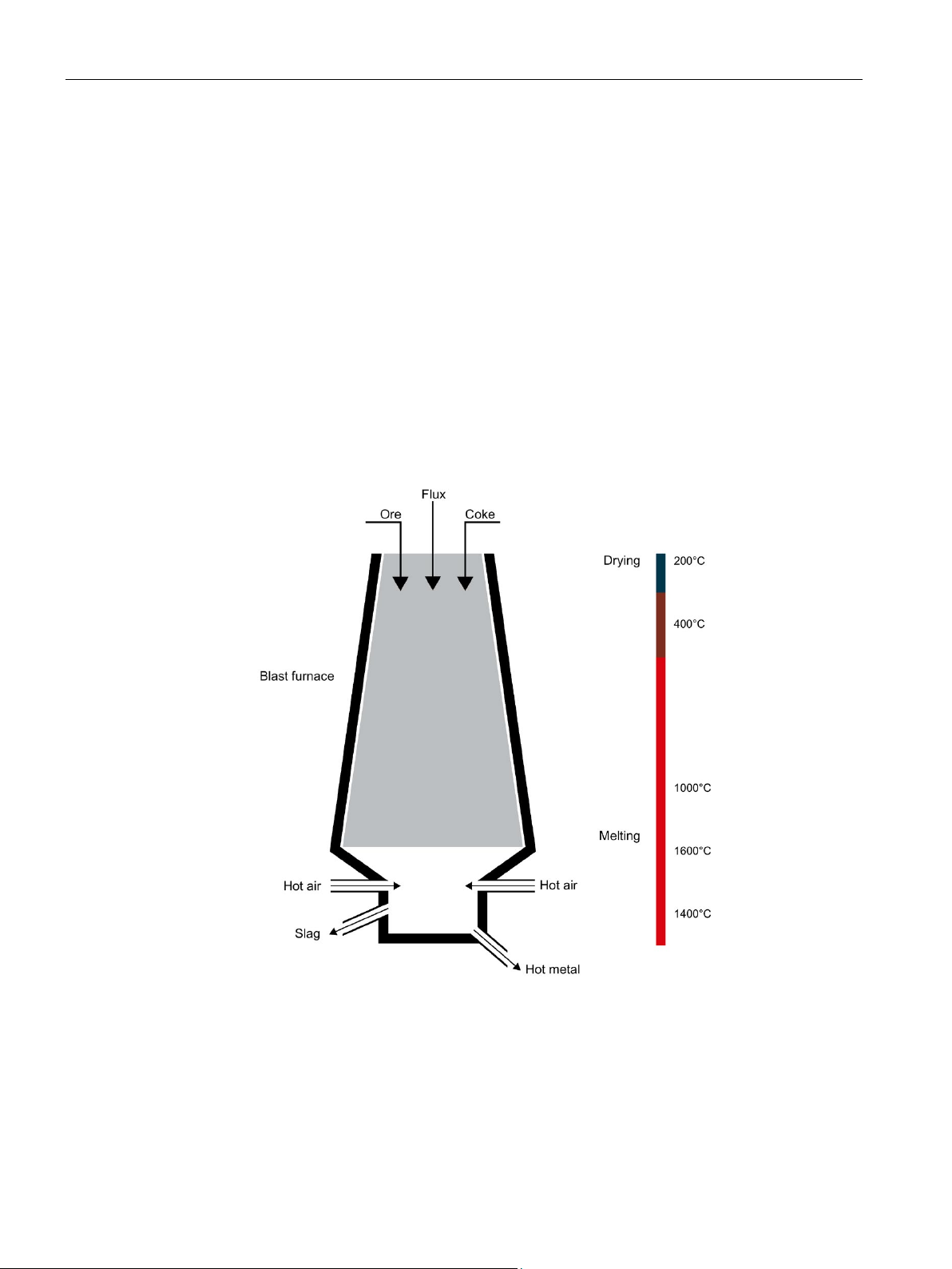
A steel works needs a matching automation solution to control a blast furnace for the steel
production.
Failures, especially in the process industry, can result in damages to the system, workpieces
or material. In a steelworks, there is a danger of the pig iron cooling if the process is
interrupted. The pig iron then cannot be used for the production of steel. The automation
solution must ensure that the plant continues to run if a CPU fails and that the material is not
damaged.
The S7-1500R redundant system controls the blast furnace. The distributed automation
components of the redundant system control the temperature, volume and pressure
parameters.
Figure 2-3 Example: Blast furnace
The S7-1500R redundant system compensates for the possible failure of a CPU or
redundant connection. You do not have to interrupt the smelting process when replacing a
CPU while the plant is running. Uninterrupted plant operation avoids high restart and
material costs.
S7-1500R/H redundant system
18 System Manual, 10/2018, A5E41814787-AA
Page 20
System overview
2.1.2
Operating principle of the S7-1500R/H redundant system
Introduction
S7-1500 design and operating principle
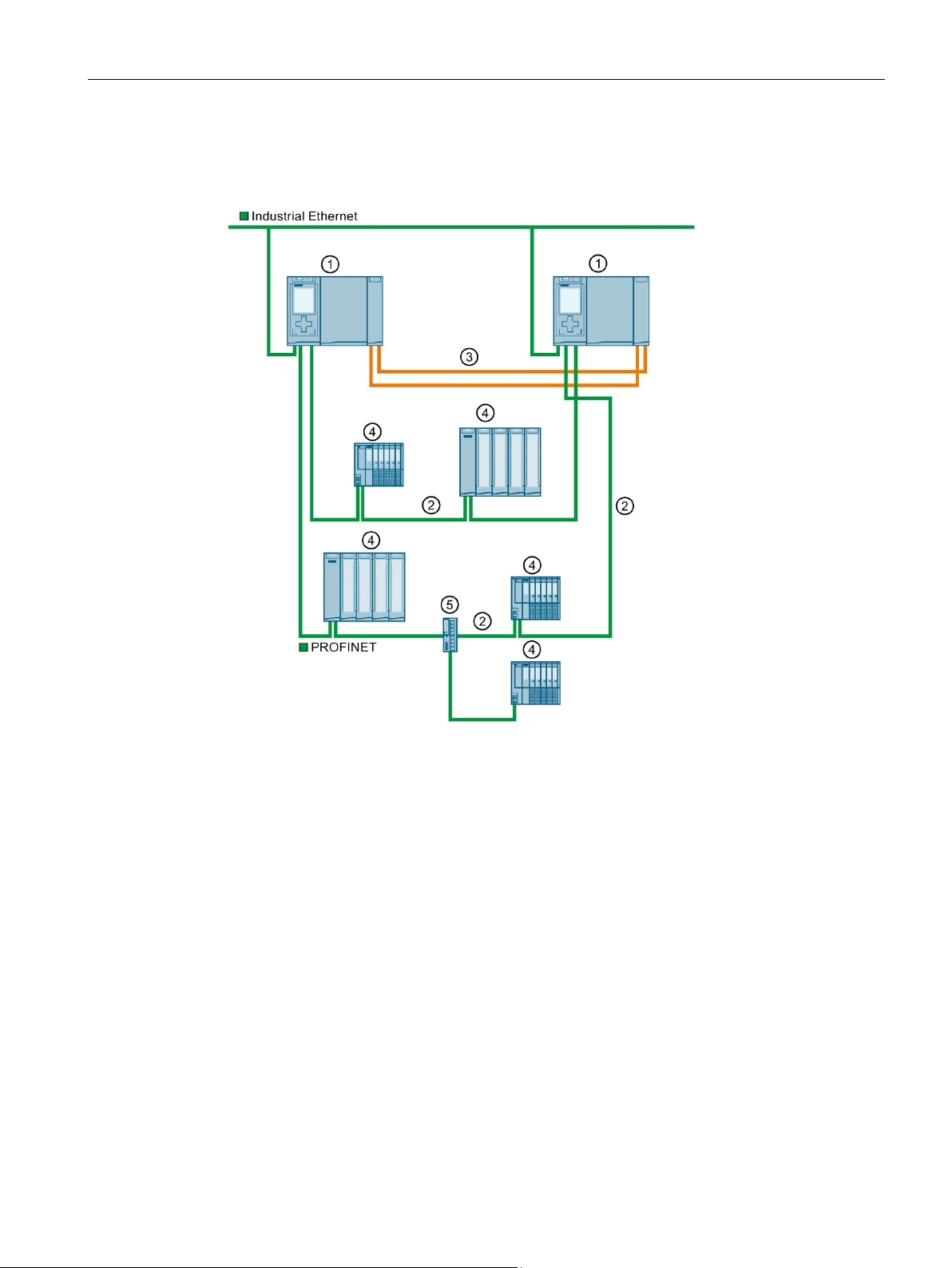
①
S7-1500R CPU
②
PROFINET cable (redundancy connections, PROFINET ring)
③
IO device
④
Switch
2.1 What is the S7-1500R/H redundant system?
S7-1500R/H redundant systems tolerate the failure of one of the two CPUs or an interruption
in the PROFINET ring. The S7-1500R and S7-1500H systems differ in structure,
configuration limits and performance.
The figure below shows the typical structure of the S7-1500R redundant system.
Figure 2-4 Structure of an S7-1500R redundant system
S7-1500R/H redundant system
System Manual, 10/2018, A5E41814787-AA
19
Page 21

System overview
2.1 What is the S7-1500R/H redundant system?
The S7-1500R redundant system consists of:
● Two S7-1500R CPUs
● A PROFINET ring with the Media Redundancy Protocol
● IO devices
● if needed, Switches
All PROFINET IO devices assigned to the S7-1500R system must support system
redundancy S2. These PROFINET IO devices can be located in the PROFINET ring or they
can be separated with a switch.
All PROFINET devices in the PROFINET ring must support media redundancy (MRP). The
H-Sync forwarding function is also recommended. System redundancy S2 is not a
prerequisite. For example, you can use switches and HMI devices without system
redundancy S2.
The redundancy connections in an S7-1500R system are the PROFINET ring with MRP
The two CPUs must be directly connected to each other with a PROFINET cable. All nodes
can still communicate with each other in the event of an interruption in the ring. PROFINET
devices that do not support MRP must be separated from the ring with a switch
One of the two CPUs in the redundant system takes on the role of primary CPU. The other
CPU takes on the role of the following CPU (backup CPU). The role of the CPUs can change
during operation. Synchronization of primary and backup CPU ensures rapid switchover
between CPUs in the event of a failure of the primary CPU. If the primary CPU fails, the
backup CPU takes over control of the process as the new primary CPU.
The redundancy connections use part of the bandwidth on the PROFINET cable for the
synchronization of the R-CPUs. This bandwidth is therefore not available for PROFINET IO
communication.
③
①
②
④
②.
④.
S7-1500R/H redundant system
20 System Manual, 10/2018, A5E41814787-AA
Page 22
System overview
S7-1500H structure and operating principle
①
S7-1500H CPU
②
PROFINET cable (PROFINET ring)
③
Redundancy connections (fiber-optic cables)
④
IO device
⑤
Switch
2.1 What is the S7-1500R/H redundant system?
The figure below shows the typical structure of the S7-1500H redundant system.
Figure 2-5 Structure of an S7-1500H redundant system
S7-1500R/H redundant system
System Manual, 10/2018, A5E41814787-AA
21
Page 23

System overview
2.1 What is the S7-1500R/H redundant system?
The S7-1500H redundant system consists of:
● Two S7-1500H CPUs
● A PROFINET ring with the Media Redundancy Protocol
● Two redundancy connections
● IO devices
● if needed, Switches
All nodes in the redundant system must support system redundancy S2 and media
redundancy (MRP).
All PROFINET IO devices assigned to the S7-1500H system must support system
redundancy S2. These PROFINET IO devices can be located in the PROFINET ring or they
can be separated with a switch.
All PROFINET devices in the PROFINET ring must support media redundancy (MRP).
System redundancy S2 is not a prerequisite. For example, you can use switches and HMI
devices without system redundancy S2.
As with S7-1500R, the S7-1500H redundant system requires a PROFINET ring
the CPUs. All nodes can still communicate with each other in the event of an interruption in
the ring. Devices that do not support MRP must be separated from the ring with a switch
Unlike in S7-1500R, the PROFINET ring and redundancy connections in S7-1500H are
separate. The two redundancy connections are fiber-optic cables that connect the CPUs
directly over synchronization modules
One of the two CPUs in the redundant system takes on the role of primary CPU. The other
CPU takes on the role of the following CPU (backup CPU). The role of the CPUs can change
during operation.
④
①
②
③
⑤
② closed by
⑤.
③.
Synchronization of primary and backup CPU ensures rapid switchover between CPUs in the
event of a failure of the primary CPU. If the primary CPU fails, the backup CPU takes over
control of the process as the new primary CPU.
The synchronization of the H-CPUs does not affect the bandwidth on the PROFINET.
S7-1500R/H redundant system
22 System Manual, 10/2018, A5E41814787-AA
Page 24

System overview
Differences between S7-1500R and S7-1500H
S7-1500R
S7-1500H
CPU 1513R-1 PN
CPU 1515R-2 PN
CPU 1517H-3 PN
Performance
Hardware
Range
Configuration limits
2.1 What is the S7-1500R/H redundant system?
Table 2- 1 S7-1500R and S7-1500H system differences
• Transfer rate of 100 Mbps (for synchronization
and communication)
• Data work-memory:
– CPU 1513R-1 PN: max. 1.5 MB
– CPU 1515R-2 PN: max. 3 MB
• Code work-memory:
– CPU 1513R-1 PN: max. 300 KB
– CPU 1515R-2 PN: max. 500 KB
• The CPUs are identical in design with the
respective S7-1500 standard versions.
• Synchronization of the CPUs takes place over
the PROFINET ring.
• The H-Sync forwarding function is recom-
mended for all nodes in the PROFINET ring.
• Part of the bandwidth on the PROFINET cable
is required for synchronization of the CPUs.
Less bandwidth is therefore available for
PROFINET IO communication.
• Distance between the two R-CPUs:
– Max. 100 m without media converter
– Several kilometers with media converter
(depends on the media converter used)
• In the PROFINET ring: Max. 50 PROFINET
devices, including R-CPUs (max. 16
PROFINET devices recommended)
• In the PROFINET ring and separated with
switches (line): Max. 66 PROFINET devices
(including R-CPUs)
• Significantly greater performance than
S7-1500R due to
– separate redundancy connections over fi-
ber-optic cable
– high computing power
• transfer rate of 1 Gbps (for synchronization)
• Data work-memory: max. 8 MB
• Code work-memory: max. 2 MB
• Each CPU has two optical interfaces.
• Synchronization of the CPUs runs separately
from the PROFINET ring over fiber-optic cables.
• The full bandwidth of the PROFINET cable is
available for PROFINET IO communication.
• Distance between the two H CPUs:
– Maximum of 10 km (depends on the syn-
chronization modules used)
• In the PROFINET ring: Max. 50 PROFINET
devices (including H-CPUs)
• In the PROFINET ring and separated with
switches (line): Max. 258 PROFINET devices
(including H-CPUs)
S7-1500R/H redundant system
System Manual, 10/2018, A5E41814787-AA
23
Page 25

System overview
Comparison of S7-1500 standard system and S7-1500R/H
S7-1500
S7-1500R/H
CPU 1513-1 PN
CPU 1515-2 PN
CPU 1517-3 PN/DP
CPU 1513F-1 PN
CPU 1515F-1 PN
CPU 1517F-3 PN/DP
CPU 1513R-1 PN
CPU 1515R-2 PN
CPU 1517H-3 PN
Support for distributed I/O
✓ ✓ ---
Configuration control
✓ ✓ ---
✓ ✓
CPU redundancy
---
---
✓
System redundancy S2
---
---
✓
Isochronous mode
✓ ✓ ---
Shared Device ✓ ✓
---
IRT
✓ ✓ ---
MRP
✓ ✓ ✓
MRPD ✓ ✓
---
OPC UA ✓ ✓
---
Motion Control ✓ ✓
---
PID control ✓ ✓
✓1)
Security Integrated
✓ ✓ ✓
Protection function: Copy protection
✓ ✓ ---
Safety mode 2)
--- ✓ ---
Integrated system diagnostics
✓ ✓ ✓
1)
2)
For personal, environmental or investment protection, you will need fail-safe automation systems (F-systems).
2.1 What is the S7-1500R/H redundant system?
The table below sets out the key features of comparable CPUs of the S7-1500 automation
system and of the S7-1500R/H redundant system.
Table 2- 2 S7-1500 and S7-1500R/H comparison
Web server
Only support the PID basic functions (do not support PID_Compact, PID _3Step or PID_Temp).
---
S7-1500R/H redundant system
24 System Manual, 10/2018, A5E41814787-AA
Page 26
System overview
2.1.3
Plant components and automation levels
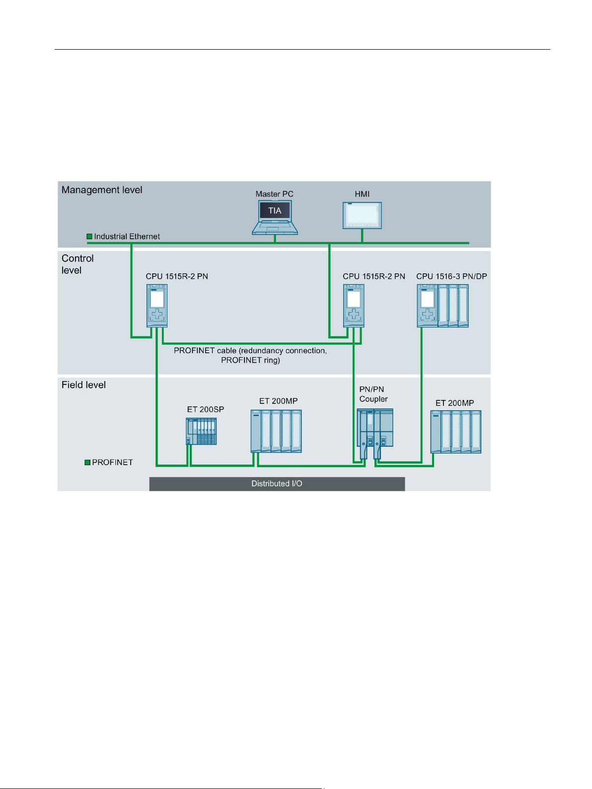
Plant components and automation levels
2.1 What is the S7-1500R/H redundant system?
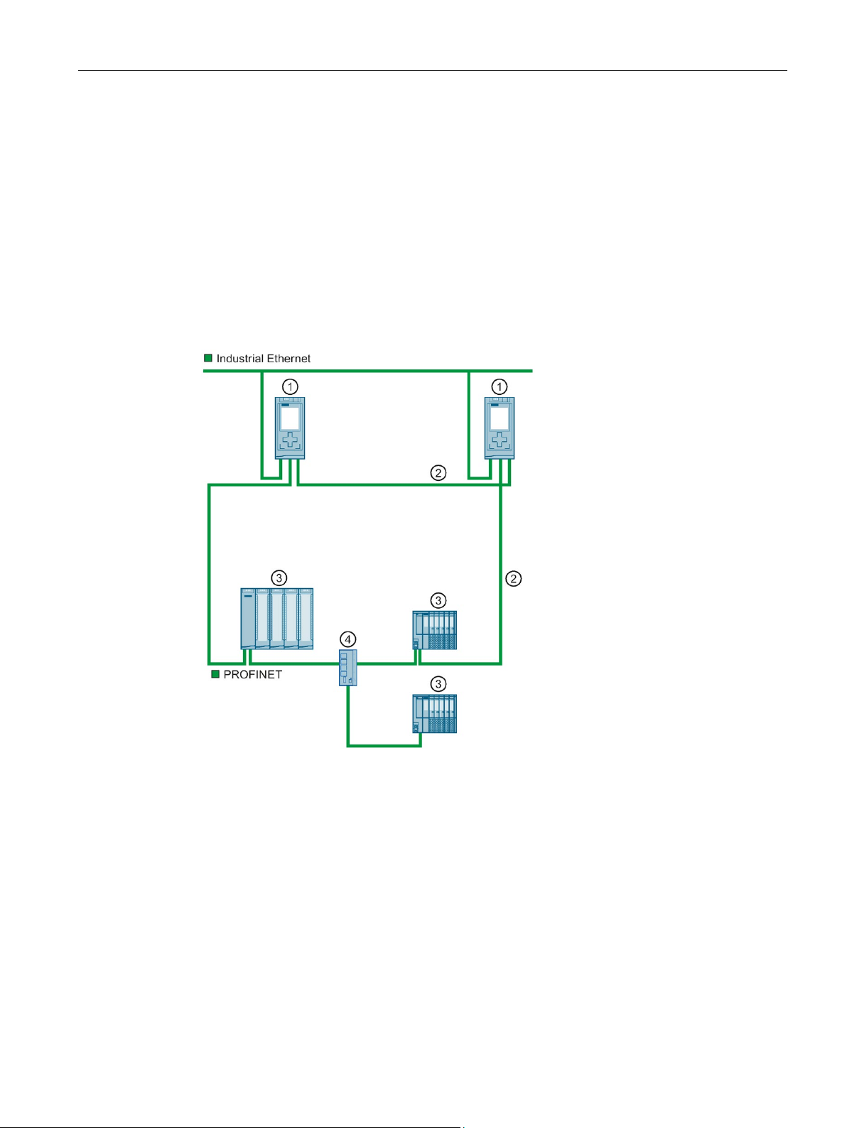
The schematic diagram below shows the key components of the redundant system from the
management level to the control level and the field level.
Figure 2-6 Possible configuration at the management, control and field level using the example of S7-1500R
From the management level, the master PC accesses the various devices at the control and
field level. The master PC is connected to the CPUs over Industrial Ethernet.
The R-CPUs at the control level are redundant in design. The IO devices at the field level are
connected to the R-CPUs within a PROFINET ring.
The redundant S7-1500R system cyclically exchanges IO data with another PROFINET IO
system via a PN/PN coupler. The left-hand side of the PN/PN coupler is assigned to the
S7-1500R redundant system. The right-hand side of the PN/PN coupler is assigned to the
CPU 1516-3 PN/DP (IO controller).
The configuration tolerates the failure of one CPU or an interruption in the PROFINET ring.
The primary CPU and the backup CPU execute the user program in parallel. If one CPU
fails, the second CPU maintains control of the process.
If the PROFINET ring is interrupted, for example as a result of a cable break or an IO device
failure, redundancy in the ring is lost. However, the IO devices that have not failed continue
to operate and can be accessed.
S7-1500R/H redundant system
System Manual, 10/2018, A5E41814787-AA
25
Page 27

System overview
2.1.4
Scalability
Introduction
S7-1500R
Note
Recommendation for S7-1500R: Operate a maximum of 16 PROFINET devices (including
R-CPUs) in the PROFINET ring.
The number of devices in the PROFINET ring affects the availability of the S7
system. You should therefore operate no more than 16 PROFINET devices (
CPUs) in the PROFINET ring. Operating significantly more devices in the PROFINET ring
will reduce the availability of the IO devices and the R
The technical specifications in the documentation are based on the recommended maximum
of 16 PR
2.1 What is the S7-1500R/H redundant system?
Redundant systems are more cost-intensive to use than non-redundant systems:
● There are two CPUs.
● The physical connections (PROFINET ring and redundancy connections) can be required
over large distances.
The S7-1500R/H redundant system is scalable. In other words, the S7-1500R and S7-1500H
systems have the same functional scope, but differ in terms of:
● Performance
● Hardware
● Range
● Configuration limits
● Costs
You connect the CPUs to the Industrial Ethernet over X2 PROFINET interfaces of CPUs S71515R-2 PN or using an additional switch.
S7-1500R supports the following number of PROFINET devices (switches, S7-1500R/H
CPUs, S7-1500 CPUs (V2.5 or later), HMI devices, and IO devices such as ET 200MP and
ET 200SP):
● In the PROFINET ring: max. 50 (recommended: max. 16)
● In the PROFINET ring and separated with switches (line): max. 66
-1500R
including R-
-CPUs.
OFINET devices in the ring in S7-1500R.
S7-1500R/H redundant system
26 System Manual, 10/2018, A5E41814787-AA
Page 28
System overview
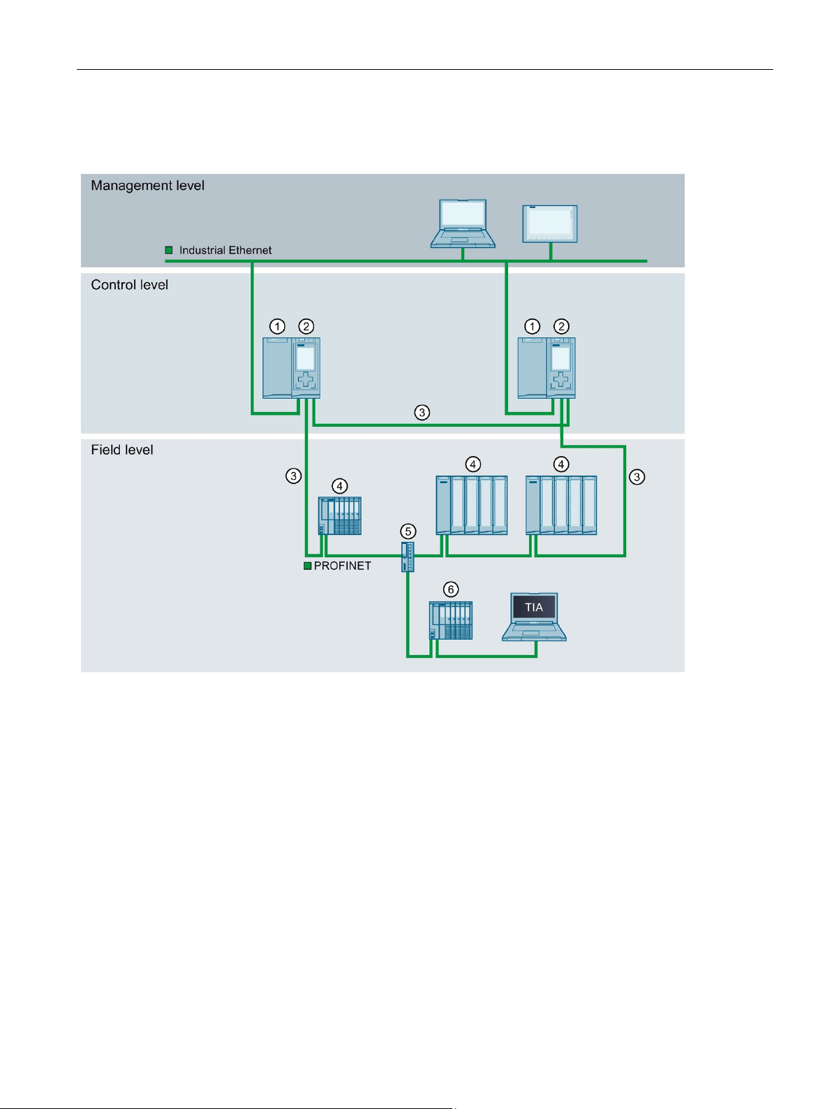
①
Load power supply (optional)
②
CPU S7-1515R-2 PN
③
PROFINET cable (redundancy connections, PROFINET ring)
④
IO device in the PROFINET ring
⑤
Switch
⑥
IO device outside the PROFINET ring (separated with a switch)
2.1 What is the S7-1500R/H redundant system?
The redundancy connections in S7-1500R are the PROFINET ring with MRP. The CPUs are
synchronized over the PROFINET ring.
Figure 2-7 S7-1500R configuration version
S7-1500R/H redundant system
System Manual, 10/2018, A5E41814787-AA
27
Page 29
System overview
S7-1500H
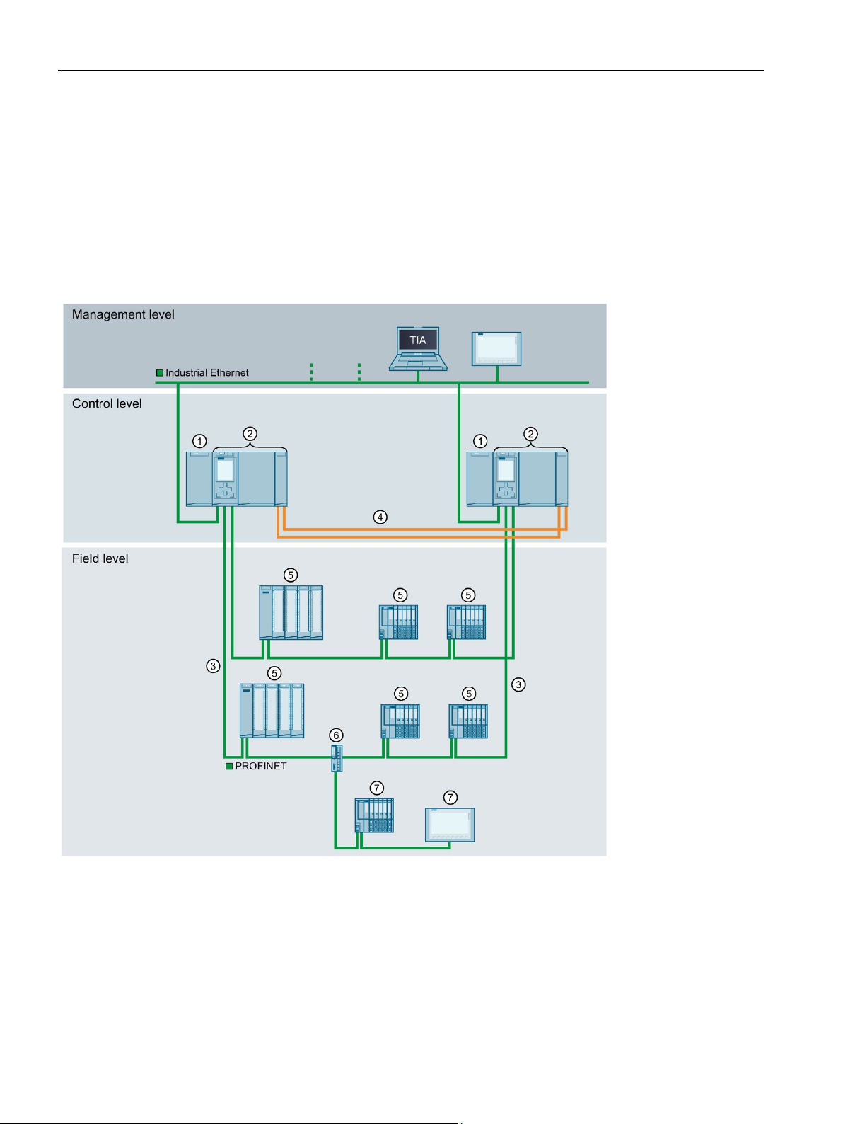
①
Load power supply (optional)
②
CPU 1517H-3 PN
③
PROFINET cable (redundancy connections, PROFINET ring)
④
Redundancy connections (two duplex fiber-optic cables)
⑤
IO device in the PROFINET ring
⑥
Switch
⑦
IO device outside the PROFINET ring (separated with switch)
2.1 What is the S7-1500R/H redundant system?
You connect the CPUs to the Industrial Ethernet over a PROFINET interface or using an
additional switch.
S7-1500H supports the following number of PROFINET devices (switches, S7-1500R/H
CPUs, S7-1500 CPUs (V2.5 or later) and HMI devices):
● In the PROFINET ring: max. 50
● In the PROFINET ring and separated with switches (line): max. 258
The redundancy connections in S7-1500H are two duplex fiber-optic cables that connect the
CPUs directly with plug-in synchronization modules.
Figure 2-8 S7-1500H configuration version
S7-1500R/H redundant system
28 System Manual, 10/2018, A5E41814787-AA
Page 30
System overview
2.1.5
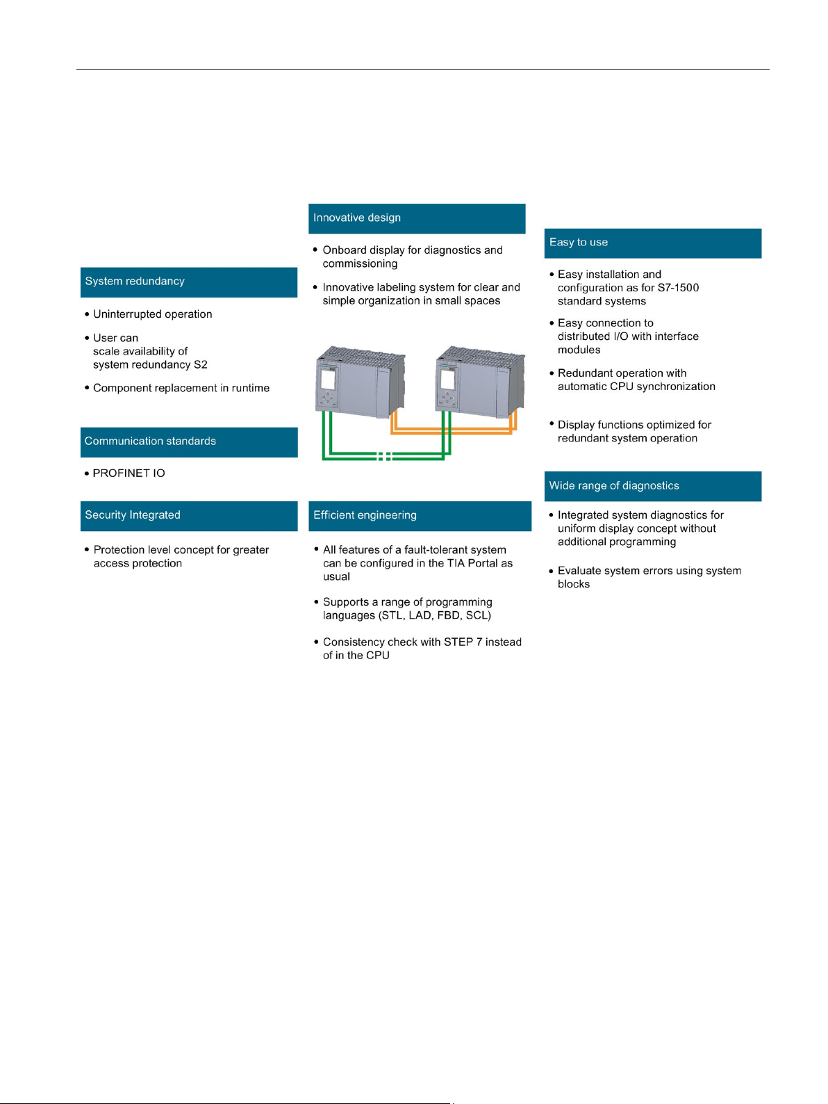
Overview of features
2.1 What is the S7-1500R/H redundant system?
The S7-1500R/H redundant system meets all the requirements for a fault-tolerant system.
The figure below sets out the main features.
Figure 2-9 S7-1500R/H features
S7-1500R/H redundant system
System Manual, 10/2018, A5E41814787-AA
29
Page 31

System overview
2.2
Configuration
2.2.1
Structure of the S7-1500R redundant system
Configuration
2.2 Configuration
The S7-1500R redundant system comprises the following components:
● Two R-CPUs
● Two SIMATIC memory cards
● PROFINET cable (redundancy connections, PROFINET ring)
● IO devices
● Load power supply (optional)
● System power supply (optional)
The S7-1500R redundant system should be installed either on one shared mounting rail or
on two separate mounting rails. Connecting the PROFINET cable to the PROFINET
interfaces X1 P2 R of the CPUs directly connects the two CPUs. You set up the PROFINET
ring from the first CPU to the IO devices and the second CPU with the PROFINET interfaces
X1 P1 R of the CPUs.
S7-1500R/H redundant system
30 System Manual, 10/2018, A5E41814787-AA
Page 32

System overview
Configuration example
①
Optional load or system power supply
②
CPU
③
Mounting rail with integrated DIN rail profile
④
PROFINET cable (redundancy connections, PROFINET ring)
2.2.2
Structure of the S7-1500H redundant system
Configuration
2.2 Configuration
Figure 2-10 S7-1500R configuration example
The S7-1500H redundant system comprises the following components:
● Two H-CPUs
● Two SIMATIC memory cards
● Four synchronization modules (two synchronization modules in each H-CPU)
● Two redundancy connections (two duplex fiber-optic cables)
● IO devices
● Load power supply (optional)
● System power supply (optional)
The S7-1500H redundant system should be installed either on one shared mounting rail or
on two separate mounting rails. You connect the two CPUs with fiber-optic cables to two
synchronization modules in each CPU. You set up the PROFINET ring with the PROFINET
interfaces X1 P1 R and X1 P2 R of the CPUs.
S7-1500R/H redundant system
System Manual, 10/2018, A5E41814787-AA
31
Page 33

System overview
Configuration example
①
Optional load or system power supply
②
CPU (with two synchronization modules, connected underneath, not visible in the diagram)
③
Mounting rail with integrated DIN rail profile
④
Redundancy connections (fiber-optic cables)
⑤
PROFINET cable (PROFINET ring)
2.2 Configuration
Figure 2-11 S7-1500H configuration example
S7-1500R/H redundant system
32 System Manual, 10/2018, A5E41814787-AA
Page 34

System overview
2.2.3
Components
Components of the S7-1500R/H redundant system
Component
Function
Diagram
2.2 Configuration
Table 2- 3 S7-1500R/H components
Mounting rail The mounting rail is the rack of the S7-1500R/H automation
system. You can use the entire length of the mounting rail.
You can order the mounting rail as Accessories/spare parts
(Page 305).
PE connection element for mounting rail
R/H-CPUs The CPU runs the user program.
The screw set is inserted in the mounting rail's T-profile
groove, and is required for grounding the mounting rail.
The set of screws is included in the scope of delivery of the
mounting rails in the standard lengths (160 mm to 830 mm)
and can be ordered as Accessories/spare parts (Page 305).
Additional features and functions of the CPU:
• Communication via Industrial Ethernet
• Communication via PROFINET IO
• Redundant mode
• HMI communication
• Integrated system diagnostics
• Integrated protection functions (access and know-how
protection)
PROFINET cable You connect the CPUs and the IO devices in a PROFINET
S7-1500R/H redundant system
System Manual, 10/2018, A5E41814787-AA
ring using PROFINET cables.
33
Page 35

System overview
Component
Function
Diagram
ply and can be ordered as spare part.
2.2 Configuration
Synchronization modules (for S7-1500H)
Fiber-optic cable (for
S7-1500H)
4-pin connection plug
for CPU supply voltage
System power supply
(PS)
You create two redundancy connections between the H-CPUs
with fiber-optic cables using a total of four synchronization
modules (two in each H-CPU).
The following synchronization module versions can be ordered:
• Sync module 1 GB FO 10 m: for fiber-optic cables up to
10 m in length
• Sync module 1 GB FO 10 km: for fiber-optic cables up to
10 km in length
You connect the two synchronization modules for each CPU in
a pair with a fiber-optic cable. The following lengths of fiberoptic cables can be ordered:
• 1 m
• 2 m
• 10 m
• Up to 10 km (on request)
The 4-pin connection plug provides the supply voltage.
The system power supply can be connected to the backplane
bus using a U connector. In the S7-1500R/H redundant system, the system power supply does not support diagnostics.
Various models of system power supplies are available:
• PS 25 W 24 V DC
• PS 60 W 24/48/60 V DC
• PS 60 W 24/48/60 V DC HF
Extended retentivity of the PS is not supported in S71500R/H.
• PS 60 W 120/230 V AC/DC
A power cable connector with coding element and U connector
is included in the scope of delivery for the system power sup-
Load power supply
(PM)
The load power supply (PM) supplies the system power supply
(PS) and central modules (CPU) with 24 V DC.
If you are using load power supplies, we recommend the devices from our SIMATIC series. These devices can be mounted on the mounting rail.
Various models of load power supply are available:
• PM 70 W 120/230 V AC
• PM 190 W 120/230 V AC
S7-1500R/H redundant system
34 System Manual, 10/2018, A5E41814787-AA
Page 36

System overview
2.3
S7-1500 R/H-CPUs
2.3.1
Overview of the CPU technical specifications
CPU 1513R-1 PN
CPU 1515R-2 PN
CPU 1517H-3 PN
Data work-memory, max.
1.5 MB
3 MB
8 MB
Code work-memory, max.
300 KB
500 KB
2 MB
Plug-in load memory (SIMATIC memory
card), max.
32 GB
32 GB
32 GB
I/O address area, max.
32 KB/32 KB
32 KB/32 KB
32 KB/32 KB
PROFINET IO interfaces
1 1 1
PROFINET interfaces
- 1 1
Processing time for bit operations
0.04 μs
0.03 μs
0.002 μs
Display screen size
3.45 cm
6.1 cm
6.1 cm
Suitable PROFINET devices (switches,
PROFINET ring, max.
50 (recommended: max.
50 (recommended: max.
50
Suitable PROFINET devices (see
rated with switches (line), max.
66
66
258
Modules per rack, max.
2 (PM/PS and CPU)
2 (PM/PS and CPU)
2 (PM/PS and CPU)
Distance between CPUs, max.
Depends on media con-
100 m)
Depends on media con-
100 m)
Depends on the synchro-
Redundancy connections (synchronization link)
PROFINET ring
PROFINET ring
Fiber-optic cable
System redundancy
Yes
Yes
Yes
Switchover time 1)
300 ms
300 ms
50 ms
1)
The switchover time is the time between failure of the primary CPU until the backup CPU takes over control of the
process as the primary CPU at the point of interruption. The switchover time can lengthen the cycle time.
2.3 S7-1500 R/H-CPUs
The S7-1500R/H redundant system tolerates the failure of one of the two R- or H-CPUs in
the PROFINET ring. If the primary CPU fails, the backup CPU takes over control of the
process as the new primary CPU at the point of the interruption.
All relevant data is permanently synchronized between the CPUs over the redundancy
connections between primary CPU and backup CPU.
The primary CPU and the backup CPU execute the user program in parallel.
The display of the CPU shows you the control and status information in various menus.
Quick access to diagnostic alarms minimizes plant downtimes in the event of a service call.
For effective commissioning and fast optimization of drives and controls, the CPUs support
trace functions for all CPU tags.
The table below sets out the main technical specifications for the S7-1500 R/H CPUs.
Table 2- 4 Overview of the R/H-CPU technical specifications
S7-1500R/H CPUs, S7-1500 CPUs
(V2.5 or later) and HMI devices) in the
above) in the PROFINET ring and sepa-
16)
verter used (with
PROFINET cable, max.
16)
verter used (with
PROFINET cable, max.
nization module used:
max. 10 km
S7-1500R/H redundant system
System Manual, 10/2018, A5E41814787-AA
35
Page 37

System overview
Reference
2.3.2
Redundancy
Introduction
Media redundancy
2.3 S7-1500 R/H-CPUs
The full technical specifications can be found in the manuals for the CPUs and on the
Internet (https://mall.industry.siemens.com).
The S7-1500R/H redundant system is based on media redundancy (MRP) in the PROFINET
ring.
All PROFINET IO devices assigned to the S7-1500R system must support system
redundancy S2. These PROFINET IO devices can be located in the PROFINET ring or they
can be separated with a switch.
All PROFINET devices in the PROFINET ring must support media redundancy (MRP). The
H-Sync forwarding function is also recommended for S7-1500R. System redundancy S2 is
not a requirement. For example, you can use switches and HMI devices without system
redundancy S2.
Media redundancy is a function for ensuring network and plant availability.
The two CPUs in the redundant system must be located in a PROFINET ring that uses the
MRP media redundancy protocol.
S7-1500R uses the PROFINET ring to synchronize the two CPUs. S7-1500H uses the
redundancy connections over fiber-optic cables to synchronize the two CPUs. The
PROFINET ring (over PROFINET interfaces X1) of the H CPUs is also mandatory for S71500H.
To set up a ring topology with media redundancy, you need to bring together the free ends of
a linear network topology in one device using two ports (ring ports, port label "R"). You
specify the ring ports in the device configuration.
In the S7-1500R/H redundant system, you need to set the media redundancy role for each of
the two CPUs to Manager (Auto). For all other PROFINET devices in the PROFINET ring,
the media redundancy role Client must be configured. There is a communication connection
based on MRP between the redundancy manager and the redundancy clients. The Media
Redundancy Protocol (MRP) automatically reconfigures the data paths between the
individual devices if the ring is interrupted at any point.
You configure the media redundancy role for PROFINET devices with system
redundancy S2 in STEP 7. For switches without system redundancy S2, you set the media
redundancy role to "Client" over the Web interface.
S7-1500R/H redundant system
36 System Manual, 10/2018, A5E41814787-AA
Page 38

System overview
System redundancy S2
Reference
2.3 S7-1500 R/H-CPUs
An IO device with system redundancy S2 supports system redundancy ARs.
In a redundant system, an IO device with system redundancy S2 has a system redundancy
AR with each of the two CPUs (IO controllers). An IO device thus supports ARs of two IO
controllers simultaneously (for the same modules).
A system redundancy AR can be the primary AR or the backup AR. There must only ever be
one primary AR for one IO device at any given time. The other AR, if there is one, must be
the backup AR. An IO device activates the data of the primary AR at the outputs. The data of
the backup AR is merely saved.
● Behavior in the RUN-Redundant system state:
Both CPUs are IO controllers. PROFINET communication runs on both system
redundancy ARs simultaneously, in each case between one of the CPUs (IO controller)
and the IO device. If the primary CPU then fails, the backup CPU becomes the primary
CPU and also switches the backup AR to primary AR. The data of this AR then becomes
active at the outputs.
● Behavior in the RUN-Solo system state:
Only the primary CPU is the IO controller. PROFINET communication runs on the primary
AR between the primary CPU (IO controller) and the IO device. There is no AR between
the backup CPU and the IO device.
In STEP 7, you configure system redundancy S2 for an IO device by assigning the IO device
to both CPUs of the S7-1500R/H redundant system.
Additional information on media redundancy and system redundancy S2 can be found in the
PROFINET function manual
(http://support.automation.siemens.com/WW/view/en/49948856).
S7-1500R/H redundant system
System Manual, 10/2018, A5E41814787-AA
37
Page 39

System overview
2.3.3
Security
Protection functions
Protection function
Description
and an integrated firewall
CPU lock
Protection against unauthorized access by locking the front cover with a seal or a lock
Access protection example
cannot
2.3 S7-1500 R/H-CPUs
Security means the protection of technical systems against sabotage, espionage and human
error.
For the setup of secure networks, the S7-1500R/H redundant system has an integrated
security concept from authorization levels up to block protection:
Table 2- 5 Overview of protection functions
Access protection Protection against unauthorized configuration changes through four authorization levels
Know-how protection Protection against unauthorized access and modifications to algorithms with password
protection
You can choose from four different access levels in the TIA Portal to restrict user access to
functions and memory areas.
Figure 2-12 Access protection
If you only want to allow users access over HMI, for example, select the access level "HMI
access" in the TIA Portal. Only HMI access and access to diagnostics data is then possible
without entering a password.
Users can read and write tags over an HMI device with this access level.
Users
● Download blocks or the hardware configuration to the CPU
● Upload blocks or the hardware configuration from the CPU to the PG/PC
● Run writing test functions
● Change the operating state from the PG/PC
:
● Run firmware updates
S7-1500R/H redundant system
38 System Manual, 10/2018, A5E41814787-AA
Page 40

System overview
Advantages and customer benefits of protection functions
Reference
2.3.4
Diagnostics
2.3 S7-1500 R/H-CPUs
The protection functions listed above protect your investments from unauthorized access
and manipulation, helping to secure plant availability.
You can find additional information on the protection functions described in the section
Protection (Page 168) and in the STEP 7 online help.
Siemens products and solutions are only one element of a comprehensive industrial security
concept. Please note the additional information on Industrial Security
(http://www.siemens.com/industrialsecurity).
All levels of automation in the S7-1500R/H redundant system have integrated diagnostics.
All SIMATIC products have integrated diagnostic functions that you can use to analyze,
localize and log faults and errors efficiently.
System diagnostics is integrated into the firmware of the CPUs and works independently of
the cyclic user program. Faults in the plant are immediately detected and reported on the
display devices.
A uniform display concept visualizes error messages as plain text information over:
● TIA Portal
● HMI devices
● CPU displays
S7-1500R/H redundant system
System Manual, 10/2018, A5E41814787-AA
39
Page 41

System overview
Displaying faults in an IO device
Advantages and customer benefits
2.3 S7-1500 R/H-CPUs
The various components of the S7-1500R/H redundant system are connected over
PROFINET/Industrial Ethernet (IE). The devices detect faults in their modules (for example
IO device ET 200SP) and send diagnostics data to the assigned CPU. The CPU analyzes
this diagnostic information and notifies the connected display media. The information
analyzed is shown in graphic form in the configuration and programming software (TIA
Portal), on the HMI devices and on the CPU displays.
Figure 2-13 Overview of system diagnostics in a plant
Integrated system diagnostics offers the following advantages:
● Diagnostics is always consistent with the actual state of the plant. In S7-1500R/H
redundant mode, the diagnostic information is synchronized between the CPUs.
● The uniform display concept enables efficient error analysis.
● The immediate identification of the error source in the event of an error speeds up
commissioning and minimizes production downtimes.
● By configuring diagnostics events, you tailor the diagnostics to the requirements of your
automation task.
S7-1500R/H redundant system
40 System Manual, 10/2018, A5E41814787-AA
Page 42

System overview
Reference
2.3.5
Trace
Note
Trace restrictions
The S7
SIMATIC memory card.
2.3 S7-1500 R/H-CPUs
You will find more information on diagnostics in the Diagnostics
(https://support.industry.siemens.com/cs/ww/en/view/59192926) function manual.
The trace functionality facilitates troubleshooting and optimization for the user program.
Trace records device tags and evaluates the recordings. This allows you to analyze
defective signal responses. Tags are, for example, drive parameters or the system and user
tags of a CPU. Because the CPU records tags directly, the trace and logic analyzer function
is suitable for monitoring highly dynamic processes.
-1500R/H redundant system does not support the storage of measurements on the
S7-1500R/H redundant system
System Manual, 10/2018, A5E41814787-AA
41
Page 43

System overview
Example of signal response analysis
①
Trace recordings for S7-1500R/H in the project tree
②
Trend diagram
③
Signal table
Advantages and customer benefits
2.3 S7-1500 R/H-CPUs
To analyze a specific signal response, you define the recording and trigger conditions for the
signals to be recorded.
① The trace function can be called in the project tree from the "Traces" folder under the top
CPU of the redundant system.
The trend diagram
lower diagram as a bit track.
The signal table
options for specific properties.
② displays the selected signals of a recording. Bits are shown in the
③ lists the signals of the selected measurement and provides setting
Figure 2-14 Trace measurement for S7-1500R/H
The trace function offers the following advantages:
● Simultaneous recording of up to 16 different signals and up to four separate trace jobs
● A uniform standard for tag analysis that allows even sporadic errors to be located rapidly
S7-1500R/H redundant system
42 System Manual, 10/2018, A5E41814787-AA
Page 44

System overview
Reference
2.4
Communication
2.4.1
System and device IP addresses
Device IP addresses
MAC addresses
System IP addresses
2.4 Communication
You can find additional information on the trace function in the section Test functions
(Page 282) and in the Using the trace and logic analyzer function manual
(http://support.automation.siemens.com/WW/view/en/64897128).
For the interfaces of the CPUs and the IO devices to be accessible, the interfaces require IP
addresses that are unique within the network (device IP addresses).
The CPUs have a unique MAC address for each interface and its ports. The MAC addresses
of the PROFINET ports are needed for the LLDP protocol, for example for the neighborhood
discovery function.
The number range of the MAC addresses is sequential. The first and last MAC addresses
are printed on the rating plate on the right-hand side of each CPU.
In addition to the device IP addresses of the CPUs, the redundant system S7-1500R/H
supports system IP addresses:
● System IP address for the X1 PROFINET interfaces of the two CPUs (system IP address
● System IP address for the X2 PROFINET interfaces of the two CPUs (system IP address
You use the system IP addresses for communication with other devices (for example, HMI
devices, CPUs, PG/PC). The devices always communicate over the system IP address with
the primary CPU of the redundant system. This ensures that the communication partner can
communicate with the new primary CPU (previously backup CPU) in the RUN-Solo system
state after failure of the original primary CPU in redundant operation.
There is a virtual MAC address for each system IP address. The virtual MAC addresses of
the two PROFINET interfaces must be different from each other.
X1)
X2)
You enable the system IP addresses in STEP 7.
You can find information on configuring the system IP addresses and the virtual MAC
addresses in the section Configuration procedure (Page 136).
S7-1500R/H redundant system
System Manual, 10/2018, A5E41814787-AA
43
Page 45

System overview
Advantages of system IP addresses over device IP addresses
Configuration example
Reference
2.4 Communication
● Targeted communication of the communication partner with the primary CPU.
● The S7-1500R/H redundant system can continue to communicate over a system IP
address even if the primary CPU fails.
The figure below shows a configuration in which the S7-1500R/H redundant system
communicates with other devices over the system IP address X2. The other devices are
connected to the S7-1500 redundant system over the X2 PROFINET interfaces.
Figure 2-15 Example: Communication of the S7 1500R/H redundant system over the system IP
address X2
You can find more information on the system IP address in the S7-1500R/H redundant
system in the PROFINET (http://support.automation.siemens.com/WW/view/en/49948856)
function manual.
S7-1500R/H redundant system
44 System Manual, 10/2018, A5E41814787-AA
Page 46

System overview
2.4.2
Integrated interfaces for communication
Communication option
Service available over:
PROFINET inter-
face X1 (device IP
address)
PROFINET inter-
face X2 (device IP
address)1)
System IP ad-
dress (at interfac-
es X1 and X2)
PROFINET IO ✓ ---
---
MRP (Media Redundancy Protocol)
✓
---
---
✓ ✓
diagnostics
✓ ✓
ing
✓
✓
✓
Open User Communication
✓3)
✓3)
✓
tics
Time synchronization
✓ ✓ ---
1)
2)
3)
with S7-1500R/H also fails.
Reference
2.4 Communication
The table below provides an overview of CPU communication options in the S7-1500R/H
redundant system.
Table 2- 6 S7-1500R/H communication options
LLDP (network topology detection)
PG communication for commissioning, testing and
HMI communication for operator control and monitor-
Data exchange via HTTP(S), for example for diagnos-
Not with CPU 1513R-1 PN
Communication mainly over system IP address: If the CPU with the device IP address fails, communication with the HMI
device also fails.
Communication mainly over system IP address: If the CPU with the device IP address fails, Open User Communication
2)
--- --- ---
---
---
2)
For more information on communication options, please refer to the Communication function
manual (https://support.industry.siemens.com/cs/ww/en/view/59192925).
S7-1500R/H redundant system
System Manual, 10/2018, A5E41814787-AA
45
Page 47

System overview
2.4.3
HMI devices
Reference
2.5
Power supply
Power supply
Description
backplane bus via a system power supply.
system power supply (PS) supplies parts of the module electronics and the LEDs.
2.5 Power supply
HMI devices are used for machine-level process visualization and control. You use the same
HMI devices for the S7-1500R/H redundant system as for the standard S7-1500 system.
Using HMI communication, one or more HMI devices exchange data with the CPUs (for
example HMI Basic/Comfort/Mobile Panel).
The connection of the HMI device to the redundant system depends on the specific
application. In STEP 7, you can configure the following communication options:
● The HMI device communicates with the redundant system over the system IP address.
● The HMI device communicates with the R/H-CPUs (for example for diagnostics purposes)
over the device IP addresses.
You can find additional information on using HMI devices in the section Using HMI devices
(Page 92) and in the Communication function manual
(https://support.industry.siemens.com/cs/ww/en/view/59192925).
You can find an overview of all available HMI devices in the Industry Mall
(https://mall.industry.siemens.com/mall/en/WW/Catalog/Products/9109999?tree=CatalogTre
e).
Table 2- 7 Differences between load and system power supplies
Load power supply (PM) The load power supply (PM) supplies the system components, such as the CPU and
System power supply (PS) The system power supply (PS) only supplies system voltage required internally. The
The CPUs of the redundant system have an integrated system power supply. It provides the
necessary power to the backplane bus. You can add one load power supply or one system
power supply each to the integrated system power supply.
The table below sets out the key differences between load power supplies (PM) and system
power supplies (PS).
system power supply (PS). You can install the load power supply directly to the left of
the CPU (without connection to the backplane bus).
Supply of the R/H CPUs with 24 V DC is optional if you supply the voltage for the
S7-1500R/H redundant system
46 System Manual, 10/2018, A5E41814787-AA
Page 48

System overview
2.6
Software
2.6.1
TIA Portal
2.6 Software
The SIMATIC controllers are integrated into the Totally Integrated Automation Portal.
Engineering with TIA Portal offers:
● Configuration and programming
● Shared data management
● A uniform operating concept for control, visualization and drives
The TIA Portal simplifies integrated engineering in all configuration phases of a plant.
Figure 2-16 TIA Portal overview
S7-1500R/H redundant system
System Manual, 10/2018, A5E41814787-AA
47
Page 49

System overview
2.6.2
SINETPLAN
2.6.3
PRONETA
2.6 Software
SINETPLAN (https://www.siemens.com/sinetplan), the Siemens Network Planner, helps you
plan automation systems and networks based on PROFINET. The tool facilitates the
professional and predictive dimensioning of your PROFINET system right from the planning
stage. SINETPLAN also assists with network optimization and helps you to make the best
possible use of network resources and to plan for reserves. This allows you to avoid
problems in commissioning and failures during productive operation even before planned
use. This increases the availability of the production plant and helps improve operational
safety.
The advantages at a glance
● Network optimization thanks to port-specific calculation of the network load
● Increased production availability thanks to online scan and verification of existing systems
● Transparency before commissioning with the import and simulation of existing STEP 7
projects
● Efficiency through securing existing investments in the long term and the optimal use of
resources
SIEMENS PRONETA (PROFINET network analysis) allows you to analyze the plant network
during commissioning. PRONETA features two core functions:
● The topology overview independently scans PROFINET and all connected components.
● The IO check is a rapid test of the wiring and the module configuration of a plant.
SIEMENS PRONETA (https://support.industry.siemens.com/cs/ww/en/view/67460624) is
also available for free on the Internet.
S7-1500R/H redundant system
48 System Manual, 10/2018, A5E41814787-AA
Page 50

3
3.1
Requirements
Introduction
Hardware requirements
Property
Requirement
redundant system.
Table 3- 1 Hardware requirements
Please note the following requirements for use of the S7-1500R/H redundant system.
S7-1500R/H CPUs
PROFINET ring A PROFINET ring is required for all configuration versions (Page 54) of the S7-1500R/H
• Two identical R or H CPUs in the redundant system
• Identical article numbers, function versions and firmware versions for the two CPUs
S7-1500R/H redundant system
System Manual, 10/2018, A5E41814787-AA
49
Page 51

Application planning
Property
Requirement
3.1 Requirements
PROFINET devices
System power supply PS or
load power supply PM
• All PROFINET IO devices assigned to the S7-1500R/H system must support system
redundancy S2. These PROFINET IO devices can be located in the PROFINET ring or
they can be separated with a switch.
• With S7-1500R/H, all PROFINET devices in the PROFINET ring must support the media
redundancy function.
• For S7-1500R, the H-Sync forwarding function1) is also recommended for the PROFINET
devices in the PROFINET ring.
• The following PROFINET IO devices support system redundancy S2, media redundancy
and H-Sync forwarding:
– ET 200SP IM 155-6 PN HF (6ES7155-6AU00-0CN0), FW version V4.2 or later
– ET 200SP IM 155-6 PN/2 HF (6ES7155-6AU01-0CN0), FW version V4.2 or later
– ET 200SP IM 155-6 PN/3 HF (6ES7155-6AU30-0CN0), FW version V4.2 or later
– ET 200MP IM 155-5 PN HF (6ES7155-5AA01-0AB0), FW version V4.2 or later
– PN/PN coupler (6ES7158-3AD10-0XA0), FW version V4.2 or later
• Switches of the product families XC-200, XP-200 and XF-200BA support system redun-
dancy S2, media redundancy and H-Sync-Forwarding, for example SCALANCE XC208
(6GK5208-0BA00-2AC2), FW version V4.0 or later.
• In STEP 7, "Manager (auto)" is set as the media redundancy role for each of the two R/H
CPUs. For all other devices in the PROFINET ring, set "Client" as the media redundancy
role.
• PROFINET devices that do not support system redundancy S2 can be located in the
PROFINET ring or be separated with a switch.
– Switches without system redundancy S2:
Set the media redundancy role to "Client" over the Web interface.
Configure the ring ports in line with the wiring.
– HMI devices without system redundancy S2:
Set the media redundancy role to "Client" in the HMI configuration.
• S7-1500 CPUs: Firmware version V2.5 or later
The redundant system does not recognize the S7-1500 CPUs when calculating the maximum number of IO devices within and outside the PROFINET ring. If you use S7-1500
CPUs, you will have to check the maximum number yourself.
System power supply PS or load power supply PM for the R/H CPUs
The use of the PS or PM is optional.
Suitable system power supplies:
• PS 25 W 24 V DC (not suitable for CPU 1517H-3 PN)
• PS 60 W 24/48/60 V DC
• PS 60 W 24/48/60 V DC HF
• PS 60 W 120/230 V AC/DC
Suitable load power supplies:
• PM 70 W 120/230 V AC
• PM 190 W 120/230 V AC
S7-1500R/H redundant system
50 System Manual, 10/2018, A5E41814787-AA
1)
If you use PROFINET devices that do not support H-Sync Forwarding in S7-1500R,
additional cycle time increases may occur in system state RUN-Redundant. If the cyclic
program exceeds the cycle monitoring time, the timeout OB (OB 80) may be started. You
can find additional information in the section Start events (Page 153).
Page 52

Application planning
Special case: Operating R/H CPU individually
Software requirements
Function
Requirement
STEP 7
SIMATIC STEP 7 Professional, V15.1 or later
3.2
Restrictions compared to the S7-1500 automation system
Introduction
Hardware restrictions
Property
Restriction
power supply
tion control (option handling)
58) function manual.
3.2 Restrictions compared to the S7-1500 automation system
You can operate an R/H CPU as a single CPU. If you do, please note the following:
● You always need to configure two R- or H-CPUs for S7-1500R/H even if you only set up
one.
● The MAINT LED on the CPU is always yellow (maintenance demanded):
– The R/H system is not in redundant mode.
– No partner CPU found.
Table 3- 2 Software requirements
Please note the following restrictions with the S7-1500R/H redundant system compared to
the S7-1500 automation system.
Table 3- 3 Hardware restrictions
Fail-safe modules Fail-safe modules are not supported in the S7-1500R/H re-
Power segment overview with system
Series machine projects, configura-
Central I/O Central I/O is not supported in the hardware configuration of
Cycle and response times Longer cycle and response times: You can find additional
dundant system.
Not supported
Not supported
the S7-1500R/H redundant system.
Exceptions:
• Load power supply (PM)
• System power supply (PS); the PS cannot be configured.
information in the Cycle and response times
(https://support.industry.siemens.com/cs/ww/en/view/591935
S7-1500R/H redundant system
System Manual, 10/2018, A5E41814787-AA
51
Page 53

Application planning
Software restrictions
Function
Restriction
(Page 150).
Firmware update
Firmware update via accessible devices is not supported.
the RUN-Solo system state.
I-device
Cannot be used as I-device1)
IRT
Not supported
Only programmed connections are supported.
Motion Control
Motion Control functions are not supported in the CPUs
MRPD
Not supported
Multiuser Engineering
Not supported
OPC UA
OPC UA (server and client) not supported
system state.
Protection functions
Not supported: Copy protection
CPUs.
Shared Device
Not supported
SIMATIC ProDiag
Not supported
PROFINET interface X2 of the R/H CPUs
3.2 Restrictions compared to the S7-1500 automation system
Table 3- 4 Software restrictions
Instructions Not supported, restrictions for specific instructions: You can
find additional information in the section Restrictions
Display: "Modules" menu command Not supported
Hardware detection in STEP 7 (read
out configuration)
HMI tags The direct entry of tags on the HMI device is only possible in
Configured connections Connection type not support for communication connection.
Online functions
PID controller Compact PID controllers not supported:
Not supported
• Download not possible in the RUN-Redundant system
state
• SIMATIC Automation Tool (SAT tool) not supported
• PID_Compact
• PID_3Step
• PID_Temp
Only the PID basic functions are supported. The PID basic
functions can only be commissioned online in the RUN-Solo
Secure OUC Not supported as certificate management is not possible for
PROFINET send clock 1 ms only
S7 routing No S7 routing between PROFINET interface X1 and
S7-1500R/H redundant system
52 System Manual, 10/2018, A5E41814787-AA
the R/H CPUs:
If you have enabled Secure OUC, you can compile and load
the user program but cannot add certificates to the R/H
Page 54

Application planning
Function
Restriction
points
not support breakpoints" appears.
(measurements in the device) is not supported.
Web server
Not supported
Certificate management
Not supported
1)
Distributed I/O systems can be connected over PN/PN couplers.
3.2 Restrictions compared to the S7-1500 automation system
S7-1500H: Failure of the IO devices
in the PROFINET ring when
PROFINET cables to primary CPU
are disconnected
If you remove both PROFINET cables from the primary CPU
(CPU 1517H-3 PN) in the RUN-Redundant system state,
please note the following:
• The primary CPU can no longer access the IO devices in
the PROFINET ring. The IO devices will return to the substitute values.
• The redundant system will not execute a primary-backup
switchover.
• The redundant system will remain in the RUN-Redundant
system state.
Isochronous mode Isochronous mode is not supported
Test function: Testing with break-
Not supported: In STEP 7, the message "The device does
Trace The storage of measurements on the SIMATIC memory card
S7-1500R/H redundant system
System Manual, 10/2018, A5E41814787-AA
53
Page 55

Application planning
3.3
Configuration versions
Introduction
3.3 Configuration versions
You can configure different versions of the S7-1500R/H redundant system. A PROFINET
ring is essential in all configuration versions.
For the configuration versions of the S7-1500R/H system, there is redundancy for the
following components:
● R/H-CPUs
● Interfaces of synchronization
● Network in the PROFINET ring
This section describes the admissible configuration versions and their advantages/benefits.
The following convention applies:
Figure 3-1 Green traffic light
S7-1500R/H redundant system
54 System Manual, 10/2018, A5E41814787-AA
Page 56

Application planning
3.3.1
S7-1500R/H configuration with IO devices in the PROFINET ring
Introduction
Advantages/benefits
S7-1500R configuration
①
CPU 1
②
CPU 2
③
PROFINET cable (redundancy connections, PROFINET ring)
④
IO device ET 200MP (with system redundancy S2)
⑤
IO device ET 200SP (with system redundancy S2)
3.3 Configuration versions
The following sections set out configurations of the S7-1500R/H redundant system with IO
devices in the PROFINET ring.
● The IO devices are connected in the PROFINET ring with system redundancy.
● The redundant system continues to operate following a cable interruption anywhere in the
PROFINET ring. One of the two communication connections of the IO devices remains. A
SYNCUP is prevented.
Figure 3-2 S7-1500R configuration with IO devices in the PROFINET ring
S7-1500R/H redundant system
System Manual, 10/2018, A5E41814787-AA
55
Page 57

Application planning
S7-1500H configuration
①
CPU 1
②
CPU 2
③
Two fiber-optic cables (redundancy connections)
④
IO device ET 200SP (with system redundancy S2)
⑤
IO device ET 200MP (with system redundancy S2)
⑥
PROFINET cable (PROFINET ring)
3.3 Configuration versions
Figure 3-3 S7-1500H configuration with IO devices in the PROFINET ring
S7-1500R/H redundant system
56 System Manual, 10/2018, A5E41814787-AA
Page 58

Application planning
3.3.2
S7-1500R/H configuration with switches and linear topology
Introduction
Benefits/advantages
S7-1500R configuration
①
CPU 1
②
CPU 2
③
PROFINET cable (redundancy connections, PROFINET ring)
④
IO device ET 200MP (with system redundancy S2)
⑤
IO device ET 200SP (with system redundancy S2)
⑥
Switch
⑦
HMI device
3.3 Configuration versions
The following sections set out configurations of the S7-1500R/H redundant system with
switches and line topology.
● You can use a switch to add an additional line topology to the PROFINET ring. Unlike the
PROFINET ring, the line topology is not redundant.
● PROFINET IO devices assigned to the S7-1500R/H system must always support system
redundancy S2. These PROFINET IO devices can be located in the PROFINET ring or
they can be separated with a switch.
Figure 3-4 S7-1500R configuration with switches and line topology
S7-1500R/H redundant system
System Manual, 10/2018, A5E41814787-AA
57
Page 59

Application planning
S7-1500H configuration
①
CPU 1
②
CPU 2
③
Two fiber-optic cables (redundancy connections)
④
IO device ET 200SP (with system redundancy S2)
⑤
IO device ET 200MP (with system redundancy S2)
⑥
Switch
⑦
PROFINET cable (PROFINET ring)
⑧
HMI device
3.3 Configuration versions
Figure 3-5 S7-1500H configuration with switches and line topology
S7-1500R/H redundant system
58 System Manual, 10/2018, A5E41814787-AA
Page 60

Application planning
3.4
Redundancy scenarios
3.4.1
Introduction
Introduction
3.4 Redundancy scenarios
This section describes possible redundancy scenarios on the basis of various different
configuration versions. The redundancy scenarios do not result in process restrictions. In the
examples shown, the failures are tolerated by the redundant system.
The following convention applies:
Figure 3-6 Yellow traffic light
S7-1500R/H redundant system
System Manual, 10/2018, A5E41814787-AA
59
Page 61

Application planning
3.4.2
Failure of the primary CPU
Introduction
Redundancy scenario
①
Primary CPU → failed
②
Backup CPU → becomes new primary CPU
③
PROFINET cable (redundancy connections, PROFINET ring)
④
IO device ET 200MP
⑤
IO device ET 200SP
Sequence of events
3.4 Redundancy scenarios
The following redundancy scenario describes the effects of a defective primary CPU.
Figure 3-7 Failure of the primary CPU (using S7-1500R as an example)
1. The primary CPU of the redundant system fails in the RUN-Redundant system state.
2. The redundant system switches to the backup CPU. The backup CPU becomes the new
3. The new primary CPU exchanges process data with the IO devices.
4. The redundancy of the system is restricted. The restriction has no impact on the process.
primary CPU. The redundant system switches to the RUN-Solo system state. You can
find additional information on the RUN-Solo system state in the section Operating and
system states (Page 197).
If another system component or another network segment fails, this can result in the
failure of the S7-1500R/H redundant system. You can find additional information in the
section Failure scenarios (Page 72).
S7-1500R/H redundant system
60 System Manual, 10/2018, A5E41814787-AA
Page 62

Application planning
Diagnostics
Note
To get detailed diagnostics information, evaluate the diagnostics buffer.
Solution
3.4 Redundancy scenarios
System state, operating states and error displays after primary-backup switchover:
● Redundant system → RUN-Solo system state
● Primary CPU (previously backup CPU) → RUN operating state
– MAINT LED → yellow light: The R/H system is not in the RUN-Redundant system
state; no partner CPU found in the redundant system.
● Backup CPU (previously primary CPU) → failed
Replace the defective CPU. You can find additional information on the procedure in the
section Replacing defective R/H CPUs (Page 260).
S7-1500R/H redundant system
System Manual, 10/2018, A5E41814787-AA
61
Page 63

Application planning
3.4.3
Failure of the backup CPU
Introduction
Redundancy scenario
①
Primary CPU
②
Backup CPU → failed
③
PROFINET cable (redundancy connections, PROFINET ring)
④
IO device ET 200MP
⑤
IO device ET 200SP
Sequence of events
3.4 Redundancy scenarios
The following redundancy scenario describes the effects of a defective backup CPU.
Figure 3-8 Failure of the backup CPU (using S7-1500R as an example)
1. The backup CPU of the redundant system fails in the RUN-Redundant system state.
2. The redundant system switches to the RUN-Solo system state. You can find additional
3. The primary CPU continues to exchange process data with the IO devices.
4. The redundancy of the system is restricted. The restriction has no impact on the process.
information on the RUN-Solo system state in the section Operating and system states
(Page 197).
If another system component or another network segment fails, this can result in the
failure of the S7-1500R/H redundant system. You can find additional information in the
section Failure scenarios (Page 72).
S7-1500R/H redundant system
62 System Manual, 10/2018, A5E41814787-AA
Page 64

Application planning
Diagnostics
Note
To get detailed diagnostics info
Solution
3.4 Redundancy scenarios
System state, operating states and error displays after primary-backup switchover:
● Redundant system → RUN-Solo system state
● Primary CPU → RUN operating state
– MAINT LED → yellow light: The R/H system is not in the RUN-Redundant system
state. No partner CPU has been found in the redundant system.
● Backup CPU → failed
rmation, evaluate the diagnostics buffer.
Replace the defective CPU. You can find additional information on the procedure in the
section Replacing defective R/H CPUs (Page 260).
S7-1500R/H redundant system
System Manual, 10/2018, A5E41814787-AA
63
Page 65

Application planning
3.4.4
Failure of the PROFINET cable in the PROFINET ring
Introduction
Redundancy scenario
①
Primary CPU
②
Backup CPU
③
PROFINET cable (redundancy connections, PROFINET ring) → interrupted
④
IO device ET 200MP
⑤
IO device ET 200SP
3.4 Redundancy scenarios
The following redundancy scenario describes the effects of a defective PROFINET cable in
the PROFINET ring.
Figure 3-9 Failure of a PROFINET cable in the PROFINET ring (using S7-1500R as an example)
S7-1500R/H redundant system
64 System Manual, 10/2018, A5E41814787-AA
Page 66

Application planning
Sequence of events
Diagnostics
Note
To get detailed diagnostics information, evaluate the diagnostics buffer.
Solution
3.4 Redundancy scenarios
1. A defective or disconnected PROFINET cable interrupts the PROFINET ring of the
redundant system.
2. The redundant system remains in the RUN-Redundant system state: The primary and
backup CPUs remain in the RUN-Redundant operating state.
3. The redundant system selects an alternative connection over the backup CPU. This
allows the redundant system to access all IO devices in the PROFINET ring again.
4. The redundancy of the system is restricted. The restriction has no effect on the process.
In the following examples, other components also fail in the redundancy scenario
described. The result is a failure scenario:
If another system component or another network segment fails, this can result in the
failure of the S7-1500R/H redundant system.
– If the primary CPU fails in addition to a PROFINET cable, the backup CPU switches to
the STOP operating state.
– If the PROFINET cable is also interrupted at another point, IO devices in the
PROFINET ring may fail depending on the location of the interruption.
– You can find additional information in the section Failure scenarios (Page 72).
System state, operating states and error displays after the failure of the PROFINET cable:
● Redundant system → RUN-Redundant system state
● Primary CPU → RUN-Redundant operating state
– MAINT LED → yellow light: The PROFINET ring is open. There is only one redundancy
connection remaining in the redundant system.
● Backup CPU → RUN-Redundant operating state
– MAINT LED → yellow light: The PROFINET ring is open. There is only one redundancy
connection remaining in the redundant system.
Replace the defective PROFINET cable or reconnect the disconnected PROFINET cable.
You can find additional information on the procedure in the section Replacing defective
PROFINET cables.
S7-1500R/H redundant system
System Manual, 10/2018, A5E41814787-AA
65
Page 67

Application planning
3.4.5
Specific redundancy scenarios for S7-1500H
3.4.5.1
Failure of a redundancy connection in S7-1500H
Introduction
Redundancy scenario
①
Primary CPU
②
Backup CPU
③
One fiber-optic cable (redundancy connection) → interrupted
④
IO device ET 200SP
⑤
IO device ET 200MP
⑥
PROFINET cable (PROFINET ring)
3.4 Redundancy scenarios
The following redundancy scenario describes the effects of a defective redundancy
connection in S7-1500H.
Figure 3-10 Failure of a redundancy connection
S7-1500R/H redundant system
66 System Manual, 10/2018, A5E41814787-AA
Page 68

Application planning
Sequence of events
Diagnostics
Note
To get
Solution
3.4 Redundancy scenarios
1. One of the two redundancy connections (fiber-optic cables) is interrupted.
2. The primary CPU continues to exchange process data with the IO devices.
3. The redundancy of the system is restricted. The redundant system will remain in the
RUN-Redundant system state. The restriction has no effect on the process.
If the primary CPU fails as well as the redundancy connection, the backup CPU switches
to the STOP operating state. You can find additional information in the section Failure
scenarios (Page 72).
System state, operating states and error displays after the failure of a redundancy
connection:
● Redundant system → RUN-Redundant system state
● Primary CPU → RUN-Redundant operating state
– MAINT LED → yellow light: There is only one redundancy connection remaining in the
H system.
● Backup CPU → RUN-Redundant operating state
– MAINT LED → yellow light: There is only one redundancy connection remaining in the
H system.
detailed diagnostics information, evaluate the diagnostics buffer.
Replace the defective redundancy connection. You can find additional information on the
procedure in the section Replacing defective redundancy connections (Page 261).
S7-1500R/H redundant system
System Manual, 10/2018, A5E41814787-AA
67
Page 69

Application planning
3.4.5.2
Failure of both redundancy connections in S7-1500H > 1500 ms apart
Introduction
Redundancy scenario
①
Primary CPU (S7-1500H)
②
Backup CPU (S7-1500H)
③
Two fiber-optic cables (redundancy connections) → interrupted
④
IO device ET 200MP
⑤
IO device ET 200SP
⑥
PROFINET cable (PROFINET ring)
3.4 Redundancy scenarios
The following redundancy scenario describes the effects of a defect in each of the two
redundancy connections in S7-1500H. In this redundancy scenario, the time between the
redundancy connection failures is > 1500 ms.
Figure 3-11 Failure of both redundancy connections (> 1500 ms apart)
S7-1500R/H redundant system
68 System Manual, 10/2018, A5E41814787-AA
Page 70

Application planning
Sequence of events
Diagnostics
Note
To get detailed diagnostics information, evaluate the diagnostics buffer.
Solution
3.4 Redundancy scenarios
1. The two redundancy connections (fiber-optic cables) are interrupted, one > 1500 ms after
the other.
2. The redundant system switches to the RUN-Solo system state. The primary CPU remains
in the RUN operating state. The backup CPU switches to the STOP operating state.
3. The primary CPU continues to exchange process data with the IO devices.
4. The redundancy of the system is restricted. The restriction has no impact on the process.
If another system component or another network segment fails, this can result in the
failure of the S7-1500R/H redundant system. You can find additional information in the
section Failure scenarios (Page 72).
System state, operating states and error displays after the failure of both redundancy
connections:
● Redundant system → RUN-Solo system state
● Primary CPU → RUN operating state
– MAINT LED → yellow light: The H-system is not in the RUN-Redundant system state.
No partner CPU has been found in the H-system.
● Backup CPU → STOP operating state
– MAINT LED → yellow light: The H-system is not in the RUN-Redundant system state.
No partner CPU has been found in the H-system.
Replace the defective redundancy connections. You can find additional information on the
procedure in the section Replacing defective redundancy connections (Page 261).
S7-1500R/H redundant system
System Manual, 10/2018, A5E41814787-AA
69
Page 71

Application planning
3.4.5.3
Failure of both redundancy connections and the PROFINET cable in the PROFINET ring
Introduction
Redundancy scenario
①
Primary CPU
②
Backup CPU
③
Two fiber-optic cables (redundancy connections) → interrupted
④
IO device ET 200SP
⑤
IO device ET 200MP
⑥
PROFINET cable (PROFINET ring) → interrupted
3.4 Redundancy scenarios
The following redundancy scenario describes the effects of a defect in each of the two
redundancy connections and in the PROFINET cable in the PROFINET ring.
In this redundancy scenario, the time between the redundancy connection failures is
> 1500 ms.
Figure 3-12 Failure of both redundancy connections and a PROFINET cable in the PROFINET ring
S7-1500R/H redundant system
70 System Manual, 10/2018, A5E41814787-AA
Page 72

Application planning
Sequence of events
Diagnostics
Note
To get detailed diagnostics information, evaluate the diagnostics buffer.
Solution
3.4 Redundancy scenarios
1. Both redundancy connections (fiber-optic cables) fail in the redundant system. The time
between the failures is > 1500 ms.
2. The redundant system switches to the RUN-Solo system state. The primary CPU remains
in the RUN operating state. The backup CPU switches to the STOP operating state.
3. A defective PROFINET cable also interrupts the PROFINET ring.
4. The redundant system accesses all IO devices in the PROFINET ring again over the
remaining PROFINET cables.
5. The redundancy of the system is restricted. The restrictions have no effect on the
process.
System state, operating states and error displays after the failure of the redundancy
connections and PROFINET cable:
● Redundant system → RUN-Solo system state
● Primary CPU → RUN operating state
– MAINT LED → yellow light: The H-system is not in the RUN-Redundant system state.
No partner CPU has been found in the H-system. The PROFINET ring is open.
● Backup CPU → STOP operating state
– MAINT LED → yellow light: The H-system is not in the RUN-Redundant system state.
No partner CPU has been found in the H-system. The PROFINET ring is open.
Replace the defective redundancy connections and the defective PROFINET cable. You can
find more information on the procedure in the following sections:
● Replacing defective redundancy connections (Page 261)
● Replacing defective PROFINET cables
S7-1500R/H redundant system
System Manual, 10/2018, A5E41814787-AA
71
Page 73

Application planning
3.5
Failure scenarios
Introduction
3.5 Failure scenarios
This section describes possible failure scenarios with the various configuration versions. The
failure scenarios lead to process restrictions. In the examples shown, the redundant system
cannot tolerate the failures any longer.
The following convention applies:
Figure 3-13 Red traffic light
S7-1500R/H redundant system
72 System Manual, 10/2018, A5E41814787-AA
Page 74

Application planning
3.5.1
Failure of an IO device in the PROFINET ring
Introduction
Failure scenario
①
Primary CPU
②
Backup CPU
③
PROFINET cable (redundancy connections, PROFINET ring)
④
IO device ET 200MP
⑤
IO device ET 200SP → failed
Sequence of events
3.5 Failure scenarios
The following failure scenario describes the effects of a defective IO device in the
PROFINET ring.
Figure 3-14 Failure of an IO device in the PROFINET ring (using S7-1500R as an example)
1. An IO device in the PROFINET ring fails.
2. The PROFINET ring is interrupted.
3. The redundant system selects an alternative connection over the backup CPU. This
4. The failure of the IO device has an impact on the process. If the failed inputs and outputs
allows the redundant system to access all remaining IO devices in the PROFINET ring
again.
have an important function in the system, their failure can have a critical impact on the
process.
S7-1500R/H redundant system
System Manual, 10/2018, A5E41814787-AA
73
Page 75

Application planning
Diagnostics
Note
To get detailed diagnostics information, evalua
Solution
3.5 Failure scenarios
System state, operating states and error displays after the failure of an IO device:
● Redundant system → RUN-Redundant system state
● Primary CPU → RUN-Redundant operating state
– MAINT LED: → yellow light: The PROFINET ring is open.
– ERROR LED → flashes red: An IO device has failed.
● Backup CPU → RUN-Redundant operating state
– MAINT LED → yellow light: The PROFINET ring is open.
– ERROR LED → flashes red: An IO device has failed.
te the diagnostics buffer.
Replace the defective IO device. You can find additional information on the procedure in the
section Replacing defective I/O devices/switches (Page 268).
S7-1500R/H redundant system
74 System Manual, 10/2018, A5E41814787-AA
Page 76

Application planning
3.5.2
Failure of a switch (with line topology) in the PROFINET ring
Introduction
Failure scenario
①
Primary CPU
②
Backup CPU
③
PROFINET cable (redundancy connections, PROFINET ring)
④
IO device ET 200MP
⑤
IO device ET 200SP
⑥
Switch → failed
⑦
IO device ET 200SP
⑧
HMI device
3.5 Failure scenarios
The following failure scenario describes the effects of a defective switch (with line topology)
in the PROFINET ring.
Figure 3-15 Failure of a switch in the PROFINET ring (using S7-1500R as an example)
S7-1500R/H redundant system
System Manual, 10/2018, A5E41814787-AA
75
Page 77

Application planning
Sequence of events
Diagnostics
Note
To get detailed diagnostics information, evaluate the diagnostics buffer.
Solution
3.5 Failure scenarios
1. A switch (with connected line topology) in the PROFINET ring fails.
2. The PROFINET ring is interrupted.
3. If applicable, the redundant system selects an alternative connection to the IO devices
⑤ over the backup CPU. This allows the redundant system to access all IO devices
and
in the PROFINET ring again.
4. The failure of the switch has an impact on the process as the IO devices in the line
topology can no longer be accessed.
If the failed inputs and outputs have an important function in the system, their failure can
have a critical impact on the process.
System state, operating states and error displays after the failure of a switch:
● Redundant system → RUN-Redundant system state
● Primary CPU → RUN-Redundant operating state
– MAINT LED → yellow light: The PROFINET ring is open.
– ERROR LED → flashes red: One or more IO devices have failed.
● Backup CPU → RUN-Redundant operating state
– MAINT LED → yellow light: The PROFINET ring is open.
– ERROR LED → flashes red: One or more IO devices have failed.
④
Replace the defective switch. You can find additional information on the procedure in the
section Replacing defective I/O devices/switches (Page 268).
S7-1500R/H redundant system
76 System Manual, 10/2018, A5E41814787-AA
Page 78

Application planning
3.5.3
Specific failure scenarios with S7-1500R
3.5.3.1
Two cable interruptions in the PROFINET ring in S7-1500R > 1500 ms apart
Introduction
Failure scenario
①
Primary CPU
②
Backup CPU
③
PROFINET ring → interrupted at two points
④
IO device ET 200MP
⑤
IO device ET 200SP
3.5 Failure scenarios
The following failure scenario describes the effects of two cable interruptions in the
PROFINET ring. In this failure scenario, the time between the two cable interruptions is
> 1500 ms.
Figure 3-16 Two cable interruptions in the PROFINET ring (> 1500 ms apart)
S7-1500R/H redundant system
System Manual, 10/2018, A5E41814787-AA
77
Page 79

Application planning
Sequence of events
Diagnostics
Note
To get detailed diagnostics information, evaluate the diagnostics buffer.
Solution
3.5 Failure scenarios
1. The PROFINET ring is interrupted at one point.
2. The redundant system remains in the RUN-Redundant system state: The primary and
backup CPUs remain in the RUN-Redundant operating state.
3. The PROFINET ring is interrupted at a second point > 1500 ms later.
4. The redundant system switches to the RUN-Solo system state. The primary CPU remains
in the RUN operating state. The backup CPU switches to the STOP operating state.
5. CPU redundancy has failed. The failure has an impact on the process. The RUN-Solo
system state and the cable interruptions mean that not all IO devices in the PROFINET
ring can be accessed.
If the failed inputs and outputs have an important function in the system, their failure can
have a critical impact on the process.
System state, operating states and error displays after the cable interruptions:
● Redundant system → RUN-Solo system state
● Primary CPU → RUN operating state
– MAINT LED → yellow light: The R system is not in the RUN-Redundant system state.
No partner CPU has been found in the R system. The PROFINET ring is open.
– ERROR LED → flashes red: One or more IO devices cannot be accessed.
● Backup CPU → STOP operating state
– MAINT LED → yellow light: The R system is not in the RUN-Redundant system state.
No partner CPU has been found in the R system. The PROFINET ring is open.
– ERROR LED → flashes red: One or more IO devices cannot be accessed.
Replace the defective PROFINET cables. You can find additional information on the
procedure in the section Replacing defective redundancy connections (Page 261).
S7-1500R/H redundant system
78 System Manual, 10/2018, A5E41814787-AA
Page 80

Application planning
3.5.3.2
Two cable interruptions in the PROFINET ring in S7-1500R within ≤ 1500 ms
Introduction
Failure scenario
①
Primary CPU
②
Backup CPU
③
PROFINET ring → interrupted at two points
④
IO device ET 200MP
⑤
IO device ET 200SP
3.5 Failure scenarios
The following failure scenario describes the effects of two cable interruptions in the
PROFINET ring. In this failure scenario, the time between the two cable interruptions is
≤ 1500 ms.
Figure 3-17 Two cable interruptions in the PROFINET ring (within ≤ 1500 ms)
S7-1500R/H redundant system
System Manual, 10/2018, A5E41814787-AA
79
Page 81

Application planning
Sequence of events
WARNING
Undefined system state of the S7-1500R redundant system at the same time as a cable
interruption in the PROFINET ring at two points within ≤ 1500 ms.
Diagnostics
Note
To get detailed diagnostics information, evaluate the diagnostics buffer.
3.5 Failure scenarios
1. The PROFINET ring is interrupted at two points within ≤ 1500 ms.
2. The redundant system switches to an undefined system state: The primary CPU remains
in the RUN operating state. The backup CPU becomes the primary CPU and remains in
RUN operating state.
3. The two primary CPUs continue to exchange process data with the accessible IO
devices.
4. The redundancy of the system is defective. The redundant system is in an undefined
system state. The undefined system state can lead to dangerous states in the process.
Lay the PROFINET cables so that they are securely protected from damage.
PROFINET cables should also always be laid separately from each other. This makes
simultaneous damage to the PROFINET cables (within ≤ 1500 ms) unlikely.
System state and operating states after cable interruptions:
● Redundant system → System state defective (undefined: Each R-CPU is in the RUN-Solo
system state).
● Primary CPU → RUN operating state
– MAINT LED → yellow light: The R system is not in the RUN-Redundant system state.
The PROFINET ring is open.
– ERROR LED → flashes red: An IO device has failed.
● Primary CPU (previously backup CPU) → RUN operating state
– MAINT LED → yellow light: The R system is not in the RUN-Redundant system state.
The PROFINET ring is open.
– ERROR LED → flashes red: An IO device has failed.
S7-1500R/H redundant system
80 System Manual, 10/2018, A5E41814787-AA
Page 82

Application planning
Solution
Note
Before you replace the defective PRO
STOP operating state. Only then repair the PROFINET cables in the PROFINET ring.
Afterwards, switch the R
3.5.3.3
Failure of the primary CPU when IO devices have failed in the PROFINET ring
Introduction
Failure scenario
①
Primary CPU → failed (2nd failure in runtime sequence)
②
Backup CPU → switches to STOP operating state
③
PROFINET cable (redundancy connections, PROFINET ring)
④
IO device ET 200MP
⑤
IO device ET 200SP → failed (1st failure in sequence)
3.5 Failure scenarios
Please note the following solution:
FINET cables, you must switch both R-CPUs to the
-CPUs back to the RUN operating state.
You can find additional information on the procedure in the section Replacing defective
redundancy connections (Page 261).
The following failure scenario describes the effects of a defective IO device in the
PROFINET ring and a defective primary CPU.
Figure 3-18 Failure of an IO device in the PROFINET ring and the primary CPU (using S7-1500R as
an example)
S7-1500R/H redundant system
System Manual, 10/2018, A5E41814787-AA
81
Page 83

Application planning
Sequence of events
Note
The backup CPU does not differentiate between the following scenarios:
•
•
cond point and the primary CPU may
That is why the backup CPU does not become the primary CPU. This prevents an
undefined system state.
Diagnostics
Note
To get detailed diagnostics information, evaluate the d
3.5 Failure scenarios
1. An IO device in the PROFINET ring fails.
2. As a result, the PROFINET ring is interrupted.
3. The redundant system selects an alternative connection over the backup CPU. This
allows the redundant system to access all remaining IO devices in the PROFINET ring
again.
4. The primary CPU also fails.
5. The redundant system does not switch to the backup CPU and switches to the STOP
system state. The role of the backup CPU remains unchanged.
It can no longer access the primary CPU because the latter has failed.
The PROFINET ring has been interrupted at a se
still be running.
6. The redundant system has failed. The process is no longer controlled by the redundant
system.
System state, operating states and error displays after the failure of the IO device in the
PROFINET-Ring and the STOP of Backup CPU:
● Redundant system → STOP system state
● Primary CPU → failed
● Backup CPU → STOP operating state
– MAINT LED → yellow light: The R system is not in the RUN-Redundant system state.
No partner CPU has been found in the R system. The PROFINET ring is open.
– ERROR LED → flashes red: One or more IO devices have failed.
iagnostics buffer.
S7-1500R/H redundant system
82 System Manual, 10/2018, A5E41814787-AA
Page 84

Application planning
Solution
Note
Proceed as follows if yo
state and can access all important IO devices:
1.
2.
3.
3.5 Failure scenarios
Replace the defective IO device and the defective primary CPU. You can find additional
information on the procedure in the sections Replacing defective R/H CPUs (Page 260) and
Replacing defective I/O devices/switches (Page 268).
u have ensured that the CPU is still working in the STOP operating
Replace the defective IO device.
Switch the CPU from STOP operating state to the RUN operating state.
Replace the defective CPU. Switch the new CPU to the RUN operating state.
S7-1500R/H redundant system
System Manual, 10/2018, A5E41814787-AA
83
Page 85

Application planning
3.5.4
Specific failure scenarios with S7-1500H
3.5.4.1
Failure of both redundancy connections in S7-1500H ≤ 1500 ms apart
Introduction
Failure scenario
①
Primary CPU
②
Backup CPU
③
Two fiber-optic cables (redundancy connections) → interrupted
④
IO device ET 200SP
⑤
IO device ET 200MP
⑥
PROFINET cable (PROFINET ring)
3.5 Failure scenarios
The following failure scenario describes the effects of a defect in each of the two redundancy
connections in S7-1500H. In this failure scenario, the time between the redundancy
connection failures is ≤ 1500 ms.
Figure 3-19 Failure of both redundancy connections
S7-1500R/H redundant system
84 System Manual, 10/2018, A5E41814787-AA
Page 86

Application planning
Sequence of events
WARNING
Undefined system state of the S7-1500H redundant system when two redundancy
connections are interrupted ≤ 1500 ms apart.
Diagnostics
Note
To get detailed diagnostics information, evaluate the diagnostics buffer.
Solution
Note
Before you replace the defective redundancy connections, you must switch both H
the STOP operating state. Only then repair the redundancy connections. Switch the H-CPUs
back to the RUN operating state.
3.5 Failure scenarios
1. The two redundancy connections (fiber-optic cables) are interrupted ≤ 1500 ms apart.
2. The redundant system switches to an undefined system state: The primary CPU remains
in the RUN operating state. The backup CPU becomes the primary CPU and remains in
RUN operating state.
3. The two primary CPUs continue to exchange process data with the PROFINET devices.
4. The redundancy of the system is defective. The redundant system is in an undefined
system state. The undefined system state can lead to dangerous states in the process.
Lay the redundancy connections so that the fiber-optic cables are securely protected
from damage. Also make sure when laying the cables that the two redundancy
connections are always separate from each other. This makes simultaneous damage to
the redundancy connections (< 1500 ms apart) unlikely.
System state and operating states after the failure of both redundancy connections:
● Redundant system → System state defective (undefined: Each H-CPU is in the RUN-Solo
system state).
● Primary CPU → RUN operating state
– MAINT LED → yellow light: The H-system is not in the RUN-Redundant system state.
No partner CPU has been found in the H-system.
● Primary CPU (previously backup CPU) → RUN operating state
– MAINT LED → yellow light: The H-system is not in the RUN-Redundant system state.
No partner CPU has been found in the H-system.
Please note the following solution:
You can find additional information on the procedure in the section Replacing defective
redundancy connections (Page 261).
S7-1500R/H redundant system
System Manual, 10/2018, A5E41814787-AA
-CPUs to
85
Page 87

Application planning
3.5.4.2
Failure of one redundancy connection and the primary CPU in S7-1500H
Introduction
Failure scenario
①
Primary CPU → failed (2nd failure in runtime sequence)
②
Backup CPU
③
One fiber-optic cable (redundancy connection) → interrupted (1st failure in runtime sequence)
④
IO device ET 200SP
⑤
IO device ET 200MP
⑥
PROFINET cable (PROFINET ring)
3.5 Failure scenarios
The following failure scenario describes the effects of a defect in a redundancy connection
and the primary CPU in S7-1500H. In this failure scenario, the time between the redundancy
connection failure and the Primary CPU is > 1500 ms.
Figure 3-20 Failure of one redundancy connection and the primary CPU
S7-1500R/H redundant system
86 System Manual, 10/2018, A5E41814787-AA
Page 88

Application planning
Sequence of events
Note
The backup CPU does not differentiate between the following scenarios:
•
• The other redundancy connection has also been interrupted and the primary CPU may
Tha
undefined system state.
Diagnostics
Note
To get detailed diagnostics information, evaluate the diagnostics buffer.
Solution
3.5 Failure scenarios
1. One of the two redundancy connections is interrupted.
2. Availability is restricted. The redundant system will remain in the RUN-Redundant system
state.
3. The primary CPU also fails. Due to the failure, the primary CPU is no longer visible for the
backup CPU.
4. The redundant system does not switch to the backup CPU, probe switches to the STOP
system state. The role of the backup CPU remains unchanged.
It can no longer access the primary CPU because the latter has failed.
still be running.
t is why the backup CPU does not become the primary CPU. This prevents an
5. System redundancy has failed. The process is no longer controlled by the redundant
system.
System state and operating states after the failure of the redundancy connection and primary
CPU:
● Redundant system → STOP system state
● Primary CPU → failed
● Backup CPU → STOP operating state
– MAINT LED → yellow light: The H-system is not in the RUN-Redundant system state.
No partner CPU has been found in the H-system.
– ERROR LED → flashes: IO devices cannot be accessed.
Replace the defective redundancy connection and the primary CPU. You can find additional
information on the procedure in the sections Replacing defective redundancy connections
(Page 261) and Replacing defective R/H CPUs (Page 260).
S7-1500R/H redundant system
System Manual, 10/2018, A5E41814787-AA
87
Page 89

Application planning
3.6
Hardware configuration
Modules suitable for R/H-CPUs
Module type
Maximum number of modules, primary CPU (mounting rail)
Maximum number of modules, backup CPU (mounting
rail)
Load power supply (PM) 1)
unlimited
unlimited
CPU
1
1
1)
2)
Connection to the backplane bus cannot be configured. The RUN LED on the PS flashes green.
①
Optional load power supply and first R/H-CPU
②
Optional load power supply and second R/H-CPU
3.6 Hardware configuration
The integrated system power supply of the R/H-CPU supplies the required power for
operation. Optionally, you can also use a system power supply (PS) or load power supply.
The system power supply (PS) must be connected to the left of the primary and backup
CPU.
The system power supply PS and load power supply PM cannot be configured with S71500R/H in STEP 7. The RUN LED of the PS therefore flashes permanently. You cannot
evaluate pending diagnostics or errors of the PS over the R/H-CPUs.
The table below shows which modules can be used in the various R/H-CPU slots:
Table 3- 5 Assignment of slot numbers
System power supply (PS) 2) 1 1
No connection to the backplane bus.
Figure 3-21 Maximum configuration
S7-1500R/H redundant system
88 System Manual, 10/2018, A5E41814787-AA
Page 90

Application planning
PROFINET devices suitable for the redundant system
PROFINET devices
Maximum number, S71500R
Maximum number,
S7-1500H
16) 1)
1)
PROFINET devices in the ring in S7-1500R.
3.6 Hardware configuration
The table below shows the maximum number of PROFINET devices in the redundant
system. The maximum number includes switches, S7-1500R/H CPUs, S7-1500 CPUs (V2.5
or later) and HMI devices. It does not include media converters.
Table 3- 6 Number of PROFINET devices in the redundant system
In the PROFINET ring 50 (Recommendation
In the PROFINET ring and separated with switches
(line)
Recommendation: The number of devices in the PROFINET ring affects the availability of the S7-
1500R system. You should therefore operate no more than 16 PROFINET devices (including RCPUs) in the PROFINET ring. If you operate significantly more devices in the PROFINET ring, the
availability of the IO devices and R-CPUs is reduced.
The technical specifications in the documentation are based on the recommended maximum of 16
66 258
50
S7-1500R/H redundant system
System Manual, 10/2018, A5E41814787-AA
89
Page 91

Application planning
3.7
Use of a system power supply
Infeed options
Infeed via the CPU
Procedure
Infeed via CPU and system power supply
3.7 Use of a system power supply
There are three options for the infeed of the required system voltage in the backplane bus:
● Infeed via the CPU
● Infeed via the CPU and system power supply
● Infeed only via system power supply in slot 0
Supply the CPU with the permissible supply voltage 24 V DC.
Proceed as follows to set up the supply via the CPU:
1. In STEP 7, open the "Properties" tab for the R/H-CPU. Select "System power supply" in
the navigation.
2. Select the option "Connection to supply voltage L+".
Figure 3-22 Supply voltage via CPU only
Supply the system power supply with the permissible supply voltage and the CPU with
24 V DC.
Both the system power supply and the CPU supply current to the backplane bus. The
supplied power is summed.
Power addition: Infeed power of the system power supply + infeed power of the CPU
S7-1500R/H redundant system
90 System Manual, 10/2018, A5E41814787-AA
Page 92

Application planning
Procedure
Infeed via system power supply only
Procedure
Note
If you sel
CPU is supplied through the system power supply only. If you then compile the hardware
configuration in STEP
ing
has no effect on the functioning of the user program or of the redundant system.
3.7 Use of a system power supply
Proceed as follows to set up the supply through the CPU and system power supply:
1. In STEP 7, open the "Properties" tab for the CPU. Select "System power supply" in the
navigation.
2. Select the option "Connection to supply voltage L+".
Figure 3-23 Supply voltage via the CPU and system power supply
You can also feed the required power into the backplane bus using only a system power
supply. In this case, the CPU is supplied from the backplane bus rather than with 24 V DC.
In this case, the system power supply must be inserted to the left of the R/H-CPU in slot 0.
In general, you can use a system power supply with AC or DC infeed for the configuration.
To set up infeed only via the system power supply, follow these steps:
1. In STEP 7, open the "Properties" tab for the CPU. Select "System power supply" in the
navigation.
2. Select the option "No connection to supply voltage L+".
Figure 3-24 No supply to the backplane bus through the CPU
ect the option "No connection to supply voltage L+", the power required for the R/H
7, the warning "Power segment undersupplied" appears. This warn
S7-1500R/H redundant system
System Manual, 10/2018, A5E41814787-AA
91
Page 93

Application planning
3.8
Using HMI devices
Introduction
3.8 Using HMI devices
You can use the same HMI devices for the S7-1500R/H redundant system as for the
S7-1500 automation system.
If you use HMI devices in the PROFINET ring with S7-1500R, those HMI devices must
support media redundancy; we also recommend that you use the H-Sync forwarding
function.
If you use HMI devices in the PROFINET ring with S7-1500H, those HMI devices must
support media redundancy.
You transfer the HMI configuration to your HMI device using the configuration and
programming software (Engineering Station).
You can connect the HMI device to the redundant system with the system IP address.
Connection to the redundant system is possible within and outside the PROFINET ring. The
HMI device always communicates with the primary CPU over the system IP address in the
RUN-Redundant, RUN-Solo and STOP system states, provided you have activated the
system IP address and selected it in the connection configuration for the HMI device.
If the role of primary CPU switches to the other CPU, the communication relationship of the
HMI device also switches to the other (primary) CPU.
As an alternative to the system IP address, you can also use the device IP address to
connect the HMI device to an R/H-CPU. The HMI device then only communicates with the
connected CPU.
When exchanging data via device proxy data, make sure that the IP addresses and system
IP addresses are correctly assigned to the PROFINET interfaces. You can find additional
information on devices proxy data in the STEP 7 online help.
S7-1500R/H redundant system
92 System Manual, 10/2018, A5E41814787-AA
Page 94

Application planning
Connecting HMI devices over Industrial Ethernet, example with CPU 1517H-3 PN
Note
A PROFINET device (such as an HMI device) can only communicate with the redundant
system over the s
connect the PROFINET device to the same interfaces, X1 or X2, on both R/H
mix interfaces X1 and X2: If you mix interfaces X1 with X2, the HMI connection is no longer
redundant.
The R/H
address of the PROFINET X2 interfaces, only the backup CPU will be accessible if the cable
to the primary CPU is interrupted.
3.8 Using HMI devices
The figure below is an example of how you can connect the CPU 1517H-3 PN to an HMI
device over Industrial Ethernet.
Figure 3-25 H-CPU configuration example
CPU 1517H-3 PN has a PROFINET IO interface with two ports (X1 P1 R and X1 P2 R) and
one PROFINET interface (X2 P1).
To connect an HMI device to the CPUs over Industrial Ethernet, you use the X2 PROFINET
interfaces of the CPU. PROFINET interface X2 supports PROFINET basic functionality. The
interface is, for example, suitable for communication with an HMI device or configuration and
programming software (Engineering Station).
ystem IP address if it has been connected to both R/H-CPUs. Always
-CPUs. Do not
-CPUs do not support S7 routing: If you connect the HMI device over the system IP
You can find additional information on the interfaces of CPU 1517H-3 PN in the relevant
device manual.
S7-1500R/H redundant system
System Manual, 10/2018, A5E41814787-AA
93
Page 95

Application planning
Connecting HMI devices over Industrial Ethernet, example with CPU 1513R-1 PN
3.8 Using HMI devices
The figure below shows how to connect an HMI device over Industrial Ethernet with the
CPU 1513R-1 PN.
Figure 3-26 Configuration example with HMI device connected over a switch
CPU 1513R-1 PN has a PROFINET IO interface with two ports (X1 P1 R and X1 P2 R).
To connect an HMI device to the CPUs over Industrial Ethernet, you set up the PROFINET
ring over PROFINET interface X1. Integrate a switch into the PROFINET ring. Use this to
establish an Industrial Ethernet connection.
You can find additional information on the interfaces of CPU 1513R-1 PN in the relevant
device manual.
S7-1500R/H redundant system
94 System Manual, 10/2018, A5E41814787-AA
Page 96

Application planning
Connecting HMI devices within the PROFINET ring, example with CPU 1515R-2 PN
Reference
3.8 Using HMI devices
The figure below shows an example of how to connect an HMI device with CPU 1515R-2 PN
within the PROFINET ring.
Figure 3-27 Ring configuration example
CPU 1515R-2 PN has a PROFINET IO interface with two ports (X1 P1 R and X1 P2 R) and
one PROFINET interface (X2 P1).
Integrate a switch into the PROFINET ring to connect an HMI device to the PROFINET ring.
Use this to establish a connection to the HMI device.
The PROFINET ring is set up using the PROFINET IO interfaces (X1) of the CPUs. If you
operate HMI devices within the ring, you need to assign the MRP role "Client" to the MRP
domain. You can find more information on HMI device application planning in the section
Requirements (Page 49).
You can find more information on the interfaces of CPU 1515R-2 PN in the relevant device
manual.
You can find more information on the system IP address in the section Configuration process
(Page 136) and in the Communication
(https://support.industry.siemens.com/cs/ww/de/view/59192925/en) function manual.
More information on how to set up an HMI connection to the S7-1500R/H redundant system
is available in the Communication
(https://support.industry.siemens.com/cs/ww/de/view/59192925/en) function manual.
S7-1500R/H redundant system
System Manual, 10/2018, A5E41814787-AA
95
Page 97

4
4.1
Basics
Installation site
Installation position
Mounting rail
All modules of the S7-1500R/H redundant system are unenclosed equipment. You may only
install unenclosed equipment in housings, cabinets or electrical operating rooms. The
housings, cabinets and electrical operating rooms must guarantee protection against electric
shock and spread of fire. The requirements for mechanical strength must also be met. The
housings, cabinets, and electrical operating rooms must not be accessible without a key or
tool. Personnel with access must have been trained or authorized.
The S7-1500R/H redundant system is designed for use in the following mounting positions:
● Horizontal mounting position up to 60° C
● Vertical mounting position up to 40° C
Additional information can be found in the section Mechanical and climatic environmental
conditions.
You can mount the following components on the mounting rails alongside the S7-1500R/H
CPUs, load and system power supplies:
● Terminals
● Circuit breakers
● Small contactors
● Similar components
These components can influence the installation dimensions for the cable duct.
Modules can be mounted right to the outer edge of the mounting rail.
The mounting rails are available in various lengths. You order the mounting rails using the
online catalog or the online ordering system. The available lengths and article numbers can
be found in the appendix Accessories/spare parts (Page 305).
S7-1500R/H redundant system
96 System Manual, 10/2018, A5E41814787-AA
Page 98

Installation
Minimum clearances
①
Upper edge of the mounting rail
Installation rules
WARNING
Protection from conductive contamination
4.1 Basics
Modules can be mounted right to the outer edge of the mounting rail. Maintain the following
minimum clearances when installing or dismantling the S7-1500R/H redundant system.
Figure 4-1 Minimum clearances in the control cabinet
The redundant system configuration consists of:
R/H-CPU and an optional load or system power supply.
Taking into consideration the ambient conditions, the devices must be protected from
conductive contamination.
Protection from conductive contamination can, for example, be achieved by installing the
devices in a control cabinet with the appropriate degree of protection.
S7-1500R/H redundant system
System Manual, 10/2018, A5E41814787-AA
97
Page 99

Installation
4.2
Installing the mounting rail
Introduction
Lengths and drill holes
Tools required
4.2 Installing the mounting rail
The R/H-CPUs should be mounted either on one mounting rail or on two separate mounting
rails.
The mounting rails are delivered in six lengths:
● 160 mm
● 245 mm
● 482.6 mm (19 inches)
● 530 mm
● 830 mm
● 2000 mm
You can find the article numbers in the appendix Accessories/spare parts (Page 305).
The mounting rails (from 160 to 830 mm) come with two drill holes for fixing screws. A set of
screws for grounding the mounting rail is provided.
The 2000 mm mounting rail is designed for assemblies with special lengths and does not
have holes for fixing screws. No set of screws for grounding is included with the mounting
rail (can be ordered as accessories/spare parts (Page 305)).
The specifications of the maximum offsets between two drill holes can be found in the table,
"Dimensions for the drill holes".
● Commercially available hacksaw
● Drill ∅ 6.5 mm
● Screwdriver
● Size 10 adjustable screw-wrench or socket wrench for grounding cable connection
● Adjustable screw-wrench, matching the selected fixing screws
● Stripping tool and crimp tool for the grounding cable
S7-1500R/H redundant system
98 System Manual, 10/2018, A5E41814787-AA
Page 100

Installation
Accessories required
For ...
use ...
Explanation
ISO 1207/ISO 1580 (DIN 84/DIN 85)
(DIN 433).
Dimensions for the drill holes
"Standard" mounting rails
"Longer" mounting rails
Length of the mounting rail
Distance a
Distance b
160 mm
10 mm
140 mm
245 mm
10 mm
225 mm
482.6 mm
8.3 mm
466 mm
530 mm
15 mm
500 mm
830 mm
15 mm
800 mm
Additional fixing screws (for mounting rails > 530 mm)
4.2 Installing the mounting rail
Use the following screw types for fastening the mounting rails:
Table 4- 1 Accessories required
• Outer fixing screws
• Additional fixing screws (for mount-
ing rails > 482.6 mm)
Table 4- 2 Dimensions for the drill holes
M6 fillister head screws according to
M6 hexagon head screws according to
ISO 4017 (DIN 4017)
Choose a suitable screw length for your
assembly.
You also need washers for cylinder
head screws with an internal diameter
of 6.4 mm and an external diameter of
11 mm in accordance with ISO 7092
For mounting rails > 530 mm, we recommend using additional fixing screws at intervals of
≤ 500 mm on the identification groove.
S7-1500R/H redundant system
System Manual, 10/2018, A5E41814787-AA
99
 Loading...