

Page 1

SIMATIC
Process Control System PCS 7
BOX (V8.1)
Valid for PCS 7 as of V8.1
Security information
1
Function Manual
Preface
Use and Areas of Application
WinAC RTX
Web Option for OS with
SIMATIC PCS 7 BOX
Structure of SIMATIC PCS 7
BOX RTX
Commissioning and
configuration of SIMATIC
PCS 7 BOX RTX
Installation of SIMATIC
PCS 7 AS mEC RTX
2
3
4
5
6
7
8
Commissioning and
configuring SIMATIC PCS 7
AS mEC RTX
Differences between
SIMATIC PCS 7 AS RTX and
SIMATIC PCS 7 AS mEC
RTX
Establishing the factory state
9
10
11
03/2015
A5E32711362-AC
Page 2

Legal information
Warning notice system
This manual contains notices you have to observe in order to ensure your personal safety, as well as to prevent
damage to property. The notices referring to your personal safety are highlighted in the manual by a safety alert
symbol, notices referring only to property damage have no safety alert symbol. These notices shown below are
graded according to the degree of danger.
DANGER
indicates that death or severe personal injury will result if proper precautions are not taken.
WARNING
indicates that death or severe personal injury may result if proper precautions are not taken.
CAUTION
indicates that minor personal injury can result if proper precautions are not taken.
NOTICE
indicates that property damage can result if proper precautions are not taken.
If more than one degree of danger is present, the warning notice representing the highest degree of danger will be
used. A notice warning of injury to persons with a safety alert symbol may also include a warning relating to property
damage.
Qualified Personnel
The product/system described in this documentation may be operated only by personnel qualified for the specific
task in accordance with the relevant documentation, in particular its warning notices and safety instructions. Qualified
personnel are those who, based on their training and experience, are capable of identifying risks and avoiding
potential hazards when working with these products/systems.
Proper use of Siemens products
Note the following:
WARNING
Siemens products may only be used for the applications described in the catalog and in the relevant technical
documentation. If products and components from other manufacturers are used, these must be recommended or
approved by Siemens. Proper transport, storage, installation, assembly, commissioning, operation and
maintenance are required to ensure that the products operate safely and without any problems. The permissible
ambient conditions must be complied with. The information in the relevant documentation must be observed.
Trademarks
All names identified by ® are registered trademarks of Siemens AG. The remaining trademarks in this publication
may be trademarks whose use by third parties for their own purposes could violate the rights of the owner.
Disclaimer of Liability
We have reviewed the contents of this publication to ensure consistency with the hardware and software described.
Since variance cannot be precluded entirely, we cannot guarantee full consistency. However, the information in
this publication is reviewed regularly and any necessary corrections are included in subsequent editions.
Siemens AG
Division Process Industries and Drives
Postfach 48 48
90026 NÜRNBERG
GERMANY
A5E32711362-AC
Ⓟ 04/2015 Subject to change
Copyright © Siemens AG 2014 - 2015.
All rights reserved
Page 3

Table of contents
1 Security information......................................................................................................................................7
2 Preface.........................................................................................................................................................9
3 Use and Areas of Application.....................................................................................................................15
3.1 Usage of SIMATIC PCS 7 BOX RTX.....................................................................................15
3.2 Using SIMATIC PCS 7 BOX with PCS 7 AS mEC RTX.........................................................17
3.3 Using SIMATIC PCS 7 BOX with AS RTX.............................................................................19
3.4 Using SIMATIC PCS 7 BOX with S7-400..............................................................................20
4 WinAC RTX................................................................................................................................................23
5 Web Option for OS with SIMATIC PCS 7 BOX..........................................................................................25
6 Structure of SIMATIC PCS 7 BOX RTX.....................................................................................................27
6.1 Introduction............................................................................................................................27
6.2 Hardware and software components of SIMATIC PCS 7 BOX RTX......................................28
6.2.1 Hardware components...........................................................................................................28
6.2.2 Software components............................................................................................................29
6.2.3 Compatibility to SIMATIC PCS 7............................................................................................32
6.2.4 Optional modules...................................................................................................................32
6.3 Configurations with SIMATIC PCS 7 BOX RTX.....................................................................34
6.3.1 Configuration options.............................................................................................................34
6.3.2 SIMATIC PCS 7 BOX as a single-station system..................................................................35
6.3.3 SIMATIC PCS 7 BOX with external engineering....................................................................36
6.3.4 SIMATIC PCS 7 BOX in the PCS 7 network..........................................................................38
6.4 Connection options for SIMATIC PCS 7 BOX RTX...............................................................41
6.4.1 Connection to PROFIBUS DP................................................................................................41
6.4.2 Connection of intelligent field devices....................................................................................41
6.4.3 Network connection to Industrial Ethernet.............................................................................42
6.5 Operator panel of the CPU.....................................................................................................43
6.5.1 Operator panel of the CPU.....................................................................................................43
7 Commissioning and configuration of SIMATIC PCS 7 BOX RTX...............................................................45
7.1 Introduction............................................................................................................................45
7.2 Requirements for loading the BOX PC..................................................................................46
7.3 Configuring SIMATIC PCS 7 BOX RTX for a single-station system......................................47
7.3.1 Overview of configuration tasks.............................................................................................47
7.3.2 How to create a new PCS 7 project.......................................................................................48
7.3.3 How to rename the SIMATIC PC station................................................................................49
7.3.4 How to edit the hardware configuration of the BOX PC.........................................................50
7.3.5 How to check the setting of the access point for the PG/PC interface...................................50
7.3.6 How to configure the SIMATIC PCS 7 BOX RTX..................................................................51
BOX (V8.1)
Function Manual, 03/2015, A5E32711362-AC 3
Page 4

Table of contents
7.3.7 How to download the BOX PC...............................................................................................53
7.3.8 How to open the operator panel of the CPU..........................................................................54
7.3.9 How to compile and download the AS data and OS data......................................................55
7.3.10 How to set the CPU in RUN...................................................................................................56
7.4 Configuring SIMATIC PCS 7 BOX RTX with external engineering........................................57
7.4.1 Overview of configuration tasks.............................................................................................57
7.4.2 How to select the network adapter in SIMATIC Shell............................................................58
7.4.3 How to create a new PCS 7 project.......................................................................................59
7.4.4 How to rename the SIMATIC PC station................................................................................60
7.4.5 How to expand your PCS 7 project to include an engineering station...................................61
7.4.6 How to edit the hardware configuration of the PC stations on the engineering station..........62
7.4.7 How to set the access point on the BOX PC..........................................................................63
7.4.8 How to configure NetPro on the external engineering station................................................64
7.4.9 How to configure the SIMATIC PCS 7 BOX RTX..................................................................66
7.4.10 How to download the BOX PC...............................................................................................67
7.4.11 How to open the operator panel of the CPU..........................................................................68
7.4.12 How to compile and download the AS data and OS data on an external engineering
station.....................................................................................................................................69
7.4.13 How to set the CPU in RUN...................................................................................................71
7.5 Configuring SIMATIC PCS 7 BOX RTX in the PCS 7 network..............................................72
7.5.1 Overview of configuration tasks.............................................................................................72
7.5.2 How to select the network adapter in SIMATIC Shell............................................................73
7.5.3 How to expand your PCS 7 project to include a SIMATIC PCS 7 BOX station.....................74
7.5.4 How to rename the SIMATIC PC station................................................................................75
7.5.5 How to edit the hardware configuration of the PC stations on the engineering station..........76
7.5.6 How to set the access point on the BOX PC..........................................................................77
7.5.7 How to configure NetPro for SIMATIC PCS 7 BOX in the PCS 7 network ...........................78
7.5.8 How to configure the SIMATIC PCS 7 BOX RTX..................................................................80
7.5.9 How to download the BOX PC...............................................................................................81
7.5.10 How to open the operator panel of the CPU..........................................................................83
7.5.11 How to compile and download the AS data and OS data in the PCS 7 network...................84
7.5.12 How to set the CPU in RUN...................................................................................................85
8 Installation of SIMATIC PCS 7 AS mEC RTX............................................................................................87
8.1 Introduction............................................................................................................................87
8.2 Hardware and software components of SIMATIC PCS 7 AS mEC RTX...............................87
8.2.1 Hardware components of SIMATIC PCS 7 AS mEC RTX.....................................................87
8.2.2 Software components of SIMATIC PCS 7 AS mEC RTX......................................................88
8.2.3 Compatibility to SIMATIC PCS 7............................................................................................90
8.3 Connection options for SIMATIC PCS 7 AS mEC RTX.........................................................91
8.3.1 Network Connection to Industrial Ethernet.............................................................................91
8.3.2 Connecting to PROFINET......................................................................................................93
8.4 Operator Panel of the CPU....................................................................................................93
8.4.1 Operator panel of the CPU.....................................................................................................93
9 Commissioning and configuring SIMATIC PCS 7 AS mEC RTX...............................................................95
9.1 Overview of configuration tasks.............................................................................................95
9.2 How to expand your PCS 7 project with a SIMATIC PCS 7 AS mEC RTX............................95
9.3 Overview of Commissioning Tasks........................................................................................98
BOX (V8.1)
4 Function Manual, 03/2015, A5E32711362-AC
Page 5

Table of contents
9.4 Options for commissioning a SIMATIC PCS 7 AS mEC RTX................................................99
9.5 How to change the network settings for a remote desktop connection on a PC..................100
9.6 How to set up a Remote Desktop connection to SIMATIC PCS 7 AS mEC RTX................102
9.7 How to change the computer name for SIMATIC PCS 7 AS mEC RTX..............................103
9.8 How to set the network addresses of SIMATIC PCS 7 AS mEC RTX.................................104
9.9 How to meet the requirements for reestablishing network connections...............................106
9.10 How to set the components on the SIMATIC PCS 7 AS mEC RTX.....................................107
9.11 How to configure and download a SIMATIC PCS 7 AS mEC RTX......................................109
9.12 How to Transfer the License Keys.......................................................................................110
9.13 How to Open the Operator Panel of the CPU......................................................................111
9.14 How to activate the automatic start of the AS......................................................................112
9.15 How to compile and download the AS.................................................................................114
9.16 How to use write protection (EWF) for the Compact Flash card (CF card)..........................116
9.17 Additional Information on Working with Remote Desktop Connections...............................117
9.17.1 How to Save the Connection Settings to a File....................................................................117
9.17.2 How to close a connection without stopping ongoing processes.........................................118
9.17.3 How to Open a Saved Connection.......................................................................................118
9.17.4 How to Perform a Restart via a Remote Desktop Connection.............................................119
10 Differences between SIMATIC PCS 7 AS RTX and SIMATIC PCS 7 AS mEC RTX...............................121
10.1 Differences between SIMATIC PCS 7 AS RTX and SIMATIC PCS 7 AS mEC RTX..........121
10.2 How to expand your PCS 7 project to include a SIMATIC PCS 7 AS RTX..........................122
11 Establishing the factory state....................................................................................................................125
Index.........................................................................................................................................................127
BOX (V8.1)
Function Manual, 03/2015, A5E32711362-AC 5
Page 6

Table of contents
BOX (V8.1)
6 Function Manual, 03/2015, A5E32711362-AC
Page 7

Security information
Siemens provides products and solutions with industrial security functions that support the
secure operation of plants, solutions, machines, equipment and/or networks. They are
important components in a holistic industrial security concept. With this in mind, Siemens’
products and solutions undergo continuous development. Siemens recommends strongly that
you regularly check for product updates.
For the secure operation of Siemens products and solutions, it is necessary to take suitable
preventive action (e.g. cell protection concept) and integrate each component into a holistic,
state-of-the-art industrial security concept. Third-party products that may be in use should also
be considered. For more information about industrial security, visit http://www.siemens.com/
industrialsecurity.
To stay informed about product updates as they occur, sign up for a product-specific
newsletter. For more information, visit http://support.automation.siemens.com.
1
BOX (V8.1)
Function Manual, 03/2015, A5E32711362-AC 7
Page 8

Security information
BOX (V8.1)
8 Function Manual, 03/2015, A5E32711362-AC
Page 9
Preface
Purpose of this documentation
This documentation provides information regarding SIMATIC PCS 7 BOX. It explains the areas
of application, components, installation options and commissioning.
Industrial PC for small plants
A SIMATIC PCS 7 BOX is an industrial PC for small plants. It can encompass the functions of
a PCS 7 process control system (engineering, automation, operator control and monitoring)
when used in conjunction with distributed I/O. Due to the capability of integrating an automation
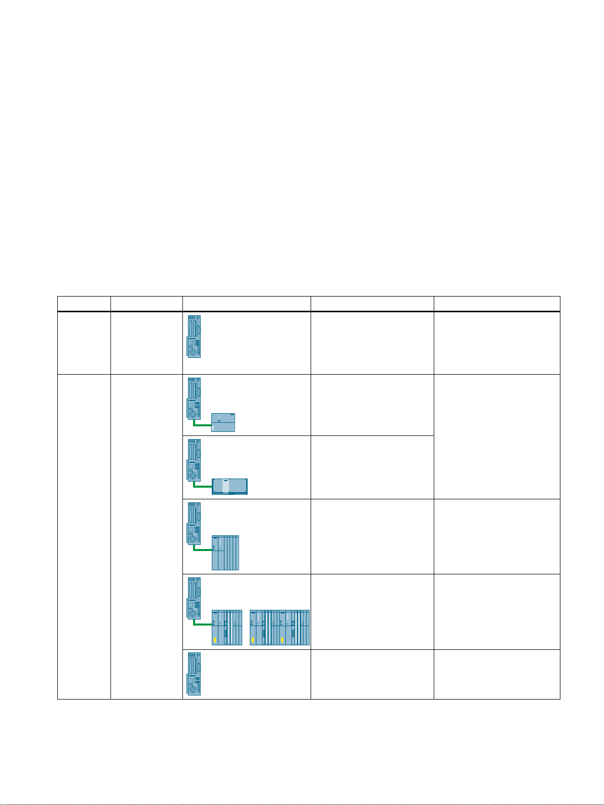
system, there are two versions of the SIMATIC PCS 7 BOX PC:
Variant Product name Picture Selection of the AS Description
AS integra‐
ted
AS not inte‐
grated
SIMATIC
PCS 7 BOX
RTX
SIMATIC
PCS 7 BOX
Integrated:
Software CPU
(WinAC RTX)
AS with S7-300 design /
SIMATIC PCS 7
AS mEC RTX
SIMATIC PCS 7 AS RTX
SIMATIC PCS 7 BOX RTX al‐
lows ES/OS or OS operation.
WinAC RTX 2010 supports
up to 2000 AS process ob‐
jects (PO).
SIMATIC PCS 7 BOX allows
ES/OS or OS operation.
WinAC RTX 2010 supports
up to 2000 AS process ob‐
jects (PO).
2
AS 41x of the series SIMAT‐
IC S7‑400
AS 41xH of the series SI‐
MATIC S7‑400H
(optionally with S7F system)
No AS SIMATIC PCS 7 BOX allows
BOX (V8.1)
Function Manual, 03/2015, A5E32711362-AC 9
SIMATIC PCS 7 BOX allows
ES/OS or OS operation.
The maximum AS configura‐
tion limit depends on the type
of AS 41x.
SIMATIC PCS 7 BOX allows
ES/OS or OS operation.
The maximum AS configura‐
tion limit depends on the type
of AS 41xH.
ES/OS or OS operation.
Page 10

Preface
Configuration options
SIMATIC PCS 7 BOX
RTX
ES/OS single station
with up to 2000 OS PO
OS single station with
up to 2000 OS PO
SIMATIC PDM possible possible possible possible
SIMATIC PCS 7 Main‐
tenance Station
SIMATIC BATCH up to
10 units
Web server, based on
Windows 7 for up to 2
Web clients
High-precision time
stamps
S7 F systems possible
SIMATIC Safety Matrix possible
possible possible possible possible
possible possible possible possible
possible possible possible possible
possible possible possible
possible possible possible
possible possible
SIMATIC PCS 7 BOX
with PCS 7
AS mEC RTX or with
PCS 7 AS RTX
SIMATIC PCS 7 BOX
with AS 41x
SIMATIC PCS 7 BOX
with AS 41xH
(can be ordered as
AS 400F)
Note
The SIMATIC PCS 7 BOX PC with integrated AS (SIMATIC PCS 7 BOX RTX) is described in
greater detail in this documentation.
Location of use
The SIMATIC PCS 7 BOX can be placed on-site where the automation process takes place,
because it is designed for these environmental conditions.
Required basic knowledge
This documentation is intended for personnel involved in configuring, commissioning, and
servicing.
Basic knowledge of the general use of the PC/programming device and of the use of the
Windows operating system is required. In addition to this, you should be familiar with the
functions and configurations of SIMATIC S7 (S7-400, STEP 7), SIMATIC NET and SIMATIC
PCS 7.
BOX (V8.1)
10 Function Manual, 03/2015, A5E32711362-AC
Page 11

Options for accessing PCS 7 documentation
You can find the PCS 7 documentation at the following locations:
Preface
● On the
● After installation, on the computer
● On the Internet
Full versions of the documentation are available from the "Technical Documentation SIMATIC
PCS 7" website: www.siemens.com/pcs7-documentation (www.siemens.com/pcs7-
documentation)
Note
PCS 7 Readme (Internet version)
The information provided in the
7 documentation.
Read this
enhancements to PCS 7.
PCS 7 documentation for the
● PCS 7 Readme (DVD version)
The
important information about PCS 7 and takes precedence over the PCS 7 documentation
supplied with the product. After installation of PCS 7, you can find the
System PCS 7; PCS 7 Readme
path:
Siemens Automation > SIMATIC > Product Notes > <language>
Process Control System; SIMATIC PCS 7
PCS 7 Readme
PCS 7 Readme
carefully; it contains important information and describes
in the Internet takes precedence over all PCS
Process Control System; SIMATIC PCS 7
PCS 7 Readme
on the
Process Control System; SIMATIC PCS 7
document in the Windows Start menu using the following
DVD
DVD
DVD contains
Process Control
● You will find the most important PCS 7 system documentation at the following locations:
– On the
– On the engineering station as online help (CHM file) for the SIMATIC Manager
application
– On the engineering station as a PDF file in the Windows Start menu using the following
path:
Siemens Automation > SIMATIC > Documentation > <language>
Note
The following PCS 7 system documentation is included:
● Catalog Overview
● Configuration manual
● Function manual
● Configuration manual
● Function manual
● The product documentation is installed with the relevant product.
SIMATIC PCS 7
Process Control System PCS 7; PCS 7 Documentation
Process Control System PCS 7; PCS 7 - PC Configuration
Process Control System PCS 7; OS Process Control
DVD in the "_Manuals" folder
Process Control System PCS 7; Engineering System
Process Control System PCS 7; Operator Station
BOX (V8.1)
Function Manual, 03/2015, A5E32711362-AC 11
Page 12

Preface
Documentation for PCS 7 on the Internet (current versions)
The latest documentation on the PCS 7 versions is available from the "Technical
Documentation SIMATIC PCS 7" website:
● In the section "Software manuals for SIMATIC PCS 7 ..."
– Links to the latest system and product documentation of the relevant PCS 7 version.
– Link for downloading the Setup for the latest system documentation
"PCS 7 Documentation Portal Setup".
Note
PCS 7 Documentation Portal Setup
Setup includes the complete system documentation for PCS 7 (PDF files and online
help).
● You can install this Setup without PCS 7.
● The following documentation is updated when you install the Setup on the
engineering station (completed and overwritten - if you select the original installation
folder):
– Online help of the "SIMATIC Manager" application: (CHM files)
– System documentation for PCS 7 in the Windows Start menu:
Siemens Automation > SIMATIC > Documentation > Language > PDF files
● The PCS 7 Newsletter keeps you informed when new versions of the system
documentation become available.
Conventions
– The link to download the entire PCS 7 documentation as a
Documentation Manager (http://support.industry.siemens.com/my/ww/en/
documentation/advanced/).
The
Manual Collection
● In the section "Hardware Manuals for SIMATIC PCS 7 ..."
– The link to the latest manuals for components approved for a PCS 7 version.
– The link to the latest manuals for approved SIMATIC PCS 7 industry software for PCS
7.
Catalogs, brochures, customer magazines and demo software
This information is available on the Internet at: Information and Download Center (http://
www.automation.siemens.com/mcms/infocenter)
In this documentation, the names of elements in the software interface are specified in the
language of this documentation. If you have installed a multi-language package for the
operating system, some of the designations will be displayed in the base language of the
operating system after a language switch and will, therefore, differ from the designations used
in the documentation.
includes the manuals for hardware and software.
Manual Collection
in the My
BOX (V8.1)
12 Function Manual, 03/2015, A5E32711362-AC
Page 13

Much of the information in this documentation applies to several components. To ensure that
the products to which such information applies are clearly identifiable, we have used the
following designations:
Designation Validity
SIMATIC PCS 7 BOX RTX The related information only applies to
SIMATIC PCS 7 BOX with S7‑mEC The related information only applies to
SIMATIC PCS 7 BOX with AS RTX The related information only applies to
SIMATIC PCS 7 BOX with S7-400 The corresponding information relates to
Changes compared to the previous version
Below, you can find an overview of the most important changes in the documentation compared
to the previous version:
Preface
SIMATIC PCS 7 BOX RTX.
SIMATIC PCS 7 AS mEC RTX.
SIMATIC PCS 7 AS RTX.
SIMATIC PCS 7 BOX in combination with SIMATIC AS 41x or
AS 41xH.
As of PCS 7 V8.0 SP1
● Additional BOX PCs are available.
As of PCS 7 V8.0 UPD 1
● SIMATIC PCS 7 AS mEC RTX: Distributed I/O at PROFINET IO possible.
As of PCS 7 V7.1 SP2
● In the case of configurations with integrated CPU based on WinAC RTX 2010 (V4.6), an
Additional information
● You can find additional information on the engineering system in the
● You can find additional information on the operator station in the
● You will find information about time synchronization in the
● You can find additional information on the maintenance station in the
● The SIMATIC PCS 7 BOX PC supports "Routing". You can information on this in the
integrated data record gateway enables direct access to field devices which are connected
by means of the integrated CP 5611 .
Process Control
System PCS 7; Engineering System
function manual.
Process Control System
PCS 7; Operator Station
function manual.
Process Control System PCS 7;
Time Synchronization
function manual.
Process Control
System PCS 7; Maintenance Station
SIMATIC; The Process Device Manager
function manual.
function manual.
BOX (V8.1)
Function Manual, 03/2015, A5E32711362-AC 13
Page 14

Preface
BOX (V8.1)
14 Function Manual, 03/2015, A5E32711362-AC
Page 15

Use and Areas of Application
3.1 Usage of SIMATIC PCS 7 BOX RTX
What is SIMATIC PCS 7 BOX RTX?
SIMATIC PCS 7 BOX RTX is a complete process control system which can consist of the
following components:
● Operator station (OS)
● Automation system WinAC RTX (internal AS)
● Distributed I/O
● Optional:
– Engineering station (ES) (depending on the configuration variant)
– SIMATIC PDM
SIMATIC PCS 7 BOX RTX enables you to cost-effectively build a complete process control
system with all necessary components and SIMATIC PCS 7 standard software.
3
Areas of application for SIMATIC PCS 7 BOX RTX
SIMATIC PCS 7 BOX RTX is suitable for the following areas of application:
● Autonomous small plants
● Subprocess units (package units) with an integrated operator control and monitoring unit
● Testing, educational and training systems
● Research facilities
Due to the full integration in SIMATIC PCS 7, you can enjoy all the benefits of the modern
SIMATIC PCS 7 process control system. Above all, this applies to the following applications:
● Externalizing the engineering station from SIMATIC PCS 7 BOX RTX and thereby
performing the engineering from an external engineering station
● Configuration of AS-AS communication using SIMATIC PCS 7 BOX RTX in the PCS 7
network
● Combination of local operator control and monitoring with SIMATIC PCS 7 BOX RTX and
centralized operator control and monitoring with PCS 7 OS in the control room
● SIMATIC PCS 7 BOX RTX is a cost-effective automation system for plants in which
configuration in run (CiR) is not required.
BOX (V8.1)
Function Manual, 03/2015, A5E32711362-AC 15
Page 16
'33$/LQN
352),%86'3
352),%863$
26
(6
3'0
6,0$7,&3&6%2;57;
6,0$7,&1(7
:LQ$&57;
9'&
(WKHUQHW
RQERDUG
(WKHUQHW
RQERDUG
&3
RQERDUG
Use and Areas of Application
3.1 Usage of SIMATIC PCS 7 BOX RTX
Bundle PC
SIMATIC PCS 7 BOX RTX Description Related sections in this manual
The hardware it is based on is a
Box PC.
The WinAC RTX software pack‐
age is installed with the SIMATIC
PCS 7 BOX RTX .
You connect the distributed I/O
via the PROFIBUS DP interface
CP 5611 integrated in SIMATIC
PCS 7 BOX RTX .
Example configuration with SIMATIC PCS 7 BOX RTX
In the figure below, the SIMATIC PCS 7 BOX RTX is displayed as the single-station system
variant with connected distributed I/O.
● Structure of SIMATIC PCS 7
BOX RTX (Page 27)
● Commissioning and
configuration of SIMATIC PCS 7
BOX RTX (Page 45)
BOX (V8.1)
16 Function Manual, 03/2015, A5E32711362-AC
Page 17

Use and Areas of Application
3.2 Using SIMATIC PCS 7 BOX with PCS 7 AS mEC RTX
3.2 Using SIMATIC PCS 7 BOX with PCS 7 AS mEC RTX
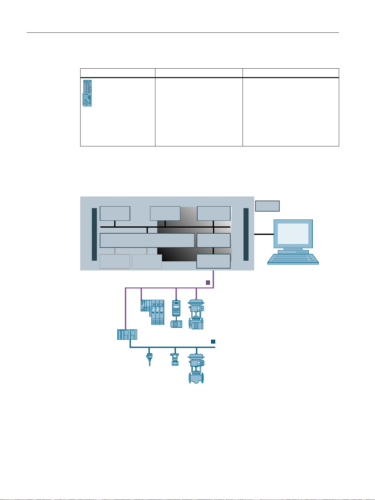
What is SIMATIC PCS 7 BOX with PCS 7 AS mEC RTX?
SIMATIC PCS 7 BOX with PCS 7 AS mEC RTX is a SIMATIC PCS 7 BOX PC in combination
with an automation system (AS) with S7-300 design. The WinACRTX software package is
installed on the PCS 7 AS mEC RTX. This enables you to realize a complete PCS 7 process
control system with the following components:
● Operator station (OS)
● Automation system PCS 7 AS mEC RTX(separate AS)
● Centralized I/O
● Distributed I/O
● Optional: Engineering station (ES) (depending on the configuration variant)
Areas of application for SIMATIC PCS 7 BOX with PCS 7 AS mEC RTX
SIMATIC PCS 7 BOX with PCS 7 AS mEC RTX is suitable for the following areas of application:
Bundle PC
● Autonomous small plants
● Subprocess units (package units) with an integrated operator control and monitoring unit
● Testing, educational and training systems
● Research facilities
● Plants in which configuration in run (CiR) is not required.
SIMATIC PCS 7 BOX with
PCS 7 AS mEC RTX
AS model Related sections in this manual
SIMATIC PCS 7 BOX with
PCS 7 AS mEC RTX features the Wi‐
nAC RTX software package.
BOX (V8.1)
Function Manual, 03/2015, A5E32711362-AC 17
Page 18
(QJLQHHULQJ6WDWLRQ
2SHUDWLQJV\VWHP
:LQ$&57;
36
60
60
60
(03&
(70
352),%86'3
352),%863$
6,0$7,&3&66P(&
,(3%/LQN
,(3%/LQN)'&
Use and Areas of Application
3.2 Using SIMATIC PCS 7 BOX with PCS 7 AS mEC RTX
Example configuration with PCS 7 AS mEC RTX
A schematic representation of the SIMATIC PCS 7 BOX with PCS 7 AS mEC RTX is provided
in the following figure:
Additional information
You can connect signals via the central I/O or distributed I/O:
● Up to 8 signal modules of the S7-300 type series can be connected as central I/O.
● Connection of PROFINET IO distributed I/O via the communication processor CP 1616
You can find more information in the "S7‑300" section of the
Catalog Overview; Released Modules
Operating instructions
Embedded Automation; S7-modular Embedded Controller
documentation.
Process Control System PCS 7
BOX (V8.1)
18 Function Manual, 03/2015, A5E32711362-AC
Page 19

3.3 Using SIMATIC PCS 7 BOX with AS RTX
3.3 Using SIMATIC PCS 7 BOX with AS RTX
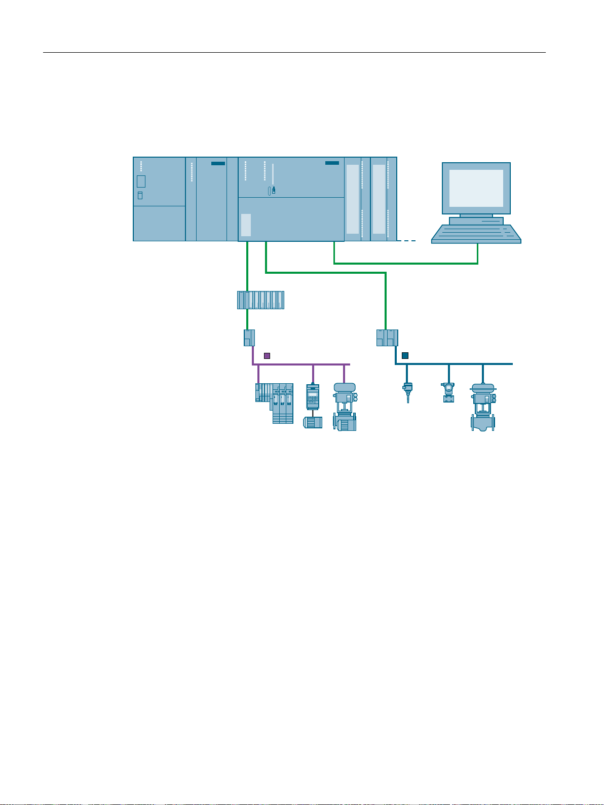
What is SIMATIC PCS 7 BOX with AS RTX?
SIMATIC PCS 7 BOX with AS RTX is a SIMATIC PCS 7 BOX PC in combination with the
WinAC RTX software package on a MICROBOX PC. This enables you to build a complete
PCS 7 process control system with the following components:
● Operator station (OS)
● Automation system SIMATIC PCS 7 AS RTX (separate AS)
● Distributed I/O
● Optional: Engineering station (ES) (depending on the configuration variant)
Areas of application for SIMATIC PCS 7 BOX with AS RTX
SIMATIC PCS 7 BOX with AS RTX is suitable for the following areas of application:
● Autonomous small plants
Use and Areas of Application
Bundle PC
● Subprocess units (package units) with an integrated operator control and monitoring unit
● Testing, educational and training systems
● Research facilities
● Plants in which configuration in run (CiR) is not required.
SIMATIC PCS 7 BOX with
AS RTX
AS model Related sections in this manual
SIMATIC PCS 7 BOX with AS RTX
features the WinAC RTX software
package.
You connect the distributed I/O via the
CP 5611 PROFIBUS DP interface in‐
tegrated in the MICROBOX PC.
● Installation of SIMATIC
PCS 7 AS mEC RTX
(Page 87)
● Commissioning and
configuring SIMATIC PCS 7
AS mEC RTX (Page 95)
BOX (V8.1)
Function Manual, 03/2015, A5E32711362-AC 19
Page 20
(QJLQHHULQJVWDWLRQ
2SHUDWLQJV\VWHP
:LQ$&57;
'33$/LQN
352),%86'3
352),%863$
9'&
(WKHUQHW
RQERDUG
6,0$7,&1(7
86%
(WKHUQHW
RQERDUG
&3
RQERDUG
86%
6,0$7,&0,&52%2;3&
Use and Areas of Application
3.4 Using SIMATIC PCS 7 BOX with S7-400
Example configuration with SIMATIC PCS 7 BOX
A schematic representation of the SIMATIC PCS 7 BOX with AS RTX is provided in the
following figure:
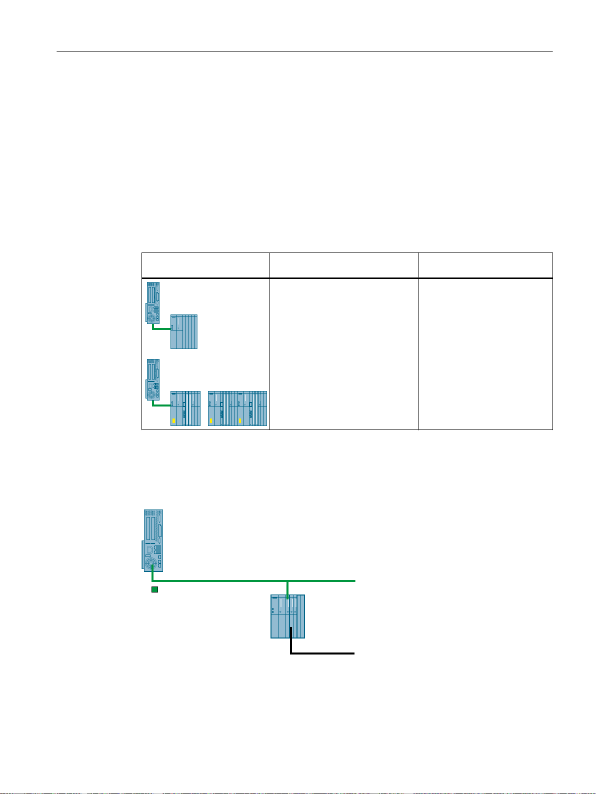
3.4 Using SIMATIC PCS 7 BOX with S7-400
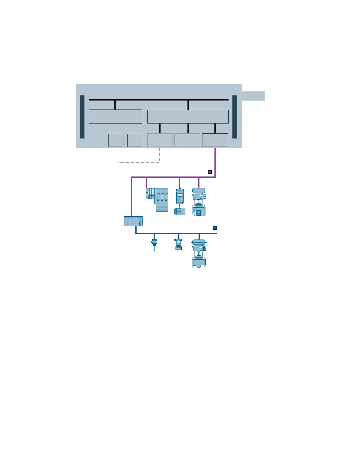
What is SIMATIC PCS 7 BOX with S7-400?
SIMATIC PCS 7 BOX with S7-400 is an automation system SIMATIC S7-400 (AS 41x or AS
41xH) in combination with a SIMATIC PCS 7 BOX PC. This enables you to build a complete
PCS 7 process control system with the following components:
● Operator station (OS)
● Automation system of the SIMATIC S7-400 series (separate AS)
● Distributed I/O
● Optional: Engineering station (ES) (depending on the configuration variant)
20 Function Manual, 03/2015, A5E32711362-AC
BOX (V8.1)
Page 21
Areas of application for SIMATIC PCS 7 BOX with S7-400
6LQJOHVWDWLRQV\VWHP26
)LHOGEXV
6,0$7,&6
3ODQWEXV,QGXVWULDO(WKHUQHW
SIMATIC PCS 7 BOX with S7-400 is suitable for the following areas of application:
● Autonomous small plants
● Subprocess units (package units) with an integrated operator control and monitoring unit
● Testing, educational and training systems
● Research facilities
● Plants in which configuration in run (CiR) is required.
Bundle PC
Use and Areas of Application
3.4 Using SIMATIC PCS 7 BOX with S7-400
SIMATIC PCS 7 BOX with
S7‑400
AS model Additional information
SIMATIC PCS 7 BOX with S7-400
features a SIMATIC AS 41x or
AS 41xH.
You connect the distributed I/O to
the AS.
Example configuration with SIMATIC PCS 7 BOX with S7‑400
The following figure shows SIMATIC PCS 7 BOX with S7-400 in the network with an
engineering station:
● Section " Optional modules
(Page 32)"
● Configuration manual
Process Control System
PCS 7; Engineering System
● Manual Process Control
System PCS 7;
Faulttolerant Process Control
Systems.
BOX (V8.1)
Function Manual, 03/2015, A5E32711362-AC 21
Page 22

Use and Areas of Application
3.4 Using SIMATIC PCS 7 BOX with S7-400
Additional information
The "High-precision time stamping" function can be used with SIMATIC PCS 7 BOX with
AS 41x. You can find information about this in the function manual
PCS 7; High-precision time stamping
Process Control System
.
BOX (V8.1)
22 Function Manual, 03/2015, A5E32711362-AC
Page 23

WinAC RTX
What is WinAC RTX?
WinAC RTX is a software package for a PC-based automation system. This software package
contains the Windows Logic Controller RTX (software PLC WinLC RTX).
Connection of I/O
WinAC RTX can control distributed I/O both via PROFIBUS and via PROFINET .
By means of an integrated data record gateway, WinAC RTX 2010 (V4.6) enables direct
access to field devices that are connected via a communication processor at the fieldbus.
The isochronous mode system function is supported. This feature enables you to realize fast,
time-dependent applications, for example, closed loop controls, with distributed I/O.
PCS 7 Advanced Process Library with WinAC RTX
The following setting is required for all relevant block types (see Additional information) when
using the "PCS 7 Advanced Process Library (APL)":
For each block instance of one of these block types used in the application, bit number 22
should be preset with "1" at the "Feature" I/O.
4
Additional information
● You can find additional information on the relevant APL block types in the PCS 7 Advanced
● Manual
Process Library online help in the following section:
Basics of APL > Selectable block response > Functions that can be set via the "Feature" I/
O > Configurable functions with the Feature I/O >
Bit "Number 22" ("Update acknowledgment and error status of the message call")
SIMATIC; Windows Automation Center RTX; WinAC RTX 2010
BOX (V8.1)
Function Manual, 03/2015, A5E32711362-AC 23
Page 24

WinAC RTX
BOX (V8.1)
24 Function Manual, 03/2015, A5E32711362-AC
Page 25
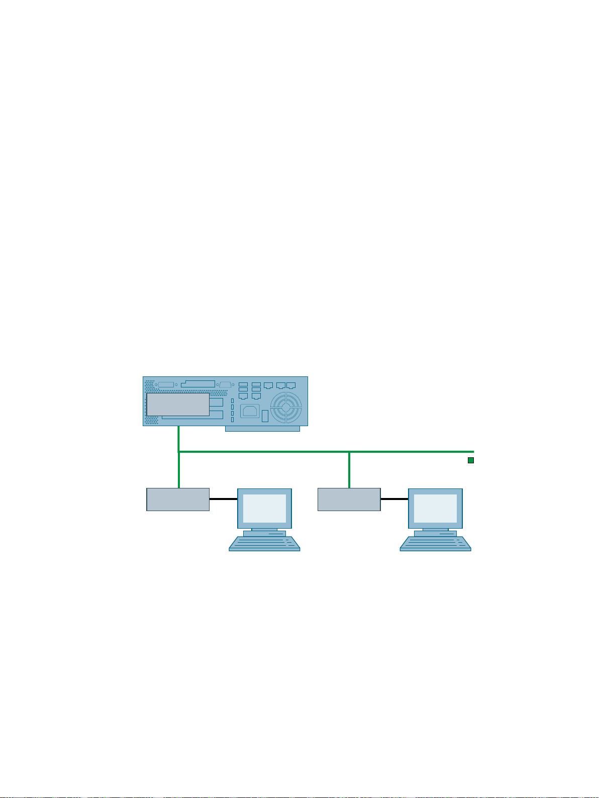
Web Option for OS with SIMATIC PCS 7 BOX
:HE26
3ODQWEXV
:HE&OLHQW:HE&OLHQW
6,0$7,&3&6%2;3&
$6
:HE&OLHQW
$6
:HE&OLHQW
:HE26
Web Option für OS
The Web Option for OS can be used with SIMATIC PCS 7 BOX PCs. Note the following:
● A SIMATIC PCS 7 BOX PC with separate, external automation system is suitable as Web
server for up to 2 Web clients.
● A SIMATIC PCS 7 BOX PC can be used as Web client.
Exception: The version SIMATIC PCS 7 BOX RTX has not been released for this.
Information on the engineering and configuration of Web servers and Web clients is available
in the
Process Control System PCS 7; OS Web Option
Number of Web clients
A maximum of 2 Web clients can connect to a Web server which is installed on the SIMATIC
PCS 7 BOX PC. The following figure shows the Web Option for OS with SIMATIC PCS 7 BOX
PC:
function manual.
5
License keys
Additional information
BOX (V8.1)
Function Manual, 03/2015, A5E32711362-AC 25
You can find information on the required license keys in the documentation
System PCS 7; Licenses and Configuration Limits
● Manual
SIMATIC; SIMATIC BATCH
.
Process Control
Page 26

Web Option for OS with SIMATIC PCS 7 BOX
BOX (V8.1)
26 Function Manual, 03/2015, A5E32711362-AC
Page 27

Structure of SIMATIC PCS 7 BOX RTX
6.1 Introduction
Introduction
The following sections contain the configuration options and general information on the
configuration of SIMATIC PCS 7 BOX RTX.
The characteristics of the process control system correspond to the standard of SIMATIC
PCS 7. The characteristics of the CPU correspond to the controller used.
Overview
The following topics are discussed in the sections below:
● Hardware and software components of SIMATIC PCS 7 BOX RTX
● Configurations with SIMATIC PCS 7 BOX RTX
● Connection options for SIMATIC PCS 7 BOX RTX
● Operator panel of the CPU
6
Ordering information
● The order information is listed in the
Additional information
● Section "Functional compatibility with SIMATIC PCS 7 (Page 32)"
● Configuration manual
● Configuration manual
● Manual
● Manual
● Manual
ST PCS 7
Process Control System PCS 7; Engineering System
Process Control System PCS 7; Operator Station
SIMATIC; Windows Automation Center RTX; WinAC RTX 2010
SIMATIC; The Process Device Manager
SIMATIC; Automation License Manager
catalog.
BOX (V8.1)
Function Manual, 03/2015, A5E32711362-AC 27
Page 28

Structure of SIMATIC PCS 7 BOX RTX
6.2 Hardware and software components of SIMATIC PCS 7 BOX RTX
6.2 Hardware and software components of SIMATIC PCS 7 BOX RTX
6.2.1 Hardware components
Introduction
SIMATIC PCS 7 BOX RTX is offered as a bundle with standard hardware.
Technical features of the SIMATIC PCS 7 BOX PCs
You can find the technical features of the respective shipped versions of these PCs in the
PCS 7
catalog. This includes the following information:
● General features (processor, work memory/main memory, free expansion slots, graphics
controller)
● Drives (hard disks, DVD)
● Interfaces (Ethernet, PROFIBUS DP, automation system (CPU) and serial interfaces,
interfaces for mouse, keyboard and printer)
The PCs have 2 integrated Ethernet interfaces. These integrated Ethernet interfaces are
preconfigured for the appropriate bus systems (terminal or plant bus). The product
information provided with the PCs describes which Ethernet interface is configured for any
given bus system.
Optional expansion of the product bundle
You can expand the product bundle to include the following add-on components:
● SITOP modular 20 A (power supply)
● SITOP DC UPS module
● Multi-monitor graphics cards and process monitors (design variant with front panel (TFT
Touch Panel) )
● Mouse and keyboard (German or international keyboard layout)
ST
● Smart card reader
● Signal module
You can find additional information on this topic in the section "Optional modules
(Page 32)".
● Communication adapter for different versions of the system bus communication
You can find additional information on this in the section "Optional modules (Page 32)"
● Additional PROFIBUS connection with CP 5613 A2
You can find additional information on this in the section "Optional modules (Page 32)"
BOX (V8.1)
28 Function Manual, 03/2015, A5E32711362-AC
Page 29

Additional information
Structure of SIMATIC PCS 7 BOX RTX
6.2 Hardware and software components of SIMATIC PCS 7 BOX RTX
● Product information
● Catalog
● Catalog
● Documentation
ST PCS 7
PC-based Automation
SIMATIC PCS 7 BOX
, section "SIMATIC PCS 7 BOX"
pcs7-readme
6.2.2 Software components
Configuration variants (product bundles)
SIMATIC PCS 7 BOX RTX is available as a bundled product in two preinstalled configuration
variants.
● Configuration variant 1:
SIMATIC PCS 7 complete system with AS, ES and OS functionality:
– CPU as the software version
– Engineering station
– OS single-station system
● Configuration variant 2:
SIMATIC PCS 7 runtime system with AS and OS functionality:
– CPU as the software version
– OS single-station system
You configure the PCS 7 system with an external engineering station (not included in the
product bundle).
Pre-installed software components on SIMATIC PCS 7 BOX RTX
The following components are preinstalled on the SIMATIC PCS 7 BOX RTX:
● Windows operating system, Internet Explorer and MS SQL Server
● Selected software components of the DVD
● Software package WinAC RTX
Process Control System; SIMATIC PCS 7
BOX (V8.1)
Function Manual, 03/2015, A5E32711362-AC 29
Page 30

Structure of SIMATIC PCS 7 BOX RTX
6.2 Hardware and software components of SIMATIC PCS 7 BOX RTX
License keys in the SIMATIC PCS 7 BOX RTX scope of delivery
Note
A SIMATIC PCS 7 license grants the user permission to use the products. This permission is
granted in the form of:
● CoL (Certificate of License) - a legal proof of the ownership fir a copyrighted software
product of SIMATIC PCS 7.
● License key (authorization code) - technical representation of the license.
Note
You can find information on the license keys required for an OS single-station system or for
an engineering station in the following documents:
● Documentation
● Documentation
The license keys in the standard scope of delivery of SIMATIC PCS 7 BOX RTX limit the plant
size that can be configured. You require several license keys for a SIMATIC PCS 7 BOX
station.
Process Control System PCS 7; PC Configuration
Process Control System PCS 7;
Licenses and Configuration Limits
Components requiring a license
key
Software for the CPU
PCS 7 Engineering & PCS 7 OS OS RT PO (CR: 250, SL)
PCS 7 OS OS RT PO (CR: 250, SL)
PCS 7 AS Runtime AS RT PO (250)
Activating the software components
In order to use the software components, valid license keys must be located on the SIMATIC
PCS 7 BOX PC. The license keys are supplied on a license key USB stick. You can transfer
the license keys to the SIMATIC PCS 7 BOX PC using the Automation License Manager.
You can find additional information about transferring license keys in the
Automation License Manager
Settings for energy options
License keys for
SIMATIC PCS 7 BOX RTX
Configuration variant 1: Configuration variant 2:
● WinAC; WinAC RTX
● SIMATIC PCS 7; RTX
● SIMATIC NET; Industrial Ethernet SOFTNET-S7 Basic
(plant size up to 250 PO)
(plant size up to 250 PO)
online help for the
.
The preset "SIMATIC" or "SIMATIC IPC" energy scheme may not be changed. The settings
in this energy scheme are optimized for running the software PLC with the IntervalZero RTX
real-time environment.
BOX (V8.1)
30 Function Manual, 03/2015, A5E32711362-AC
Page 31

6.2 Hardware and software components of SIMATIC PCS 7 BOX RTX
Optional expansion of the product bundles
The product bundles can be further expanded:
● SIMATIC PCS 7 PowerPacks for visualizing up to 2,000 PO
(OS RT PO (CR: 2000, SL) )
● SIMATIC PCS 7 PowerPacks for configuring the PCS 7 plant
● SIMATIC PDM package for PCS 7: starter package with 128 devices; expandable
● PCS 7 Maintenance Station (Asset Management): Full functionality for "SIMATIC
PCS 7 BOX" and subordinate systems
The following options are available in a PCS 7 plant for a SIMATIC PCS 7 BOX when a
maintenance station is used:
– SIMATIC PCS 7 BOX is monitored by a maintenance station in the PCS 7 plant
– SIMATIC PCS 7 BOX is the maintenance station and monitors itself and downstream
systems (modules and field devices that are connected to SIMATIC PCS 7 BOX)
Note
No diagnostics are possible for components in the PCS 7 network that do not belong to
this SIMATIC PCS 7 BOX station.
Structure of SIMATIC PCS 7 BOX RTX
UPS software for further processing of UPS signals on a PC.
Note
You can find the ordering information for additional PCS 7 software in the
Supplied data media
The following data media is supplied with SIMATIC PCS 7 BOX RTX:
● License key USB stick
● Data medium for restoring the factory state (Page 125)
Additional information
●
● Documentation
● Product information
ST PCS 7
catalog
pcs7-readme
SIMATIC; SIMATIC PCS 7 BOX RTX
ST PCS 7
catalog.
BOX (V8.1)
Function Manual, 03/2015, A5E32711362-AC 31
Page 32

Structure of SIMATIC PCS 7 BOX RTX
6.2 Hardware and software components of SIMATIC PCS 7 BOX RTX
6.2.3 Compatibility to SIMATIC PCS 7
Functional compatibility with SIMATIC PCS 7
SIMATIC PCS 7 BOX RTX is compatible with SIMATIC PCS 7 and offers the following range
of functions:
● SIMATIC PCS 7 BOX RTX provides the functionality of a standard CPU, an OS single
station (without redundancy) and an engineering station (optional).
● The CPU can communicate with another AS via communication blocks (interconnected in
the CFC ) and can physically communicate via the Industrial Ethernet interface integrated
in the SIMATIC PCS 7 BOX RTX.
● The CPU can communicate with an OS server via the Industrial Ethernet interface
integrated in the SIMATIC PCS 7 BOX RTX.
● The "Compile and download objects" function in SIMATIC Manager can be used for the
configured CPU.
● The clock synchronization of the OS and AS within the SIMATIC PCS 7 BOX PC is
performed via a central clock (clock master) on the plant bus or via the local PC clock of
the SIMATIC PCS 7 BOX PC. You can set the time synchronization of the AS using the
"WinAC Time Synchronization" function.
● Diagnostics software is included on the bundle PC so that diagnostics can be performed
for the SIMATIC PCS 7 BOX PC functions.
You can find additional information in the manual titled
Software Update with Utilization of New Functions.
Properties of SIMATIC PCS 7 BOX
● Configuration: The CPU is listed in HW Config in the catalog under SIMATIC PC Station
\Controller\... .
● Remote engineering and remote diagnostics via Industrial Ethernet:
The CPU of the SIMATIC PCS 7 BOX can be loaded and diagnosed by a PCS 7 engineering
station which is connected via the Ethernet interface integrated in the SIMATIC PCS 7 BOX
PC.
6.2.4 Optional modules
Additional PROFIBUS connection
The CP 5613 A2 communication processor is a PCI module for connecting PROFIBUS to a
computer. This module is more powerful than the CP 5611 communication processor
integrated in the BOX PC.
Process Control System PCS 7;
BOX (V8.1)
32 Function Manual, 03/2015, A5E32711362-AC
Page 33

Connection of automation systems
You can use the following network adapters to connect to the system bus:
● Standard communication modules:
– If you are connecting up to 8 communication partners per PC station (automation
systems or servers).
– If you are using fault-tolerant automation systems with CPUs (firmware version as of
V6.0).
● Communication modules with on-board processors (CP 16xx) are required in the following
cases:
– If you are connecting between 9 and a maximum of 64 communication partners per PC
station (automation systems or servers).
– If fault-tolerant automation systems are used with CPUs (firmware version earlier than
V6.0).
– If you require connections between a PC station with 2 network adapters to fault-tolerant
automation systems.
Structure of SIMATIC PCS 7 BOX RTX
6.2 Hardware and software components of SIMATIC PCS 7 BOX RTX
Connecting multiple monitors via DVI
If you want to connect several monitors to one PC station, please note the following:
● You can connect one monitor to one port.
● If you want to connect the monitors via DVI, you will need an active adapter (Active
DisplayPort (M) to Single-Link DVI (F) ) as of the third monitor.
Signal module
When a BOX-PC is used as an OS single-station system or as an OS client, a signal module
can be added to the PC. These signal modules can control a horn and up to 3 different lamps
or buzzer tones that represent a variety of message classes. Using a hardware timer
(watchdog), the signal modules can detect and signal the failure of an operator station. A
hardware acknowledgment button can also be connected.
A PCI slot has to be free in the PC for the signal module.
Additional information
Note
Product notes for the bundle PC
Please observe the product notes for the bundle PC. They include additional information on
the drivers for various components and operating systems.
● ST PCS 7 catalog
● Function manual
BOX (V8.1)
Function Manual, 03/2015, A5E32711362-AC 33
Process Control System PCS 7; PCS 7 - PC Configuration
Page 34

Structure of SIMATIC PCS 7 BOX RTX
6.3 Configurations with SIMATIC PCS 7 BOX RTX
● You can find approved network adapters in the Catalog Overview
PCS 7; Released Modules
● You can find information on fault-tolerant automation systems in the function manual
Process Control System PCS 7; Fault-Tolerant Process Control Systems
● You will find information about time synchronization in the
Time Synchronization
function manual.
6.3 Configurations with SIMATIC PCS 7 BOX RTX
6.3.1 Configuration options
Configuration options
The following configurations are possible with SIMATIC PCS 7 BOX RTX based on the product
bundles available for order:
● Bundle: SIMATIC PCS 7 BOX RTX as SIMATIC PCS 7 complete system with AS, ES and
OS functionality:
– SIMATIC PCS 7 BOX as a single-station system (Page 35) with AS/ES/OS
Process Control System
.
Process Control System PCS 7;
● Bundle: SIMATIC PCS 7 BOX RTX as SIMATIC PCS 7 runtime system with AS and OS
functionality:
– SIMATIC PCS 7 BOX as AS/OS with external engineering (Page 36)
– SIMATIC PCS 7 BOX as AS/OS in a PCS 7 network (Page 38)
Note
The configuration options apply to an OS single-station system.
SIMATIC PCS 7 BOX RTX cannot be used as an OS client or OS server.
Expanded functions with additional software packages
You can install additional software packages from the "
7
" DVD.
You need the corresponding license key to use these software packages. You can find
additional information on this in the manual
Configuration
.
Additional information
● Manual
Process Control System PCS 7; PCS 7 - PC Configuration
Process Control System; SIMATIC PCS
Process Control System PCS 7; PCS 7 - PC
BOX (V8.1)
34 Function Manual, 03/2015, A5E32711362-AC
Page 35

'33$/LQN
352),%86'3
352),%863$
26
(6
3'0
6,0$7,&3&6%2;57;
6,0$7,&1(7
:LQ$&57;
9'&
(WKHUQHW
RQERDUG
(WKHUQHW
RQERDUG
&3
RQERDUG
6.3 Configurations with SIMATIC PCS 7 BOX RTX
6.3.2 SIMATIC PCS 7 BOX as a single-station system
SIMATIC PCS 7 BOX as a single-station system
In this configuration, you use SIMATIC PCS 7 BOX (complete system with ES/OS/AS) as a
single-station system.
The WinAC RTX software package is installed with SIMATIC PCS 7 BOX RTX for the
automation function. You connect the distributed I/O via the integrated PROFIBUS DP
interface, CP 5611.
Example with SIMATIC PCS 7 BOX RTX
In the figure below, SIMATIC PCS 7 BOX RTX (complete system with ES/OS/AS) is shown
as a single-station system with connected distributed I/O.
Structure of SIMATIC PCS 7 BOX RTX
License keys
You need license keys for the following software packages on the SIMATIC PCS 7 BOX PC:
● ES (engineering)
● PCS 7 OS (process mode)
● WinAC; WinAC RTX
BOX (V8.1)
Function Manual, 03/2015, A5E32711362-AC 35
Page 36

Structure of SIMATIC PCS 7 BOX RTX
6.3 Configurations with SIMATIC PCS 7 BOX RTX
● SIMATIC PCS 7; RTX
● SIMATIC NET; SIMATIC NET BCE
Note
The license keys for the optional add-on product bundles (such as SIMATIC PDM) must
be ordered separately.
Operating principle
From the point of view of the PCS 7 project, the SIMATIC PCS 7 BOX station (with integrated
CPU [AS]) is not networked. You create and maintain your PCS 7 project on this station and
download the PCS 7 project from the ES to the OS and CPU. The program created with
SIMATIC PCS 7 runs in process mode on the OS and CPU.
You can use the Process Device Manager (PDM) to access a PROFIBUS DP line and its
stations/devices via the special on-board CP 5611 interface. You can access the CPU in
SIMATIC Manager. Communication between the CPU and the integrated PROFIBUS DP
interface is performed internally in the PC.
Properties of SIMATIC PCS 7 BOX RTX
The time synchronization of the OS and the CPU in this configuration is performed using WinAC
time synchronization with the local PC clock only, if no externally connected clock is included.
Interface properties
You can find additional information on this in the section "Connection to PROFIBUS DP
(Page 41)".
6.3.3 SIMATIC PCS 7 BOX with external engineering
SIMATIC PCS 7 BOX RTX for process mode with external engineering
In this configuration, you use SIMATIC PCS 7 BOX RTX (SIMATIC PCS 7 runtime system with
AS and OS functions) exclusively for process mode.
The SIMATIC PCS 7 BOX PC includes an AS/OS single-station system without license keys
for engineering. In this case, configure the SIMATIC PCS 7 BOX station from an engineering
station external to the SIMATIC PCS 7 BOX PC. You have to download the engineering data
to the CPU integrated in the SIMATIC PCS 7 BOX RTX. You have to download the visualization
data to the PCS 7 OS integrated in the SIMATIC PCS 7 BOX PC.
BOX (V8.1)
36 Function Manual, 03/2015, A5E32711362-AC
Page 37

Example with SIMATIC PCS 7 BOX RTX
6,0$7,&6
'33$/LQN
352),%86'3
352),%863$
26
(6
3'0
6,0$7,&3&6%2;57;
6,0$7,&1(7
:LQ$&57;
9'&
(WKHUQHW
RQERDUG
(WKHUQHW
RQERDUG
&3
RQERDUG
%XVGHOLQVWDOODWLRQGXWHUPLQDOFRPELQ«7&3,3
The following figure represents a SIMATIC PCS 7 BOX RTX (SIMATIC PCS 7 runtime system
with AS and OS functions):
● With connected distributed I/O and external engineering
● With a shared bus system for the terminal bus and plant bus
Structure of SIMATIC PCS 7 BOX RTX
6.3 Configurations with SIMATIC PCS 7 BOX RTX
License keys
You need license keys for the following software packages on the SIMATIC PCS 7 BOX PC:
● PCS 7 OS
● WinAC; WinAC RTX
BOX (V8.1)
Function Manual, 03/2015, A5E32711362-AC 37
Page 38

Structure of SIMATIC PCS 7 BOX RTX
6.3 Configurations with SIMATIC PCS 7 BOX RTX
● SIMATIC PCS 7; RTX
● SIMATIC NET; SIMATIC NET BCE
Note
You need to separately order the license keys for the optional add-on product bundles (such
as SIMATIC PDM).
Operating principle
The external engineering station is networked with the SIMATIC PCS 7 BOX station. The
SIMATIC PCS 7 BOX PC is connected to the external engineering station via one of the two
on-board Ethernet interfaces. You use this connection to load the SIMATIC PCS 7 BOX station
(AS and OS). You can use the "Download Changes of OS" function in this configuration.
Properties of SIMATIC PCS 7 BOX RTX
The time synchronization of the OS and the CPU in this configuration is performed using WinAC
time synchronization with the local PC clock only, if no externally connected clock is included.
Interface properties
You can find information about this in the following sections:
● Section "Connection to PROFIBUS DP (Page 41)"
● Section "Network connection to Industrial Ethernet (Page 42)"
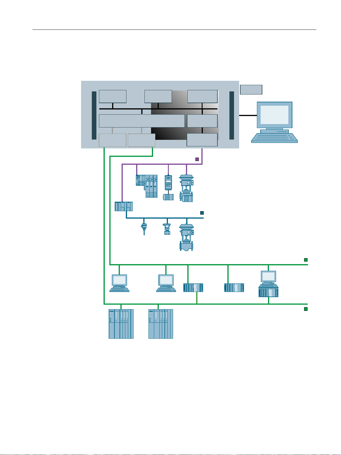
6.3.4 SIMATIC PCS 7 BOX in the PCS 7 network
SIMATIC PCS 7 BOX RTX for process mode in the PCS 7 network
In this configuration, you integrate the SIMATIC PCS 7 BOX station in a PCS 7 network as a
PC station with OS/AS. Here, in contrast to the "SIMATIC PCS 7 BOX with external
engineering (Page 36)" configuration, you need two network connections – from the SIMATIC
PCS 7 BOX station to the terminal bus and to the plant bus. In this configuration, you can
synchronize the time of day of the CPU using a time master connected to the plant bus.
BOX (V8.1)
38 Function Manual, 03/2015, A5E32711362-AC
Page 39
Example with SIMATIC PCS 7 BOX RTX
(QJLQHHULQJ
VWDWLRQ
06FOLHQW
3ODQWEXV
7HUPLQDOEXV
'33$/LQN
352),%86'3
352),%863$
9'&
26
(6
3'0
6,0$7,&3&6%2;57;
6,0$7,&1(7
:LQ$&57;
(WKHUQHW
RQERDUG
(WKHUQHW
RQERDUG
&3
RQERDUG
26VHUYHU06VHUYHU26FOLHQWV
6,0$7,&6
The following figure shows the SIMATIC PCS 7 BOX RTX with connected distributed I/O in
the PCS 7 network.
Structure of SIMATIC PCS 7 BOX RTX
6.3 Configurations with SIMATIC PCS 7 BOX RTX
License keys
You need license keys for the following software packages on the SIMATIC PCS 7 BOX PC:
● PCS 7 OS
● WinAC; WinAC RTX
BOX (V8.1)
Function Manual, 03/2015, A5E32711362-AC 39
Page 40

Structure of SIMATIC PCS 7 BOX RTX
6.3 Configurations with SIMATIC PCS 7 BOX RTX
● SIMATIC PCS 7; RTX
● SIMATIC NET BCE
Note
You need to separately order the license keys for the optional add-on product bundles (such
as SIMATIC PDM).
Operating principle
One of the two on-board Ethernet interfaces on the SIMATIC PCS 7 BOX station is connected
to the plant bus of the PCS 7 network. You download the user program via this connection
path from a central engineering station in the PCS 7 network to the CPU of the SIMATIC PCS 7
BOX station.
You connect the other on-board Ethernet interface on the SIMATIC PCS 7 BOX station to the
terminal bus. Via this connection path, you download the OS from a central engineering station
to the PCS 7 network.
You can use these two connection paths to create and maintain the program using the external
engineering station.
Properties of SIMATIC PCS 7 BOX RTX
● The Ethernet interface to the plant bus and terminal bus are set by default. You can find
the default addresses in the product information for the BOX PC.
● Communication (AS to AS) from an AS in the PCS 7 network to the CPU in the SIMATIC
PCS 7 BOX station can be performed with the WinAC RTX software package.
● No provision is made for communication between the OS in the SIMATIC PCS 7 BOX
station and an OS server in the PCS 7 network.
● No provision is made for operation with OpenPCS 7.
Interface properties
You can find information about this in the following sections:
● Section "Connection to PROFIBUS DP (Page 41)"
● Section "Network connection to Industrial Ethernet (Page 42)"
BOX (V8.1)
40 Function Manual, 03/2015, A5E32711362-AC
Page 41

Structure of SIMATIC PCS 7 BOX RTX
6.4 Connection options for SIMATIC PCS 7 BOX RTX
6.4 Connection options for SIMATIC PCS 7 BOX RTX
6.4.1 Connection to PROFIBUS DP
PROFIBUS DP
Use the PROFIBUS DP interface of the CP 5611 to connect the distributed I/O.
Properties of the PROFIBUS DP interfaces with SIMATIC PCS 7 BOX RTX
Interface Property
CP 5611 interface on board The CP 5611 communication processor has a full PROFIBUS DP
interface.
You can connect all the I/O devices permitted in SIMATIC PCS 7.
Example for using the PROFIBUS DP interfaces
The connection routes for the SIMATIC PCS 7 BOX RTX are shown in chapter "Configurations
with SIMATIC PCS 7 BOX RTX (Page 34)".
PROFIBUS PA
A DP/PA link with a DP/PA coupler is used to connect the PROFIBUS PA to a PROFIBUS DP .
You connect the intelligent field devices to the PROFIBUS PA.
Additional information
● Section "Connection of intelligent field devices (Page 41)"
● Section "Network connection to Industrial Ethernet (Page 42)"
6.4.2 Connection of intelligent field devices
A DP/PA link with a DP/PA coupler is used to connect the PROFIBUS PA to a PROFIBUS DP.
You connect the intelligent field devices to the PROFIBUS PA.
You assign parameters for the intelligent field devices using the Process Device Manager
(SIMATIC PDM).
Note
Use fiber-optic cables for the PROFIBUS connection to assign parameters using SIMATIC
PDM, if you require long cable lengths or high transmission rates.
BOX (V8.1)
Function Manual, 03/2015, A5E32711362-AC 41
Page 42

Structure of SIMATIC PCS 7 BOX RTX
6.4 Connection options for SIMATIC PCS 7 BOX RTX
Setting an access point
With PCS 7, you must set the "S7ONLINE (STEP 7)" access point in the "Set PG/PC Interface"
dialog box in accordance with how it is to be used. In the dropdown list "Assigned interface
parameter assignment", select the protocol of the interface to the plant bus ("IE General"):
● ‑"ISO Ind.Ethernet -> …"
● ‑"TCP/IP -> …"
Additional information
● Configuration manual
Process Control System PCS 7; Engineering System
● You will find a list of the connecting cables required for SIMATIC PCS 7 BOX in the
ST PCS 7
catalog.
6.4.3 Network connection to Industrial Ethernet
Network connection to Industrial Ethernet
Configuration Network connection
SIMATIC PCS 7 BOX RTX as a single-
station system
SIMATIC PCS 7 BOX RTX as AS/OS
with external engineering
SIMATIC PCS 7 BOX RTX in the PCS 7
network
Key data for communication
The two Ethernet on-board ports of the SIMATIC PCS 7 BOX PC have the following properties:
None
Ethernet interface on-board for common plant/terminal bus
● Plant bus via on-board Ethernet interface
● Terminal bus via on-board Ethernet interface
Property On-board Ethernet
Protocol on the terminal bus (recommended setting) TCP/IP
Protocol on the plant bus (recommended setting) TCP/IP
Time synchronization possible Yes
Number of connections via the CPU 64
Configured communication (AS-AS and AS-OS) possible via the Wi‐
nAC RTX software package
Yes
Factory state of the SIMATIC PCS 7 BOX PC
You assign the computer name during commissioning of the SIMATIC PCS 7 BOX PC.
The "Administrator" password is not pre-selected.
BOX (V8.1)
42 Function Manual, 03/2015, A5E32711362-AC
Page 43

Additional information
● Section "Connection to PROFIBUS DP (Page 41)"
6.5 Operator panel of the CPU
6.5.1 Operator panel of the CPU
Operator panel of the CPU
The operator control and display elements of the CPU can be displayed symbolically on a
monitor in the form of an operator panel.
The operator panel can also be controlled via a remote desktop connection.
Structure of SIMATIC PCS 7 BOX RTX
6.5 Operator panel of the CPU
BOX (V8.1)
Function Manual, 03/2015, A5E32711362-AC 43
Page 44

Structure of SIMATIC PCS 7 BOX RTX
6.5 Operator panel of the CPU
BOX (V8.1)
44 Function Manual, 03/2015, A5E32711362-AC
Page 45

Commissioning and configuration of SIMATIC PCS 7 BOX RTX
7.1 Introduction
Introduction
The following sections contain the most important information on the configuration and
commissioning of SIMATIC PCS 7 BOX RTX.
Overview
The sections below describe the following configurations:
● Configuring SIMATIC PCS 7 BOX for a single-station system (Page 47)
You want to create a new project for the single-station system.
● Configuring SIMATIC PCS 7 BOX with external engineering (Page 57)
You want to create a new project for a BOX PC and expand the engineering station.
● Configuring SIMATIC PCS 7 BOX in the PCS 7 network (Page 72)
You want to expand an existing PCS 7 project with a BOX PC.
7
Configuring PCS 7 functions
The configuration of the process control system corresponds to the SIMATIC PCS 7 standard:
● Configuring the hardware components in HW Config
● Configuring the connections in NetPro
● Configuring the automation functions in CFC and SFC
● Configuring operator control and monitoring functions in WinCC
Time synchronization
You can find information about how to perform time synchronization of a BOX PC in the function
manual
Additional information
● Configuration manual
● Configuration manual
● Online help for
● Manual
● Product information
Process Control System PCS 7; Time Synchronization
.
Process Control System PCS 7; Engineering System
Process Control System PCS 7; Operator Station
HW Config, NetPro, CFC, SFC
Process Control System PCS 7; Getting Started - Part 1
SIMATIC; SIMATIC PCS 7 BOX RTX
and
WinCC
BOX (V8.1)
Function Manual, 03/2015, A5E32711362-AC 45
Page 46

Commissioning and configuration of SIMATIC PCS 7 BOX RTX
7.2 Requirements for loading the BOX PC
● Manual
● Function manual
SIMATIC; Windows Automation Center RTX; WinAC RTX
Process Control System PCS 7; Time Synchronization
7.2 Requirements for loading the BOX PC
Consistent configuration
In order to load a BOX PC, the configuration of the components in HW Config and in the Station
Configuration Editor must match.
You can learn about the steps required prior to loading the BOX PC in the sections dealing
with specific configurations.
Name of the BOX PC
Note
Ensure that the name of the PC station matches the name in HW Config and in the configuration
in the Station Configuraton Editor.
Configuration in HW Config and the Station Configuration Editor for SIMATIC PCS 7 BOX RTX
The configuration of the SIMATIC PCS 7 BOX RTX in HW Config and in the Station
Configuration Editor ("Components" tab) is shown in the following table.
HW Config Station Configuration Editor ("Components" tab)
Index Module Index Name Type
1 1
2
IF1
IF2
IF3
IF4
3 WinCC application 3 WinCC application WinCC application
4 IE_General
5 5
WinLC RTX
(only when plant bus is used)
2
IF1
IF2
IF3
IF4
4 IE_General
WinLC RTX
(only when plant bus is used)
WinLC RTX
IE_General
(only when plant bus is
used)
BOX (V8.1)
46 Function Manual, 03/2015, A5E32711362-AC
Page 47

Commissioning and configuration of SIMATIC PCS 7 BOX RTX
7.3 Configuring SIMATIC PCS 7 BOX RTX for a single-station system
Note
Startup
The PCS 7 applications cannot be operated until the "Station Configuration Editor" has been
run (for example, the WinLC RTX operator panel).
Windows network settings for SIMATIC PCS 7 BOX RTX
The TCP/IP address must be assigned for the SIMATIC PCS 7 BOX RTX in the Windows
network settings and this address must match the one configured in HW Config.
Note
Assigning IP addresses via DHCP
Please ensure that the SIMATIC PCS 7 BOX RTX is always assigned the TCP/IP address
configured in HW Config.
7.3 Configuring SIMATIC PCS 7 BOX RTX for a single-station system
7.3.1 Overview of configuration tasks
Requirements
The following software is installed on the SIMATIC PCS 7 BOX RTX:
● Operating system
● PCS 7
● Software package WinAC RTX
Overview
The following configuration steps are performed in order to commission SIMATIC PCS 7 BOX
RTX for a single-station system:
Step What?
1 Creating a new PCS 7 project (Page 48)
2 Renaming the SIMATIC PC station (Page 49)
3 Editing the hardware configuration of the BOX PC (Page 50)
4 Checking the settings of the PG/PC interface (Page 50)
5 Configuring the Station Configuration Editor (Page 51)
BOX (V8.1)
Function Manual, 03/2015, A5E32711362-AC 47
Page 48

Commissioning and configuration of SIMATIC PCS 7 BOX RTX
7.3 Configuring SIMATIC PCS 7 BOX RTX for a single-station system
Step What?
6 Configuring and downloading the BOX PC (Page 53)
7 Opening the operator panel of the CPU (Page 54)
8 Compiling and downloading the AS data and OS data (Page 55)
9 Setting the CPU to RUN mode (Page 56)
Perform the configuration steps listed above in the order they are described.
7.3.2 How to create a new PCS 7 project
Introduction
You create a new PCS 7 project using the PCS 7 "New Project" wizard.
Alternatively, you can add a SIMATIC PCS 7 BOX station to an existing PCS 7 project. This
configuration is described in the section "How to expand your PCS 7 project to include a
SIMATIC PCS 7 BOX station (Page 74)".
Procedure
1. Open SIMATIC Manager with the menu command Start > SIMATIC > SIMATIC Manager.
2. In SIMATIC Manager, select the menu command File > "New Project" Wizard.
The dialog box "PCS 7 Wizard 'New Project'", step 1 "Introduction" opens.
3. Click "Next".
The dialog box "PCS 7 Wizard 'New Project'", step 2 "Which CPU are you using in your
project?" opens.
4. Select the "PCS7 BOX RTX..." item in the "CPU" drop-down list.
5. Click "Next".
The dialog box "PCS 7 Wizard 'New Project'", step 3 "Which objects are you still using?"
opens.
6. Accept all default settings and select the checkbox "PCS 7 OS". Single-station system" is
selected.
7. Click "Next".
The "PCS 7 Wizard 'New Project'", step 4 "Where do you want to store the multiproject?"
dialog box opens.
8. Enter a directory name and the storage location (path) for your PCS 7 project.
9. Click "Finish".
Creation of the project begins.
The "... _ Message number assignment selection" dialog box opens.
10.Accept the default setting "Assign CPU-oriented unique message numbers". Click "OK".
The "PCS 7 Wizard" dialog box displays the progress of the creation of the project.
11.The new PCS 7 project is automatically opened when the "PCS 7 wizard" has created the
project.
BOX (V8.1)
48 Function Manual, 03/2015, A5E32711362-AC
Page 49

Commissioning and configuration of SIMATIC PCS 7 BOX RTX
7.3 Configuring SIMATIC PCS 7 BOX RTX for a single-station system
Result
A project with the given settings and a PC station is created. The PC station is equipped with
the following components:
● Software PLC
● WinCC application
Additional information
● Section "How to expand your PCS 7 project to include a SIMATIC PCS 7 BOX station
(Page 74)"
● Online help for the PCS 7 Wizard
7.3.3 How to rename the SIMATIC PC station
Introduction
The PCS 7 Wizard has created a new PCS 7 project for you.
The PCS 7 Wizard has automatically assigned a name to the SIMATIC PC station. Adapt this
name for the specific project.
Requirements
● The PCS 7 project has been created by the PCS 7 Wizard.
● The SIMATIC Manager is open.
● The component view is activated
Procedure
1. In the left window of the component view, open the shortcut menu of the SIMATIC PC
2. Enter a name for the specific project.
3. Click "OK".
Additional information
station and select the menu command Rename.
Recommendation: Use the name of the PC under Start > Settings > Control Panel >
System > "Computer Name" tab > "Computer name".
● Online help for the PCS 7 Wizard
BOX (V8.1)
Function Manual, 03/2015, A5E32711362-AC 49
Page 50

Commissioning and configuration of SIMATIC PCS 7 BOX RTX
7.3 Configuring SIMATIC PCS 7 BOX RTX for a single-station system
7.3.4 How to edit the hardware configuration of the BOX PC
Introduction
Once you have created the BOX PC in the SIMATIC Manager, you may need to add additional
components in HW Config. Compare the configuration required for the BOX PC with the tables
in section " Requirements for loading the BOX PC (Page 46) ".
Requirement
● The PCS 7 project is displayed in the component view in SIMATIC Manager.
Procedure
1. In the component view, select the SIMATIC PC station (SIMATIC PCS 7 BOX) which
contains the CPU.
2. Double-click the "Configuration" object in the detail window.
The HW Config dialog box opens.
3. If the hardware catalog is not visible, select the menu command View > Catalog.
4. Switch to the hardware catalog.
5. Drag and drop the missing components to the respective slots in the station window.
6. Click "OK" to confirm the displayed dialog box.
7. Save and compile your changes.
8. Close HW Config.
Additional information
● Online help for
HW Config
7.3.5 How to check the setting of the access point for the PG/PC interface
Introduction
Before you download the configuration and the program of your PCS 7 project to the CPU,
you have to verify that the access point of the application and the utilized interface parameter
assignment are set correctly.
Note
As of PCS 7 V7.0, the access point is set to "PC internal (local)" in the factory settings.
BOX (V8.1)
50 Function Manual, 03/2015, A5E32711362-AC
Page 51

Requirement
Procedure
Commissioning and configuration of SIMATIC PCS 7 BOX RTX
7.3 Configuring SIMATIC PCS 7 BOX RTX for a single-station system
● SIMATIC PCS 7 is installed.
1. Select the menu command Start > SIMATIC > SIMATIC NET > Set PC Station.
The "'Set PC Station' Configuration Console" dialog box opens.
2. In the tree view, select the folder "PC Station > SIMATIC NET Configuration > Access
Points".
3. Select the object "S7ONLINE" in the detail window.
4. Select the menu command Action > Properties.
The "S7ONLINE" dialog box opens.
5. Select the "S7ONLINE (STEP 7)" entry from the "Assigned interface parameter
assignment" drop-down list:
6. Select the entry "PC internal (local)" for downloading the configuration and the program to
the CPU.
7. Click "OK".
Additional information
● Online help on the dialog boxes
7.3.6 How to configure the SIMATIC PCS 7 BOX RTX
Requirement
● Perform configuration directly on the BOX PC.
● The following software is installed on the SIMATIC PCS 7 BOX RTX:
– Operating system
– PCS 7
– Software package WinAC RTX
Setting the components on the SIMATIC PCS 7 BOX RTX
1. When the CPU is in RUN mode, select the CPU > STOP menu command in the operator
panel of the CPU on the SIMATIC PCS 7 BOX RTX .
The user program running on the CPU is stopped.
2. Select the menu command Start > Station Configuration Editor on the SIMATIC PCS 7
BOX RTX .
BOX (V8.1)
Function Manual, 03/2015, A5E32711362-AC 51
Page 52

Commissioning and configuration of SIMATIC PCS 7 BOX RTX
7.3 Configuring SIMATIC PCS 7 BOX RTX for a single-station system
3. Click "Station name" and enter the name of the PC station.
Note
This name must match the project-specific name of the PC station in the PCS 7 project.
4. Insert the missing components in the Station Configuration Editor. To do this, click "Add...".
The "Add Component" dialog box opens.
5. Select "WinCC application" as the type and set the same index (slot number) that you set
for the WinCC application in HW Config.
6. Select the (WinLC RTX) software PLC and click "Edit".
The "Edit Component" dialog box opens.
7. Click "Properties".
The "WinLC properties" dialog box opens.
– Select the entry "CP5611" in the "Available Adapters" list. Drag and drop the CP to the
index IF1.
– Click the "Confirm and restart the CPU" button. The settings are applied and the
controller are restarted.
– Click "OK".
The "WinLC properties" dialog box closes.
8. Click "OK".
The "Edit Component" dialog box closes.
9. Check the configurations in HW Config and in the Station Configuration Editor to ensure
they match. The recommended configuration is shown in section " Requirements for loading
the BOX PC (Page 46) ".
Note
Ensure that the names of the PC station match in HW Config and in the configuration in
the Station Configuration Editor of the SIMATIC PCS 7 BOX RTX.
10.Click "OK".
The Station Configuration Editor closes.
11.Select the menu command CPU > RUN.
The "Startup Type" dialog box opens.
12.Activate the "Restart" check box and click "OK".
The RUN operating mode is activated.
13.Download the PC station via NetPro.
BOX (V8.1)
52 Function Manual, 03/2015, A5E32711362-AC
Page 53

Commissioning and configuration of SIMATIC PCS 7 BOX RTX
7.3 Configuring SIMATIC PCS 7 BOX RTX for a single-station system
7.3.7 How to download the BOX PC
Requirements
● You have created the PCS 7 project.
● The following components are installed on the BOX PC:
– Operating system
– PCS 7
– Software package WinAC RTX
● The settings on the BOX PC are completed in the Station Configuration Editor (see section
" Requirements for loading the BOX PC (Page 46) ".
● In the dialog box of the "Set PC Station" configuration console, the PC station access point
of BOX PC is set to "S7ONLINE: = PC internal (local)".
● If you wish to connect the BOX PC to other network components via Industrial Ethernet,
the following requirements also apply:
– The operating system network is configured.
Procedure
– The network addresses of the PC stations are configured.
– The protocol for communication is set.
Note
Perform the following tasks first for the engineering station before configuring and downloading
additional PC stations.
1. Open the PCS 7 project in SIMATIC Manager.
2. In the component view, select the SIMATIC PC station (SIMATIC PCS 7 BOX) which
contains the CPU.
3. Select the menu command PLC > Download.
The "Download CPU in Current Project" dialog box opens.
4. If the dialog box warns you that the configuration data will be overwritten, make the decision
as follows:
– Click "OK" for initial commissioning.
– If the PC station is in process mode, you can only click "OK" during an allowed
interruption of the communication.
The "Stop Target Modules" dialog box opens.
5. Click "OK" in the "Stop Target Modules" dialog box to confirm.
The "Download" dialog box opens.
6. Click "OK" to start the download process.
The PC station is read for operation once the configuration is loaded.
BOX (V8.1)
Function Manual, 03/2015, A5E32711362-AC 53
Page 54

Commissioning and configuration of SIMATIC PCS 7 BOX RTX
7.3 Configuring SIMATIC PCS 7 BOX RTX for a single-station system
Switching the logs on the bus (Industrial Ethernet)
Note
Never disable the TCP/IP or ISO protocol during operation since they are both needed for the
configured operation!
If you want to change a bus in a system to a different protocol (from TCP/IP protocol to ISO
protocol, for example), temporarily set a mixed protocol (TCP/IP protocol and ISO protocol)
on the engineering station. Then, download the configuration data to all affected systems (for
example, the AS and engineering station).
7.3.8 How to open the operator panel of the CPU
Introduction
The CPU does not have any display or operator control elements. This is why an operator
panel is displayed on the computer screen after the CPU starts. This operator panel shows all
displays and operator control elements exactly as they appear for a CPU in an AS. You
manipulate the operator control elements on the computer screen with the mouse.
Requirements
Procedure
Before downloading the project data to the CPU, check the operating mode of the CPU. You
can only download the project data to the CPU when it is in STOP mode.
The following software is installed on the SIMATIC PCS 7 BOX RTX:
● Operating system
● PCS 7
● Software package WinAC RTX
Note
Startup
The PCS 7 applications cannot be operated until the "Station Configuration Editor" has
been run (for example, the WinLC RTX operator panel).
Select the menu command Start > SIMATIC > PC Based Control > WinAC RTX.
The operator panel with the "WinLC RTX" dialog box opens.
You can move the operator panel to the desktop and keep it open.
BOX (V8.1)
54 Function Manual, 03/2015, A5E32711362-AC
Page 55

Commissioning and configuration of SIMATIC PCS 7 BOX RTX
7.3 Configuring SIMATIC PCS 7 BOX RTX for a single-station system
Example: How to stop the automation program on the CPU
1. Click "STOP" in the operator panel of the CPU.
2. Verify that the virtual signal lamp indicates "STOP" mode.
Additional information
● Manual
SIMATIC; Windows Automation Center RTX; WinAC RTX
7.3.9 How to compile and download the AS data and OS data
Introduction
You compile and download the AS data and OS data in the "Compile and Download Objects"
dialog box of SIMATIC Manager. You can make all settings conveniently and centrally in this
dialog box.
Requirements
● Automation License Manager is installed on the engineering station and the SIMATIC PCS
7 BOX PC.
● SIMATIC Manager is open and your PCS 7 project is displayed in the Component view.
● The menu command PLC > Download to Current Project > Selected Stations has been
executed in NetPro for a selected SIMATIC station.
Note
During the first download operation, the CPU has to be in STOP mode.
The CPU behaves like a standard CPU in PCS 7.
The CPU of the SIMATIC PCS 7 BOX RTX cannot be configured in RUN.
Procedure
1. Select the project in the component view.
2. Select the menu command PLC > Compile and Download Objects..
The "Compile and Download Objects" dialog box opens.
3. Click the plus icon to open all objects in the dialog box.
4. In the tree view of the SIMATIC PC station of SIMATIC PCS 7 BOX RTX, select the
"Configuration" object and select the check boxes in the "Compile" and "Download"
columns.
5. In the tree view of the SIMATIC PC station of SIMATIC PCS 7 BOX RTX , select the "Charts"
object and select the check boxes in the "Compile" and "Download" columns.
BOX (V8.1)
Function Manual, 03/2015, A5E32711362-AC 55
Page 56

Commissioning and configuration of SIMATIC PCS 7 BOX RTX
7.3 Configuring SIMATIC PCS 7 BOX RTX for a single-station system
6. Click "Edit" in the "Settings for Compilation/Download" group.
The "Compile program/download to target system" dialog box opens.
– Select the "Compile Charts as Program" tab, then click "Entire program" in the "Scope"
group.
– Select the "S7 Download" tab, then click "Entire program" in the "Download mode" group.
7. Click "OK" to close the "Compile program/download to target system" dialog box.
8. In the tree view of the SIMATIC PC station of SIMATIC PCS 7 BOX RTX , select the "OS ..."
object and select the check box in the "Compile" column.
Note
The OS does not have to be downloaded since the configuration data are used locally.
9. Click "Edit" in the "Settings for Compilation/Download" group.
The "Settings: Compile OS" dialog box is opened.
– On the "Which areas do you want to assign to which operator stations?" dialog page,
click "Next".
– On the "Select the network connections of the S7 programs belonging to the areas"
dialog page, click "Next".
– The first time you perform a compilation, on the "Select the data you want to compile
and the scope of the compilation" dialog page click "Entire OS" and select the "With
memory reset" check box in the "Scope" group.
– Click "Apply".
The project is analyzed and the "Settings: Download OS" dialog box opens.
10.Click "Start" in the "Compile and Download Objects" dialog box.
11.Click "OK" to close the next dialog boxes displayed.
12.Check and close the log file.
13.Click "Close" to close the "Compile and Download Objects" dialog box.
Additional information
● Online help on the dialog boxes
7.3.10 How to set the CPU in RUN
Introduction
After you have downloaded the AS data and OS data to the CPU, you still have to set the CPU
to RUN mode.
BOX (V8.1)
56 Function Manual, 03/2015, A5E32711362-AC
Page 57

Requirements
● The objects have been compiled and downloaded.
● The operator panel is open and in the foreground.
Procedure
1. Click "RUN" in the operator panel.
Additional information
Commissioning and configuration of SIMATIC PCS 7 BOX RTX
7.4 Configuring SIMATIC PCS 7 BOX RTX with external engineering
● Manual
SIMATIC; Windows Automation Center RTX; WinAC RTX
7.4 Configuring SIMATIC PCS 7 BOX RTX with external engineering
7.4.1 Overview of configuration tasks
Introduction
For the "SIMATIC PCS 7 BOX with external engineering" configuration, the engineering station
and SIMATIC PCS 7 BOX station must be viewed separately during commissioning and
configuration.
Requirements
● The PC stations (engineering station and SIMATIC PCS 7 BOX station) are connected via
an administered Windows network.
● The following software is installed on the SIMATIC PCS 7 BOX RTX:
– Operating system
– PCS 7
– Software package WinAC RTX
Overview
The following configuration steps are performed in order to commission SIMATIC PCS 7 BOX
RTX with external engineering:
Step What?
1 Selecting the network adapter in SIMATIC Shell (Page 58)
2 Creating a new PCS 7 project (Page 59)
3 Renaming the SIMATIC PC station (Page 60)
4 Expanding the PCS 7 project to include the external ES (Page 61)
BOX (V8.1)
Function Manual, 03/2015, A5E32711362-AC 57
Page 58

Commissioning and configuration of SIMATIC PCS 7 BOX RTX
7.4 Configuring SIMATIC PCS 7 BOX RTX with external engineering
Step What?
5 Editing the hardware configuration of the PC stations on the ES (Page 62)
6 Setting the access point on the BOX PC (Page 63)
7 Configuring NetPro for external engineering (Page 64)
8 Configuring the Station Configuration Editor (Page 66)
9 Configuring and downloading the BOX PC (Page 67)
10 Opening the operator panel of the CPU (Page 68)
11 Compiling and downloading the AS data and OS data (Page 69)
12 Setting the CPU to RUN mode (Page 71)
Perform the configuration steps listed above in the order they are described.
7.4.2 How to select the network adapter in SIMATIC Shell
Introduction
Procedure
The following describes how to select the network adapter adapter (communication module)
to be used to configure the PC stations.
Note
Perform the following steps on the engineering station and the SIMATIC PCS 7 BOX station.
1. Double-click on the PC station (workstation) in the tree view of the Windows Explorer.
2. Select the "SIMATIC Shell" folder.
3. Select the Settings... command from the shortcut menu.
The "Select Terminal Bus" dialog box opens.
4. Select the network adapter you wish to use for the communication with the engineering
station.
Note
You can find additional information about the defaults of the Ethernet interface in the product
information for the BOX PC.
5. Click "OK" to apply your settings.
Note
When you confirm the next dialog box, the network connection to this PC station is
interrupted briefly.
6. Confirm the next dialog box.
The network adapter is reinitialized.
BOX (V8.1)
58 Function Manual, 03/2015, A5E32711362-AC
Page 59

Commissioning and configuration of SIMATIC PCS 7 BOX RTX
7.4 Configuring SIMATIC PCS 7 BOX RTX with external engineering
7. Select the menu command Start > Settings > Network Connections.
The "Network Connections" dialog box opens.
8. Select the menu command Advanced > Advanced Settings.
The "Advanced" dialog box opens.
9. Select the "Adapters and Bindings" tab.
10.Ensure that the connection by which the PC station should communicate on the terminal
bus is at the top of the "Connections" list. Move this connection to the top of the list if
necessary.
Note
After new network adapters are installed, the connection most recently entered is at the
top of the list.
Ensure that the connection by which the PC station communicates on the terminal bus is
at the top of the list.
11.Click "OK" to apply your settings.
7.4.3 How to create a new PCS 7 project
Introduction
You create a new PCS 7 project using the PCS 7 "New Project" wizard.
Alternatively, you can add a SIMATIC PCS 7 BOX station to an existing PCS 7 project. This
configuration is described in the section "How to expand your PCS 7 project to include a
SIMATIC PCS 7 BOX station (Page 74)".
Procedure
1. Open SIMATIC Manager with the menu command Start > SIMATIC > SIMATIC Manager.
2. In SIMATIC Manager, select the menu command File > "New Project" Wizard.
The dialog box "PCS 7 Wizard 'New Project'", step 1 "Introduction" opens.
3. Click "Next".
The dialog box "PCS 7 Wizard 'New Project'", step 2 "Which CPU are you using in your
project?" opens.
4. Select the "PCS7 BOX RTX..." item in the "CPU" drop-down list.
5. Click "Next".
The dialog box "PCS 7 Wizard 'New Project'", step 3 "Which objects are you still using?"
opens.
6. Accept all default settings and select the checkbox "PCS 7 OS". Single-station system" is
selected.
7. Click "Next".
The "PCS 7 Wizard 'New Project'", step 4 "Where do you want to store the multiproject?"
dialog box opens.
BOX (V8.1)
Function Manual, 03/2015, A5E32711362-AC 59
Page 60

Commissioning and configuration of SIMATIC PCS 7 BOX RTX
7.4 Configuring SIMATIC PCS 7 BOX RTX with external engineering
8. Enter a directory name and the storage location (path) for your PCS 7 project.
9. Click "Finish".
Creation of the project begins.
The "... _ Message number assignment selection" dialog box opens.
10.Accept the default setting "Assign CPU-oriented unique message numbers". Click "OK".
The "PCS 7 Wizard" dialog box displays the progress of the creation of the project.
11.The new PCS 7 project is automatically opened when the "PCS 7 wizard" has created the
project.
Result
A project with the given settings and a PC station is created. The PC station is equipped with
the following components:
● Software PLC
● WinCC application
Additional information
● Section "How to expand your PCS 7 project to include a SIMATIC PCS 7 BOX station
(Page 74)"
● Online help for the PCS 7 Wizard
7.4.4 How to rename the SIMATIC PC station
Introduction
The PCS 7 Wizard has created a new PCS 7 project for you.
The PCS 7 Wizard has automatically assigned a name to the SIMATIC PC station. Adapt this
name for the specific project.
Requirements
● The PCS 7 project has been created by the PCS 7 Wizard.
● The SIMATIC Manager is open.
● The component view is activated
BOX (V8.1)
60 Function Manual, 03/2015, A5E32711362-AC
Page 61

Commissioning and configuration of SIMATIC PCS 7 BOX RTX
7.4 Configuring SIMATIC PCS 7 BOX RTX with external engineering
Procedure
1. In the left window of the component view, open the shortcut menu of the SIMATIC PC
station and select the menu command Rename.
2. Enter a name for the specific project.
Recommendation: Use the name of the PC under Start > Settings > Control Panel >
System > "Computer Name" tab > "Computer name".
3. Click "OK".
Additional information
● Online help for the PCS 7 Wizard
7.4.5 How to expand your PCS 7 project to include an engineering station
Introduction
Requirements
Procedure
Once you have created the project with the BOX PC using the PCS 7 wizard, create the PC
station for the engineering station in the project.
● The project with the BOX PC is created.
● The PCS 7 project is displayed in the component view in SIMATIC Manager.
1. Select the project folder in the tree view.
2. Select the shortcut menu command Insert New Object > SIMATIC PC Station.
3. Select the newly inserted SIMATIC PC station in the tree view.
4. Select the shortcut menu command Rename.
5. Enter a descriptive name.
Recommendation: Select the name of the PC under Start > Settings > Control Panel >
System > "Computer Name" tab> "Computer name".
6. Click "OK".
BOX (V8.1)
Function Manual, 03/2015, A5E32711362-AC 61
Page 62

Commissioning and configuration of SIMATIC PCS 7 BOX RTX
7.4 Configuring SIMATIC PCS 7 BOX RTX with external engineering
7.4.6 How to edit the hardware configuration of the PC stations on the engineering station
Introduction
Once you have created the BOX PC in the SIMATIC Manager, you may add additional
components in HW Config. Compare the configuration required for the BOX PC with the tables
in section " Requirements for loading the BOX PC (Page 46) ".
Requirements
● The ES has been inserted in your PCS 7 project.
● The PCS 7 project is displayed in the component view in SIMATIC Manager.
Procedure
1. In the component view, select the SIMATIC PC station (SIMATIC PCS 7 BOX) which
contains the CPU.
2. Double-click the "Configuration" object in the detail window.
3. If the hardware catalog is not visible, select the menu command View > Catalog.
4. Switch to the hardware catalog.
5. Drag and drop the missing components to the respective slots in the station window.
6. Click "OK".
7. Save and compile your changes.
8. In the component view, select the SIMATIC PC station that represents the ES.
9. Double-click the "Configuration" object in the detail window.
10.Go to the "SIMATIC PC Station > CP Industrial Ethernet" folder in the hardware catalog.
11.Drag the selected CP to a free slot (such as Index 5) in the station window.
12.Click "OK".
13.Save and compile your changes.
14.Close HW Config.
Additional information
HW Config opens.
HW Config opens.
Select the "IE General" object.
● Online help for
62 Function Manual, 03/2015, A5E32711362-AC
HW Config
BOX (V8.1)
Page 63

Commissioning and configuration of SIMATIC PCS 7 BOX RTX
7.4 Configuring SIMATIC PCS 7 BOX RTX with external engineering
7.4.7 How to set the access point on the BOX PC
Introduction
The following describes how to select the access point to be used to configure the PC stations.
Note
Perform the following tasks on the engineering station and the SIMATIC PCS 7 BOX PC.
Selecting an access point
Perform the following steps on all PC stations:
1. Select the menu command Start > SIMATIC > SIMATIC NET > Set PC Station.
The "'Set PC Station' Configuration Console" dialog box opens.
2. Select the "Access Points" folder in the tree view.
3. In the tree view, select the folder "PC Station > SIMATIC NET Configuration > Access
Points".
4. Select the object "S7ONLINE" in the detail window.
5. Select the menu command Action > Properties.
The "S7ONLINE" dialog box opens.
6. In the dropdown list "Assigned interface parameter assignment", select the protocol of the
interface to the plant bus ("IE General"):
– "ISO Ind.Ethernet -> …"
– "TCP/IP -> …"
7. Click "OK".
Setting the protocol on the plant bus
Determining the MAC address for ISO protocol on the plant bus
If you want to use the ISO protocol on the plant bus, you need to enter the MAC addresses of
the BOX PC's network adapter in HW Config. If you do not know the addresses, do the following
on the BOX PC:
1. Select the menu command Start > Run... in the Windows taskbar.
The "Run" dialog box opens.
2. Enter the following in the "Open" input box: cmd. Click "OK".
A window opens.
Click in the window that opens and enter "ipconfig /all".
3. Note the physical address (MAC address) of the access point for the plant bus.
BOX (V8.1)
Function Manual, 03/2015, A5E32711362-AC 63
Page 64

Commissioning and configuration of SIMATIC PCS 7 BOX RTX
7.4 Configuring SIMATIC PCS 7 BOX RTX with external engineering
Setting the TCP/IP protocol on the plant bus
If you want to use the TCP/IP protocol on the plant bus, perform the following steps for the
network adapter connected to the plant bus:
1. In the Windows taskbar, select the menu command Start > Settings > Network Connections.
The "Network Connections" dialog box opens.
2. In the detail window select the network connection over which communication is performed
on the plant bus.
3. Select the menu command File > Properties.
4. Select the entry "Internet Protocol TCP/IP" from the list.
5. Click "Properties".
6. Set the TCP/IP address:
Activate the "Use the following IP address" check box and enter the "IP address" and
"Subnet mask".
7. Click "OK" twice to apply the settings.
The TCP/IP address is set.
7.4.8 How to configure NetPro on the external engineering station
Introduction
You assign the modules you are using to networks and create connections in NetPro on the
engineering station.
Using SIMATIC PDM
For the "SIMATIC PCS 7 BOX with external engineering" configuration, you can access
intelligent field devices connected to PROFIBUS DP from SIMATIC PDM via the external
engineering station.
Note
Observe the permissible cable lengths. For long transfer distances, we recommend using fiberoptic cables as connectors.
Access to OS and CPU within the SIMATIC PCS 7 BOX station
You download the OS and user program from the engineering station via the combination plant/
terminal bus.
BOX (V8.1)
64 Function Manual, 03/2015, A5E32711362-AC
Page 65

Requirements
Procedure
Commissioning and configuration of SIMATIC PCS 7 BOX RTX
7.4 Configuring SIMATIC PCS 7 BOX RTX with external engineering
● The hardware of the two PC stations has been configured in HW Config on the engineering
station.
● The PCS 7 project is displayed in the component view of SIMATIC Manager on the
engineering station.
1. Open NetPro with the menu command Options > Configure Network.
2. Close the displayed "Multiproject" dialog box.
3. Open the shortcut menu of the WinCC application in the SIMATIC PC station of the
SIMATIC PCS 7 BOX station and select the menu command Insert New Connection.
4. Under the PC station representing the SIMATIC PCS 7 BOX station, select the CPU. Leave
the other default settings in this dialog box.
5. Click "OK" to close the dialog box.
6. In the "Properties S7 Connection" dialog box, enter a name under "Local ID" in the
"Connection Identification" area.
7. Click "OK".
8. Save and compile your changes.
9. Select the SIMATIC station and select the menu command PLC > Download to Current
Project > Selected Connections.
10.Click "Yes" to acknowledge the displayed message box.
11.Close NetPro.
Downloading the connection in runtime
You can download configured S7 connections within a PCS 7 project in runtime. The
communication partner can be either a CPU or a WinCC application.
Proceed as follows:
1. To do so, select the corresponding CPU within a module and select the desired connection
in the connection table.
2. Select the menu command PLC > Download to Current Project > Selected Connections.
The selected connection is downloaded to both the local and the remote communication
partners.
Additional information
● Online help for NetPro
BOX (V8.1)
Function Manual, 03/2015, A5E32711362-AC 65
Page 66

Commissioning and configuration of SIMATIC PCS 7 BOX RTX
7.4 Configuring SIMATIC PCS 7 BOX RTX with external engineering
7.4.9 How to configure the SIMATIC PCS 7 BOX RTX
Requirement
● Perform configuration directly on the BOX PC.
● The following software is installed on the SIMATIC PCS 7 BOX RTX:
– Operating system
– PCS 7
– Software package WinAC RTX
Setting the components on the SIMATIC PCS 7 BOX RTX
1. When the CPU is in RUN mode, select the CPU > STOP menu command in the operator
panel of the CPU on the SIMATIC PCS 7 BOX RTX .
The user program running on the CPU is stopped.
2. Select the menu command Start > Station Configuration Editor on the SIMATIC PCS 7
BOX RTX .
3. Click "Station name" and enter the name of the PC station.
Note
This name must match the project-specific name of the PC station in the PCS 7 project.
4. Insert the missing components in the Station Configuration Editor. To do this, click "Add...".
The "Add Component" dialog box opens.
5. Select "WinCC application" as the type and set the same index (slot number) that you set
for the WinCC application in HW Config.
6. Select the (WinLC RTX) software PLC and click "Edit".
The "Edit Component" dialog box opens.
7. Click "Properties".
The "WinLC properties" dialog box opens.
– Select the entry "CP5611" in the "Available Adapters" list. Drag and drop the CP to the
index IF1.
– Click the "Confirm and restart the CPU" button. The settings are applied and the
controller are restarted.
– Click "OK".
The "WinLC properties" dialog box closes.
8. Click "OK".
The "Edit Component" dialog box closes.
BOX (V8.1)
66 Function Manual, 03/2015, A5E32711362-AC
Page 67

Commissioning and configuration of SIMATIC PCS 7 BOX RTX
7.4 Configuring SIMATIC PCS 7 BOX RTX with external engineering
9. Check the configurations in HW Config and in the Station Configuration Editor to ensure
they match. The recommended configuration is shown in section " Requirements for loading
the BOX PC (Page 46) ".
Note
Ensure that the names of the PC station match in HW Config and in the configuration in
the Station Configuration Editor of the SIMATIC PCS 7 BOX RTX.
10.Click "OK".
The Station Configuration Editor closes.
11.Select the menu command CPU > RUN.
The "Startup Type" dialog box opens.
12.Activate the "Restart" check box and click "OK".
The RUN operating mode is activated.
13.Download the PC station via NetPro.
7.4.10 How to download the BOX PC
Requirements
Procedure
● You have created the PCS 7 project.
● The following components are installed on the BOX PC:
– Operating system
– PCS 7
– Software package WinAC RTX
● The settings on the BOX PC are completed in the Station Configuration Editor (see section
" Requirements for loading the BOX PC (Page 46) ".
● In the dialog box of the "Set PC Station" configuration console, the PC station access point
of BOX PC is set to "S7ONLINE: = PC internal (local)".
● If you wish to connect the BOX PC to other network components via Industrial Ethernet,
the following requirements also apply:
– The operating system network is configured.
– The network addresses of the PC stations are configured.
– The protocol for communication is set.
Note
Perform the following tasks first for the engineering station before configuring and downloading
additional PC stations.
BOX (V8.1)
Function Manual, 03/2015, A5E32711362-AC 67
Page 68

Commissioning and configuration of SIMATIC PCS 7 BOX RTX
7.4 Configuring SIMATIC PCS 7 BOX RTX with external engineering
1. Open the PCS 7 project in SIMATIC Manager.
2. In the component view, select the SIMATIC PC station (SIMATIC PCS 7 BOX) which
contains the CPU.
3. Select the menu command PLC > Download.
The "Download CPU in Current Project" dialog box opens.
4. If the dialog box warns you that the configuration data will be overwritten, make the decision
as follows:
– Click "OK" for initial commissioning.
– If the PC station is in process mode, you can only click "OK" during an allowed
interruption of the communication.
The "Stop Target Modules" dialog box opens.
5. Click "OK" in the "Stop Target Modules" dialog box to confirm.
The "Download" dialog box opens.
6. Click "OK" to start the download process.
The PC station is read for operation once the configuration is loaded.
Switching the logs on the bus (Industrial Ethernet)
Note
Never disable the TCP/IP or ISO protocol during operation since they are both needed for the
configured operation!
If you want to change a bus in a system to a different protocol (from TCP/IP protocol to ISO
protocol, for example), temporarily set a mixed protocol (TCP/IP protocol and ISO protocol)
on the engineering station. Then, download the configuration data to all affected systems (for
example, the AS and engineering station).
7.4.11 How to open the operator panel of the CPU
Introduction
The CPU does not have any display or operator control elements. This is why an operator
panel is displayed on the computer screen after the CPU starts. This operator panel shows all
displays and operator control elements exactly as they appear for a CPU in an AS. You
manipulate the operator control elements on the computer screen with the mouse.
Before downloading the project data to the CPU, check the operating mode of the CPU. You
can only download the project data to the CPU when it is in STOP mode.
BOX (V8.1)
68 Function Manual, 03/2015, A5E32711362-AC
Page 69

Requirements
Procedure
Commissioning and configuration of SIMATIC PCS 7 BOX RTX
7.4 Configuring SIMATIC PCS 7 BOX RTX with external engineering
The following software is installed on the SIMATIC PCS 7 BOX RTX:
● Operating system
● PCS 7
● Software package WinAC RTX
Note
Startup
The PCS 7 applications cannot be operated until the "Station Configuration Editor" has
been run (for example, the WinLC RTX operator panel).
Select the menu command Start > SIMATIC > PC Based Control > WinAC RTX.
The operator panel with the "WinLC RTX" dialog box opens.
You can move the operator panel to the desktop and keep it open.
Example: How to stop the automation program on the CPU
1. Click "STOP" in the operator panel of the CPU.
2. Verify that the virtual signal lamp indicates "STOP" mode.
Additional information
● Manual
SIMATIC; Windows Automation Center RTX; WinAC RTX
7.4.12 How to compile and download the AS data and OS data on an external engineering station
Introduction
The procedure in the "Compile and Download Objects" dialog box for the "SIMATIC PCS 7
BOX with external engineering station" configuration differs from that for a single-station
system in the following way:
● You need to compile and download both the configuration of the engineering station and
the configuration of the SIMATIC PCS 7 BOX station.
● You must compile and download the operator station. To do this, create an appropriate
target folder for the operator station on the SIMATIC PCS 7 BOX station. Then specify the
network path from the external engineering station to the operator station.
BOX (V8.1)
Function Manual, 03/2015, A5E32711362-AC 69
Page 70

Commissioning and configuration of SIMATIC PCS 7 BOX RTX
7.4 Configuring SIMATIC PCS 7 BOX RTX with external engineering
Requirements
● Automation License Manager is installed on the engineering station and the SIMATIC
PCS 7 BOX PC.
● SIMATIC Manager is open and your PCS 7 project is displayed in the Component view.
● The CPU is in STOP mode.
● The menu command PLC > Download to Current Project > Selected Connections has been
executed in NetPro for a selected SIMATIC station.
Note
During the first download operation, the CPU has to be in STOP mode.
The CPU behaves like a standard CPU in PCS 7.
The CPU of the SIMATIC PCS 7 BOX RTX cannot be configured in RUN.
Procedure
1. Select the project in the component view.
2. Select the menu command PLC > Compile and Download Objects..
The "Compile and Download Objects" dialog box opens.
3. Click the plus icon to open all objects in the dialog box.
4. In the tree view of the SIMATIC PC station of SIMATIC PCS 7 BOX, select the
"Configuration" object and select the check boxes in the "Compile" and "Download"
columns.
5. In the tree view of the SIMATIC PC station of SIMATIC PCS 7 BOX, select the "Charts"
object and select the check boxes in the "Compile" and "Download" columns.
6. Click "Edit" in the "Settings for Compilation/Download" group.
The "Compile Program/download to target system" dialog box opens.
– Select the "Compile Charts as Program" tab, then click "Entire program" in the "Scope"
group.
– Select the "S7 Download" tab, then click "Entire program" in the "Download mode" group.
7. Click "OK" to close the "Compile program/download to target system" dialog box.
8. In the tree view of the SIMATIC PC station of SIMATIC PCS 7 BOX, select the "OS..." object
and select the check boxes in the "Compile" and "Download" columns.
BOX (V8.1)
70 Function Manual, 03/2015, A5E32711362-AC
Page 71

Commissioning and configuration of SIMATIC PCS 7 BOX RTX
7.4 Configuring SIMATIC PCS 7 BOX RTX with external engineering
9. Click on the "OS ..." object and then on "Edit" in the "Settings for Compiling/Downloading"
group.
The "Settings: Compile OS" dialog box is opened.
– On the "Which areas do you want to assign to which operator stations?" dialog page,
click "Next".
– On the "Select the network connections of the S7 programs belonging to the areas"
dialog page, click "Next".
– The first time you perform a compilation, on the "Select the data you want to compile
and the scope of the compilation" dialog page click "Entire OS" and select the "With
memory reset" check box in the "Scope" group.
– Click "Apply".
The project is analyzed and the "Settings: Download OS" dialog box opens.
– Enter the "Path to target OS computer" in the input line and click the option button "The
entire WinCC project" in the "Download" group.
10.Click "OK".
The "Settings: Download OS" dialog box closes.
11.Click "Start" in the "Compile and Download Objects" dialog box.
12.Click "OK" to close the next dialog boxes displayed.
13.Check and close the log file.
14.Click "Close".
The "Compile and Download Objects" dialog box closes.
Additional information
● Online help on the dialog boxes
7.4.13 How to set the CPU in RUN
Introduction
After you have downloaded the AS data and OS data to the CPU, you still have to set the CPU
to RUN mode.
Requirements
● The objects have been compiled and downloaded.
● The operator panel is open and in the foreground.
Procedure
1. Click "RUN" in the operator panel.
BOX (V8.1)
Function Manual, 03/2015, A5E32711362-AC 71
Page 72

Commissioning and configuration of SIMATIC PCS 7 BOX RTX
7.5 Configuring SIMATIC PCS 7 BOX RTX in the PCS 7 network
Additional information
● Manual
SIMATIC; Windows Automation Center RTX; WinAC RTX
7.5 Configuring SIMATIC PCS 7 BOX RTX in the PCS 7 network
7.5.1 Overview of configuration tasks
Introduction
If you integrate the SIMATIC PCS 7 BOX station in an existing PCS 7 system, you connect
the SIMATIC PCS 7 BOX station to the plant bus and terminal bus.
This configuration has the following additional special features:
● The time of day on the AS and OS within the SIMATIC PCS 7 BOX station can be
synchronized on the plant bus using a system clock such as SICLOCK TC 400.
● The AS in the PCS 7 network can communicate with the CPU within the SIMATIC PCS 7
BOX station.
Requirements
Overview
● The PC stations (engineering station and SIMATIC PCS 7 BOX) are connected via an
administered Windows network.
● The following software is installed on the SIMATIC PCS 7 BOX RTX:
– Operating system
– PCS 7
– Software package WinAC RTX with controller
The following configuration steps are performed in order to commission SIMATIC PCS 7 BOX
in the PCS 7 network:
Step What?
1 Selecting the network adapter in SIMATIC Shell (Page 73)
2 Expanding the PCS 7 project to include a SIMATIC PCS 7 BOX station (Page 74)
3 Renaming the SIMATIC PC station (Page 75)
4 Editing the hardware configuration of the BOX PC (Page 76)
5 Setting the access point on the BOX PC (Page 77)
6 Configuring NetPro for SIMATIC PCS 7 BOX in the PCS 7 network (Page 78)
7 Configuring the Station Configuration Editor (Page 80)
8 Configuring and downloading the BOX PC (Page 81)
BOX (V8.1)
72 Function Manual, 03/2015, A5E32711362-AC
Page 73

Commissioning and configuration of SIMATIC PCS 7 BOX RTX
7.5 Configuring SIMATIC PCS 7 BOX RTX in the PCS 7 network
Step What?
9 Opening the operator panel of the CPU (Page 83)
10 Compiling and downloading the AS data and OS data (Page 84)
11 Setting the CPU to RUN mode (Page 85)
Perform the configuration steps listed above in the order they are described.
7.5.2 How to select the network adapter in SIMATIC Shell
Introduction
The following describes how to select the network adapter adapter (communication module)
to be used to configure the PC stations.
Note
Perform the following steps on the engineering station and the SIMATIC PCS 7 BOX station.
Procedure
1. Double-click on the PC station (workstation) in the tree view of the Windows Explorer.
2. Select the "SIMATIC Shell" folder.
3. Select the Settings... command from the shortcut menu.
The "Select Terminal Bus" dialog box opens.
4. Select the network adapter you wish to use for the communication with the engineering
station.
Note
You can find additional information about the defaults of the Ethernet interface in the product
information for the BOX PC.
5. Click "OK" to apply your settings.
Note
When you confirm the next dialog box, the network connection to this PC station is
interrupted briefly.
6. Confirm the next dialog box.
The network adapter is reinitialized.
7. Select the menu command Start > Settings > Network Connections.
The "Network Connections" dialog box opens.
8. Select the menu command Advanced > Advanced Settings.
The "Advanced" dialog box opens.
9. Select the "Adapters and Bindings" tab.
BOX (V8.1)
Function Manual, 03/2015, A5E32711362-AC 73
Page 74

Commissioning and configuration of SIMATIC PCS 7 BOX RTX
7.5 Configuring SIMATIC PCS 7 BOX RTX in the PCS 7 network
10.Ensure that the connection by which the PC station should communicate on the terminal
bus is at the top of the "Connections" list. Move this connection to the top of the list if
necessary.
Note
After new network adapters are installed, the connection most recently entered is at the
top of the list.
Ensure that the connection by which the PC station communicates on the terminal bus is
at the top of the list.
11.Click "OK" to apply your settings.
7.5.3 How to expand your PCS 7 project to include a SIMATIC PCS 7 BOX station
Introduction
You can expand your configured PCS 7 project to include the SIMATIC PCS 7 BOX station.
To do this, open the relevant project on the ES in the PCS 7 network.
Requirements
Procedure
● SIMATIC PCS 7 is installed.
● The PCS 7 project is displayed in the component view.
1. Select the project folder in the tree view.
2. Select the shortcut menu command Insert New Object > Preconfigured Station ... >
Preconfigured Station.
The "PCS 7 Wizard 'Expand Project'", step 1 "Which CPU are you using in your project?"
dialog box opens.
3. Select the entry "PCS7 BOX RTX ..." from the "CPU" drop-down list and then select the
CPU used in the SIMATIC PCS 7 BOX PC from the "Bundle" list.
4. Click "Next".
The "PCS 7 Wizard 'Expand Project'", step 2 "Which objects are you still using?" dialog box
opens.
5. Click "Next".
The "PCS 7 Wizard 'Expand Project'", step 3 "Where do you want to store the multiproject?"
dialog box opens.
6. Click "Finish".
A SIMATIC PC station with a SIMATIC PCS 7 BOX is created in the project.
7. In the tree view, select the newly created SIMATIC PC station with the SIMATIC PCS 7
BOX PC.
8. Select the shortcut menu command Rename.
BOX (V8.1)
74 Function Manual, 03/2015, A5E32711362-AC
Page 75

Result
Commissioning and configuration of SIMATIC PCS 7 BOX RTX
7.5 Configuring SIMATIC PCS 7 BOX RTX in the PCS 7 network
9. Enter a descriptive name.
Recommendation: Select the name of the SIMATIC PC station under Start > Settings >
Control Panel > System > "Computer Name" tab > "Computer name".
10.Go to the "SIMATIC PC Station > CP Industrial Ethernet" folder in the hardware catalog.
Select the "IE General" object.
11.Drag the selected CP to the "Index 3" slot in the station window.
12.Click "OK".
13.Enter the network addresses of the SIMATIC PCS 7 BOX PC.
14.Click "OK".
15.Save and compile your changes.
16.Close HW Config.
A project with the given settings and a PC station is created. The PC station is equipped with
the following components:
● CPU: Software PLC "WinLC RTX"
● WinCC application
Additional information
● Online help on the dialog boxes
7.5.4 How to rename the SIMATIC PC station
Introduction
The PCS 7 Wizard has created a new PCS 7 project for you.
The PCS 7 Wizard has automatically assigned a name to the SIMATIC PC station. Adapt this
name for the specific project.
Requirements
● The PCS 7 project has been created by the PCS 7 Wizard.
● The SIMATIC Manager is open.
● The component view is activated
BOX (V8.1)
Function Manual, 03/2015, A5E32711362-AC 75
Page 76

Commissioning and configuration of SIMATIC PCS 7 BOX RTX
7.5 Configuring SIMATIC PCS 7 BOX RTX in the PCS 7 network
Procedure
1. In the left window of the component view, open the shortcut menu of the SIMATIC PC
station and select the menu command Rename.
2. Enter a name for the specific project.
Recommendation: Use the name of the PC under Start > Settings > Control Panel >
System > "Computer Name" tab > "Computer name".
3. Click "OK".
Additional information
● Online help for the PCS 7 Wizard
7.5.5 How to edit the hardware configuration of the PC stations on the engineering station
Introduction
Requirements
Procedure
Once you have created the BOX PC in the SIMATIC Manager, you may add additional
components in HW Config. Compare the configuration required for the BOX PC with the tables
in section " Requirements for loading the BOX PC (Page 46) ".
● The ES has been inserted in your PCS 7 project.
● The PCS 7 project is displayed in the component view in SIMATIC Manager.
1. In the component view, select the SIMATIC PC station (SIMATIC PCS 7 BOX) which
contains the CPU.
2. Double-click the "Configuration" object in the detail window.
HW Config opens.
3. If the hardware catalog is not visible, select the menu command View > Catalog.
4. Switch to the hardware catalog.
5. Drag and drop the missing components to the respective slots in the station window.
6. Click "OK".
7. Save and compile your changes.
8. In the component view, select the SIMATIC PC station that represents the ES.
9. Double-click the "Configuration" object in the detail window.
HW Config opens.
BOX (V8.1)
76 Function Manual, 03/2015, A5E32711362-AC
Page 77

10.Go to the "SIMATIC PC Station > CP Industrial Ethernet" folder in the hardware catalog.
11.Drag the selected CP to a free slot (such as Index 5) in the station window.
12.Click "OK".
13.Save and compile your changes.
14.Close HW Config.
Additional information
Commissioning and configuration of SIMATIC PCS 7 BOX RTX
7.5 Configuring SIMATIC PCS 7 BOX RTX in the PCS 7 network
Select the "IE General" object.
● Online help for
HW Config
7.5.6 How to set the access point on the BOX PC
Introduction
The following describes how to select the access point to be used to configure the PC stations.
Note
Perform the following tasks on the engineering station and the SIMATIC PCS 7 BOX PC.
Selecting an access point
Perform the following steps on all PC stations:
1. Select the menu command Start > SIMATIC > SIMATIC NET > Set PC Station.
The "'Set PC Station' Configuration Console" dialog box opens.
2. Select the "Access Points" folder in the tree view.
3. In the tree view, select the folder "PC Station > SIMATIC NET Configuration > Access
Points".
4. Select the object "S7ONLINE" in the detail window.
5. Select the menu command Action > Properties.
The "S7ONLINE" dialog box opens.
6. In the dropdown list "Assigned interface parameter assignment", select the protocol of the
interface to the plant bus ("IE General"):
– "ISO Ind.Ethernet -> …"
– "TCP/IP -> …"
7. Click "OK".
BOX (V8.1)
Function Manual, 03/2015, A5E32711362-AC 77
Page 78

Commissioning and configuration of SIMATIC PCS 7 BOX RTX
7.5 Configuring SIMATIC PCS 7 BOX RTX in the PCS 7 network
Setting the protocol on the plant bus
Determining the MAC address for ISO protocol on the plant bus
If you want to use the ISO protocol on the plant bus, you need to enter the MAC addresses of
the BOX PC's network adapter in HW Config. If you do not know the addresses, do the following
on the BOX PC:
1. Select the menu command Start > Run... in the Windows taskbar.
The "Run" dialog box opens.
2. Enter the following in the "Open" input box: cmd. Click "OK".
A window opens.
Click in the window that opens and enter "ipconfig /all".
3. Note the physical address (MAC address) of the access point for the plant bus.
Setting the TCP/IP protocol on the plant bus
If you want to use the TCP/IP protocol on the plant bus, perform the following steps for the
network adapter connected to the plant bus:
1. In the Windows taskbar, select the menu command Start > Settings > Network Connections.
The "Network Connections" dialog box opens.
2. In the detail window select the network connection over which communication is performed
on the plant bus.
3. Select the menu command File > Properties.
4. Select the entry "Internet Protocol TCP/IP" from the list.
5. Click "Properties".
6. Set the TCP/IP address:
Activate the "Use the following IP address" check box and enter the "IP address" and
"Subnet mask".
7. Click "OK" twice to apply the settings.
The TCP/IP address is set.
7.5.7 How to configure NetPro for SIMATIC PCS 7 BOX in the PCS 7 network
Introduction
You assign the modules you are using to networks and create connections in NetPro on the
engineering station.
BOX (V8.1)
78 Function Manual, 03/2015, A5E32711362-AC
Page 79

Commissioning and configuration of SIMATIC PCS 7 BOX RTX
7.5 Configuring SIMATIC PCS 7 BOX RTX in the PCS 7 network
Use of PDM
For the "SIMATIC PCS 7 BOX in the PCS 7 network" configuration, you can access intelligent
field devices connected to PROFIBUS DP from SIMATIC PDM via the external engineering
station.
Note
Observe the permissible cable lengths. For long transfer distances, we recommend using fiberoptic cables as connectors.
Access to OS from ES in the PCS 7 network
You use the TCP/IP protocol to access the OS within the SIMATIC PCS 7 BOX station. This
connection path is not configured in NetPro but it must be physically present.
Access to CPU within the SIMATIC PCS 7 BOX station
You download the user program from the engineering station via the plant bus.
Requirements
Procedure
● The hardware of the two PC stations has been configured in HW Config on the ES.
● The PCS 7 project is displayed in the component view of SIMATIC Manager on the ES
1. Open NetPro with the menu command Options > Configure Network.
2. Open the shortcut menu of the WinCC application in the SIMATIC PC station of the
SIMATIC PCS 7 BOX station and select the menu command Insert New Connection.
3. Under the PC station representing the SIMATIC PCS 7 BOX station, select the CPU. Leave
the other default settings in this dialog box.
4. Click "OK" to close the dialog box.
5. In the "Properties S7 Connection" dialog box, enter a name under "Local ID" in the
"Connection Identification" area.
6. Click "OK".
7. Save and compile your changes.
8. Select the SIMATIC station and select the menu command PLC > Download to Current
Project > Selected Connections.
9. Click "Yes" to acknowledge the displayed message box.
10.Close NetPro.
BOX (V8.1)
Function Manual, 03/2015, A5E32711362-AC 79
Page 80

Commissioning and configuration of SIMATIC PCS 7 BOX RTX
7.5 Configuring SIMATIC PCS 7 BOX RTX in the PCS 7 network
Downloading the connection in runtime
You can download configured S7 connections within a PCS 7 project in runtime. The
communication partner can be either a CPU or a WinCC application.
Proceed as follows:
1. To do so, select the corresponding CPU within a module and select the desired connection
in the connection table.
2. Select the menu command PLC > Download to Current Project > Selected Connections.
The selected connection is downloaded to both the local and the remote communication
partners.
Additional information
● Online help for NetPro
7.5.8 How to configure the SIMATIC PCS 7 BOX RTX
Requirement
● Perform configuration directly on the BOX PC.
● The following software is installed on the SIMATIC PCS 7 BOX RTX:
– Operating system
– PCS 7
– Software package WinAC RTX
Setting the components on the SIMATIC PCS 7 BOX RTX
1. When the CPU is in RUN mode, select the CPU > STOP menu command in the operator
panel of the CPU on the SIMATIC PCS 7 BOX RTX .
The user program running on the CPU is stopped.
2. Select the menu command Start > Station Configuration Editor on the SIMATIC PCS 7
BOX RTX .
3. Click "Station name" and enter the name of the PC station.
Note
This name must match the project-specific name of the PC station in the PCS 7 project.
4. Insert the missing components in the Station Configuration Editor. To do this, click "Add...".
The "Add Component" dialog box opens.
5. Select "WinCC application" as the type and set the same index (slot number) that you set
for the WinCC application in HW Config.
6. Select the (WinLC RTX) software PLC and click "Edit".
The "Edit Component" dialog box opens.
BOX (V8.1)
80 Function Manual, 03/2015, A5E32711362-AC
Page 81

Commissioning and configuration of SIMATIC PCS 7 BOX RTX
7.5 Configuring SIMATIC PCS 7 BOX RTX in the PCS 7 network
7. Click "Properties".
The "WinLC properties" dialog box opens.
– Select the entry "CP5611" in the "Available Adapters" list. Drag and drop the CP to the
index IF1.
– Click the "Confirm and restart the CPU" button. The settings are applied and the
controller are restarted.
– Click "OK".
The "WinLC properties" dialog box closes.
8. Click "OK".
The "Edit Component" dialog box closes.
9. Check the configurations in HW Config and in the Station Configuration Editor to ensure
they match. The recommended configuration is shown in section " Requirements for loading
the BOX PC (Page 46) ".
Note
Ensure that the names of the PC station match in HW Config and in the configuration in
the Station Configuration Editor of the SIMATIC PCS 7 BOX RTX.
10.Click "OK".
The Station Configuration Editor closes.
11.Select the menu command CPU > RUN.
The "Startup Type" dialog box opens.
12.Activate the "Restart" check box and click "OK".
The RUN operating mode is activated.
13.Download the PC station via NetPro.
7.5.9 How to download the BOX PC
Requirements
● You have created the PCS 7 project.
● The following components are installed on the BOX PC:
– Operating system
– PCS 7
– Software package WinAC RTX
● The settings on the BOX PC are completed in the Station Configuration Editor (see section
" Requirements for loading the BOX PC (Page 46) ".
BOX (V8.1)
Function Manual, 03/2015, A5E32711362-AC 81
Page 82

Commissioning and configuration of SIMATIC PCS 7 BOX RTX
7.5 Configuring SIMATIC PCS 7 BOX RTX in the PCS 7 network
● In the dialog box of the "Set PC Station" configuration console, the PC station access point
of BOX PC is set to "S7ONLINE: = PC internal (local)".
● If you wish to connect the BOX PC to other network components via Industrial Ethernet,
the following requirements also apply:
– The operating system network is configured.
– The network addresses of the PC stations are configured.
– The protocol for communication is set.
Procedure
Note
Perform the following tasks first for the engineering station before configuring and downloading
additional PC stations.
1. Open the PCS 7 project in SIMATIC Manager.
2. In the component view, select the SIMATIC PC station (SIMATIC PCS 7 BOX) which
contains the CPU.
3. Select the menu command PLC > Download.
The "Download CPU in Current Project" dialog box opens.
4. If the dialog box warns you that the configuration data will be overwritten, make the decision
as follows:
– Click "OK" for initial commissioning.
– If the PC station is in process mode, you can only click "OK" during an allowed
interruption of the communication.
The "Stop Target Modules" dialog box opens.
5. Click "OK" in the "Stop Target Modules" dialog box to confirm.
The "Download" dialog box opens.
6. Click "OK" to start the download process.
The PC station is read for operation once the configuration is loaded.
Switching the logs on the bus (Industrial Ethernet)
Note
Never disable the TCP/IP or ISO protocol during operation since they are both needed for the
configured operation!
If you want to change a bus in a system to a different protocol (from TCP/IP protocol to ISO
protocol, for example), temporarily set a mixed protocol (TCP/IP protocol and ISO protocol)
on the engineering station. Then, download the configuration data to all affected systems (for
example, the AS and engineering station).
BOX (V8.1)
82 Function Manual, 03/2015, A5E32711362-AC
Page 83

Commissioning and configuration of SIMATIC PCS 7 BOX RTX
7.5 Configuring SIMATIC PCS 7 BOX RTX in the PCS 7 network
7.5.10 How to open the operator panel of the CPU
Introduction
The CPU does not have any display or operator control elements. This is why an operator
panel is displayed on the computer screen after the CPU starts. This operator panel shows all
displays and operator control elements exactly as they appear for a CPU in an AS. You
manipulate the operator control elements on the computer screen with the mouse.
Before downloading the project data to the CPU, check the operating mode of the CPU. You
can only download the project data to the CPU when it is in STOP mode.
Requirements
The following software is installed on the SIMATIC PCS 7 BOX RTX:
● Operating system
● PCS 7
● Software package WinAC RTX
Note
Startup
The PCS 7 applications cannot be operated until the "Station Configuration Editor" has
been run (for example, the WinLC RTX operator panel).
Procedure
Select the menu command Start > SIMATIC > PC Based Control > WinAC RTX.
The operator panel with the "WinLC RTX" dialog box opens.
You can move the operator panel to the desktop and keep it open.
Example: How to stop the automation program on the CPU
1. Click "STOP" in the operator panel of the CPU.
2. Verify that the virtual signal lamp indicates "STOP" mode.
Additional information
● Manual
SIMATIC; Windows Automation Center RTX; WinAC RTX
BOX (V8.1)
Function Manual, 03/2015, A5E32711362-AC 83
Page 84

Commissioning and configuration of SIMATIC PCS 7 BOX RTX
7.5 Configuring SIMATIC PCS 7 BOX RTX in the PCS 7 network
7.5.11 How to compile and download the AS data and OS data in the PCS 7 network
Introduction
The procedure in the "Compile and Download Objects" dialog box for the "SIMATIC PCS 7
BOX in the PCS 7 network" configuration differs from that for a single-station system in the
following way:
● You need to compile and download both the configuration of the ES and the configuration
of the SIMATIC PCS 7 BOX station.
● You must compile and download the operator station. To do this, create an appropriate
target folder for the operator station on the SIMATIC PCS 7 BOX station. Then specify the
network path from the external engineering station to the operator station.
Requirements
● Automation License Manager is installed on the engineering station and the SIMATIC
PCS 7 BOX PC.
● SIMATIC Manager is open and your PCS 7 project is displayed in the Component view.
Procedure
● The menu command PLC > Download to Current Project > Selected Connections has been
executed in NetPro for a selected SIMATIC station.
Note
During the first download operation, the CPU has to be in STOP mode.
The CPU behaves like a standard CPU in PCS 7.
The CPU of the SIMATIC PCS 7 BOX RTX cannot be configured in RUN.
1. Select the project in the component view.
2. Select the menu command PLC > Compile and Download Objects.
The "Compile and Download Objects" dialog box opens.
3. Click the plus icon to open all objects in the dialog box.
4. In the tree view of the SIMATIC PC station of SIMATIC PCS 7 BOX, select the
"Configuration" object and select the check boxes in the "Compile" and "Download"
columns.
5. In the tree view of the SIMATIC PC station of SIMATIC PCS 7 BOX, select the "Charts"
object and select the check boxes in the "Compile" and "Download" columns.
6. Click "Edit" in the "Settings for Compilation/Download" group.
The "Compile Program/Download to Target System" dialog box opens.
– Select the "Compile Charts as Program" tab, then click "Entire program" in the "Scope"
group.
– Select the "S7 Download" tab, then click "Entire program" in the "Download mode" group.
7. Click "OK" to close the "Compile program/download to target system" dialog box.
BOX (V8.1)
84 Function Manual, 03/2015, A5E32711362-AC
Page 85

Commissioning and configuration of SIMATIC PCS 7 BOX RTX
7.5 Configuring SIMATIC PCS 7 BOX RTX in the PCS 7 network
8. Click on the "OS ..." object and then on "Edit" in the "Settings for Compiling/Downloading"
group.
The "Settings: Compile OS" dialog box is opened.
– On the "Which areas do you want to assign to which operator stations?" dialog page,
click "Next".
– On the "Select the network connections of the S7 programs belonging to the areas"
dialog page, click "Next".
– The first time you perform a compilation, on the "Select the data you want to compile
and the scope of the compilation" dialog page click "Entire OS" and select the "With
memory reset" check box in the "Scope" group.
– Click "Apply".
The project is analyzed and the "Settings: Download OS" dialog box opens.
– Enter the "Path to target OS computer" in the input line and click the option button "The
entire WinCC project" in the "Download" group.
9. Click "OK".
The "Settings: Download OS" dialog box closes.
10.Click "Start" in the "Compile and Download Objects" dialog box.
11.Click "OK" to close the next dialog boxes displayed.
12.Check and close the log file.
13.Click "Close".
The "Compile and Download Objects" dialog box closes.
Additional information
● Online help on the dialog boxes
7.5.12 How to set the CPU in RUN
Introduction
After you have downloaded the AS data and OS data to the CPU, you still have to set the CPU
to RUN mode.
Requirements
● The objects have been compiled and downloaded.
● The operator panel is open and in the foreground.
Procedure
1. Click "RUN" in the operator panel.
BOX (V8.1)
Function Manual, 03/2015, A5E32711362-AC 85
Page 86

Commissioning and configuration of SIMATIC PCS 7 BOX RTX
7.5 Configuring SIMATIC PCS 7 BOX RTX in the PCS 7 network
Additional information
● Manual
SIMATIC; Windows Automation Center RTX; WinAC RTX
BOX (V8.1)
86 Function Manual, 03/2015, A5E32711362-AC
Page 87

Installation of SIMATIC PCS 7 AS mEC RTX
8.1 Introduction
Introduction
You can find information on the configuration of SIMATIC PCS 7 AS mEC RTX in the sections
below.
The characteristics of the SIMATIC PCS 7 AS mEC RTX automation system correspond to
the standard of SIMATIC PCS 7.
Overview
The following topics are discussed in the sections below:
● Hardware and software components of SIMATIC PCS 7 AS mEC RTX
● Connection options for SIMATIC PCS 7 AS mEC RTX
● Operating the CPU
8
Ordering information
You can find the ordering information for SIMATIC PCS 7 AS mEC RTX in the
catalog.
Additional information
● Configuration manual
● Operating instructions
● Manual
Process Control System PCS 7; Engineering System
SIMATIC; Embedded Automation; S7-modular Embedded Controller
SIMATIC; Automation License Manager
ST PCS 7
8.2 Hardware and software components of SIMATIC PCS 7 AS mEC RTX
8.2.1 Hardware components of SIMATIC PCS 7 AS mEC RTX
Introduction
SIMATIC PCS 7 AS mEC RTX is offered as a bundle with a SIMATIC PC.
BOX (V8.1)
Function Manual, 03/2015, A5E32711362-AC 87
Page 88

Installation of SIMATIC PCS 7 AS mEC RTX
8.2 Hardware and software components of SIMATIC PCS 7 AS mEC RTX
Technical features of the employed SIMATIC PC
You can find the technical features of the SIMATIC PC shipped with SIMATIC PCS 7 AS mEC
RTX in the
● General features (processor, working/main memory, graphic controller)
● Drive (Compact Flash card)
● Interface (Ethernet, PROFINETDP)
● USB standard ports (e.g. for mouse and keyboard)
ST PCS 7
catalog. This includes the following information:
Optional expansion of the product bundle
The product bundle can be further expanded with the following add-ons / expansion
components:
●
Expansion module EM PC (DVI, serial interface, MMC, etc.)
● Display and CRT monitors for office and industrial environments
● Keyboard (German or international keyboard layout)
● SITOP modular 20A (power supply)
● SITOP DC UPS module
8.2.2 Software components of SIMATIC PCS 7 AS mEC RTX
Introduction
SIMATIC PCS 7 AS mEC RTX is delivered as a product bundle with preinstalled software.
Preinstalled software components on SIMATIC PCS 7 AS mEC RTX
The following software components are preinstalled on the Compact Flash card of SIMATIC
PCS 7 AS mEC RTX:
● Windows operating system, Internet Explorer
● Automation License Manager
● Software package WinAC RTX
● SIMATIC NET
BOX (V8.1)
88 Function Manual, 03/2015, A5E32711362-AC
Page 89

Installation of SIMATIC PCS 7 AS mEC RTX
8.2 Hardware and software components of SIMATIC PCS 7 AS mEC RTX
License keys in the scope of delivery of SIMATIC PCS 7 AS mEC RTX
Note
A SIMATIC PCS 7 license grants the right to use products. This permission is granted in the
form of:
● CoL (Certificate of License) - a document providing legal proof of the ownership of a
copyrighted SIMATIC PCS 7 software product.
● License key (authorization code) - technical representation of the license.
The following license keys are part of the SIMATIC PCS 7 AS mEC RTX standard scope of
delivery:
● WinAC; WinAC RTX
● SIMATIC PCS 7; RTX
● SIMATIC NET; Industrial Ethernet Softnet-S7 Basic
Activating the software components
To unlock software components, transfer the license keys to the SIMATIC PCS 7 AS mEC
RTX using the Automation License Manager.
You can find additional information about transferring license keys in the online help for the
Automation License Manager
.
Optional expansion of the product bundles
The product bundle can be further expanded with the following software components:
● UPS software for further processing of UPS signals on a PC.
Supplied accessories
The following accessories are included in the bundle for SIMATIC PCS 7 AS mEC RTX:
● Data medium for restoring the factory state (Page 125)
● License key USB stick
Write protection for Compact Flash card (CF card) using the Enhanced Write Filter (EWF)
The number of write operations for saving data on a Compact Flash card (CF card) is limited.
CF card manufacturers specify the guaranteed number of write operations (at least 10,000
write operations are standard). The few the write operations that occur and the less the amount
of data written, the longer the CF card can be used.
Enhanced Write Filter (EWF) is a component of the SIMATIC PCS 7 AS mEC RTX operating
system. You can use EWF to write-protect the CF card. When EWF is activated, write access
operations are redirected to the working memory. No changes can be made to the CF card.
You can find additional information in the section " How to use write protection (EWF) for the
Compact Flash card (CF card) (Page 116) ".
BOX (V8.1)
Function Manual, 03/2015, A5E32711362-AC 89
Page 90

Installation of SIMATIC PCS 7 AS mEC RTX
8.2 Hardware and software components of SIMATIC PCS 7 AS mEC RTX
Additional information
● Catalog
●
pcs7-readme.chm
ST PCS 7
8.2.3 Compatibility to SIMATIC PCS 7
Functional compatibility with SIMATIC PCS 7
The following functionalities are compatible with SIMATIC PCS 7:
● The SIMATIC PCS 7 AS mEC RTX automation system is compatible with a PCS 7 standard
CPU.
● The CPU can communicate with another AS via communication blocks (interconnected in
the CFC ) and can physically communicate via the Ethernet interface integrated in the
SIMATIC S7-mEC.
● The CPU can communicate with an OS server via the Ethernet interface integrated in the
SIMATIC S7-mEC.
● The "Compile and download objects" function in SIMATIC Manager can be used for the
configured CPU.
● You can set the time synchronization of the AS using the "WinAC Time Synchronization"
function.
● Diagnostics software is included on the bundle PC to provide diagnostics for the SIMATIC
S7-mEC functions.
You can find additional information in the manual
Update with Utilization of New Functions
● Field devices and HART modules can be operated at a SIMATIC PCS 7 AS mEC RTX .
Properties of SIMATIC PCS 7 AS mEC RTX
● Configuration: The CPU is listed in HW Config in the catalog under SIMATIC PC Station
\Controller\... .
● The CPU of the SIMATIC PCS 7 AS mEC RTX can be loaded and diagnosed by a PCS 7
engineering station, which is connected via the Ethernet interface integrated in the SIMATIC
S7-mEC.
● It is not possible to perform plant changes during runtime using CiR (Configuration in Run).
● The scale for field devices is reduced compared to other automation systems used with
PCS 7:
A maximum of 64 addresses is available on the fieldbus.
Process Control System PCS 7; Software
.
BOX (V8.1)
90 Function Manual, 03/2015, A5E32711362-AC
Page 91

Installation of SIMATIC PCS 7 AS mEC RTX
8.3 Connection options for SIMATIC PCS 7 AS mEC RTX
8.3 Connection options for SIMATIC PCS 7 AS mEC RTX
8.3.1 Network Connection to Industrial Ethernet
Network connection to Industrial Ethernet
SIMATIC PCS 7 AS mEC RTX (based on SIMATIC S7 mEC) is usually connected to the system
bus.
Key data for communication
In their factory state, the PCs feature two on-board Ethernet interfaces. The two Ethernet
interfaces have the following properties:
Property On-board Ethernet
Protocol on the plant bus TCP/IP required
ISO also supported
Time synchronization possible Yes
Configured communication (AS-AS and AS-OS) possible via
the WinAC RTX software package
Number of connections via the CPU 8
Yes
Factory state of SIMATIC PCS 7 AS mEC RTX
● The computer name of the SIMATIC PCS 7 AS mEC RTX is: "4xxx-RTX".
● The SIMATIC PCS 7 AS mEC RTX is assigned to the following workgroup:
"WORKGROUP".
● The password of the "Administrator" administrator is "admin".
● SIMATIC PCS 7 AS mEC RTX has the following integrated Industrial Ethernet interfaces:
EC31-<xxx> module
– The Ethernet interface X1 PN LAN P1 / X1 PN LAN P2 can be configured as PROFINET
interface.
– The Ethernet interface X2 PN LAN is assigned to the PC station in Index 3 under
IE_General and is preconfigured for Industrial Ethernet communication.
(Recommendation: Connect to plant bus)
- Network addresses are received from DHCP server
- The following alternative network address is assigned: 192.168.2.1
- Subnet address: 255.255.255.0
EM PC expansion module
– The IE_General interface can be assigned to the Ethernet connection to EM PC.
BOX (V8.1)
Function Manual, 03/2015, A5E32711362-AC 91
Page 92

Installation of SIMATIC PCS 7 AS mEC RTX
8.3 Connection options for SIMATIC PCS 7 AS mEC RTX
Note
Multiple SIMATIC PCS 7 AS mEC RTX in the network
Change the PC names and IP addresses according to the requirements of your PCS 7 plant.
Note
Language for user interface
The user interface for Windows XP Embedded is in English. The Control Panel and all other
dialog boxes are always in English.
1. Open the Windows Control Panel.
2. In the Control Panel select Network Connections > Local Area Network.
3. Click "Properties" in the "Local Area Connection Status" dialog box.
4. Look for the connection "Internet Protocol (TCP/IP)" in the list and double-click it.
5. In the "Internet Protocol (TCP/IP) Properties" dialog box, select the "Use the following IP
address" check box and enter the required IP address and the subnet mask.
6. Confirm the "Internet Protocol (TCP/IP) Properties" and "Local Area Connection Properties"
Configure IP address
If you select a different IP address, subnet mask or gateway for the Ethernet interface, you
must configure this IP address or the other parameters for SIMATIC S7 mEC and the properties
for "IE General" in STEP 7.
Procedure
1. Right-click "IE General" in Index 3 of the PC station in the hardware configuration of your
2. Select the "Object Properties" option from the shortcut menu.
3. In the "General" tab, click "Properties" in the "Properties – IE General" dialog box.
4. In the "Parameter" tab, enter the IP address in the "Properties – Ethernet Interface IE
Additional information
You can find additional information on the default settings of the Ethernet interfaces in the
Operating instructions
dialog boxes with "OK". Close all other dialog boxes.
STEP 7 project.
General" dialog box. You can also specify a subnet mask or a gateway address for a
gateway to another subnet in this dialog box.
SIMATIC; Embedded Automation; S7-modular Embedded Controller.
BOX (V8.1)
92 Function Manual, 03/2015, A5E32711362-AC
Page 93

8.3.2 Connecting to PROFINET
Introduction
The internal interfaces of the SIMATIC PCS 7 AS mEC RTX are Ethernet interfaces.
If you want to connect distributed I/Os at the SIMATIC PCS 7 AS mEC RTX by means of
PROFINET, you can do so at the integrated PN/IO interface.
Additional information
Compatibility to SIMATIC PCS 7 (Page 90)
8.4 Operator Panel of the CPU
Installation of SIMATIC PCS 7 AS mEC RTX
8.4 Operator Panel of the CPU
8.4.1 Operator panel of the CPU
Operator panel of the CPU
The operator control and display elements of the CPU can be displayed symbolically on a
monitor in the form of an operator panel.
The operator panel can also be controlled via a remote desktop connection.
BOX (V8.1)
Function Manual, 03/2015, A5E32711362-AC 93
Page 94

Installation of SIMATIC PCS 7 AS mEC RTX
8.4 Operator Panel of the CPU
BOX (V8.1)
94 Function Manual, 03/2015, A5E32711362-AC
Page 95

Commissioning and configuring SIMATIC PCS 7 AS mEC RTX
9.1 Overview of configuration tasks
Overview
The configuration of PCS 7 AS mEC RTX consists of the following steps.
Step Where? What?
1 Engineering station Expanding the PCS 7 project to include a SIMATIC PCS 7 AS RTX
(Page 95)
2 Engineering station Changing the network settings for a Remote Desktop connection
(Page 100)
3 Engineering station Configuring the automation functions
Find more information in the configuration manual
System PCS 7; Engineering System
4 Engineering station Compiling and downloading the AS data (Page 114)
5 Engineering station Activating write protection (EWF) for the Compact Flash card (CF
card) (Page 116)
9
Process Control
.
Time synchronization
You can find information about how to perform time synchronization for PCS 7 AS mEC RTX
in the function manual
Additional information
● Operating instructions
● Manual
● Function manual
SIMATIC; Windows Automation Center RTX; WinAC RTX
Process Control System PCS 7; Time Synchronization
Embedded Automation; S7-modular Embedded Controller
Process Control System PCS 7; Time Synchronization
.
9.2 How to expand your PCS 7 project with a SIMATIC PCS 7 AS mEC RTX
Introduction
You can expand an existing PCS 7 project with a SIMATIC PCS 7 AS mEC RTX.
BOX (V8.1)
Function Manual, 03/2015, A5E32711362-AC 95
Page 96

Commissioning and configuring SIMATIC PCS 7 AS mEC RTX
9.2 How to expand your PCS 7 project with a SIMATIC PCS 7 AS mEC RTX
Alternatively, use the PCS 7 "New Project" wizard to create a new PCS 7 project.
Note
This configuration is performed on an engineering station.
Requirements
● SIMATIC PCS 7 is installed.
● The PCS 7 project is displayed in the component view.
Procedure
1. Select the project folder in the tree view.
2. Select the shortcut menu command Insert New Object > SIMATIC PC Station.
3. Select the newly created SIMATIC PC station in the tree view.
4. Select the shortcut menu command Rename. Enter a descriptive name.
Recommendation:
Select the name of the SIMATIC PC station under Start > Settings > Control Panel >
System > "Computer Name" tab > "Computer name".
5. Select the PC station in SIMATIC Manager. Double-click the "Configuration" object.
HW Config opens.
6. In the hardware catalog, open the following folder: SIMATIC PC Station > Controller >
S7-modular Embedded Controller > EC31 <Article number> > <Version>.
7. Double-click the object with the latest version in the hardware catalog.
The "WinLC RTX EC" object is inserted. A "(0) UR" rack including "EC31 RTX" is created
with the "WinLC RTX EC" object.
The "Properties - Ethernet Interface PN-IO (...)" dialog box opens.
● If you want to connect the
distributed I/O over
PROFINET:
● If you do not want to connect
the distributed I/O over
PROFINET:
1. Click "New".
2. Enter a name for the PROFINET network.
3. Click "OK".
The network is pasted in the "Subnet" list.
4. Enter the IP address and the subnet mask.
5. Click "OK".
The CPU object is pasted in the hardware configuration
(slot: Index 2). A PROFINET network is inserted at the "PNIO" connector of the CPU.
1. Click the "Cancel" button.
BOX (V8.1)
96 Function Manual, 03/2015, A5E32711362-AC
Page 97

Commissioning and configuring SIMATIC PCS 7 AS mEC RTX
9.2 How to expand your PCS 7 project with a SIMATIC PCS 7 AS mEC RTX
8. If you want to connect an additional Ethernet subnet (for example, connection to the plant
bus):
– Select SIMATIC PC Station > CP Industrial Ethernet > IE General in the hardware
catalog.
– Insert the object in slot "Index 3" of the PC station (0) PC. Select the settings for the
plant bus. Enter the Ethernet addresses of the SIMATIC PCS 7 AS mEC RTX.
Note
Access via Remote Desktop Protocol
If you want to access SIMATIC PCS 7 AS mEC RTX over Remote Desktop Protocol,
the engineering station must be located in the Ethernet subnet of the SIMATIC
PCS 7 AS mEC RTX. Use the network connection "IE General" to access SIMATIC
PCS 7 AS mEC RTX over Remote Desktop Protocol (usually X2 PN LAN interface) .
9. If you want to connect modules to the centralized I/O:
You will find the signal modules (SM-300) approved for PCS 7 that you can insert in the
central rack "(0) UR" in the hardware catalog under SIMATIC PC Station > Controller > S7modular Embedded Controller.
Example
10.Save and compile your changes.
11.Close HW Config.
The configuration of the SIMATIC PCS 7 AS RTX in HW Config is shown in the following tables:
Table 9-1 PC station: (0) PC
Index/slot Name Type
1
2 WinLC RTX EC WinLC RTX EC
IF1 X1 PN-IO
X1 P1 R
X1 P2 R
IF2
IF3
IF4
3 IE_General IE_General
1)
The interface for distributed I/O to PROFINET is integrated in SIMATIC PCS 7 AS mEC RTX.
1)
Port 1
Port 2
Table 9-2 DIN rail: (0) UR
Index/slot Name Type
1
2
3
BOX (V8.1)
Function Manual, 03/2015, A5E32711362-AC 97
EC31 RTX EC31 RTX
Page 98

Commissioning and configuring SIMATIC PCS 7 AS mEC RTX
9.3 Overview of Commissioning Tasks
Index/slot Name Type
4 <Modules of the central I/O>
...
11 <Modules of the central I/O>
Remaining configuration
Note
The remaining configuration (NetPro, CFC, etc.) is exactly the same as the AS based on
SIMATIC S7-400.
Additional information
● Configuration manual
Process Control System PCS 7; Engineering System
9.3 Overview of Commissioning Tasks
Overview
The commissioning of SIMATIC PCS 7 AS mEC RTX consists of the following steps. Perform
the listed tasks in the order they are described.
Note
Tasks 4 to 13 in the table can be performed on any PC. In this documentation, the settings
are made on the engineering station.
Step Where? What?
Decision: Make additional settings directly on the SIMATIC PCS 7 AS mEC RTX
or remotely via engineering station?
Options for commissioning a SIMATIC PCS 7 AS mEC RTX (Page 99):
1 Engineering station Adapting the network settings of the engi‐
2 Engineering station Creating the Remote Desktop connection
3 Engineering station or SIMAT‐
IC PCS 7 AS mEC RTX
● Decision for setting directly on
the SIMATIC PCS 7
AS mEC RTX (EM PC
expansion module must be
installed)
Changing the computer name for SIMATIC PCS 7 AS RTX (Page 103)
● Decision for setting via a PC with
Remote Desktop connection
neering station (Page 100)
to SIMATIC PCS 7 AS RTX (Page 102)
BOX (V8.1)
98 Function Manual, 03/2015, A5E32711362-AC
Page 99

Commissioning and configuring SIMATIC PCS 7 AS mEC RTX
9.4 Options for commissioning a SIMATIC PCS 7 AS mEC RTX
Step Where? What?
4 Engineering station Adapting the network addresses
(Page 104)
5 Engineering station Repairing the network connection on the
engineering station (Page 106)
6 Engineering station or SIMAT‐
IC PCS 7 AS mEC RTX
7 Engineering station Configuring and downloading the BOX PC (Page 109)
8 Engineering station or SIMAT‐
IC PCS 7 AS mEC RTX
9 Engineering station or SIMAT‐
IC PCS 7 AS mEC RTX
10 Engineering station or SIMAT‐
IC PCS 7 AS mEC RTX
Adapting the settings in the Station Configuration Editor (Page 107)
The SIMATIC PCS 7 AS mEC RTX is factory-set.
Transferring license keys (Page 110)
Opening the operator panel of the CPU (Page 111)
Activating the "Automatic Start" function (Page 112)
Note
Commissioning
The Embedded Controller must not be switched off during the entire commissioning process.
The system startup can take up to 15 minutes for initial commissioning.
Additional information
Operating instructions
SIMATIC; Embedded Automation; S7-modular Embedded Controller
9.4 Options for commissioning a SIMATIC PCS 7 AS mEC RTX
Introduction
In order to establish a network connection to a SIMATIC PCS 7 AS mEC RTX , you need to
set up the network connections on the SIMATIC PCS 7 AS mEC RTX.
Options for setting a SIMATIC PCS 7 AS mEC RTX
Options for commissioning Advantage Requirement Further procedure
Decision for setting directly
on the SIMATIC SIMATIC
PCS 7 AS mEC RTX
Decision for setting via a PC
with Remote Desktop con‐
nection
Fast setting and con‐
figuration directly on
the AS
Configuration of the
AS in a plant
Extension module EM PC, monitor,
USB mouse and USB keyboard are
connected to the SIMATIC PCS 7
AS mEC RTX.
● Remote desktop connection is
established to the SIMATIC PCS
7 AS mEC RTX .
● Administrator rights are
available on the PC from where
the AS is to be accessed.
Section " How to change the
computer name for SIMATIC
PCS 7 AS mEC RTX
(Page 103) "
Section " How to set up a Re‐
mote Desktop connection to
SIMATIC PCS 7 AS mEC
RTX (Page 102) "
BOX (V8.1)
Function Manual, 03/2015, A5E32711362-AC 99
Page 100

Commissioning and configuring SIMATIC PCS 7 AS mEC RTX
9.5 How to change the network settings for a remote desktop connection on a PC
Security information for Remote Desktop connections to the SIMATIC PCS 7 AS mEC RTX
Note
Ensure you always log on to SIMATIC PCS 7 AS mEC RTX with the same user name.
If you log on to the SIMATIC PCS 7 AS mEC RTX remotely as another user, all processes
started by the first user are automatically shut down. For the SIMATIC PCS 7 AS mEC RTX
this means that the CPU goes to STOP.
9.5 How to change the network settings for a remote desktop connection
on a PC
Introduction
To establish a connection between two PC stations (for example, an engineering station and
SIMATIC PCS 7 AS mEC RTX), you must change the network settings on one PC station if
the network settings are not compatible.
Adapting the network settings of the ES to the settings of the SIMATIC PCS 7 AS mEC RTX
If you want to establish a Remote Desktop connection, you must first change the network
settings on the PC station from where a Remote Desktop connection is to be made.
The settings are based on the factory state of the SIMATIC PCS 7 AS mEC RTX.
● IP address for X2 PN (LAN) interface assigned by SIMATIC PCS 7 AS mEC RTX:
192.168.002.001
● IP address for the engineering station:
Free address in address area 192.168.002.xxx (e.g., 192.168.002.100).
● Subnet mask:
255.255.255.000
Note
Ensure that the plant-specific network settings of the PC station from where a remote
desktop connection is to be established are backed up.
Note the plant-specific network settings.
Requirements
● The PC stations are connected to the plant bus.
● All remote connections are closed.
● You have administrator rights on the PC station from which a Remote Desktop Connection
to the SIMATIC PCS 7 AS mEC RTX is to be established.
BOX (V8.1)
100 Function Manual, 03/2015, A5E32711362-AC
 Loading...