

Siemens SIDOOR AT40, SIDOOR ATD400V System Manual

___________________
___________________
___________________
___________________
___________________
___________________
___________________
___________________
___________________
___________________
___________________
Automatic door control units
SIDOOR
Door control units SIDOOR AT40
and ATD400V for elevators
System Manual
06/2018
A5E42192709
Preface
Guide
1
System overview
2
SIDOOR functions
3
Controllers
4
Geared motors
5
Power supply
6
SIDOOR SERVICE TOOL
7
Connecting and
commissioning
8
Diagnostics and
maintenance
9
Appendixes
A
-AC
Siemens AG
Division Digital Factory
Postfach 48 48
90026 NÜRNBERG
GERMANY
A5E42192709-AA
Ⓟ
Copyright © Siemens AG 2018.
All rights reserved
Legal information
Warning notice system
DANGER
indicates that death or severe personal injury will result if proper precautions are not taken.
WARNING
indicates that death or severe personal injury may result if proper precautions are not taken.
CAUTION
indicates that minor personal injury can result if proper precautions are not taken.
NOTICE
indicates that property damage can result if proper precautions are not taken.
Qualified Personnel
personnel qualified
Proper use of Siemens products
WARNING
Siemens products may only be used for the applications described in the catalog and in the relevant technical
ambient conditions must be complied with. The information in the relevant documentation must be observed.
Trademarks
Disclaimer of Liability
This manual contains notices you have to observe in order to ensure your personal safety, as well as to prevent
damage to property. The notices referring to your personal safety are highlighted in the manual by a safety alert
symbol, notices referring only to property damage have no safety alert symbol. These notices shown below are
graded according to the degree of danger.
If more than one degree of danger is present, the warning notice representing the highest degree of danger will
be used. A notice warning of injury to persons with a safety alert symbol may also include a warning relating to
property damage.
The product/system described in this documentation may be operated only by
task in accordance with the relevant documentation, in particular its warning notices and safety instructions.
Qualified personnel are those who, based on their training and experience, are capable of identifying risks and
avoiding potential hazards when working with these products/systems.
Note the following:
documentation. If products and components from other manufacturers are used, these must be recommended
or approved by Siemens. Proper transport, storage, installation, assembly, commissioning, operation and
maintenance are required to ensure that the products operate safely and without any problems. The permissible
All names identified by ® are registered trademarks of Siemens AG. The remaining trademarks in this publication
may be trademarks whose use by third parties for their own purposes could violate the rights of the owner.
We have reviewed the contents of this publication to ensure consistency with the hardware and software
described. Since variance cannot be precluded entirely, we cannot guarantee full consistency. However, the
information in this publication is reviewed regularly and any necessary corrections are included in subsequent
editions.
for the specific
08/2018 Subject to change

Preface
Content of the System Manual
Target group
Firmware versions
Note
You will find the current firmware versions for the controllers SIDOOR AT40 CAN, AT40
RELAY, AT40 BASIC and ATD400V RELAY
(
Figures
Information on the Internet
Parameter documentation
This system manual describes:
● The AT40 CAN, AT40 RELAY, AT40 BASIC and ATD400V RELAY controllers are
automatic door controllers for use in elevators.
● Geared motors, power supplies, additional units that you can use with the control units.
The System Manual is intended for fitters, commissioning technicians, owner-operators,
service engineers and project engineers of elevator door systems.
This System Manual applies to SIDOOR AT40 as of firmware version V01.44 and SIDOOR
ATD400V as of firmware version V01.06.
https://support.industry.siemens.com/cs/ww/en/ps/18269/dl).
The illustrations in this system manual show the SIDOOR User Software Version 1.2 and the
SIDOOR command device. The illustrations for other versions may differ slightly.
You can find more information about SIDOOR door drives and their application on the
Internet (https://www.siemens.com/sidoor
Record the determined, optimal parameter settings in the configuration protocol (see
appendix "Configuration protocol (Page 147)"). Have this record to hand when you call the
Hotline.
in the Industry Online Support
).
Door control units SIDOOR AT40 and ATD400V for elevators
System Manual, 06/2018, A5E42192709-AC
3

Preface
Recycling and disposal
History
Revision of the system manual
Change
02/2018
First edition
Security information
The products are low in pollutants and are recyclable. To ensure eco-friendly recycling and
to dispose of your old device, contact a certified
disposal company for electronic waste.
05/2018 New edition
Siemens offers products and solutions with industrial security functions that support secure
operation of plants, systems, machines and networks. In order to protect plants, systems,
machines and networks against cyber threats, it is necessary to implement – and
continuously maintain – a comprehensive, state-of-the-art industrial security concept.
Siemens’ products and solutions only form one element of such a concept. Customers are
responsible for preventing unauthorized access to their plants, systems, machines and
networks. Systems, machines and components should only be connected to the enterprise
network or the Internet if and to the extent necessary and with appropriate security measures
(e.g. use of firewalls and network segmentation) in place. Additionally, Siemens’ guidance on
appropriate security measures should be taken into account. You can find more information
on industrial security at (https://www.siemens.com/industrialsecurity
) .
Siemens’ products and solutions undergo continuous development to make them more
secure. Siemens strongly recommends to apply product updates as soon as available and to
always use the latest product versions. Use of product versions that are no longer supported,
and failure to apply latest updates may increase customer’s exposure to cyber threats. To
stay informed about product updates, subscribe to the Siemens Industrial Security RSS
Feed at (https://www.siemens.com/industrialsecurity
) .
Door control units SIDOOR AT40 and ATD400V for elevators
4 System Manual, 06/2018, A5E42192709-AC

Table of contents
Preface ................................................................................................................................................... 3
1 Guide ...................................................................................................................................................... 9
2 System overview ................................................................................................................................... 10
3 SIDOOR functions ................................................................................................................................ 19
1.1 Sign posts ................................................................................................................................. 9
2.1 SIDOOR Door Control Systems ............................................................................................. 10
2.2 System configuration and area of application ......................................................................... 11
2.3 Products .................................................................................................................................. 12
2.3.1 Controllers ............................................................................................................................... 12
2.3.2 Geared motors ........................................................................................................................ 13
2.3.3 Power supply .......................................................................................................................... 15
2.3.4 Accessories ............................................................................................................................. 16
2.3.5 SIDOOR SERVICE TOOL ...................................................................................................... 17
2.3.6 SIDOOR SOFTWARE KIT ...................................................................................................... 18
3.1 Basic functions ........................................................................................................................ 20
3.1.1 Learn run ................................................................................................................................. 20
3.1.2 Learn run button ...................................................................................................................... 21
3.1.3 DCPS (Door Closed Position Sensor) .................................................................................... 24
3.1.4 DOOR CLOSE (command given via digital inputs) ................................................................ 26
3.1.5 DOOR OPEN (command given via digital inputs) .................................................................. 26
3.2 System functions ..................................................................................................................... 27
3.2.1 Restart after power failure ...................................................................................................... 27
3.2.2 Overload protection ................................................................................................................. 28
3.2.3 Vandalism protection/continuous door monitoring .................................................................. 28
3.2.4 Oscillation protection............................................................................................................... 28
3.2.5 Automatic energy limitation ..................................................................................................... 29
3.2.6 Emergency release ................................................................................................................. 32
3.2.7 External closing force.............................................................................................................. 34
3.3 Extended functions ................................................................................................................. 34
3.3.1 Obstruction detection .............................................................................................................. 34
3.3.1.1 Obstruction detection CLOSE ................................................................................................. 34
3.3.1.2 Obstruction detection OPEN ................................................................................................... 35
3.3.2 Maintenance data ................................................................................................................... 35
3.3.2.1 Operating data ........................................................................................................................ 36
3.3.2.2 Travel measurement ............................................................................................................... 38
3.3.3 Glass doors and folding doors ................................................................................................ 42
3.3.4 Spring mechanism in closed position ..................................................................................... 43
3.3.5 Emergency power mode ......................................................................................................... 44
3.4 Li
Door control units SIDOOR AT40 and ATD400V for elevators
System Manual, 06/2018, A5E42192709-AC
ght barrier ............................................................................................................................. 45
5

Table of contents
4 Controllers ............................................................................................................................................ 47
5 Geared motors ...................................................................................................................................... 82
6 Power supply ........................................................................................................................................ 98
4.1 Description of controller ......................................................................................................... 47
4.2 Mounting the controller .......................................................................................................... 48
4.3 Wiring instructions .................................................................................................................. 50
4.4 Connecting terminals ............................................................................................................. 51
4.4.1 Digital input signals ................................................................................................................ 51
4.4.2 Voltage output ........................................................................................................................ 53
4.4.3 Motor plug .............................................................................................................................. 53
4.5 Relay and field bus interfaces ................................................................................................ 54
4.5.1 Relay module ......................................................................................................................... 54
4.5.2 CAN module ........................................................................................................................... 58
4.5.3 Virtual terminal functionality ................................................................................................... 61
4.6 Technical specifications ......................................................................................................... 63
4.7 Operating and parameterizing controllers .............................................................................. 68
4.7.1 Operator panel ....................................................................................................................... 69
4.7.1.1 Service buttons ...................................................................................................................... 69
4.7.1.2 Minimal editor ......................................................................................................................... 70
4.7.2 Parameterizing via the Terminal Module, SIDOOR SOFTWARE KIT or SIDOOR
SERVICE TOOL..................................................................................................................... 73
4.7.3 Parameter names................................................................................................................... 76
4.7.4 Adjustable parameters ........................................................................................................... 77
4.7.4.1 Driving curve .......................................................................................................................... 77
4.7.4.2 Forces .................................................................................................................................... 78
5.1 Description ............................................................................................................................. 82
5.2 Installation .............................................................................................................................. 83
5.3 Connecting terminals ............................................................................................................. 87
5.3.1 Conductor assignment of the motor plug ............................................................................... 87
5.4 Technical specifications ......................................................................................................... 88
5.4.1 Dimension drawing of SIDOOR M2 with rubber-metal anti-vibration mount and
mounting bracket.................................................................................................................... 92
5.4.2 Dimension drawing of SIDOOR M3 with rubber-metal anti-vibration mount and
mounting bracket.................................................................................................................... 93
5.4.3 Dimension drawing of SIDOOR M4 with rubber-metal anti-vibration mount and
mounting bracket.................................................................................................................... 94
5.4.4 Dimension drawing of SIDOOR M5 ....................................................................................... 95
5.4.5 Dimension drawing of deflector pulley with tensioning device and mounting bracket ........... 96
5.4.6 Dimension drawing of door clutch holder ............................................................................... 97
6.1 SIDOOR NT40 ....................................................................................................................... 98
6.1.1 Description ............................................................................................................................. 98
6.1.2 Installation ............................................................................................................................ 100
6.1.3 Connecting terminals ........................................................................................................... 101
6.1.4 Technical specifications ....................................................................................................... 103
Door control units SIDOOR AT40 and ATD400V for elevators
6 System Manual, 06/2018, A5E42192709-AC

Table of contents
7 SIDOOR SERVICE TOOL ................................................................................................................... 115
8 Connecting and commissioning ........................................................................................................... 126
9 Diagnostics and maintenance ............................................................................................................. 134
A Appendixes ......................................................................................................................................... 136
6.2 SIDOOR TRANSFORMER ................................................................................................... 106
6.2.1 Description ............................................................................................................................ 106
6.2.2 Installation ............................................................................................................................. 107
6.2.3 Connecting terminals ............................................................................................................ 108
6.2.4 SIDOOR TRANSFORMER ................................................................................................... 109
6.2.5 Dimensional drawing SIDOOR TRANSFORMER ................................................................ 111
6.3 Uninterruptible power supply (UPS) ..................................................................................... 112
7.1 Description ............................................................................................................................ 115
7.2 Connection ............................................................................................................................ 115
7.3 Operation .............................................................................................................................. 116
7.4 Navigator structure in the SIDOOR SERVICE TOOL ........................................................... 118
7.5 Technical specifications ........................................................................................................ 125
8.1 Overview of safety and commissioning ................................................................................ 126
8.2 Preparing the control unit ...................................................................................................... 129
8.3 Connecting a geared motor to the control unit ..................................................................... 129
8.4 Connecting the power supply to the network and executing a learn run .............................. 130
8.5 Connecting digital inputs ....................................................................................................... 131
8.6 Final settings and checks ..................................................................................................... 132
9.1 Operating state display ......................................................................................................... 134
9.2 Maintenance ......................................................................................................................... 135
A.1 Profiles and adjustment ranges ............................................................................................ 136
A.1.1 Profile name .......................................................................................................................... 136
A.1.2 SIDOOR M2 L / R ................................................................................................................. 137
A.1.2.1 SIDOOR AT40 ...................................................................................................................... 137
A.1.2.2 SIDOOR M2 adjustment ranges ........................................................................................... 138
A.1.3 SIDOOR M3 L / R ................................................................................................................. 139
A.1.3.1 SIDOOR AT40 ...................................................................................................................... 139
A.1.3.2 SIDOOR M3 adjustment ranges ........................................................................................... 140
A.1.4 SIDOOR M4 L / R ................................................................................................................. 141
A.1.4.1 SIDOOR AT40 ...................................................................................................................... 141
A.1.4.2 SIDOOR ATD400V ............................................................................................................... 142
A.1.4.3 SIDOOR M4 adjustment ranges ........................................................................................... 143
A.1.5 SIDOOR M5 L / R ................................................................................................................. 144
A.1.5.1 SIDOOR AT40 ...................................................................................................................... 144
A.1.5.2 SIDOOR ATD400V ............................................................................................................... 145
A.1.5.3 Adjustment ranges SIDOOR M5 ........................................................................................... 146
A.2 Configuration record ............................................................................................................. 147
Door control units SIDOOR AT40 and ATD400V for elevators
System Manual, 06/2018, A5E42192709-AC
7

Table of contents
Index ................................................................................................................................................... 151
A.3 Standards, directives and laws ............................................................................................ 149
A.3.1 Safety ................................................................................................................................... 149
A.3.2 EMC ..................................................................................................................................... 149
A.3.3 Communications .................................................................................................................. 149
A.4 Service & support ................................................................................................................. 150
Door control units SIDOOR AT40 and ATD400V for elevators
8 System Manual, 06/2018, A5E42192709-AC

1
1.1
Sign posts
Introduction
System manuals
Quick start operating instructions
Documentation download
"mySupport" documentation
The documentation serves the application areas for SIDOOR products:
● Door controllers for elevators
For each area of application, there are system manuals that describe the SIDOOR system
along with the units that can be used and their commissioning.
The quick start operating instructions provide an overview of the SIDOOR devices:
● Which devices you can use together
● The article numbers for ordering these devices
● Information on installation
● Important safety information
● Where you can get more information about the devices
This documentation is available for download free-of-charge on the Internet:
(https://support.industry.siemens.com
Changes and additions to the manuals are documented in a product information file.
In the Documentation area in "mySupport" you can combine entire manuals or only parts of
these to your own manual.
You can export the manual as PDF file or in a format that can be edited later.
You can find "mySupport" - Documentation on the Internet
(http://support.industry.siemens.com/My/ww/en/documentation
)
).
Door control units SIDOOR AT40 and ATD400V for elevators
System Manual, 06/2018, A5E42192709-AC
9

2
2.1
SIDOOR Door Control Systems
What is SIDOOR?
What is a door control system?
SIDOOR for elevators
Customer benefits
The SIDOOR product series is a door control system mainly for operation of sliding doors as
well as rising gate and rolling shutter doors. SIDOOR door drives are drives for doors and
gates in various areas of application.
Door control system is the general term for the controller of an access system.
Door control systems are characterized by the fact that there are always two defined states,
namely for the open and closed positions of the door. The door is always controlled between
these two positions in accordance with the guidelines of the respective
The SIDOOR door control systems for elevators are intelligent solutions that allow the
opening and closing of cabin and shaft doors with adjustable speeds, accelerations and
forces.
● The controllers are optimally configured for their areas of application. With SIDOOR,
doors are always checked and controlled in an application-specific manner.
● Our intelligent system solution calculates the optimal drive characteristics for a door
automatically, and ensures that these are continuously maintained – in accordance with
the guidelines of the application.
● The entire commissioning process requires just the push of a single button. In a defined
learn run, the door system independently determines the values for the door width, the
dynamic mass to be moved and the drive direction of the geared motor, and stores this
data in a non-volatile memory.
● The screwless enclosure concept, with plug-in terminal connectors, allows the device to
be opened and closed without tools, thereby reducing installation times.
application.
● The system's reliability, ruggedness and long-term precision minimize the need for
maintenance and repair work. Obstruction and belt tear detection provides more safety.
Door control units SIDOOR AT40 and ATD400V for elevators
10 System Manual, 06/2018, A5E42192709-AC
System overview
2.2
System configuration and area of application
Overview of system configuration
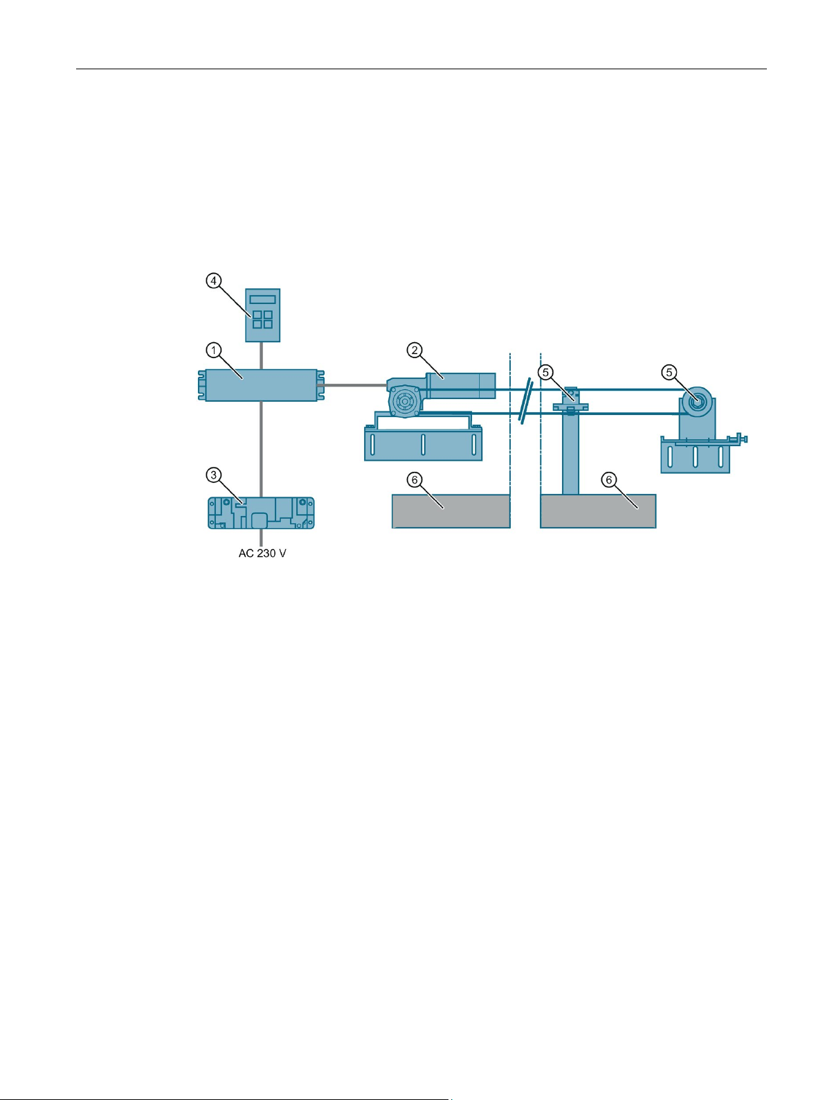
①
④
SIDOOR SOFTWARE KIT)
②
Geared motor
⑤
Accessories
③
Power supply
⑥
Sliding door
Elevators
SIDOOR AT40
SIDOOR ATD400V
2.2 System configuration and area of application
The graphic uses the example of a horizontal elevator door to illustrate the general structure
of an automatic door control unit with the SIDOOR system including the additional
components such as the power supply and drive.
Controller
Figure 2-1 System configuration
The following controllers are offered for use in elevators:
●
The comfort elevator door drive SIDOOR AT40 is an "intelligent" door drive with which
cabin and shaft doors can be operated with adjustable speeds and accelerations.
●
The rising gate and rolling shutter door drive SIDOOR ATD400V is an "intelligent" door
drive with which cabin and shaft doors can be operated with adjustable speeds and
accelerations.
Optional additional unit (for example SIDOOR SERVICE TOOL,
Door control units SIDOOR AT40 and ATD400V for elevators
System Manual, 06/2018, A5E42192709-AC
11

System overview
2.3
Products
Note
The SIDOOR AT12 product is described in a separate documentation. You can find the
Equipment Manual on the Internet
(
2.3.1
Controllers
Controllers for elevator door systems
Controller
Article No.
Description
Elevator door control units
2.3 Products
The included parts are described in the following chapters:
● Controllers
● Motors
● Power supply units
https://support.industry.siemens.com/cs/ww/en/view/58497029)
Controllers are electronic control units connected to the power supply via an external power
supply unit (SIDOOR NT40, SIDOOR TRANSFORMER). They can be parameterized via a
user interface.
The controllers are designed for different areas of application. The following table provides
an overview of the available controllers.
The following table provides you with an overview of the controllers for elevator doors.
SIDOOR AT40 RELAY 6FB1111-0AT10-3AT2
SIDOOR AT40 CAN 6FB1111-1AT10-3AT3
SIDOOR AT40 BASIC 6FB1111-0AT11-3AT0
SIDOOR
ATD400V RELAY
6FB1111-1AT10-3VE2
• Controller for horizontal elevator doors, up to 600 kg door weight
• including relay module
• Controller for horizontal elevator doors, up to 600 kg door weight
• Including CAN module (interface for superior elevator control)
• Controller for horizontal elevator doors, up to 600 kg door weight
• Basic device without CAN / RELAY module, without terminal mod-
ule
• Controller for rising gate and rolling shutter doors in the elevator
field of application, vertical, up to 600 kg (M4 and M5) door weight
• Including relay module
Door control units SIDOOR AT40 and ATD400V for elevators
12 System Manual, 06/2018, A5E42192709-AC
System overview
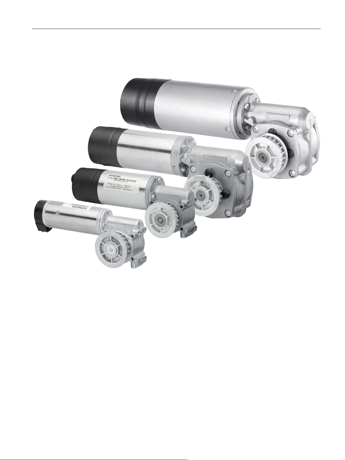
2.3.2
Geared motors
2.3 Products
Geared motors form the maintenance-free drive unit in the door drive. The geared motors
feature DC motors with non-self-locking gearing and are speed-controlled. The set force and
speed limits are not exceeded.
The force transfer takes place by means of a toothed belt which passes over a deflector
pulley and can be fitted with two clutch holders. This enables both single-sided and centrallyopening doors to be driven.
Door control units SIDOOR AT40 and ATD400V for elevators
System Manual, 06/2018, A5E42192709-AC
13

System overview
Versions
Note
SIDOOR
SIDOOR M5 motors. The SIDOOR ATD400V controller can only be operated with the
SIDOOR M4 and SIDOOR M5 motors.
Geared motor
Article No.
Description
See also
2.3 Products
AT40 controllers operate the SIDOOR M2, SIDOOR M3, SIDOOR M4 and
SIDOOR M2 L 6FB1103-0AT10-5MA0
SIDOOR M2 R 6FB1103-0AT11-5MA0
SIDOOR M3 L 6FB1103-0AT10-4MB0
SIDOOR M3 R 6FB1103-0AT11-4MB0
SIDOOR M4 L 6FB1103-0AT10-3MC0
SIDOOR M4 R 6FB1103-0AT11-3MC0
SIDOOR M5 L 6FB1103-0AT10-3MD0
SIDOOR M5 R 6FB1103-0AT11-3MD0
• Geared motor, pinion left, max. 120 kg moved mass
• Cable length 1.5 m
• Geared motor, pinion right, max. 120 kg moved mass
• Cable length 1.5 m
• Geared motor, pinion left, max. 180 kg moved mass
• Cable length 1.5 m
• Geared motor, pinion right, max. 180 kg moved mass
• Cable length 1.5 m
• Geared motor, pinion left, max. 400 kg moved mass
• Cable length 1.5 m
• Geared motor, pinion right, max. 400 kg moved mass
• Cable length 1.5 m
• Geared motor, pinion left, max. 600 kg moved mass
• Cable length 1.5 m
• Geared motor, pinion right, max. 600 kg moved mass
• Cable length 1.5 m
Accessories (Page 16)
Door control units SIDOOR AT40 and ATD400V for elevators
14 System Manual, 06/2018, A5E42192709-AC
System overview
2.3.3
Power supply
Device selection
Note
SIDOOR TRANSFORMER may only be used with the motors SIDOOR M2, SIDOOR M3
and SIDOOR M4.
Power supply
Article No.
Description
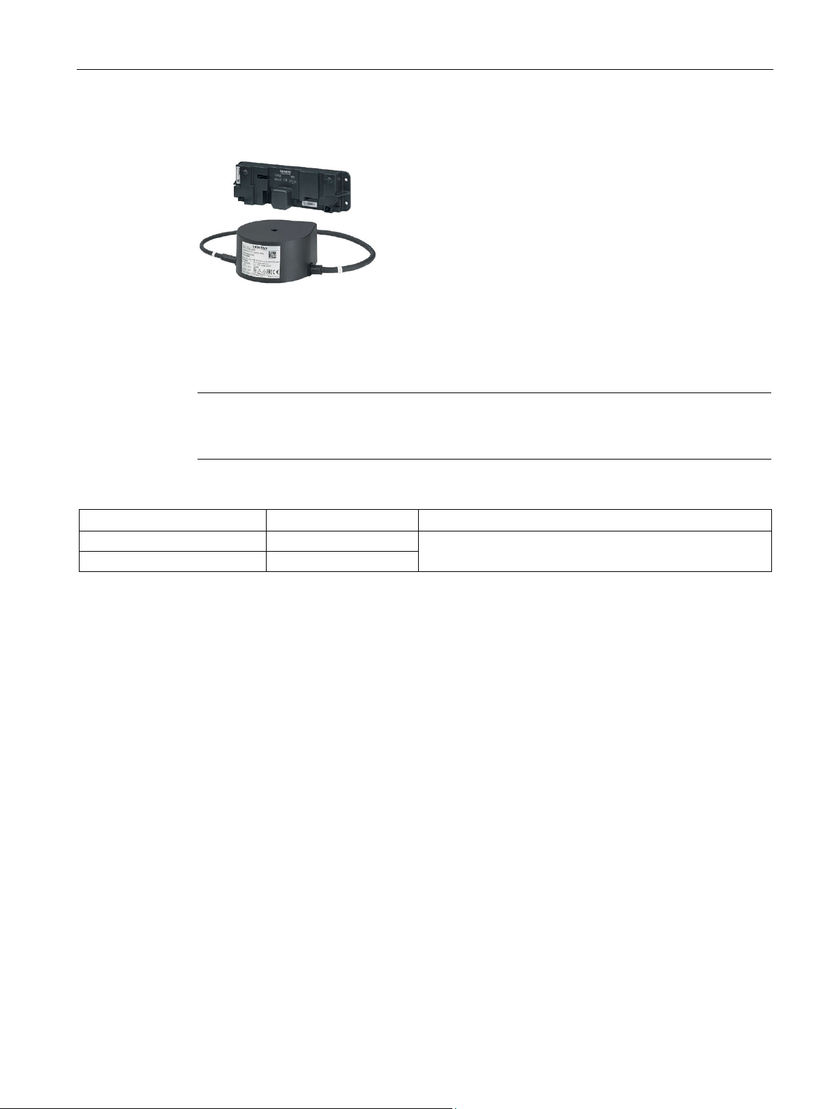
SIDOOR NT40
6FB1112-0AT20-3PS0
SIDOOR TRANSFORMER
6FB1112-0AT20-2TR0
2.3 Products
SIDOOR power supplies connect the controllers to the respective application-specific power
supply.
Power supply for controllers without an integrated power
supply unit.
Door control units SIDOOR AT40 and ATD400V for elevators
System Manual, 06/2018, A5E42192709-AC
15

System overview
2.3.4
Accessories
Accessories
Article No.
Description
ed
SIDOOR deflector pulley
6FB1104-0AT04-0AS0
Deflector pulley for deflecting the SIDOOR toothed belt
Note:
Note:
2.3 Products
SIDOOR rubber-metal
anti-vibration mount
SIDOOR mounting bracket
SIDOOR deflector unit 6FB1104-0AT03-0AS2
SIDOOR door clutch
holder
6FB1104-0AT01-0AD0
6FB1104-0AT02-0AD0
6FB1104-0AT01-0AS0 Mounting bracket for mounting the SIDOOR rubber-metal anti-
6FB1104-0AT02-0AS0
6FB1104-0AT01-0CP0
6FB1104-0AT02-0CP0
• Rubber-metal anti-vibration mount for quiet operation of the door
drive system
• Recommended for mounting SIDOOR M4 R / L and M5 R / L
geared motors
• Rubber-metal anti-vibration mount for quiet operation of the door
drive system
• Recommended for mounting SIDOOR M2 R / L and M3 R / L
geared motors
vibration mount on which, in turn, a SIDOOR geared motor is mount-
• Mounting bracket with tensioning device for deflector pulley
• For mounting the SIDOOR deflector unit and for tensioning the
SIDOOR toothed belt
• Deflector unit with deflector pulley
• For deflecting the SIDOOR toothed belt in the same height and
depth, aligned with motor drive pinion
• Door clutch holder for 12 mm-wide toothed belt (
belt width of 12 mm is to be used preferentially for SIDOOR M2
and SIDOOR M3.)
• For attaching both ends of the toothed belt, and for connecting
the respective door panel to the toothed belt
• Door clutch holder for 14 mm-wide toothed belt (
belt width of 14 mm is to be used preferentially for SIDOOR M4
and SIDOOR M5.)
• For attaching both ends of the toothed belt, and for connecting
the respective door panel to the toothed belt
Toothed
Toothed
Door control units SIDOOR AT40 and ATD400V for elevators
16 System Manual, 06/2018, A5E42192709-AC
System overview
Accessories
Article No.
Description
2.3.5
SIDOOR SERVICE TOOL
Selection of additional units
Additional unit
Article No.
Description
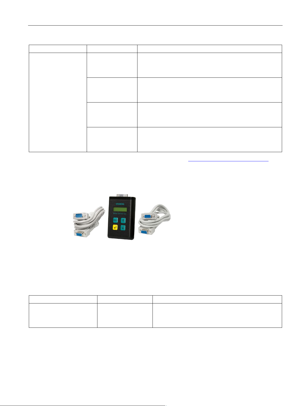
nals of the service data and the current firmware version.
2.3 Products
SIDOOR toothed belt 6FB1104-0AT01-0AB0
6FB1104-0AT02-0AB0
6FB1104-0AT03-0AB0
6FB1104-0AT04-0AB0
You will find more accessories in the Industry Mall (http://www.siemens.com/siplus/mall)
• Single-toothed STS
• Super Torque toothed belt
• Length 4 m, width 12 mm.
• Single-toothed STS
• Super Torque toothed belt
• Length 45 m, width 12 mm.
• Single-toothed STS
• Super Torque toothed belt
• Length 4 m, width 14 mm.
• Single-toothed STS
• Super Torque toothed belt
• Length 55 m, width 14 mm.
Additional units meet a range of customer requirements in order to ensure the universal
implementation and maintenance of the system.
The additional units are easy to connect to a deenergized controller via the interfaces
provided – and are available for use as soon as the power supply is connected.
SIDOOR SERVICE TOOL 6FB1105-0AT01-6ST0 The SIDOOR Service Tool can be used to enter door com-
mands, to change the drive parameters and to read the
taught parameters, the door states, the input and output sig-
Door control units SIDOOR AT40 and ATD400V for elevators
System Manual, 06/2018, A5E42192709-AC
17
System overview
2.3.6
SIDOOR SOFTWARE KIT
Selection
Software
Article No.
Description
2.3 Products
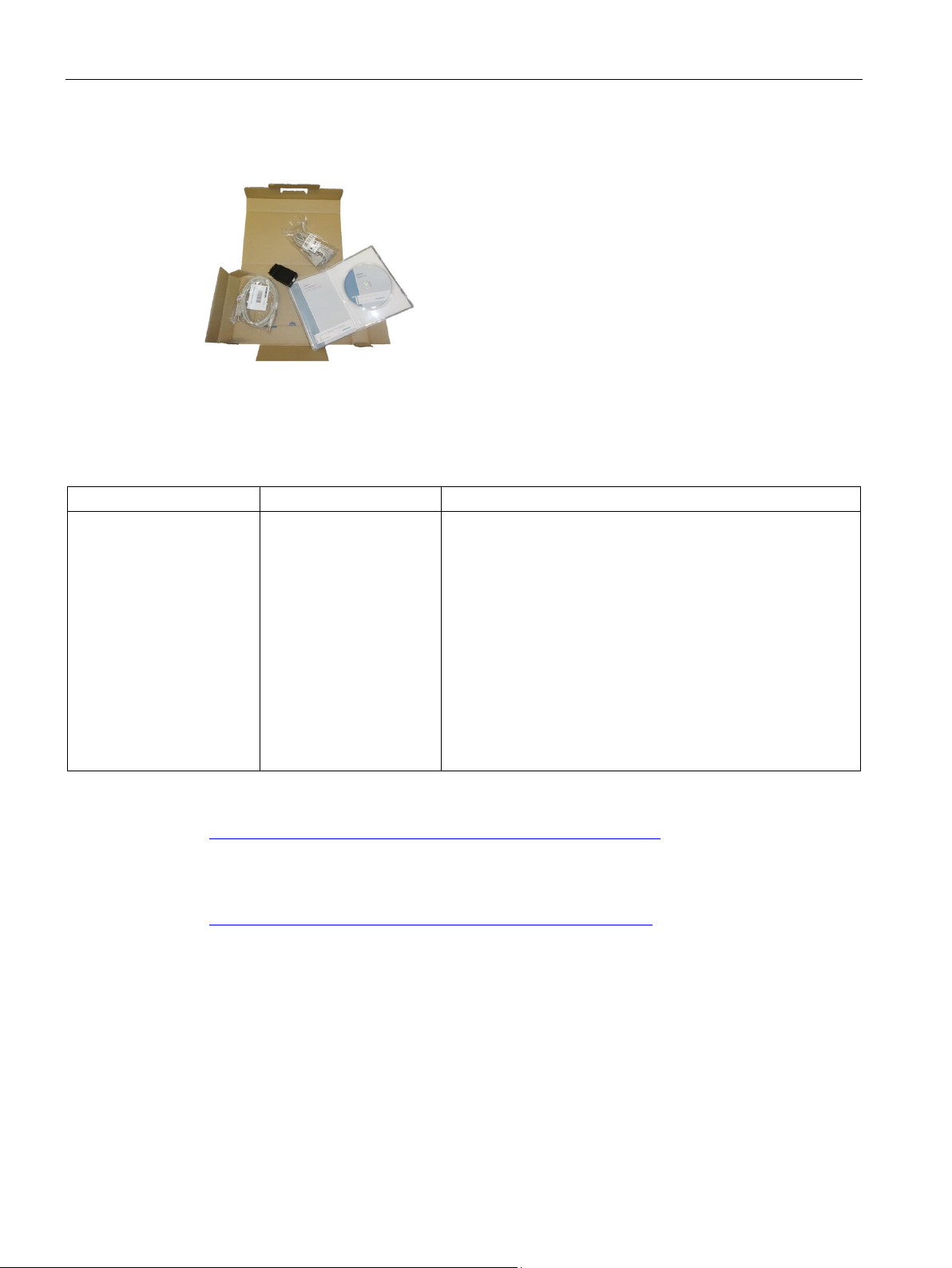
The optional SIDOOR Software Kit facilitates user-friendly operation and detailed diagnostics
via a PC.
SIDOOR SOFTWARE KIT 6FB1105-0AT01-6SW0 The package includes the following components:
• Installation CD (Software Kit)
– SIDOOR User Software
– Siemens HCS12 Firmware Loader
– SIDOOR USB to UART Bridge Driver
– License provisions
– SIDOOR SOFTWARE KIT Operating Instructions
• 1 x USB adapter
• 1 x USB connecting cable
• 1x D-SUB connecting cable (9-pin, plug/socket)
• 1x D-SUB connecting cable (9-pin, socket/socket)
The entire contents of the installation CD from the SIDOOR SOFTWARE KIT are also
available Installation package
(https://support.industry.siemens.com/cs/ww/en/view/109481599
) in the Industry Online
Support.
You can find additional information about the SIDOOR SOFTWARE KIT in the SIDOOR
SOFTWARE KIT Operating Instructions
(http://support.automation.siemens.com/WW/view/en/92711247
).
Door control units SIDOOR AT40 and ATD400V for elevators
18 System Manual, 06/2018, A5E42192709-AC

3
Overview
Basic functions:
System functions:
Extended functions:
Functions
Functions
SIDOOR
AT40
ATD400V
Basic functions
Learn run (Page 20)
✓
✓
DCPS (Door Closed Position Sensor) (Page 24)
✓1)
✓1)
CLOSE DOOR (command given via digital inputs) (Page 26)
✓
✓
OPEN DOOR (command given via digital inputs) (Page 26)
✓
✓
System functions
Restart after power failure (Page 27)
✓
✓
Overload protection (Page 28)
✓
✓
Vandalism protection/continuous door monitoring (Page 28)
✓
✓
Automatic energy limiting (Page 29)
✓
✓
External closing force (Page 34)
✓
✓
Extended functions
Obstruction detection (Page 34)
✓
✓
Maintenance data (Page 35)
✓
✓
Emergency power mode (Page 44)
✓2)
✓2)
Spring mechanism in closed position (Page 43)
✓
✓
Light barrier
Light barrier (Page 45)
✓1)
✓1)
1)
2)
Emergency power mode and light barriers with feedback contact cannot be implemented simultaneously.
This section describes all the functions of the SIDOOR control devices.
The functions are divided into:
●
●
system.
●
requirements.
Table 3- 1 Available SIDOOR functions
Functions that you always require to use a SIDOOR door control system.
Functions that enable you to better monitoring and diagnose the
Functions that you can use to implement application-specific
Oscillation protection (Page 28) ✓ ✓
Emergency release (Page 32) ✓ ✓
Light barrier and DCPS cannot be implemented at the same time.
Door control units SIDOOR AT40 and ATD400V for elevators
System Manual, 06/2018, A5E42192709-AC
19

SIDOOR functions
3.1
Basic functions
Introduction
3.1.1
Learn run
Description of function
WARNING
Note
If a DCP sensor is used, the position of the DCP sensor is determined during the learn run.
If the DCP sensor position i
Types of learn run (via learn run button)
When the line voltage is applied
During operation
3.1 Basic functions
You will also need the basic functions described below to use a SIDOOR door controller.
A learn run is used to determine and store the characteristics of a particular system.
During the learn run the door area must be secured in such a manner that unauthorized
persons cannot enter the operating area of the doors.
During the learn run, increased forces and energies can occur at the door.
s changed, a new learn run must be carried out.
Two types of learn run can be performed if the learn run button is pressed as follows:
●
If the learn run button is operated directly when the line voltage is applied, the connected
motor type is learned. All driving parameters as well as force and energy limiting
parameters are automatically reset to their factory defaults before the learn run is begun.
The learn run determines the door width, weight and CLOSED position. In addition, the
speed in nudging mode and the maximum closing speed are preset depending on the
permissible energy and the moved mass.
Application examples: initial commissioning or when commissioning a new motor type
●
If the learn run button is actuated during ongoing operation, a learn run is started to
determine the door's width, weight and CLOSED position. In addition, the speed in
nudging mode and the maximum closing speed are preset depending on the permissible
energy and the moved mass.
Application examples: Modifying the properties of the door system (door width or door
weight)
Door control units SIDOOR AT40 and ATD400V for elevators
20 System Manual, 06/2018, A5E42192709-AC

SIDOOR functions
Starting a learn run via the learn run button
Querying determined values
See also
3.1.2
Learn run button
Learn run button
Note
Two types of learn run can be perf
Learn run with standard parameters:
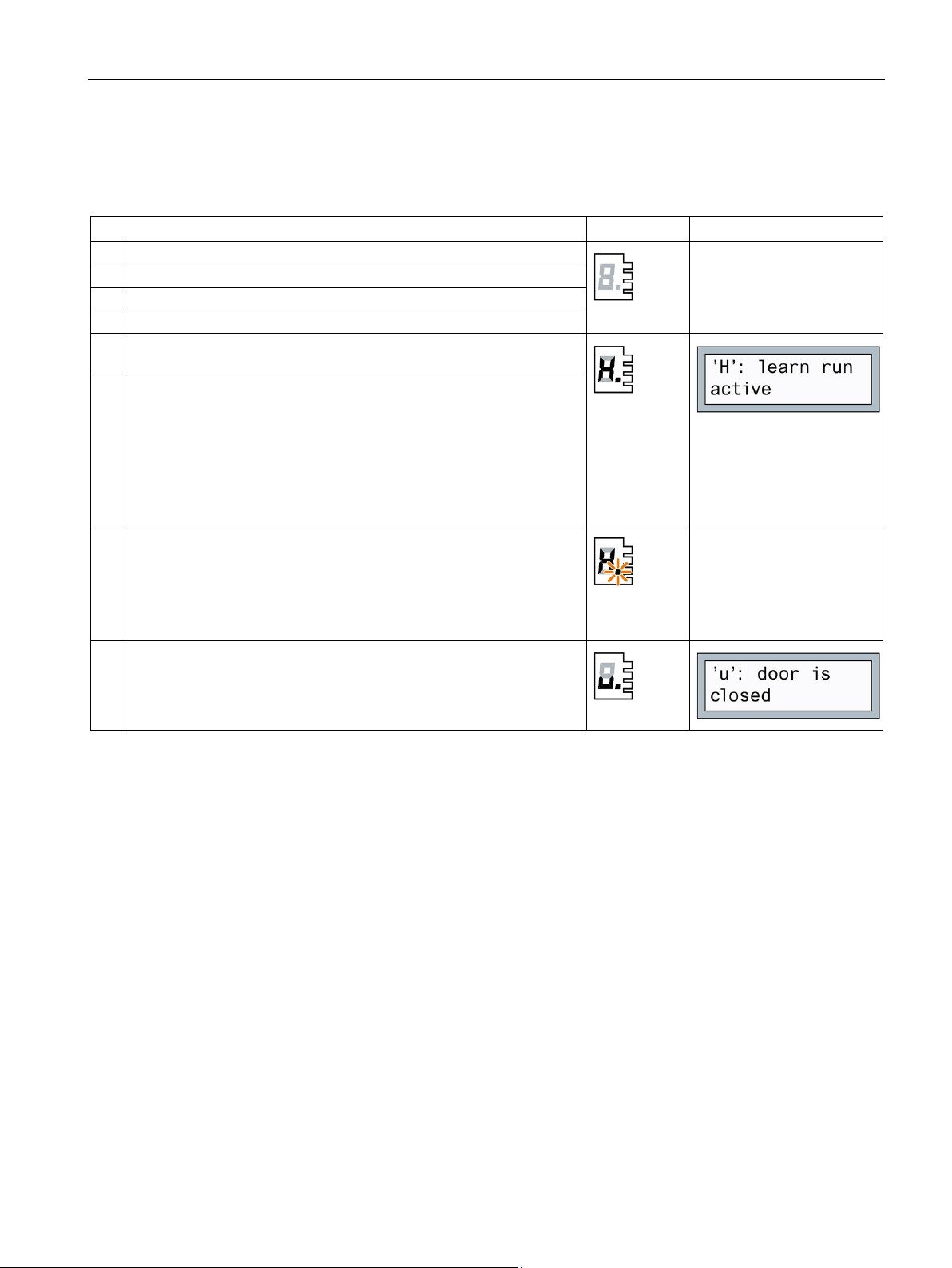
7-segment display
Description
"_"
No motor has yet been learned. Learn run required.
"5"
New motor type detected.
"P"
Learn run canceled.
Maximum door width:
Note
If a DCP sensor is used, the position of the DCP sensor is d
If the DCP sensor position is changed, a new learn run must be performed.
3.1 Basic functions
You can start a learn run by pressing the learn run button (S401). Proceed as described in
the section Learn run button (Page 21).
The determined values for the effective weight and the door width can be queried via the
terminal module as well as via the SIDOOR SOFTWARE KIT and SIDOOR SERVICE
TOOL.
Operating state display (Page 134)
You can start a learn run with the learn run button (S401).
ormed. See section Learn run (Page 20).
With the following display, a learn run is to be started via the service menu "
Start learn run with standard parameters
General setup >
":
The direction of travel, the door width and the moved mass are determined during the learn
run.
The maximum door width must be within the range of 30 cm to 5 m.
The maximum moved mass depends on the motor used.
Door control units SIDOOR AT40 and ATD400V for elevators
System Manual, 06/2018, A5E42192709-AC
etermined during the learn run.
21
SIDOOR functions
Parameter assignment
Note
If a slightly too la
the mains voltage is applied again, the active "initial mode" is not exited and the door always
runs at initial speed. In this case, the effective force during the learn run should
If an obstruction occurs during the learn run (e.g. sluggish door), the effective force during
the learn run can be increased.
After changing the effective forces during the learn run, a "normal" learn run should be
performed.
During a learn run with default parameters, the effective forces during the learn run are reset
to the default values from the factory setting.
WARNING
Ensure that the door is in the CLOSED position.
Ensure that 10 to 20 cm of the door's range of motion from the CLOSED position are
unobstructed during the learn run.
The motor temperature must be above 0 °C during the learn run, as otherwise the
weight of the door will be incorrectly determined, and the closing speed may be in an
impermissible range.
Any door command that may be pending is executed immediately upon completion of
the learn run.
Ensure that the door is secured by a barrier before starting a learn run and during
commissioning.
The door movements can be externally controlled while the controller is being
commissioned.
Increased forces, speeds and energies occur in the closing and opening directions
during the learn run.
3.1 Basic functions
The force limit for the opening and closing direction can be set via the service menu with
General setup > Special parameters > Limit force open learn run
"
Special parameters > Limit force close learn run
".
" and "
General setup >
The default value for the force limit in the opening direction during the learn run corresponds
to the high force limit in the opening direction.
The default value for the force limit in closing direction during the learn run is 150 N for AT40
and 230 N for ATD400V.
The higher effective force limit from the opening or closing direction is used to determine the
closed position.
rge door width is determined during the learn run, it can happen that after
be reduced.
•
•
•
•
•
•
•
Door control units SIDOOR AT40 and ATD400V for elevators
22 System Manual, 06/2018, A5E42192709-AC
SIDOOR functions
Learn run (when the supply voltage is applied)
Procedure
H401 display
H1 display
1.
Push the door into the CLOSED position.
3.
Press the learn run button (S401) and keep it pressed.
4.
Connect the power supply to X3 (DC).
released.
losed once
termine the weight of the door.
mass and permissible energies.
Note:
3.1 Basic functions
Table 3- 2 Starting a learn run when the line voltage is applied
2. Disconnect the power supply from X3 (DC).
5. The learn run starts automatically and the learn run button can be
6. During the learn run, the door is opened about 10 cm, and c
or twice at creep speed. The friction of the door system is then determined by opening and closing the door once through a range of 25 cm
at creep speed.
The door then opens and closes through its complete range of movement at reduced speed. After the door has opened by approximately
15 cm, it passes through an additional short acceleration ramp to de-
7. The door parameters and the determined door width are saved when
the door is in the CLOSED position.
This means that the door width and weight are re-adapted and saved.
In addition, the default values for the driving curve parameters are
loaded and the speed limits are preset on the basis of the determined
8. Learn run completed.
If the light barrier / DCPS is set to light barrier and no light barrier is connected or if the light barrier bypass is not inserted, the 7segment display shows "0".
Door control units SIDOOR AT40 and ATD400V for elevators
System Manual, 06/2018, A5E42192709-AC
23
SIDOOR functions
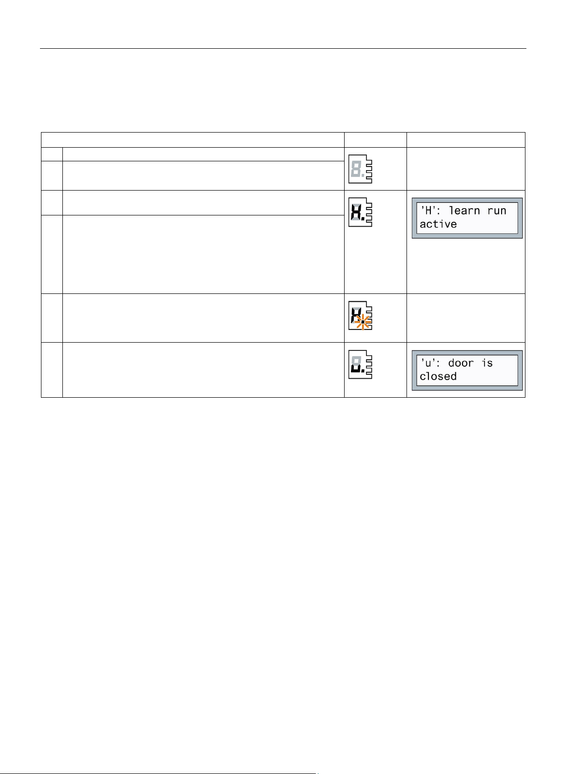
Learn run (during operation)
Procedure
H401 display
H1 display
1.
Push the door into the CLOSED position.
released.
tion ramp to determine the weight of the door.
speed limitation are re-adapted and saved.
3.1.3
DCPS (Door Closed Position Sensor)
Description of function
3.1 Basic functions
Table 3- 3 Starting a learn run during operation
2. Press the learn run button (S401) and keep it pressed.
3. The learn run starts automatically and the learn run button can be
4. During the learn run, the door is opened about 10 cm, and closed once
or twice at creep speed. The friction of the door system is then determined by opening and closing the door once through a range of 25 cm
at creep speed. The door then opens and closes through its complete
range of movement at reduced speed. After the door has opened by
approximately 15 cm, it passes through an additional short accelera-
5. The door parameters and the determined door width are saved when
the door is in the CLOSED position.
This means that the door width, door weight, energy limitation and
6. Learn run completed.
DCPS stands for Door Closed Position Sensor or DOOR CLOSED sensor. The Door Closed
Position Sensor is not a special sensor, but an open or closed contact as far as the controller
is concerned. If the contact is closed, the door is in the CLOSED position. The user is
responsible for the design of the contact.
The DCPS enables the door to travel in normal operation immediately after the line voltage is
switched on without an initialization run. This requires the door to be in the CLOSED position
when the power is switched on. This enables the controller to be completely switched off if
the elevator is not going to be used for a lengthy period, for example during the night.
If the contact remains closed although the door has left its CLOSED position, the controller
switches to initial operation after 10 cm, and continues the movement at initial speed. The
door does not resume moving at normal speed until after it has traveled to both end
positions.
Door control units SIDOOR AT40 and ATD400V for elevators
24 System Manual, 06/2018, A5E42192709-AC

SIDOOR functions
Connection and parameter assignment
Note
The light barrier and DCPS functions cannot be implemented simultaneously.
Note
During the learn run, the position of the DCP sensor is determined and saved. If the positio
of the DCP sensor was changed, you have to execute another learn run.
Signals
Signal
Description
1 (voltage applied)
Door is in the CLOSED position
0 (voltage not applied)
Door is not in the CLOSED position
3.1 Basic functions
The DCPS signal can be connected via the input terminal X6 Pin 5/6. See also Section
Digital input signals (Page 51). The connected signal must be activated via the SIDOOR
SERVICE TOOL, Terminal Module (not available for AT40 BASIC) or SIDOOR SOFTWARE
MAIN MENU > General setup > Special parameters > Input 1
KIT (
).
When the DCPS has been configured (service menu "
Input 1 = DCPS
"), the "DOOR CLOSE" status is signaled under the following conditions:
General setup > Special parameters >
● In initial mode, when the DCPS signal is active, no opening command is applied and no
DCPS error is pending.
● In normal mode, when the DCPS signal is active, no opening command is applied and the
door is in the slow start / end distance mode.
● During closing travel the CLOSE relay (X11) picks up when the DCPS signal is active and
the door is in the slow start / end distance mode.
● When the door is pushed open manually, the CLOSE relay drops out (as soon as the
DCPS signal becomes inactive).
● If the DCPS signal is active for a longer stretch than 10 cm, or at a distance of more than
10 cm to the CLOSE position, this is recognized as a DCPS error and the system
changes to the initial mode.
● A DCPS error is reset when both end positions of the door have been recognized and the
door control unit is in the normal mode.
● The control system changes from the initial mode into the normal mode,"Closed" state,
when the DCPS signal is active in the initial module during an obstruction in the closing
direction or during switching on.
Door control units SIDOOR AT40 and ATD400V for elevators
System Manual, 06/2018, A5E42192709-AC
n
25

SIDOOR functions
3.1.4
DOOR CLOSE (command given via digital inputs)
Description of function
Note
If the commands DOOR CLOSE and DOOR OPEN are present s
always moves in the OPEN direction. The DOOR OPEN command takes the highest priority
against all other control commands.
Connection
Signals
Signal
Description
1 (voltage applied)
The DOOR CLOSE command is present
0 (voltage not applied)
The DOOR CLOSE command is not present
3.1.5
DOOR OPEN (command given via digital inputs)
Description of function
Exceptions:
Note
If the command
always moves in the OPEN direction.
3.1 Basic functions
The DOOR CLOSE command closes the door according to the set driving curve as long as
the command is present. The door reaches the CLOSED position at slow end speed close.
In the area of the slow start and end distances, the force is limited to the configured limit
force. Then the door is kept closed for 2 seconds with the "Peak torque close" parameter
and then with the "Idle torque close" parameter.
imultaneously, the door
The "DOOR CLOSE" function is connected to the input terminal X6 Pin 2. See also Section
Digital input signals (Page 51).
The DOOR OPEN command opens the door according to the set driving curve as long as
the command is present. The door reaches the OPEN position at creep speed. Then, if the
DOOR OPEN command is present, the door is held open by the torque that can be adjusted
by the parameter "Continuous torque OPEN".
The DOOR OPEN command has priority over all other control commands.
s DOOR CLOSE and DOOR OPEN are present simultaneously, the door
Door control units SIDOOR AT40 and ATD400V for elevators
26 System Manual, 06/2018, A5E42192709-AC

SIDOOR functions
Connection
Signals
Signal
Description
1 (voltage applied)
The DOOR OPEN command is present
3.2
System functions
Introduction
3.2.1
Restart after power failure
Description of function
3.2 System functions
The "DOOR OPEN" function is connected to the input terminal X6 Pin 1. See also Section
Digital input signals (Page 51).
0 (voltage not applied) The DOOR OPEN command is not present
The system functions described below enable better monitoring and diagnostics of the
system.
After a power failure, the controller has to redetermine the end positions of the door travel.
To do this, the door travels at reduced speed (initial speed) until the controller has detected
the OPEN and CLOSED end positions. The door then resumes traveling at normal speed.
Changes in the driving curve parameters are applied in the initial mode at a standstill.
The CLOSE relay (X11) picks up when a "DOOR CLOSE" command is active and the door
is blocked for at least 1 second in the CLOSE direction. The CLOSE relay (X11) drops off
when the door has moved from the blocking position by 1 cm in the OPEN direction, or a
"DOOR OPEN" command is active.
The OPEN relay (X13) picks up when a "DOOR OPEN" command is active and the door is
blocked for at least 1 second in the OPEN direction in initial mode. The OPEN relay (X13)
drops off when the door has moved from the blocking position by 2 cm in the CLOSE
direction, or a "DOOR CLOSE" command is active.
The initial mode can be skipped by connecting an end position sensor (DCPS) in the closed
position.
The door travels open immediately with the normal speed when the DCPS (see Chapter
DCPS (Door Closed Position Sensor) (Page 24)) is set up. In this case, the door must be in
the CLOSED position for the restart.
If a defect in the end position sensor is recognized (sensor is active across a distance of
more than 10 cm), the system changes back to the initial mode (see section DCPS (Door
Closed Position Sensor (Page 24))).
Door control units SIDOOR AT40 and ATD400V for elevators
System Manual, 06/2018, A5E42192709-AC
27

SIDOOR functions
3.2.2
Overload protection
Description of function
3.2.3
Vandalism protection/continuous door monitoring
Description of function
3.2.4
Oscillation protection
End position "open"
3.2 System functions
If the drive motor placed under a high load with frequent DOOR OPEN and DOOR CLOSE
commands in quick succession, the hold-open time is automatically lengthened. The next
closing movement is delayed even if a DOOR CLOSE command is present, the 7-segment
display (H401)/digital display (H1) shows "4". This function prevents thermal overloading of
the motor.
Reversing the direction of rotation or restarting the controller several times puts a
disproportionate strain on the drive motor.
The controller switches to motor protection mode for 30 seconds and does not accept any
door commands. This state is signaled by a "4" on the 7-segment display (H401)/the digital
display (H1).
This function prevents thermal overloading of the motor.
The vandalism protection/continuous door monitoring function offers protection against
undesired external system motion. If the motor is deenergized, the motor speed is monitored
by the controller.
If no door command is applied and the door speed exceeds 200 mm/s, the controller actively
brakes the drive down to 50 mm/s and then deenergnizes the motor again.
The oscillation protection prevents permanent oscillation of the door at the end stop.
If the system is pressed out of the end position with the drive order "open" present, the
system detects that the "open" position has been left, and attempts to return to the end stop
with the set static opening force.
After reaching the end stop, the drive is energized with the set continuous torque.
The behavior described may be repeated five times (oscillation). After the fifth repetition, the
drive is energized for 30 s with the set continuous torque without any response to further
oscillations. After a protective period of 30 s, the system responds once again to
corresponding oscillations.
Door control units SIDOOR AT40 and ATD400V for elevators
28 System Manual, 06/2018, A5E42192709-AC

SIDOOR functions
End position "closed"
3.2.5
Automatic energy limitation
Description of function
WARNING
Risk of injury due to moving mechanical parts
Note
The actual kinetic energy occurring in the closing direction has to be checked during
commissioning, and the parameters "
may have to be adapted.
3.2 System functions
If the system is pressed out of the end position with the drive order "close" present, the
system detects that the "closed" position has been left, and attempts to return to the end
stop with the set static cutter force.
After reaching the end stop, the drive is energized with the set cutter press-on torque. After
2 s, the cutter press-on torque is limited to the set continuous torque.
The behavior described may be repeated five times (oscillation). After the fifth repetition, the
drive is energized for 30 s with the set continuous torque without any response to further
oscillations. After a protective period of 30 s, the system responds once again to
corresponding oscillations.
SIDOOR control devices have a system that automatically limits the kinetic energy in the
closing direction.
Irrespective of the maximum closing speed determined automatically during the learn run,
after a learn run the kinetic energy of the door in the closing direction must be checked by
the commissioning engineer.
• According to EN 81, the kinetic energy of the door in the closing direction must not
exceed the value of 10 joules while the reversing unit is enabled.
• Without an enabled reversing unit, the kinetic energy of the door in the closing direction
must not exceed the value of 4 joules according to EN 81 and each closing operation
must be signaled acoustically. The acoustic signal required in the standard is not part of
the SIDOOR system and must be provided and ensured externally by the operator.
The set maximum closing speed and the nudging speed must be reduced accordingly.
Check the final application-specific limit values and adjust them accordingly.
After a learn run, the parameter "
Nudging speed close
"
learn run.
Maximum speed close
" is set to 10 J and the parameter
" is set to 4 J based on the moved weight as determined during the
Maximum speed close
" and "
Nudging speed close
"
Door control units SIDOOR AT40 and ATD400V for elevators
System Manual, 06/2018, A5E42192709-AC
29
 Loading...