

SIDOOR AT40,SIDOOR ATD400V,SIDOOR ATD400K,SIDOOR ATD400S, ATE250S,SIDOOR ATD4xxW Series,SIDOOR ATD400T
Table of contents
 Loading...
Siemens SIDOOR AT40,SIDOOR ATD400V,SIDOOR ATD400K,SIDOOR ATD400S, ATE250S,SIDOOR ATD4xxW Series,SIDOOR ATD400T System Manual

Automatic Door Controls
SIDOOR
AT40, ATD400V, ATD400K, ATD4xxW, ATD400S, ATE250S, ATD400T
System Manual
siemens.com
06/2016Edition

AT40, ATD400V, ATD400K, ATD4xxW,
ATD400S, ATE250S, ATD400T
___________________
___________________
___________________
___________________
___________________
___________________
___________________
___________________
___________________
___________________
___________________
Automatic Door Controls
SIDOOR
AT40, ATD400V, ATD400K,
ATD4xxW, ATD400S, ATE250S,
ATD400T
System Manual
06/2016
A2B00096162
Introduction
1
General safety instructions
2
Product family
3
Areas of application
4
Product combinations
5
Controllers
6
Geared motors
7
Power supply
8
Connecting and
commissioning
9
Additional units
10
Appendix
A
-AN

Siemens AG
Division Digital Factory
Postfach 48 48
90026 NÜRNBERG
GERMANY
A2B00096162-AN
Ⓟ
Copyright © Siemens AG 2012 - 2016.
All rights reserved
Legal information
Warning notice system
DANGER
indicates that death or severe personal injury will result if proper precautions are not taken.
WARNING
indicates that death or severe personal injury may result if proper precautions are not taken.
CAUTION
indicates that minor personal injury can result if proper precautions are not taken.
NOTICE
indicates that property damage can result if proper precautions are not taken.
Qualified Personnel
personnel qualified
Proper use of Siemens products
WARNING
Siemens products may only be used for the applications described in the catalog and in the relevant technical
ambient conditions must be complied with. The information in the relevant documentation must be observed.
Trademarks
Disclaimer of Liability
This manual contains notices you have to observe in order to ensure your personal safety, as well as to prevent
damage to property. The notices referring to your personal safety are highlighted in the manual by a safety alert
symbol, notices referring only to property damage have no safety alert symbol. These notices shown below are
graded according to the degree of danger.
If more than one degree of danger is present, the warning notice representing the highest degree of danger will
be used. A notice warning of injury to persons with a safety alert symbol may also include a warning relating to
property damage.
The product/system described in this documentation may be operated only by
task in accordance with the relevant documentation, in particular its warning notices and safety instructions.
Qualified personnel are those who, based on their training and experience, are capable of identifying risks and
avoiding potential hazards when working with these products/systems.
Note the following:
documentation. If products and components from other manufacturers are used, these must be recommended
or approved by Siemens. Proper transport, storage, installation, assembly, commissioning, operation and
maintenance are required to ensure that the products operate safely and without any problems. The permissible
All names identified by ® are registered trademarks of Siemens AG. The remaining trademarks in this publication
may be trademarks whose use by third parties for their own purposes could violate the rights of the owner.
We have reviewed the contents of this publication to ensure consistency with the hardware and software
described. Since variance cannot be precluded entirely, we cannot guarantee full consistency. However, the
information in this publication is reviewed regularly and any necessary corrections are included in subsequent
editions.
for the specific
06/2016 Subject to change

Table of contents
1 Introduction ........................................................................................................................................... 11
2 General safety instructions .................................................................................................................... 14
3 Product family ....................................................................................................................................... 17
4 Areas of application .............................................................................................................................. 29
5 Product combinations............................................................................................................................ 32
6 Controllers ............................................................................................................................................ 33
3.1 Products ................................................................................................................................. 19
3.1.1 Controllers .............................................................................................................................. 19
3.1.2 Geared motors ....................................................................................................................... 21
3.1.3 Accessories ............................................................................................................................ 23
3.1.4 Power supply .......................................................................................................................... 26
3.1.5 Optional additional units ......................................................................................................... 27
3.1.6 Software ................................................................................................................................. 28
4.1 Elevators ................................................................................................................................ 29
4.2 Industrial applications ............................................................................................................ 30
4.3 Railways ................................................................................................................................. 31
6.1 Description ............................................................................................................................. 33
6.2 Drive functions ....................................................................................................................... 35
6.2.1 Overview ................................................................................................................................ 35
6.2.2 Light barrier ............................................................................................................................ 39
6.2.3 Motion detector ...................................................................................................................... 41
6.2.4 DCPS (Door Closed Position Sensor) ................................................................................... 41
6.2.5 DCOPS (door closed/opened position sensor) ...................................................................... 42
6.2.6 Type 2 ESPE .......................................................................................................................... 44
6.2.7 Pressure-sensitive edge (SR) ................................................................................................ 46
6.2.8 Gate interlocking .................................................................................................................... 47
6.2.9 Door locked ............................................................................................................................ 48
6.2.10 Nudge ..................................................................................................................................... 49
6.2.11 Stopping ................................................................................................................................. 49
6.2.12 Force and energy profiles (NDG mode) ................................................................................. 50
6.2.13 Slow driving curve profile ....................................................................................................... 51
6.2.14 Automatically delayed motion ................................................................................................ 52
6.2.15 Cord-operated switch ............................................................................................................. 53
6.2.16 DOOR CLOSE (command given via digital inputs) ............................................................... 54
6.2.17 DOOR OPEN (command given via digital inputs) ................................................................. 55
6.2.18 Partial opening ....................................................................................................................... 56
6.2.19 Restart after power failure ...................................................................................................... 57
6.2.20 Overload protection ................................................................................................................ 57
6.2.21 Vandalism protection/continuous door monitoring ................................................................. 58
AT40, ATD400V, ATD400K, ATD4xxW, ATD400S, ATE250S, ATD400T
4 System Manual, 06/2016, A2B00096162-AN

Table of contents
6.2.22 Obstruction detection .............................................................................................................. 59
6.2.22.1 Obstruction detection CLOSE ................................................................................................. 59
6.2.22.2 Obstruction detection OPEN ................................................................................................... 60
6.2.22.3 SIDOOR ATD4xxW obstruction detection .............................................................................. 61
6.2.23 ImpulseDrive ........................................................................................................................... 65
6.2.24 Automatic ImpulseDrive .......................................................................................................... 66
6.2.25 ImpulseStop ............................................................................................................................ 67
6.2.26 Automatic ImpulseStop ........................................................................................................... 68
6.2.27 AssistedDrive .......................................................................................................................... 69
6.2.28 Automatic AssistedDrive ......................................................................................................... 70
6.2.29 Initial run/reference run (Power ON) ....................................................................................... 71
6.2.30 Positioning mode .................................................................................................................... 72
6.2.31 Belt break monitoring .............................................................................................................. 73
6.2.32 Emergency power mode ......................................................................................................... 74
6.2.33 Friction compensation ............................................................................................................. 75
6.2.34 Oscillation protection............................................................................................................... 76
6.2.35 Automatic energy limitation ..................................................................................................... 77
6.2.36 External closing force.............................................................................................................. 81
6.2.37 Push to open ........................................................................................................................... 82
6.2.38 Pull to close ............................................................................................................................. 82
6.2.39 Emergency release ................................................................................................................. 82
6.2.40 Learn run ................................................................................................................................. 83
6.2.41 Force limit for learn run ........................................................................................................... 85
6.2.42 Output transmission ................................................................................................................ 86
6.2.43 Free function blocks (FBLOCK) .............................................................................................. 87
6.2.43.1 Overview ................................................................................................................................. 87
6.2.43.2 Configuring the logic ............................................................................................................... 88
6.2.43.3 Digital and logical input signals ............................................................................................... 90
6.2.43.4 Special function blocks ........................................................................................................... 91
6.2.43.5 Discrepancy analysis block ..................................................................................................... 91
6.2.43.6 Basic blocks ............................................................................................................................ 91
6.2.43.7 Frequency analysis blocks ...................................................................................................... 92
6.2.43.8 On delay block ........................................................................................................................ 92
6.2.43.9 Counter block .......................................................................................................................... 93
6.2.44 Drive orders ............................................................................................................................ 94
6.3 S
afety concept ATD4xxW ....................................................................................................... 98
6.3.1 Safe force output ..................................................................................................................... 98
6.3.2 Safe speed observance (energy limiting) ............................................................................... 98
6.3.3 Safe input signals according to PLd ....................................................................................... 98
6.3.3.1 Internal signal routing.............................................................................................................. 99
6.3.3.2 Redundant antivalent signal logic with discrepancy analysis ................................................. 99
6.3.3.3 Frequency-based input signals ............................................................................................. 101
6.3.3.4 Two-hand operation concept (according to Cat. IIIA) ........................................................... 101
6.3.3.5 Emergency stop concept in accordance with stop category 1 ............................................. 103
6.3.3.6 Concept of fail-safe digital control (door OPEN/CLOSE) with emergency stop via 4
digital inputs .......................................................................................................................... 104
6.3.3.7 Concept of fail-safe digital control (door OPEN/CLOSE) with emergency stop via 3
digital inputs .......................................................................................................................... 107
AT40, ATD400V, ATD400K, ATD4xxW, ATD400S, ATE250S, ATD400T
System Manual, 06/2016, A2B00096162-AN
5

Table of contents
6.4 Operation and parameter assignment ................................................................................. 109
6.4.1 Service buttons / Minimal editor ........................................................................................... 110
6.4.1.1 Service buttons .................................................................................................................... 110
6.4.1.2 Minimal editor ....................................................................................................................... 113
6.4.2 Terminal module .................................................................................................................. 116
6.4.3 Operating options via additional units .................................................................................. 118
6.4.4 Parameter names................................................................................................................. 118
6.4.5 Navigation structure ............................................................................................................. 120
6.5 Installation ............................................................................................................................ 126
6.6 Connecting terminals and interfaces ................................................................................... 129
6.6.1 Wiring instructions ................................................................................................................ 129
6.6.2 Digital input signals .............................................................................................................. 131
6.6.3 Voltage output*..................................................................................................................... 134
6.6.4 Relay module ....................................................................................................................... 135
6.6.5 CAN module ......................................................................................................................... 140
6.6.6 USS/PROFIBUS/PROFINET module .................................................................................. 143
6.6.6.1 USS module ......................................................................................................................... 143
6.6.6.2 PROFIBUS module .............................................................................................................. 145
6.6.6.3 PROFINET module .............................................................................................................. 148
6.6.6.4 Wiring and connecting a PROFIBUS/USS connector.......................................................... 154
6.6.6.5 Wiring and connecting a PROFINET connector .................................................................. 156
6.6.6.6 Wiring and connecting relay outputs .................................................................................... 157
6.6.7 Sensors and external sensor interface module (ATD4xxW) ................................................ 159
6.6.7.1 Overview .............................................................................................................................. 159
6.6.7.2 Type 2 ESPE ........................................................................................................................ 160
6.6.7.3 Pressure-sensitive edge (SR) .............................................................................................. 161
6.6.7.4 Sensor function test ............................................................................................................. 162
6.6.7.5 Reaction times ..................................................................................................................... 163
6.6.7.6 Stopping distances ............................................................................................................... 163
6.6.8 Motor plug ............................................................................................................................ 164
6.7 Parameters ........................................................................................................................... 165
6.7.1 Driving curve ........................................................................................................................ 165
6.7.2 Forces .................................................................................................................................. 166
6.7.3 Parameter assignment (ATD4xxW) ..................................................................................... 170
6.7.3.1 Driving parameters ............................................................................................................... 171
6.7.3.2 Other parameters
.7.3.3 Fieldbus parameters ............................................................................................................ 174
6
................................................................................................................. 172
6.7.3.4 Calibration and function parameters .................................................................................... 175
6.7.3.5 Obstruction and reversing parameters ................................................................................ 177
6.7.3.6 FBLOCK parameters ........................................................................................................... 180
6.8 Diagnostics ........................................................................................................................... 183
6.8.1 Operating state display ........................................................................................................ 183
6.8.2 Fault management (ATD4xxW) ........................................................................................... 185
6.9 Communication to PROFIBUS ............................................................................................. 186
6.9.1 Communication .................................................................................................................... 186
6.9.1.1 Parameter assignment ......................................................................................................... 186
6.9.1.2 Configuration ........................................................................................................................ 189
6.9.1.3 Diagnostics ........................................................................................................................... 190
AT40, ATD400V, ATD400K, ATD4xxW, ATD400S, ATE250S, ATD400T
6 System Manual, 06/2016, A2B00096162-AN

Table of contents
6.10 Communication to PROFINET .............................................................................................. 191
6.10.1 Parameterization/startup record ........................................................................................... 191
6.10.2 Configuration ......................................................................................................................... 193
6.10.3 Diagnostics ........................................................................................................................... 193
6.10.4 Device roles and provider-consumer model ......................................................................... 194
6.11 Structure of user data/process data ...................................................................................... 195
6.11.1 Parameter interface .............................................................................................................. 196
6.11.1.1 Parameter ID (PKE) .............................................................................................................. 197
6.11.1.2 Parameter index (IND) .......................................................................................................... 200
6.11.1.3 Parameter value (PWE) ........................................................................................................ 202
6.11.1.4 Parameter ID ......................................................................................................................... 203
6.11.1.5 Parameter description (PBE) ................................................................................................ 203
6.11.2 Process data ......................................................................................................................... 204
6.11.2.1 STW1 - control word (CtrlW) ................................................................................................. 205
6.11.2.2 TSW0 - technology control word 0 ........................................................................................ 206
6.11.2.3 TSW1 - technology control word 1 ........................................................................................ 206
6.11.2.4 TSW2 - technology control word 2 ........................................................................................ 207
6.11.2.5 ZSW1 - status word (StatW) ................................................................................................. 208
6.11.2.6 TZW0 - Technology status word 0 ........................................................................................ 209
6.11.2.7 TZW1 - Technology status word 1 ........................................................................................ 210
6.11.2.8 TZW2 - Technology status word 2 ........................................................................................ 212
6.11.2.9 TZW3 - Technology status word 3 ........................................................................................ 213
6.11.2.10 TZW4 - Technology status word 4 ........................................................................................ 214
6.11.2.11 TZW5 - Technology status word 5 ........................................................................................ 214
6.12 Local/master operation ......................................................................................................... 215
6.13 Master monitoring ................................................................................................................. 215
6.14 Sequential control ................................................................................................................. 216
6.15 Integration of SIMATIC S7 .................................................................................................... 218
6.15.1 Function block ....................................................................................................................... 219
6.15.1.1 "SIDOOR_CDat" data type ................................................................................................... 220
6.15.1.2 "SIDOOR_SDat" data type.................................................................................................... 221
6.15.2 Configuring PROFIBUS hardware (GSD file) ....................................................................... 222
6.15.3 Configuring PROFINET hardware (GSD file) ....................................................................... 222
6.
16 Technical specifications ........................................................................................................ 223
AT40, ATD400V, ATD400K, ATD4xxW, ATD400S, ATE250S, ATD400T
System Manual, 06/2016, A2B00096162-AN
7

Table of contents
7 Geared motors ..................................................................................................................................... 232
8 Power supply ....................................................................................................................................... 260
9 Connecting and commissioning ............................................................................................................ 280
7.1 Description ........................................................................................................................... 232
7.2 Installation ............................................................................................................................ 233
7.3 Connecting terminals ........................................................................................................... 238
7.3.1 Conductor assignment of the motor plug ............................................................................. 238
7.4 Technical specifications ....................................................................................................... 239
7.4.1 Dimension drawing of SIDOOR M2 with rubber-metal anti-vibration mount and
mounting bracket.................................................................................................................. 248
7.4.2 Dimension drawing of SIDOOR M3 / MDG180 DIN EN 45545-2 with rubber-metal anti-
vibration mount and mounting bracket ................................................................................. 249
7.4.3 Dimension drawing of SIDOOR MDG180 with rubber-metal anti-vibration mount and
mounting bracket.................................................................................................................. 250
7.4.4 Dimension drawing SIDOOR MEG250 ................................................................................ 251
7.4.5 Dimension drawing of SIDOOR M4 with rubber-metal anti-vibration mount and
mounting bracket.................................................................................................................. 253
7.4.6 Dimension drawing of SIDOOR MDG400 with rubber-metal anti-vibration mount and
mounting bracket.................................................................................................................. 254
7.4.7 Dimension drawing of SIDOOR M5 ..................................................................................... 255
7.4.8 Dimension drawing MDG400NMS ....................................................................................... 256
7.4.9 Dimension drawing of MDG motor cable ............................................................................. 257
7.4.10 Dimension drawing of deflector pulley with tensioning device and mounting bracket ......... 258
7.4.11 Dimension drawing of door clutch holder ............................................................................. 259
8.1 SIDOOR NT40 ..................................................................................................................... 260
8.1.1 Description ........................................................................................................................... 260
8.1.2 Installation ............................................................................................................................ 262
8.1.3 Connecting terminals ........................................................................................................... 263
8.1.4 Technical specifications ....................................................................................................... 265
8.2 SIDOOR Transformer .......................................................................................................... 268
8.2.1 Description ........................................................................................................................... 268
8.2.2 Installation ............................................................................................................................ 269
8.2.3 Connecting terminals ........................................................................................................... 270
8.2.4 Technical specifications ....................................................................................................... 271
8.3 Uninterruptible power supply (UPS) .................................................................................... 273
8.4 Direct voltage supply provided by customer ........................................................................ 276
8.4.1 Requirements for SIDOOR ATD400T power supply ........................................................... 276
8.4.2 Requirements for SIDOOR ATD4xxW power supply ........................................................... 277
8.4.3 Installation ............................................................................................................................ 279
AT40, ATD400V, ATD400K, ATD4xxW, ATD400S, ATE250S, ATD400T
8 System Manual, 06/2016, A2B00096162-AN

Table of contents
10 Additional units ................................................................................................................................... 289
A Appendix............................................................................................................................................. 296
10.1 SIDOOR EMC FILTER ......................................................................................................... 289
10.1.1 Description ............................................................................................................................ 289
10.1.2 Installation ............................................................................................................................. 289
10.1.3 Connecting terminals ............................................................................................................ 290
10.1.4 Technical specifications ........................................................................................................ 291
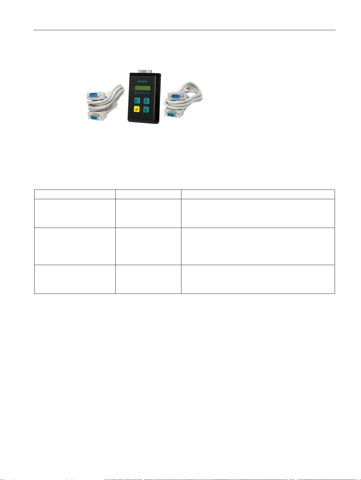
10.2 SIDOOR Service Tool ........................................................................................................... 292
10.2.1 Description ............................................................................................................................ 292
10.2.2 Connection ............................................................................................................................ 292
10.2.3 Operation .............................................................................................................................. 293
10.2.4 Technical specifications ........................................................................................................ 294
A.1 Profiles and adjustment ranges ............................................................................................ 296
A.1.1 Profile name .......................................................................................................................... 296
A.1.2 SIDOOR M2 L / R ................................................................................................................. 297
A.1.2.1 SIDOOR AT40/ATD400S ..................................................................................................... 297
A.1.2.2 SIDOOR ATD400W .............................................................................................................. 298
A.1.2.3 SIDOOR M2 adjustment ranges ........................................................................................... 299
A.1.3 SIDOOR M3 L / R ................................................................................................................. 300
A.1.3.1 SIDOOR AT40/ATD400S ..................................................................................................... 300
A.1.3.2 SIDOOR ATD400K ............................................................................................................... 301
A.1.3.3 SIDOOR ATD400W .............................................................................................................. 302
A.1.3.4 SIDOOR ATD4xxW ............................................................................................................... 303
A.1.3.5 SIDOOR ATD400T ............................................................................................................... 304
A.1.3.6 SIDOOR M3 adjustment ranges ........................................................................................... 305
A.1.4 SIDOOR MDG180 L / R ........................................................................................................ 307
A.1.4.1 SIDOOR ATD4xxW ............................................................................................................... 307
A.1.4.2 Adjustment ranges SIDOOR MDG180 ................................................................................. 307
A.1.5 SIDOOR MDG180 L / R DIN EN 45545-2 ............................................................................ 307
A.1.5.1 SIDOOR ATD400T ............................................................................................................... 307
A.1.5.2 SIDOOR MDG180 DIN EN 45545-2 adjustment ranges ...................................................... 307
A.1.6 SIDOOR M4 L / R ................................................................................................................. 308
A.1.6.1 SIDOOR AT40/ATD400S ..................................................................................................... 308
A.1.6.2 SIDOOR ATD400K ............................................................................................................... 309
A.1.6.3 SIDOOR ATD400V ............................................................................................................... 310
A.1.6.4 SIDOOR ATD400W .............................................................................................................. 311
A.1.6.5 SIDOOR ATD4xxW ............................................................................................................... 312
A.1.6.6 SIDOOR ATD400T ............................................................................................................... 313
A.1.6.7 SIDOOR M4 adjustment ranges ........................................................................................... 314
A.1.7 SIDOOR MDG400 L / R ........................................................................................................ 316
A.1.7.1 SIDOOR ATD4xxW ............................................................................................................... 316
A.1.7.2 Adjustment ranges SIDOOR MDG400 ................................................................................. 316
A.1.8 SIDOOR MDG400NMS L / R ................................................................................................ 317
A.1.8.1 SIDOOR ATD4xxW ............................................................................................................... 318
A.1.8.2 SIDOOR MDG400NMS adjustment ranges.......................................................................... 319
AT40, ATD400V, ATD400K, ATD4xxW, ATD400S, ATE250S, ATD400T
System Manual, 06/2016, A2B00096162-AN
9

Table of contents
Index ................................................................................................................................................... 334
A.1.9 SIDOOR M5 L / R ................................................................................................................ 320
A.1.9.1 SIDOOR AT40 ..................................................................................................................... 320
A.1.9.2 SIDOOR ATD4xxW .............................................................................................................. 321
A.1.9.3 Adjustment ranges SIDOOR M5 .......................................................................................... 322
A.1.10 SIDOOR MEG250 ................................................................................................................ 324
A.1.10.1 SIDOOR ATE250S .............................................................................................................. 324
A.1.10.2 Adjustment ranges SIDOOR MEG250 ................................................................................ 325
A.2 Configuration record ............................................................................................................ 326
A.3 Standards, directives and laws ............................................................................................ 329
A.3.1 Safety ................................................................................................................................... 329
A.3.2 EMC ..................................................................................................................................... 329
A.3.3 Communications .................................................................................................................. 330
A.3.4 Application-specific standards ............................................................................................. 330
A.3.5 Protective devices ................................................................................................................ 331
A.4 Service & support ................................................................................................................. 333
AT40, ATD400V, ATD400K, ATD4xxW, ATD400S, ATE250S, ATD400T
10 System Manual, 06/2016, A2B00096162-AN

1
Content of the System Manual
Target group
This System Manual describes SIDOOR door drives. A SIDOOR door drive consists of at
least the following components:
● Controller
● Geared motor
● Power supply
Optional additional units can also be connected (for example, the SIDOOR Service Tool).
The individual products and their interactions are described in this System Manual.
The System Manual is intended for fitters, commissioning engineers, operators, service
personnel, and configuration engineers who work on elevators, machine tools and railway
doors.
AT40, ATD400V, ATD400K, ATD4xxW, ATD400S, ATE250S, ATD400T
System Manual, 06/2016, A2B00096162-AN
11

Introduction
Firmware versions
as from
Controller
From firmware version
SIDOOR AT40
1.40
SIDOOR ATD400K RELAY LB
1.02
SIDOOR ATD400K RELAY RC
2.02
SIDOOR ATD401W
1.01
SIDOOR ATD410W
1.00
SIDOOR ATD420W
1.00
SIDOOR ATD430W
1.02
SIDOOR ATD400S
1.03
SIDOOR ATE250S
1.10
SIDOOR ATD400T RELAY
4.07
Note
SIDOOR ATD4xxW firmware versions
You will find the current firmware versions for SIDOOR ATD4xxW
Industry Online Support
(
Figures
Information on the Internet
Parameter documentation
This System Manual applies to controllers
SIDOOR ATD400V RELAY 1.03
the following firmware versions:
controllers online at
http://support.automation.siemens.com/WW/view/en/50247080/133100).
The figures in this System Manual illustrate SIDOOR User Software Version 1.11 and the
SIDOOR AT40 RELAY controller / CAN Version 1.40. The illustrations for other versions
may differ slightly.
You can find more information about SIDOOR door drives and their applications on the
Internet (www.siemens.com/sidoor).
After the optimal parameter settings have been determined, note them in the configuration
record (see Appendix "Configuration record (Page 326)"). Have this record to hand when
you call the Hotline.
AT40, ATD400V, ATD400K, ATD4xxW, ATD400S, ATE250S, ATD400T
12 System Manual, 06/2016, A2B00096162-AN

Introduction
History
Version
Change
10/2010
First edition
ler.
ler.
SIDOOR ATD4xxW controller firmware version 1.03 expanded.
Extension control device SIDOOR ATD4xxW firmware version 1.05.
ATD430W.
02/2014 Revised and expanded edition
04/2014 Edition revised and expanded to include the SIDOOR ATD420W control-
07/2014 Revised and expanded edition
11/2014 Edition revised and expanded to include the SIDOOR ATD430W control-
04/2015 Revised and expanded edition.
01/2016 Revised and expanded edition.
06/2016 Revised and expanded edition.
Extension control devices for NFPA environment ATD401W ATD420W,
AT40, ATD400V, ATD400K, ATD4xxW, ATD400S, ATE250S, ATD400T
System Manual, 06/2016, A2B00096162-AN
13
2
Qualified personnel
Working on the door drive
WARNING
Risk of injury due to dangerous electrical voltages and moving mechanical parts.
WARNING
Risk of injury due to moving mechanical parts
CAUTION
Risk of injury due to moving mechanical parts
Qualified personnel have the following qualifications:
● Training, instruction or authorization to switch on and off electric circuits and
devices/systems in compliance with safety engineering standards.
● Training or instruction in the maintenance and use of appropriate safety equipment in
compliance with safety engineering standards.
● First aid training.
Disconnect the door drive by unplugging the power plug from the power supply before you
start work on the door drive.
If power-operated guards are used, ensure that they have been tested prior to initial
commissioning. Power-operated guards must also be tested annually.
If required by the drive application, suitable protective equipment must be installed for safe
door interlocking.
AT40, ATD400V, ATD400K, ATD4xxW, ATD400S, ATE250S, ATD400T
14 System Manual, 06/2016, A2B00096162-AN
General safety instructions
Parameter assignment and configuration
WARNING
Risk of injury and material damage due to excessive forces of the door
Note
Application-specific measures for emergency operation
In the event of a controller failu
according to the application.
Modifications to the door drive
CAUTION
Loss of liability for defects and material damage
Exceeding the maximum static closing force and opening force, if present, may lead to
injuries to persons or damage to the door drive and mechanical components of the door.
After commissioning, have the maximum static forces checked by the service personnel,
and adjusted to the limit value if it is excessive.
Observe the limit values of the applicable standards and adjust the set values accordingly.
re, measures must be taken for emergency operation
Changes to the door drive lead to the loss of liability for defects and compensation rights,
and the correct function of the door drive is no longer guaranteed.
Note the following rules:
• Do not make any modifications to the door drive (motor, controller, power supply).
• Do not make a permanent connection as this does not ensure a proper and required
necessary disconnection from the mains.
• Do not remove the protective Schuko-type socket under any circumstances (for example
by cutting it off).
• The power supply cable (SIDOOR Transformer or SIDOOR NT40) cannot be replaced.
Scrap the power supply if the supply cable is damaged.
AT40, ATD400V, ATD400K, ATD4xxW, ATD400S, ATE250S, ATD400T
System Manual, 06/2016, A2B00096162-AN
15

General safety instructions
Notes for servicing
Security information
Note
Using ATD410W, ATD420W und ATD430W fieldbus controllers
Installation in control cabinet only
The SIDOOR system should be included in the maintenance plan of the plant and be
inspected in the course of the maintenance intervals specified there.
An inspection should cover the following points:
● Visual inspection of the controller for contamination and damage
● Visual inspection of the motor for dirt and damage
● Visual and mechanical inspection of the mechanical system in as far as this belongs to
the SIDOOR elevator system. This includes checking the following components:
● Attachment of the motor holder, deflector pulley and mounting bracket
● Wear on the toothed belt
● Check and remeasure the parameters for the safety-relevant force and energy settings
set during commissioning
Siemens provides products and solutions with industrial security functions that support the
secure operation of plants, solutions, machines, equipment and/or networks. They are
important components in a holistic industrial security concept. With this in mind, Siemens’
products and solutions undergo continuous development. Siemens recommends strongly
that you regularly check for product updates.
For the secure operation of Siemens products and solutions, it is necessary to take suitable
preventive action (e.g. cell protection concept) and integrate each component into a holistic,
state-of-the-art industrial security concept. Third-party products that may be in use should
also be considered. Please find further information on industrial security at
(http://www.siemens.com/industrialsecurity) .
To stay informed about product updates as they occur, sign up for a product-specific
newsletter. You can find more information on this at (http://support.automation.siemens.com)
.
– to ensure access by authorized personnel only.
AT40, ATD400V, ATD400K, ATD4xxW, ATD400S, ATE250S, ATD400T
16 System Manual, 06/2016, A2B00096162-AN
3
SIDOOR
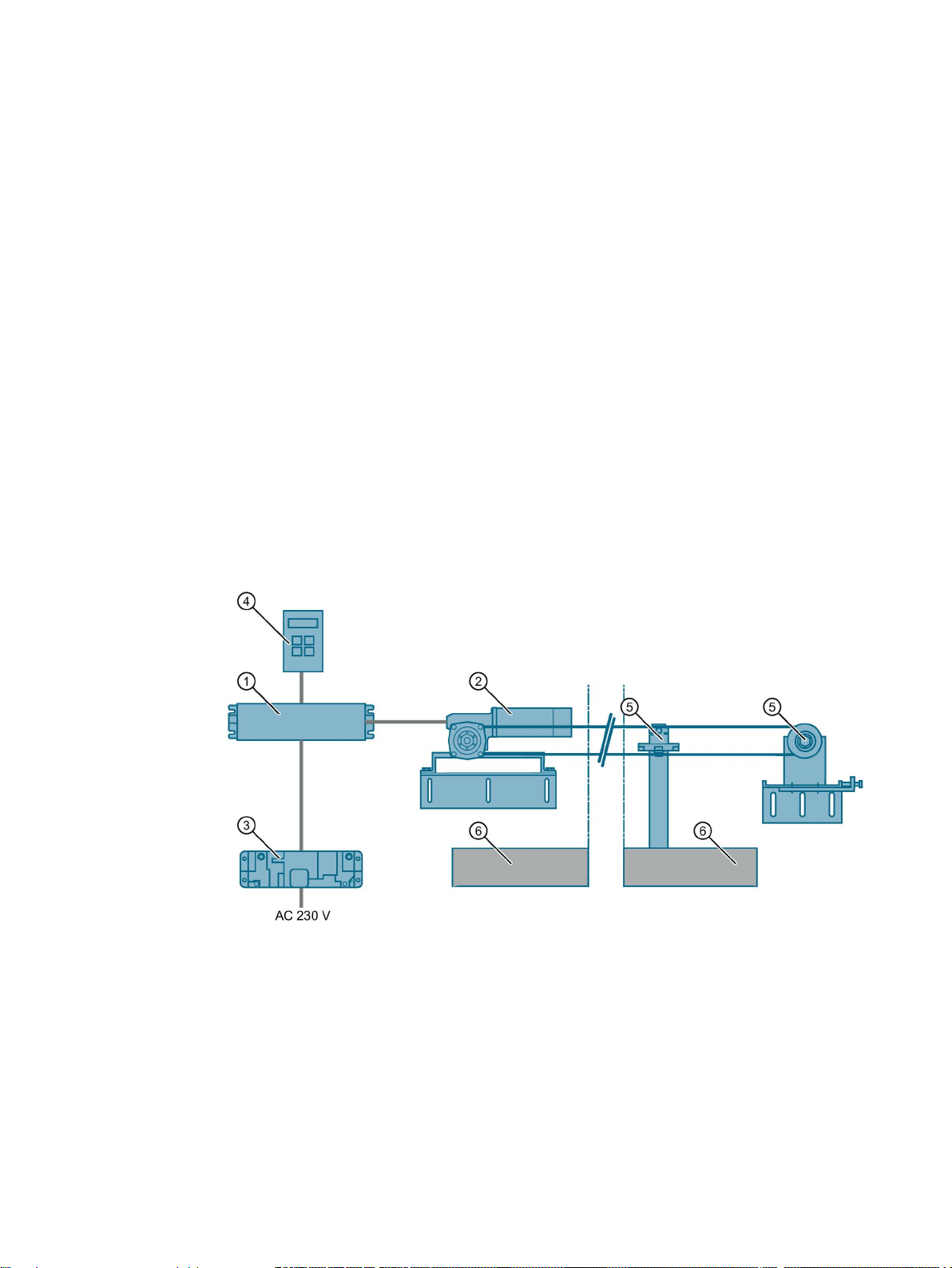
Overview of the product family
①
④
Software Kit)
②
Geared motor
⑤
Accessories
③
Power supply
⑥
Sliding door
Door control system is the general term for a controller of an access system.
The SIDOOR product family is primarily intended for operating sliding doors. Different
versions of SIDOOR controllers enable both horizontal and vertical doors to be operated.
Door control systems are characterized by the fact that there are always two defined states:
namely for the open and closed positions of the door. The door is always controlled between
these two positions in accordance with the guidelines of the respective application.
In a defined learn run initiated by "one-button operation", the door system independently
determines the values for the door width, the dynamic door weight and the drive direction of
the geared motor, and stores these data in a non-volatile memory.
Controller
Optional additional unit (e.g. SIDOOR Service Tool, SIDOOR
Image 3-1 System setup
AT40, ATD400V, ATD400K, ATD4xxW, ATD400S, ATE250S, ATD400T
System Manual, 06/2016, A2B00096162-AN
17

Product family
Technologies
DC technology
EC technology
DC technology
EC technology
Controllers
SIDOOR ATD400V ✓ —
SIDOOR ATD400K ✓ —
SIDOOR ATD400W ✓ —
SIDOOR ATD4xxW ✓ —
SIDOOR ATD400S ✓ —
SIDOOR ATE250S — ✓
SIDOOR ATD400T ✓ —
Geared motors
SIDOOR M2 ✓ —
SIDOOR M3 ✓ —
SIDOOR MDG180 ✓ —
DIN EN 45545-2
SIDOOR MEG250 — ✓
SIDOOR M4 ✓ —
SIDOOR MDG400 NMS
✓
—
SIDOOR MDG400 ✓ —
SIDOOR M5 ✓ —
Two different technologies are used in SIDOOR door control systems:
●
DC systems are two-phase driven, and have internal commutating brushes.
●
EC systems are three-phase driven, and are electronically commutated.
SIDOOR controllers and SIDOOR motors use the technologies as shown below:
Table 3- 1 Overview of technologies used
SIDOOR AT40 ✓ —
SIDOOR MDG180
AT40, ATD400V, ATD400K, ATD4xxW, ATD400S, ATE250S, ATD400T
✓ —
18 System Manual, 06/2016, A2B00096162-AN

Product family
3.1
Products
3.1.1
Controllers
Versions
Controller
Article No.
Description
Elevators
Industrial applications
3.1 Products
Controllers are electronic controllers connected to the power supply via an external power
supply unit (SIDOOR NT40, SIDOOR Transformer). They are generally connected to the
higher-level controller via digital or fieldbus interfaces, and can be configured via a user
interface.
The controllers are designed for different areas of application. The following table provides
an overview of the available controllers.
SIDOOR AT40 RELAY 6FB1111-0AT10-3AT2
SIDOOR AT40 CAN 6FB1111-1AT10-3AT3
SIDOOR ATD400V RELAY 6FB1111-1AT10-3VE2
SIDOOR ATD400K RELAY LB 6FB1141-1AT10-3KU2
SIDOOR ATD400K RELAY RC 6FB1141-1AT11-3KU2
SIDOOR ATD401W 6FB1141-1AT11-3WE2
• Controller for horizontal elevator doors, up to 600 kg door
weight
• Relay module
• Controller for horizontal elevator doors, up to 600 kg door
weight
• Serial interface to the higher-level controller (CAN mod-
ule)
• Controller for rising gate and rolling shutter doors in the
elevator field of application, up to 400 kg door weight
• Relay module
• Controller for cold room gates, up to 400 kg door weight
• 1 DI for light barriers (LB)
• Relay module
• Controller for cold room gates, up to 400 kg door weight
• 1 DI for reed contact (RC)
• Relay module
• Controller for machine tools, up to 600 kg door weight
• Relay module
AT40, ATD400V, ATD400K, ATD4xxW, ATD400S, ATE250S, ATD400T
System Manual, 06/2016, A2B00096162-AN
19

Product family
Controller
Article No.
Description
Railways
Platform screen doors
Interior railway doors
3.1 Products
SIDOOR ATD410W 6FB1141-4AT10-3WE2
SIDOOR ATD420W 6FB1141-2AT10-3WE2
SIDOOR ATD430W 6FB1141-3AT10-3WE2
SIDOOR ATD400S 6FB1131-0BM10-3AT3
SIDOOR ATE250S 6FB1231-0BM10-0AT3
• Controller for machine tools, up to 600 kg door weight
• USS bus interface to the higher-level controller (USS
module)
• Controller for machine tools, up to 600 kg door weight
• PROFIBUS interface to the higher-level controller
(PROFIBUS module)
• Controller for machine tools, up to 600 kg door weight
• PROFINET interface to the higher-level controller
(PROFIBUS module)
• Controller for platform screen doors, up to 400 kg door
weight
• Serial interface to the higher-level controller via the
SIDOOR AT-EB expansion unit
• Controller for platform screen doors, up to 250 kg door
weight
• Serial interface to the higher-level controller via the
SIDOOR AT-EB expansion unit
SIDOOR ATD400T RELAY 6FB1121-0BM13-3AT2
• Controller for interior railway doors, up to 400 kg door
weight
• Relay module
AT40, ATD400V, ATD400K, ATD4xxW, ATD400S, ATE250S, ATD400T
20 System Manual, 06/2016, A2B00096162-AN

Product family
3.1.2
Geared motors
Versions
Geared motor
Article No.
Description
3.1 Products
Geared motors form the maintenance-free drive unit in the door drive. The geared motors
feature DC motors with non-self-locking gearing and are speed-controlled. The set force and
speed limits are not exceeded.
The power is transmitted by a gear rack or chain. Toothed belts or chains pass over a
deflector pulley, and can be fitted with 2 clutch holders. This enables it to drive both singlesided and centrally-opening doors.
SIDOOR M2 L 6FB1103-0AT10-5MA0
SIDOOR M2 R 6FB1103-0AT11-5MA0
SIDOOR M3 L 6FB1103-0AT10-4MB0
SIDOOR M3 R 6FB1103-0AT11-4MB0
SIDOOR MDG180 L 6FB1103-0AT14-4MB0
SIDOOR MDG180 R 6FB1103-0AT13-4MB0
SIDOOR MDG180 L
DIN EN 45545-2
SIDOOR MDG180 R
DIN EN 45545-2
SIDOOR MEG250 L 6FB1233-0BM00-0MP0
SIDOOR MEG250 R 6FB1233-0BM01-0MP0
6FB1103-0AT16-4MB0
6FB1103-0AT15-4MB0
• Geared motor, pinion left, max. 120 kg door weight
• Cable length 1.5 m
• Geared motor, pinion right, max. 120 kg door weight
• Cable length 1.5 m
• Geared motor, pinion left, max. 180 kg door weight
• Cable length 1.5 m
• Geared motor, pinion right, max. 180 kg door weight
• Cable length 1.5 m
• Geared motor, pinion left, max. 180 kg door weight
• Without cable*
• Geared motor, pinion right, max. 180 kg door weight
• Without cable*
• Geared motor, pinion left, max. 180 kg door weight
• Cable length 1.5 m
• Geared motor, pinion right, max. 180 kg door weight
• Cable length 1.5 m
• Electronically commutated geared motor, pinion left, max.
250 kg door weight
• Cable length 1.5 m
• Electronically commutated geared motor, pinion right,
max. 250 kg door weight
• Cable length 1.5 m
AT40, ATD400V, ATD400K, ATD4xxW, ATD400S, ATE250S, ATD400T
System Manual, 06/2016, A2B00096162-AN
21

Product family
Geared motor
Article No.
Description
3.1 Products
SIDOOR M4 L 6FB1103-0AT10-3MC0
SIDOOR M4 R 6FB1103-0AT11-3MC0
SIDOOR MDG400 L 6FB1103-0AT14-3MC0
SIDOOR MDG400 R 6FB1103-0AT13-3MC0
SIDOOR M5 L 6FB1103-0AT10-3MD0
SIDOOR M5 R 6FB1103-0AT11-3MD0
SIDOOR MDG400 NMS L 6FB1103-0AT14-3MC1
SIDOOR MDG400 NMS R 6FB1103-0AT13-3MC1
* Cable can be ordered: See Section Accessories (Page 23)
• Geared motor, pinion left, max. 400 kg door weight
• Cable length 1.5 m
• Geared motor, pinion right, max. 400 kg door weight
• Cable length 1.5 m
• Geared motor, pinion left, max. 400 kg door weight
• Without cable*
• Geared motor, pinion right, max. 400 kg door weight
• Without cable*
• Geared motor, pinion left, max. 600 kg door weight
• Cable length 1.5 m
• Geared motor, pinon right, max. 600 kg door weight
• Cable length 1.5 m
• Geared motor, without pinion, max. 400 kg door weight
• Without cable*
• Geared motor, without pinion, max. 400 kg door weight
• Without cable*
AT40, ATD400V, ATD400K, ATD4xxW, ATD400S, ATE250S, ATD400T
22 System Manual, 06/2016, A2B00096162-AN

Product family
3.1.3
Accessories
Accessories
Article No.
Description
motor is mounted
SIDOOR deflector pulley
6FB1104-0AT04-0AS0
Deflector pulley for deflecting the SIDOOR toothed belt
3.1 Products
SIDOOR rubber-metal antivibration mount
SIDOOR mounting bracket 6FB1104-0AT01-0AS0 Mounting bracket for mounting the SIDOOR rubber-metal
SIDOOR deflector unit 6FB1104-0AT03-0AS0
SIDOOR door clutch holder 6FB1104-0AT01-0CP0
SIDOOR toothed belt 6FB1104-0AT01-0AB0
6FB1104-0AT01-0AD0
6FB1104-0AT02-0AD0
6FB1104-0AT02-0AS0
6FB1104-0AT02-0CP0
6FB1104-0AT02-0AB0
6FB1104-0AT03-0AB0
6FB1104-0AT04-0AB0
• Rubber-metal anti-vibration mount for quiet operation of
the door drive system
• Recommended for mounting SIDOOR M4 R / L, MDG400
R / L, M5 R / L and MDG400 NMS R / L geared motors
• Rubber-metal anti-vibration mount for quiet operation of
the door drive system
• Recommended for mounting SIDOOR M2 R / L, M3 R / L,
MDG180 R / L, MDG180 R / L DIN EN 45545-2 and
MEG250 R / L geared motors
anti-vibration mount on which, in turn, a SIDOOR geared
• Mounting bracket with tensioning device for deflector
pulley
• For mounting the SIDOOR deflector unit and for tension-
ing the SIDOOR toothed belt
• Deflector unit with deflector pulley
• For deflecting the SIDOOR toothed belt in the same
height and depth, aligned with motor drive pinion
• Door clutch holder for 12 mm-wide toothed belt
• For attaching both ends of the toothed belt, and for con-
necting the respective door panel to the toothed belt
• Door clutch holder for 14 mm wide toothed belt
• For attaching both ends of the toothed belt, and for con-
necting the respective door panel to the toothed belt
• Single-toothed STS
• Super Torque toothed belt
• Length 4 m, width 12 mm.
• Single-toothed STS
• Super Torque toothed belt
• Length 45 m, width 12 mm.
• Single-toothed STS
• Super Torque toothed belt
• Length 4 m, width 14 mm.
• Single-toothed STS
• Super Torque toothed belt
• Length 55 m, width 14 mm.
AT40, ATD400V, ATD400K, ATD4xxW, ATD400S, ATE250S, ATD400T
System Manual, 06/2016, A2B00096162-AN
23

Product family
Accessories
Article No.
Description
3.1 Products
SIDOOR
CABLE-RS485-MM-2m
SIDOOR
CABLE-RS485-MM-5m
SIDOOR
CABLE-RS485-MM-10m
SIDOOR CABLE AT-EB USB 6FB1124-0BM03-0CB0
SIDOOR CABLE-MDG-0.5m 6FB1104-0AT00-0CB5
SIDOOR CABLE-MDG-1.5m 6FB1104-0AT01-0CB5
SIDOOR CABLE-MDG-5m 6FB1104-0AT05-0CB0
SIDOOR CABLE-MDG-7m 6FB1104-0AT07-0CB0
SIDOOR CABLE-MDG-10m 6FB1104-0AT10-0CB0
SIDOOR CABLE-MDG-15m 6FB1104-0AT15-0CB0
6FB1124-0BM00-0CB0
6FB1124-0BM01-0CB0
6FB1124-0BM02-0CB0
• Cable from the SIDOOR AT-EB expansion unit to the
SIDOOR ATD400S
(Can also be used to connect the SIDOOR AT-EB expansion unit to the SIDOOR ATE250S)
• Cable length 2 m
• Cable from the SIDOOR AT-EB expansion unit to the
SIDOOR ATD400S
(Can also be used to connect the SIDOOR AT-EB to the
SIDOOR ATE250S)
• Cable length 5 m
• Cable from the SIDOOR AT-EB expansion unit to the
SIDOOR ATD400S
(Can also be used to connect the SIDOOR AT-EB expansion unit to the SIDOOR ATE250S)
• Cable length 10 m
• Programming cable to connect the USB adapter of the
SIDOOR Software Kit to the AT-EB
• Cable length 2 m
• Cable for connecting SIDOOR MDG180 R / L, MDG400 R
/ L / MDG400 NMS geared motors to SIDOOR ATD4xxW
controllers
• Cable length 0.5 m
• Cable for connecting SIDOOR MDG180 R / L, MDG400 R
/ L / MDG400 NMS geared motors to SIDOOR ATD4xxW
controllers
• Cable length 1.5 m
• Cable for connecting SIDOOR MDG180 R / L, MDG400 R
/ L / MDG400 NMS geared motors to SIDOOR ATD4xxW
controllers
• Cable length 5 m
• Cable for connecting SIDOOR MDG180 R / L, MDG400 R
/ L / MDG400 NMS geared motors to SIDOOR ATD4xxW
controllers
• Cable length 7 m
• Cable for connecting SIDOOR MDG180 R / L, MDG400 R
/ L / MDG400 NMS geared motors to SIDOOR ATD4xxW
controllers
• Cable length 10 m
• Cable for connecting SIDOOR MDG180 R / L, MDG400 R
/ L / MDG400 NMS geared motors to SIDOOR ATD4xxW
controllers
• Cable length 15 m
AT40, ATD400V, ATD400K, ATD4xxW, ATD400S, ATE250S, ATD400T
24 System Manual, 06/2016, A2B00096162-AN

Product family
Accessories
Article No.
Description
controller
cable
higher-level SIMATIC controller
controllers
3.1 Products
SIDOOR CABLE-MDG-20m 6FB1104-0AT20-0CB0
PROFIBUS FC bus connector
RS 485
PROFIBUS FC Standard Cable
GP
IE FC RJ45 plug 180 4X2 6GK1901-1BB11-2AB0 Plug connector with axial cable outlet (180°) for connecting
IE FC TP Standard Cable GP 6XV1878-2A Cable for connecting the SIDOOR ATD430W controller to the
DIN rail holder 6FB1144-0AT00-3AS0 DIN rail holder with fixing screws for SIDOOR ATD4xxW
6GK1500-0FC10 Bus connector with axial cable outlet (180°, 20m) for connect-
6XV1830-0EH10 PROFIBUS cable for connecting SIDOOR ATD410W and
• Cable for connecting SIDOOR MDG180 R / L, MDG400 R
/ L / MDG400 NMS geared motors to SIDOOR ATD4xxW
controllers
• Cable length 20 m
ing SIDOOR ATD410W and SIDOOR ATD420W controllers
to the USS / PROFIBUS bus cable
SIDOOR ATD420W controllers to the higher-level SIMATIC
the SIDOOR ATD430W controller to the PROFINET bus
You will find more accessories in the Industry Mall (http://www.siemens.com/siplus/mall)
AT40, ATD400V, ATD400K, ATD4xxW, ATD400S, ATE250S, ATD400T
System Manual, 06/2016, A2B00096162-AN
25
Product family
3.1.4
Power supply
Device selection
Power supply
Article No.
Description
SIDOOR NT40
6FB1112-0AT20-3PS0
SIDOOR Transformer
6FB1112-0AT20-2TR0
DC voltage supply (Page 276)
-
3.1 Products
SIDOOR power supplies connect the controllers to the respective application-specific power
supply.
Power supply for controllers without an integrated power
supply unit.
AT40, ATD400V, ATD400K, ATD4xxW, ATD400S, ATE250S, ATD400T
26 System Manual, 06/2016, A2B00096162-AN
Product family
3.1.5
Optional additional units
Selection of additional units
Additional unit
Article No.
Description
2.
control systems via the proprietary RS 485 interface.
data and the current firmware version.
3.1 Products
Additional units meet a range of customer requirements in order to ensure the universal
implementation and maintenance of the system.
The additional units are easy to connect to a deenergized controller via the interfaces
provided – and are available for use as soon as the power supply is connected.
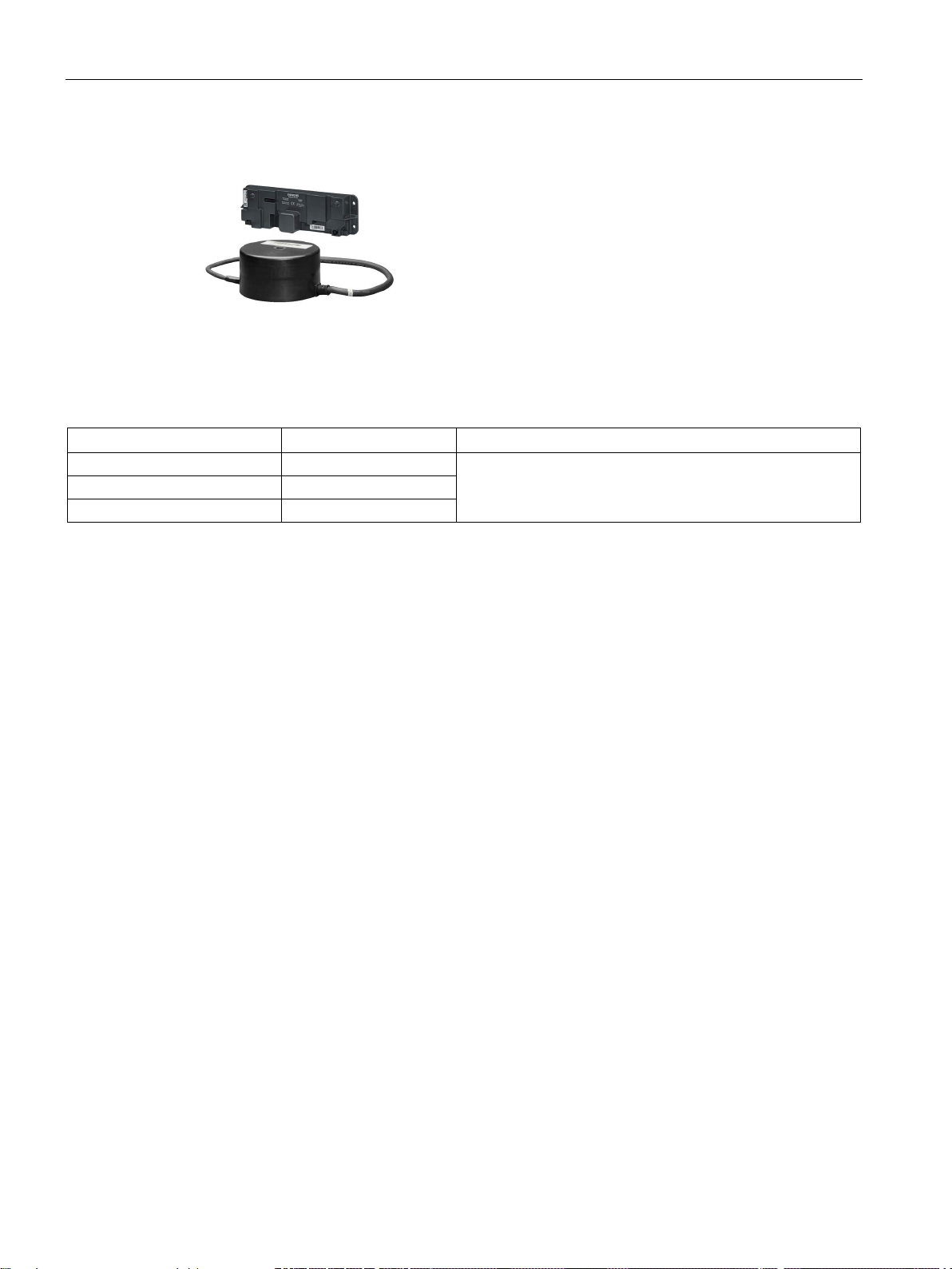
SIDOOR EMC FILTER 6FB1104-0AT20-0AT0 A line filter must be installed in the DC power supply to the
SIDOOR ATD400T RELAY controller to comply with the EMC
requirements for emitted interference set out in EN 50121-3-
SIDOOR AT-EB expansion unit
(with FW1.10)
SIDOOR Service Tool 6FB1105-0AT01-6ST0 The SIDOOR Service Tool may be used to input door com-
6FB1135-2BM10-0CP0 The SIDOOR AT-EB expansion unit enables SIDOOR con-
trollers to be connected via a PROFIBUS DP interface, and
makes additional input and output signals available.
The SIDOOR AT-EB expansion unit controls up to two door
mands, to change drive parameters and to read the learnt
parameters, door states, input and output signals, service
AT40, ATD400V, ATD400K, ATD4xxW, ATD400S, ATE250S, ATD400T
System Manual, 06/2016, A2B00096162-AN
27

Product family
3.1.6
Software
Selection
Software
Article No.
Description
3.1 Products
The optional SIDOOR Software Kit facilitates user-friendly operation and detailed diagnostics
via a PC.
SIDOOR Software Kit 6FB1105-0AT01-6SW0 The package includes the following components:
• Installation CD (Software Kit)
– Sidoor User Software
– Siemens HCS12 Firmware Loader
– Sidoor USB to UART Bridge driver
– License provisions
– SIDOOR Software Kit Operating Instructions
• 1 x USB adapter
• 1 x USB connecting cable
• 1x D-SUB connecting cable (9-pin, plug/socket)
• 1x D-SUB connecting cable (9-pin, socket/socket)
The contents of the SIDOOR Software Kit installation CD are also available as an Installation
package (http://support.automation.siemens.com/WW/view/en/92418945) from Industry
Online Support.
You can find more information about the SIDOOR Software Kit in the SIDOOR Software Kit
Operating Instructions (http://support.automation.siemens.com/WW/view/en/92711247).
AT40, ATD400V, ATD400K, ATD4xxW, ATD400S, ATE250S, ATD400T
28 System Manual, 06/2016, A2B00096162-AN

4
4.1
Elevators
SIDOOR AT40
SIDOOR ATD400V
SIDOOR door drives are drives for doors and gates in various areas of application. The
controllers are optimally configured for their areas of application.
The following controllers are offered for elevator applications:
●
The comfort SIDOOR AT40 elevator door drive is an "intelligent" door drive with which
cabin and shaft doors can be opened and closed at adjustable speeds and accelerations.
●
The SIDOOR ATD400V hoisting and rolling shutter drive for elevators is an "intelligent"
door drive for the operation of vertical door systems on elevators.
AT40, ATD400V, ATD400K, ATD4xxW, ATD400S, ATE250S, ATD400T
System Manual, 06/2016, A2B00096162-AN
29

Areas of application
4.2
Industrial applications
Industrial applications
SIDOOR ATD400K
SIDOOR ATD4xxW
SIDOOR ATD401W
SIDOOR ATD410W
USS bus
SIDOOR ATD420W
PROFIBUS DP
SIDOOR ATD430W
PROFINET IO
4.2 Industrial applications
We offer the following controllers for industrial applications:
●
The SIDOOR ATD400K RELAY LB and SIDOOR ATD400K RELAY RC industrial door
drives offer the optimal drive solutions for cold room gates weighing up to 400 kg. The
ATD400K RELAY LB model enables the connection of light barriers with "LB" logic, and
the ATD400K RELAY RC model enables the direct connection of a cord-operated switch
to open the gate.
Both drives meet the requirements of EN ISO 13849-1:2008 with regard to safety of
machinery and EN 12453:2000, section 5.2 with regard to safety in use of power
operated doors.
●
ATD4xxW machine tool door drives are "intelligent" door drives that can be used to
operate protective doors on machine tools. The safe functions - force limitation, energy
limitation and end position detection - fulfill the requirements according to
DIN EN ISO 13849-1:2008 for Category 2 and Performance Level d. The drives are
suitable for power-operated guards according to EN 953:1997+A1:2009 Section 5.2.5.2
"Actuating forces".
The SIDOOR ATD4xxW door controller enables connection to diverse fieldbus systems.
This makes integration into the industrial//Simatic environment possible. PROFINET IO,
PROFIBUS DP and USS are currently specified as fieldbuses. The PROFIBUS "variablespeed drives" profile is generally used as the higher-level device profile.
–
The "offline" relay variant can be used for simple automation tasks. As there is no
possibility of interfacing to a bus, it provides a limited scope of functions.
–
The controller is interfaced to a
You can find more detailed information about the USS protocol online at Industry
Online Support (http://support.automation.siemens.com/WW/view/de/24178253/0/en).
–
The
(AT-PB). This is an intelligent module that comes with its own firmware.
interface is realized by means of a modular PROFIBUS module
by means of a modular USS module.
–
The
(AT-PN). This is an intelligent module that comes with its own firmware.
AT40, ATD400V, ATD400K, ATD4xxW, ATD400S, ATE250S, ATD400T
30 System Manual, 06/2016, A2B00096162-AN
interface is realized by means of a modular PROFINET module
Loading...