

Siemens SIDOOR AT12 User Manual
Answers for industry.
Products for specific requirements
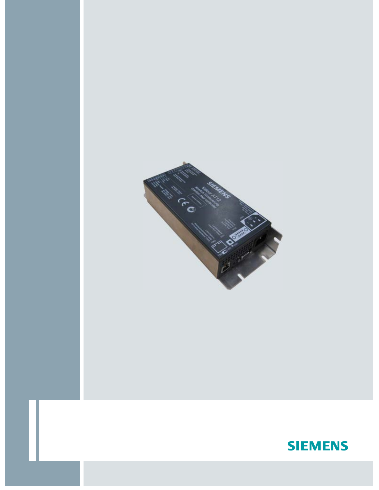
SIDOOR
Elevator door drive AT12
Manual · 02/2012

Elevator door drive AT12
_
_________________
_
_
_________________
_
_
_________________
_
_
__________________
_
_________________
_
_
_________________
_
_
_________________
_
_
_________________
_
_
_________________
_
_
_________________
_
_
_________________
_
_
_________________
_
_
__________________
Introduction
1
Safety notes
2
Definitions
3
Products for specific requirements
Overview of controls
4
SIDOOR
Functions and device
responses
5
Mechanical installation and
setting
6
Elevator door drive AT12
Manual
Electric adjustment and
commissioning
7
The relay contacts
8
CAN
9
Travel curve
10
11
Operating status display
12
Technical data
Appendix
A
02/2012
A2B00086683A-04
Legal information
Legal information
Warning notice system
This manual contains notices you have to observe in order to ensure your personal safety, as well as to prevent
damage to property. The notices referring to your personal safety are highlighted in the manual by a safety alert
symbol, notices referring only to property damage have no safety alert symbol. These notices shown below are
graded according to the degree of danger.
DANGER
indicates that death or severe personal injury will result if proper precautions are not taken.
WARNING
indicates that death or severe personal injury may result if proper precautions are not taken.
CAUTION
with a safety alert symbol, indicates that minor personal injury can result if proper precautions are not taken.
CAUTION
without a safety alert symbol, indicates that property damage can result if proper precautions are not taken.
NOTICE
indicates that an unintended result or situation can occur if the relevant information is not taken into account.
If more than one degree of danger is present, the warning notice representing the highest degree of danger will
be used. A notice warning of injury to persons with a safety alert symbol may also include a warning relating to
property damage.
Qualified Personnel
The product/system described in this documentation may be operated only by personnel qualified for the specific
task in accordance with the relevant documentation, in particular its warning notices and safety instructions.
Qualified personnel are those who, based on their training and experience, are capable of identifying risks and
avoiding potential hazards when working with these products/systems.
Proper use of Siemens products
Note the following:
WARNING
Siemens products may only be used for the applications described in the catalog and in the relevant technical
documentation. If products and components from other manufacturers are used, these must be recommended
or approved by Siemens. Proper transport, storage, installation, assembly, commissioning, operation and
maintenance are required to ensure that the products operate safely and without any problems. The permissible
ambient conditions must be complied with. The information in the relevant documentation must be observed.
Trademarks
All names identified by ® are registered trademarks of Siemens AG. The remaining trademarks in this publication
may be trademarks whose use by third parties for their own purposes could violate the rights of the owner.
Disclaimer of Liability
We have reviewed the contents of this publication to ensure consistency with the hardware and software
described. Since variance cannot be precluded entirely, we cannot guarantee full consistency. However, the
information in this publication is reviewed regularly and any necessary corrections are included in subsequent
editions.
Siemens AG A2B00086683A-04 Copyright © Siemens AG 2012.
Industry Sector Ⓟ 02/2012 Technical data subject to change All rights reserved
Postfach 48 48
90026 NÜRNBERG
GERMANY

Table of contents
1 Introduction................................................................................................................................................ 7
2 Saf
ety notes............................................................................................................................................... 9
2.1 General safety inst
ructions ............................................................................................................9
3 Definit
ions................................................................................................................................................ 11
4 Overvie
w of controls ................................................................................................................................ 13
5 Function
s and device responses ............................................................................................................. 15
5.1 Learn and test run........................................................................................................
................15
5.2 DOOR OPEN command .........................................................................................................
.....15
5.3 DOOR CLOSE command
............................................................................................................15
5.4 Learn run button..........................................................................................................
.................16
5.5 Parameter settings.......................................................................................................................16
5.6
Blockage detection "CLOSE"................................................................................................
.......17
5.7 Blockage detection "OPEN".........................................................................................................17
5.8
Nudge...........................................................................................................................................17
5.9
Restart after
power failure............................................................................................................17
5.10 Closi
ng force ................................................................................................................................18
5.11 Emergency release
......................................................................................................................18
5.12 Ove
rload protection......................................................................................................................19
6 Mechanical i
nstallation and setting .......................................................................................................... 21
7 Electric adjustment and c
ommissioning................................................................................................... 23
8 The relay con
tacts ................................................................................................................................... 27
9 CAN..........................................................
............................................................................................... 29
10 Travel
curve............................................................................................................................................. 31
11 Operating stat
us display .......................................................................................................................... 33
11.1 Speed limit curve ........................................................................................................
.................34
12 Technical
data ......................................................................................................................................... 35
12.1 DC geared motor ..........................................................................................................
...............35
12.2 Control unit...................................................................................................................................35
12.3
Regulations and s
tandards ..........................................................................................................35
Elevator door drive AT12
Manual, 02/2012, A2B00086683A-04
5

Table of contents
Elevator door drive AT12
6 Manual, 02/2012, A2B00086683A-04
A Appendix.................................................................................................................................................. 37
A.1 Order nos. of the individual parts................................................................................................ 37
A.2 Dimension drawing of AT12 controller
........................................................................................ 38
A.3 24 V geared motor with r
ubber-metal anti-vibration mount and mounting bracket..................... 39
A.4 Deflector pull
ey with tensioning device and mounting bracket ................................................... 40
A.5 Door clutc
h holder....................................................................................................................... 41
A.6 Asse
mbly suggestion .................................................................................................................. 42
A.7 Terminal circuit diagram of c
ontrol inputs ................................................................................... 43
A.8 Diagnostics
and parameterization............................................................................................... 44
A.9 Settings record
............................................................................................................................ 45

Introduction
1
The comfort elevator door drive AT12 is an "intelligent" door drive with which the cabin and
shaft doors can be opened and closed at adjustable speeds and accelerations. This
maintenance-free drive unit consists of a speed-controlled DC motor with non-self-locking
gearing. The power is transmitted by a toothed belt. The toothed belt passes over a deflector
pulley, and can be fitted with two clutch holders. This enables it to drive both single-sided
and centrally-opening doors.
The AT12 is currently supplied with the following motor:
– 24 V / 1.8 A motor, suitable for a maximum total door panel weight of 120 kg
The door drive can be ordered with the drive pinion either on the left or right-hand side,
please see the drawing in the Appendix.
Operation of the door drive does not require limit switches.
The door width and the
"OPEN"
and
"CLOSED"
positions are determined automatically.
An LED display on the controller indicates the current operating states.
The Appendix includes all the important dimension drawings, an assembly suggestion, and
the identification numbers for ordering the individual drive components.
Note
For reasons of clarit
y, these operating instructions do not contain complete, detailed
information about all product types. Similarly, they cannot cover every conceivable type of
installation, operation or maintenance.
Additional information about this product and its application can be found in the Internet
(www.siemens.com/sidoor
).
Furthermore, the contents of these Operating Instructions shall not become a part of or
modify any prior or existing agreement, commitment, or legal relationship. The sales contract
contains the entire obligation of SIEMENS. The warranty contained in the contract between
the parties is the sole warranty of SIEMENS. Any statements contained in these operating
instructions neither expand nor restrict the scope of these contractual warranty conditions.
Elevator door drive AT12
Manual, 02/2012, A2B00086683A-04
7

Introduction
Elevator door drive AT12
8 Manual, 02/2012, A2B00086683A-04
Safety notes
2
Before commissioning
Please read through these instructions carefully. They contain essential information for the
installation, use and safety of the equipment.
2.1 General safety instructions
WARNING
Only appropriately qualified personnel should work on or in the vicinity of this equipment.
Personnel must be thoroughly familiar with all the warnings, notices, and functions of the
AT12 door controller described in the operating instructions.
In the context of the operating instructions and warning notices, a
qualified person
is a
person who is familiar with assembling, installing, commissioning, and operating the product,
and who has the relevant qualifications, such as:
● Training, instruction or authorization to commission electric circuits and devices/systems
in compliance with safety engineering standards.
● Training or instruction in the maintenance and use of appropriate safety equipment in
compliance with safety engineering standards.
● Training in first aid measures
The successful and safe operation of this equipment is dependent on proper transportation,
storage, installation, and assembly, as well as on careful operation and maintenance.
Before commissioning, all electrical connections must be inspected to ensure that all
contacts are secure.
Before starting work on the door drive, it must be disconnected from the power supply by
unplugging the power plug.
Elevator door drive AT12
Manual, 02/2012, A2B00086683A-04
9

Safety notes
2.1 General safety instructions
Elevator door drive AT12
10 Manual, 02/2012, A2B00086683A-04

3
Definitions
Initial speed
Reduced speed in the opening and closing directions after power on until normal operation is
detected.
Creep speed
Reduced speed in the vicinity of the OPEN position of the elevator door (creep distance).
Cutter speed
Reduced speed in the vicinity of the CLOSED position of the elevator door (cutter distance).
Creep distance
Range of door travel in the vicinity of the OPEN position.
Cutter distance
Range of door travel in the vicinity of the CLOSED position.
Elevator door drive AT12
Manual, 02/2012, A2B00086683A-04
11

Definitions
Elevator door drive AT12
12 Manual, 02/2012, A2B00086683A-04
4
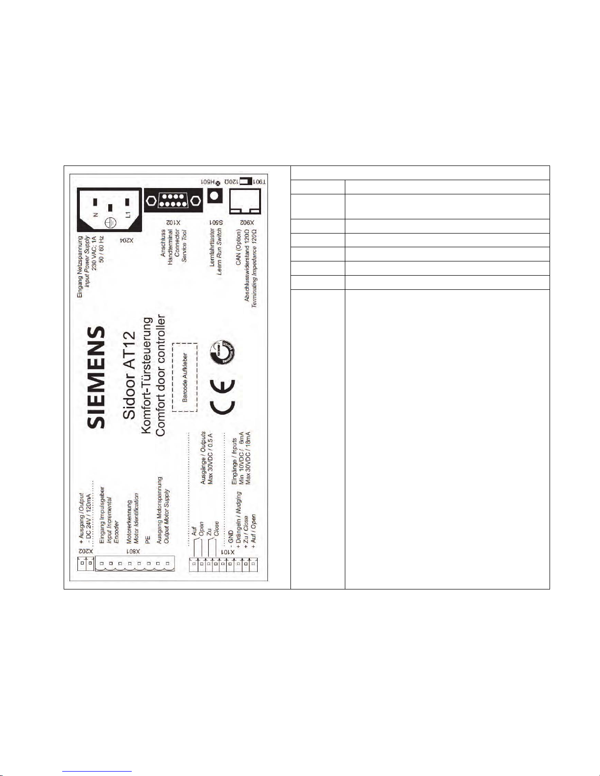
Overview of controls
Sidoor AT12:
X204: Mains connection 230 V (1 A, 50 / 60 Hz)
X102: Connector for Service Tool and USB adapter
(Software Kit)
S501: Learn run button
X902: CAN connector (CAN OPEN RJ45)
T901: Switchable CAN terminating resistor 120 ohms
X202: Voltage output 24 VDC / 120 mA
X801: Motor plug
X101: Connector for output signals
• Open
• Closed
Connector for input signals:
• Nudge
• Close
• Open
Elevator door drive AT12
Manual, 02/2012, A2B00086683A-04
13

Overview of controls
Elevator door drive AT12
14 Manual, 02/2012, A2B00086683A-04

5
Functions and device responses
5.1 Learn and test run
Pressing the learn run button for more than five seconds
(S501)
executes the automatic
determination of the parameters:
1. Detection of the direction of door movement and the
"CLOSED"
position
2. Determination of the friction values of the door system and the weight of the door.
3. Determination of the door width and the
"OPEN"
position. Closure of the door until it has
traveled through the entire determined door width and reached the
"CLOSED"
position.
These parameters are then saved, which takes three seconds.
5.2 DOOR OPEN command
The
DOOR OPEN
command opens the door according to the set speed of travel curve as
long as the command is present.
The transitions along the speed of travel curve (e.g. from acceleration to constant velocity)
are smoothed to prevent noises possibly arising from the play between the cabin and shaft
doors. The door reaches the
"OPEN"
position at creep speed. Then, if the
DOOR OPEN
command is present, the door is held open with a reduced torque.
● The
DOOR OPEN
command must remain present throughout the entire opening
movement.
● The
DOOR OPEN
command must remain present continuously in order to maintain
continuous torque in the
OPEN
position.
The
DOOR OPEN
command has priority over all other control commands.
5.3 DOOR CLOSE command
The
DOOR CLOSE
command must remain present continuously in order to close the door.
After the door has closed, it is held in this position with reduced torque as long as the
DOOR
CLOSE
command remains present.
Elevator door drive AT12
Manual, 02/2012, A2B00086683A-04
15
 Loading...