

Siemens Sicore II Installation And Commissioning Manual
Sicore II
Sicore II Installation and
Commissioning Guide
Unrestricted
Jan 18
667/HB/52600/000
Issue 2

Contents
2
Contents
Contents 2
List of Figures 5
List of Tables 7
Change History 8
Health and Safety Protection 9
1. Introduction 11
1.1. Purpose 11
1.2. Contact Us 11
1.3. Document References 11
1.4. Abbreviations 12
1.5. Third Party Information 13
1.6. Trademarks 13
1.7. Static IP Address 13
1.8. Secure Disposal Instructions 13
1.9. Recycling and Disposal 14
2. Security Recommendations 15
2.1. Password Security 15
2.2. VPN 15
2.3. FTP 15
2.4. NTP 15
3. General 16
3.1. Product Overview 16
3.2. Product Features 17
3.3. Product Variants and Options 18
4. Prod u c t Fea t ures Descrip t i on 19
4.1. Serial Input / Output 19
4.1.1. Ethernet 19
4.1.2. RS232 19
4.1.3. RS422/RS485 19
4.2. Digit al Input / Output 19
4.2.1. Digital Inputs 19
Sicore II Installation and Commissioning Guide
667/HB/52600/000 Issue 2 Unrestricted

Contents
3
4.2.2. Digital Outputs 20
4.2.3. Power Swit ch 20
4.2.4. Relay Output 20
4.3. WiFi Interface 20
4.4. 3G/4G Inter face 21
4.5. GPS / Clock System 21
4.6. User Interface 22
4.6.1. System Status and Configuration 22
4.6.2. Terminal 22
4.6.3. Site Log 22
4.6.4. Fault T able 22
4.6.5. System Log 23
4.6.6. System 23
4.7. Firmwa re Update 24
5. System Components 25
5.1. System Block Diagram 25
5.2. Power Supply 26
5.3. Pole Mounted Power Supply Assembly 26
5.4. Fuses 28
5.5. Inbuilt Backup Battery 28
5.6. Rear Panel 29
5.6.1. Cable Connections 30
5.6.2. Main Connector 32
5.6.3. Aux 1 Connector 33
5.6.4. Aux 2 Connector 35
5.6.5. WiFi Antenna Connector 36
5.6.6. SIM Card Connector 36
5.6.7. Ear th Stud 38
5.6.8. Status LED 38
6. Installation 39
6.1. Pre-Requisites 39
6.1.1. Documentation 39
6.1.2. Qualifications 39
Sicore II Installation and Commissioning Guide
667/HB/52600/000 Issue 2 Unrestricted

Contents
4
6.1.3. Tools 40
6.2. Cabinet Access 40
6.3. Preparation 41
6.4. Cables 41
6.5. Mounting the S icore II Camera 42
6.6. Torque Settings 44
6.7. Lens Protective Label 44
6.8. Alignment 45
6.8.1. Alignment Proces s 45
7. Commissioning 57
7.1. Set site specific IP address 57
7.2. GPS Time Source 59
7.3. Colour Overview 62
7.4. Monochrome O verview 63
7.5. Camera Calibration 64
7.6. Region Of Interest - ROI 67
7.7. ANPR Engine 69
7.8. Result Creation 70
7.9. Simple Uploader - CIFS 71
7.10. License Installation 74
8. Security 75
8.1. Web Interface Username an d Password 75
8.2. VPN 76
8.3. Open VPN Certificate 76
8.4. Open VPN Comms 77
9. Maintenance 78
10. Fault finding 79
A Appendix - Technical Specification 81
B Appendix - Part Numbers and Related Equipment 83
B.1 Main and Aux Connecting Cables 83
B.2 Mounting Kits 84
B.3 Power Supplies 84
C Appendix – Human Readable Part Number 85
Sicore II Installation and Commissioning Guide
667/HB/52600/000 Issue 2 Unrestricted

Contents
5
List of Figures
Figure 1 – Sicore II – Front View 16
Figure 2 – Wipe System Warning 23
Figure 3 – System Upgrade 24
Figure 4 – Sicore II System Overview 25
Figure 5 – Pole Mounted PSU Assembly 27
Figure 6 – Sicore II Rear Panel 29
Figure 7 – Cable Makeup 30
Figure 8 – Example screen clamp arrangement 31
Figure 9 – Main Connector Pin Arrangement 32
Figure 10 – Aux 1 Connector Pin Arrangement 34
Figure 11 – Aux 2 Connector Pin Arrangement 36
Figure 11 – Sicore II Protective Label 44
Figure 12 – Sicore II Basic Geometry – Top View – No Skew 46
Figure 13 – Sicore II Basic Geometry – Side View 46
Figure 1 4 – Sicore I I Basic Geometry – Top View – With Skew 47
Figure 15 – Distance D position at edge of road 51
Figure 1 6 – Reflective Puck – 3M 290 -W Road Stud 51
Figure 17 – Standard Sicore II Pan / Tilt / Roll Bracket 52
Figure 18 – Device Security Menu 53
Figure 19 – Username and Password Menu 54
Figure 20 – Home Screen 54
Figure 21 – Web Interface – Top Level Menu 55
Figure 22 - Plate rotation due to road camber 55
Figure 23 – Live View – Example Alignment 56
Figure 24 – DSL/Fibre Menu 58
Figure 25 – GPS Menu 59
Figure 26 – NTP Menu 60
Figure 27 – Sensors Menu 61
Figure 28 – GPS Status Menu 62
Figure 29 – Overview Menu 63
Figure 30 – Camera Calibration Menu 64
Sicore II Installation and Commissioning Guide
667/HB/52600/000 Issue 2 Unrestricted

Contents
6
Figure 31 – Camera Calibration – Positive Skew 66
Figure 32 – Camera Calibration – Negative Skew 66
Figure 33 – ROI 1 - Default 67
Figure 34 – ROI 2 Example 68
Figure 35 – ROI 3 Example 68
Figure 36 – ANPR Engine Country Modules 69
Figure 37 – Result Creation Menu 70
Figure 38 – System Menu 71
Figure 39 – Win 10 Share P ermissions 72
Figure 40 – Win 7 / 10 Folder Share 72
Figure 41 – Remote Filesystem Menu 73
Figure 42 – Security Menu 75
Figure 43 – Open VPN Vertificate 76
Figure 44 – Open VPN Comms 77
Sicore II Installation and Commissioning Guide
667/HB/52600/000 Issue 2 Unrestricted

List of Tables
7
List of Tables
Table 1 – Change History 8
Table 2 – External Document References 11
Table 3 – Abbreviations 12
Table 4 – Table of Base Variants 18
Table 5 – Table of Options 18
Table 6 – Power Supply Requirements 26
Table 7 – S iemens Approved Power Supplie s 26
Table 8 – Cable Cores 30
Table 9 – Main Connector Pinout 32
Table 10 – Aux 1 Connector Pinout 33
Table 11 – Aux 2 Connector Pinout 35
Table 12 – SIM card fitting 37
Table 13 – Mounting Kit Photos 43
Table 14 - Geometry Acronyms 48
Table 15 – Two lane Geometry 49
Table 16 – Three lane Geometry 50
Table 17 – F ault Finding 80
Table 18 – Main and Aux Cable Part Numbers 83
Table 19 – Mounting Kit Part Numbers 84
Table 20 – Power Supply Part Numbers 84
Sicore II Installation and Commissioning Guide
667/HB/52600/000 Issue 2 Unrestricted

Change History
8
Change History
Change History
Issue Change Reference Date
1 Formal Issue Nov 2017
2 Added Security Recommendations (Section 2), Appendix B and
Appendix C
Table 1 – Change History
Jan 2018
Sicore II Installation and Commissioning Guide
667/HB/52600/000 Issue 2 Unrestricted
Health and Safety Protection
9
Health and Safety Protection
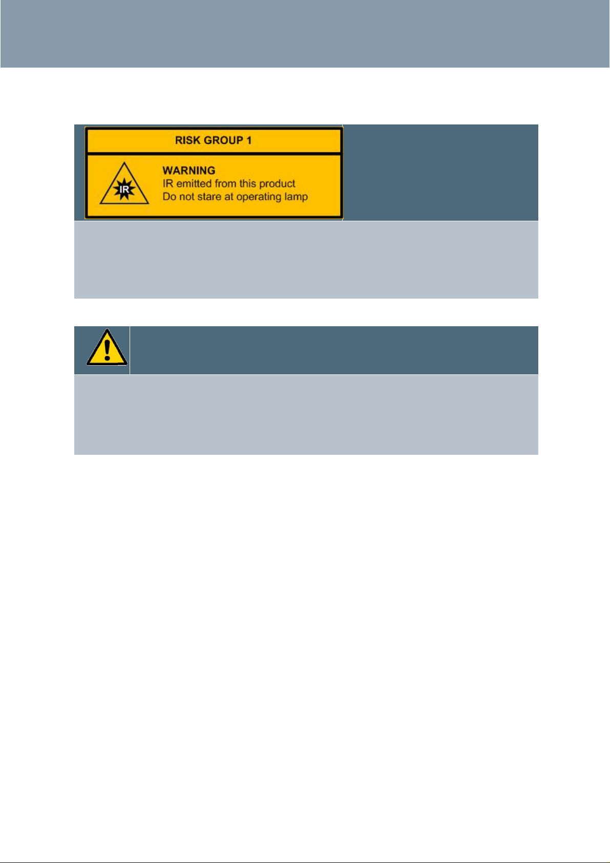
Safety IR IR Safety Warning
OPTICAL EMISSIONS OF THE SICORE II IR FLASH ARE IN EXCESS OF THE EXEMPT
GROUP, VIEWER-RELATED RISKS ARE DEPENDANT UPON HOW THE PRODUCT IS
INSTALLED AND USED
THIS PRODUCT IS CLASSIFIED AS RISK GROUP 1 AT A DISTANCE OF 298 mm
Safety of Installation and Maintenance Personnel
IT IS RECOMMENDED THAT DUE TO THE HAZARDS PRESENT WITHIN THE SICORE II CAMERA
THAT AL L POWER TO THE UNIT IS DISCONNECTED BEFORE WORKING ON THE UNIT. WHERE
A RISK ASSESSMENT AND METHOD STATEMENT FOR THE WORKS TO BE COMPLETED AND /
OR THE INSTRUCTIONS FOR THE OEM EQUIPMENT BEING INSTALLED OR REMOVED ALLOWS,
LIVE WORKING MAY BE CO NSIDERED.
Safety of Maintenance Personnel
In the interests of health and safety, when using or servicing this equipment the following
instructions must be noted and adhered to:
Only skilled or instructed personnel with relevant technical knowledge and experience,
who are also familiar with the safety procedures required when dealing with modern
electrical/electronic equipment are to be allowed to use and/or work on the equipment.
All work shall be performed in accordance with the Electricity at Work Regulations 1989
or the relevant local, state and government regulations.
Such personnel must take heed of all relevant notes, cautions and warnings in this
Handbook and any other Document or Handbook associated with the equipment
including, but not restricted to, the following:
The equipment must be correctly connected to the specified incomin g power supply.
The equipment must be disconnected / isolated from the incoming power supply before
removing any protective covers or working on any part from which the protective covers
have been removed.
Any power tools must be regularly inspected and tested.
Any ladders used must be inspected before use to ensure they are sound and not damaged .
Sicore II Installation and Commissioning Guide
667/HB/52600/000 Issue 2 Unrestricted

Health and Safety Protection
10
When using a ladder, before climbing it, ensure that it is erected properly and is not liable to
collapse or move. If using a ladder near a carriageway, ensure that the area is properly
coned and signed.
Any personnel working on site must wear the appropriate protective clothing, e.g. reflective
vests, etc.
The configuration process should only be carried out by persons who are adequately trained,
have a full understanding of the needs of the county or region were the unit is to be used
and are experienced in the tasks to be undertaken.
Safety of Road Users
It is important that all personnel are aware of the dangers to road users that could arise
during repair and maintenance of traffic control equipment.
Ensure that the working area is coned and signed as necessary to warn motorists and
pedestrians of any dangers and to help protect the personnel working on the site.
Safety Warning – Lithium Battery
This equipment contains a rechargeable Lithium Coin Cell.
This cell will last the lifetime of the equipment and is not designed to be changed.
Keep the unit between 0°C and 35°C for prolonged storage.
Sicore II Installation and Commissioning Guide
667/HB/52600/000 Issue 2 Unrestricted

Introduction
11
1. Introduction
1.1. Purpose
This handbook gives details of the facilities available in the Sicore II ANPR Camera and
describes the procedures for the Installation and Commissioning and provides guidance on
routine Maintenance and Fault Finding:
Sections 2 and 4 cover the general operation and product features.
Section 5 details the hardware components and connections.
Section 6 details the Installation process.
Section 7 details the Commissioning process.
Section 8 covers steps to ensure the product is secure
Section 9 covers maintenance.
Section 10 provides a basic fault finding guide
1.2. Contact Us
If you have any comments on this handbook or need any further information our contact
details are as follows:
Service Operations Centre
contacteng.stc@siemens.com
+44 845 1930004
1.3. Document References
External Document References
667/HB/52600/001 Sicore II Operating Instructions Handbook
667/HB/52600/002 Sicore II Interfaces Handbook
TR2523 Traffic Control Equipment Interfacing Specification
Table 2 – External Document References
Sicore II Installation and Commissioning Guide
667/HB/52600/000 Issue 2 Unrestricted

Introduction
12
1.4. Abbreviations
Abbreviations
AC Alternating Current
ANPR Automatic Number Plate Recognition
CIFS Common Internet File System
CTS Clear To Send
DC Direct Current
CPU Central Processing Unit
GPS Global Positioning System
I/O Input / Output
IR Infra Red
LED Light Emitting Diode
mA milliamps
ms milliseconds
NAS Network Attached Storage
NTP Network Tim e Protocol
OEM Original Equipment Manufacturer
PSU Power Supply Unit
RTS Ready To Send
Table 3 – Abbreviations
Sicore II Installation and Commissioning Guide
667/HB/52600/000 Issue 2 Unrestricted

Introduction
13
1.5. Third Party Information
Embedded in this product are free software files that you may copy, distribute and/or modify
under the terms of their respective licenses, such as the GNU General Public License, the GNU
Lesser General Public License, the modified BSD license and the MIT license. In the event of
conflicts between Siemens license conditions and the Open Source Software license
conditions, the Open Source Software conditions shall prevail with respect to the Open
Source Software portions of the software.
On written request within three years from the date of product purchase and against
payment of our expenses we will supply source code in line with the terms of the applicable
license. For this, please contact us at:
Open Source Cleari ng
Product Devel opm ent
Engineering Department
Siemens Plc
Sopers Lane
Poole
Dorset
BH17 7ER
UK
Generally, these embedded free software files are distributed in the hope that they will be
useful, but WITHOUT ANY WARRANTY, without even implied warranty such as for
MERCHANTABILITY or FITNESS FOR A PARTICULAR PURPOSE, and without liability for any
Siemens entity other than as explicitly documented in your purchase contract.
All open source software components used within the product are listed on the device web
page.
1.6. Trademarks
The following terms used in this document are trademarks of their respective owners:
Linux is the registered trademark of Linus Torvalds in the U.S. and other countries.
1.7. Static IP Addres s
When delivered from the Factory the camera will be supplied with a static IP address on the
Ethernet connection of:
HTTPS://192.168.10.20
Connect to this address using a standard Web Browser (Firefox recommended) from a PC
configured on the same subnet address.
1.8. Secure Disposal Instructions
Sicore II stores images and information that in many countries would be classed as personal
data under the relevant data protection legislation, therefore it is important to decommission
and/or dispose of this device carefully, removing all data and settings on the device prior to
its disposal. The removal of such data is your responsibility as part of the disposal process
and therefore, as a minimum, the following steps should be followed:
• Delete all data in the results database (See Operating Instructions Handbook (ref.
Table 2) on how to achieve this). This will ensure no images or data such as plate
reads, classification, speeds etc. remain stored on the camera on the internal SSD.
Sicore II Installation and Commissioning Guide
667/HB/52600/000 Issue 2 Unrestricted

Introduction
14
• Wipe the system configuration (see section 4.6.6 on how to achieve this). This will
ensure that all configu ration such as security certificates, passwords and settings
are returned to the factory defaults.
Whether or not the above steps are followed, if any personal data remains on any Sicore II
units following their disposal, Siemens shall not be liable to compensate you or any third
parties for any loss or damage resulting from the continued existence, use or dissemination
of such data, and you shall indemnify Siemens against any such claims it may receive directly
from third parties.
1.9. Recycling and Disposal
In compliance with the European directive 2002/96/EC on waste electrical and
electronic equipment (WEEE), the appliance must not be disposed of with
household waste, but taken to an authorised waste separation and recycling
centre. Batteries need to be handled appropriately and disposed of correctly
Battery Directive 2006/66/ EC
The Sicore II Camera is fitted with a small rechargeable lithium coin cell for backup purposes.
The battery is to be recycled in an appropriate manner.
Sicore II Installation and Commissioning Guide
667/HB/52600/000 Issue 2 Unrestricted

Security Recommendations
15
2. Security Recommendations
2.1. Password Security
Siemens strongly advises changing the username and password on installation (see Section
8.1). Ideally the password should be unique for each site and should have a management
process defined that contains:
• A process for creating secure passwords
• A method for authorised users to gain access to password
• A requirement that passwords are changed at regular intervals.
The preferred alternative to passwords is to use Soft PKI Certificates.
2.2. VPN
Where the VPN is provided by on-site communications equipment (ADSL, 4G) instead of
Sicore II, care should be taken to secure access to and from the communications equipment
by unauthorised personnel. This includes, but is not limited to, firewalls at the upstream
communications equipment and physical security.
An industry-standard security risk assessment shoul d also be performed to assess any risks
introduced by the communica tions equipment.
2.3. FTP
The use of FTP (File Transfer Protocol) is not advised without additional security precautions
as it does not provide any protection from the following attacks:
• Man-in-the-middle – a compromised device can intercept the FTP file transfers
and capture confidential/personal information, for example images and Vehicle
Registration Marks. This information can be considered personal in some
countries and therefore covered by the GDPR/O ther regulations.
• Password snooping – the password for access to the FTP server is sent
unencrypted, this means that an attacker monitoring the network can capture
usernames and passwords that would allow them to bypass security on the server.
This would also allow an attacker to inject fake data.
• Passwords may become uncontrolled – ca re should be taken du ring installation t o
make sure that the passwords are transferred in a secure manner. Failure to do so
may lead to leaking the passwords - allowing attackers access to the FTP server.
2.4. NTP
The Network Time Protocol does not provide any authentication. This means that an attacker
can fake the NTP messages and cause an NTP client to use the incorrect time. It is advised
that if NTP is to be used, multiple NTP servers should be set up and, where possible, Trusted
Time should also be used.
Sicore II Installation and Commissioning Guide
667/HB/52600/000 Issue 2 Unrestricted
Prod u c t Fea t ures Descrip t i on
16
3. General
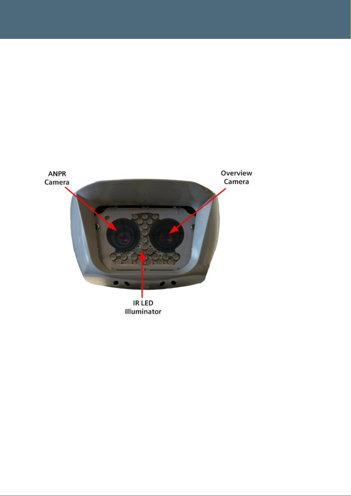
3.1. Product Overview
The Siemens Sicore II camera is a development from the successful Sicore 1 and provides the
next generation of image quality and performance.
Sicore II is highly flexible supporting many countries of the world delivering high quality
evidentially secure images. The camera utilises high resolution IR (ANPR) and colour or IR
(overview) sensors with a great depth of field enabling reading plates easily anywhere in the
view. ANPR functionality is provided in-camera resulting in a modular platform with a
comp act f or m fac tor.
Figure 1 – Sicore II – Front View
Sicore II Installation and Commissioning Guide
667/HB/52600/000 Issue 2 Unrestricted

Prod u c t Fea t ures Descrip t i on
17
3.2. Prod uc t Fea t u res
The main features of the Sicore II camera are:
Sleek sunshield design gives unique look to the camera
High performance quad core Intel Atom processor
High performance 2.3MPixel Camera(s)
Built-in powerful 850nm IR illuminator with full intensity/flash duration control
Multiple communications interfaces:
Gigabit Ethernet
3G/4G Ce llular (Optional)
WiFi (Optional)
RS232
RS422/RS485
Comprehensive isolated I/O interfaces
4 x Digital Inputs
4 x Digital Outputs
1 x Solid State Relay
1 x Power switch
Robust extruded Aluminium enclosure
Same pinout on Main connector as Sicore 1 allowing easy camera upgrade
Same mounting points as for Sicore 1 allowing easy camera upgrade
Factory sealed system - The camera is a factory sealed unit with no user serviceable parts
inside.
External equipment tamper on case disassembly and cable removal
Separately sealed SIM card enclosure for 3G/4G SIM when modem option ordered
A detailed technical specification can be found in Appendix A
Sicore II Installation and Commissioning Guide
667/HB/52600/000 Issue 2 Unrestricted

Prod u c t Fea t ures Descrip t i on
18
3.3. Product Variants and Options
The Sicore II camera is available in a wide number of variants and can be factory configured
with the following options:
Variant Description
1 Twin Camera – Mono/IR + Colour Overview
2 Twin Camera – Mono/IR + Mono/IR Overview
3 Single Camera – Mono/IR
Table 4 – Table of Base Variants
Option Description
1 3G/4G Modem module with antenna
2 WiFi module with antenna
3 8GB solid state storage module \
4 16GB solid state storage module |
5 32GB solid state storage module | Only one can be fitted
6 64GB solid state storage module |
7 128GB solid state storage module /
8 12.5mm Lens
9 16mm Lens
10 25mm Lens
11 35mm Lens
12 Grey sun shield
13 Yellow sun shield
Table 5 – Table of Options
Each Sicore II has two part numbers located on the rear of the camera.
The formal, orderable, part number is of the form S24745 –XXXXX-XXXX. This is the number
which must be quoted when ordering a camera.
To allow easy identification of the camera, there is also a ‘Human Readable’ part number
included on the rear of the camera. The structure of this i s describ ed in App endix C
Please contact Siemens to discuss orderable part numbers for the different
variants using contact details in Section 1.2
Sicore II Installation and Commissioning Guide
667/HB/52600/000 Issue 2 Unrestricted

Prod u c t Fea t ures Descrip t i on
19
4. Product Features Description
4.1. Serial Input / Output
The Sicore II camera is fitted with multiple isolated I/O ports that allow the unit to interface
with many type of external equipment such as:
• Serial trigger devices
• External modem
• Instation
4.1.1. Ethernet
This interface provides an auto detecting 10/100/1000 Ethernet interface and will generally
be used for fixed infrastructure instation communications. To achieve a Gigabit connection
the cable must be restricted to a maximum length of 100m.
4.1.2. RS232
This interface provides an isolated RS232 port with RTS & CTS flow control lines.
4.1.3. RS422/RS485
This interface provides an isolated 4 wire RS422 or 2 wire RS485 port. The port mode is set by
camera configuration.
4.2. Digital Input / Output
The Sicore II camera is fitted with multiple isolated I/O ports that allow the unit to interface
with many type of external equipment such as:
• External visible or IR flash lighting units
• Lane or carriageway vehicle detectors for external triggering
• Barrier control
The voltage between any of the isolated interface pins and system ground
must NOT exceed 50V DC
Apart from the four digital inputs which have their own isolated ground
return, all other isolated interfaces share the same isolated ground
4.2.1. Digital Inputs
Four isolated digital inputs are provided. These four inputs share one common isolated
ground return. This isolated ground is NOT connected to any other of the cameras ground
points. These inputs have the following specification:
• 12-24V DC input
• Input current limited to 7mA
• ELV level isolation
• Pro grammable po lar ity
Sicore II Installation and Commissioning Guide
667/HB/52600/000 Issue 2 Unrestricted

Prod u c t Fea t ures Descrip t i on
20
4.2.2. Digital Outputs
Four isolated digital outputs are provided. These outputs have the following specification:
• Protected Open Drain outputs *
• Maximum operating voltage: 50V DC
• Maximum operatin g cu rrent: 500mA
• ELV level isolation
• Pro grammable po lar ity
• Output 4 can be assigned as sync output function
* - Protection from, over voltage transients, over current and over temperature operation.
4.2.3. Power Switch
This interface provides a mechanism for switching an externally supplied voltage on or off.
This interface has the following specification:
• Protected solid state single pole switch
• Maximum operating voltage: 24V DC
• Maximum operatin g cu rrent: 500mA
• ELV level isolation
• Pro grammable po lar ity
4.2.4. Relay Output
This interface provides an isolated solid state changeover contact. This interface has the
following specification:
• Protected solid state single pole changeover contact
• Maximum operating voltage: 50V DC
• Maximum operating current: 100mA
• TR2523 compatible output
• Fuse protected (factory repair only)
• ELV level isolation
4.3. WiFi Interface
The WiFi interface is a factory fit option and allows the user to connect locally to the cameras
WiFi hotspot using a WiFi device such as a Laptop, Tablet or Smart Phone. The Sicore II
camera WiFi operates on 2.4GHz & 5GHz bands and has a useable range of 10-30m
depending on location and ambient noise floor.
For security purposes the WiFi hotspot is disabled by default, refer to the Sicore II Operating
Instructions Handbook (Ref para. 1.3)
Sicore II Installation and Commissioning Guide
667/HB/52600/000 Issue 2 Unrestricted

Prod u c t Fea t ures Descrip t i on
21
4.4. 3G/4G Interface
The 3G/4G modem interface is a factory fit option and allows the user to connect to the
camera over a 3G/4G link. The installation location should be checked for signal coverage for
the service provider selected.
Do not obstruct the top surface of the camera as the 3G/4G antenna is located under the sun
shield in this region.
A SIM must be fitted and the interface configured correctly for the modem to operate. See
section 5.6.6 for SIM installation. Refer to refer to the Sicore II Operating Instructions
Handbook (Ref para. 1.3) for modem configuration.
4.5. GPS / Clock System
The clock system uses the inbuilt GPS receiver. For this to work successfully the top of the
camera must have a good ‘view’ of the sky and not be obstructed in any way. A basic
configuration process and guidance on how to check the signal strength is included in
section 7.2. For a full description of this configuration refer to refer to the Sicore II Operating
Instructions Handbook (Ref para. 1.3)
Sicore II Installation and Commissioning Guide
667/HB/52600/000 Issue 2 Unrestricted

Prod u c t Fea t ures Descrip t i on
22
4.6. User Interface
The primary interface for user actions is a web based interface available locally on a network
via the Ethernet interface or via WiFi. This interface gives access to and control of all areas
necessary for day to day maintenance including:
• System Status and Configuration.
• Site Log
• Fault Table
• System Log
• System S tatus
• ANPR Live View
The following sections summarize the user interface tabs available. The User Interface is
described in detail in the Sicore II Operating Instructions Handbook Ref para 1.3.
Basic connection and logon information can be found in section 6.8.1.4 of this document.
4.6.1. System Status and Configuration
These pages allow the user to configure the system operation in detail as well as monitor
system functions.
4.6.2. Terminal
This provides a command line interface for entering various low level commands to the
camera. This interface should only be used by experienced installers under instruction from
Support Personnel from Siemens Plc.
4.6.3. Site Log
The Site Log records significant site events. System firmware update is automatically
recorded in the site log. It is also possible for the user to create text records, either with or
without a file attachment.
Attachments can be useful to record site details through diagrams, photographs, documents,
etc.
4.6.4. Fault Table
The Fault Table shows both Faults and Notifications that are currently active.
A fault is an abnormal condition which requires corrective action to be taken.
A notification provides information to the user but does not necessarily require any
immediate action.
Many faults will be automatically removed from the Fault Table when the condition which
caused the fault is removed. Some faults are latched and require manual clearing. A button is
displayed next to this latter type of fault which can be used to clear the fault. To clear the
fault, press the button and follow the instructions.
The ‘View History’ buttons show faults and notifications that have cleared automatically or
been manually cleared.
Sicore II Installation and Commissioning Guide
667/HB/52600/000 Issue 2 Unrestricted
Prod u c t Fea t ures Descrip t i on
23
4.6.5. System Log
Important events are recorded in the System Log. The source of the event with the date and
time at which the event occurred is recorded along with an indication of its severity:
Error
Notice
Warning
Information
With the default logging level configuration, only events with severity level of Notice and
Error are recorded in the System Log. Enabling the Warning and Information level of
logging is an advanced option not covered in this handbook (refer to Siemens Plc Support
Personnel).
4.6.6. System
The System tab shows the user the software build status of the camera. The camera is based
around a Linux operating system along with various software applications providing the
cameras’ functionality. The applications and their versions are displayed on this page
along with the ability to ‘Export Site Information’ which will generate a zip file containing
all of the available system logs.
At the bottom of the page there a re two buttons:
Reboot System – This allows the user to remotely reboot the system. (Note that this restarts
the camera Application Software but not the underlying Operation System)
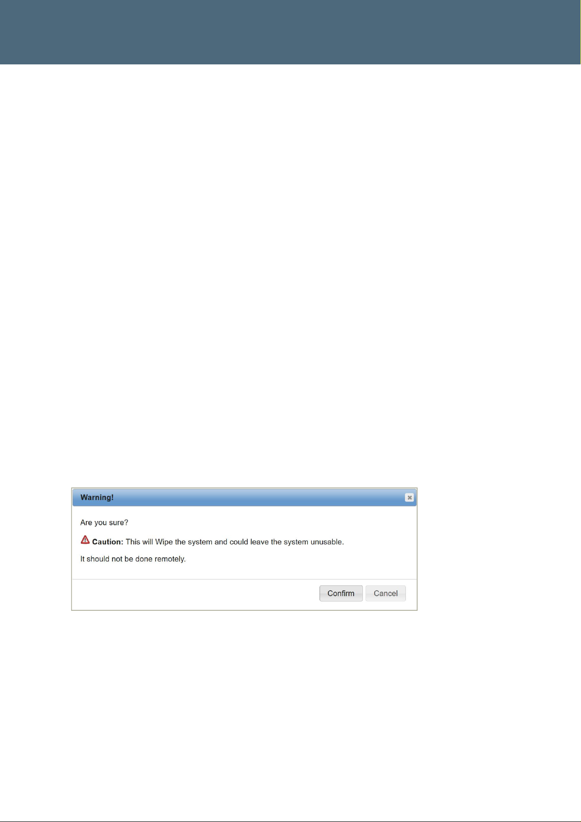
Wipe System – This provides a complete Factory Reset of the Camera configuration. The
system wipe should not be performed remotely because it will revert the camera to
factory default settings, including all network settings. The following warning is
displayed if this option is selected:
Figure 2 – Wipe System Warning
Note that, although Sicore II comes out of the factory with a fixed IP address (see section
1.7), use of the ‘Wipe System’ function will reset the network configuration to DHCP mode.
Sicore II Installation and Commissioning Guide
667/HB/52600/000 Issue 2 Unrestricted
Prod u c t Fea t ures Descrip t i on
24
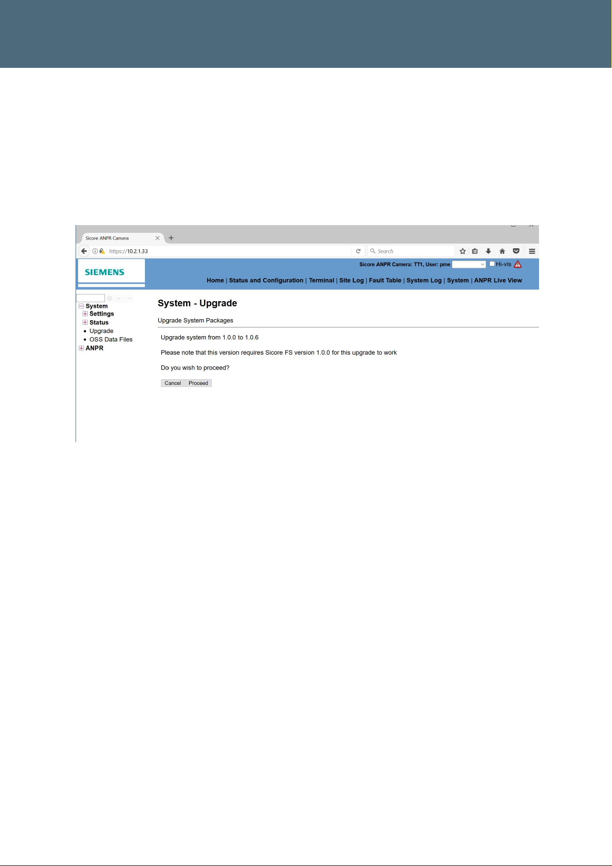
4.7. Firmware Upda te
The firmware within the unit is stored in non-removal devices. This firmware can be updated
by the user by navigating to Status & Configuration / System /Upgrade. Only Software
provided by Siemens Plc can be used here. Depending on the current and target version of
software for the camera there can be a minimum version requirement for the upgrade. This
will be confirmed when the upgrade file is applied.
Figure 3 – System Upgrade
Sicore II Installation and Commissioning Guide
667/HB/52600/000 Issue 2 Unrestricted
System Components
25
5. System Components
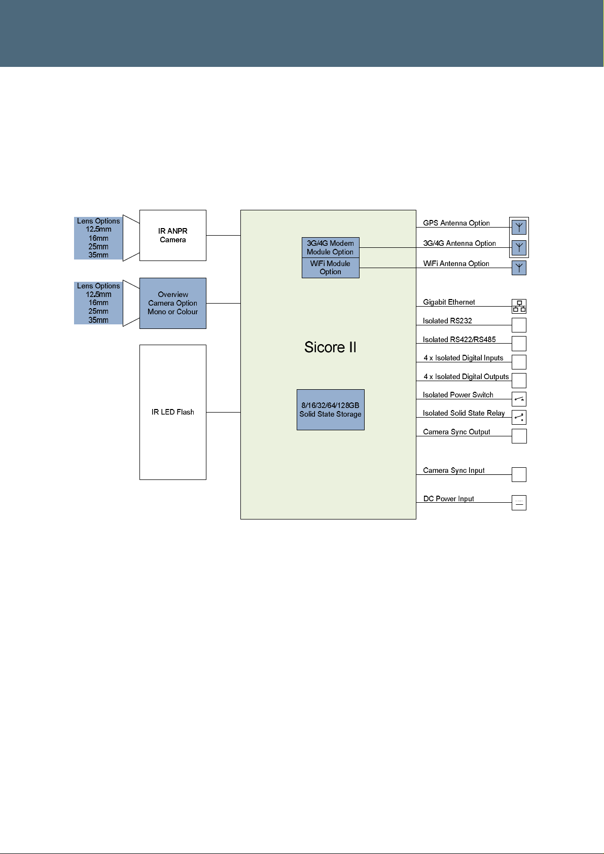
5.1. System Block Diagram
The Sicore II camera is a modular product that can be factory configured in a number of ways
to suit different applications. The main components and connections of the Sicore II Camera
are shown in Figure 4. The optional factory configuration parts are shown in blue.
Figure 4 – Sicore II System Overview
Sicore II Installation and Commissioning Guide
667/HB/52600/000 Issue 2 Unrestricted
System Components
26
5.2. Power Supply
The Sicore II Camera requires a 24V DC Supply within the limits as detailed in Table 6
The Sicore II camera consumes approximately 25W during operation.
Nominal Voltage Minimum Voltage Maximum Voltage
24V DC +10% -30%
16.8V at the camera 26.4V at the camera
Negative Earth
Table 6 – Power Supply Requirements
Siemens has tested and approved the following power supply modules:
Power Supply Model Manufacturer Rating Type Number of
Cameras
CLG-1 00-24 Meanwell 100W IP67 1
SDS150PS24B-LC XP Power 150W Open Frame 2
Table 7 – Siemens Approved Power Supplies
These power supply modules require de-rating for use at elevated temperatures. The number
of cameras stated is over the full temperature range.
To comply with EMC regulations it is necessary to use these power supplies
in combination with a Shaffner EMI Filter FN2020-10-06 or equivalent. The
Sicore II ‘Main cable’ screen must be securely terminated to the case of the
EMC filter / earth point of the power supply
5.3. Pole Mounted Power Supply Assembly
Siemens can supply a complete assembly designed to power a single Sicore II camera for
mounting in the base of a suitably sized pole, adjacent mains supply pillar or third party
cabinet.
The assembly comprises an IP65 rated 24V power supply, EMC filter, mains and DC
termination items with a cable clamp suitable for securing the Sicore main cable and
correctly terminating its screen.
Note that this assembly 667/1/46778/000 can only supply a single Sicore II camera.
Siemens can also supply a range of roadside cabinets for connection of multiple cameras or
inclusion of external communications equipment. Contact Siemens for information and
assistance using the contact details in Section 1.2.
Sicore II Installation and Commissioning Guide
667/HB/52600/000 Issue 2 Unrestricted
 Loading...