

Siemens SICLOCK TC 400 Operating Instructions Manual

SICLOCK
s
SICLOCK TC 400
Plant Central Clock
Operating Instructions 09/2007


09/2007
A2B00073596-01
SICLOCK® TC 400
Plant Central Clock
Operating Instructions
s
Preface, Table of contents
Safety Information
Description
Hardware Description
Operation Planning
Installation
Connecting
Configuration Tool
Parameterization
Parameterization and Operation on the Device
Parameter Table
Service and Maintenance
Messages
Technical Data
Dimension Drawing
Circuit Diagrams
Spare Parts / Accessories
Appendix
ESD Guidelines
List of Symbols
Glossary, Index
Siemens AG
I&S EDM
Frauenauracher Strasse 98
D-91056 Erlangen
GERMANY
© Siemens AG 2007
Technical data subject to change
Safety notices
This manual contains information that must be observed to ensure your personal safety and to prevent
property damage. The notices referring to your personal safety are highlighted in the manual by a safety
alert symbol, notices referring to property damage only, have no safety alert symbol. Depending on the
hazard level, warnings are displayed in descending order as follows:
In the event of a number of levels of danger prevailing simultaneously, the warning corresponding to the
highest level of danger is always used. A warning with a warning triangle indicating risk of physical injury
may also include a warning of the risk of damage to property.
Qualified personnel
The associated device/system may only be installed and used in conjunction with this documentation.
Only qualified personnel should be allowed to commission and operate the device/system. For the purpose of the safety information in this documentation, a “qualified person” is someone who is authorized to
energize, ground, and tag equipment, systems, and circuits in accordance with established safety procedures.
Intended use
Please note the following:
Registered Trademarks
All designations with the trademark symbol ® are registered trademarks of Siemens AG. Other designations in this documentation may be trademarks whose use by third parties for their own purposes can violate the rights of the owner.
Disclaimer of liability
We have checked that the contents of this publication agree with the hardware and software described
here. Nevertheless, we cannot assume responsibility for any deviations that may arise. The information
given in this publication is reviewed at regular intervals and any corrections that might be necessary are
made in the subsequent editions.
Danger
indicates that death or serious injury will result if proper precautions are not taken.
Warning
indicates that death or serious injury may result if proper precautions are not taken.
Caution
with a warning triangle indicates that minor personal injury can result if proper precautions are not taken.
Caution
without a warning triangle means that material damage can occur if the appropriate precautions are not
taken.
Notice
means an undesirable result or state can occur if the corresponding instruction is not followed.
Warning
This equipment is only allowed to be used for the applications described in the catalog and in the technical
description, and only in conjunction with non-Siemens equipment and components recommended by Siemens. Correct transport, storage, installation and assembly, as well as careful operation and maintenance,
are required to ensure that the product operates safely and without faults.

Preface-3© Siemens AG 2007 All Rights Reserved
SICLOCK
®
TC 400 Operating Instructions
Preface
This document is a compilation of the information required for the operation and
parameterization of the SICLOCK TC 400 plant central clock.
Scope
This manual is valid for the SICLOCK® TC 400 product with firmware version V1.0
and processor version V1.0 in conjunction with the SICLOCK TC 400 configuration tool as of Version 1.0.
Recycling and disposal
The SICLOCK TC 400 is environmentally friendly and is thus recyclable. To recycle and dispose of your old device in an environmentally friendly way, please contact a company certified to deal with electronic waste.
Hotline and Internet addresses
If you have any questions, please contact our hotline:
The latest information on SICLOCK products, product support and FAQs can be
found on the Internet.
Phone:
Fax:
E-mail:
Internet:
+49 (9131) 7-2 88 66
+49 (9131) 18-8 06 04
siclock@siemens.com
http://www.siemens.de/siclock (German)
http://www.siemens.com/siclock (international)

Preface
Preface-4
© Siemens AG 2007 All Rights Reserved
SICLOCK
®
TC 400 Operating Instructions

Contents-5© Siemens AG 2007 All Rights Reserved
SICLOCK
®
TC 400
Table of contents
Preface. . . . . . . . . . . . . . . . . . . . . . . . . . . . . . . . . . . . . . . . . . . . . . . . . . . . . . . Preface-3
Table of contents . . . . . . . . . . . . . . . . . . . . . . . . . . . . . . . . . . . . . . . . . . . . . . Contents-5
1 Safety Information . . . . . . . . . . . . . . . . . . . . . . . . . . . . . . . . . . . . . . . . . . . . . 1-9
2 Description . . . . . . . . . . . . . . . . . . . . . . . . . . . . . . . . . . . . . . . . . . . . . . . . . . . 2-11
2.1 Configuration of the SICLOCK TC 400 hardware . . . . . . . . . . . . . . . 2-12
2.2 External synchronization . . . . . . . . . . . . . . . . . . . . . . . . . . . . . . . . . . 2-13
2.3 Time receivers. . . . . . . . . . . . . . . . . . . . . . . . . . . . . . . . . . . . . . . . . . 2-14
2.3.1 Plant synchronization via Ethernet . . . . . . . . . . . . . . . . . . . . . . . . . . 2-14
2.3.2 Plant synchronization via point-to-point connection . . . . . . . . . . . . . 2-15
2.4 Time management . . . . . . . . . . . . . . . . . . . . . . . . . . . . . . . . . . . . . . 2-16
2.5 Commissioning . . . . . . . . . . . . . . . . . . . . . . . . . . . . . . . . . . . . . . . . . 2-16
2.6 Redundancy . . . . . . . . . . . . . . . . . . . . . . . . . . . . . . . . . . . . . . . . . . . 2-17
3 Hardware Description. . . . . . . . . . . . . . . . . . . . . . . . . . . . . . . . . . . . . . . . . . . 3-19
3.1 External design . . . . . . . . . . . . . . . . . . . . . . . . . . . . . . . . . . . . . . . . . 3-19
3.2 Connection elements. . . . . . . . . . . . . . . . . . . . . . . . . . . . . . . . . . . . . 3-20
3.3 Operator controls and displays . . . . . . . . . . . . . . . . . . . . . . . . . . . . . 3-21
3.4 Scope of delivery. . . . . . . . . . . . . . . . . . . . . . . . . . . . . . . . . . . . . . . . 3-23
4 Operation Planning. . . . . . . . . . . . . . . . . . . . . . . . . . . . . . . . . . . . . . . . . . . . . 4-25
4.1 Overview of operation planning. . . . . . . . . . . . . . . . . . . . . . . . . . . . . 4-25
4.2 Transport and storage conditions . . . . . . . . . . . . . . . . . . . . . . . . . . . 4-27
4.3 Unpacking and checking the delivery . . . . . . . . . . . . . . . . . . . . . . . . 4-28
4.4 Mounting position and fixing method. . . . . . . . . . . . . . . . . . . . . . . . . 4-29
4.4.1 Installation instructions . . . . . . . . . . . . . . . . . . . . . . . . . . . . . . . . . . . 4-29
4.4.2 Permitted mounting position . . . . . . . . . . . . . . . . . . . . . . . . . . . . . . . 4-30
4.4.3 Fixing method . . . . . . . . . . . . . . . . . . . . . . . . . . . . . . . . . . . . . . . . . . 4-30
5Installation. . . . . . . . . . . . . . . . . . . . . . . . . . . . . . . . . . . . . . . . . . . . . . . . . . . . 5-31
5.1 Installation overview . . . . . . . . . . . . . . . . . . . . . . . . . . . . . . . . . . . . . 5-31
6 Connecting . . . . . . . . . . . . . . . . . . . . . . . . . . . . . . . . . . . . . . . . . . . . . . . . . . . 6-33
6.1 Connecting overview . . . . . . . . . . . . . . . . . . . . . . . . . . . . . . . . . . . . . 6-33
6.2 Connecting the power supply . . . . . . . . . . . . . . . . . . . . . . . . . . . . . . 6-34

Table of contents
Contents-6
© Siemens AG 2007 All Rights Reserved
SICLOCK
®
TC 400
6.3 Connecting the external synchronization . . . . . . . . . . . . . . . . . . . . . 6-35
6.3.1 SICLOCK GPS1000 . . . . . . . . . . . . . . . . . . . . . . . . . . . . . . . . . . . . . 6-37
6.3.2 SICLOCK DCFRS industrial version . . . . . . . . . . . . . . . . . . . . . . . . . 6-38
6.3.3 SICLOCK GPSDEC . . . . . . . . . . . . . . . . . . . . . . . . . . . . . . . . . . . . . 6-39
6.3.4 Third-party systems. . . . . . . . . . . . . . . . . . . . . . . . . . . . . . . . . . . . . . 6-40
6.4 Connecting the time receivers. . . . . . . . . . . . . . . . . . . . . . . . . . . . . . 6-41
6.4.1 Point-to-point connections via OUTPUT 1 to 3 . . . . . . . . . . . . . . . . . 6-41
6.4.2 Redundant point-to-point connections. . . . . . . . . . . . . . . . . . . . . . . . 6-43
6.5 Connecting an alarm output and a warning output . . . . . . . . . . . . . . 6-44
7 Configuration Tool . . . . . . . . . . . . . . . . . . . . . . . . . . . . . . . . . . . . . . . . . . . . . 7-45
7.1 Menus . . . . . . . . . . . . . . . . . . . . . . . . . . . . . . . . . . . . . . . . . . . . . . . . 7-48
7.2 General functions . . . . . . . . . . . . . . . . . . . . . . . . . . . . . . . . . . . . . . . 7-50
7.2.1 Establish/disconnect online connection. . . . . . . . . . . . . . . . . . . . . . . 7-51
7.2.2 Authorization . . . . . . . . . . . . . . . . . . . . . . . . . . . . . . . . . . . . . . . . . . . 7-52
7.3 Parameters . . . . . . . . . . . . . . . . . . . . . . . . . . . . . . . . . . . . . . . . . . . . 7-53
7.3.1 Sorting the parameter table. . . . . . . . . . . . . . . . . . . . . . . . . . . . . . . . 7-57
7.3.2 Showing/hiding parameter table entries . . . . . . . . . . . . . . . . . . . . . . 7-57
7.3.3 Editing parameters . . . . . . . . . . . . . . . . . . . . . . . . . . . . . . . . . . . . . . 7-58
7.3.4 Reading parameters / writing parameters / resetting parameters to factory set-
tings. . . . . . . . . . . . . . . . . . . . . . . . . . . . . . . . . . . . . . . . . . . . . . . . . . 7-59
7.4 Archive . . . . . . . . . . . . . . . . . . . . . . . . . . . . . . . . . . . . . . . . . . . . . . . 7-60
7.4.1 Sorting the archive table . . . . . . . . . . . . . . . . . . . . . . . . . . . . . . . . . . 7-62
7.4.2 Filter . . . . . . . . . . . . . . . . . . . . . . . . . . . . . . . . . . . . . . . . . . . . . . . . . 7-63
7.5 Troubleshooting. . . . . . . . . . . . . . . . . . . . . . . . . . . . . . . . . . . . . . . . . 7-64
8 Parameterization and Operation on the Device. . . . . . . . . . . . . . . . . . . . . . 8-67
8.1 Operating display . . . . . . . . . . . . . . . . . . . . . . . . . . . . . . . . . . . . . . . 8-68
8.2 Operation and parameterization . . . . . . . . . . . . . . . . . . . . . . . . . . . . 8-70
8.2.1 Authorization (enter password) . . . . . . . . . . . . . . . . . . . . . . . . . . . . . 8-71
8.2.2 Parameter list . . . . . . . . . . . . . . . . . . . . . . . . . . . . . . . . . . . . . . . . . . 8-72
8.2.3 Editing dialog box . . . . . . . . . . . . . . . . . . . . . . . . . . . . . . . . . . . . . . . 8-73
9 Parameterization . . . . . . . . . . . . . . . . . . . . . . . . . . . . . . . . . . . . . . . . . . . . . . 9-75
9.1 Linking the external synchronization . . . . . . . . . . . . . . . . . . . . . . . . . 9-76
9.1.1 Radio clocks via terminals. . . . . . . . . . . . . . . . . . . . . . . . . . . . . . . . . 9-76
9.1.2 Operation as NTP client . . . . . . . . . . . . . . . . . . . . . . . . . . . . . . . . . . 9-77
9.1.3 Redundancy . . . . . . . . . . . . . . . . . . . . . . . . . . . . . . . . . . . . . . . . . . . 9-77
9.2 Linking the time receivers . . . . . . . . . . . . . . . . . . . . . . . . . . . . . . . . . 9-78
9.2.1 NTP server service . . . . . . . . . . . . . . . . . . . . . . . . . . . . . . . . . . . . . . 9-78
9.2.2 SIMATIC method. . . . . . . . . . . . . . . . . . . . . . . . . . . . . . . . . . . . . . . . 9-79
9.2.3 OUTPUT 1 to 3 via terminals . . . . . . . . . . . . . . . . . . . . . . . . . . . . . . 9-80
9.2.4 OUTPUT 1 and 2 redundant . . . . . . . . . . . . . . . . . . . . . . . . . . . . . . . 9-81
9.2.5 Output telegram (for OUTPUT 1 to 3) . . . . . . . . . . . . . . . . . . . . . . . . 9-82

Table of contents
Contents-7
© Siemens AG 2007 All Rights Reserved
SICLOCK
®
TC 400
9.3 General settings on the device . . . . . . . . . . . . . . . . . . . . . . . . . . . . . 9-83
9.3.1 Time management . . . . . . . . . . . . . . . . . . . . . . . . . . . . . . . . . . . . . . 9-83
9.3.2 Synchronization. . . . . . . . . . . . . . . . . . . . . . . . . . . . . . . . . . . . . . . . . 9-84
9.3.3 Display. . . . . . . . . . . . . . . . . . . . . . . . . . . . . . . . . . . . . . . . . . . . . . . . 9-85
9.3.4 System . . . . . . . . . . . . . . . . . . . . . . . . . . . . . . . . . . . . . . . . . . . . . . . 9-85
9.3.5 Temperature . . . . . . . . . . . . . . . . . . . . . . . . . . . . . . . . . . . . . . . . . . . 9-86
9.3.6 Battery . . . . . . . . . . . . . . . . . . . . . . . . . . . . . . . . . . . . . . . . . . . . . . . . 9-86
10 Parameter Table . . . . . . . . . . . . . . . . . . . . . . . . . . . . . . . . . . . . . . . . . . . . . . . 10-87
11 Service and Maintenance. . . . . . . . . . . . . . . . . . . . . . . . . . . . . . . . . . . . . . . . 11-99
11.1 Battery . . . . . . . . . . . . . . . . . . . . . . . . . . . . . . . . . . . . . . . . . . . . . . . . 11-99
11.2 Restoring the factory settings . . . . . . . . . . . . . . . . . . . . . . . . . . . . . . 11-99
11.3 Software update . . . . . . . . . . . . . . . . . . . . . . . . . . . . . . . . . . . . . . . . 11-100
12 Messages . . . . . . . . . . . . . . . . . . . . . . . . . . . . . . . . . . . . . . . . . . . . . . . . . . . . 12-101
13 Technical Data . . . . . . . . . . . . . . . . . . . . . . . . . . . . . . . . . . . . . . . . . . . . . . . . 13-105
14 Dimension Drawing . . . . . . . . . . . . . . . . . . . . . . . . . . . . . . . . . . . . . . . . . . . . 14-109
15 Circuit Diagrams. . . . . . . . . . . . . . . . . . . . . . . . . . . . . . . . . . . . . . . . . . . . . . . 15-111
15.1 Terminal assignment . . . . . . . . . . . . . . . . . . . . . . . . . . . . . . . . . . . . . 15-111
16 Spare Parts / Accessories . . . . . . . . . . . . . . . . . . . . . . . . . . . . . . . . . . . . . . . 16-113
A Appendix . . . . . . . . . . . . . . . . . . . . . . . . . . . . . . . . . . . . . . . . . . . . . . . . . . . . . A-115
A.1 Directives and declarations . . . . . . . . . . . . . . . . . . . . . . . . . . . . . . . . A-115
A.2 Certificates and approvals. . . . . . . . . . . . . . . . . . . . . . . . . . . . . . . . . A-116
B ESD Guidelines. . . . . . . . . . . . . . . . . . . . . . . . . . . . . . . . . . . . . . . . . . . . . . . . B-117
B.1 Electrostatic sensitive devices. . . . . . . . . . . . . . . . . . . . . . . . . . . . . . B-117
B.2 Electrostatic charging of persons . . . . . . . . . . . . . . . . . . . . . . . . . . . B-118
B.3 Basic measures to protect against the
discharge of static electricity . . . . . . . . . . . . . . . . . . . . . . . . . . . . . . B-119
C List of Symbols . . . . . . . . . . . . . . . . . . . . . . . . . . . . . . . . . . . . . . . . . . . . . . . . C-121
D Glossary . . . . . . . . . . . . . . . . . . . . . . . . . . . . . . . . . . . . . . . . . . . . . . . . . . . . . D-123
Index . . . . . . . . . . . . . . . . . . . . . . . . . . . . . . . . . . . . . . . . . . . . . . . . . . . . . . . . Index-129

Table of contents
Contents-8
© Siemens AG 2007 All Rights Reserved
SICLOCK
®
TC 400
1-9© Siemens AG 2007 All Rights Reserved
SICLOCK
®
TC 400
Safety Information 1
If you have questions about the validity of the installation in the planned environment, please contact your service representative.
Repairs
Only authorized personnel are permitted to repair the device.
System expansions
Only install system expansions intended for this device. If you install other
upgrades, you may damage the system or violate the safety requirements and
regulations for radio frequency interference suppression.
Contact your technical support team or where you purchased your device to find
out which system expansion devices may safely be installed.
Caution
Please observe the safety instructions on the back of the cover sheet of this documentation. You should not make any expansions to your device unless you have
read the relevant safety instructions.
Warning
Unauthorized opening and improper repairs can cause considerable damage to
property or danger for the user.
Caution
If you install or exchange system expansions and damage your device, the warranty becomes void.
Safety Information
1-10
© Siemens AG 2007 All Rights Reserved
SICLOCK
®
TC 400
Battery
This device is equipped with a Lithium battery. Batteries may only be replaced by
qualified personnel. See also Battery (Section 11.1).
ESD guidelines
Modules containing electrostatic sensitive devices (ESDs) can be identified by the
following label:
Strictly follow the guidelines mentioned below when handling modules which are sensitive
to ESD:
• Always discharge your body's static electricity before handling modules which
are sensitive to ESD (for example,
by touching a grounded object).
• All devices and tools must be free of static charge.
• Always pull the mains connector and disconnect the battery before you install
or remove modules which are sensitive to ESD.
• Handle modules fitted with ESDs by their edges only.
• Do not touch any connector pins.
Caution
There is the risk of an explosion if the battery is not replaced as directed. Replace
only with the same type or with an equivalent type recommended by the manufacturer. Dispose of used batteries in accordance with local regulations.
Warning
Risk of explosion and release of harmful substances!
Therefore, do not throw Lithium batteries into an open fire, do not solder or open
the cell body, do not short-circuit or reverse polarity, do not heat up above 100°
C, dispose as regulated and protected against direct exposure to sunlight, humidity and condensation.

2-11© Siemens AG 2007 All Rights Reserved
SICLOCK
®
TC 400
Description 2
Modern automation systems consist of a variety of computers, controllers and
systems that exchange data with one another. For real-time operation of such
plants, it is essential that the times of all components are synchronous. This
applies especially for error tracing, when event messages receive a time stamp
and when cause and effect have to be identified through a reliable chronological
sequence.
As plant central clock, SICLOCK TC 400 supplies the various plant components
with the exact and reliable time, which is obtained from one or more external synchronizations with an official or legal time, usually GPS or DCF77 radio clocks.
The time is distributed via Ethernet, and also via point-to-point outputs.
Note
Use only one device as plant central clock to supply the time to all components
throughout the plant.
Exception: redundant operation of the plant central clock.
Description
2-12
© Siemens AG 2007 All Rights Reserved
SICLOCK
®
TC 400
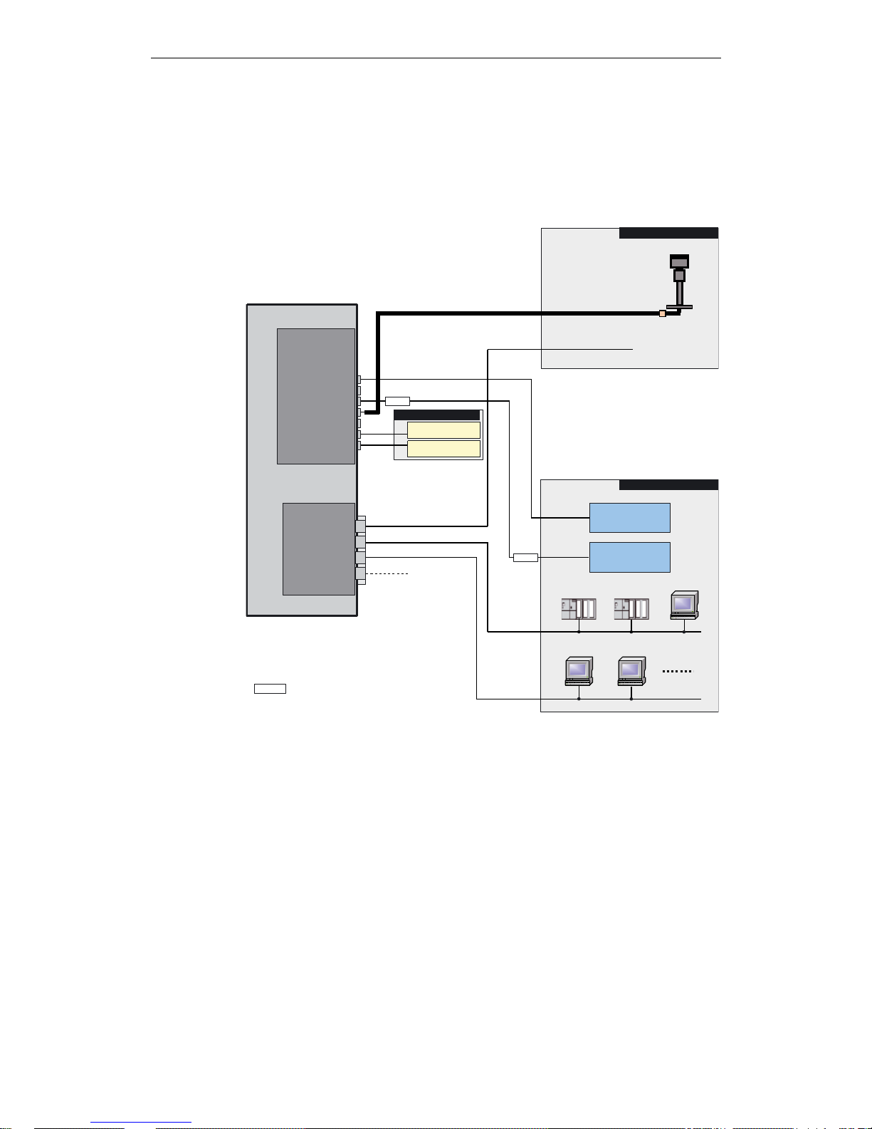
2.1 Configuration of the SICLOCK TC 400 hardware
The following figure shows a connection example of the SICLOCK TC 400 to a
SICLOCK GPS1000 as radio clock and an NTP server as an additional external
synchronization.
Figure 2-1 Application example
(WKHUQHW3RUWV
6,&/2&.7&
;
287387
287387
5$',2&/2&.
$/$50
:$51,1*
287387
5$',2&/2&.
6,&/2&.*36
1736HUYHU
Arbeitsstation
6
6
3&
Arbeitsstation
3&
Arbeitsstation
3&
3&21
3&21
3&21
6,&/2&.3&21
HOHFWULFDORSWLFDOSXOVHFRQYHUWHURSWLRQDO
([WHUQDOV\QFKURQL]DWLRQV
([WHUQDOV\QFKURQL]DWLRQ
7LPHUHFHLYHUV
$ODUPZDUQLQJ
,QVWUXPHQWDWLRQ
DQGFRQWURO
,QVWUXPHQWDWLRQ
DQGFRQWURO
5HFHLYHUVYLD
FXUUHQWVLJQDO
YROWDJHVLJQDO
5HFHLYHUVYLD
3&21
([WHUQDOV\QFKURQL]DWLRQ

Description
2-13
© Siemens AG 2007 All Rights Reserved
SICLOCK
®
TC 400
2.2 External synchronization
SICLOCK TC 400 can be matched to the local official time or GMT via external
synchronization in order to automate or restrict manual actions, such as daylight
saving time switchovers and leap seconds, to a minimum.
External synchronizations can be GPS or DCF77 radio clocks, servers (e.g. time
signal from an NTP server), further SICLOCK TC 400 devices or other signal
sources. They are connected to RADIO CLOCK 1 or RADIO CLOCK 2 or to one
of the four Ethernet ports on the device.
NTP servers are supported as external synchronization on the Ethernet ports.
Possible radio clocks to RADIO CLOCK 1 and RADIO CLOCK 2:
• SICLOCK GPS1000
• SICLOCK GPSDEC
• SICLOCK DCFRS
Third-party products can be connected via TTY (passive). The following protocols
are supported:
• Demodulated DCF77
• Serial:
− Meinberg compatible (including time zones)
− Meinberg compatible (not including time zones)
− NMEA (0183/ZDA)
Further information
Linking the external synchronization (Section 9.1)

Description
2-14
© Siemens AG 2007 All Rights Reserved
SICLOCK
®
TC 400
2.3 Time receivers
The time receivers of the plant can be connected via Ethernet or directly on the
device via point-to-point connections.
2.3.1 Plant synchronization via Ethernet
Physical access
There are four Ethernet interfaces available as physical access to the network
with the following specification:
• 100Base TX via RJ-45 socket
Protocols
The following protocols have been implemented:
• NTP server according to RFC2030
− Any/unicast mode
− Multicast mode
− Multicast mode with local time
• Time synchronization with the SIMATIC method
− PCS7-compatible mode
− S5-compatible mode
The time telegrams can be sent individually at each Ethernet port every second, every 10 seconds or every minute.

Description
2-15
© Siemens AG 2007 All Rights Reserved
SICLOCK
®
TC 400
2.3.2 Plant synchronization via point-to-point connection
Non-networked plant equipment is synchronized via OUTPUTs 1 to 3 (point-topoint connections). They can be parameterized independently.
OUTPUTs 1 and 2
• Current signal: 20 mA active, floating
or
• Voltage signal: 24 V, floating
OUTPUT 3
RS422, floating
Output signal
• DCF77 with local time, invertible
• DCF77 with UTC, invertible
• Pulse per second, invertible
• Pulse per minute, invertible
• Serial telegram (parameterizable output telegram, see below)
Output telegram (setting applies to all three outputs)
• Meinberg compatible (including time zones)
• Meinberg compatible (not including time zones)
• NMEA (0183/ZDA)

Description
2-16
© Siemens AG 2007 All Rights Reserved
SICLOCK
®
TC 400
2.4 Time management
Various functions are available in SICLOCK TC 400 in order to generate the time
valid for the plant from the external synchronization. This includes setting options
for time zones as well as the parameterizable daylight saving time.
Time assurance through protected synchronization
If a discontinuity of more than 5 s occurs in the external synchronization, the protected synchronization is activated and, for safety reasons, the synchronization
not performed.
Time assurance through microstepping mode
A time difference between the external synchronization and the device, which can
occur through a temporary radio failure or switchover to a substitute synchronization, is automatically cleared unnoticeably in microstepping mode for the plant
operation. There is no inconsistency in the time.
Further information and parameterization options for protected synchronization
and the microstepping mode are described in Section Synchronization
(Section 9.3.2).
2.5 Commissioning
The commissioning can be divided into the following steps:
1. Installation (Section 5)
2. Connecting (Section 6)
3. Assigning IP address on the device
Parameterization and Operation on the Device (Section 8)
4. Parameterization (Section 9)
With a few exceptions, the settings are made with the configuration tool, see
Configuration Tool (Section 7).
Note
Only parameterize the plant time at one location within the synchronization hierarchy, ideally at the plant central clock.

Description
2-17
© Siemens AG 2007 All Rights Reserved
SICLOCK
®
TC 400
2.6 Redundancy
Redundant external synchronization
Up to two radio clocks and up to four time servers can be operated on the
SICLOCK TC 400 for the external synchronization.
The priorities of the external synchronizations and therefore the redundancy
behavior can be set via parameters, see Redundancy (Section 9.1.3).
Redundant SICLOCK TC 400 plant central clock
A SICLOCK TC 400 can be operated via various ports on a redundant network
and several SICLOCK TC 400 can be operated as servers on one network.
For further information, refer to Chapters Configuration Tool (Section 7) and
Parameter Table (Section 10).
Redundant control of time receivers (output redundancy)
At least two SICLOCK TC 400 are used for an output redundancy. With the appropriate parameterization, OUTPUTs 1 and 2 of the two devices can each be connected redundantly with the other.
For further information, refer to Sections Redundant point-to-point connec-
tions (Section 6.4.2) and OUTPUT 1 and 2 redundant (Section 9.2.4).

Description
2-18
© Siemens AG 2007 All Rights Reserved
SICLOCK
®
TC 400
3-19© Siemens AG 2007 All Rights Reserved
SICLOCK
®
TC 400
Hardware Description 3
This chapter describes the hardware design with connections, the operator controls and displays.
3.1 External design
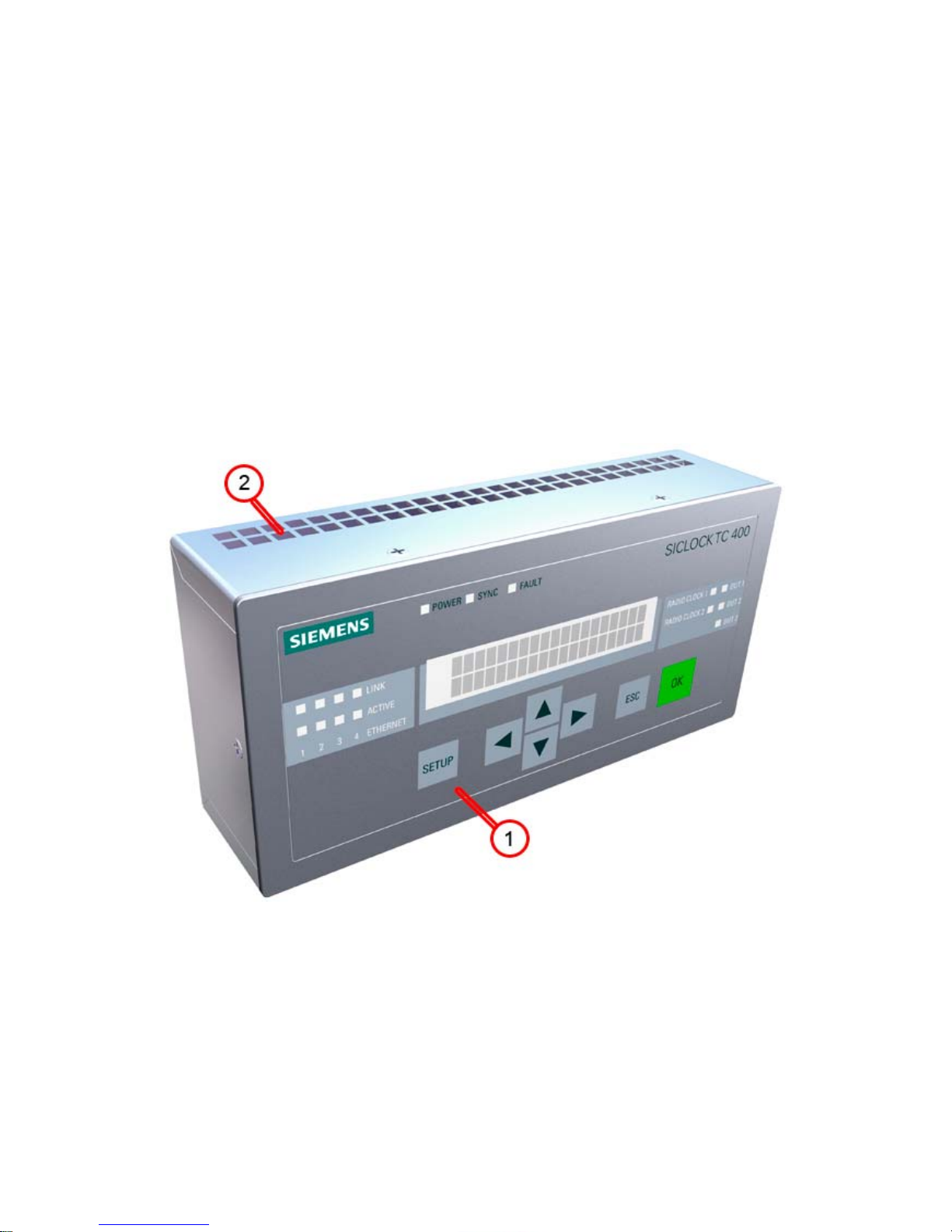
The following figures show the displays and operator controls as well as the connections of the SICLOCK TC 400.
Figure 3-1 SICLOCK TC 400 - perspective view with front panel and ventilation grille
(1) Panel with operator controls and displays
(2) Ventilation grille

Hardware Description
3-20
© Siemens AG 2007 All Rights Reserved
SICLOCK
®
TC 400
3.2 Connection elements
The following figure shows the connections of the SICLOCK TC 400.
Figure 3-2 SICLOCK TC 400 - arrangement of the connections
(1) Terminal X1 - 24 V power supply
(2) Terminal X2 - connecting terminal for radio clocks, outputs and alarm
See also Terminal assignment (Section 15.1).
(3) Four Ethernet ports
Hardware Description
3-21
© Siemens AG 2007 All Rights Reserved
SICLOCK
®
TC 400
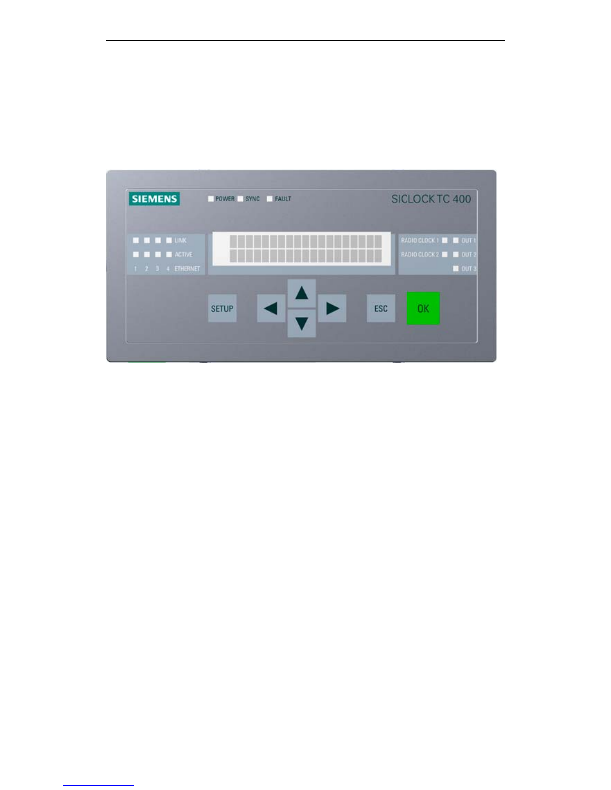
3.3 Operator controls and displays
The front panel shows the current mode in the display and with LEDs. The device
can be operated directly via the keypad. A Web-based configuration tool is available for a wide range of configuration options, see Configuration Tool
(Section 7).
Figure 3-3 SICLOCK TC 400 front view

Hardware Description
3-22
© Siemens AG 2007 All Rights Reserved
SICLOCK
®
TC 400
For further information, see Parameterization and Operation on the Device
(Section 8)
.
Table 3-1 Meaning of the displays and operator controls
Name Color (LED) Meaning
Displays
POWER Green Ready to run
SYNC Green SICLOCK TC 400 has been externally synchronized
FAULT Red Alarm
The associated message text is shown in the display.
Flashing red Warning
The associated message text is shown in the display.
LINK (Port 1-4) Yellow Physical connection has been established, possible to send
and receive
ACTIVE (Port 1-4) Green Display of the data traffic for the respective port
RADIO CLOCK 1 Yellow Receive signal of radio clock 1
RADIO CLOCK 2 Yellow Receive signal of radio clock 2
OUT 1 Green Output 1
Output signal at the terminal
OUT 2 Green Output 2
Output signal at the terminal
OUT 3 Green Output 3
Output signal at the terminal
Display Display of time, date and synchronization or message text
when an error occurs
Operator controls
SETUP Call of the password input or parameter list
↑ ↓ ← →
Navigation in the menus
ESC • Cancellation of an entry and return to the call menu.
• Switchover from an information message or warning to the
mode display
• Change to operator control for a limited period when a per-
sistent message is pending.
OK Accepting of entries and acknowledging of messages

Hardware Description
3-23
© Siemens AG 2007 All Rights Reserved
SICLOCK
®
TC 400
3.4 Scope of delivery
Table 3-2 Scope of delivery of the individual device versions
2XV9450-2AR01
SICLOCK TC 400 single device with terminal strips connected at X1 and X2
Operating instructions on CD
2XV9450-2AR10 (SICLOCK TC 400 standard package)
SICLOCK TC 400 single device with terminal strips connected at X1 and X2
Operating instructions on CD
SICLOCK GPS1000 radio clock complete with mounting frame and lightning protection
2XV9450-2AR20 (SICLOCK TC 400 DCF77 package)
SICLOCK TC 400 single device with terminal strips connected at X1 and X2
Operating instructions on CD
SICLOCK DCFRS radio clock industrial version complete with mounting frame

Hardware Description
3-24
© Siemens AG 2007 All Rights Reserved
SICLOCK
®
TC 400

4-25© Siemens AG 2007 All Rights Reserved
SICLOCK
®
TC 400
Operation Planning 4
4.1 Overview of operation planning
SICLOCK TC 400 has been designed for weather-protected, stationary operation
in an industrial environment.
The operating conditions surpass the requirements according to DIN IEC 607213-3:
• Class 3M3 (mechanical requirements)
• Class 3K3 (climatic requirements)
General information about operation
Avoid extreme ambient conditions. Protect your device against dust, moisture and
heat. For further information, see Chapter Technical Data (Section 13).
Do not place the device in direct sunlight.
Caution
The device is approved for operation in closed rooms only. The guarantee is void
if this stipulation is ignored.
Condensation
When transporting the device at low temperatures, ensure that no moisture forms
on or in the device. This also applies if the device is subjected to extreme changes
in temperature.
Commissioning
Allow the device to slowly adjust to room temperature before commissioning. Do
not place the device near heat radiation. With large differences in temperature,
harmful condensation can be avoided by leaving the device in the transport packaging.
If condensation occurs, wait at least about 12 hours before you switch on the
device (for 20° C temperature difference). The waiting period is extended accordingly for greater temperature differences.

Operation Planning
4-26
© Siemens AG 2007 All Rights Reserved
SICLOCK
®
TC 400
Use in residential areas and operation in the public network
If you operate the SICLOCK TC 400 in residential areas or in the public network,
you must ensure that it complies with the limit class B according to EN 55022 with
regard to the emission of radio interference.
The following measures are recommended to ensure the interference complies
with limit class B:
• Installation of the SICLOCK TC 400 in grounded control cabinets / control
boxes
• Use of filters in electrical supply lines
Use with additional measures
Applications where the use of the SICLOCK TC 400 or similar device requires
additional measures:
• Locations with a high percentage of ionizing radiation
• Locations with extreme operating conditions, such as
− dust accumulation
− corrosive vapors or gases
− strong electric or magnetic fields
− damp and wet rooms
− strong oscillations, shocks, vibrations
− strong radiant heat
• In systems, which require special monitoring, such as
− elevators
− electrical plants in potentially hazardous areas
An additional measure, for example, would be to install the SICLOCK TC 400 in
a cabinet or housing.
Note
This is a a class A device. The device may cause RF interference in residential
areas or in the public network. In this case, the operator company may be held
liable for taking appropriate measures.

Operation Planning
4-27
© Siemens AG 2007 All Rights Reserved
SICLOCK
®
TC 400
4.2 Transport and storage conditions
Although the device is of rugged design, its internal components are sensitive to
severe vibrations or shock. You must therefore protect the device against severe
mechanical loads.
You should always use the original packaging for shipping and transporting the
device.
Unpack the device at its final destination.
Do not transport the device when it is mounted.
Observe the notes about temporary storage in Chapter Service and Mainte-
nance under Battery (Section 11.1).
The following information applies to modules transported and stored in the original packaging.
The climatic environmental conditions correspond to IEC 60721-3-2, Class 2K4
for transport
The mechanical environmental conditions correspond to IEC 60721-3-2, Class
2M2 for transport
Caution
Risk of damage to the device!
If you are transporting the device in cold weather with large fluctuations in temperature, care must be taken to ensure that no moisture forms on or in the device
(condensation).
If condensation has developed, wait at least 12 hours before you switch on the
device.
Caution
Observe these conditions each time the device is transported, otherwise the guarantee is void.
Table 4-1 Transport and storage conditions
Type of condition Permissible range
Free fall (in transport packaging)
<= 1 m
Temperature
-40° C to +70° C
Atmospheric pressure
1080 to 660 hPa (corresponds to an altitude
of -1000 to 3500 m)
Maximum temperature change
20° C/h
Relative humidity
10 to 95% (at 25° C without condensation)

Operation Planning
4-28
© Siemens AG 2007 All Rights Reserved
SICLOCK
®
TC 400
4.3 Unpacking and checking the delivery
The device has been completely assembled, tested and packed in the factory and
has no internal transport locks.
If there are large temperature differences between the transport medium and the
location where the device is unpacked, it is recommended that the device be left
in the transport packaging in order to avoid harmful condensation.
Procedure
• Please check the packaging material for transport damage upon delivery.
• If any transport damage is present at the time of delivery, lodge a complaint at
the shipping company in charge. Have the shipper confirm the transport damage immediately.
• Unpack the device.
• Keep the packaging material in case you have to transport the device again.
• Please keep the enclosed documentation in a safe place. You will need the
documentation when you commission the device for the first time.
• Check the package contents for completeness and any visible transport dam-
age. Check for completeness using the enclosed "Contents of Delivery" list.
• Notify the delivery service in charge immediately if the package contents are
incomplete or damaged.
Caution
The packaging protects the device during transport and storage. Transport the
device only in the original packaging!
Warning
Make sure that a damaged device is not installed and commissioned unintentionally.
 Loading...