

Siemens SICAM TM Installation Manual

SICAM TM
________________________________
________________________________
___________
Preface, Table of Contents
___________________________________________________________________________
Architecture 1
___________________________________________________________________________
Components 2
___________________________________________________________________________
Installation
Assembly 3
___________________________________________________________________________
Wiring Communi cation
___________________________________________________________________________
Wiring for the Reception of Time Signals
___________________________________________________________________________
4
5
Wiring Watchdog and Error 6
___________________________________________________________________________
Power Supply 7
___________________________________________________________________________
Wiring Peripheral Elements 8
___________________________________________________________________________
Wiring Process Peripherals 9
___________________________________________________________________________
Shielding / Protective Earthing 10
___________________________________________________________________________
DC6-015-2.04
Labelling 11
___________________________________________________________________________
Parameter Setting Preparation 12
___________________________________________________________________________
Recommended and tested purchased
products
___________________________________________________________________________
A
Licensing Agreement B
___________________________________________________________________________
Literature
___________________________________________________________________________

Hint
Disclaimer of Liability
for conformity with the hardware and software described, we cannot
included in the next releases. Any suggestions for improvement are
welcome.
Copyright
Please observe Notes and Warnings for your own safety in the Preface.
Although we have carefully checked the contents of this publication
guarantee complete conformity since errors cannot be excluded.
The information provided in this manual is checked at regular
intervals and any corrections that might become necessary are
Subject to change without prior notice
Document Label:
SICRTUs-HBTMACPINSTALL-ENG-V2.04
Release date:
2014.10.17
Copyright © Siemens AG 2014
The reproduction, transmission or use of this document or its
contents is not permitted without express written authority.
Offenders will be liable for damages. All rights, including rights
created by patent grant or registration of a utility model or design,
are reserved.
Siemens AG Bestell nr. : D C6-015-2 .0 4

Preface
This document is applicable to the following product:
· SICAM TM
Purpose of this manual
This handbook describes how the hardware of a SICAM TM system is to be installed and
which preparations ar e to be made for th e subsequent parameter settings.
Thereby the following points are described step-by-step:
· Conception of the architecture
· Installation of the hardware
· Label
· Wiring
· Parameter Setting Preparation
Target Group
This handbook is intended for persons who are entrusted with the design and installation of
SICAM TM systems.
Conventions used
· Outputs visible on the screen are descri bed in thi s font.
· Inputs via keyboard or mouse keys and visible on the screen are also de sc ri be d in
this font .
· Cro ss ref eren ces to ot her cha pter s or manual s are rep res ent ed in ita lics , suc h as e.g.
Common Functions System and Basic System Elements, section "Information Objects".
SICAM TM, Installation 3
DC6-015-2.04, Edition 10.2014
Notes on Safety
This manual does not constitute a complete catalog of all safety measures required for
operating the equipment (module, device) in question because special operating conditions
might require additional measures. However, it does contain notes that must be adhered to for
your own personal safety and to avoid damage to property. These notes are highlighted with a
warning triangle and different keywords indicating different degrees of danger.
Danger
means that death, serious bodily injury or c onsiderable prop er ty damage will occur, if the appropriate
precaut ionary meas ures are n ot carried out.
Warning
means that death, serious bodily injury or c onsiderable prop er ty damage can occur, if the appropriate
precaut ionary meas ures are n ot carried out.
Caution
means that minor bodily injury or property damage c ould occur, if the ap propriate precautionary measures
are not c arr ied out.
Hint
is import ant information about t he product, the handli ng of the product or the respective part of the
documentation, to which special attention is to be given.
Qualified Personnel
Commis sioning and operat ion of the equipment (module, device) describ ed i n t his manual must be
perfor med by qu alified personnel only. As used in the safety notes contained in this manual, qualified
personn el are thos e p ersons wh o are authorized to commission, release, ground, and tag d evices,
systems, and el ectrical circuits in accordance with s afety standards.
Use as Pres cr ib ed
The equipment (device, module) must not be used for any other purposes than those described in the
Catalog and the T echnical Description. If it is used together with third-party devices and components ,
these mus t b e r ec ommend ed or approved b y Siemens.
Correct and saf e operation of the product r equires adequat e transportation, storage, installation, and
mounti ng as well as appropriate use and m aintenance.
During op eration of electrical equipm ent, it is unavoidable that certain parts of this equip ment will c arry
dangerous volt ages. Sever e injury or damage to property can occur if the appropriat e measures are not
taken:
· B efore making any conn ections at all, ground the equipment at the PE terminal.
· Hazardous volt ages can be present on all switching componen ts connected to the power suppl y.
· Even after the supply voltage has been disconnec ted, hazard ous voltag es can still be present in the
equipment (capacitor storage).
· Equipment with current transf ormer circuits must not be op erated while open.
· The limit values indicated in the manual or the operating instructions must not be exceeded; that also
applies to testing and commissioning.
4 SICAM TM, Installation
Edition 10.2014, DC6-01 5-2.04

Table of Contents
1. Architecture ................................................................................................................... 9
1.1. Mechan ical Design ......................................................................................... 10
1.2. Configu rations (Examples ).............................................................................. 11
1.2.1. 2 Periphera l E le men ts SIC AM TM, electr ically conne ct e d ......................... 11
1.2.2. 16 Periphe ral Elemen ts S IC AM TM, electrically con n e cted ....................... 12
1.2.3. 16 Periphe ra l Ele men ts SIC AM T M, optically conne cte d ........................... 13
1.2.4. 16 Peripheral Elements SICAM TM, electrically and optically connected ... 14
2. Components ................................................................................................................ 15
2.1. Maste r Contro l Modules .................................................................................. 16
2.2. Serial Interface Modules ................................................................................. 17
2.2.1. Serial Interface Proce sso r (SIP) ................................................................. 17
2.2.2. Netw ork Interface Proce sso r (NIP) ............................................................. 17
2.2.3. Field Bus Inter face Proce s s or (FIP) ........................................................... 18
2.3. Bus Interface Module ...................................................................................... 19
2.4. Powe r Supplies .............................................................................................. 19
2.5. Periphe ral Modules ......................................................................................... 20
3. Assembly ..................................................................................................................... 25
3.1. Necess ary Material ......................................................................................... 26
3.2. How an d wh e re ca n Installation ta ke place? ................................................... 27
3.2.1. Installat ion Location ................................................................................... 27
3.2.2. Installat ion Position .................................................................................... 27
3.2.3. Space Requirement ................................................................................... 28
3.2.4. Environ mental Condition s .......................................................................... 29
3.3. Installat ion of TS35 Rail (DIN Rail) .................................................................. 30
3.4. Installat ion of Cable Duct ................................................................................ 31
3.5. Installat ion o f Mas ter Con tro l Ele ment ............................................................. 32
3.5.1. Remova l/Sh ifting of the Master Contro l Ele ment ........................................ 3 3
3.5.2. Securing Mas ter Contro l Ele ment agains t Slipp ing ..................................... 34
3.6. Installat ion o f Bus Inte r fa ce Mod ules .............................................................. 35
3.6.1. Optical Ax Bus ........................................................................................... 3 5
3.6.1.1. Removin g/Sh ifting the Op tica l Bus Inter face Modu le ............................. 36
3.6.2. Electrica l Ax Bus ....................................................................................... 3 6
3.7. Installing TM Modules ..................................................................................... 37
3.7.1. Design an d Ele men ts o f a Module ............................................................. 37
3.7.2. Handling .................................................................................................... 38
3.7.3. Connection ................................................................................................ 39
3.7.4. Order ......................................................................................................... 40
SICAM TM, Installation 5
DC6-015-2.04, Edition 10.2014

Table of Contents
4. Wiring Communic ation ............................................................................................... 4 1
4.1. Introdu ction .................................................................................................... 42
4.2. Configuring Master Control Element with Serial Interface Modules (SIM) ........ 43
4.2.1. Opening the Hous ing ................................................................................. 4 4
4.2.2. Removin g/F itt ing the SIM Retaine r ............................................................ 45
4.2.3. Installing Pat ch Plugs and SIMs ................................................................. 4 6
4.2.4. Fixing the SIMs.......................................................................................... 47
4.2.5. Configu ration Notes ................................................................................... 4 9
4.3. Wiring Commu nica tion ................................................................................... 5 0
4.3.1. Serial Commun icat ion ............................................................................... 5 1
4.3.1.1. Point-to-Point Traffic / Multi-Point Traffic via Dedicated Line Modem and
WT Chann el Modem ............................................................................. 5 1
4.3.1.2. Multi-Po int Tra ffic via Glas s Fibre Optic and Star Conn ectio n ................ 52
4.3.1.3. Analog Dial-up Traffic ........................................................................... 5 3
4.3.1.3.1. Wester mo TD36 Modem with externa l Pow er Supp ly ....................... 54
4.3.1.4. Dial-up tra ffic analog /GSM /ISD N .......................................................... 55
4.3.1.5. GSM Dial-up Traffic .............................................................................. 56
4.3.2. LAN Communica tion (Ethern et TCP/IP) ..................................................... 5 8
4.3.3. Field Bus/Pro fi Bus Communication ........................................................... 5 9
5. Wiring for the Re c epti on of Tim e S igna ls .................................................................. 61
5.1. DCF77 Recei ver ............................................................................................. 62
5.2. GPS Satellite Receiver ................................................................................... 63
5.2.1. Wiring for the rece ip t of the minute p uls e ................................................... 63
5.2.2. Wiring for the rece ip t of the seria l time sign al ............................................. 64
5.3. LAN Time Server ............................................................................................ 65
6. Wiring Watchd og and Error ........................................................................................ 67
6.1. Introdu ction .................................................................................................... 68
7. Power Supply .............................................................................................................. 69
7.1. Introdu ction .................................................................................................... 70
7.2. Powe r Sup ply Mas te r Con trol E le men t ............................................................ 70
7.3. Power Supply Peripheral Element (Power Supply Module PS-663x) ............... 71
7.4. Powe r Supply Bus Interface Module (CM-08 42) .............................................. 72
7.5. Fuse Protection .............................................................................................. 73
7.6. Primary Ma ins U n it / Stand ard Type ............................................................... 7 3
8. Wiring Peripher al Elements ........................................................................................ 7 5
8.1. Introdu ction .................................................................................................... 76
8.2. Master Control El em ent CP-6014 ó Peripheral Control Module PE-6410 ...... 77
8.3. Master Control El em ent CP-6014 ó Bus Interface Mod ule CM-084 x ............. 78
8.4. Bus Interface Module CM-0843 ó Peripheral Control Module PE-6410 ......... 79
6 SICAM TM, Installation
Edition 10.2014, DC6-01 5-2.04

Table of Contents
8.5. Bus Interface Module CM-0842 ó Peripheral Control Module PE-6411, PE-
6412 ............................................................................................................... 80
8.6. Bus Interface Module CM-0842 ó Bus Interface Module CM-0843 ................ 8 1
9. Wiring Process Perip herals ........................................................................................ 83
9.1. Wiring Process Peripherals ............................................................................. 84
9.2. Peripheral Connector ...................................................................................... 85
9.3. TE-6450 – Wiring the Data Transmiss ion ........................................................ 8 6
9.4. Wiring of analog measu red values .................................................................. 88
10. Shieldi ng / Protect ive Earthing ................................................................................... 89
10.1. Shielding ........................................................................................................ 90
10.2. Protective Earthing / Grounding ...................................................................... 91
11. Labelling ...................................................................................................................... 93
11.1. Introduction .................................................................................................... 94
11.2. Labeling Master Control Element .................................................................... 95
11.2.1. Equip ment Identi ficat ion, Reg ion Number, Compo nen t Number ...................... 95
11.2.2. Plant- and Location Des igna tion ..................................................................... 96
11.3. Labeling Peripheral Element ........................................................................... 97
11.3.1. Region Number , Compon ent Numbe r, PBA Number ....................................... 9 7
11.3.2. Plant- and Location Des igna tion ..................................................................... 98
11.3.3. Equip ment Identifi cation (EI) ........................................................................... 99
11.4. Terminal Labeling ......................................................................................... 100
11.5. Individual Termina l Point Lab eling ................................................................ 101
11.6. Terminal Coding ........................................................................................... 102
12. Param eter Setting Prepara tion ................................................................................. 103
12.1. Introduction .................................................................................................. 104
12.2. Physical conne ct ion betwe e n SICAM TOOLBOX II and SICAM TM .............. 104
12.2.1. Direct connectio n via toolbox cable ............................................................... 105
12.2.2. Serial via mode m .......................................................................................... 1 06
12.2.3. Via Ethern et (TCP/ IP) ................................................................................... 10 7
12.2.4. Via Etherne t (TCP/IP) an d Termina l Ser ver (se rial) ....................................... 1 08
12.3. Logical Connection between SICAM TOOLBOX II and SICAM TM................ 109
12.4. Flash Card ................................................................................................... 110
12.4.1. Inserting Flas h Card ..................................................................................... 111
12.4.2. Withdra wing Flas h Card ............................................................................... 112
A. Recomm ended and tested purchase d products ...................................................... 113
A.1. Modem ......................................................................................................... 114
A.2. DCF77 Acces sories ...................................................................................... 115
A.3. GPS Satell ite Rece iver / Acce ss o ries............................................................ 116
A.4. LAN Time Server .......................................................................................... 117
SICAM TM, Installation 7
DC6-015-2.04, Edition 10.2014

Table of Contents
A.5. Powe r Supplies ............................................................................................ 117
B. Lice nsing Agreem ent ................................................................................................ 119
B.1. Open Sourc e So ftw a re us ed in SICAM TM ................................................... 119
B.1.1. Reado ut of ReadmOS S.h tm .................................................................... 1 19
8 SICAM TM, Installation
Edition 10.2014, DC6-01 5-2.04

1. Architecture
Content
1.1. Mechan ical Design ......................................................................................... 10
1.2. Configu rations (Examples ).............................................................................. 11
SICAM TM, Installation 9
DC6-015-2.04, Edition 10.2014
Architecture
SICAM
170
3
X1X11X4X12X14X16X15X1
3
WDE
R
X5X3X6X7X8X9X10
SIM
0
/
PK/LK/L
K/P
K
RXERxTX
SI3
SI2
SI1
SI0LO
C
PUSHTOUNLOC
K
ERCOMCPYRYRES
S
I
0SI2(FB
)SI1(ETO)SI
3
REL
EASEPUSHT
ORELEAS
E
USH
T
O
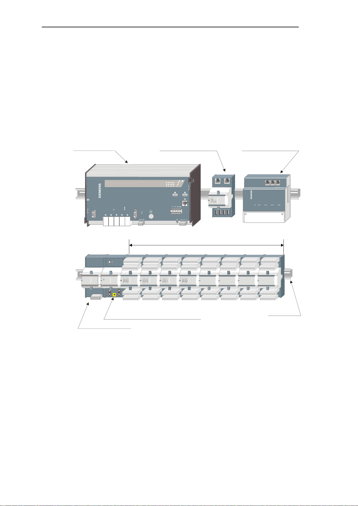
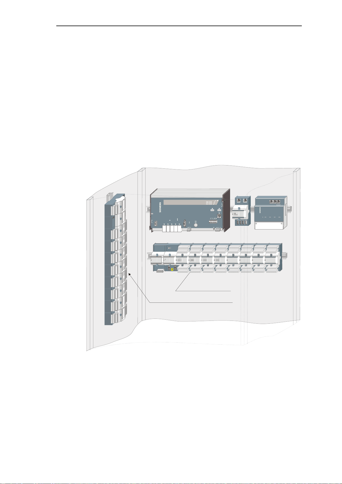
Peripheral control module (elektrical or optical)
Master control element
Bus interface module (electrical)
Bus interface module (optical)
1.1. Mechanical Design
A SICAM TM system consists of one master control element, up to a maximum of 4 bus
interface modules (electrical and/or optical) and up to 16 peripheral elements.
A peripheral element consists of a power supply module, a peripheral control module and up
to a maximum of 8 I/O-modules. The modules are fitted on a TS35 rail (DIN rail).
Optionally the master control element can be configured with up to 2 serial interface modules
(SIM) for the communication with other automation units or control systems.
TM1703 ACP CP-6014
SICAM
TB
P
X2
M-PRE/0
M-PRE/1
NC
FB
M-PRE/2
M-PRE/3
1 2 3 4 5 6
PWR
24-60VDC
Power supply module
Max. 8 I/O-modul es
TS35 rail
10 SICAM TM, Installation
Edition 10.2014, DC6-01 5-2.04
1.2. Configurations (Examples)
C
P-601
4
X
1X11X4X12
X14X16X15X1
3
WDE
R
X5X3X6X7X8X9X10
S
IM0
/PK/LK/LK
/PK
RXERxTXSI
3SI
2SI
1SI
0LO
C
FBM-PRE/2M-PRE/3M-PRE/0M-PRE/1NCTBPWR24-60VDCPUSH
TOUNLOC
K
ERCOMCPYRYRES
SI0SI2(FB)SI1(ETO)SI3
RELEASEPU
SHTOREL
EASEPUSHT
O
X
2
. . . .
. . . .
. . . .
. . . .
PS-663x
2
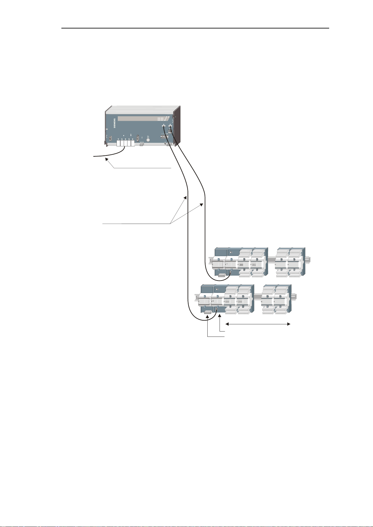
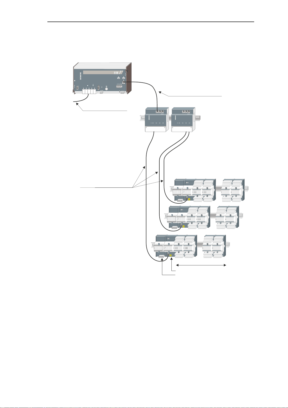
1.2.1. 2 Peripheral Elements SICAM TM, electrically connected
CP-6014
SICAM
TM1 703ACP
1 2 3 4 5 6
Communication with other
automation units
Architecture
Ax 1703 peripheral bus (electrical)
16 Mbps
USB cable, length up to 3 m
1
max. 8 I/O-modules
PE-6410
SICAM TM, Installation 11
DC6-015-2.04, Edition 10.2014
Architecture
014
X1X11X4X1
2X14X
16X
15X13
WDE
R
X
5X3X6X7X8X9X1
0
S
IM0
/
PK/
L
K
/
L
K
/
P
K
R
XERxTXSI3SI2SI1SI0LOC
PWR24
-
6
0VDCPUSHTOUNL
OCK
ERCOM
CPYRYRE
S
SI0SI2(FB)SI1
(ETO)SI
3
RELEASE
PUSHTOR
ELEASEP
USHTO
X
2
1 . . . 4
. . . .
. . . .
. . . .
. . . .
. . . .
. . . .
all in all up to 16 peripheral elements
PS-663x
16
1.2.2. 16 Peripheral Elements SICAM TM, electrically connected
SICAM
TM1703 ACP CP-6
TB
NC
Communication with other
automation units
Ax 1703 peripheral bus (electrical)
16 Mbps
USB cable, length up to 3 m
FB
M-PRE/2
M-PRE/3
M-PRE/0
M-PRE/1
1 2 3 4 5 6
CP-6014
Note:
Ax 1703 peripheral bus (electrical)
16 Mbps
patch cable, length up to 3 m
CM-0843
..........
max. 8 I/O-modules
PE-6410
15
1
12 SICAM TM, Installation
Edition 10.2014, DC6-01 5-2.04
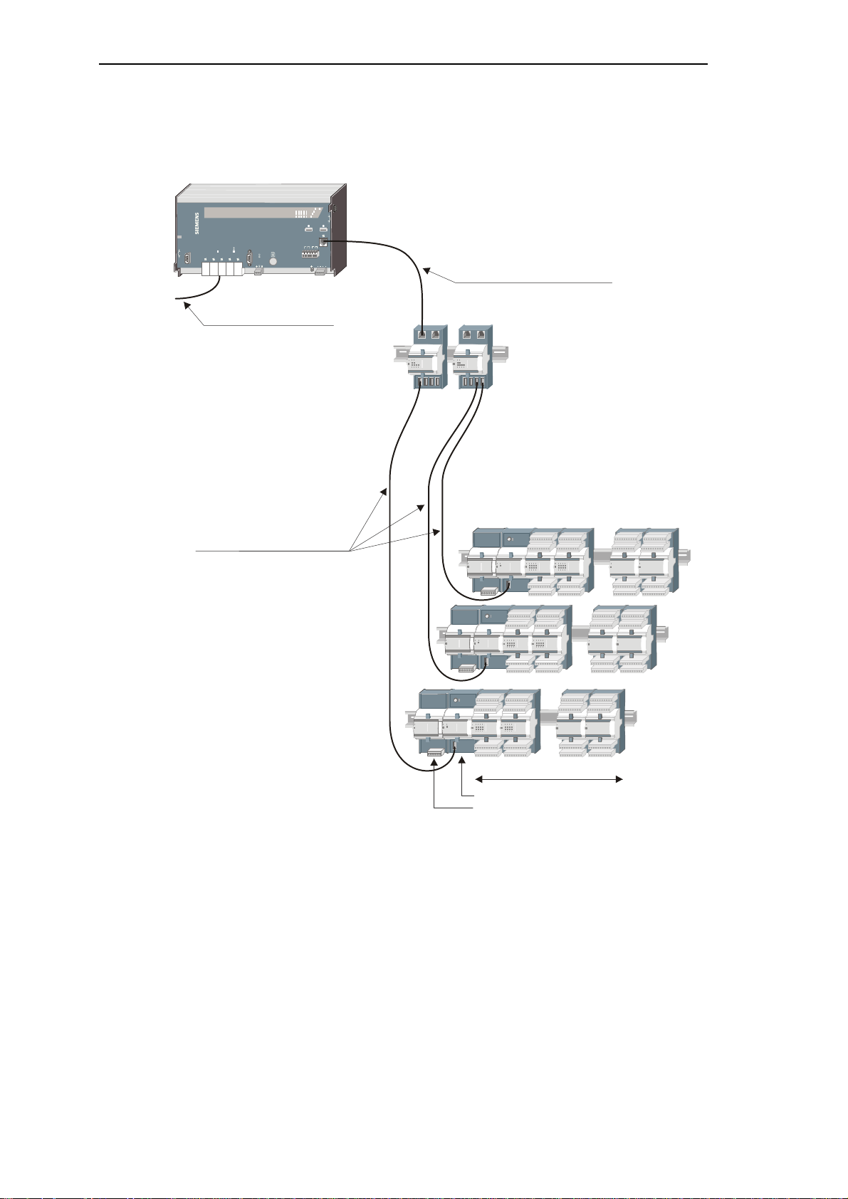
1.2.3. 16 Peripheral Elements SICAM TM, optically connected
SIC
A
M
170
3
014
X1X11X4X1
2X14X
16X
15X13
WDE
R
X
5X3X6X7X8X9X1
0
S
IM0
/
PK/LK/L
K
/
P
K
R
XERxTXSI3SI2SI1SI0LOC
PWR24
-60VDCPUSHTOUNL
OCK
ERCOM
CPYRYRE
S
SI0SI2(FB)SI1
(ETO)SI
3
RELEASE
PUSHTOR
ELEASEP
USHTO
X
2
SIC
A
M
170
3
. . . .
. . . .
. . . .
. . . .
. . . .
. . . .
all in all up to 16 peripheral elements
PS-663x
16
Architecture
SICAM
TM1703 ACP CP-6
TB
NC
Communication with other
automation units
Ax 1703 peripher al bus (optical)
16 Mbps, optical fibre,
length up to 200 m
FB
M-PRE/2
M-PRE/3
M-PRE/0
M-PRE/1
1 2 3 4 5 6
CP-6014
Note:
Ax 1703 peripheral bus (electrical)
16 Mbps
patch cable, length up to 3 m
1 . . . 4
CM-0842
..........
max. 8 I/O-modules
PE-6411
15
1
SICAM TM, Installation 13
DC6-015-2.04, Edition 10.2014
Architecture
0
1
4
X
1
X
11X4X
12X14X16X15X1
3
WDE
R
X5X3X6X7X8X9X
1
0
SIM
0
/
PK/LK/LK/
P
K
RXERxTX
S
I
3
S
I
2
S
I
1
S
I
0
LOC
P
W
R24-60VDCPUSHTOUNLO
C
K
ERCOMCP
YRY
RES
S
I0S
I2(FB)S
I1(
ETO)S
I
3
RELEASEPUSHTORELEASEPUSHT
O
X
2
. . . .
. . . .
. . . .
. . . .
. . . .
. . . .
PS-663x
16
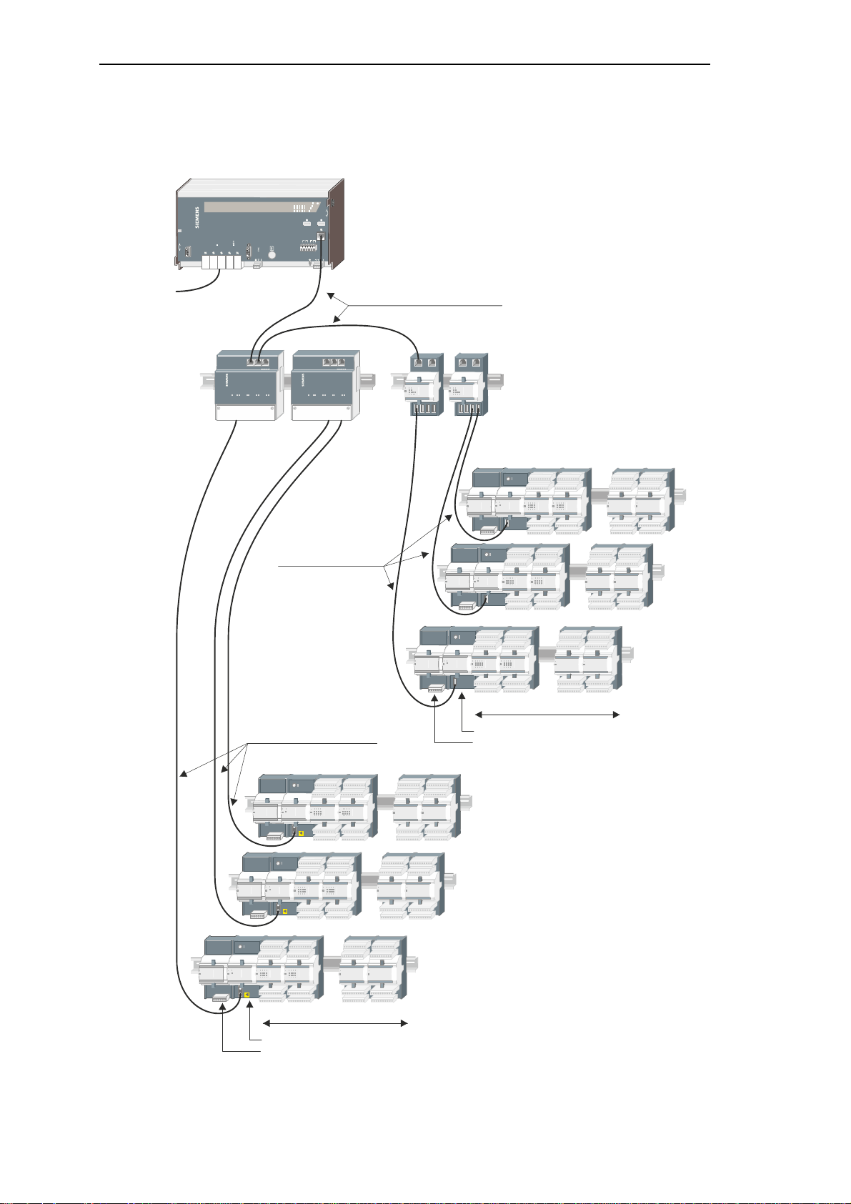
1.2.4. 16 Peripheral Elements SICAM TM, electrically and optically connected
SICAM
TM1703ACP CP-6
TB
NC
communication with other
automation units
FB
M-PRE/2
M-PRE/3
M-PRE/0
M-PRE/1
SICAM
1703
CM-0842
CP-6014
1 2 3 4 5 6
Ax 1703 peripheral bus (electrical)
16 Mbps
patch cable, length up to 3 m
1 . . . 4
SICAM
1703
Ax 1703 peripheral bus
(electrical)
16 Mbps
USB cable,
length up to 3 m
1 . . . 4
CM-0843
Note:
all in all up to 16 peripheral elements
15
Ax 1703 peripheral bus (optical)
16 Mbps, optical fibre,
length up to 200 m
. . . .
. . . .
..........
. . . .
. . . .
max. 8 I/O-modules
PE-6411
..........
9
max. 8 I/O-modules
PE-6410
PS-663x
. . . .
8
. . . .
7
1
14 SICAM TM, Installation
Edition 10.2014, DC6-01 5-2.04

2. Components
Content
2.1. Maste r Contro l Modules .................................................................................. 16
2.2. Serial Interface Modules ................................................................................. 17
2.3. Bus Interface Module ...................................................................................... 19
2.4. Powe r Supplies .............................................................................................. 19
2.5. Periphe ral Modules ......................................................................................... 20
SICAM TM, Installation 15
DC6-015-2.04, Edition 10.2014

Components
2.1. Master Control Modules
CP6014 Master Control Module GC6-014
Designation Item Number/ MLFB
6MF11130GA140A A0
16 SICAM TM, Installation
Edition 10.2014, DC6-01 5-2.04
2.2. Serial Interface Modules
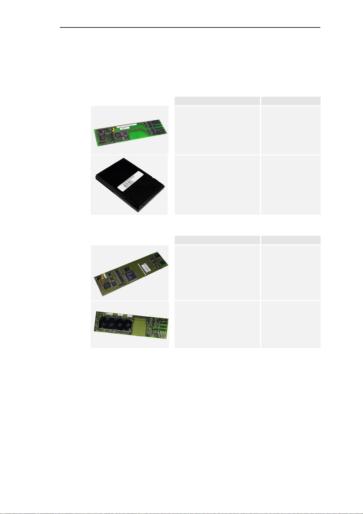
2.2.1. Serial Interface Processor (SIP)
SM-2551
Seria l Interfac e Pr ocessor 2 SI
Components
Designation Item Number/ MLFB
BC2-551
6MF101 30C F510 AA0
SM-0551
Seria l Interfac e Pr ocessor 1 SI
2.2.2. Network Interface Processor (NIP)
Designation Item Number/ MLFB
SM-2557
Network-Interf.Ethernet 2x100 TX
SM-2558 Ethernet-Interf. 1x100TX
+ 1 serial interface optional
BC0-551
6MF10130AF510AA0
BC2-557
6MF10130CF570AA0
BC2-558
6MF101 30CF580 AA0
SICAM TM, Installation 17
DC6-015-2.04, Edition 10.2014

Components
2.2.3. Field Bus Interface Processor (FIP)
Designation Item Number/ MLFB
SM-2545
Profibu s Interface (Mas ter)
BA2-54 5
6MF101 10C F4 50AA 0
18 SICAM TM, Installation
Edition 10.2014, DC6-01 5-2.04
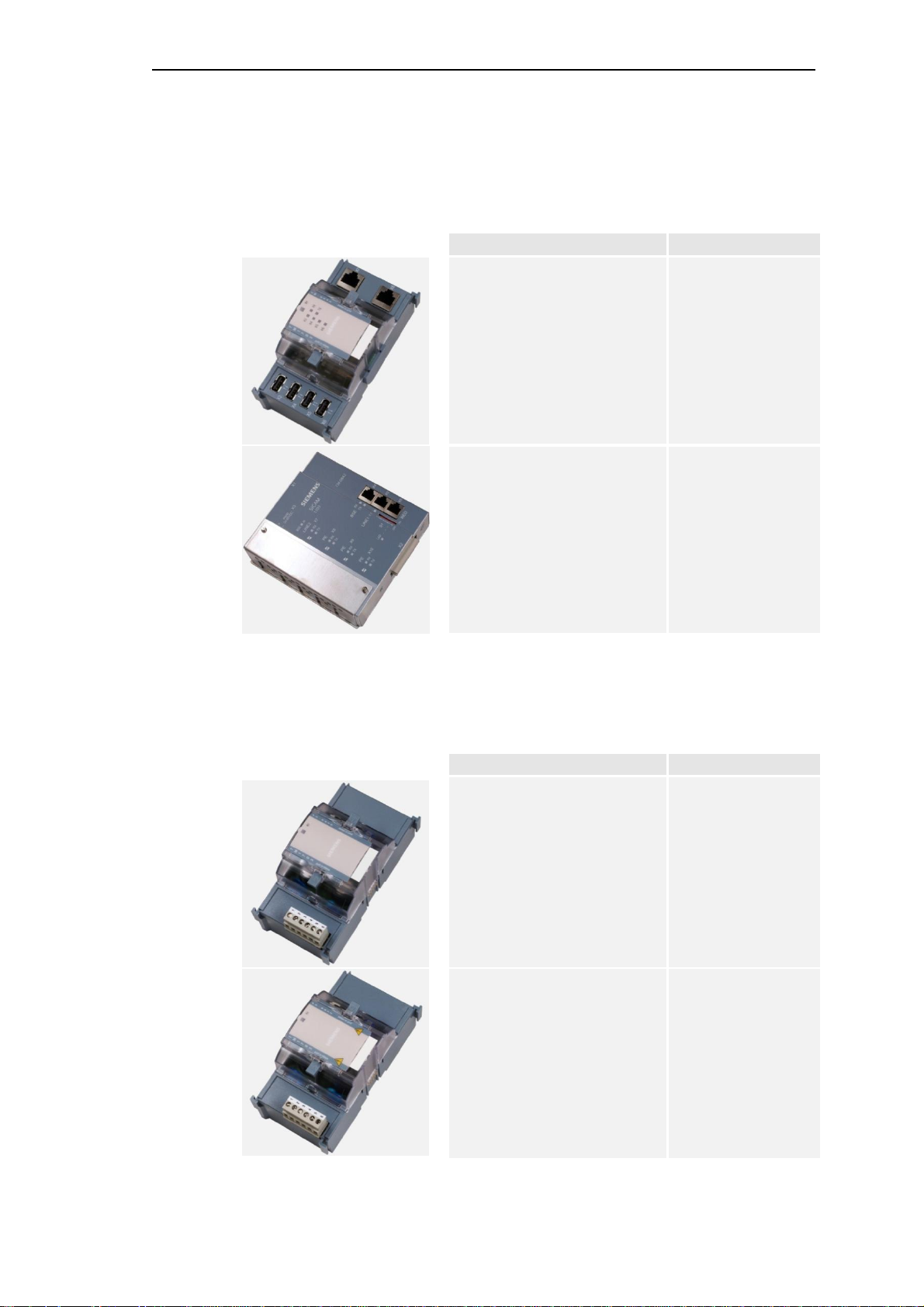
2.3. Bus Interface Module
Designation Item Number/ MLFB
CM-0843
Ax 1703 b us interface electrical
Components
GA0-843
6MF111 10AJ430AA0
2.4. Power Supplies
CM-0842
Ax 1703- Businterface 4x fiber optical
Designation Item Number/ MLFB
PS-6630 Power Supply Module
24-60 VDC (EMC+)
GA0-842
6MF111 10AJ420AA0
GC6-630
6MF11130GG300AA0
PS-6632 Power Supply Module
110-220 VDC (EMC+)
SICAM TM, Installation 19
DC6-015-2.04, Edition 10.2014
GC6-632
6MF11130GG320AA0

Components
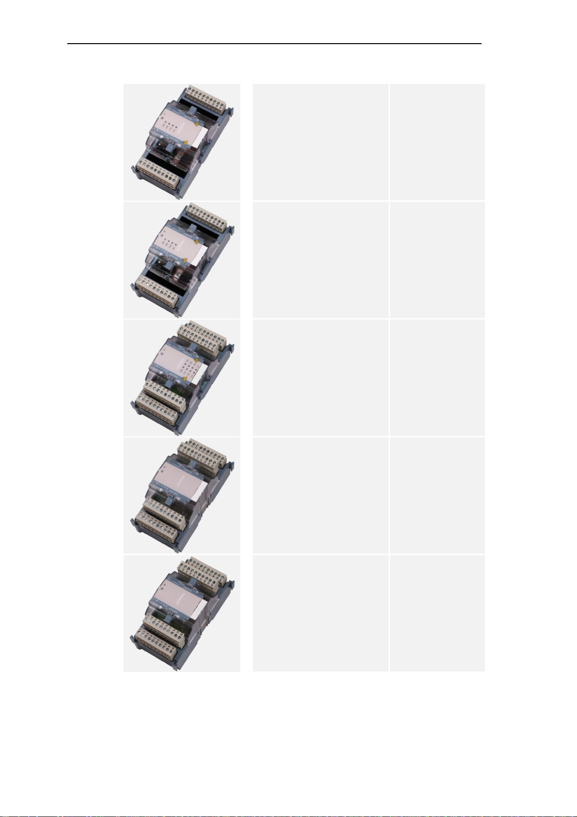
2.5. Peripheral Modules
PE-641 0 Peripher al Control Module
Ax-PE-Bus (electrical)
PE-641 1 Peripher al C ontroller
(1x Ax-PE bus opt)
PE-6412 Peripheriekopplung
(2x Ax-PE Bus opt)
GC6-410
6MF11130GE000AA0
GC6-411
6MF11130GE110AA0
GC6-412
6MF11130GE120AA0
DI-6100 Binary Input 2x8,
24-60VD C
DI-6101 Binary Input 2x8,
110/220VDC
GC6-100
6MF11130GB000A A0
GC6-101
6MF11130GB010A A0
20 SICAM TM, Installation
Edition 10.2014, DC6-01 5-2.04

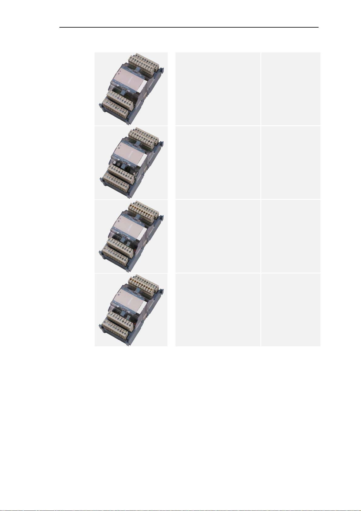
Components
DI-6102 Binary Input 2x8,
24-60VDC 1ms
DI-6103 Binary Input 2x8,
110/220 VD C 1ms
DI-610 4 Bin ary Input 2x8, 220VD C GC6-104
GC6-102
6MF11130GB020AA0
GC6-103
6MF111 30GB030A A0
6MF111 30GB040AA0
DO-6200 Binary Outp ut Tr ans is t or
2x8, 24-60 VD C
DO-6212 Binary Out put R el ays 8 x
24-220VD C/ 23 0VAC
GC6-200
6MF111 30GC000AA 0
GC6-212
6MF111 30GC200AA 0
SICAM TM, Installation 21
DC6-015-2.04, Edition 10.2014
Components
DO-6220 Command Out Basic
Module
DO-6221 Command Out Basic
Module Measure
DO-6230 Command Out Rela y
Module
GC6-220
6MF111 30G C200AA0
GC6-221
6MF11130GC210AA0
GC6-230
6MF111 30G C300AA0
AI-6300 Analog Input 2x2
±20mA/±1 0V
AI-6307 Analog Input 2x2 ±5mA GC6-307
GC6-300
6MF11130GD000AA 0
6MF111 30GD070AA 0
22 SICAM TM, Installation
Edition 10.2014, DC6-01 5-2.04
Components
AI-6310 Analog Input 2x2
Pt100/Ni100
AO-6380 Analog Output 4x
±20mA/±10mA/±10V
TE-6420 Speed Measurem ent 2x2
5VDC/24VDC/NAMUR
GC6-310
6MF11130GD100AA 0
GC6-380
6MF111 30GD 80 0AA0
GC6-420
6MF111 30GE200A A0
TE-6450 Position Acquisiti on 2x2
SSI/RS-422
GC6-450
6MF111 30GE500A A0
SICAM TM, Installation 23
DC6-015-2.04, Edition 10.2014


3. Assembly
Content
3.1. Necess ary Material ......................................................................................... 26
3.2. How an d wh e re ca n Installation ta ke place? ................................................... 27
3.3. Installat ion of TS35 Rail (DIN Rail) .................................................................. 30
3.4. Installat ion of Cable Duct ................................................................................ 31
3.5. Installat ion o f Mas ter Con tro l Ele ment ............................................................. 32
3.6. Installat ion o f Bus Inte r fa ce Mod ules .............................................................. 35
3.7. Installing TM Modules ..................................................................................... 37
SICAM TM, Installation 25
DC6-015-2.04, Edition 10.2014

Assembly
3.1. Necessary Material
Due to the different circumstances with the local installation of the SICAM TM systems, not all
details such as e.g. screw sizes, cable lengths and the like can be dealt with in this document.
Therefore only recommendations and minimum requirements are specified concerning
consumables.
The fitter himself must ensure that suitable materials and tools necessary for the installation
are available.
26 SICAM TM, Installation
Edition 10.2014, DC6-01 5-2.04
3.2. How and where can Installation take place?
SIC
A
M
170
3
S
ICA
M
TM1703ACPCP-601
4
X1X11X4X12X14X16X15X1
3
WDE
R
X5X3X6X7X8X
9X1
0
SIM
0
/PK/LK/LK/P
K
RXERxTXSI3SI2SI1SI0
LOC
FBM-PRE/2M-PRE/3M-PRE/0M-PRE/1NCTBPWR24-60VDCPUSHTOUNLOCK
ERCOMCP
YRYRE
S
SI0SI2(FB)SI1(ETO)SI3
RELEA
SEPUSHTOR
E
L
E
ASEPUSHTO
X
2
1 2 3 4 5 6
3.2.1. Installation Location
The terminal modules are designed for the in stallation in a cabinet, rack or on t he wall.
3.2.2. Installation Position
SICAM TM systems may only be installed horizontally or vertically. The vertical installation is
to be preferred, since this provides a considerably more space-saving and efficient
installation. The cabling of external cables is also made significantly easier as a result.
Assembly
horizontal installation
vertical installation
Not permissible are installations on the ceiling (own weight) and on the floor (dust level).
SICAM TM, Installation 27
DC6-015-2.04, Edition 10.2014
Assembly
306
141
63
80
8
0
SICAM
170
3
SICAM
TM1703ACPCP-601
4
X1X11X4X12X14X16X15X1
3
WDE
R
X
5
X3X6X7X8X
9X1
0
SIM
0
/PK/L
K/LK/PK
RXERxTXSI3SI2SI1SI0LO
C
F
BM-PR
E/2M-PR
E/3M-PR
E/0M-PR
E/1NCTBPWR24-60VDCPUSHTOUNLOC
K
E
RCOMCPYRYRE
S
S
I
0SI2(FB
)SI1(ETO)SI
3
RELEA
SEPUSHTORELEASEPUSHTO
X
2
630 (system with 8 I/O modules)
H
EIGHT(mm)
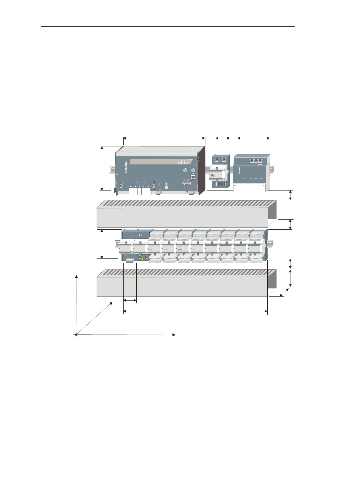
3.2.3. Space Requirement
The spac e requirem ent of a complet ely configured SICAM TM peripheral element ( power
supply, master control unit, up to 8 I/O modules) in the width co mes to 630 mm (without end
bracket and terminal strip marker for the system designation).
The space requirement for the height depends on several factors. Besides the size of the
module itself (130mm), the size of the cable ducts used and their minimum distance to the
modules is to be taken into account. This distance is 20 mm if no lead labeling is to take place
and 30 mm if the leads are to be fitted with labeling bushes.
155
1 2 3 4 5 6
20 or
30
20 or
30
130
20 or
30
HÖHE
63
)
m
m
(
H
T
P
E
D
WIDTH (mm)
28 SICAM TM, Installation
Edition 10.2014, DC6-01 5-2.04

3.2.4. Environmental Conditions
The permissible temperature range for the operation of the modules is about –25°....+70°C
(except CM-0842, only up to +55°C).
For details on the subject of environmental conditions, please refer to the SICAM TM System
Data Sheet (MC6-007-1), chapter: "Climatic Ambient Conditions and Electrical Ambient
Conditions".
Assembly
SICAM TM, Installation 29
DC6-015-2.04, Edition 10.2014

Assembly
3.3. Installation of TS35 Rail (DIN Rail)
For the installation of the modules a TS35 rail is used. This must conform to the European
standard EN 50 022.
The orientation and position in which the TS35 rail is to be installed must be determined
locally. Take into account the details specified in chapter 3.2 .3
, "Space Requirement"
Caution
By means of the connection TS35 rail - cabinet/rack a r eliable grounding connection must be guar anteed.
30 SICAM TM, Installation
Edition 10.2014, DC6-01 5-2.04
 Loading...