

Siemens SICAM RTU,SICAM AK 3 User Manual

Preface, Table of Contents
1
2
3
4
5
works
6
A
SICAM RTUs
SICAM AK 3
User Manual
Installation
System Components
Prepare Engineering
Engineering via SICAM TOOLBOX II
Service
Automation Units and Aut om ation Net-
Licensing Agreement
DC2-028-2.03

Hint
Disclaimer of Liability
for conformity with the hardware and software described, we cannot
included in the next releases. Any suggestions for improvement are
welcome.
Copyright
Please observe Notes and Warnings for your own safety in the Preface.
Although we have carefully checked the contents of this publication
guarantee complete conformity since errors cannot be excluded.
The information provided in this manual is checked at regular
intervals and any corrections that might become necessary are
Subject to change without prior notice.
Document Label: SICRTUs-BHBSICAMAK3-ENG_V2.03
Edition: 13.07.2016
Copyright © Siemens AG 2016
The reproduction, transmission or use of this document or its
contents is not permitted without express written authority. Offenders will be liable for damages. All rights, including rights created by
patent grant or registration of a utility model or design, are reserved.
Siemens AG Order Number: DC2-028-2.03
Energy Automation
Humbold ts traße 59
90459 Nürnberg
Germany

Preface
Purpose of this manual
This manual and describes the function and the manner of working of the system SICAM
AK 3. It is intended for sales and purchase purposes as well as for users.
The manual provides diverse ly detailed in formation and overviews:
• Installation of the board racks
• Installation of system components and and accessories
• Syst em components with interface descriptions and external circuitry
• Guideline for the engineering of the system
• Instructions for operation and maintenance
Target Group
This manual is intended for persons who are entrusted with installation, operation and service
of SICAM AK 3 systems.
Within this manual there are hints how to obtain information or files via the internet. If you
have no access please consult your project manager at Siemens.
Recommendations for Third-Party Products
Siemens does neither receive liability nor warranty for recommendations which are given or
implied by this manual. For the correct and intended use of the respective product the associated technical descriptions must be paid attention to in any case.
References to Third-Party Web Sites
Siemens is not responsible for the contents of third-party websites mentioned in this document, as well as the correctness of the publications and links. For all product information the
respective manufacturer is respons ib le.
SICAM RTUs, SICAM AK 3 User Manu al 3
DC2-028-2.03, Edition 07.2016

Preface
Placement into the Information Landscape
Document na me Item Numb er
SICAM AK 3 System Description MC2-021-2
SICAM RTUs Platforms ▪ Configuration Automation Units and Automation
Networks
SICAM RTUs ▪ Ax 1703 Common Functi ons Protocol Elements DC0-023-2
SICAM RTUs C ommon Func tions System and Basic System Elements DC0-015-2
SICAM RTUs Common Functions Peripheral Elements according
to IEC 60870-5-101/104
SICAM RTUs Safety Manu al DC0-117-2
Folder SICAM TOOLBOX II M30-001-3
SICAM RTUs IEC 60870-5-101/104 Interop erabilit y DC0-013-2
SICAM RTUs IEC 60870-5-1 03 Interoperability DC0-026-2
SICAM RTUs TG800 Interoperability DC0-041-2
SICAM RTUs DNP3 Interoperability DC0-046-2
SICAM RTUs MODBUS Interoperability DC0-073-2
Ax 1703 IEC 60870-5-101/104 Int er operability DA0-046-2
DC0-021-2
DC0-011-2
You find current product information on our website: www.siemens.com/sicam.
Further Support
For more information, please contac t our Customer Support Center:
Phone: +49 (0)180 524 70 00Fax: +49 (0)180 524 24 71
(charges depending on provider)
e-mail: support.ic@siemens.com
The Siemens Power Academy offer s a comprehensive pr ogram of pr ofess iona l trainin g event s
in the fields of power generation, distribution and transmission.
Main training centers are:
Nuremberg, Germany (Head Office)
Phone: +49 911 433 7415
Fax: +49 911 433 5482
power-academy.ptd@siemens.com
Schenectady, NY, USA
Phone: +1 518 395 5005
Fax: +1 518 346 2777
pti-edpro.ptd@siemens.com
Vienna, Austria
Phone: +43 51707 31143
Fax: +43 51707 55243
power-academy.at@siemens.com
Hebburn, United Kingdom
Phone: +44 1914 953449
Fax: +44 1914 953693
pti-training.stdl.uk@siemens.com
4 SICAM RTUs, SICAM AK 3 User Manu al
Edition 07.2016, DC2-02 8-2.03

Notes on Safety
This manual does not constitute a complete catalog of all safety measures required for operating the equipment (module, device) in question because special operating conditions might
require additional measures. However, it does contain notes that must be adhered to for your
own personal safety and to avoid damage to property. These notes are highlighted with a
warning triangle and different keywords indicating different degrees of danger.
Danger
means th at death, s erious bodily injur y or considerable pr operty dam age will occ ur, if the ap propriat e
precaut ionary meas ures are n ot carried out.
Warning
means that death, serious bodily injury or considerable pr operty dam age can occur, if th e appropriate
precaut ionary meas ures are n ot carried out.
Preface
Caution
means that minor bodily injury or property damage c ould occur, if the ap propriate precautionary measures
are not c arr ied out.
Hint
is important inf or mation about the product, th e handling of the pr oduct or the respect ive part of t he documentation, to which special attention is to be given.
Qualified Personnel
Commissioning and operation of the equipment (module, device) described in this manual
must be performed by qualified personnel only. As used in the safety notes contained in this
manual, qualified personnel are those p erso ns who are authorized to comm ission, release,
ground, and tag devices, systems, and electrical circuits in accordance with safety standards.
SICAM RTUs, SICAM AK 3 User Manu al 5
DC2-028-2.03, Edition 07.2016

Preface
Use as Prescribed
The equipment (device, module) must not be used for any other purposes than those described in the Catalog and the Technical Description. If it is used together with third-party devices and components, these must be recommended or approved by Siemens.
Correct and safe operation of the product requires adequate transportation, storage, installation, and mounting as well as appropriate use and maintenance.
During operation of electrical equipment, it is unavoidable that certain parts of this equipment
will carry dangerous voltages. Severe injury or damage to property can occur if the appropriate measures are not taken:
• Before m aking any connections at all, ground the equipment at the PE terminal.
• Hazardous voltages can be present on all switching components connected to the power
supply.
• Even after the supply voltage has been disconnected, hazardous voltages can still be present in the equipment (capacitor storage).
• Equipment with current transformer circuits must not be operated while open.
• The limit values indicated i n the manual or the operating instructions must not be exceed-
ed; that also applies to testing and commissioning.
Danger
Consider obligatory the safety rul es for the accomplishment of works at electrical plants:
1. Switch off electricity all-pole and on all sides!
2. Ensure that electricity cannot be switch ed on again!
3. Double check that no electrical current is flowing!
4. Discharge, ground, short circuit!
5. Cover or otherwise isolate compon ents that are still electric ally active!
Typographic and Sign Conventions
• Manuals to be referred to are represented in it al ics , such as e.g. SICAM RTUs Common
Functions System and Basic System Elements.
• F or easy reading , cer tain desig natio ns and n ames are pres ented in thi s fo nt
• Symbolic names are presented in this font
6 SICAM RTUs, SICAM AK 3 User Manu al
Edition 07.2016, DC2-02 8-2.03

Open Source Software
This product contains, among other things, Open Source Software developed by third parties.
The Open S ourc e Software used in this pro duct a nd th e licen se agreem ents conc erning this
software can be fou nd in the Readme_OSS. T hese O pen Sou rce Softw are fi les are pr otected
by copyright.
Your compliance with those license conditions will entitle you to use the Open Source Software as foreseen in the relevant license. In the event of conflicts between Siemens license
con diti ons and the Open Sourc e Software licen se conditions , the O pen Sou rce Softw are co nditions shall prevail with respect to the Open Source Software portions of the software. The
Open Source Software is licen sed r oyalty-free.
Insofar as the applicable Open Source Software License Conditions provide for it you can order the source code of the Open Source Software from your Siemens sales contact - against
payment of the shipping and handling charges - for a period of at least 3 years since purchase
of the Product.
We are liable for this product including the Open Source Software contained in it pursuant to
the license conditions applicable to the Product. Any liability for the Open Source Software
beyond the program flow intended for this product is explicitly excluded. Furthermore any liability for defects resulting from modifications to the Open Source Software by you or third parties is excluded. We do not provide any technical support for this Product if it has been modified.
SICAM RTUs, SICAM AK 3 User Manu al 7
DC2-028-2.03, Edition 07.2016

Open Source Software
8 SICAM RTUs, SICAM AK 3 User Manual
Edition 07.2016, DC2-02 8-2.03

Table of Contents
Open Source Software .................................................................................................... 7
1 Installation ................................................................................................................... 17
1.1 Mechan ical Design ......................................................................................... 18
1.1.1 CM-284 4 Bas ic Board Ra ck, 9 Slots ......................................................... 19
1.1.2 CM-284 6 Bas ic Board Ra ck, 17 Slo ts ....................................................... 19
1.1.3 CM-284 8 Bas ic Board Rack, 17 S lots ........................................................ 20
1.1.4 CM-284 3 Expan s ion Bo ard Ra ck, 16 Slots ................................................. 20
1.1.5 CM-284 7 Migrat ion Board Rac k, 17 Slo t .................................................... 2 1
1.2 Board Rack Installat ion ................................................................................... 22
1.2.1 Installat ion Location ................................................................................... 22
1.2.2 Space Requ irement ................................................................................... 22
1.2.2.1 CM-284 4 - Rear Panel Instal lat ion ........................................................ 23
1.2.2.2 CM-284 6 - Rear Panel Instal lat ion ........................................................ 24
1.2.2.3 CM-284 8 – Rear Pane l Insta llat ion ....................................................... 25
1.2.2.4 CM-2846, CM-2847, CM-2848 - 19" (Swing-) Frame Installation ........... 26
1.2.2.5 CM-284 3 - Rear Panel Instal lat ion ........................................................ 27
1.2.2.6 CM-284 3 - 19" (Swing-) Frame Instal lation ............................................ 28
1.2.2.7 Examples for 19" (Swing -) Fr ame Installation of 2 Board Racks ............ 29
1.2.3 Install Board Rack CM-28 44 ...................................................................... 30
1.2.4 Install Board Ra ck CM-2 84 6, CM-28 43 and CM-2 848 ................................ 32
1.2.4.1 19" (Swing) Frame Insta llation .............................................................. 3 2
1.2.4.2 Rear Panel Assembly ........................................................................... 34
1.3 Installat ion an d Re mo va l of Modu les .............................................................. 36
1.3.1 Preparations .............................................................................................. 36
1.3.1.1 Conne ct and put on Ground ing Strap .................................................... 36
1.3.1.2 Removin g Fron t Pane l .......................................................................... 37
1.3.2 Installation ................................................................................................. 37
1.3.3 Removal .................................................................................................... 38
1.3.4 Mounting Fron t Panel ................................................................................ 39
1.4 Setup of external Commun ication Con nect ions ............................................... 4 0
1.4.1 General ..................................................................................................... 40
1.4.2 Installat ion o f a Serial Inte r face Mod ule ...................................................... 41
1.4.3 Assign men t of the Commun ica t ion Inte r faces ............................................ 42
1.4.4 Glue Serial Nu mber on Fron t Pane l ........................................................... 43
1.4.5 Commun ication Cabling ............................................................................. 43
1.4.5.1 Serial Communica tion........................................................................... 44
1.4.5.1.1 Point-to -Point Traffic/Mu lti-Po int Traffic ............................................ 44
1.4.5.1.2 Multi-Po int Tra ffic via Glas s Fibe r Optic and Sta r Conne ction ........... 47
1.4.5.1.3 Analog Dial-Up Traffic ...................................................................... 48
1.4.5.1.4 Dial-up Traffic Analog /GSM/ ISDN .................................................... 5 2
SICAM RTUs, SICAM AK 3 User Manu al 9
DC2-028-2.03, Edition 07.2016

Table of Contents
1.4.5.1.5 Dial-Up Traffi c GSM......................................................................... 54
1.4.5.1.6 Serial co mmunication with DMS (Digital Mu lt iplex Sys te m) .............. 56
1.4.5.1.7 Serial communication – Direct connect ion with RS -23 2 .................... 5 8
1.4.5.2 LAN Communica tion (Ethern et TCP/IP) ................................................ 60
1.4.5.3 Field bus Commun ica tion (PRO FIBU S-DP) .......................................... 61
1.4.6 Cable Routing ........................................................................................... 63
1.5 Wiring for the Rece ption of Time Signals ........................................................ 64
1.5.1 DCF77 Recei ver ........................................................................................ 64
1.5.2 GPS Satellite Receiver .............................................................................. 66
1.5.2.1 Wiring for th e Rece ipt of the Minute Pu ls e ............................................ 66
1.5.2.2 Wiring for th e Rece ipt of the Seria l Time S ign a l .................................... 6 7
1.5.3 LAN Time Server ....................................................................................... 69
1.6 Wiring Watchd og and Error ............................................................................. 70
1.6.1 General ..................................................................................................... 7 0
1.7 Powe r Supply ................................................................................................. 71
1.7.1 General ..................................................................................................... 7 1
1.7.2 Possible Configura tions ............................................................................. 71
1.7.3 Install Power Supply .................................................................................. 72
1.7.3.1 Installing First Power Supply ................................................................. 72
1.7.3.2 Installing Secon d Pow er Supply ............................................................ 73
1.7.4 Wiring of the Powe r Supply ........................................................................ 73
1.8 Wiring Proces s Periphe rals ............................................................................. 7 4
1.8.1 General ..................................................................................................... 7 4
1.8.2 Fitting Periph eral Cable ............................................................................. 74
1.8.3 Removing Periph eral Cable ....................................................................... 76
1.8.4 PIN Assignment Periph eral Cable .............................................................. 77
1.9 Shielding and Pro tecti ve Earthing ................................................................... 81
1.9.1 Shielding ................................................................................................... 81
1.9.2 Protect ive Earthing / Grounding ................................................................. 81
1.10 Labeling ......................................................................................................... 82
1.10.1 Genera l ..................................................................................................... 82
1.11 Switching the Syste m On and Off ................................................................... 83
1.11.1 Switching On ............................................................................................. 83
1.11.2 Switching Off ............................................................................................. 83
2 System Components ................................................................................................... 85
2.1 Powe r Supply ................................................................................................. 86
2.1.1 PS-2630 , PS-263 2..................................................................................... 86
2.1.1.1 Front View ............................................................................................ 86
2.1.1.2 Block Diagram ...................................................................................... 87
2.1.1.3 Pin Assignmen t .................................................................................... 89
2.2 Basic System Elements .................................................................................. 90
2.2.1 CP-201 6/CPCX26 ..................................................................................... 9 0
2.2.1.1 Front Panel........................................................................................... 9 0
10 SICAM RTUs, SICAM AK 3 User Manu al
Edition 07.2016, DC2-02 8-2.03

Table of Contents
2.2.1.2 Block Diagram ...................................................................................... 91
2.2.1.3 Pin Assignmen t .................................................................................... 92
2.2.1.4 LED Display ......................................................................................... 94
2.2.2 CP-201 9/PCCX26 ..................................................................................... 9 5
2.2.2.1 Front Panel ........................................................................................... 95
2.2.2.2 Block Diagram ...................................................................................... 96
2.2.2.3 Pin Assignmen t .................................................................................... 97
2.2.2.4 LED Displays : ....................................................................................... 98
2.3 Migration -Bas ic System Element .................................................................... 99
2.3.1 CP-201 7/PCCX25 ..................................................................................... 9 9
2.4 Protoco l Elemen ts ........................................................................................ 10 0
2.4.1 SM-2551 ................................................................................................. 101
2.4.1.1 Block Diagram .................................................................................... 10 1
2.4.1.2 Pin Assignmen t .................................................................................. 10 2
2.4.1.2.1 Unbalan ced Interchan ge Circuit V.24/V.28 ..................................... 102
2.4.1.2.2 Balance d Interchang e Circuit X.24 /X.27 ......................................... 102
2.4.1.2.3 Balance d Interface EIA-485 ........................................................... 103
2.4.1.2.4 Balance d Interface EIA-422 ........................................................... 103
2.4.1.2.5 Optical Inter fa ce (Mu ltimod e Fibe r Opt ics) w ith CM-082 1 ............... 103
2.4.1.2.6 Optical Inter fa ce (Mu ltimod e Fibe r Opt ics) w ith CM-084 7 ............... 104
2.4.2 SM-0551 ................................................................................................. 105
2.4.2.1 Block Diagram .................................................................................... 10 5
2.4.2.2 Pin Assignmen t .................................................................................. 10 6
2.4.2.2.1 Unbalan ced Interchan ge Circuit V.24/V.28 ..................................... 106
2.4.2.2.2 Balance d Interchang e Circuit X.24 /X.27 ......................................... 106
2.4.2.2.3 Balance d Interface EIA-485 ........................................................... 107
2.4.2.2.4 Balance d Interface EIA-422 ........................................................... 107
2.4.2.2.5 Optical Inter fa ce (Mu ltimod e Fibe r Opt ics) w ith CM-082 1 ............... 107
2.4.2.2.6 Optical Inter fa ce (Mu ltimod e Fibe r Opt ics) w ith CM-084 7 ............... 108
2.4.3 SM-2558 ................................................................................................. 109
2.4.3.1 Block Diagram .................................................................................... 10 9
2.4.3.2 Pin Assignmen t .................................................................................. 11 0
2.4.3.2.1 Etherne t Interface .......................................................................... 110
2.4.3.2.2 Serial Interface .............................................................................. 11 0
2.5 Periphe ral Elemen ts ..................................................................................... 11 1
2.5.1 Setting the Module Address ..................................................................... 111
2.5.2 DI-211x/BISX26 ....................................................................................... 112
2.5.2.1 Front Panel ......................................................................................... 112
2.5.2.2 Block Diagram .................................................................................... 11 3
2.5.2.3 Pin Assignmen t .................................................................................. 11 4
2.5.2.4 Externa l Circuitry ................................................................................ 115
2.5.2.5 I/O Assignmen t ................................................................................... 116
2.5.2.5.1 Inputs ............................................................................................ 116
2.5.2.6 Return In forma tion to Puls e Comman d As s ignmen t ............................ 117
SICAM RTUs, SICAM AK 3 User Manu al 11
DC2-028-2.03, Edition 07.2016

Table of Contents
2.5.3 DO-2201 /BISO25 .................................................................................... 118
2.5.3.1 Front Panel......................................................................................... 1 18
2.5.3.2 Block Diagram .................................................................................... 11 9
2.5.3.3 Pin Assignmen t .................................................................................. 12 0
2.5.3.4 Externa l Circuitry ................................................................................ 121
2.5.3.5 I/O Assignmen t ................................................................................... 124
2.5.3.5.1 Outputs ......................................................................................... 124
2.5.4 DO-2210 /PCCO2x, DO-2211 /PCCO2x .................................................... 125
2.5.4.1 Front Panel......................................................................................... 1 25
2.5.4.2 Block Diagram .................................................................................... 12 6
2.5.4.3 Pin Assignmen t .................................................................................. 12 7
2.5.4.4 Externa l Circuitry ................................................................................ 128
2.5.4.5 I/O Assignmen t ................................................................................... 138
2.5.4.5.1 Outputs ......................................................................................... 138
2.5.4.6 Return In forma tion to Puls e Comman d As s ignmen t ............................ 140
2.5.5 AI-2300 /PASI25 , AI-230 2/PASI25 , AI-230 3/PASI2 5 ................................. 141
2.5.5.1 Front Panel......................................................................................... 1 41
2.5.5.2 Block Diagram .................................................................................... 14 2
2.5.5.3 Pin Assignmen t .................................................................................. 14 3
2.5.5.4 Externa l Circuitry ................................................................................ 144
2.5.5.5 I/O Assignmen t ................................................................................... 145
2.5.5.5.1 Inputs ............................................................................................ 145
2.5.5.5.2 Outputs ......................................................................................... 145
2.6 Migration -Periphera l Elements ...................................................................... 146
2.7 Submodules ................................................................................................. 147
2.7.1 Glue Serial Nu mber on Fron t Pane l ......................................................... 1 47
2.7.2 SM-0570 ................................................................................................. 147
2.7.2.1 Block Diagram .................................................................................... 14 8
2.7.2.2 Conne ctor to Carrier Module ............................................................... 148
2.7.2.3 Externa l Circuitry ................................................................................ 149
2.7.3 SM-0571 ................................................................................................. 149
2.7.3.1 Block Diagram .................................................................................... 15 0
2.7.3.2 Conne ctor to Carrier Module ............................................................... 150
2.7.3.3 Externa l Circuitry ................................................................................ 151
2.7.4 SM-0572 ................................................................................................. 152
2.7.4.1 Block Diagram .................................................................................... 15 3
2.7.4.2 Conne ctor to Carrier Module ............................................................... 153
2.7.4.3 Externa l Circuitry ................................................................................ 154
2.7.5 SM-0574 ................................................................................................. 155
2.7.5.1 Block Diagram .................................................................................... 15 6
2.7.5.2 Conne ctor to Carrier Module ............................................................... 156
2.7.5.3 Externa l Circuitry ................................................................................ 157
2.8 Bus Interface Modules .................................................................................. 158
2.8.1 CM-084 3 ................................................................................................. 15 8
12 SICAM RTUs, SICAM AK 3 User Manu al
Edition 07.2016, DC2-02 8-2.03

Table of Contents
2.8.1.1 Front Panel ......................................................................................... 158
2.8.1.2 Block Diagram .................................................................................... 15 9
2.8.1.3 Pin Assignmen t and Disp lay ............................................................... 160
2.8.1.4 Configu ration (Example) ..................................................................... 161
2.8.2 CM-084 2 ................................................................................................. 16 2
2.8.2.1 Front Panel ......................................................................................... 162
2.8.2.2 Configu rat ion Switch S1 ..................................................................... 162
2.8.2.3 Pin Assignmen t and Disp lay ............................................................... 163
2.8.2.4 Configu ration (Examp les) ................................................................... 1 64
3 Prepar e Engine ering ................................................................................................. 167
3.1 Enginee ring Tool SICAM TOOLBOX II .......................................................... 1 68
3.1.1 Softwa re for the Engineering .................................................................... 168
3.1.2 Prerequ isites ........................................................................................... 169
3.2 Conne ct Engineering PC with a Target Syste m ............................................. 17 0
3.2.1 Physica l Connection ................................................................................ 170
3.2.1.1 Directly via the USB Inter face ............................................................. 170
3.2.1.2 Remote ope ration , LAN/ WAN via Ethern et (TCP /IP) ........................... 17 1
3.2.2 Logical Connection .................................................................................. 172
3.3 Integra ted Protoco l SNMPv3 ........................................................................ 173
3.3.1 Downloa d of the SICAM RTUs MIB-Fi les ................................................. 17 3
3.3.2 Import of the MIB-Files in MIB-Brow se r .................................................... 173
3.3.3 Display of SNMP-Var iab les in MIB-Brow se r ............................................. 174
3.4 SD Card ....................................................................................................... 1 76
3.4.1 SD Card Read er/Writer ............................................................................ 1 76
3.5 Loada ble Firmwares ..................................................................................... 177
3.6 Working w ith the SICAM TOOL BOX II .......................................................... 178
3.6.1 Enginee ring Procedure ............................................................................ 178
3.6.2 Structure of the User Interface ................................................................. 17 9
4 Engineer ing via SICA M TOOLBOX I I ........................................................................ 181
4.1 Telecontro l ................................................................................................... 182
4.1.1 Presets .................................................................................................... 184
4.1.1.1 Users and Rights ................................................................................ 184
4.1.1.2 Passw ord ........................................................................................... 18 5
4.1.1.3 Language ........................................................................................... 185
4.1.2 Entrance into the Projec t .......................................................................... 185
4.1.2.1 Logon ................................................................................................. 185
4.1.2.2 Logoff ................................................................................................. 186
4.1.2.3 Chang e Passw ord .............................................................................. 186
4.1.3 Plant Configu ration .................................................................................. 186
4.1.4 Import firmwa re ....................................................................................... 187
4.1.5 Paramete riza tion of the Telecontro l Functiona lity ..................................... 1 87
4.1.5.1 Hardw are Configuration ...................................................................... 188
SICAM RTUs, SICAM AK 3 User Manu al 13
DC2-028-2.03, Edition 07.2016

Table of Contents
4.1.5.2 System- Technica l Settings ................................................................. 1 89
4.1.5.2.1 Communication.............................................................................. 189
4.1.5.2.2 Periphery ....................................................................................... 189
4.1.5.3 Proces s-Te chnica l Setting s ................................................................ 19 0
4.1.5.3.1 Levels ............................................................................................ 190
4.1.5.3.2 Types ............................................................................................ 190
4.1.5.3.3 Images .......................................................................................... 1 91
4.1.5.4 Decen tralized Archi ving (DEAR) ......................................................... 1 92
4.1.6 Transfor m Para meters ............................................................................. 192
4.1.7 Import, Export an d Backup of Engine er ing Data ....................................... 192
4.1.8 Documenta tion ........................................................................................ 192
4.1.8.1 Hardw are Configuration ...................................................................... 193
4.1.8.2 Assembly Techn ique .......................................................................... 19 3
4.1.8.3 Interface to ELCAD ............................................................................. 193
4.1.8.4 Telecontro l Function ........................................................................... 194
4.1.8.4.1 System- technica l Parameter .......................................................... 194
4.1.8.4.2 Proces s-Tech nical Settings............................................................ 1 94
4.1.9 Commiss ioning an Test ........................................................................... 194
4.1.9.1 Loading Eng ineering Data .................................................................. 194
4.1.9.2 Parame ter Compariso n....................................................................... 195
4.1.9.3 Test Function s .................................................................................... 196
4.1.9.3.1 Status Of Spontane ous Data Points ............................................... 19 6
4.1.9.3.2 Simulat ion of Spon tan eo us Da ta Points ......................................... 19 7
4.1.9.3.3 Check The Conne ction To Auto mation Un its .................................. 197
4.1.9.4 Display ing Decentra l Archi ve (DEAR) ................................................. 198
4.2 Automation ................................................................................................... 199
4.2.1 Create Funct ion Diag ra m (FUD) .............................................................. 200
4.2.1.1 Configu ring Externa l Signals ............................................................... 200
4.2.1.2 Tool CAEx plus................................................................................... 201
4.2.1.3 Genera te Code ................................................................................... 202
4.2.2 Documenta tion ........................................................................................ 203
4.2.2.1 Cross Reference List .......................................................................... 203
4.2.2.2 Open/Clos ed-L oop Control Func tion ................................................... 20 3
4.2.3 Commiss ioning and Test ......................................................................... 204
4.2.3.1 Loading Prog ram Code ....................................................................... 204
4.2.3.2 Test Function s .................................................................................... 204
4.2.3.2.1 Simulate Funct ion Diagram Offline ................................................. 20 4
4.2.3.2.2 CAEx plus Online Test ................................................................... 205
5 Service ....................................................................................................................... 207
5.1 Operation And Dis play Ele ments .................................................................. 208
5.1.1 Powe r Supply .......................................................................................... 208
5.1.2 Basic System Elements ........................................................................... 208
5.1.3 Periphera l Elements ................................................................................ 2 12
14 SICAM RTUs, SICAM AK 3 User Manu al
Edition 07.2016, DC2-02 8-2.03

Table of Contents
5.2 Checks And Syste m Displays ....................................................................... 21 3
5.2.1 Basic System Elements ........................................................................... 213
5.2.2 Protocol Elemen ts ................................................................................... 21 7
5.2.3 Periphera l Elements ................................................................................ 2 18
5.3 Diagno sis ..................................................................................................... 21 9
5.3.1 Distinct ion of the Error Types ................................................................... 219
5.3.2 Conne ction Pos sibilit ies for the Service .................................................... 219
5.3.3 System Diagno sis .................................................................................... 222
5.3.4 System Performance ............................................................................... 224
5.3.5 Diagnos is of the Open-/Clos ed -Lo op Contro l Function ............................. 22 5
5.4 Maintena nce of the Hardw are ....................................................................... 227
5.4.1 Recogn ition of Hardw are Errors ............................................................... 227
5.4.1.1 Modules ............................................................................................. 227
5.4.1.2 SD Card ............................................................................................. 227
5.4.2 Guideline for the Replacemen t of Modules ............................................... 228
5.4.2.1 Maste r control ele ment ....................................................................... 228
5.4.2.2 Proces sing and Communication Elemen t(s) ........................................ 229
5.4.2.3 Serial Interface Module ....................................................................... 2 29
5.4.2.4 Periphe ral Elements ........................................................................... 2 29
5.5 Firmware Update .......................................................................................... 230
5.5.1 Procedure................................................................................................ 230
5.5.1.1 Interrog ation o f Firmw are Re vision ..................................................... 231
5.5.1.2 Import of Fir mwa re in to th e SICA M TO OLBOX II ................................ 231
5.5.1.3 Loading of Firmw are into the Targ et Sys te m ....................................... 231
5.5.1.3.1 Load Firmware Onl ine.................................................................... 232
5.5.1.3.2 Load Firmware Offline .................................................................... 232
5.5.2 Errors with Loa ding o f Firmw are .............................................................. 233
5.6 Remote Mainte nance ................................................................................... 234
5.6.1 Configura t ion of Ser ver and Clien ts .......................................................... 234
6 Automa tio n Units and A utoma ti on Netw ork s .......................................................... 235
6.1 Configu rat ion of Automat ion Units ................................................................. 236
6.1.1 SICAM AK3 Basic Uni t with Periphe ra l Elemen ts ..................................... 236
6.1.1.1 SICAM AK 3, local PE ........................................................................ 236
6.1.1.2 SICAM AK 3 - SICAM AK 3 PE, electr ica lly con ne cte d ........................ 237
6.1.1.3 SICAM AK 3 - SICAM TM PE, opt ica l ly conne cted .............................. 238
6.1.1.4 SICAM AK 3 - SICAM TM PE, optica l, mul t i-hie ra rc hical ..................... 240
6.1.1.5 SICAM AK 3 - SICAM AK 3 PE, electrical and optical.......................... 242
6.2 Applica tion/C on figurat ion of the local Ethern et Inter faces .............................. 2 44
6.2.1 SICAM AK 3 „Stand-a lone “ Teleco ntro l Stat ion ........................................ 245
6.2.2 SICAM AK 3 as Telecontro l Subs tation .................................................... 24 6
6.2.3 SICAM AK 3 as Telecontrol Substation with Node Function (Protocol
Converter) ............................................................................................... 247
SICAM RTUs, SICAM AK 3 User Manu al 15
DC2-028-2.03, Edition 07.2016

Table of Contents
6.2.4 SICAM AK 3 as Telecontrol Substation with integrated Switch for External
System connection .................................................................................. 248
6.2.5 SICAM AK 3 as Telecontrol Substation with integrated Switch for SICAM
TOOLBOX II connection .......................................................................... 249
6.3 Applica tion /C on figura t ion o f Static Route s ................................................... 250
6.3.1 General ................................................................................................... 2 50
6.3.2 Configuration ........................................................................................... 250
6.3.3 Example A ............................................................................................... 251
6.3.4 Example B ............................................................................................... 252
6.4 Applica tion /Co n figura tion o f IPSEC VP N ...................................................... 253
6.4.1 SICAM AK 3 as Telecontrol Substation with IPSec VPN via fixed Network254
6.4.2 SICAM AK 3 as Telecontrol Substation with IPSec VPN via GPRS Router
and ADSL netwo rk................................................................................... 255
6.4.3 SICAM AK 3 as Telecontrol Substation with IPSec VPN via GPRS Network256
A Licensi ng A greement ................................................................................................ 25 7
A.1 Open Source So ftw are us ed in SICAM AK 3 ................................................. 257
A.1.1 Reado ut of ReadmOS S.h tm .................................................................... 2 57
16 SICAM RTUs, SICAM AK 3 User Manu al
Edition 07.2016, DC2-02 8-2.03

1 Installation
Contents
1.1 Mechan ical Design ......................................................................................... 18
1.2 Board rack Installation .................................................................................... 22
1.3 Installat ion an d Re mo va l of Modu les .............................................................. 36
1.4 Setup of external Commun ication Con nect ions ............................................... 4 0
1.5 Wiring for the Rece ption of Time Signals ........................................................ 64
1.6 Wiring Watchdog and Error ............................................................................. 70
1.7 Powe r Supply ................................................................................................. 71
1.8 Wiring Process Peripherals ............................................................................. 7 4
1.9 Shielding and Pro tecti ve Earthing ................................................................... 8 1
1.10 Labeling ......................................................................................................... 82
1.11 Switching the Syste m On and Off ................................................................... 83
This chapter describes the structure of the system SICAM AK 3, how and where it may be installed, and how the wirings are to be accomplished.
SICAM RTUs, SICAM AK 3 User Manu al 17
DC2-028-2.03, Edition 07.2016
Installation
SICAM AK
PS-263x
DI-2110
DO-2210
AI-2300
CP-2019
AI-2301
AI-2301
DI-2110
DI-2110
Mount ing rack
Power supply
SICAM AK
PS-263x
DI-2110
DO-2210
AI-2300
CP-2019
AI-2301
DI-2110
DI-2110
Mounting rack CM-2848
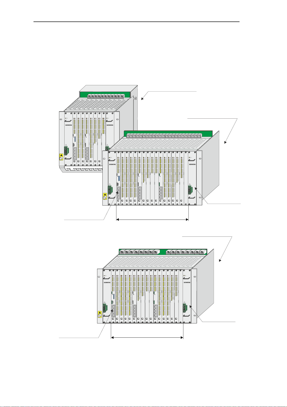
1.1 Mechanical Design
The system SICAM AK 3 consists of a board rack in double euro format with slots for the seating of modules and power supplies.
CM-2844
PS-263x CP-2016 DI-2110 DI-2110 CP-2019 DO-2210 AI-2301 AI- 2300
SICAM AK
Master control el ement
PS-263xDI-2110
SICAM AK
PS-263x
CP-2016 DI-2110 DO-2210 AI-2300 CP-2019
SICAM AK
DI-2110
DI-2110
AI-2301
Slots for modules
Mounti ng rack CM- 2846
18 SICAM RTUs, SICAM AK 3 User Manu al
PS-263x
CP-2016 DI -2110 DO-2210 AI-2300 CP-2019 AI-2301 DI-2110
SICAM AK
DI-2110
AI-2301
Power supply
Master control element
Slots for modules
There are 3 different sized board racks available, as well as 1 expansion board rack.
Edition 07.2016, DC2-02 8-2.03
1.1.1 CM-2844 Basic Board Rack, 9 Slots
The basic board rack CM-2844 has 9 slots for modules and 2 slots for power supplies in double euro format. It serves for the equipment of basic modules and peripheral modules.
Installation
It can be used for rear panel assembly. In section 1.2.2, Space Requirement you can find in-
formation on the dimensions.
Further information can be found in the SICAM AK 3 System Description.
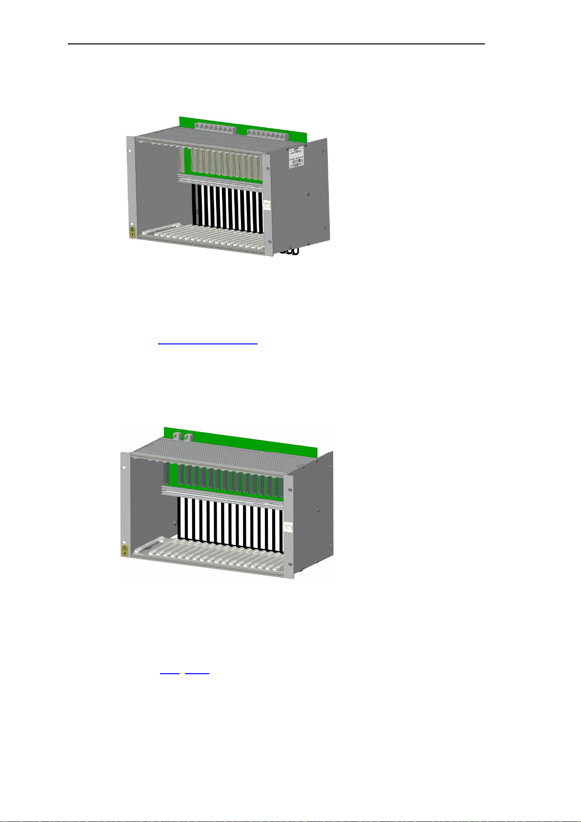
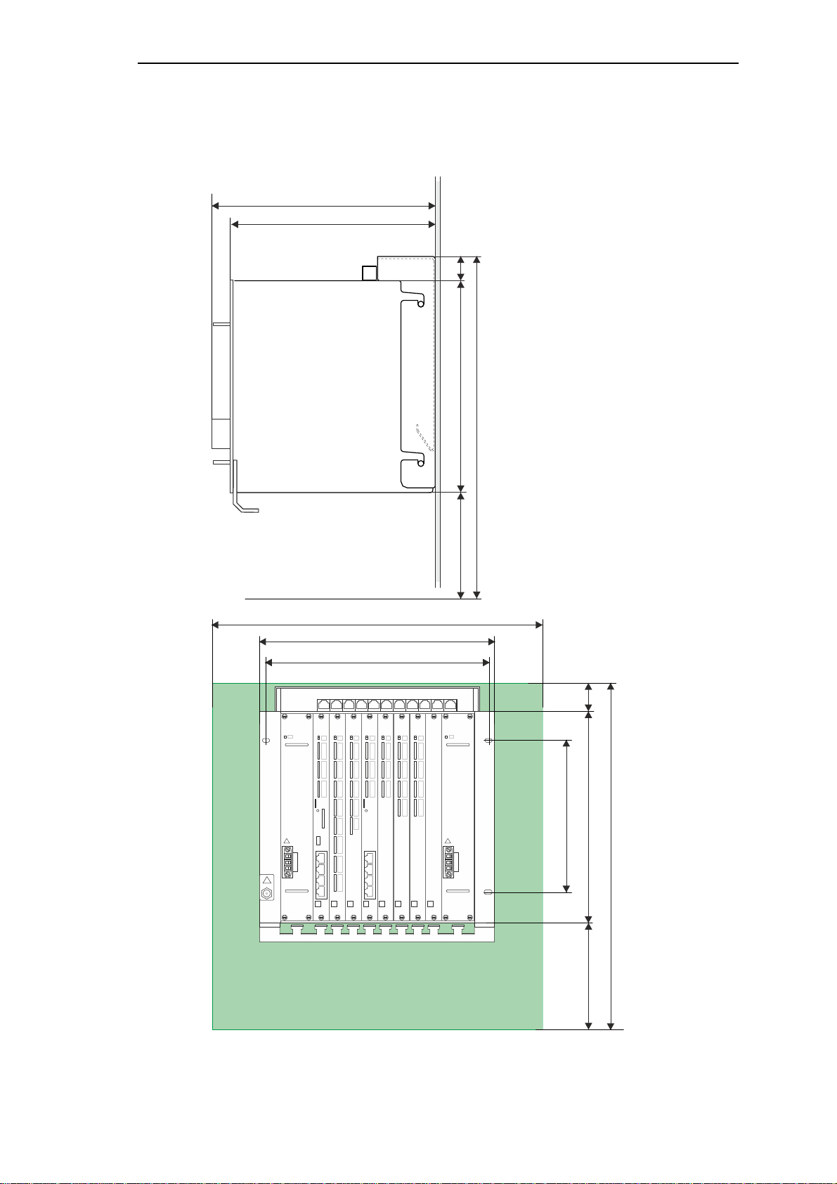
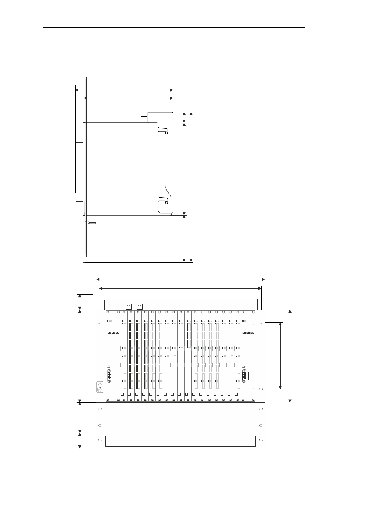
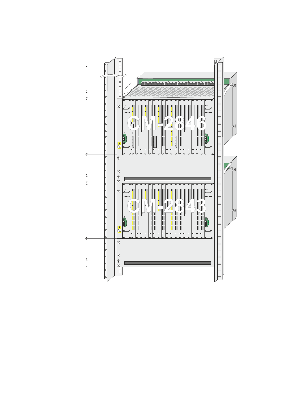
1.1.2 CM-2846 Basic Board Rack, 17 Slots
The basic board rack CM-2846 has 17 slots for modules and 2 slots for power supplies in
double euro format. It serves for the equipment of basic modules and peripheral modules.
It can be used for 19" (swing-)frame installation and rear panel assembly. This example
shows a board rack for the 19" (swing-)frame installation.
In section 1.2.2, Space Requirement you can find information on the dimensions.
Further information can be found in the SICAM AK 3 System Description.
SICAM RTUs, SICAM AK 3 User Manu al 19
DC2-028-2.03, Edition 07.2016
Installation
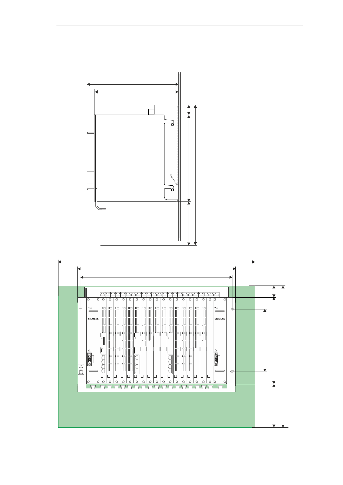
1.1.3 CM-2848 Basic Board Rack, 17 Slots
The basic board rack CM-2846 has 17 slots for modules and 2 slots for power supplies in
double euro format. It serves for the equipment of basic modules and peripheral modules.
It can be used for 19" (swing-)frame installation and rear panel assembly. This example
shows a board rack for the 19" (swing-)frame installation.
In section 1.2.2 Spa ce Requ irement you can find information on the dimensions.
Further information can be found in the SICAM AK 3 System Description.
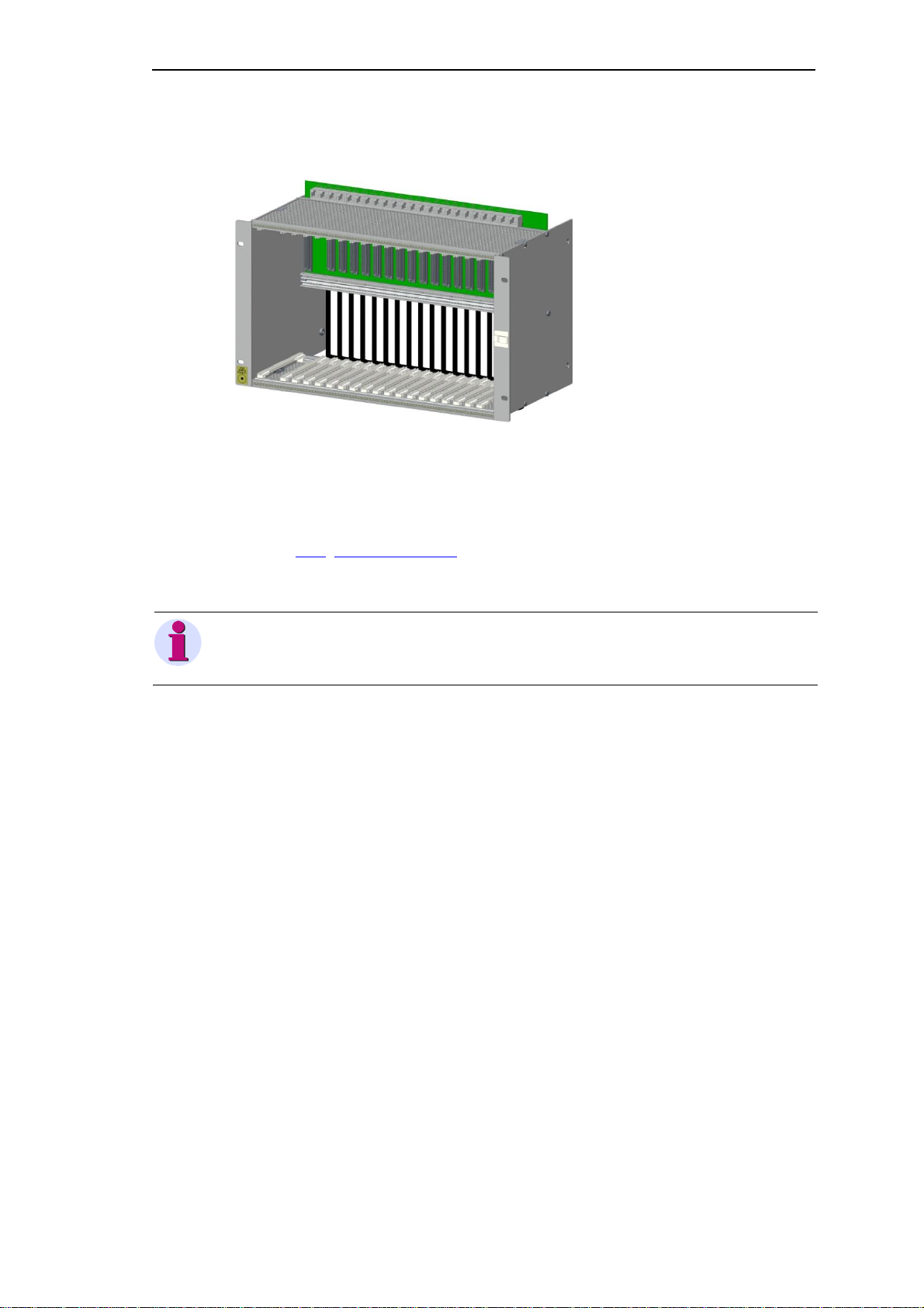
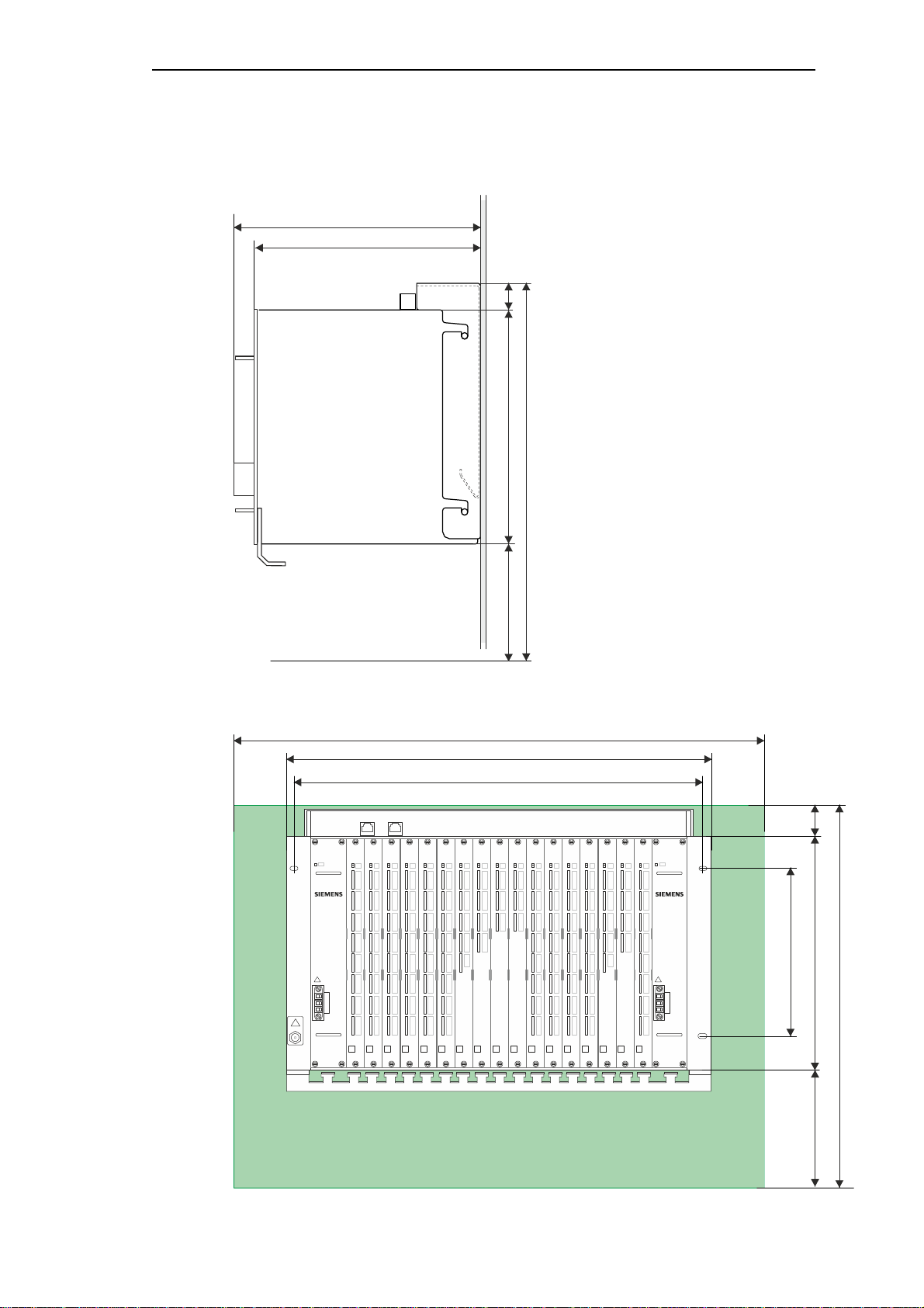
1.1.4 CM-2843 Expansion Board Rack, 16 Slots
The expansion board rack CM-2843 has 16 slots for modules and 2 slots for power supplies in
double euro format. It serves for the equipment of peripheral modules.
It can be used for 19" (swing-)frame installation and rear panel assembly. This example
shows a board rack for the 19" (swing-)frame installation.
In section 1.2.2, Space Requirement you can find information on the dimensions.
Further information can be found in the SICAM AK 3 System Description.
20 SICAM RTUs, SICAM AK 3 User Manu al
Edition 07.2016, DC2-02 8-2.03
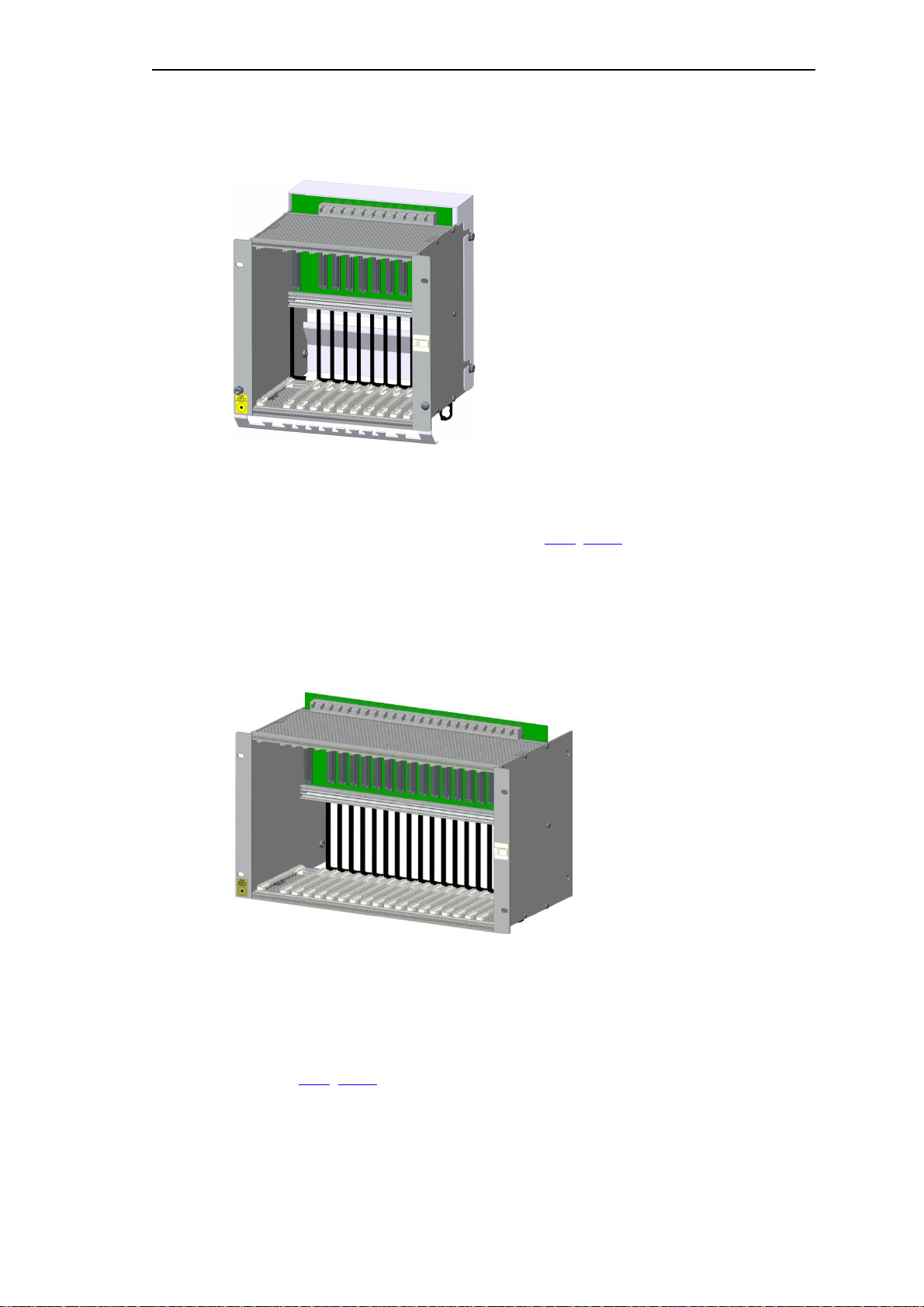
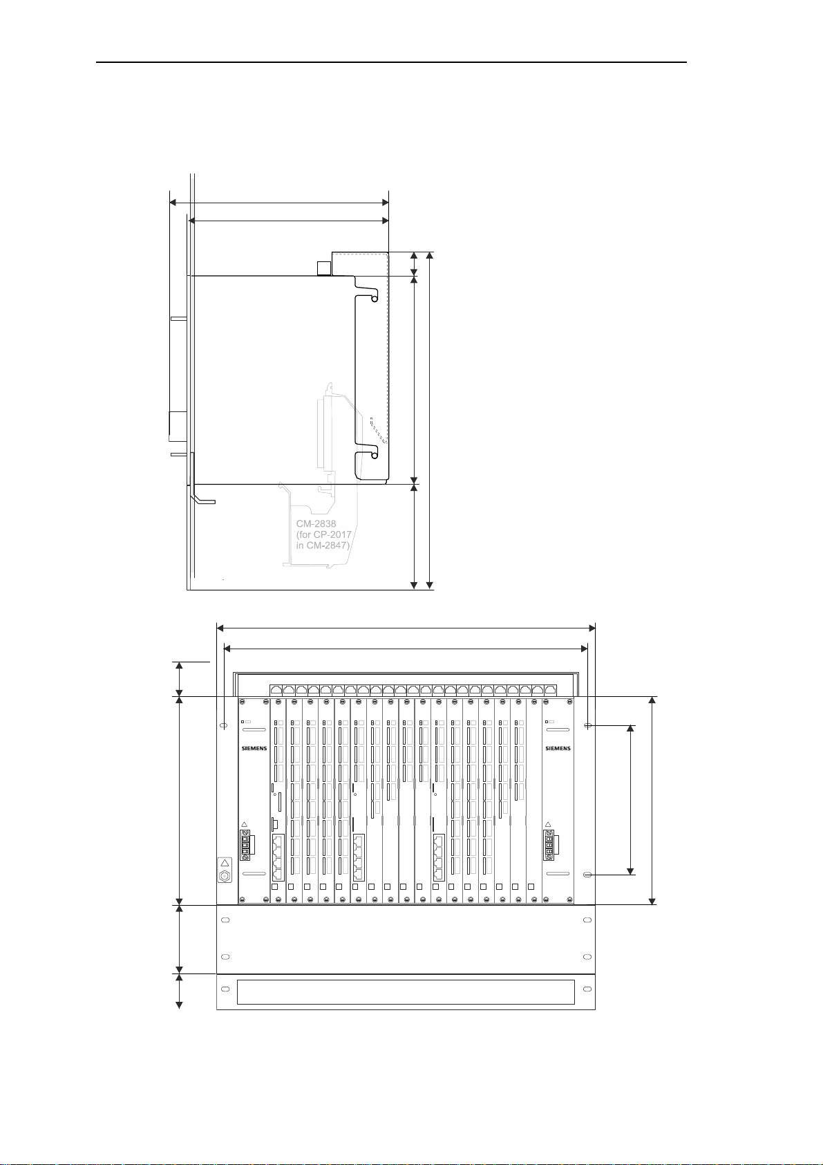
1.1.5 CM-2847 Migration Board Rack, 17 Slot
The migration board rack CM-2847 has 17 slots for modules and 2 slots for power supplies in
double-Europe format. It serves for the equipment of basic modules and peripheral modules.
Installation
The board rack is desig ned for 19“ (swing-) frame installation.
In section 1.2.2,Space Requirement you can find information on the dimensions.
Further information can be found in the SICAM AK 3 System Description.
Hint
This board rack was primarily designed for the combined use with the SICAM AK basic system element
CP-2017/PCCX25 in SICAM AK 3. It enables the installation of the connection board CM-2838, which is
required by the basic system element CP-2017/PCCX25.
SICAM RTUs, SICAM AK 3 User Manu al 21
DC2-028-2.03, Edition 07.2016

Installation
1.2 Board Rack Installation
1.2.1 Installation Location
The system SICAM AK 3 can be used for the installation in a cabinet.
Systems, which use a CM-2846 board rack, are primarily designed for the 19" (swing-) frame
installation, but can optionally be expanded for rear panel installation.
Systems, which use a CM-2844 board rack, are designed for the rear panel installation.
Note:
The syst em SI C AM AK 3 may on ly be installed hori z ontally.
1.2.2 Space Requirement
Certain minimum distances must be observed between board rack and adjacent equipment.
These minimum distances serve the installation and removal of components, the cabling and
the vent ilation of the devi ce in operation.
22 SICAM RTUs, SICAM AK 3 User Manu al
Edition 07.2016, DC2-02 8-2.03
1.2.2.1 CM-2844 - Rear Panel Installation
280
258
Space needed for cabling
Cabinet rear panel
AI-2301
PS-263x
295
415
3
5
282
minimum free space
30
266
Installation
430
PS-26 3x C P-2016 DI- 2110 DO-2210 AI-230 0 AI-2301CP-2019
SICAM AK
3HU
SICAM AK
266
190
435
3HU
SICAM RTUs, SICAM AK 3 User Manu al 23
DC2-028-2.03, Edition 07.2016

Installation
280
258
Space needed for cabling
Cabinet rear panel
PS-263x
DI-2110
DI-211 0
DI-2110
AI-2301
DO-22 10
483
603
3
5
465
1.2.2.2 CM-2846 - Rear Panel Installation
30
266
430
PS-263x
SICAM AK
3HU
DI-2110CP-2016 CP-2019 AI-23 01 AI- 2300DO-2210DI-2110 DI-211 0 DI-2 110 AI-2300
CP-2019
SICAM AK
266
190
435
24 SICAM RTUs, SICAM AK 3 User Manu al
minimum free space
3HU
Edition 07.2016, DC2-02 8-2.03
1.2.2.3 CM-2848 – Rear Panel Installation
280
258
Space needed for cabling
Cabinet rear panel
PS-263x
DI-2110
DI-211 0
DI-2110
AI-2301
DO-22 10
483
603
3
5
465
30
266
Installation
430
PS-263x
SICAM AK
DI-2110CP-2016 CP-2019 AI-23 01 AI- 2300DO-2210DI-2110 DI-211 0 DI-2 110 AI-2300
CP-2019
3HU
SICAM AK
266
190
435
minimum free space
3HU
SICAM RTUs, SICAM AK 3 User Manu al 25
DC2-028-2.03, Edition 07.2016
Installation
280
258
Space needed
Frame
SICAM AK
PS-26 3x
AI-23 00
DI-2110
DI-2110
DI-2110
CP-2019
AI-2301
DO-2210
483
465
6HU1HU2HU1H
U
1.2.2.4 CM-2846, CM-2847, CM-2848 - 19" (Swing-) Frame Installation
30
266
430
for cabling
PS-263x
SICAM AK
DI-211 0CP-2016 CP-2019 AI-2301 AI-2300DO-2210DI-2110 DI-2110 DI-2110
3HU
266
190
26 SICAM RTUs, SICAM AK 3 User Manu al
Edition 07.2016, DC2-02 8-2.03
1.2.2.5 CM-2843 - Rear Panel Installation
280
258
Cabinet rear panel
PS-263x
DI-2110
DI-211 0
DI-2110
AI-2301
DO-22 10
483
603
3
5
465
DI-21 10
30
266
Installation
430
Space needed for cabling
PS-263x
DI-2110CP-2016 CP-2019 AI- 2301 AI-2300DO-2210DI-2110 DI-211 0 DI -2110 AI-2300
DI-2110
SICAM AK
DI-2110
3HU
DI-2110
SICAM AK
266
190
435
minimum free space
SICAM RTUs, SICAM AK 3 User Manu al 27
DC2-028-2.03, Edition 07.2016
3HU
Installation
280
258
Frame
483
465
SICAM AK
PS-26 3x
AI-23 00
DI-2110
DI-2110
DI-2110
AI-2301
DO-2210
DI-2110
DI-211 0
6HU1HU2HU1H
U
1.2.2.6 CM-2843 - 19" (Swing-) Frame Installation
30
266
430
Space needed for cabling
PS-263x
DI-211 0CP-2016 CP-2019 AI-2301 AI-2300DO-2210DI-2110 DI-2110 DI-2110
DI-2110
SICAM AK
DI-2110
3HU
266
190
28 SICAM RTUs, SICAM AK 3 User Manu al
Edition 07.2016, DC2-02 8-2.03
Installation
CP-2019
AI-2301
DI-2110
DI-2110
DO-2210
AI-2300
CP-2019
AI-2301
SICAM AK
PS-263x
DI-2110
AI-2301
DI-2110
DI-2110
SICAM AK
AI-2301
DI-2110
DI-2110
DO-2210
AI-2300
SICAM AK
PS-263x
DI-2110
AI-2301
DI-2110
DI-2110
AI-2300
DI-2110
DI-2110
1.2.2.7 Examples for 19" (Swing-) Frame Installation of 2 Board Racks
3-6HU
1HU
6HU
PS-263x CP-2016 DI -2110 DO-2210 AI-23 00
SICAM AK
ESD
EARTH
FACILITY
DI-2110
2HU
1HU
6HU
2HU
1HU
PS-263x DI -2110 DO-2210 AI-2 300
DI-2110
DI-2110
SICAM RTUs, SICAM AK 3 User Manu al 29
DC2-028-2.03, Edition 07.2016
Installation
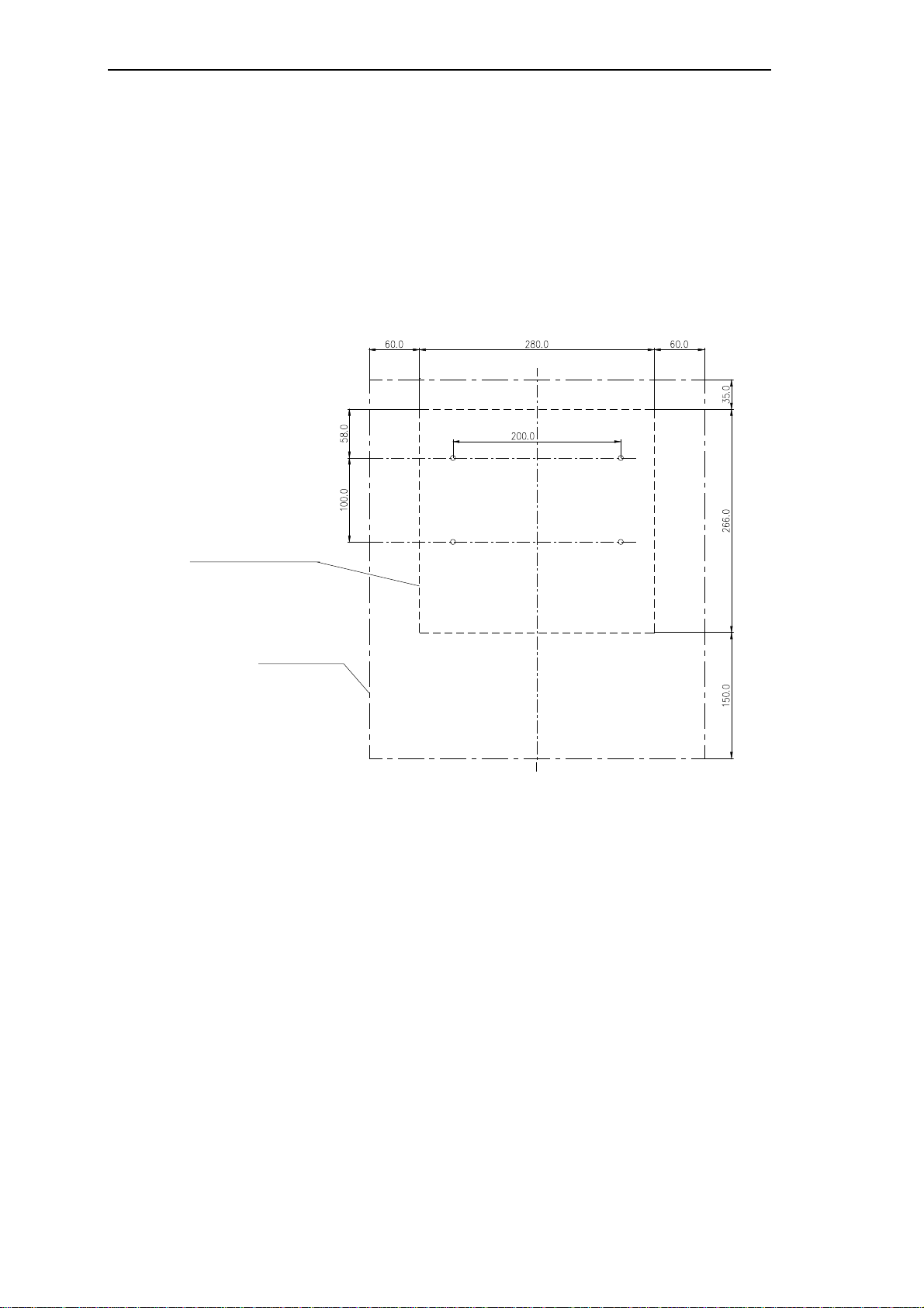
1.2.3 Install Board Rack CM-2844
The b oard rack CM-2844 is supplied as set w ith wall bracket and cabl e strain relief .
Proceed as follows:
• r emov e t he wal l br ack et fr om the boar d r ack
• Mark out the drill holes for the wall bracket on the rear panel of the cabinet according to
the enclosed drilling dia gram (DC2-000-1)
DEVICE EDGE WITHOUT
WALL BRACKET
MINIMUM SPACE
• Drill the holes according to the specifications on the drilling diagram
30 SICAM RTUs, SICAM AK 3 User Manu al
Edition 07.2016, DC2-02 8-2.03
 Loading...