

Page 1

SICAM P38 P39
Preface
Content
Overview 1
Technical Data 2
3-phase Power Meter with
Multi-Tariff function
V1.30
Manual
Functions 3
Operation and Display 4
Installation and Wiring 5
Communication 6
Maintenance 7
Ordering Number 8
E50417-H8940-C564-4
Page 2

NOTE
For your own safety, observe the warnings and safety instructions contained in this document, if available.
Disclaimer of Liability
This document has been subjected to rigorous technical review
before being published. It is revised at regular intervals, and any
modifications and amendments are included in the subsequent
issues. The content of this document has been compiled for
information purposes only. Although Siemens AG has made best
efforts to keep the document as precise and up-to-date as possible,
Siemens AG shall not assume any liability for defects and damage
which result through use of the information contained herein.
This content does not form part of a contract or of business
relations; nor does it change these. All obligations of Siemens AG
are stated in the relevant contractual agreements.
Siemens AG reserves the right to revise this document from time to
time.
Copyright
Copyright © Siemens AG 2015. All rights reserved.
The disclosure, duplication, distribution and editing of this
document, or utilization and communication of the content are not
permitted, unless authorized in writing. All rights, including rights
created by patent grant or registration of a utility model or a design,
are reserved.
Registered Trademarks
SIPROTEC®, DIGSI®, SIGUARD®, SIMEAS®, and SICAM® are
registered trademarks of Siemens AG. Any unauthorized use is
illegal. All other designations in this document can be trademarks
whose use by third parties for their own purposes can infringe the
rights of the owner.
Document Version: V01.10.01
Release date:
06.2018
Siemens Power Automation Ltd. Order No.: E50417-H8940-C564-4
Page 3

Preface
Purpose of this manual
This manual describes the functions, operation, installation, and commissioning of devices 3-phase Current
Power Meter-> In particular, one will find:
• Information regarding the configuration of the scope of the device and a description of the device functions
> Chapter 3
• Instructions for Operation and Display > Chapter 4
• Technical Data > Chapter 2
T arget Audience
Protection engineers, commissioning engineers, personnel concerned with adjustment, checking, and service
of selective protective equipment, automatic and control facilities, and personnel of electrical facilities and
power plants.
Additional Support
Should further information on the System SICAM be desired or should particular problems arise which are not
covered sufficiently for the purchaser's purpose, the matter should be referred to the local Siemens representative.
Our Customer Support Center provides a 24-hour service.
Phone: +49 (180) 524-7000
Fax: +49 (180) 524-2471
E-mail: [email protected]
Notes on Safety
This document is not a complete index of all safety measures required for operation of the equipment
(module or device). However, it comprises important information that must be followed for personal safety, as
well as to avoid material damage. Information is highlighted and illustrated as follows according to the degree
of danger:
DANGER
DANGER means that death or severe injury will result if the measures specified are not taken.
✧ Comply with all instructions, in order to avoid death or severe injuries.
WARNING
WARNING means that death or severe injury may result if the measures specified are not taken.
✧ Comply with all instructions, in order to avoid death or severe injuries.
SICAM P38 P39, 3-phase Power Meter with Multi-Tariff function, User Manual
E50417-H8940-C564-4, Release Date 06.2018
3
Page 4
Preface
CAUTION
CAUTION means that medium-severe or slight injuries can occur if the specified measures are not taken.
✧ Comply with all instructions, in order to avoid moderate or minor injuries.
NOTICE
NOTICE means that property damage can result if the measures specified are not taken.
✧ Comply with all instructions, in order to avoid property damage.
NOTE
Important information about the product, product handling or a certain section of the documentation which
must be given particular attention.
Qualified Electrical Engineering Personnel
Only qualified electrical engineering personnel may commission and operate the equipment (module, device)
described in this document. Qualified electrical engineering personnel in the sense of this manual are people
who can demonstrate technical qualifications as electrical technicians. These persons may commission,
isolate, ground and label devices, systems and circuits according to the standards of safety engineering.
Proper Use
The equipment (device, module) may be used only for such applications as set out in the catalogs and the
technical description, and only in combination with third-party equipment recommended and approved by
Siemens.
Problem-free and safe operation of the product depends on the following:
• Proper transport
• Proper storage, setup and installation
• Proper operation and maintenance
When electrical equipment is operated, hazardous voltages are inevitably present in certain parts. If proper
action is not taken, death, severe injury or property damage can result:
• The equipment must be grounded at the grounding terminal before any connections are made.
• All circuit components connected to the power supply may be subject to dangerous voltage.
• Hazardous voltages may be present in equipment even after the supply voltage has been disconnected
(capacitors can still be charged).
• Operation of equipment with exposed current-transformer circuits is prohibited. Before disconnecting the
equipment, ensure that the current-transformer circuits are short-circuited.
• The limiting values stated in the document must not be exceeded. This must also be considered during
testing and commissioning.
■
4
SICAM P38 P39, 3-phase Power Meter with Multi-Tariff function, User Manual
E50417-H8940-C564-4, Release Date 06.2018
Page 5

Contents
1 Overview . . . . . . . . . . . . . . . . . . . . . . . . . . . . . . . . . . . . . . . . . . . . . . . . . . . . . . . . . . . . . . . . . . . . . . . . . . . . . . . . .7
1.1 Introduction . . . . . . . . . . . . . . . . . . . . . . . . . . . . . . . . . . . . . . . . . . . . . . . . . . . . . . . . . . . . . . . . . . . . . . .8
1.2 Features . . . . . . . . . . . . . . . . . . . . . . . . . . . . . . . . . . . . . . . . . . . . . . . . . . . . . . . . . . . . . . . . . . . . . . . . 8
2 Technical Data . . . . . . . . . . . . . . . . . . . . . . . . . . . . . . . . . . . . . . . . . . . . . . . . . . . . . . . . . . . . . . . . . . . . . . . . . . . .9
2.1 Technical Data . . . . . . . . . . . . . . . . . . . . . . . . . . . . . . . . . . . . . . . . . . . . . . . . . . . . . . . . . . . . . . . . . . .10
3 Functions . . . . . . . . . . . . . . . . . . . . . . . . . . . . . . . . . . . . . . . . . . . . . . . . . . . . . . . . . . . . . . . . . . . . . . . . . . . . . . .13
3.1 Parameter Measurement. . . . . . . . . . . . . . . . . . . . . . . . . . . . . . . . . . . . . . . . . . . . . . . . . . . . . . . . . . . .14
3.2 Power Metering . . . . . . . . . . . . . . . . . . . . . . . . . . . . . . . . . . . . . . . . . . . . . . . . . . . . . . . . . . . . . . . . . . .15
3.3 Demand Measurement . . . . . . . . . . . . . . . . . . . . . . . . . . . . . . . . . . . . . . . . . . . . . . . . . . . . . . . . . . . . .16
3.4 Settlement . . . . . . . . . . . . . . . . . . . . . . . . . . . . . . . . . . . . . . . . . . . . . . . . . . . . . . . . . . . . . . . . . . . . . . .17
3.5 Time Division . . . . . . . . . . . . . . . . . . . . . . . . . . . . . . . . . . . . . . . . . . . . . . . . . . . . . . . . . . . . . . . . . . . . .17
3.6 Event Record . . . . . . . . . . . . . . . . . . . . . . . . . . . . . . . . . . . . . . . . . . . . . . . . . . . . . . . . . . . . . . . . . . . . .18
3.7 Freezing. . . . . . . . . . . . . . . . . . . . . . . . . . . . . . . . . . . . . . . . . . . . . . . . . . . . . . . . . . . . . . . . . . . . . . . . .18
3.8 Limit violation Alarm. . . . . . . . . . . . . . . . . . . . . . . . . . . . . . . . . . . . . . . . . . . . . . . . . . . . . . . . . . . . . . . .19
3.9 Display and Buttons . . . . . . . . . . . . . . . . . . . . . . . . . . . . . . . . . . . . . . . . . . . . . . . . . . . . . . . . . . . . . . .20
3.10 Communication . . . . . . . . . . . . . . . . . . . . . . . . . . . . . . . . . . . . . . . . . . . . . . . . . . . . . . . . . . . . . . . . . . .20
3.11 Permission and Security Management . . . . . . . . . . . . . . . . . . . . . . . . . . . . . . . . . . . . . . . . . . . . . . . . .20
3.12 Digital Input and Output Interface . . . . . . . . . . . . . . . . . . . . . . . . . . . . . . . . . . . . . . . . . . . . . . . . . . . . .21
4 Operation and Display . . . . . . . . . . . . . . . . . . . . . . . . . . . . . . . . . . . . . . . . . . . . . . . . . . . . . . . . . . . . . . . . . . . . .23
4.1 Full-screen Display . . . . . . . . . . . . . . . . . . . . . . . . . . . . . . . . . . . . . . . . . . . . . . . . . . . . . . . . . . . . . . . 24
4.2 Cyclic Display . . . . . . . . . . . . . . . . . . . . . . . . . . . . . . . . . . . . . . . . . . . . . . . . . . . . . . . . . . . . . . . . . . . .24
4.3 Key Definition. . . . . . . . . . . . . . . . . . . . . . . . . . . . . . . . . . . . . . . . . . . . . . . . . . . . . . . . . . . . . . . . . . . . .26
5 Installation and Wiring . . . . . . . . . . . . . . . . . . . . . . . . . . . . . . . . . . . . . . . . . . . . . . . . . . . . . . . . . . . . . . . . . . . .37
5.1 Total Dimension . . . . . . . . . . . . . . . . . . . . . . . . . . . . . . . . . . . . . . . . . . . . . . . . . . . . . . . . . . . . . . . . . . 38
5.2 Precautions of Installation . . . . . . . . . . . . . . . . . . . . . . . . . . . . . . . . . . . . . . . . . . . . . . . . . . . . . . . . . . .38
5.3 Terminals and Wiring Diagram. . . . . . . . . . . . . . . . . . . . . . . . . . . . . . . . . . . . . . . . . . . . . . . . . . . . . . . .39
6 Communication . . . . . . . . . . . . . . . . . . . . . . . . . . . . . . . . . . . . . . . . . . . . . . . . . . . . . . . . . . . . . . . . . . . . . . . . . .43
6.1 Use of Communication . . . . . . . . . . . . . . . . . . . . . . . . . . . . . . . . . . . . . . . . . . . . . . . . . . . . . . . . . . . . .44
6.2 Introduction of MODBUS-RTU Communication Protocol . . . . . . . . . . . . . . . . . . . . . . . . . . . . . . . . . . .45
6.2.1 Overview . . . . . . . . . . . . . . . . . . . . . . . . . . . . . . . . . . . . . . . . . . . . . . . . . . . . . . . . . . . . . . . . . . . . .45
6.2.2 Function of Application Layer. . . . . . . . . . . . . . . . . . . . . . . . . . . . . . . . . . . . . . . . . . . . . . . . . . . . . .46
6.2.3 CRC Method . . . . . . . . . . . . . . . . . . . . . . . . . . . . . . . . . . . . . . . . . . . . . . . . . . . . . . . . . . . . . . . . . .47
6.2.4 Information mapping table . . . . . . . . . . . . . . . . . . . . . . . . . . . . . . . . . . . . . . . . . . . . . . . . . . . . . . . .48
SICAM P38 P39, 3-phase Power Meter with Multi-Tariff function, User Manual
E50417-H8940-C564-4, Release Date 06.2018
5
Page 6

Contents
7 Maintenance . . . . . . . . . . . . . . . . . . . . . . . . . . . . . . . . . . . . . . . . . . . . . . . . . . . . . . . . . . . . . . . . . . . . . . . . . . . .67
7.1 Maintenance . . . . . . . . . . . . . . . . . . . . . . . . . . . . . . . . . . . . . . . . . . . . . . . . . . . . . . . . . . . . . . . . . . . . . 68
8 Ordering Number . . . . . . . . . . . . . . . . . . . . . . . . . . . . . . . . . . . . . . . . . . . . . . . . . . . . . . . . . . . . . . . . . . . . . . . .69
8.1 Ordering Number . . . . . . . . . . . . . . . . . . . . . . . . . . . . . . . . . . . . . . . . . . . . . . . . . . . . . . . . . . . . . . . . . 70
6
SICAM P38 P39, 3-phase Power Meter with Multi-Tariff function, User Manual
E50417-H8940-C564-4, Release Date 06.2018
Page 7

Overview 1
1.1 Introduction 8
1.2 Features 8
SICAM P38 P39, 3-phase Power Meter with Multi-Tariff function, User Manual
E50417-H8940-C564-4, Release Date 06.2018
7
Page 8

Overview
1.1 Introduction
1.1 Introduction
SICAM P38 & P39 3-phase Multi-function Power Meter integrate measurement, record, power metering,
remote communication and control, large screen LCD and network communication functions. This meter can
measure various parameters of power grid, such as voltage, current, power, power factor and frequency. It is
provided with 2
active and reactive energy. It has multi-tariff energy and multi-tariff demand functions. P38 has two independent
RS-485 ports; P39 has 1 RS-485 & 1 Ethernet port. Device supports MODBUS-RTU protocol (serial & TCP/IP).
Besides, it has binary input and output.
This product is extensively applicable to power substation and distribution automation system, industrial control
and industrial automation system, energy management system and community power monitoring, etc.
This 3-phase electronic multi-function power meter meets following standards:
• IEC 62052-11:2003 (Electricity metering equipment (a.c.) General requirements, tests and test conditionsPart 11: Metering equipment) standard
• IEC 62053-22:2003 static meters for active energy (classes 0.2 S and 0.5 S)
• IEC 62053-23:2003 static meters for reactive energy (classes 2 and 3)
• Modbus-RTU
nd
to 50th harmonic analysis and calculation of multiple power quality parameters. It can calculate
1.2 Features
This meter uses high-precision sampling and metering unit and high-speed MCU data processing unit, supporting high-precision, wide-range and accurate measurement and quick data analysis; segmented multi-line WVA
LCD, realizing various and abundant display; white backlight for LCD, satisfying the need for viewing data in
dark environment; NVRAM, supporting long-time data storage without data loss even in the event of power failure; high-precision clock chip with temperature compensation, ensuring accuracy of clock within operating temperature range; double communication ports and industrial standard communication protocols, realizing flexible
and convenient networking; and different communication modules, satisfying different interface need of different users.
■
8
SICAM P38 P39, 3-phase Power Meter with Multi-Tariff function, User Manual
E50417-H8940-C564-4, Release Date 06.2018
Page 9

Technical Data 2
2.1 Technical Data 10
SICAM P38 P39, 3-phase Power Meter with Multi-Tariff function, User Manual
E50417-H8940-C564-4, Release Date 06.2018
9
Page 10
Technical Data
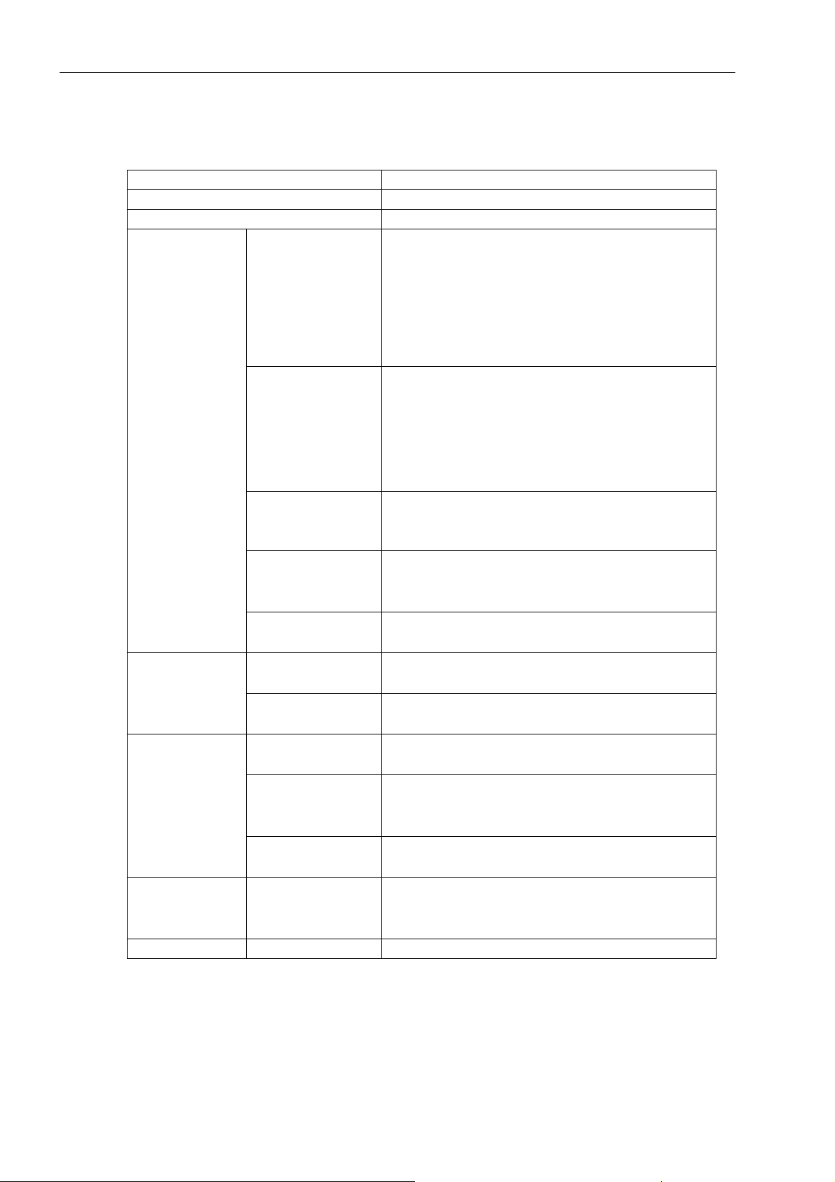
2.1 Technical Data
2.1 Technical Data
Item Technical Data
Product standard IEC61557-12:2007
Input connection 3-phase-3-wire, 3-phase-4-wire, single phase
Voltage
Measurement
Metering
Digital signal
Communication
Environment Operating temp. -25 ℃ ... +60 ℃
Current
Power
(active, reactive, apparent)
Power grid frequency
Harmonic
Active power
Reactive power
Power pulse output
Binary output
Binary input
RS-485 port
Reference voltage U
AC57.7 V
: AC380 V, AC220 V, AC100 V,
n
Measuring range: 10 V ... 276 V phase voltage
Maximum measuring range: 400 V phase voltage
Power consumption: < 0.1 VA (single phase @220VAC)
Accuracy: RMS 0.2%
Resolution: 0.01 V
Rated current I
: 1 A, 5 A
n
Measuring range: 0.015 A ... 6 A
Maximum measuring range: 9 A
Power consumption: < 0.3 VA (single phase @5A)
Accuracy: RMS 0.2%
Resolution: 0.001 A
Accuracy: 0.5%
Resolution: 0.001 kW/kVar/kVA
Measuring range: 45 Hz ... 65 Hz
Accuracy: 0.2%
Resolution: 0.01 Hz
nd
th
Frequency: 2
... 50
Precision: 5%
Accuracy level: 0.5 S, Acc. To IEC 62053-22
Resolution: 0.01 kWh, 5000 imp/kWh
Accuracy level: Class 2, Acc. To IEC 62053-23
Resolution: 0.01 kvarh, 5000 imp/kvarh
2 electric energy (active and reactive) pulse outputs
Opto-coupler isolation, 4,000 V
RMS
2 electromagnetic relay output
Normal Open Contact
Contact capacity: AC 250 V /3 A, DC 30 V /3 A
4 dry contact inputs
Opto-coupler isolation, 4,000 V
RMS
Interface type: Twisted Pair, Half Duplex Transmission
Communication rate: 600 bps ... 38,400 bps
Protocol: Modbus-RTU
10
SICAM P38 P39, 3-phase Power Meter with Multi-Tariff function, User Manual
E50417-H8940-C564-4, Release Date 06.2018
Page 11

■
Others
Item Technical Data
Operating temp. limit -35 ℃ ... +70 ℃
Relative humidity ≤ 95% (condensation free)
Clock < 0.5 sec./day (-40 ℃ .... +85 ℃ )
AC or DC power supply
Operating power
supply
Max. input range: 40 V ... 420 V
Power consumption: ≤ 2 W, 4 VA
Total dimension (mm): 96×96×95
Dimension
Panel cut out size (mm): 92×92
IP53
Weight Approx. 450 g
Technical Data
2.1 Technical Data
SICAM P38 P39, 3-phase Power Meter with Multi-Tariff function, User Manual
E50417-H8940-C564-4, Release Date 06.2018
11
Page 12

Technical Data
2.1 Technical Data
12
SICAM P38 P39, 3-phase Power Meter with Multi-Tariff function, User Manual
E50417-H8940-C564-4, Release Date 06.2018
Page 13

Functions 3
3.1 Parameter Measurement 14
3.2 Power Metering 15
3.3 Demand Measurement 16
3.4 Settlement 17
3.5 Time Division 17
3.6 Event Record 18
3.7 Freezing 18
3.8 Limit violation Alarm 19
3.9 Display and Buttons 20
3.10 Communication 20
3.11 Permission and Security Management 20
3.12 Digital Input and Output Interface 21
SICAM P38 P39, 3-phase Power Meter with Multi-Tariff function, User Manual
E50417-H8940-C564-4, Release Date 06.2018
13
Page 14
Functions
3.1 Parameter Measurement
3.1 Parameter Measurement
This meter is provided with various measuring functions. Power grid parameters and index measurable are as
follows:
• Voltage of each phase and mean voltage
• Voltage of each line and mean voltage
• Current of each phase, average current and neutral current
• Total and separate active power, reactive power and apparent power of each phase
• Phase angle of voltage and current of each phase
• Total and separate power factor of each phase
• Power grid frequency and measuring range 45 Hz to 65 Hz
nd
• Effective value and ratio of 2
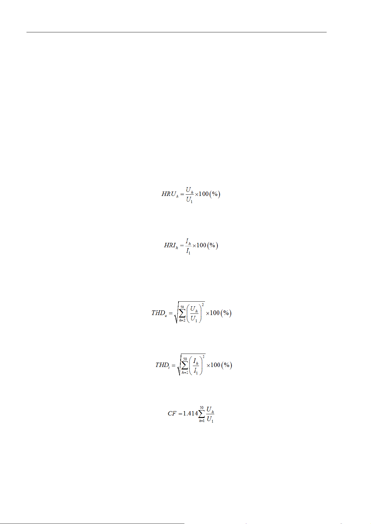
- Harmonic voltage ratio:
to 50th harmonic voltage and harmonic current of each phase
where, Uh - No. h harmonic voltage (RMS); U1 - fundamental voltage (RMS).
- Harmonic current ratio:
where, I
- No. h harmonic current (RMS); I1 - fundamental current (RMS).
h
• Total harmonic voltage distortion and total harmonic current distortion of each phase
- Total harmonic voltage distortion:
- Total harmonic current distortion:
• Voltage wave crest factor (CF) of each phase, indicating peak of distorted waveform
14
SICAM P38 P39, 3-phase Power Meter with Multi-Tariff function, User Manual
E50417-H8940-C564-4, Release Date 06.2018
Page 15
Functions
3.2 Power Metering
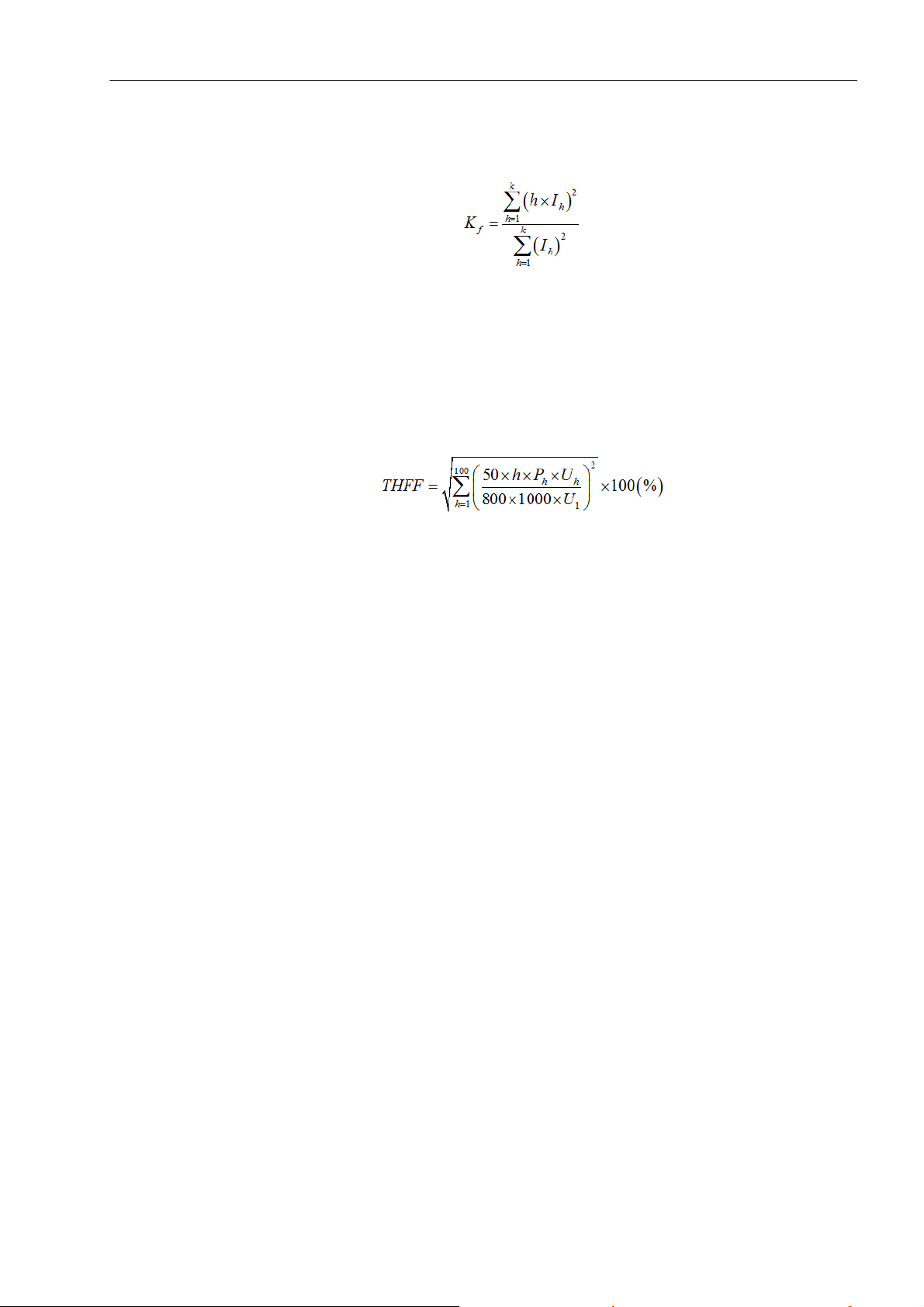
• Current K coefficient K
of each phase, a critical index measuring current quality
f
where, I
- effective value of No. h harmonic current (RMS); k - range 1 to 50, configurable with communi-
h
cation, factory default 50.
• Telephone harmonic form factor (THFF) of each phase
Harmonic interference will generate communication system noise, reducing quality of connection. Consul-
tative Committee of International Telephone and Telegraph (CCITT) measures harmonic interference to
telecommunication using weight coefficient Ph of noise, expressed with THFF.
where, P
- weight coefficient of noise.
h
3.2 Power Metering
This meter can meter various energy:
• Combined active and supply and demand active energy
• Combined reactive and four-quadrant reactive energy
• Fundamental active power and total harmonic active energy
• Import and export active energy of each phase, combined reactive energy of each phase, fundamental active
energy and harmonic active energy
SICAM P38 P39, 3-phase Power Meter with Multi-Tariff function, User Manual
E50417-H8940-C564-4, Release Date 06.2018
15
Page 16

Functions
3.3 Demand Measurement
3.3 Demand Measurement
1. Terms and Definitions
Demand means average power within specified period. The maximum value of demand recorded within
specified period is maximum demand.
Current demand means average current within specified period. The maximum current value recorded within
specified period is called maximum current demand.
Demand cycle means continuous equal intervals for measuring average power.
Sliding window time means time interval for measuring maximum demand through recursion. It is less than
demand interval.
Temporary unit means the memory unit of the meter, used for temporary storage of power value or current
value when calculating maximum demand.
Demand interval can be selected from 5, 10, 15, 30 and 60 min. Sliding window time can be selected from
1, 2, 3 and 5 min. Demand interval is five times the sliding window time and is 60 at maximum.
2. In the event of power-on, zero clearing, clock adjustment and interval change of voltage line, the meter will
execute demand measurement depending on demand interval from current moment. When the first demand
interval is completed, maximum demand will be recorded at slip interval. Maximum demand will not be recorded within an incomplete demand interval.
3. When power direction changes, temporary demand unit will be cleared. Temporary demand unit will not be
cleared when across rate period to ensure continuity of maximum demand measurement. Zero clearing of
temporary unit is necessary when:
• Overall clearing of meter;
• Clearing maximum demand upon communication command;
• Clearing maximum demand manually through button;
• Change of power direction;
• Settlement among different months.
4. This meter is capable of various maximum demand calculation functions, including import/export active
demand and occurrence time, combined reactive and four-quadrant reactive maximum demand and occurrence time, import/export apparent demand, maximum current demand of Phase A, Phase B and Phase C
and occurrence time.
5. Combined reactive maximum demand means the quadrant with maximum demand value among reactive
quadrant participating in combined computation. For example, value of reactive combined status character
2 is 05 H. Typical combined reactive 1 = 1st quadrant reactive + 2nd quadrant reactive. Assuming reactive
maximum demand of 1
st
quadrant in a demand interval is 100kvar and the same of 2nd quadrant is 200 kvar,
maximum demand value of combined reactive demand 1 within the same demand interval will be 200 kvar.
6. This meter is provided with two types of zero clearing for demand: clearing via communication and manual
clearing with button. For description of the latter, see subsequent content.
7. For time generating maximum demand, minute synchronization or clock synchronization is available. This is
controlled by parameter mode character 2. For mode character 2, see the table below. Such mode supports
parameter setting and alteration through communication.
Bit Function Bit Value vs Function Default
Bit 7 Reserved 0
Bit 6 Reserved 0
Bit 5 Demand synchronization mode
1: minute synchronization 0: clock syn-
chronization
1
Bit 4 Extreme value settlement 1: daily 0: monthly 0
Bit 3 Reserved 0
Bit 2 Reserved 0
16
SICAM P38 P39, 3-phase Power Meter with Multi-Tariff function, User Manual
E50417-H8940-C564-4, Release Date 06.2018
Page 17

Bit Function Bit Value vs Function Default
Bit 1 Reserved 0
Bit 0 Reserved 0
3.4 Settlement
1. Settlement means the meter can save current electric energy and demand data at the settlement time preset.
It is also called cross month settlement.
2. Settlement day (automatic reading day) can be set through communication and any time within the 1
day can be set.
3. When crossing settlement day in case of power failure, cross month settlement will be applied depending on
number of months crossed. But, when more than 3 months, data of only 3 months will be settled.
4. The meter can save historical settlement data of previous 12 months. Historical settlement data include
electric energy data and demand data.
Functions
3.4 Settlement
st
to 28th
3.5 Time Division
1. The meter has a built-in high-precision real-time clock backed up by battery, carrying calendar and
supporting automatic switching for leap year.
2. 6 tariffs, 14 periods, 8 daily periods, 14 yearly time zones and 100 public holidays can be set maximally and
weekend period can be set. If tariff number of certain period is over number of tariffs (error), default tariff (tariff
1) will be used.
3. Electric energy and maximum demand data recorded by the meter include 6 tariffs, but time-shared data will
not be recorded for each phase (A, B and C).
SICAM P38 P39, 3-phase Power Meter with Multi-Tariff function, User Manual
E50417-H8940-C564-4, Release Date 06.2018
17
Page 18

Functions
3.6 Event Record
3.6 Event Record
1. Instantaneous extreme value of power grid will be recorded. The meter can record maximum value and
minimum value of each phase voltage, line voltage, phase current, neutral current, active power, reactive
power and apparent power within cycle time. Cycle time can be "month" or "day" and is set through
parameter mode character 2. At most extreme values of three cycles can be saved.
2. Zero clearing, demand clearing and event clearing can be recorded. The meter records 10 latest zero clearing events.
3. Power failure event can be recorded. The meter records 10 latest power failure events, containing start time
and end time of power failure.
4. Timing event can be recorded. The meter records 10 latest timing events, containing pre-timing time and
post-timing time.
5. Voltage and current unbalance event can be recorded. The meter records 10 latest voltage unbalance events
and 10 latest current unbalance events. Decision limit and decision delay time of voltage and current unbalance events are set by parameter.
Voltage unbalance ratio = (3-phase voltage maximum difference / 3-phase voltage mean) x 100%, where 3-
phase voltage maximum difference is the largest difference between effective values of each phase voltage
(only Uab and Ubc for 3-phase-3-wire) and 3-phase voltage mean is the mean of effective values of 3-phase
voltage.
Current unbalance ratio = (3-phase current maximum difference / 3-phase current mean) x 100%, where 3-
phase current maximum difference is the largest difference between effective values of each phase current
(only Iab and Ibc for 3-phase-3-wire) and 3-phase current mean is the mean of effective values of 3-phase
current.
6. Statistic data of voltage eligibility rate can be recorded. The meter records statistic voltage eligibility of each
phase within recent 12 months. Upper and lower limits for voltage assessment are set by parameter. Statistic
data of voltage eligibility include voltage monitoring time, voltage limit violation time, voltage eligibility and
voltage limit violation rate.
7. Relay closing event can be recorded. The meter has 2 relay outputs. When manual control is set for relay,
the meter will record 10 latest manual closing records of relay output. Closing time and status will be recorded.
8. SOE event can be recorded. The meter can record SOE events of 4 digital binary inputs and save 50 latest
records. Time of switch motion (exact to 1 msec), shift status and switch port number are recorded.
3.7 Freezing
1. Cyclic freezing: The meter can save data of 72 latest cyclic freezing actions. Start time and interval of freezing
are set with parameter. The content is import/export total active energy.
2. Daily freezing: The meter can save data of 8 latest daily freezing actions, including total active energy, total
reactive energy, four-quadrant reactive energy and total active maximum demand.
18
SICAM P38 P39, 3-phase Power Meter with Multi-Tariff function, User Manual
E50417-H8940-C564-4, Release Date 06.2018
Page 19

3.8 Limit violation Alarm
1. This product is provided with limit violation alarm function. User may select from voltage, current, power,
power factor and frequency parameters at most 6 data groups at the same time as detection object and set
upper and lower limits and judgment condition for them. Alarm will be activated when measured value is over
the set limit. This product is provided with 2 relay outputs. When alarm parameters are configured that output
is made from certain relay which is at automatic mode (not manual), limit violation alarm signal can be output
through such relay.
2. At most 6 limit violation alarm parameters can be set at the same time within the product. Configuration flow
of each limit violation alarm parameter: select type of detected data-set threshold of detected data-set
judgment condition-select output relay for alarm signal.
• Code of various detected data: (hexadecimal number for Modbus-RTU code)
MODBUS code Content of data MODBUS code Content of data
00 Phase A power factor 14 Phase A active power
01 Phase B power factor 15 Phase B active power
02 Phase C power factor 16 Phase C active power
03 Total power factor 17 Total active power
06 Frequency 18 Phase A reactive power
07 Phase A voltage 19 Phase B reactive power
08 Phase B voltage 1A Phase C reactive power
09 Phase C voltage 1B Total reactive power
0B Uab line voltage 1C Phase A apparent power
0C Ubc line voltage 1D Phase B apparent power
0D Uca line voltage 1E Phase C apparent power
0F Phase A current 1F Total phase apparent power
10 Phase B current 20 Active demand
11 Phase C current 21 Reactive demand
12 Neutral current 22 Apparent demand
Functions
3.8 Limit violation Alarm
When code of detected data is FF, limit violation alarm function of such group is off.
• Threshold of detected data: threshold judging whether detected value is limit violation; Different units for
different data types: such as voltage-V, current-A, active-KW, reactive power-KVAR, apparent-KVA,
frequency-Hz.
• Judging condition: 0 means alarm activated when exceeding limit; 1 means alarm activated when falling
below limit.
• Alarm signal output relay: 0 means no alarm signal output; 1 means alarm signal outputted from relay 1;
2 means alarm signal outputted from relay 2; 3 means alarm signal outputted from relay 1 and relay 2 at
the same time.
3. Example of alarm parameter setting. Set one limit violation alarm parameter to automatic detection and alarm
for "Phase A voltage", assuming that alarm threshold is 240 V, judging criterion is "over limit” and signal is
outputted from relay 2.
Use MODBUS RTU protocol to set alarm parameter: set 0110 address to "07", 0111 to "0000", 0112 to "5DC0"
(multiply "240" by 100 to generate "24,000" and convert it into "00005DC0"), 0113 to "00" and 0114 to "02".
SICAM P38 P39, 3-phase Power Meter with Multi-Tariff function, User Manual
E50417-H8940-C564-4, Release Date 06.2018
19
Page 20

Functions
3.9 Display and Buttons
3.9 Display and Buttons
This product uses large-screen WVA multi-line LCD to provide visual and various display. The screen is
provided with white backlight, enabling clear display in dark environment. Specific data information can be
obtained through display with button operation. For details, see Chapter Operation and Display.
3.10 Communication
RS485 port is provided for parameter setting and reading of various data. Two independent RS485
communication ports are default configuration.
3.11 Permission and Security Management
1. This product is provided with programming permission management function.
• L0 password: used for meter reset, setting all parameters and modifying L0, L2 and L4 passwords;
• L2 password: used for meter reset, setting all parameters and modifying L2 and L4 passwords;
• L4 password: used for parameter setting, demand clearing and modifying L4 password, not for meter reset,
event clearing, clearing extreme values and PT/CT ratio setting.
• All level default PASSWORD is "000000"
2. Parameter setting is available only when this product is in programmable state. Steps for entering
programming state: press " " and " " at the same time to enter "PASS" screen; input correct
password and press " " to enter "SET" screen and enable programmable state. After entering
programmable state, programmable state prompt appears on the bottom right corner of LCD. Programmable
state will remain valid in 10 minutes after program button is pressed and become invalid after power down.
3. If incorrect password is used to set this product continuously (including communication setting and button
programming) up to specific number of times (factory default 5 times), parameter setting function will be
locked (factory default 60 minutes). Error count will be reset after setting once using correct password if such
count is less than specific limit. Error count of password and lock time can be set (available in factory state).
4. Broadcast timing is available only once each day and time for adjustment is no more than 5 min.
20
SICAM P38 P39, 3-phase Power Meter with Multi-Tariff function, User Manual
E50417-H8940-C564-4, Release Date 06.2018
Page 21
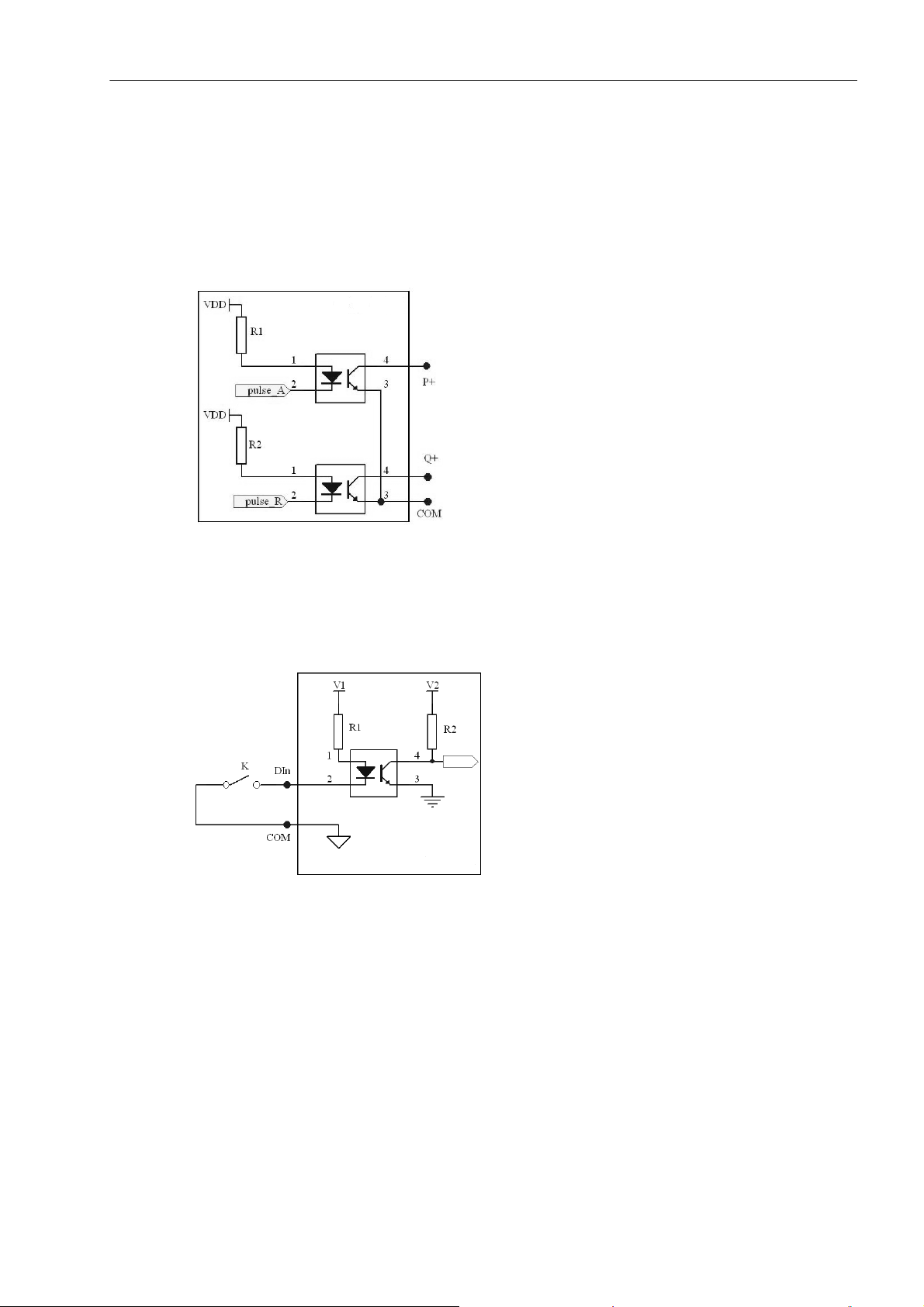
3.12 Digital Input and Output Interface
Power Pulse Output
This meter provides two power pulse outputs: active and reactive, with internal opto-isolation, pulse output
width (80±20) ms, maximum allowable passing current 10 mA (DC) and operating voltage range 5 V to 80 V
(DC).
Functions
3.12 Digital Input and Output Interface
Figure 3-1 Circuit Diagram of Power Pulse Output Interface
Binary Input Interface
This product is provided with 4-digit binary inputs interface based on passive dry contact. Terminals are identified as DI1, DI2, DI3, DI4 and COM. COM is the common terminal.
Figure 3-2 Circuit Diagram of Binary Input Interface
SICAM P38 P39, 3-phase Power Meter with Multi-Tariff function, User Manual
E50417-H8940-C564-4, Release Date 06.2018
21
Page 22
Functions
3.12 Digital Input and Output Interface
Relay Output Interface
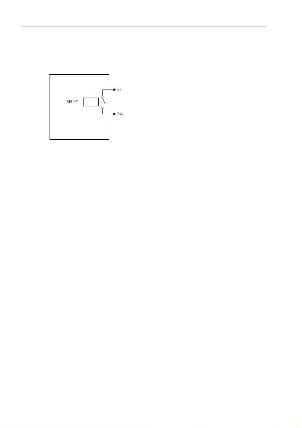
This product is provided with two relay outputs interfaces for alarm indication or protection control output in
many conditions. Electric parameter of internal relay: AC 250 V/DC 30 V, 3 A.
Figure 3-3 Circuit Diagram of Relay Output Interface
■
22
SICAM P38 P39, 3-phase Power Meter with Multi-Tariff function, User Manual
E50417-H8940-C564-4, Release Date 06.2018
Page 23

Operation and Display 4
4.1 Full-screen Display 24
4.2 Cyclic Display 24
4.3 Key Definition 26
SICAM P38 P39, 3-phase Power Meter with Multi-Tariff function, User Manual
E50417-H8940-C564-4, Release Date 06.2018
23
Page 24
Operation and Display
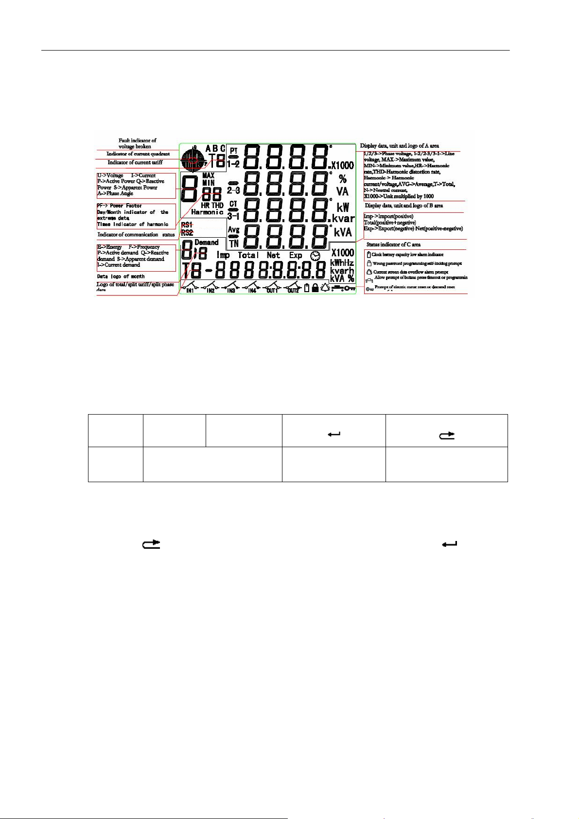
4.1 Full-screen Display
4.1 Full-screen Display
Figure 4-1 Description of LCD Indication
4.2 Cyclic Display
Key Functions at Cyclic Display Mode
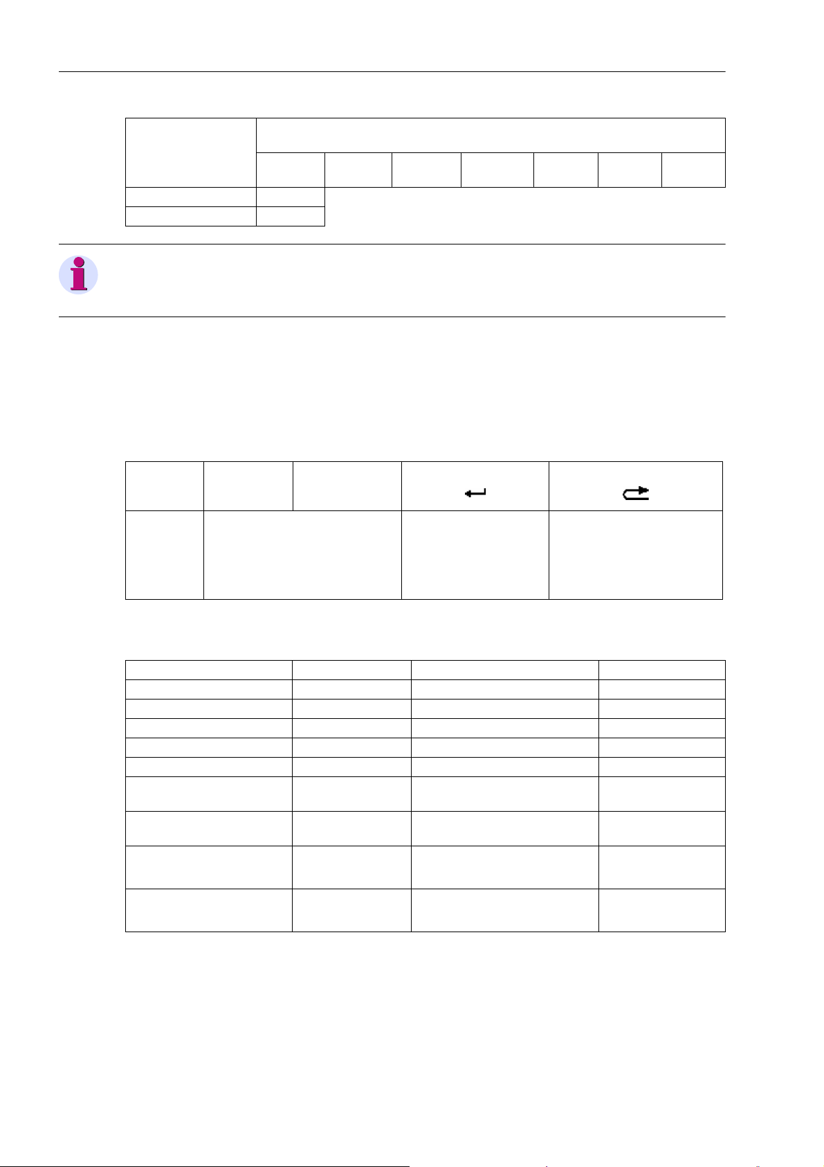
Key symbol ▲▼
Function
Screen Lock in Cyclic Display State
Data in display area A or B can be locked in cyclic display state to enable long-time monitoring of data in certain
area.
Steps: press " ", select the desired display area (target data will blink thrice), and press " " to lock, and
vice versa for unlocking.
Cyclic Display Parameter
Duration: 1 to 99 sec., configurable;
Number of items: to be defined with one byte. 4 high 4 bits are number of items in display area A while 4 low 4
bits are number of items in display area B. 16 items are acceptable to each area. At any time, display area A
and display area B should have at least one cyclic display item.
Switching from cyclic display to
buttom display
Lock/unlock blinking
display
Switching between display
areas A and B (blinking
prompt)
Cyclic Display State
Cyclic display data in areas A and B can be defined by user. User may develop cyclic display scheme previously
through inquiring "Code list of optional settings in areas A and B".
24
SICAM P38 P39, 3-phase Power Meter with Multi-Tariff function, User Manual
E50417-H8940-C564-4, Release Date 06.2018
Page 25
Operation and Display
4.2 Cyclic Display
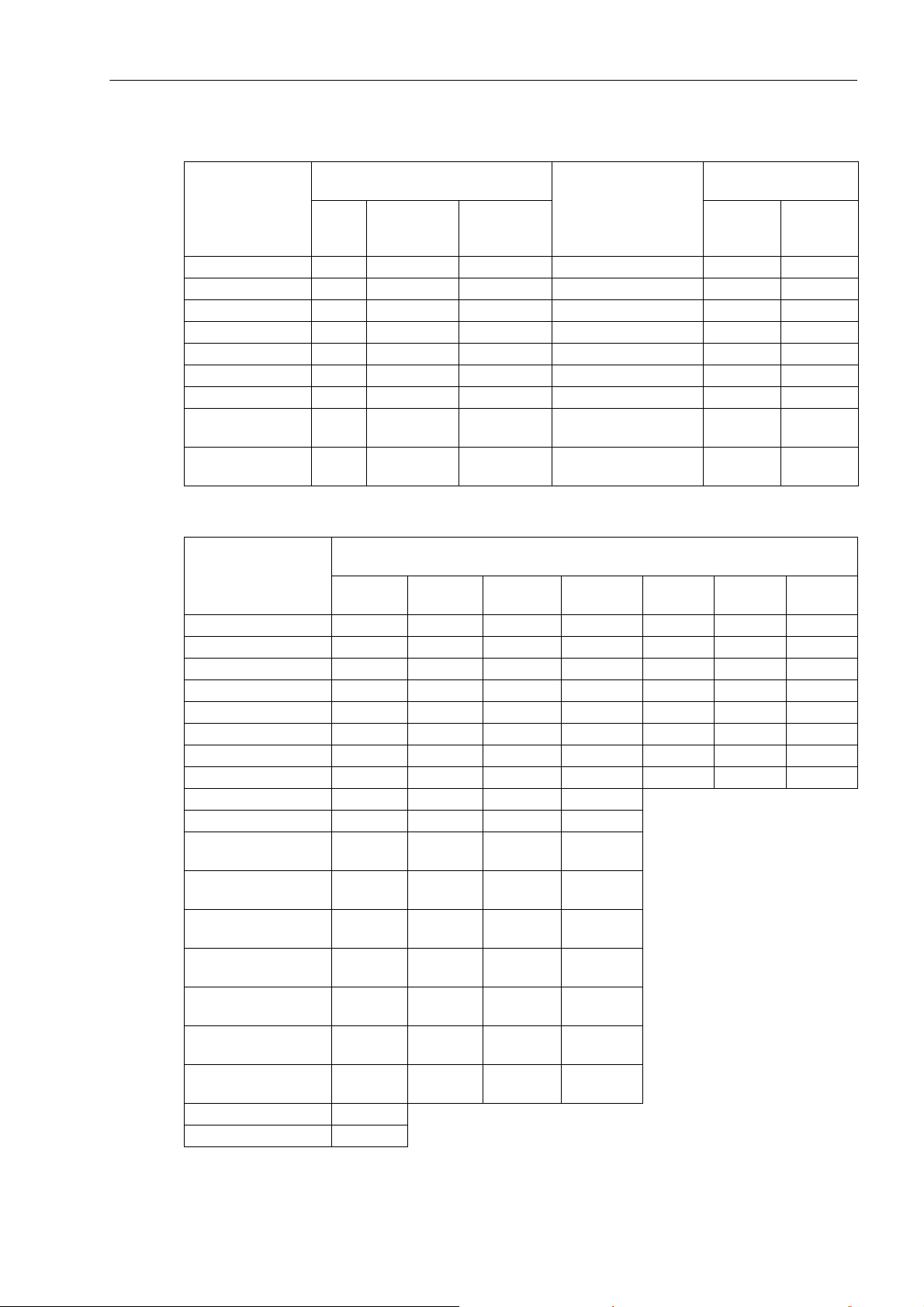
Code list of optional settings in area A:
Data item Data type (current value) Data item Data type (current
value)
Transient
Maximun
(previous 1
to 3 months)
Minimum
(previous 1
to 3 months)
Transient 2
nd
to 50
Phase voltage 0 1 (2 ... 4) 5 (6 ... 8) Voltage unbalance rate 66 /
Line voltage 9 10 (11 ... 13) 14 (15 ... 17) Current unbalance rate 67 /
Current 18 19 (20 ... 22) 23 (24 ... 26) Voltage eligibility rate 68 /
Neutral current 27 28 (29 ... 31) V Voltage distortion rate 69 /
Active power 36 37 (38 ... 40) 41 (42 ... 44) Current distortion rate 70 /
Reactive power 45 46 (47 ... 49) 50 (51 ... 53) Fundamental voltage 71 72 ... 120
Apparent power 54 55 (56 ... 58) 59 (60 ... 62) Fundamental current 121 120 ... 170
Power factor 63 / / Second harmonic
171 172 ... 219
voltage ratio
Phase angle 64 / / Second harmonic
220 221 ... 268
current ratio
Code list of optional settings in area B:
th
Data: 7 continuous co des express tot al, t ariff 1 to t ariff 6 in order; 4 continuous
Data item
codes express current month, previous 1 to 3 months in order.
Current
Previous
1 month
Previous 2
month
Previous 3
month
Phase A Phase B Phase C
Import active power 351 ... 357 358 ... 364 365 ... 371 372 ... 378 379 ... 382 383 ... 386 387 ... 390
Export active power 391 ... 397 398 ... 404 405 ... 411 412 ... 418 419 ... 422 423 ... 426 427 ... 430
Total active power 431 ... 437 438 ... 444 445 ... 451 452 ... 458 459 ... 462 463 ... 466 467 ... 470
Net active power 471 ... 477 478 ... 484 485 ... 491 492 ... 498 499 ... 502 503 ... 506 507 ... 510
Import reactive power 511 ... 517 518 ... 524 525 ... 531 532 ... 538 539 ... 542 543 ... 546 547 ... 550
Export reactive power 551 ... 557 558 ... 564 565 ... 571 572 ... 578 579 ... 582 583 ... 586 587 ... 590
Total reactive power 591 ... 597 598 ... 604 605 ... 611 612 ... 618 619 ... 622 623 ... 626 627 ... 630
Net reactive power 631 ... 637 638 ... 644 645 ... 651 652 ... 658 659 ... 662 663 ... 666 667 ... 670
Import active demand 671 ... 677 678 ... 684 685 ... 691 692 ... 698
Export active demand 699 ... 705 706 ... 712 713 ... 719 720 ... 726
Import reactive
demand
Export reactive
demand
Import apparent
demand
Export apparent
demand
Phase A forward
current demand
Phase B forward
current demand
Phase C forward
current demand
727 ... 733 734 ... 740 741 ... 747 748 ... 754
755 ... 761 762 ... 768 769 ... 775 776 ... 782
783 ... 789 790 ... 796 797 ... 803 804 ... 810
811 ... 817 818 ... 824 825 ... 831 832 ... 838
839 ... 845 846 ... 852 853 ... 859 860 ... 866
867 ... 873 874 ... 880 881 ... 887 888 ... 894
895 ... 901 902 ... 908 909 ... 915 916 ... 922
Frequency 923
Data 924
SICAM P38 P39, 3-phase Power Meter with Multi-Tariff function, User Manual
E50417-H8940-C564-4, Release Date 06.2018
25
Page 26
Operation and Display
4.3 Key Definition
Data: 7 continuous codes express total, tariff 1 to t ariff 6 in order; 4 continuous
Data item
codes express current month, previous 1 to 3 months in order.
Current
Time 250
Error code 926
Note
In flip-with-key state or parameter-set-with-key state, this product will automatically return to cyclic display state
if no key operation within defined duration.
4.3 Key Definition
Key Functions at Flip-With-Key Display Mode
Previous
1 month
Previous 2
month
Previous 3
month
Phase A Phase B Phase C
Key symbol ▲▼
Function
Data Item of Key Display
• Data items displayed in area A (mainly measuring data)
Level 1 Level 2 Level 1 Level 2
Voltage Extreme value Voltage unbalance rate /
Line voltage Extreme value Current unbalance rate /
Current Extreme value Voltage eligibility rate /
Active power Extreme value Voltage distortion rate /
Reactive power Extreme value Current distortion rate /
Apparent power Extreme value Fundamental voltage
Power factor / Fundamental current
Phase angle /
PT and CT ratio /
1) Switch from cyclic display state
to key display state through pressing "▲" or "▼".
2) Flip over to previous screen with
"▲" and to next screen with "▼".
Enter next menu
Second harmonic voltage
ratio
Second harmonic current
ratio
1) Switch between A and B
display areas (symbol of se-
lected area will flicker)
2) Return to previous menu
nd
2
to 50th harmonic
voltage
nd
to 50th harmonic
2
current
3rd to 50th
rd
3
to 50th
26
SICAM P38 P39, 3-phase Power Meter with Multi-Tariff function, User Manual
E50417-H8940-C564-4, Release Date 06.2018
Page 27
Operation and Display
4.3 Key Definition
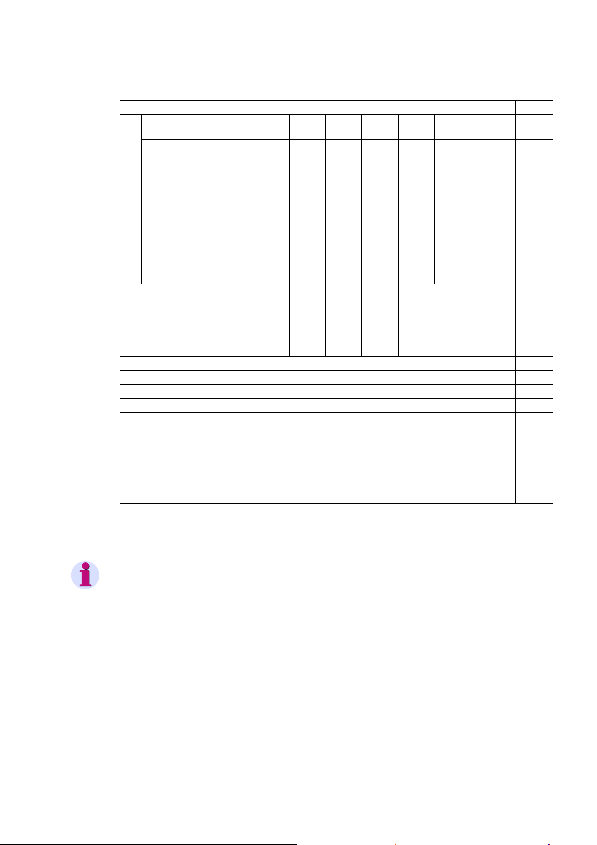
• Data items displayed in area B (mainly measuring data)
Level 1 Level 2 Level 3
Import
active
Total (01) (05) (09) (13) (17) (21) (25) (29)
Electric energy
Export
active
To ta l
active
Net
active
Import
reactive
Export
reactive
Tot a l r e -
active
Net re-
active
Previous
1 to 3
months
0 to 6
Ta ri ff
Previous
Phase A (02) (06) (10) (14) (18) (22) (26) (30)
1 to 3
months
Previous
Phase B (03) (07) (11) (15) (19) (23) (27) (31)
1 to 3
months
Previous
Phase C (04) (08) (12) (16) (20) (24) (28) (32)
1 to 3
months
Maximum
demend
Import
active
Export
active
Import
reactive
Export
reactive
Import
appar-
(33) (34) (35) (36) (37) (38) (39 ... 41)
ent
Export
appar-
ent
Current A/B/C
Previous
1 to 3
months
0 to 6
Ta ri ff
Frequency (42) //
Data (43) //
Time (44) //
Fault code (45) //
Active
constant
Reactive
Version
number
(46)
constant
Modbus
/
communi-
cation
address
• Data items combined in area A and B:
Firmware version number, active constant, reactive constant, Modbus communication address, etc.
Note
Full screen, firmware version number is displayed in order when the meter is power on.
SICAM P38 P39, 3-phase Power Meter with Multi-Tariff function, User Manual
E50417-H8940-C564-4, Release Date 06.2018
27
Page 28
Operation and Display
4.3 Key Definition
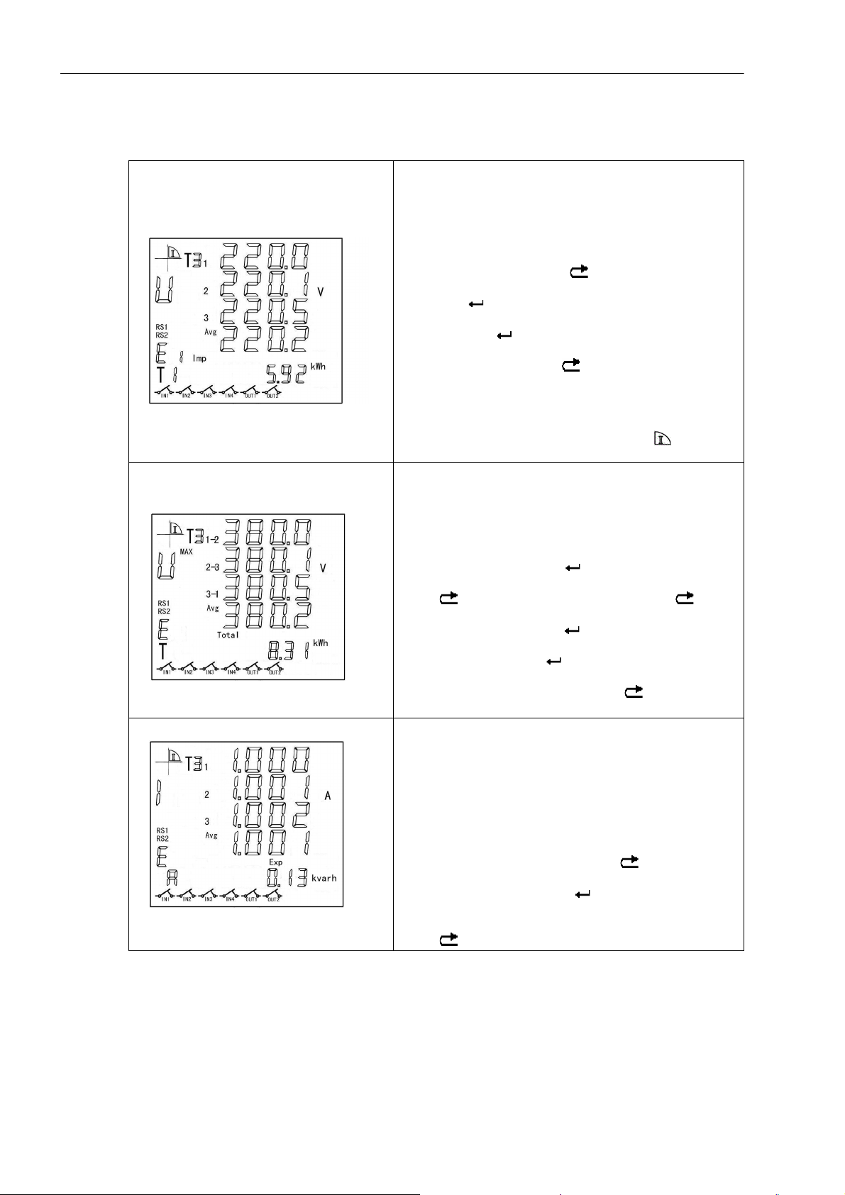
Examples for Flip-With-Key Operation
Example 1:
This screen shows A display area (phase voltage) and B
display area (electric energy at import active tariff on previous
settlement day).
At cyclic display mode, press "▲" or "▼" to enter key display
mode. When area A is selected, press "▲" or "▼" again to
switch to voltage items. Press “ ” to switch to area B. Press
"▲" or "▼" to switch to current import active total energy display. Press “ ” to enter second level display. Press "▲" or
"▼" to switch to import active total energy on previous settlement day. Press “ ” again to enter third level display. Press
"▲" or "▼" to view import active energy at each tariff on previous settlement day. Press “ ” to return to previous display.
"RS1" and “RS2” show there are two RS485 ports and flicker-
ing symbol means communication in progress. "T3" on upper
left corner means current operating tariff and " " means the
meter runs in first quartile.
Example 2:
This screen shows A display area (upper limit of current line
voltage) and B display area (current total active energy).
At cyclic display mode, press "▲" or "▼" to enter key display
mode. When area A is selected, press "▲" or "▼" to switch to
line voltage option and press " " to enter upper limit display.
You can also press "▲" or "▼" to view other extreme values.
Press " " to return to previous display. Press " " again
to switch to area B. Press "▲" or "▼" to switch to current total
active energy display. Press " " to enter second level display. Press "▲" or "▼" to view total active energy on previous
3 settlement days. Press " " again to enter third level display. Press "▲" or "▼" to view import active energy at each
tariff on previous settlement day. Press " " to return to previous display.
Example 3:
This screen shows A display area (phase current) and B
display area (current phase A total export reactive energy).
At cyclic display mode, press "▲" or "▼" to enter key display
mode. When area A is selected, press "▲" or "▼" again to
switch to current option.
In the figure, L1=1.000 A, L2=1.001 A, L3=1.002 A and 3phase average current=1.001 A. Press " " to switch to area
B. Press "▲" or "▼" to switch to current phase A total export
energy display. Press " " to enter second level dis-
ctive
rea
play. Press "▲" or "▼" to view phase A total export reactive
energy from previous 1 settlement day to 3 settlement days.
Press " " to return to previous display.
28
SICAM P38 P39, 3-phase Power Meter with Multi-Tariff function, User Manual
E50417-H8940-C564-4, Release Date 06.2018
Page 29
Operation and Display
4.3 Key Definition
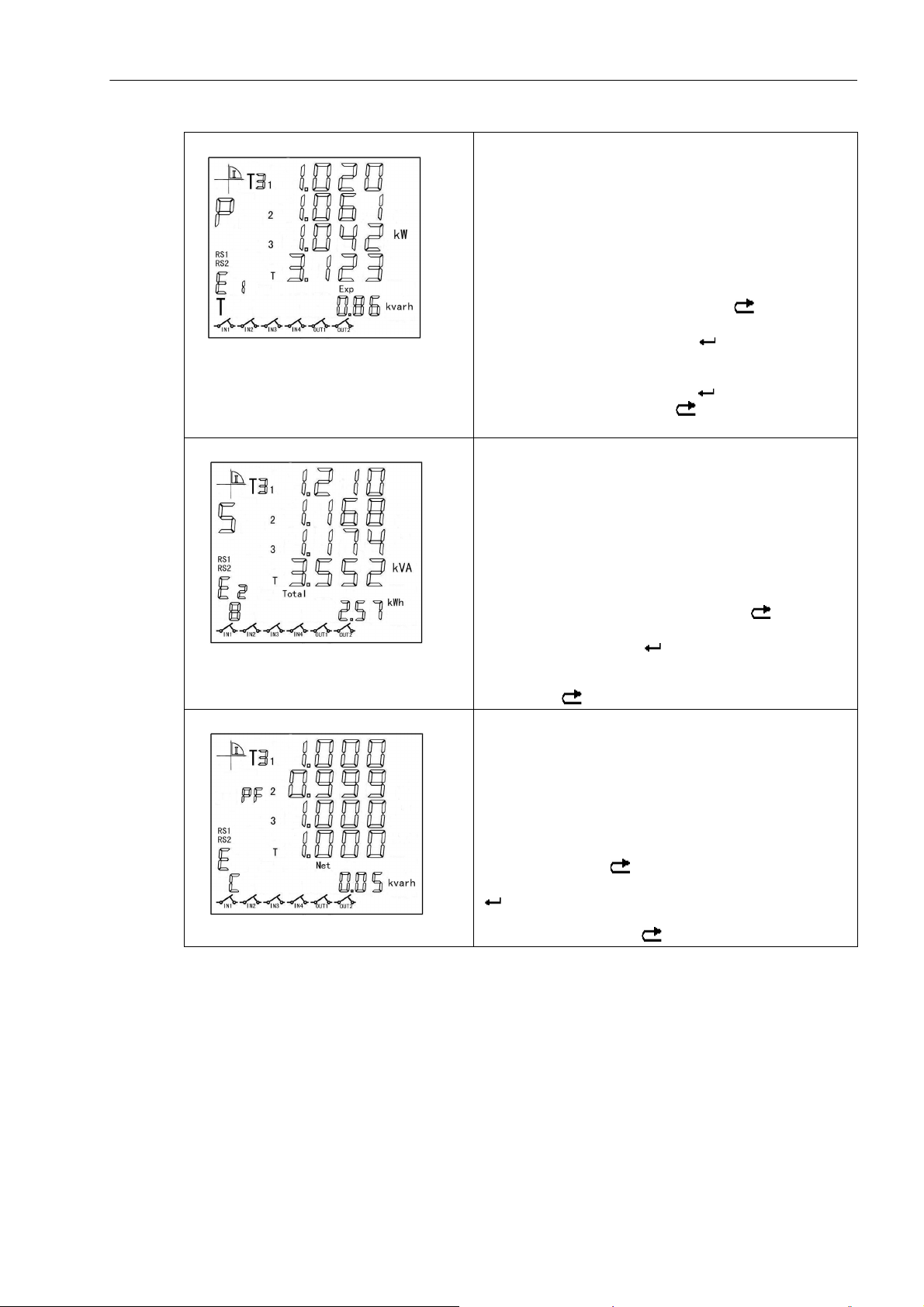
Example 4:
This screen shows A display area (current active power) and
B display area (total export reactive energy on previous settlement day).
At cyclic display mode, press "▲" or "▼" to enter key display
mode. When area A is selected, press "▲" or "▼" to enter
active power items.
In the figure of A, L1=1.020 kW, L2=1.061 kW, L3=1.042 kW
and total active power=3.123 kW. Press " " to switch to
area B. Press "▲" or "▼" to switch to total current export re-
active energy display. Then, press " " to enter total export
reactive energy on previous settlement day. You can press
"▲" or "▼" to view total export reactive energy from current to
previous 3 settlement days. Press " " to view export reactive energy at each tariff. Press " " to return to previous display.
Example 5:
This screen shows A display area (current apparent power)
and B display area (total active energy on previous 2 settlement days at phase B).
At cyclic display mode, press "▲" or "▼" to enter key display
mode. When area A is selected, press "▲" or "▼" to enter apparent power items.
In the figure of A, L1=1.210 kW, L2=1.168 kVA, L3=1.174 kVA
and total apparent power=3.552 kVA.Press " " to switch to
area B. Press "▲" or "▼" to switch to total current active
energy of phase B. Press " " to enter total active energy of
phase B on previous settlement day. You can press "▲" or "▼"
to view total active energy from previous 1 to 3 settlement
days. Press " " to return to previous display.
Example 6:
This screen shows A display area (current power factor) and
B display area (current net reactive energy of phase C).
At cyclic display mode, press "▲" or "▼" to enter key display
mode. When area A is selected, press "▲" or "▼" to switch to
power factor items.
In the figure, L1=1.000, L2=0.999, L3=1.000 and total power
factor=1.000. Press " " to switch to area B. Press "▲" or
"▼" to switch to current phase C net reactive energy. Press
" " to enter second level display. Press "▲" or "▼" to view
phase C net reactive energy from previous 1 settlement day to
3 settlement days. Press " " to return to previous display.
SICAM P38 P39, 3-phase Power Meter with Multi-Tariff function, User Manual
E50417-H8940-C564-4, Release Date 06.2018
29
Page 30
Operation and Display
4.3 Key Definition
Example 7:
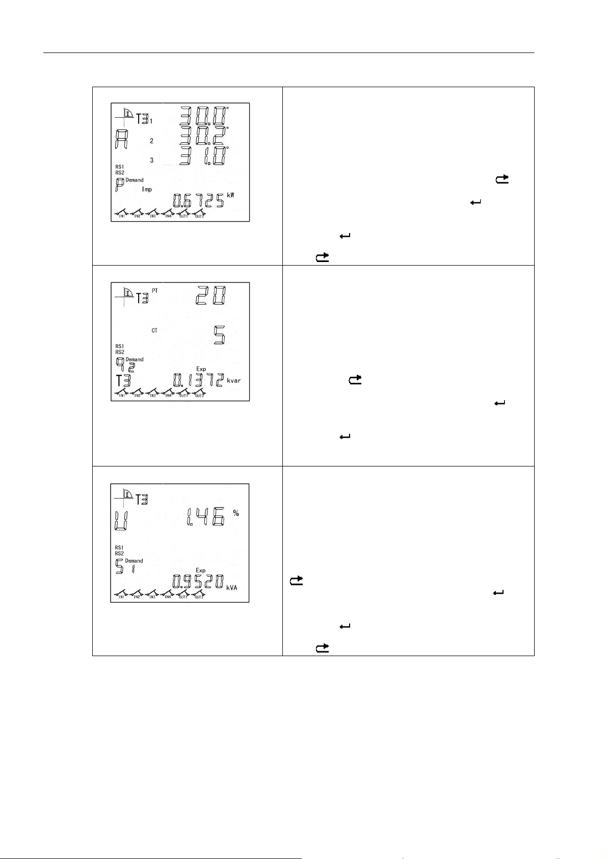
This screen shows A display area (phase angle) and B display
area (current total maximum import active demand).
At cyclic display mode, press "▲" or "▼" to enter key display
mode. When area A is selected, press "▲" or "▼" again to
switch to phase angle items.
In the figure, L1=30.0°, L2=30.2°, L3=31.0°. Press " "
again to switch to area B. Press "▲" or "▼" to switch to current
total maximum import active demand. Press " " to enter
second level display. Press "▲" or "▼" to view total maximum
import active demand from current to previous 3 settlement
days. Press " " again to enter third level display. Press "▲"
or "▼" to view maximum import active demand at each tariff.
Press " " to return to previous display.
Example 8:
This screen shows A display area (PT and CT conversion
ratio) and B display area (maximum export reactive demand
at tariff 3 of previous 2 settlement days/combined reactive 2).
At cyclic display mode, press "▲" or "▼" to enter key display
mode. When area A is selected, press "▲" or "▼" to enter PT
and CT ratio display items.
In the figure of A, PT conversion ratio=20.0, CT conversion ratio=5.0. Press " " to switch to area B. Press "▲" or "▼" to
switch to maximum export reactive demand at tariff 3 of previous 2 settlement days/combined reactive 2. Press " " to
enter second level display. Press "▲" or "▼" to switch to total
maximum export reactive demand on previous 2 settlement
days. Press " " again to enter third level display. Press "▲"
or "▼" to view maximum reactive demand at each tariff on previous 2 settlement days.
Example 9:
This screen shows A display area (current voltage unbalance
rate) and B display area (total maximum export apparent
demand on previous settlement day).
At cyclic display mode, press "▲" or "▼" to enter key display
mode. When area A is selected, press "▲" or "▼" switch to
current voltage unbalance rate option.
30
In the figure of A, voltage unbalance rate = 1.46%. Press
" " to switch to area B. Press "▲" or "▼" to switch to total
maximum export apparent demand display. Press " " to
enter second level display. Press "▲" or "▼" to view total
maximum export apparent demand on previous 3 settlement
days. Press " " again to enter third level display. Press "▲"
or "▼" to vi
Press " "
SICAM P38 P39, 3-phase Power Meter with Multi-Tariff function, User Manual
ew maximum export reactive demand at each tariff.
to return to previous display.
E50417-H8940-C564-4, Release Date 06.2018
Page 31
Operation and Display
4.3 Key Definition
Example 10:
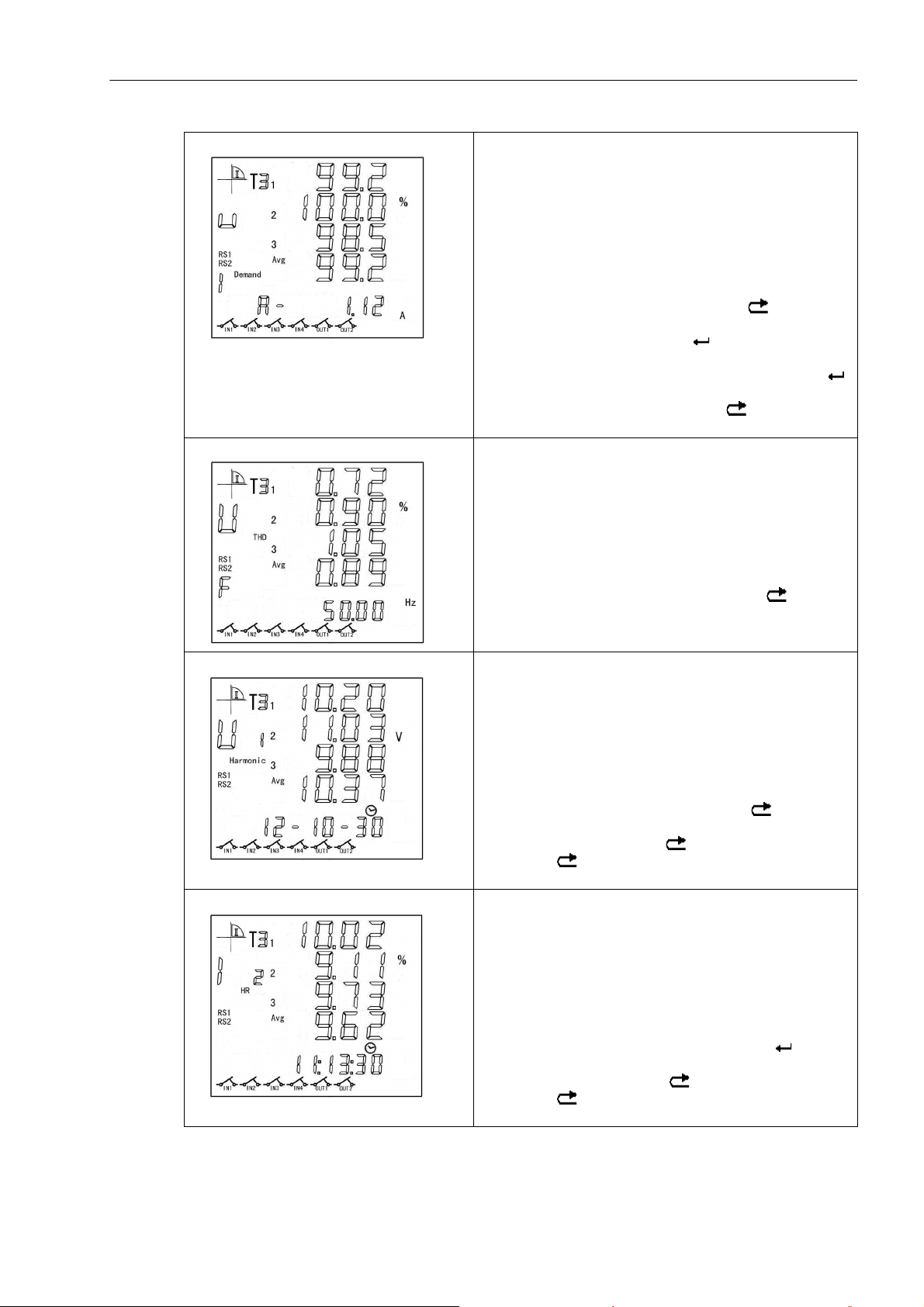
This screen shows A display area (current voltage eligibility
rate) and B display area (current phase A current maximum
demand).
At cyclic display mode, press "▲" or "▼" to enter key display
mode. When area A is selected, press "▲" or "▼" to enter
voltage eligibility rate option.
In the figure of A, L1=99.2%, L2=100.0%, L3=98.5% and
mean voltage eligibility rate=99.2%. Press " " to switch to
area B. Press "▲" or "▼" to switch to current phase A current
maximum demand display. Press " " to enter second level
display. Press "▲" or "▼" to view current phase A current
maximum demand on previous 3 settlement days. Press " "
again to enter third level display. Press "▲" or "▼" to view
maximum demand at each tariff. Press " " to return to previous display.
Example 11:
This screen shows A display area (voltage distortion rate) and
B display area (frequency).
At cyclic display mode, press "▲" or "▼" to enter key display
mode. When area A is selected, press "▲" or "▼" again to
switch to voltage distortion rate option.
In the figure of A, L1=0.72%, L2=0.90%, L3=1.05% and
average voltage distortion rate=0.89%. Press " " to return
to area B and press "▲" or "▼" to switch to frequency option.
Example 12:
This screen shows A display area (fundamental voltage) and
B display area (current date).
At cyclic display mode, press "▲" or "▼" to enter key display
mode. When area A is selected, press "▲" or "▼" to switch to
fundamental voltage option.
In the figure of A, L1=10.20 V, L2=11.03 V, L3=9.88 V and
mean fundamental voltage=10.37 V. Press " " to enter
second level display. You can press "▲" or "▼" to view 2
nd
to
50th harmonic voltage. Press " " to return to previous display. Press " " again to return to area B and press "▲" or
"▼" to switch to current time display.
Example 13:
nd
This screen shows A display area (2
harmonic current ratio)
and B display area (current time).
At cyclic display mode, press "▲" or "▼" to enter key display
mode. When area A is selected, press "▲" or "▼" to switch to
nd
2
harmonic current ratio option.
In the figure of A, L1=10.02%, L2=9.11%, L3=9.73% and
nd
mean 2
harmonic current ratio=9.62%. Press " " to enter
second level display. You can press "▲" or "▼" to view 3rd to
50th harmonic voltage. Press " " to return to previous display. Press " " again to return to area B and press "▲" or
"▼" to switch to current time display.
SICAM P38 P39, 3-phase Power Meter with Multi-Tariff function, User Manual
E50417-H8940-C564-4, Release Date 06.2018
31
Page 32
Operation and Display
4.3 Key Definition
Example 14:
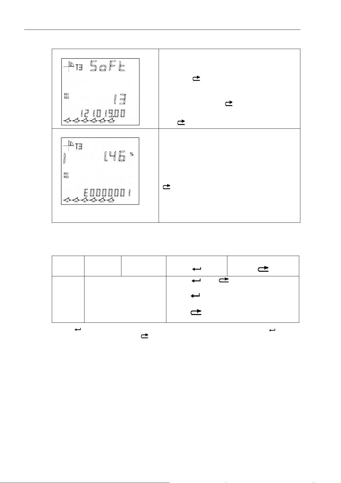
This screen shows B display area (software version).
At cyclic display mode, press "▲" or "▼" to enter key display
mode, press " " to switch to area B. Press "▲" or "▼" to
switch to software version number display. "Soft" means software version, "13" means product specification, "1210119"
means software version date and "00" means serial number of
software production. Press " " to enter second level display. You can press "▲" or "▼" to view active pulse constant,
reactive pulse constant, Modbus communication address.
Press " " to return to previous display.
Example 15:
This screen shows A display area (current unbalance rate)
and B display area (error code).
At cyclic display mode, press "▲" or "▼" to enter key display
mode. When A is selected, press "▲" or "▼" switch to current
unbalance rate option.
In the figure of A, current unbalance rate = 1.46%. Press
" " to switch to area B. Press "▲" or "▼" to switch to error
code display. "E" means error prompt, the 7 bits from right to
left mean respectively Phase A loss, Phase B loss, Phase C
loss, voltage phase reverse, Phase A current reverse, Phase
B current reverse, Phase C current reverse. For example,
"E0000001" means phase C current reverse fault occurs.
Key Setting Parameters
1. Key functions at parameter setting mode
Key symbol ▲▼
Function
1.Press " " once after adjusting parameters with "▲" and "▼" to display "Sure", and press " " once
again to alter parameters. Pressing " " immediately after "Sure" appears will cancel current alteration.
a) "▲" to switch digit or flip over;
b) "▼" to move cursor or flip over.
a) Press " " and " " at the same time to enter
setting screen.
b) Press " " to enter next menu or "confirm" parameter
setting.
c) Press " " to return to previous menu or "cancel" parameter setting
1
.
32
SICAM P38 P39, 3-phase Power Meter with Multi-Tariff function, User Manual
E50417-H8940-C564-4, Release Date 06.2018
Page 33
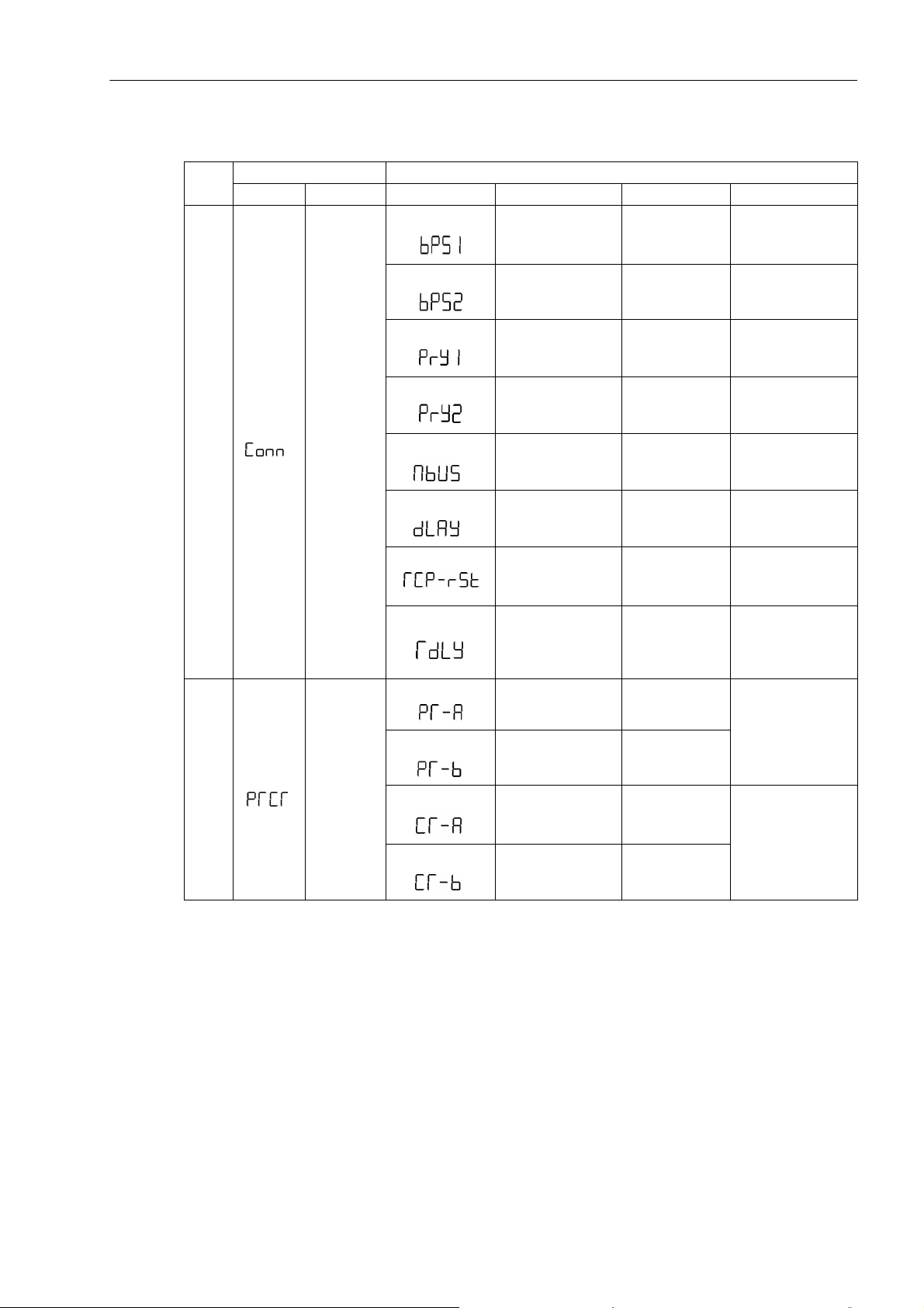
2. Data items configurable with key (Note 1)
st
level menu 2nd level menu
NO.
1
Symbol Definition Symbol Definition Range Remarks
Operation and Display
4.3 Key Definition
Baud rate 600 ... 38400
Baud rate 600 ... 38400
Parity
Parity
1
Communi-
cation
setting
Modbus address 0 ... 247 Default setting: 0
Modbus sending
delay
8E1/8o1/8n1/8n
2
8E1/8o1/8n1/8n
2
0 ... 2999
Default setting:
2400
Default setting:
2400
Default setting: 8E1
Default setting: 8E1
Unit: ms
Default setting: 10
Reset Ethernet port
Ethernet communication module
sending time inter-
2 ... 200 Unit: ms
val setting
Voltage ratio
integer part
0 ... 9999
Combination 0 ...
9999.9999
Voltage ratio
Ratio
2
setting
(Note 2)
decimal part
Current ratio
integer part
0 ... 9999
0 ... 9999
Default setting: 1
Combination 0 ...
9999.9999
Current ratio
decimal part
0 ... 9999
Default setting: 1
SICAM P38 P39, 3-phase Power Meter with Multi-Tariff function, User Manual
E50417-H8940-C564-4, Release Date 06.2018
33
Page 34
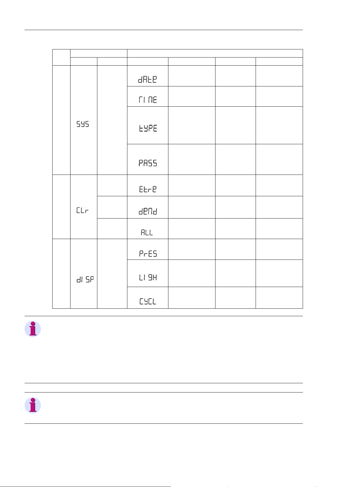
Operation and Display
4.3 Key Definition
NO.
st
level menu 2nd level menu
1
Symbol Definition Symbol Definition Range Remarks
Data
Time
3P4L
3
System
setting
Connection
3P3L_2CT
3P3L_3CT
AUto
3phase4wire
3phase3wire -2CT
3phase3wire -3CT
Automatic
6 bits in total, Set
L0 to L2 password
Password
Default setting:
000000
Clearing
extreme
value
4
Clearing
demand
Meter reset
Time of returning to
cyclic display state
1 ... 99
when no operation
Time of backlight
5
Display
setting
on when no operation (normally on
0 ... 99
Unit: min.
Default setting: 10
Unit: min.
Default setting: 10
when set to 0)
Interval of cyclic
display
Note
1 ... 99
Unit: sec
Default setting: 5
Password level (1 bit, 0 to 2) and password (6 bits) should be entered at first for key setting. Password level
and permission:
• L0 password-all parameters above are configurable;
• L1 password-all parameters above are configurable;
• L2 password-all parameters except for meter reset, clearing extreme value and PT/CT conversion ratio are
configurable.
Note
The meter should be reset after altering PT/CT ratio to ensure reasonable correspondence between
communication reading and displayed metering data.
34
SICAM P38 P39, 3-phase Power Meter with Multi-Tariff function, User Manual
E50417-H8940-C564-4, Release Date 06.2018
Page 35
Operation and Display
4.3 Key Definition
Note
For P39 device, the second communication port parameter setting can not be changed.
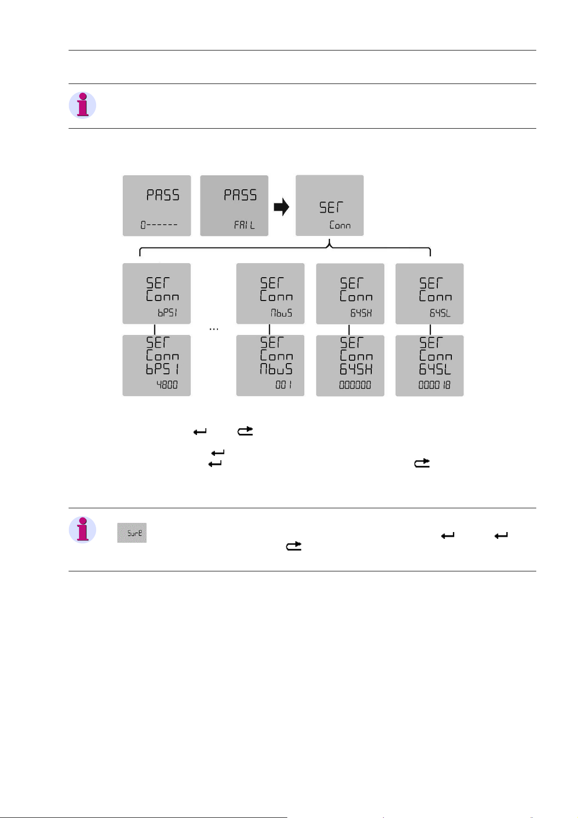
3. Parameter setting with keys (take "Conn communication setting" for example)
Figure 4-2 Parameter Setting with Keys
At any time, press " " and " " simultaneously to enter "PASS" screen. The first digit of displayed data
means password level and the remaining 6 data make up the password (press "▲" to change digits and "▼"
to move cursor). Press " " to confirm. "FAIL" will appear if password level and password are wrong. To reenter password, press " ". To quit and return to cyclic display state, enter " " (if specified error count is
reached, parameter setting function will be locked for certain period which is configurable in advance). If the
password is validated, you may enter the first-level menu. The figure shows the read-write items under "Conn"
menu: baud rate and communication address of RS485 port can be set.
Note
"SURE" screen appears after selecting or inputting parameter and pressing " ". Press " " once
again to activate new parameter. Pressing " " at any time during parameter setting will cancel setting or
return to previous menu.
■
SICAM P38 P39, 3-phase Power Meter with Multi-Tariff function, User Manual
E50417-H8940-C564-4, Release Date 06.2018
35
Page 36

Operation and Display
4.3 Key Definition
36
SICAM P38 P39, 3-phase Power Meter with Multi-Tariff function, User Manual
E50417-H8940-C564-4, Release Date 06.2018
Page 37

Installation and Wiring 5
5.1 Total Dimension 38
5.2 Precautions of Installation 38
5.3 Terminals and Wiring Diagram 39
SICAM P38 P39, 3-phase Power Meter with Multi-Tariff function, User Manual
E50417-H8940-C564-4, Release Date 06.2018
37
Page 38
Installation and Wiring
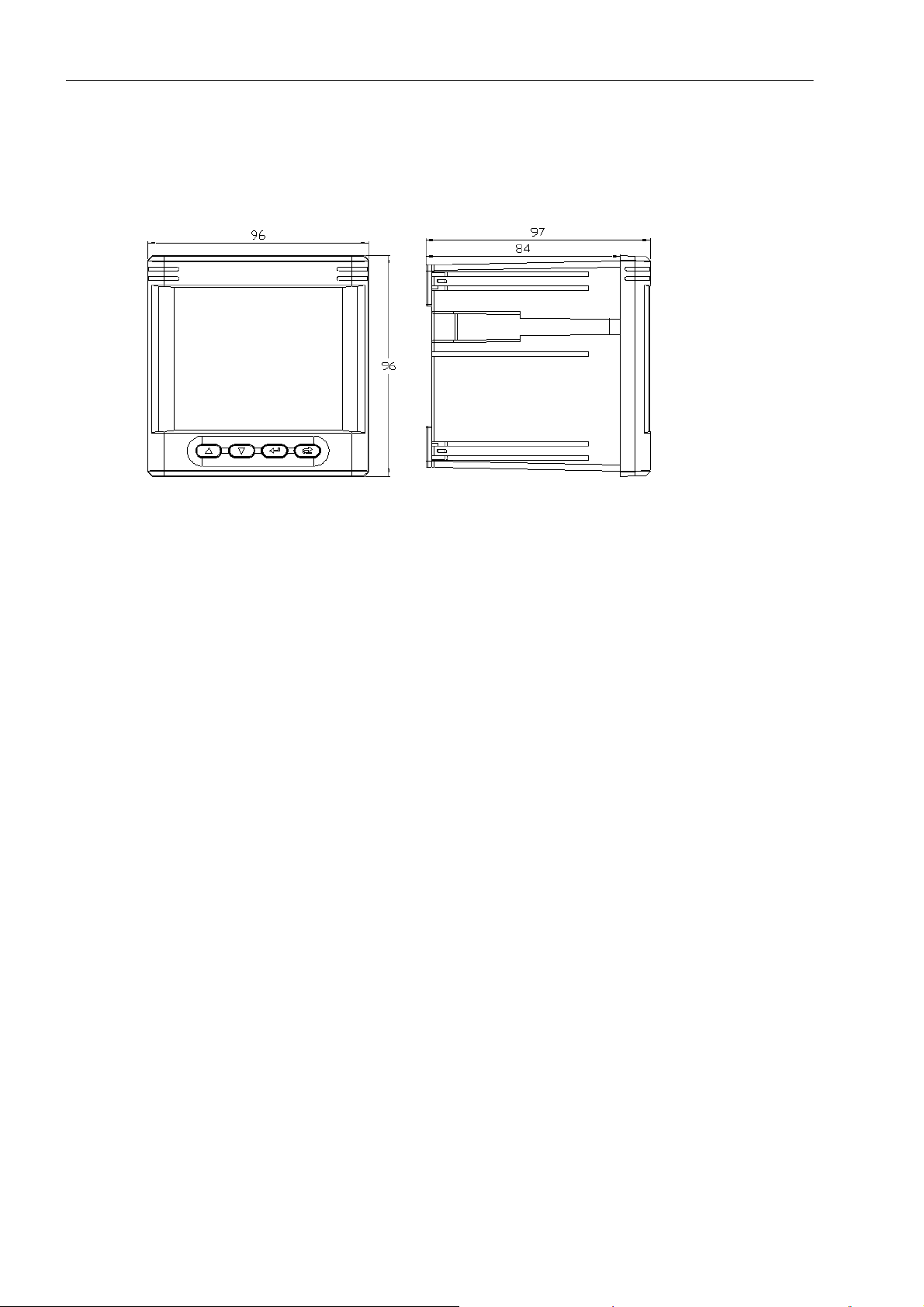
5.1 Total Dimension
5.1 Total Dimension
The figure below shows the total dimension of this product. Panel cut out size: 92 mm×92 mm
Figure 5-1 Total Dimension of Instrument
5.2 Precautions of Installation
1. Dry and well ventilated environment far away from thermal source and strong electric (magnetic) field is recommended for installation of this product.
2. Ambient temperature: -25 ℃ to +60 ℃ , humidity: ≤ 95% (no condensation)
3. This product should be firmly mounted to avoid accident arising from vibration.
4. For the reason of convenient installation, maintenance and operation and safety, enough space around this
product should be reserved during installation (especially when one panel for multiple meters).
5. Requirement for electric wiring: Stranded fire-retarded copper wire over 2.5 mm
circuit, 1.5 mm
and 1.0 mm
6. Requirement for electric connection: In voltage input circuit and operating power supply circuit, appropriate
fuses (such as 0.5 A fuse) should be connected and a CT short-circuit box should be provided to prevent
open circuit of CT wiring.
2
stranded fire-retarded copper wire should be used for voltage circuit and power supply circuit,
2
Shielded Twisted Pair should be used for RS485 communication.
2
should be used for current
38
SICAM P38 P39, 3-phase Power Meter with Multi-Tariff function, User Manual
E50417-H8940-C564-4, Release Date 06.2018
Page 39
5.3 Terminals and Wiring Diagram
Definition of Terminals (viewed from rear to front and from left to right)
1. Upper main terminals
Installation and Wiring
5.3 Terminals and Wiring Diagram
V+ V- NC NC R11 R12 R21 R22
Power supply
Note
Reserved
Reserved
Relay output 1
Relay output 2
NC means no connection, the same below.
2. Lower main terminals
V1 V2 V3 VN I11 I12 I21 I22 I31 I32
Phase A voltage
Phase B voltage
Phase C voltage
Phase A current input
Phase A current output
Phase B current input
Phase B current output
Phase C current input
Phase C current output
Neutral
Note
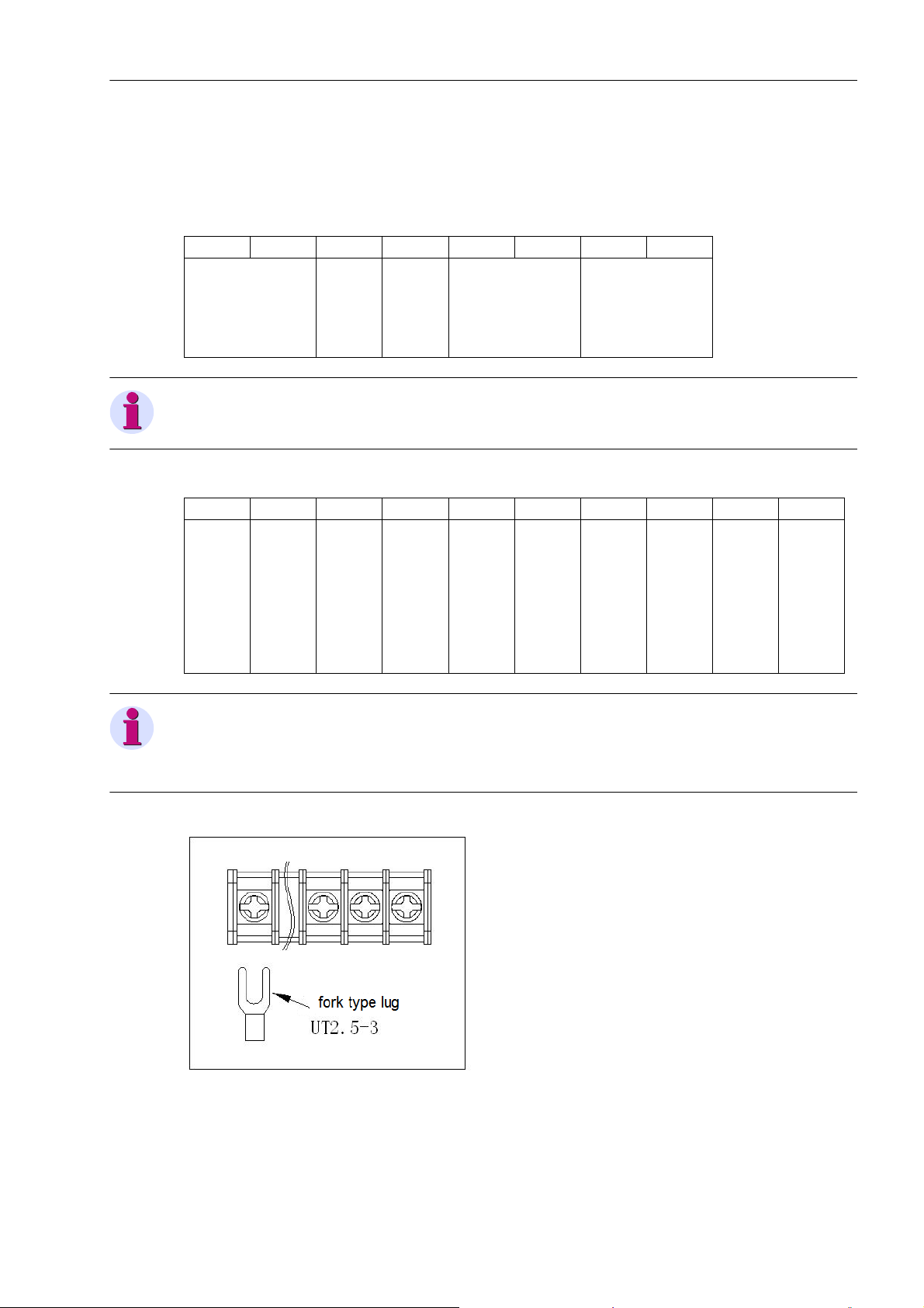
Main terminals are barrier terminals which can be connected using fork or ring-type lug (no more than 6.5 mm
wide). For cables to be connected to upper and lower main terminals, cold-pressed UT2.5-3 terminal is
recommended before connection. The diagram of connection is below.
Figure 5-2 Connection Diagram of Main Terminal
SICAM P38 P39, 3-phase Power Meter with Multi-Tariff function, User Manual
E50417-H8940-C564-4, Release Date 06.2018
39
Page 40
Installation and Wiring
5.3 Terminals and Wiring Diagram
3. Middle auxiliary terminal (For P38)
P+ Q+ COM1 DI1 DI2 DI3 DI4 COM2 A1 B1 A2 B2
Common pulse output terminal
Active pulse
Reactive pulse
Binary input 1
Binary input 2
Binary input 3
Binary input 4
Common binary input terminal
RS485 + 1
RS485 - 1
RS485 + 2
4. Middle auxiliary terminal (For P39)
RJ45 P+ Q+ COM1 DI1 DI2 DI3 DI4 COM2 A B
Common pulse output terminal
Active pulse output
Ethernet port
Reactive pulse output
Binary input 1
Binary input 2
Binary input 3
Binary input 4
Common binary input terminal
RS485 +
RS485 -
RS485 - 2
Note
Auxiliary terminal is pluggable.
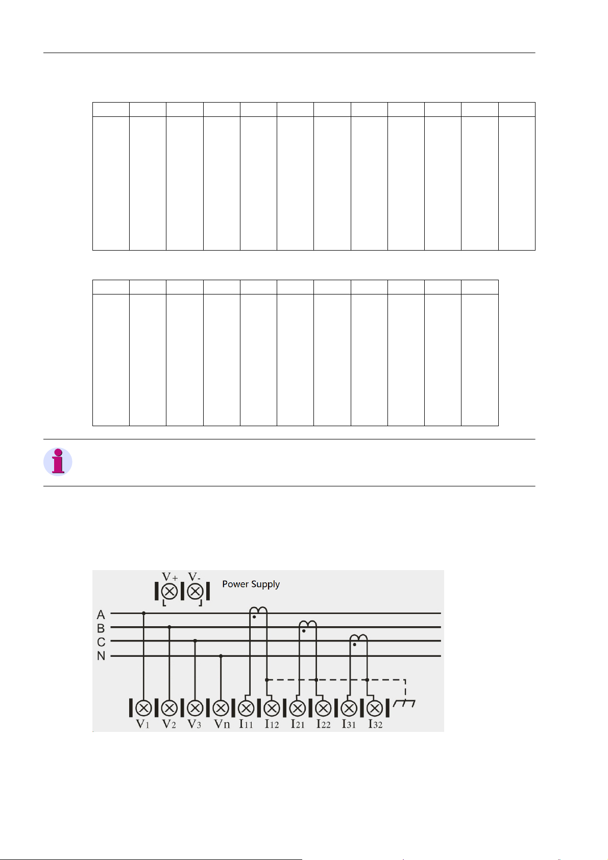
Wiring diagram
Wiring diagram of main terminal is showed below. "V+" and "V-" are power supply terminals. This product supports DC/AC input, with input voltage 40 V to 420 V. For 3-phase-3-wire connection, V
nected together, see Figure 5-5.
and V2 should be con-
n
40
Figure 5-3 Wiring Diagram of 3-phase-4-wire (W/O PT)
SICAM P38 P39, 3-phase Power Meter with Multi-Tariff function, User Manual
E50417-H8940-C564-4, Release Date 06.2018
Page 41
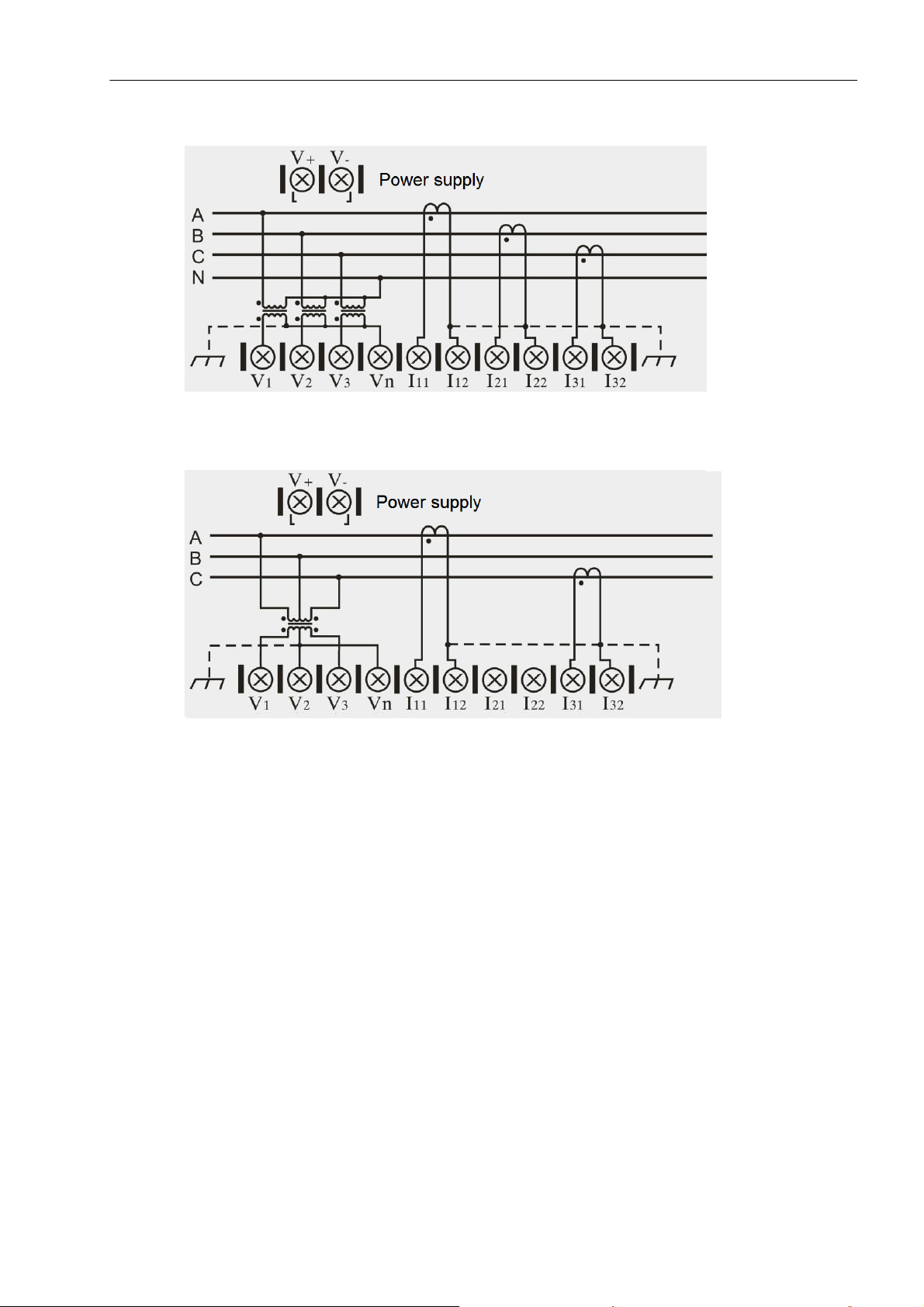
Figure 5-4 Wiring Diagram of 3-phase-4-wire (With PT)
Installation and Wiring
5.3 Terminals and Wiring Diagram
Figure 5-5 Wiring Diagram of 3-phase-3-wire
■
SICAM P38 P39, 3-phase Power Meter with Multi-Tariff function, User Manual
E50417-H8940-C564-4, Release Date 06.2018
41
Page 42

Installation and Wiring
5.3 Terminals and Wiring Diagram
42
SICAM P38 P39, 3-phase Power Meter with Multi-Tariff function, User Manual
E50417-H8940-C564-4, Release Date 06.2018
Page 43

Communication 6
6.1 Use of Communication 44
6.2 Introduction of MODBUS-RTU Communication Protocol 45
SICAM P38 P39, 3-phase Power Meter with Multi-Tariff function, User Manual
E50417-H8940-C564-4, Release Date 06.2018
43
Page 44
Communication
6.1 Use of Communication
6.1 Use of Communication
RS485 port of this meter supports MODBUS-RTU communication protocol. Even parity check is the default
setting for data byte check. MODBUS-RTU communication protocol can also be configured to odd parity check
or no verification (1 or 2 stop bits can be set without check). Baud rate of communication port could any of 600
bps, 1,200 bps, 2,400 bps, 4,800 bps, 9,600 bps, 19,200 bps and 38,400 bps.
RS485 port of this product should be connected using Shield Twisted Pair. When wiring, layout of the entire
network should be considered: length and orientation of communication cable, position of upper computer,
matched resistance at network end-point, communication converter, network scalability, network coverage,
EMI, etc.
Note
1. Wiring should be conducted strictly in accordance with requirement.
2. The power meter requiring no communication temporarily should be connected to RS485 network for easy
diagnosis and test.
3. The shielding layer side of cable connected with upper computer should be reliably earthed (PGND: ground,
cubicle, cabinet, etc.) to avoid two-point or multi-point earthing.
4. Shield Twisted Pair should be used for RS485 bus cable. For two twisted pairs, different colors are recom-
mended, one color for "A" side and another color for "B" side of 485 communication port.
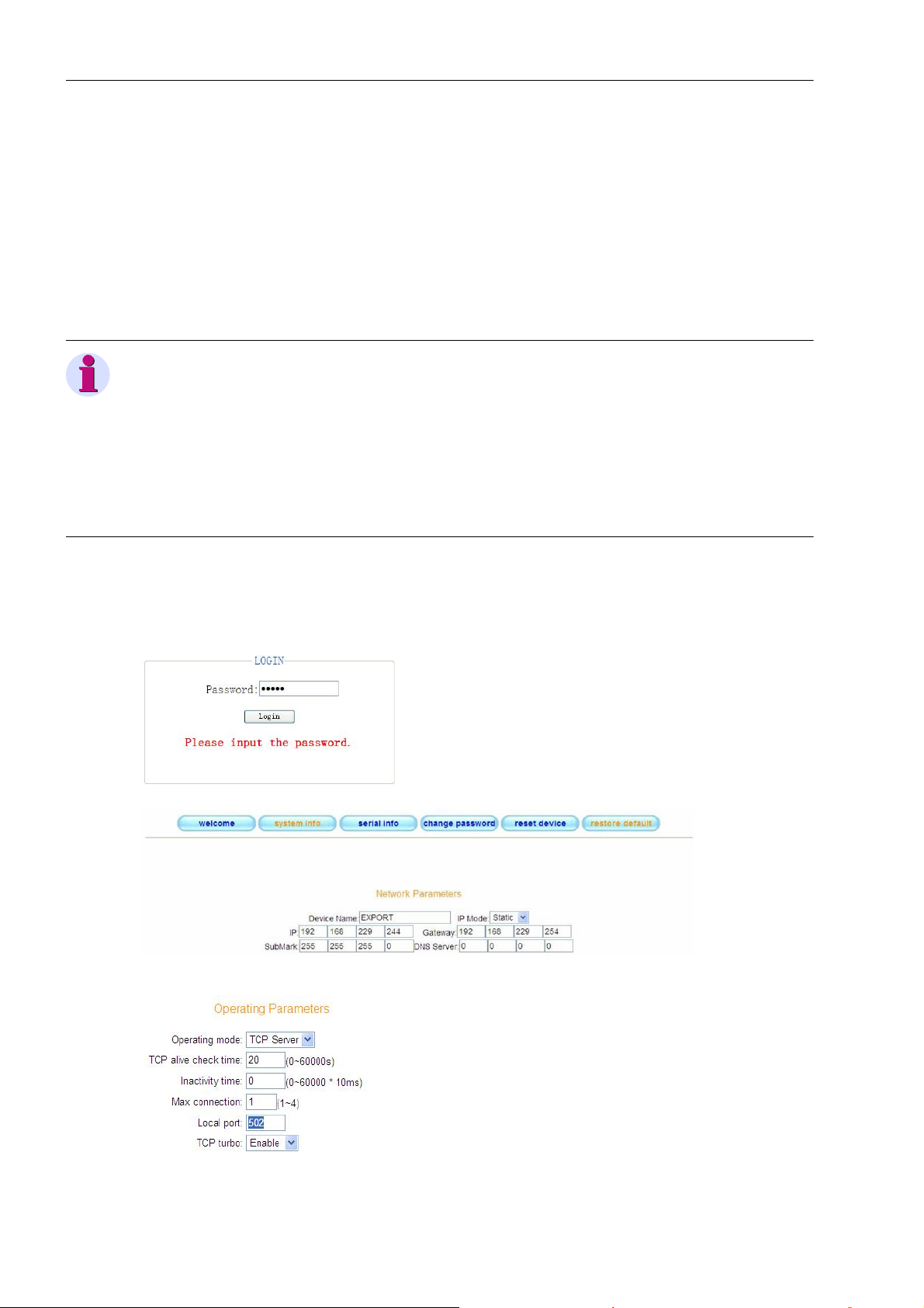
The RJ45 Ethernet port supports 10M/100 bits/s, device work on TCP Server mode, Modbus TCP connection
port fixed to 502.
Ethernet parameters are configured by WEB mode. Open the IE browser, enter device IP address in the
address bar (factory default 192.168.0.178), shown below login interface. Password is 88888.
44
SICAM P38 P39, 3-phase Power Meter with Multi-Tariff function, User Manual
E50417-H8940-C564-4, Release Date 06.2018
Page 45
6.2 Introduction of MODBUS-RTU Communication Protocol
6.2 Introduction of MODBUS-RTU Communication Protocol
6.2.1 Overview
Type of Protocol
This is MODBUS RTU protocol applicable to real-time communication of embedded electric energy meter. This
protocol defines the data exchange between terminal unit (slave) and Master, which is realized in the form of
RTU (remote terminal unit) of MODBUS. Asynchronous master-slave half-duplex communication is used.
Communication is initiated from master and slave responds after receiving request from master.
Communication response time < 0.2 sec.
Physical Layer
• Transmission interface: RS-485
• Communication address: 0 to 247
• Communication baud rate: 600 bps to 38,400 bps
• Communication media: Shield Twisted Pair
Data Link Layer (DLL)
• Transmission manner: asynchronous master-slave half-duplex
Communication
• Data frame format: 1 start bit, 8-digit data, even parity check bit, 1 stop bit (default)
• Data packet format:
Address Function Data CRC
8 bits 8 bits n*8 bits 16 bits
Data packet transmission sequence always uses identical address, function code, data and check code. Each
data packet should be transmitted as a continuous bit stream. When data packet from the master reaches
slave, slave matching the address field in data packet will receive and check the data. If no error, slave will
execute the request in data packet and send the responsive date packet to the master. The data packet sent
back by slave contains slave Address, Function executed, Data generated from function execution and CRC.
• Address
Address is at the beginning of data packet and consists of an 8-bit data which means slave address specified
by the master. Each slave address in the bus is unique. Valid address range is from 0 to 247. After the master
sends data packet, only slave matching the inquire address of the master will respond.
• Function
It describes which function is executed by slave. Meanings of all function codes are given below.
Code Definition Function
03 H Read data Read current binary value of one or more variables
10 H Preset multiple registers Overwrite values of several variables using specific binary value
• Data
It contains data required for executing specific function by slave or data acquired when slave responds inquiry
of master. Content of these data may be address code or data.
• CRC
Check code is 16-bit check data formed in data transmission for CRC of master and slave. Various
interferences exist in communication, so data transmitted during communication may change. CRC will avoid
data distortion during responsive transmission of master and slave and improves security and efficiency of
system. For formation rule of check code, see Annex 1.
SICAM P38 P39, 3-phase Power Meter with Multi-Tariff function, User Manual
E50417-H8940-C564-4, Release Date 06.2018
45
Page 46
Communication
6.2.2 Function of Application Layer
6.2.2 Function of Application Layer
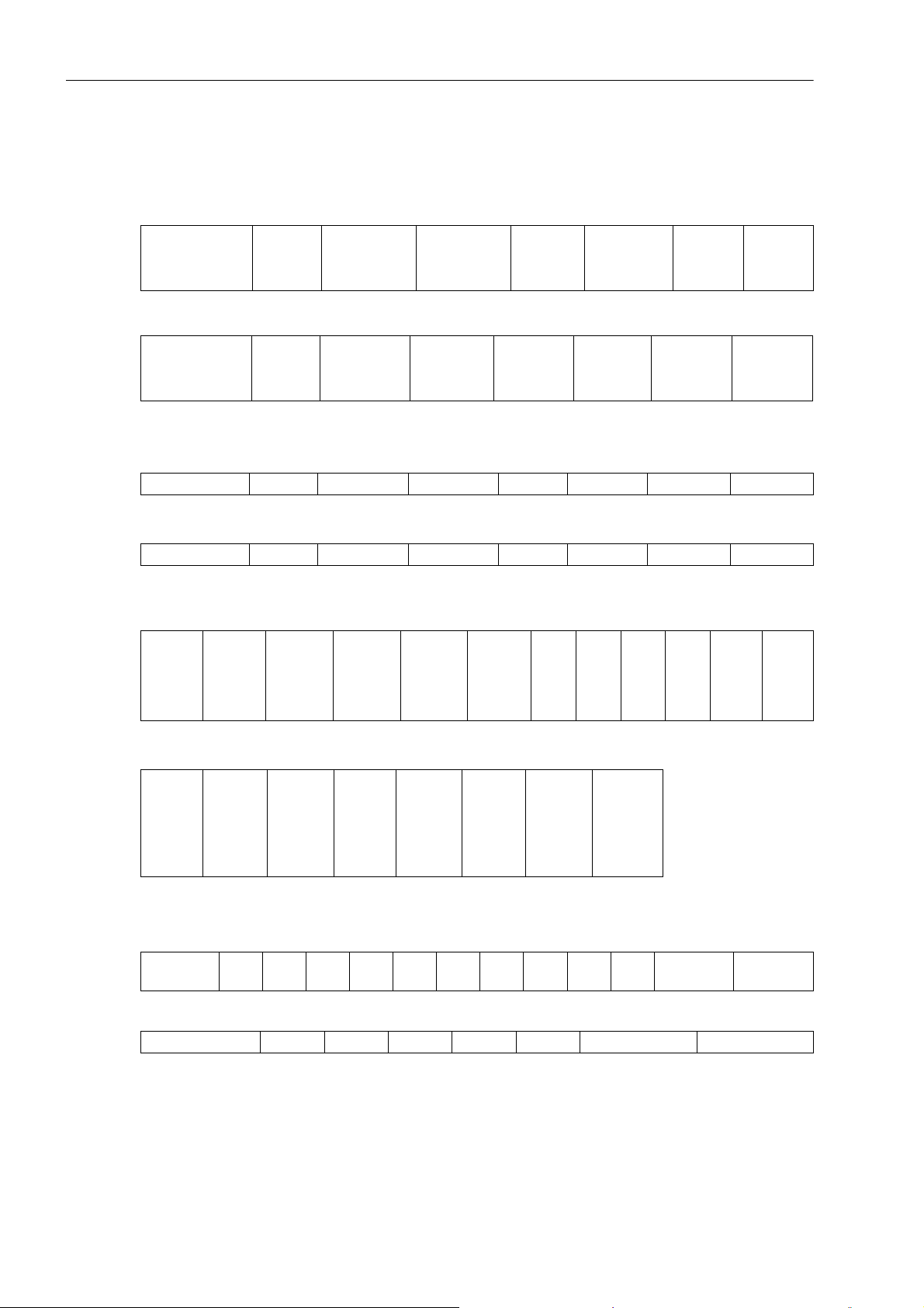
Read Data Command (function code 03 H)
• Down frame format
Communication
address (0-247)
Function
code
(03 H)
High byte of
start address
of data
• Response frame format
Communication
address (0-247)
Function
code
(03 H)
Number of
bytes of data
length
• Example
- Down frame of 3-phase voltage data read
Device address 03 H 10 H 00 H 00 H 03 H Low check High check
- Response frame
Device address 03 H 06 H Data 1 Data 2 ... Low check High check
Preset Multi-Register Command (function code 10 H)
• Down frame format
Device
address
0-247
Func-
tion
code
(10 H)
High byte
of start
address
of vari-
able
Low byte
of start
address
of vari-
able
Low byte of
start address
of data
Content of
data
High byte
of vari-
able
number
Content of
Low
byte of
variable
number
High byte
of length
of data
data
Byte
n of
data
Low byte of
length of
data
Content of
data
Byte
Byte
1 of
of
data
data
Low byte
of CRC
Low byte of
CRC
Byte
n of
data
High byte
Low
byte of
CRC
High byte
of CRC
of CRC
High
byte of
CRC
• Response frame format
Device
address
0-247
Func-
tion
code
(10 H)
High
byte of
start
address
of vari-
able
Low
byte of
start
address
of vari-
able
High
byte of
variable
number
Low
byte of
variable
number
Low byte
of CRC
High byte
of CRC
• Example
- Down frame when PT conversion ratio is 1234.5678 (hexadecimal notation of 12345678: 00BC 614EH)
Device
address
10 H 00 H 03 H 00 H 02 H 04 H 00 H BC H 61 H 4E H Low check High check
- Response frame
Device address 10 H 00 H 03 H 00 H 02 H Low check High check
46
SICAM P38 P39, 3-phase Power Meter with Multi-Tariff function, User Manual
E50417-H8940-C564-4, Release Date 06.2018
Page 47
Exception Response
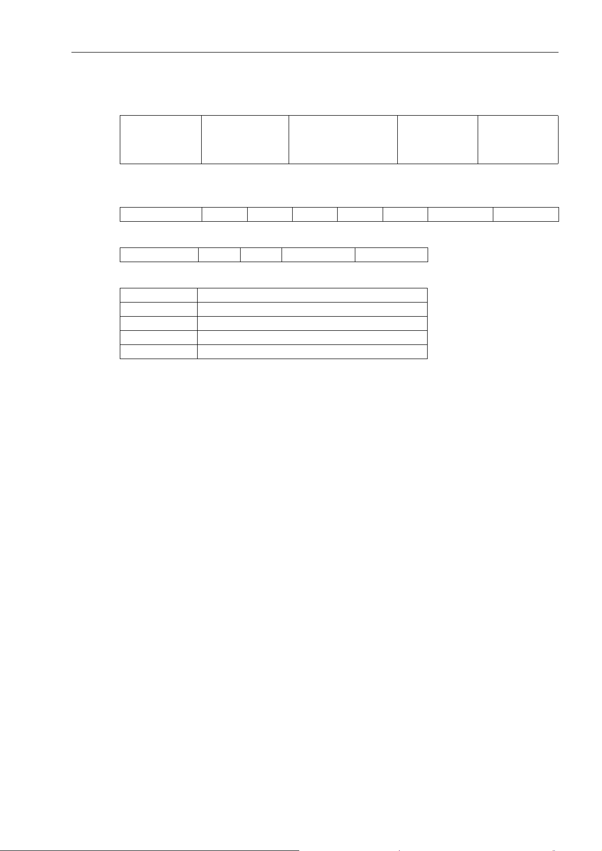
• Exception response frame format
Communication
address (0-247)
• Example
- Address data of illegal register read
Device address 03 H XX H XX H 00 H 01 H Low check High check
- Response frame
Device address 83 H 02 H Low check High check
• Exception code of MODBUS
Code Meaning
02 H Illegal data address
03 H Illegal data
10 H No permission
11 H Register length overflow
Function code
(80 H+03 H)
(80 H+10 H)
Communication
6.2.3 CRC Method
Exception code (XX H) Low byte of CRC High byte of CRC
6.2.3 CRC Method
CRC contains 2 bytes, namely 16-bit binary system. CRC is calculated with transmitting device and placed at
the tail of transmitted message. Receiving device recalculates CRC of message received and compares
whether CRC derived matches the received one. If not, error may occur.
To calculate CRC, preset all 16-bit registers to 1. Then, process each 8-bit data message one by one. Only 8bit data bit is used for CRC calculation and start bit and stop bit and parity check bit (if any) are not involved.
Steps of calculating CRC:
• Preset 16-bit register to hexadecimal FFFF (namely all to 1), and this register is called CRC register.
• Execute exclusive OR of low bytes of 1
• Shift the content of register rightwards by one bit (towards lower bit) and fill the highest bit with 0. Check the
lowest bit.
• If the lowest bit is 0, repeat step 3 (shift again); if it is 1, execute exclusive OR of CRC register and polynomial
A001 (1010 0000 0000 0001).
• Repeat step 3 and step 4 until shift rightwards 8 times. Now, all 8-bit data are processed.
• Repeat step 2 to step 5 to process next 8-bit data.
• The CRC register derived finally is CRC.
st
8-bit data and 16-bit CRC register and put the result in CRC register.
SICAM P38 P39, 3-phase Power Meter with Multi-Tariff function, User Manual
E50417-H8940-C564-4, Release Date 06.2018
47
Page 48
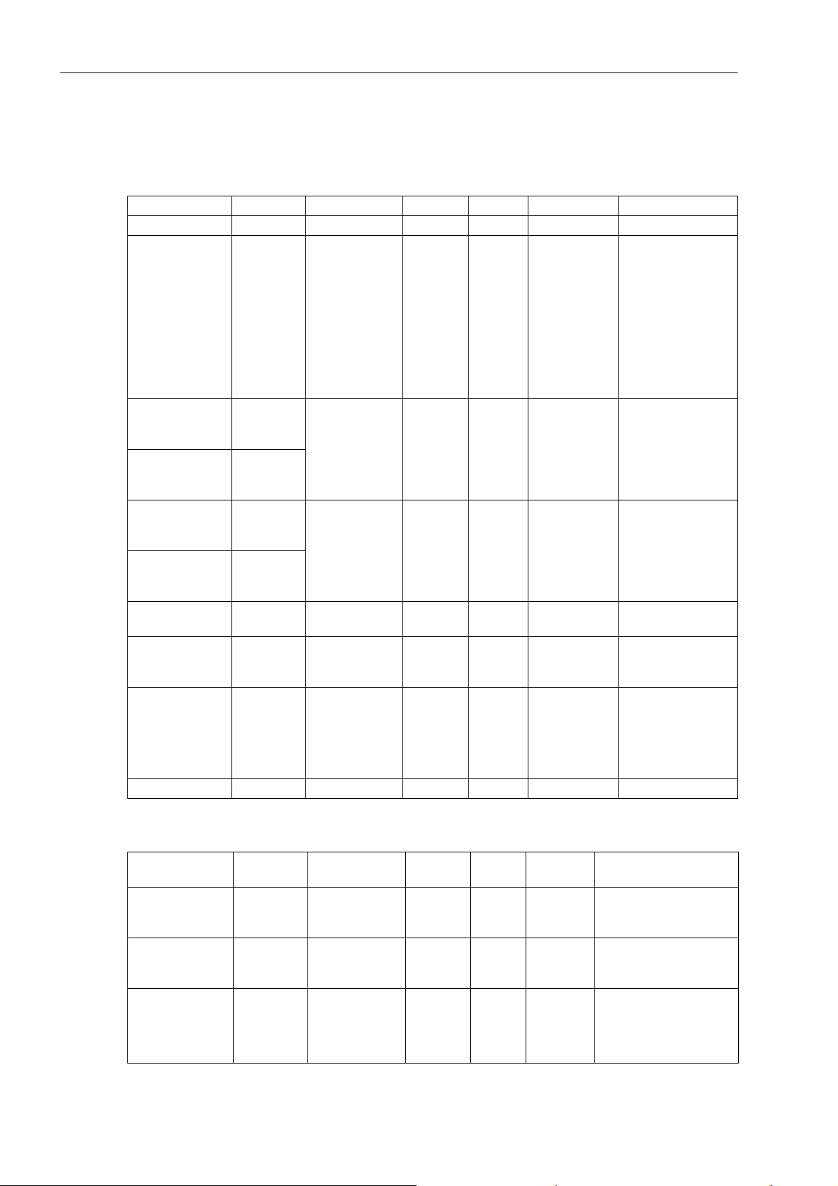
Communication
6.2.4 Information mapping table
6.2.4 Information mapping table
Common Parameters
Parameter Address Data Type Length R/W Data Range Remark
Modbus address 0000 H unsigned int 2 bytes R/W 0 ... 247
Baud rate of
communication
High 16 bits of
voltage conversion ratio
Low 16 bits of
voltage conversion ratio
High 16 bits of
current conversion ratio
Low 16 bits of
current conversion ratio
Clearing extreme
value
Control Ethernet
port
Parity 0020 H unsigned int 2 bytes R/W 0 ... 3
0001 H unsigned int 2 bytes R/W 0 ... 6
0002 H
unsigned long 4 bytes R/W 0 ... 99999999
0003 H
0004 H
unsigned long 4 bytes R/W 0 ... 99999999
0005 H
0006 H unsigned int 2 bytes W Arbitrary value
000D H unsigned int 2 bytes R/W 0 ... 2
0: 2400 bps
1: 4800 bps
2: 9600 bps
3: 19200 bps
4: 38400 bps
5: 600 bps
6: 1200 bps
PT ratio=set value/10,000, 10,000
as default when
PT=0
CT ratio=set value/10,000, 10,000
as default when
CT=0
0: power down
1: power up
2: restart
0: 8E1
1: 8o1
2: 8n1
Clearing demand 0021 H unsigned int 2 bytes W Arbitrary value
Relay Alarm Parameters
Parameter Address Data Type Length R/W
Relay output 1 0100 H unsigned int 2 bytes R/W 0 ... 1
Relay output 2 0101 H unsigned int 2 bytes R/W 0 ... 1
Binary inputs 0102 H unsigned int 2 bytes R
48
3: 8n2
Data
Range
Remark
Write operation is valid
when "alarm manner
control byte" is 0 or 2
Write operation is valid
when "alarm manner
control byte" is 0 or 1
High byte: binary input
status (note)
Low byte: binary output
status
SICAM P38 P39, 3-phase Power Meter with Multi-Tariff function, User Manual
E50417-H8940-C564-4, Release Date 06.2018
Page 49
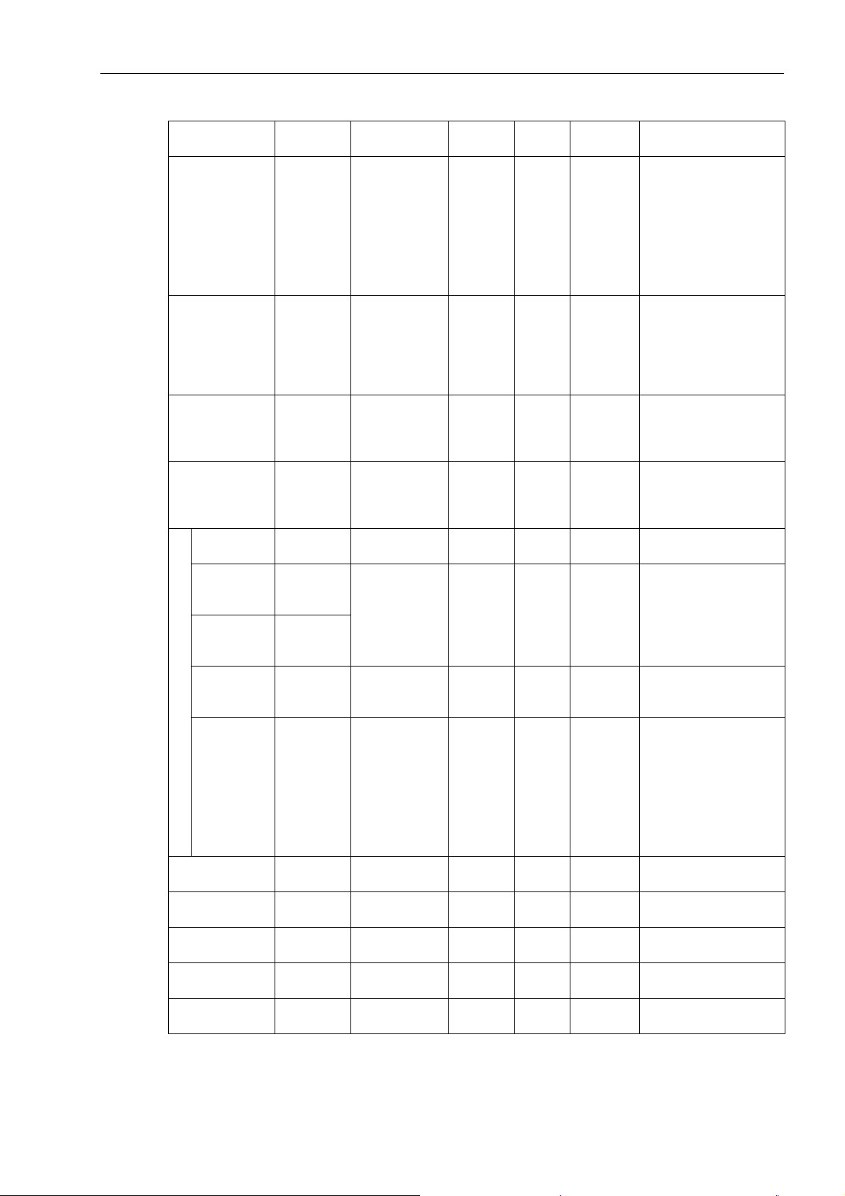
Communication
6.2.4 Information mapping table
Parameter Address Data Type Length R/W
Alarm manner
control byte
0103 H unsigned int 2 bytes R/W 0 ... 3
Data
Range
Alarm status byte 0106 H unsigned int 2 bytes R 0 ... 0x3F
BO1 Relay operation time
BO2 Relay operation time
Out-of-limit
data type
0107 H unsigned int 2 bytes R/W
0109 H unsigned int 2 bytes R/W
0110 H unsigned int 2 bytes R/W 0 ... 34 See alarm type table
0 or 100 ...
3000
0 or 100 ...
3000
High 16 bits
of out- of-limit
threshold
Low 16 bits
of out- of-limit
threshold
Alarm 1
Out-of-limit
detection
0111 H
unsigned long 4 bytes R/W
Arbitrary
value
0112 H
0113 H unsigned int 2 bytes R/W 0 ... 1 0: over, 1: below
type
Alarm port 0114 H unsigned int 2 bytes R/W 0 ... 3
Alarm 2
Alarm 3
Alarm 4
Alarm 5
Alarm 6
0115 H ...
0119 H
011A H ...
011E H
011F H ...
0123 H
0124 H ...
0128 H
0129 H ...
012D H
10 bytes R/W See Alarm 1
10 bytes R/W See Alarm 1
10 bytes R/W See Alarm 1
10 bytes R/W See Alarm 1
10 bytes R/W See Alarm 1
Remark
0: turn off alarm function
1: relay output 1 is used
for alarm
2: relay output 2 is used
for alarm
3: output ports 1 and 2
are all used for alarm
From low to high, each
bit means status of an
alarm group:
0: no alarm activated
1: in alarm status
Unit: ms. Value 0 is for
latched output; value
100~3000 for pulse
output
Unit: ms. Value 0 is for
latched output; value
100~3000 for pulse
output
Threshold=set value/100
0: off
1: alarm output to relay
output 1
2: alarm output to relay
output 2
3: alarm output to output
ports 1 and 2
SICAM P38 P39, 3-phase Power Meter with Multi-Tariff function, User Manual
E50417-H8940-C564-4, Release Date 06.2018
49
Page 50
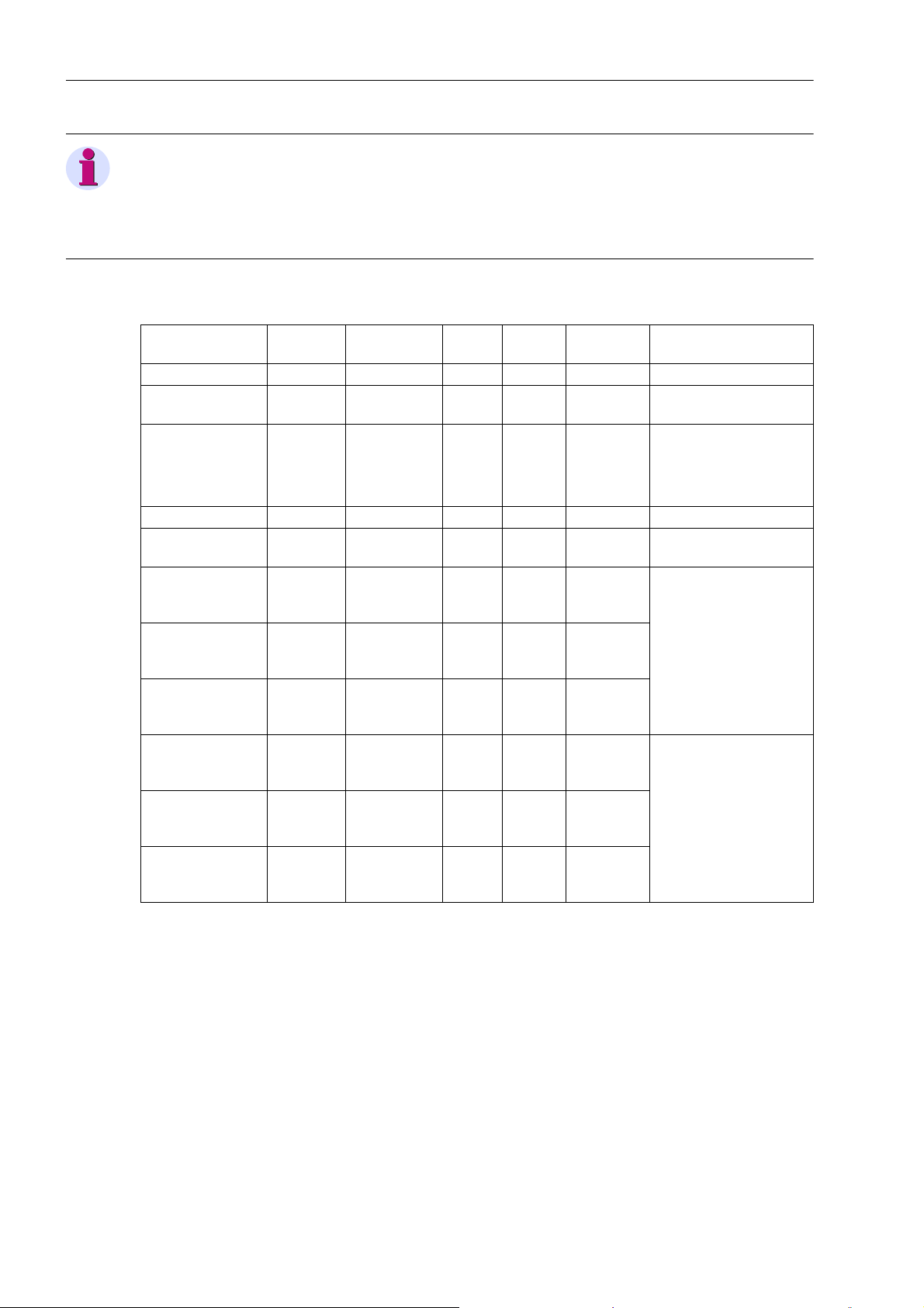
Communication
6.2.4 Information mapping table
Note
High bytes BIT0 to BIT3 respectively mean status of binary input 1 to 4. Bit value 0 means input is open while
1 means input is closed.
Low bytes BIT0 and BIT1 respectively mean status of relay output 1 and 2. Bit value 0 means contact is open
(relay no operation) while 1 means contact is closed (relay closed).
Other Parameters
Parameter Address Data Type Length R/W
Data
Range
Demand interval 0130 H unsigned int 2 bytes R/W 1 ... 60 Unit: min.
Sliding window
time
0131 H unsigned int 2 bytes R/W
1 ... 60 Unit: min.
3-phase-3-wire 0: 100 V;
Voltage specification
0134 H unsigned int 2 bytes R/W 0 ... 3
3: 380 V;
3-phase-4-wire 1: 220 V;
2: 57.7 V;
Cyclic display time 0132 H unsigned int 2 bytes R/W 1 ... 99 Unit: sec
Number of cyclic
display items
st
1
screen of cyclic
display item of
0133 H unsigned int 2 bytes R/W 00 ... FF
0140 H unsigned int 2 bytes R/W 0 ... 999
screen A
Number n screen
of cyclic display
item of screen A
... unsigned int 2 bytes R/W 0 ... 999
See cyclic display code
table of area A
16th screen of
cyclic display item
014F H unsigned int 2 bytes R/W 0 ... 999
of screen A
st
1
screen of cyclic
display item of
0150 H unsigned int 2 bytes R/W 0 ... 999
screen B
Number n screen
of cyclic display
item of screen B
th
screen of
16
cyclic display item
... unsigned int 2 bytes R/W 0 ... 999
015F H unsigned int 2 bytes R/W 0 ... 999
See cyclic display code
table of area B
of screen B
Remark
50
SICAM P38 P39, 3-phase Power Meter with Multi-Tariff function, User Manual
E50417-H8940-C564-4, Release Date 06.2018
Page 51
Communication
6.2.4 Information mapping table
Instantaneous Such as Voltage, Current, Active/Reactive and Apparent Power, Power Factor, Frequency, Unbalance and Current Demand
Parameter Address Data Type Length R/W Data Range Unit
Phase A voltage 1000 H unsigned int 2 bytes R 0 ... 65535 0.01 V
Phase B voltage 1001 H unsigned int 2 bytes R 0 ... 65535 0.01 V
Phase C voltage 1002 H unsigned int 2 bytes R 0 ... 65535 0.01 V
Average phase voltage 1003 H unsigned int 2 bytes R 0 ... 65535 0.01 V
Uab line voltage 1004 H unsigned int 2 bytes R 0 ... 65535 0.01 V
Ubc line voltage 1005 H unsigned int 2 bytes R 0 ... 65535 0.01 V
Uca line voltage 1006 H unsigned int 2 bytes R 0 ... 65535 0.01 V
Average line voltage 1007 H unsigned int 2 bytes R 0 ... 65535 0.01 V
Phase A current 1008 H unsigned int 2 bytes R 0 ... 65535 0.001 A
Phase B current 1009 H unsigned int 2 bytes R 0 ... 65535 0.001 A
Phase C current 100A H unsigned int 2 bytes R 0 ... 65535 0.001 A
Average current 100B H unsigned int 2 bytes R 0 ... 65535 0.001 A
Neutral current 100C H unsigned int 2 bytes R 0 ... 65535 0.001 A
Phase A active power 100D H signed int 2 bytes R -32767 ... 32767 1 W
Phase B active power 100E H signed int 2 bytes R -32767 ... 32767 1 W
Phase C active power 100F H signed int 2 bytes R -32767 ... 32767 1 W
Total active power 1010 H signed int 2 bytes R -32767 ... 32767 1 W
Phase A reactive power 1011 H signed int 2 bytes R -32767 ... 32767 1 var
Phase B reactive power 1012 H signed int 2 bytes R -32767 ... 32767 1 var
Phase C reactive power 1013 H signed int 2 bytes R -32767 ... 32767 1 var
Total reactive power 1014 H signed int 2 bytes R -32767 ... 32767 1 var
Phase A apparent
power
Phase B apparent
power
Phase C apparent
power
1015 H signed int 2 bytes R -32767 ... 32767 1 VA
1016 H signed int 2 bytes R -32767 ... 32767 1 VA
1017 H signed int 2 bytes R -32767 ... 32767 1 VA
Total apparent power 1018 H signed int 2 bytes R -32767 ... 32767 1 VA
Phase A power factor 1019 H signed int 2 bytes R -1000 ... 1000 0.001
Phase B power factor 101A H signed int 2 bytes R -1000 ... 1000 0.001
Phase C power factor 101B H signed int 2 bytes R -1000 ... 1000 0.001
Total power factor 101C H signed int 2 bytes R -1000 ... 1000 0.001
Frequency 101D H unsigned int 2 bytes R 0 ... 65535 0.01 Hz
Voltage unbalance rate 101E H unsigned int 2 bytes R 0 ... 65535 0.01%
Current unbalance rate 101F H unsigned int 2 bytes R 0 ... 65535 0.01%
Current active demand 1020 H signed int 2 bytes R -32767 ... 32767 1 W
Current reactive
demand
Current apparent
demand
1021 H signed int 2 bytes R -32767 ... 32767 1 var
1022 H signed int 2 bytes R -32767 ... 32767 1 VA
Phase A angle 1023 H unsigned int 2 bytes R 0 ... 3600 0.1
Phase B angle 1024 H unsigned int 2 bytes R 0 ... 3600 0.1
Phase C angle 1025 H unsigned int 2 bytes R 0 ... 3600 0.1
Current Phase A current
demand
1026 H unsigned int 2 bytes R 0 ... 65535 0.001 A
SICAM P38 P39, 3-phase Power Meter with Multi-Tariff function, User Manual
E50417-H8940-C564-4, Release Date 06.2018
51
Page 52
Communication
6.2.4 Information mapping table
Parameter Address Data Type Length R/W Data Range Unit
Current Phase B current
demand
Current Phase C current
demand
Phase A fundamental
voltage
Phase B fundamental
harmonic voltage
Phase C fundamental
harmonic voltage
nd
Phase A 2
harmonic
voltage
nd
Phase B 2
harmonic
voltage
nd
Phase C 2
harmonic
voltage
Phase A No. n harmonic
voltage
Phase B No. n harmonic
voltage
Phase C No. n harmonic
voltage
th
Phase A 50
harmonic
voltage
th
Phase B 50
harmonic
voltage
th
Phase C 50
harmonic
voltage
Phase A fundamental
current
Phase B fundamental
current
Phase C fundamental
current
nd
Phase A 2
harmonic
current
Phase B 2nd harmonic
current
nd
Phase C 2
harmonic
current
Phase A No. n harmonic
current
Phase B No. n harmonic
current
Phase C No. n harmonic
current
th
Phase A 50
harmonic
current
Phase B 50
th
current
Phase C 50
th
current
harmonic
harmonic
1027 H unsigned int 2 bytes R 0 ... 65535 0.001 A
1028 H unsigned int 2 bytes R 0 ... 65535 0.001 A
1100 H unsigned int 2 bytes R 0 ... 65535 0.01 V
1101 H unsigned int 2 bytes R 0 ... 65535 0.01 V
1102 H unsigned int 2 bytes R 0 ... 65535 0.01 V
1103 H unsigned int 2 bytes R 0 ... 65535 0.01 V
1104 H unsigned int 2 bytes R 0 ... 65535 0.01 V
1105 H unsigned int 2 bytes R 0 ... 65535 0.01 V
... unsigned int 2 bytes R 0 ... 65535 0.01 V
... unsigned int 2 bytes R 0 ... 65535 0.01 V
... unsigned int 2 bytes R 0 ... 65535 0.01 V
1193 H unsigned int 2 bytes R 0 ... 65535 0.01 V
1194 H unsigned int 2 bytes R 0 ... 65535 0.01 V
1195 H unsigned int 2 bytes R 0 ... 65535 0.01 V
1200 H unsigned int 2 bytes R 0 ... 65535 0.001 A
1201 H unsigned int 2 bytes R 0 ... 65535 0.001 A
1202 H unsigned int 2 bytes R 0 ... 65535 0.001 A
1203 H unsigned int 2 bytes R 0 ... 65535 0.001 A
1204 H unsigned int 2 bytes R 0 ... 65535 0.001 A
1205 H unsigned int 2 bytes R 0 ... 65535 0.001 A
... unsigned int 2 bytes R 0 ... 65535 0.001 A
... unsigned int 2 bytes R 0 ... 65535 0.001 A
... unsigned int 2 bytes R 0 ... 65535 0.001 A
1293 H unsigned int 2 bytes R 0 ... 65535 0.001 A
1294 H unsigned int 2 bytes R 0 ... 65535 0.001 A
1295 H unsigned int 2 bytes R 0 ... 65535 0.001 A
52
SICAM P38 P39, 3-phase Power Meter with Multi-Tariff function, User Manual
E50417-H8940-C564-4, Release Date 06.2018
Page 53
Communication
6.2.4 Information mapping table
Parameter Address Data Type Length R/W Data Range Unit
Phase A voltage 2nd harmonic ratio
nd
Phase B voltage 2
har-
monic ratio
Phase C voltage 2nd
harmonic ratio
Phase A voltage No. n
harmonic ratio
Phase B voltage No. n
harmonic ratio
Phase C voltage No. n
harmonic ratio
th
Phase A voltage 50
harmonic ratio
th
Phase B voltage 50
harmonic ratio
Phase C voltage 50th
harmonic ratio
nd
Phase A current 2
har-
monic ratio
nd
Phase B current 2
har-
monic ratio
Phase C current 2nd harmonic ratio
Phase A current No. n
harmonic ratio
Phase B current No. n
harmonic ratio
Phase C current No. n
harmonic ratio
th
Phase A current 50
harmonic ratio
th
Phase B current 50
harmonic ratio
Phase C current 50th
harmonic ratio
Phase A voltage waveform distortion
Phase B voltage waveform distortion
Phase C voltage waveform distortion
Phase A current waveform distortion
Phase B current waveform distortion
Phase C current waveform distortion
1303 H unsigned int 2 bytes R 0 ... 10000 0.01%
1304 H unsigned int 2 bytes R 0 ... 10000 0.01%
1305 H unsigned int 2 bytes R 0 ... 10000 0.01%
... unsigned int 2 bytes R 0 ... 10000 0.01%
... unsigned int 2 bytes R 0 ... 10000 0.01%
... unsigned int 2 bytes R 0 ... 10000 0.01%
1393 H unsigned int 2 bytes R 0 ... 10000 0.01%
1394 H unsigned int 2 bytes R 0 ... 10000 0.01%
1395 H unsigned int 2 bytes R 0 ... 10000 0.01%
1403 H unsigned int 2 bytes R 0 ... 10000 0.01%
1404 H unsigned int 2 bytes R 0 ... 10000 0.01%
1405 H unsigned int 2 bytes R 0 ... 10000 0.01%
... unsigned int 2 bytes R 0 ... 10000 0.01%
... unsigned int 2 bytes R 0 ... 10000 0.01%
... unsigned int 2 bytes R 0 ... 10000 0.01%
1493 H unsigned int 2 bytes R 0 ... 10000 0.01%
1494 H unsigned int 2 bytes R 0 ... 10000 0.01%
1495 H unsigned int 2 bytes R 0 ... 10000 0.01%
1500 H unsigned int 2 bytes R 0 ... 10000 0.01%
1501 H unsigned int 2 bytes R 0 ... 10000 0.01%
1502 H unsigned int 2 bytes R 0 ... 10000 0.01%
1503 H unsigned int 2 bytes R 0 ... 10000 0.01%
1504 H unsigned int 2 bytes R 0 ... 10000 0.01%
1505 H unsigned int 2 bytes R 0 ... 10000 0.01%
SICAM P38 P39, 3-phase Power Meter with Multi-Tariff function, User Manual
E50417-H8940-C564-4, Release Date 06.2018
53
Page 54
Communication
6.2.4 Information mapping table
Instantaneous such as voltage, current, active/reactive and apparent power (4 Bytes formate)
Parameter Address Data Type Length R/W Data Range Unit
Phase A voltage higher
16 bits
Phase A voltage lower
16 bits
Phase B voltage higher
16 bits
Phase B voltage lower
16 bits
Phase C voltage higher
16 bits
Phase C voltage lower
16 bits
Average phase voltage
higher 16 bits
Average phase voltage
lower 16 bits
Uab line voltage higher
16 bits
Uab line voltage lower
16 bits
Ubc line voltage higher
16 bits
Ubc line voltage lower
16 bits
Uca line voltage higher
16 bits
Uca line voltage lower
16 bits
Average line voltage
higher 16 bits
Average line voltage
lower 16 bits
Phase A current higher
16 bits
Phase A current lower
16 bits
Phase B current higher
16 bits
Phase B current lower
16 bits
Phase C current higher
16 bits
Phase C current lower
s
16 bit
A
verage current higher
16 bits
Average current lower
16 bits
1800 H
1801 H
1802 H
1803 H
1804 H
1805 H
1806 H
1807 H
1808 H
1809 H
180A H
180B H
180C H
180D H
180E H
180F H
1810 H
1811 H
1812 H
1813 H
1814 H
1815 H
1816 H
1817 H
unsigned
long
unsigned
long
unsigned
long
unsigned
long
unsigned
long
unsigned
long
unsigned
long
unsigned
long
unsigned
long
unsigned
long
unsigned
long
unsigned
long
4 bytes R 0 ... 9999999 0.001 V
4 bytes R 0 ... 9999999 0.001 V
4 bytes R 0 ... 9999999 0.001 V
4 bytes R 0 ... 9999999 0.001 V
4 bytes R 0 ... 9999999 0.001 V
4 bytes R 0 ... 9999999 0.001 V
4 bytes R 0 ... 9999999 0.001 V
4 bytes R 0 ... 9999999 0.001 V
4 bytes R 0 ... 99999999 0.0001 A
4 bytes R 0 ... 99999999 0.0001 A
4 bytes R 0 ... 99999999 0.0001 A
4 bytes R 0 ... 99999999 0.0001 A
54
SICAM P38 P39, 3-phase Power Meter with Multi-Tariff function, User Manual
E50417-H8940-C564-4, Release Date 06.2018
Page 55
Communication
6.2.4 Information mapping table
Parameter Address Data Type Length R/W Data Range Unit
Neutral current higher
16 bits
Neutral current lower
16 bits
Phase A active power
higher 16 bits
Phase A active power
lower 16 bits
Phase B active power
higher 16 bits
Phase B active power
lower 16 bits
Phase C active power
higher 16 bits
Phase C active power
lower 16 bits
Total active power
higher 16 bits
Total active power
lower 16 bits
Phase A reactive power
higher 16 bits
Phase A reactive power
lower 16 bits
Phase B reactive power
higher 16 bits
Phase B reactive power
lower 16 bits
Phase C reactive power
higher 16 bits
Phase C reactive power
lower 16 bits
Total reactive power
higher 16 bits
Total reactive power
lower 16 bits
Phase A apparent
power higher 16 bits
Phase A apparent
power lower 16 bits
Phase B apparent
power higher 16 bits
Phase B apparent
power lower 16 bits
Phase C apparent
power higher 16 bits
Phase C apparent
power lower 16 bits
Total apparent power
higher 16 bits
Total apparent power
lower 16 bits
1818 H
1819 H
181A H
181B H
181C H
181D H
181E H
181F H
1820 H
1821 H
1822 H
1823 H
1824 H
1825 H
1826 H
1827 H
1828 H
1829 H
182A H
182B H
H
182C
182D H
182E H
182F H
1830 H
1831 H
unsigned
long
4 bytes R 0 ... 99999999 0.0001 A
signed long 4 bytes R
signed long 4 bytes R
signed long 4 bytes R
signed long 4 bytes R
signed long 4 bytes R
signed long 4 bytes R
signed long 4 bytes R
signed long 4 bytes R
signed long 4 bytes R
signed long 4 bytes R
signed long 4 bytes R
signed long 4 bytes R
-99999999 ...
99999999
-99999999 ...
99999999
-99999999 ...
99999999
-99999999 ...
99999999
-99999999 ...
99999999
-99999999 ...
99999999
-99999999 ...
99999999
-99999999 ...
99999999
-99999999 ...
99999999
-99999999 ...
99999999
-99999999 ...
99999999
-99999999 ...
99999999
0.1 W
0.1 W
0.1 W
0.1 W
0.1 var
0.1 var
0.1 var
0.1 var
0.1 VA
0.1 VA
0.1 VA
0.1 VA
SICAM P38 P39, 3-phase Power Meter with Multi-Tariff function, User Manual
E50417-H8940-C564-4, Release Date 06.2018
55
Page 56
Communication
6.2.4 Information mapping table
Power Parameters
Parameter Address Data Type Length R/W Data Range Unit
Phase A active power
high 16 bits
Phase A active power
low 16 bits
Phase B active power
high 16 bits
Phase B active power
low 16 bits
Phase C active power
high 16 bits
Phase C active power
low 16 bits
Total active power high
16 bits
Total active power low
16 bits
Phase A reactive
power high 16 bits
Phase A reactive
power low 16 bits
Phase B reactive
power high 16 bits
Import Phase B reactive
power low 16 bits
Phase C reactive
power high 16 bits
Phase C reactive
power low 16 bits
Total reactive power
high 16 bits
Total reactive power
low 16 bits
T1 active power high16
bits
T1 active power low16
bits
T2 active power high16
bits
T2 active power low16
bits
T3 active power high16
bits
T3 active power low16
bits
active power high16
T4
bits
T4 active power low16
bits
2000 H
2001 H
2002 H
2003 H
2004 H
2005 H
2006 H
2007 H
2008 H
2009 H
200A H
200B H
200C H
200D H
200E H
200F H
2010 H
2011 H
2012 H
2013 H
2014 H
2015 H
2016 H
2017 H
unsigned
long
unsigned
long
unsigned
long
unsigned
long
unsigned
long
unsigned
long
unsigned
long
unsigned
long
unsigned
long
unsigned
long
unsigned
long
unsigned
long
4 bytes R 0 ... 4294967295 0.1 Wh
4 bytes R 0 ... 4294967295 0.1 Wh
4 bytes R 0 ... 4294967295 0.1 Wh
4 bytes R 0 ... 4294967295 0.1 Wh
4 bytes R 0 ... 4294967295 0.1 varh
4 bytes R 0 ... 4294967295 0.1 varh
4 bytes R 0 ... 4294967295 0.1 varh
4 bytes R 0 ... 4294967295 0.1 varh
4 bytes R 0 ... 4294967295 0.1 Wh
4 bytes R 0 ... 4294967295 0.1 Wh
4 bytes R 0 ... 4294967295 0.1 Wh
4 bytes R 0 ... 4294967295 0.1 Wh
56
SICAM P38 P39, 3-phase Power Meter with Multi-Tariff function, User Manual
E50417-H8940-C564-4, Release Date 06.2018
Page 57
Communication
6.2.4 Information mapping table
Parameter Address Data Type L ength R/W Data Range Unit
T5 active power high16
bits
T5 active power low16
bits
T6 active power high16
bits
T6 active power low16
bits
T1 reactive power
high16 bits
T1 reactive power
low16 bits
T2 reactive power
high16 bits
T2 reactive power
low16 bits
T3 reactive power
high16 bits
T3 reactive power
low16 bits
T4 reactive power
high16 bits
T4 reactive power
low16 bits
T5 reactive power
high16 bits
T5 reactive power
low16 bits
T6 reactive power
high16 bits
T6 reactive power
low16 bits
Phase A active power
high 16 bits
Phase A active power
low 16 bits
Phase B active power
high 16 bits
Phase B active power
low 16 bits
Phase C active power
high 16 bits
Phase C active power
low 16 bits
Total active power high
16 bits
Total active power low
16 bits
Export Phase A reactive
power high 16 bits
Phase A reactive
power low 16 bits
2018 H
2019 H
201A H
201B H
201C H
201D H
201E H
201F H
2020 H
2021 H
2022 H
2023 H
2024 H
2025 H
2026 H
2027 H
2100 H
2101 H
2102 H
2103 H
2104 H
2105 H
H
2106
2107 H
2108 H
2109 H
unsigned
long
unsigned
long
unsigned
long
unsigned
long
unsigned
long
unsigned
long
unsigned
long
unsigned
long
unsigned
long
unsigned
long
unsigned
long
unsigned
long
unsigned
long
4 bytes R 0 ... 4294967295 0.1 Wh
4 bytes R 0 ... 4294967295 0.1 Wh
4 bytes R 0 ... 4294967295 0.1 varh
4 bytes R 0 ... 4294967295 0.1 varh
4 bytes R 0 ... 4294967295 0.1 varh
4 bytes R 0 ... 4294967295 0.1 varh
4 bytes R 0 ... 4294967295 0.1 varh
4 bytes R 0 ... 4294967295 0.1 varh
4 bytes R 0 ... 4294967295 0.1 Wh
4 bytes R 0 ... 4294967295 0.1 Wh
4 bytes R 0 ... 4294967295 0.1 Wh
4 bytes R 0 ... 4294967295 0.1 Wh
4 bytes R 0 ... 4294967295 0.1 varh
SICAM P38 P39, 3-phase Power Meter with Multi-Tariff function, User Manual
E50417-H8940-C564-4, Release Date 06.2018
57
Page 58
Communication
6.2.4 Information mapping table
Parameter Address Data Type Length R/W Data Range Unit
Phase B reactive
power high 16 bits
Phase B reactive
power low 16 bits
Phase C reactive
power high 16 bits
Phase C reactive
power low 16 bits
Total reactive power
high 16 bits
Total reactive power
low 16 bits
T1 active power high16
bits
T1 active power low16
bits
T2 active power high16
bits
T2 active power low16
bits
T3 active power high16
bits
T3 active power low16
bits
T4 active power high16
bits
T4 active power low16
bits
T5 active power high16
bits
T5 active power low16
bits
T6 active power high16
bits
T6 active power low16
bits
T1 reactive power
high16 bits
T1 reactive power
low16 bits
T2 reactive power
high16 bits
T2 reactive power
low16 bits
T3 reactive power
high16 bits
T3 reactive power
low16 bits
T4 reactive power
high16 bits
T4 reactive power
low16 bits
210A H
210B H
210C H
210D H
210E H
210F H
2110 H
2111 H
2112 H
2113 H
2114 H
2115 H
2116 H
2117 H
2118 H
2119 H
211A H
211B H
211C H
211D H
211E H
211F H
20 H
21
2121 H
2122 H
2123 H
unsigned
long
unsigned
long
unsigned
long
unsigned
long
unsigned
long
unsigned
long
unsigned
long
unsigned
long
unsigned
long
unsigned
long
unsigned
long
unsigned
long
unsigned
long
4 bytes R 0 ... 4294967295 0.1 varh
4 bytes R 0 ... 4294967295 0.1 varh
4 bytes R 0 ... 4294967295 0.1 varh
4 bytes R 0 ... 4294967295 0.1 Wh
4 bytes R 0 ... 4294967295 0.1 Wh
4 bytes R 0 ... 4294967295 0.1 Wh
4 bytes R 0 ... 4294967295 0.1 Wh
4 bytes R 0 ... 4294967295 0.1 Wh
4 bytes R 0 ... 4294967295 0.1 Wh
4 bytes R 0 ... 4294967295 0.1 varh
4 bytes R 0 ... 4294967295 0.1 varh
4 bytes R 0 ... 4294967295 0.1 varh
4 bytes R 0 ... 4294967295 0.1 varh
58
SICAM P38 P39, 3-phase Power Meter with Multi-Tariff function, User Manual
E50417-H8940-C564-4, Release Date 06.2018
Page 59
Parameter Address Data Type L en gth R/W Data Range Unit
T5 reactive power
high16 bits
T5 reactive power
low16 bits
T6 reactive power
high16 bits
T6 reactive power
low16 bits
Parameter List of Maximum Demand
Parameter Address Data Type L ength R/W Data Range Unit
Import active demand 3000 H unsigned int 2 bytes R 0 ... 65535 W
Occurrence time 3001 H unsigned int 2 bytes R 0 ... 65535 Year
Occurrence time 3002 H unsigned int 2 bytes R 1 ... 12 Month
Occurrence time 3003 H unsigned int 2 bytes R 1 ... 31 Day
Occurrence time 3004 H unsigned int 2 bytes R 0 ... 23 Hour
Occurrence time 3005 H unsigned int 2 bytes R 0 ... 59 Minute
Total maximum demand of current month
Occurrence time 3006 H unsigned int 2 bytes R 0 ... 59 Second
Import active T1
demand
Import active Tn
demand
Import active T6
demand
Export active demand
Export active T1
demand
Export active Tn
demand
Export active T6
demand
Combined reactive 1
demand
Combined reactive
1T1 demand
Combined reactive
1Tn demand
Combined reactive
1T6 demand
Combined reactive 2
demand
Combined reactive
2T1 demand
Combined reactive
2Tn demand
Combined reactive
2T6 demand
Import apparent
demand
2124 H
2125 H
2126 H
2127 H
3007 H ...
300D H
unsigned int
... unsigned int
302A H ...
3030 H
3031 H ...
3037 H
3038 H ...
303E H
unsigned int
unsigned int
unsigned int
... unsigned int
305B H ...
3061 H
3062 H ...
3068 H
3069 H ...
306F H
unsigned int
unsigned int
unsigned int
... unsigned int
308C H ...
3092 H
3093 H ...
3099 H
309A H ...
30A0 H
unsigned int
unsigned int
unsigned int
... unsigned int
30BD H ...
30C3 H
30C4 H ...
30CA H
unsigned int
unsigned int
unsigned
long
unsigned
long
Communication
6.2.4 Information mapping table
4 bytes R 0 ... 4294967295 0.1 varh
4 bytes R 0 ... 4294967295 0.1 varh
Same as import
active demand
Same as import
active demand
Same as import
active demand
Same as import
active demand
Same as import
active demand
Same as import
active demand
Same as import
active demand
Same as import
active demand
var
Same as import
active demand
Same as import
active demand
Same as import
active demand
Same as import
active demand
Same as import
active demand
Same as import
active demand
as import
Same
acti
ve demand
Same as import
active demand
VA
SICAM P38 P39, 3-phase Power Meter with Multi-Tariff function, User Manual
E50417-H8940-C564-4, Release Date 06.2018
59
Page 60
Communication
6.2.4 Information mapping table
Parameter Address Data Type Length R/W Data Range Unit
Import apparent T1
demand
Import apparent Tn
demand
Import apparent T6
demand
Export apparent
demand
Export apparent T1
demand
Export apparent Tn
demand
Export apparent T6
demand
Current demand
T1 current demand
A
Tn current demand ... unsigned int
T6 current demand
Current demand
T1 current demand
B
Tn current demand ... unsigned int
T6 current demand
Current demand
T1 current demand
C
current demand ... unsigned int
Tn
T6 current demand
30CB H ...
30D1 H
unsigned int
... unsigned int
30EE H ...
30F4 H
30F5 H ...
30FB H
30FC H ...
3102 H
unsigned int
unsigned int
unsigned int
... unsigned int
311F H ...
3125 H
3126 H ...
312C H
312D H ...
3133 H
3150 H ...
3156 H
3157 H ...
315D H
315E H ...
3164 H
3181 H ...
3187 H
3188 H ...
318E H
318F H ...
3195 H
31B2 H ...
31B8 H
unsigned int
unsigned int
unsigned int
unsigned int
unsigned int
unsigned int
unsigned int
unsigned int
unsigned int
unsigned int
Same as import
active demand
Same as import
active demand
Same as import
active demand
Same as import
active demand
Same as import
active demand
Same as import
active demand
Same as import
active demand
Same as import
active demand
Same as import
active demand
Same as import
active demand
Same as import
active demand
Same as import
active demand
Same as import
active demand
Same as import
active demand
Same as import
active demand
Same as import
active demand
Same as import
active de
mand
Same as import
active demand
Same as import
active demand
60
SICAM P38 P39, 3-phase Power Meter with Multi-Tariff function, User Manual
E50417-H8940-C564-4, Release Date 06.2018
Page 61
Extreme Value Parameters
Parameter Address Data Type Length R/W Data Range Unit
Phase A voltage 4000 H unsigned int 2 bytes R 0...65535 0.01 V
Occurrence time 4001 H unsigned int 2 bytes R 0...65535 Year
Occurrence time 4002 H unsigned int 2 bytes R 1 ... 12 Month
Occurrence time 4003 H unsigned int 2 bytes R 1 ... 31 Day
Occurrence time 4004 H unsigned int 2 bytes R 0 ... 23 Hour
Occurrence time 4005 H unsigned int 2 bytes R 0 ... 59 Minute
Occurrence time 4006 H unsigned int 2 bytes R 0 ... 59 Second
Phase B voltage
Maximum
Phase C voltage
Uab line voltage
Ubc line voltage
Uca line voltage
Phase A current
Phase B current
Phase C current
Neutral current
Phase A active
power
Phase B active
power
Phase C active
power
Total active power
Phase A reactive
power
Phase B reactive
power
Phase C reactive
power
Total reactive
power
Phase A apparent
power
Phase B apparent
power
Phase C apparent
power
Tot a l a p pa r en t
power
4007 H ...
400D H
400E H ...
4014 H
4015 H ...
401B H
401C H ...
4022 H
4023 H ...
4029 H
402A H ...
4030 H
4031 H ...
4037 H
4038 H ...
403E H
403F H ...
4045 H
4046 H ...
404C H
404D H ...
4053 H
4054 H ...
405A H
405B H ...
4061 H
4062 H ...
4068 H
4069 H
...
406F H
4070 H ...
4076 H
4077 H ...
407D H
407E H ...
4084 H
4085 H ...
408B H
408C H ...
4092 H
4093 H ...
4099 H
unsigned int
unsigned int
unsigned int
unsigned int
unsigned int
unsigned int
unsigned int
unsigned int
unsigned int
unsigned int
unsigned int
unsigned int
unsigned int
unsigned int
unsigned int
unsigned int
unsigned int
unsigned int
unsigned int
unsigned int
unsigned int
Communication
6.2.4 Information mapping table
Same as Phase
A voltage
Same as Phase
A voltage
Same as Phase
A voltage
Same as Phase
A voltage
Same as Phase
A voltage
Same as Phase
A voltage
0.001 A
Same as Phase
A voltage
Same as Phase
A voltage
Same as Phase
A voltage
Same as Phase
A voltage
1 W
Same as Phase
A voltage
Same as Phase
A voltage
Same as Phase
A voltage
Same as Phase
A voltage
1 var
Same as Phase
A voltage
Same as Phase
A voltage
Same as Phase
A voltage
Same as Phase
A voltage
1 VA
Same as Phase
A voltage
Same as Phase
A voltage
Same as Phase
A voltage
SICAM P38 P39, 3-phase Power Meter with Multi-Tariff function, User Manual
E50417-H8940-C564-4, Release Date 06.2018
61
Page 62
Communication
6.2.4 Information mapping table
Parameter Address Data Type Length R/W Data Range Unit
Phase A voltage
Phase B voltage
Phase C voltage
Uab line voltage
Ubc line voltage
Minimum
Uca line voltage
Phase A current
Phase B current
Phase C current
Neutral current
Phase A active
power
Phase B active
power
Phase C active
power
Total active power
Phase A reactive
power
Phase B reactive
power
Phase C reactive
power
Total reactive
power
Phase A appa
power
Phase B apparent
power
Phase C apparent
power
Total apparent
power
rent
4100 H ...
4106 H
4107 H
...410D H
410E H ...
4114 H
4115 H ...
411B H
411C H ...
4122 H
4123 H ...
4129 H
412A H ...
4130 H
4131 H ...
4137 H
4138 H ...
413E H
413F H ...
4145 H
4146 H ...
414C H
414D H ...
4153 H
4154 H ...
415A H
415B H ...
4161 H
4162 H ...
4168 H
4169 H ...
416F H
4170 H ...
4176 H
4177 H ...
417D H
417E H ...
4184 H
4185 H ...
418B H
418C H ...
4192 H
4193 H ...
4199 H
Same as Phase
A voltage
Same as Phase
A voltage
Same as Phase
A voltage
Same as Phase
A voltage
Same as Phase
A voltage
Same as Phase
A voltage
Same as Phase
A voltage
Same as Phase
A voltage
Same as Phase
A voltage
Same as Phase
A voltage
Same as Phase
A voltage
Same as Phase
A voltage
Same as Phase
A voltage
Same as Phase
A voltage
Same as Phase
A voltage
Same as Phase
A voltage
Same as Phase
A voltage
Same as Phase
age
A volt
Same as Phase
A voltage
Same as Phase
A voltage
Same as Phase
A voltage
Same as Phase
A voltage
0.01 V
0.01 V
0.001 A
1 W
1 var
1 VA
62
SICAM P38 P39, 3-phase Power Meter with Multi-Tariff function, User Manual
E50417-H8940-C564-4, Release Date 06.2018
Page 63
Event Record
Communication
6.2.4 Information mapping table
Parameter Address Data Type Length R/W Data Range
Occurrence time of
previous 1 event
Occurrence time of
previous 1 event
Occurrence time of
previous 1 event
Occurrence time of
previous 1 event
Relay 1 control event
Occurrence time of
previous 1 event
Occurrence time of
previous 1 event
Identifier of previous 1 event
Record of previous
2 events
Record of previous
n events
Record of previous
9 events
Record of previous
10 events
Record of previous
1 events
Relay 2
Record of previous
n events
Record of previous
10 events
Occurrence time of
previous 1 event
Occurrence time of
previous 1 event
Occurrence time of
previous 1 event
Occurrence time of
previous 1 event
SOE event
Occurrence time of
previous 1 event
Occurrence time of
previous 1 event
Occurrence time of
previous 1 event
Identifier 1 of previous 1 event
Identifier 1 of previous 2 event
Record of previous
2 events
5000 H unsigned int 2 bytes R 0...65535 Year
5001 H unsigned int 2 bytes R 1 ... 12 Month
5002 H unsigned int 2 bytes R 1 ... 31 Day
5003 H unsigned int 2 bytes R 0 ... 23 Hour
5004 H unsigned int 2 bytes R 0 ... 59 Minute
5005 H unsigned int 2 bytes R 0 ... 59 Second
5006 H unsigned int 0 ... 1 0: trip, 1: close
5007 H ...
500D H
unsigned int
... unsigned int
5038 H ...
503E H
503F H ...
5045 H
5046 H ...
504C H
unsigned int
unsigned int
unsigned int
... unsigned int
5085 H ...
508B H
unsigned int
Same as previ-
ous 1 event
Same as previ-
ous 1 event
Same as previ-
ous 1 event
Same as previ-
ous 1 event
Same as previ-
ous 1 event
Same as previ-
ous 1 event
Same as previ-
ous 1 event
5100 H unsigned int 2 bytes R 0...65535 Year
5101 H unsigned int 2 bytes R 1 ... 12 Month
5102 H unsigned int 2 bytes R 1 ... 31 Day
5103 H unsigned int 2 bytes R 0 ... 23 Hour
5104 H unsigned int 2 bytes R 0 ... 59 Minute
5105 H unsigned int 2 bytes R 0 ... 59 Second
5106 H unsigned int 2 bytes R 0 ... 999 msec
5107 H unsigned int 2 bytes R 0 ... 3
5108 H unsigned int 2 bytes R 0 ... 1
5109 H ...
5111 H
unsigned int
Same as previ-
ous 1 event
Unit/Descrip-
tion
Binary bit (1 to
4)
Shit status (1:
open to close,
0: close to
open)
SICAM P38 P39, 3-phase Power Meter with Multi-Tariff function, User Manual
E50417-H8940-C564-4, Release Date 06.2018
63
Page 64
Communication
6.2.4 Information mapping table
Parameter Address Data Type Length R/W Data Range
Data bloak copy
Phase A import active
power high 16 bits
Phase A import active
power low 16 bits
Phase B import active
power high 16 bits
Phase B import active
power low 16 bits
Phase C import active
power high 16 bits
Phase C import active
power low 16 bits
Total import active
power high 16 bits
Total import active
power low 16 bits
Phase A voltage 7008 H unsigned int 2 bytes R 0 ... 65535 0.01 V
Phase B voltage 7009 H unsigned int 2 bytes R 0 ... 65535 0.01 V
Phase C voltage 700A H unsigned int 2 bytes R 0 ... 65535 0.01 V
Average phase voltage 700B H unsigned int 2 bytes R 0 ... 65535 0.01 V
Uab line voltage 700C H unsigned int 2 bytes R 0 ... 65535 0.01 V
Ubc line voltage 700D H unsigned int 2 bytes R 0 ... 65535 0.01 V
Uca line voltage 700E H unsigned int 2 bytes R 0 ... 65535 0.01 V
Average line voltage 700F H unsigned int 2 bytes R 0 ... 65535 0.01 V
Phase A current 7010 H unsigned int 2 bytes R 0 ... 65535 0.001 A
Phase B current 7011 H unsigned int 2 bytes R 0 ... 65535 0.001 A
Phase C current 7012 H unsigned int 2 bytes R 0 ... 65535 0.001 A
Average current 7013 H unsigned int 2 bytes R 0 ... 65535 0.001 A
Neutral current 7014 H unsigned int 2 bytes R 0 ... 65535 0.001 A
Phase A active power 7015 H signed int 2 bytes R -32767 ... 32767 1 W
Phase B active power 7016 H signed int 2 bytes R -32767 ... 32767 1 W
Phase C active power 7017 H signed int 2 bytes R -32767 ... 32767 1 W
Total active power 7018 H signed int 2 bytes R -32767 ... 32767 1 W
Phase A reactive
power
Phase B reactive
power
Phase C reactive
power
Total reactive power 701C H signed int 2 bytes R -32767 ... 32767 1 var
Record of previous
n events
Record of previous
50 events
...
52B9 H ...
52C1 H
unsigned int
Same as previ-
ous 1 event
Parameter Address Data Type Length R/W Data Range Unit
7000 H
7001 H
7002 H
7003 H
7004 H
7005 H
7006 H
7007 H
unsigned
long
unsigned
long
unsigned
long
unsigned
long
4 bytes R 0 ... 4294967295 0.1 Wh
4 bytes R 0 ... 4294967295 0.1 Wh
4 bytes R 0 ... 4294967295 0.1 Wh
4 bytes R 0 ... 4294967295 0.1 Wh
7019 H signed int 2 bytes R -32767 ... 32767 1 var
701A H signed int 2 bytes R -32767 ... 32767 1 var
701B H signed int 2 bytes R -32767 ... 32767 1 var
Unit/Descrip-
tion
64
SICAM P38 P39, 3-phase Power Meter with Multi-Tariff function, User Manual
E50417-H8940-C564-4, Release Date 06.2018
Page 65

Communication
6.2.4 Information mapping table
Parameter Address Data Type Length R/W Data Range Unit
Phase A apparent
power
Phase B apparent
power
Phase C apparent
power
701D H signed int 2 bytes R -32767 ... 32767 1 VA
701E H signed int 2 bytes R -32767 ... 32767 1 VA
701F H signed int 2 bytes R -32767 ... 32767 1 VA
Total apparent power 7020 H signed int 2 bytes R -32767 ... 32767 1 VA
Phase A power factor 7021 H signed int 2 bytes R -1000 ... 1000 0.001
Phase B power factor 7022 H signed int 2 bytes R -1000 ... 1000 0.001
Phase C power factor 7023 H signed int 2 bytes R -1000 ... 1000 0.001
Total power factor 7024 H signed int 2 bytes R -1000 ... 1000 0.001
Frequency 7025 H unsigned int 2 bytes R 0 ... 65535 0.01 Hz
Phase A import reactive power high 16 bits
Phase A import reactive power low 16 bits
Phase B import reactive power high 16 bits
Phase B import reactive power low 16 bits
Phase C import reactive power high 16 bits
Phase C import reactive power low 16 bits
Total import reactive
power high 16 bits
Total import reactive
power low 16 bits
7026 H
7027 H
7028 H
7029 H
702A H
702B H
702C H
702D H
unsigned
long
unsigned
long
unsigned
long
unsigned
long
4 bytes R 0 ... 4294967295 0.1 varh
4 bytes R 0 ... 4294967295 0.1 varh
4 bytes R 0 ... 4294967295 0.1 varh
4 bytes R 0 ... 4294967295 0.1 varh
Voltage unbalance rate 702E H unsigned int 2 bytes R 0 ... 65535 0.01%
Current unbalance rate 702F H unsigned int 2 bytes R 0 ... 65535 0.01%
High byte: bit 0 to bit 3
express input 1 to input 4
Binary inputs 7030 H unsigned int 2 bytes R
status
Low byte: bit 0 to bit 1
express output 1 to output
2 status
Note
X-0 means maximum value while X=1 means minimum value.
This manual applies to software version for 150910 and later released by the device.
■
SICAM P38 P39, 3-phase Power Meter with Multi-Tariff function, User Manual
E50417-H8940-C564-4, Release Date 06.2018
65
Page 66

Communication
6.2.4 Information mapping table
66
SICAM P38 P39, 3-phase Power Meter with Multi-Tariff function, User Manual
E50417-H8940-C564-4, Release Date 06.2018
Page 67

Maintenance 7
7.1 Maintenance 68
SICAM P38 P39, 3-phase Power Meter with Multi-Tariff function, User Manual
E50417-H8940-C564-4, Release Date 06.2018
67
Page 68

Maintenance
7.1 Maintenance
7.1 Maintenance
• Voltage connection should be conducted strictly in accordance with voltage level marked on nameplate.
• Tighten the terminals and hang the meter securely to screen which is strong, refractory and vibration-free
during installation. Upward view of the meter provides the best display effect, so it should be installed vertically.
• The meter should be stored in environment free of condensation at -35 ℃ to 70 ℃ and ≤ 95% humidity in
original package. At most 5 layers are allowable for stacking. The meter is inappropriate for storing after unpacking. The meter should be stored in clean location free of hazardous substances or gas which may cause
corrosion in air.
• In the operating environment of the meter, lightning protection should be provided.
■
68
SICAM P38 P39, 3-phase Power Meter with Multi-Tariff function, User Manual
E50417-H8940-C564-4, Release Date 06.2018
Page 69

Ordering Number 8
8.1 Ordering Number 70
SICAM P38 P39, 3-phase Power Meter with Multi-Tariff function, User Manual
E50417-H8940-C564-4, Release Date 06.2018
69
Page 70
Ordering Number
8.1 Ordering Number
8.1 Ordering Number
Device name: SICAM — P 3
Function
3-phase voltage, current, power, power factor, frequency, electric energy, pulse output, harmonic,
demand, 4 Binary inputs, 2 Binary outputs, 2 RS485 ports
Phase voltage, current, power, power factor, frequency, electric energy, pulse output, harmonic, demand,
4 Binary inputs, 2 Binary outputs, 1 RS485 port, 1 Ethernet port
Model Ordering No.
SICAM P38 7KG7331-1TA12
SICAM P39 7KG7331-1TA13
■
8
9
70
SICAM P38 P39, 3-phase Power Meter with Multi-Tariff function, User Manual
E50417-H8940-C564-4, Release Date 06.2018
 Loading...