

Siemens SDV7 Instruction Manual
Instruction manual
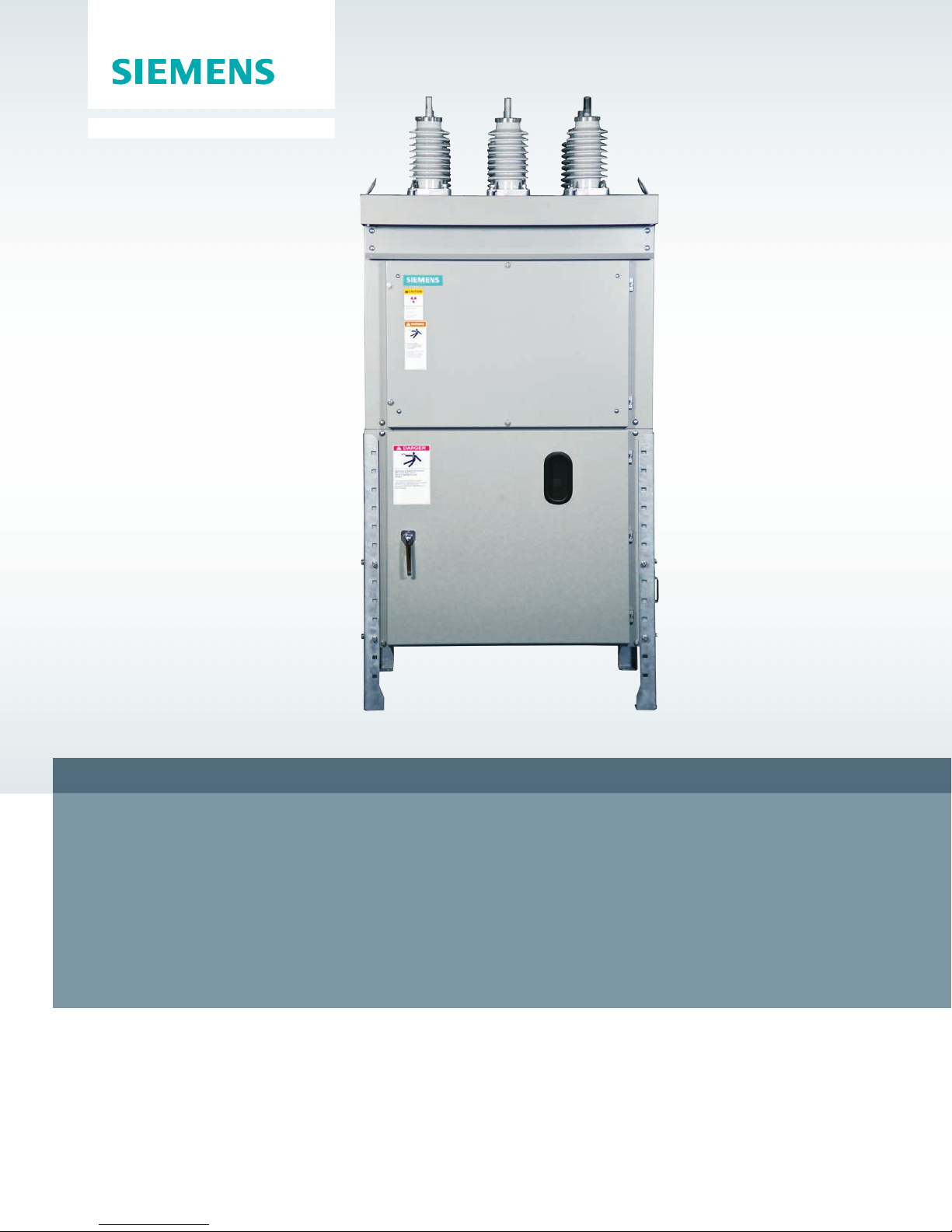
Type SDV7 non-arc-resistant distribution circuit breaker
Installation operation maintenance E50001-F710-K377-V6-4A00
www.usa.siemens.com/sdv7
Arc flash hazard and hazardous voltages.
Will cause death, serious injury or property damage.
Always de-energize and ground the equipment before maintenance.
Read and understand this instruction manual before using
equipment. Maintenance should be performed only by qualified
personnel. The use of unauthorized parts in the repair of the
equipment or tampering by unqualified personnel will result in
dangerous conditions which will cause death, severe injury or
equipment damage. Follow all safety instructions contained herein.
Important
The information contained herein is general in nature and not
intended for specific application purposes. It does not relieve the
user of responsibility to use sound practices in application,
installation, operation and maintenance of the equipment
purchased. Siemens reserves the right to make changes in the
specifications shown herein or to make improvements at any
time without notice or obligation. Should a conflict arise
between the general information contained in this publication
and the contents of drawings or supplementary material or
both, the latter shall take precedence.
Qualified person
For the purpose of this instruction manual a qualified person is one
who has demonstrated skills and knowledge related to the
installation, construction and operation of the equipment and the
hazards involved. In addition, this person has the following
qualifications:
Is trained and authorized to
de-energize, clear, ground and tag circuits and equipment in
accordance with established safety procedures.
Is trained in the proper care and use of protective equipment,
such as: rubber gloves, hard hat, safety glasses or face shields,
flash clothing, etc., in accordance with established safety
practices.
Is trained in rendering first aid.
Further, a qualified person shall also be familiar with the proper use
of special precautionary techniques, personal protective equipment,
insulation and shielding materials, and insulated tools and test
equipment. Such persons are permitted to work within limited
approach of exposed live parts operative at 50 volts or more, and
shall, at a minimum, be additionally trained in all of the following:
The skills and techniques necessary to distinguish exposed
energized parts from other parts of electric equipment
The skills and techniques necessary to determine the nominal
voltage of exposed live parts
The approach distances specified in NFPA 70E® and the
corresponding voltages to which the qualified person will be
exposed
The decision-making process necessary to determine the degree
and extent of the hazard and the personal protective equipment
and job planning necessary to perform the task safely.

Note:
These instructions do not purport to cover all
details or variations in equipment, nor to
provide for every possible contingency to be
met in connection with installation, operation
or maintenance. Should further information be
desired or should particular problems arise
that are not covered sufficiently for the
purchaser’s purposes, the matter should be
referred to the local sales office.
Table of contents
Introduction 04 – 05
General description 06 – 07
Receiving, handling and storage 08 – 10
Installation 11 – 13
Electrical connections 14
Instrument transformers 15 – 16
The contents of this instruction manual shall
not become part of or modify any prior or
existing agreement, commitment or
relationship. The sales contract contains the
entire obligation of Siemens Industry, Inc. The
warranty contained in the contract between
the parties is the sole warranty of Siemens
Industry, Inc. Any statements contained herein
do not create new warranties or modify the
existing warranty.
Installation of type SDV7-SE distribution circuit breaker
with stored-energy operator 17 – 24
Installation of type SDV7-MA distribution circuit breaker
with magnetic-actuator operator 25 – 34
Maintenance 35 – 42
Maintenance and troubleshooting 43 – 47
Appendix 48 – 55
Introduction
Arc flash hazard and hazardous voltages.
Will cause death, serious injury or property damage.
Always de-energize and ground the equipment before maintenance. Read
and understand this instruction manual before using equipment.
Maintenance should be performed only by qualified personnel. The use of
unauthorized parts in the repair of the equipment or tampering by
unqualified personnel will result in dangerous conditions which will cause
death, severe injury or equipment damage. Follow all safety instructions
contained herein.
Arc flash hazard, hazardous voltages and high-speed moving parts.
Will cause death, serious injury or property damage.
To avoid arc flash burns, electrical shock and entanglement in moving parts,
only qualified personnel should work on or around this equipment after
becoming thoroughly familiar with all danger or warning notices, and
procedures contained herein. Personnel must observe all applicable
regulations (e.g., OSHA), follow all requirements of NFPA 70E and adhere to
specific operating procedures applicable to the installation. Use appropriate
personal protective equipment (PPE) for the voltage and arc flash incident
energy exposure.
4

Introduction
The type SDV7 distribution circuit breaker is
designed to meet all applicable ANSI, NEMA
and IEEE standards. Successful application
and operation of this equipment depends as
much upon proper installation and
maintenance by the user as it does upon the
proper design and fabrication by Siemens.
The purpose of this instruction manual is to
assist the user in developing safe and
efficient procedures for the installation,
maintenance and use of the equipment.
This instruction manual applies to the type
SDV7 distribution circuit breaker enclosure,
including the type SDV7-SE model with
stored-energy operator and the type SDV7MA model with magnetic-actuator operator.
Refer to instruction manual E50001-F710K376-X-XXXX for instructions applicable to
the type 3AH35-SE stored-energy operator
used in the type SDV7-SE circuit breaker.
Refer to instruction manual E50001-F710K378-X-XXXX for instructions applicable to
the type 3AH35-MA magnetic-actuator
operator used in the type SDV7-MA circuit
breaker.
Field service operation and warranty
issues
Siemens can provide competent, well-trained
field service representatives to provide
technical guidance and advisory assistance
for the installation, overhaul, repair and
maintenance of Siemens equipment,
processes and systems. Contact regional
service centers, sales offices or the factory for
details, or telephone Siemens field service at
+1 (800) 347-6659 or +1 (919) 365-2200
outside the U.S.
For medium-voltage customer service issues,
contact Siemens at +1 (800) 347-6659 or +1
(919) 365-2200 outside the U.S.
Contact the nearest Siemens representative
if any additional information is desired.
Signal words
The signal words “danger,” “warning” and
“caution” used in this manual indicate the
degree of hazard that may be encountered by
the user. These words are defined as:
Danger - Indicates an imminently hazardous
situation that, if not avoided, will result in
death or serious injury.
Warning - Indicates a potentially hazardous
situation that, if not avoided, could result in
death or serious injury.
Caution - Indicates a potentially hazardous
situation that, if not avoided, may result in
minor or moderate injury.
Notice - Indicates a potentially hazardous
situation that, if not avoided, may result in
property damage.
5
General description
The instructions included in this instruction
manual are provided to aid you in obtaining
longer and more economical service from
your Siemens type SDV7 distribution circuit
breaker. For proper installation and operation,
this information should be distributed to your
operators and engineers.
By carefully following these instructions,
difficulties should be avoided. However, these
instructions are not intended to cover all
details of variations that may be encountered
in connection with the installation, operation
and maintenance of this equipment.
Should additional information be desired,
including replacement instruction manuals,
contact your local Siemens representative.
Scope
These instructions cover the installation,
operation and maintenance of Siemens type
SDV7 distribution circuit breaker using
vacuum interrupters. The equipment designs
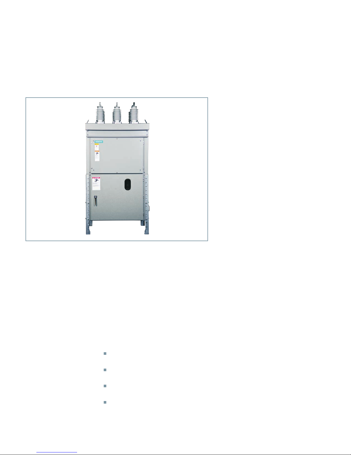
Figure 1: Typical type SDV7 distribution circuit breaker
Introduction
Siemens type SDV7 distribution circuit
breaker is precision built equipment designed
to function efficiently under normal operating
conditions. It is designed and manufactured
to operate within the parameters established
in ANSI/IEEE C37 and NEMA standards for
distribution circuit breakers. Performance
requirements of these standards have been
met or exceeded by these designs. Specific
standards which apply include:
ANSI/IEEE C37.04-1999 rating structure
for ac high-voltage circuit breakers
ANSI/IEEE C37.06-2009 preferred ratings
ac high-voltage circuit breakers
ANSI/IEEE C37.09-1999 test procedure for
ac high-voltage circuit breakers
NEMA SG4-2009 ac high-voltage circuit
breakers.
described in this instruction manual consists
of free-standing outdoor distribution circuit
breakers for application up to 38 kV. A typical
type SDV7 distribution circuit breaker is
shown in Figure 1: Typical type SDV7
distribution circuit breaker. All diagrams,
descriptions and instructions apply to all of
the above classes and designs unless noted
otherwise.
Standard construction details of the circuit
breaker enclosure are given in appropriate
sections of this instruction manual.
Standard construction details of the storedenergy operating mechanism of the circuit
breaker are detailed in the type 3AH35-SE
stored-energy operator instruction manual
E50001-F710-K376-X-XXXX.
Standard construction details of the
magnetic-actuator operating mechanism of
the circuit breaker are detailed in the type
3AH35-MA magnetic-actuator operator
instruction manual E50001-F710-K378-XXXXX.
6

Special mechanical and electrical devices,
furnished in accordance with purchase order
requirements, are covered by supplementary
instructions submitted with this instruction
manual.
The equipment furnished has been designed
to operate in a system having the circuit
capacity specified by the purchaser. If for any
reason the equipment is used in a different
system or if the short-circuit capacity of the
system is increased, the ratings of the
equipment, including the momentary rating
and the interrupting capacity of the type
SDV7 distribution circuit breaker must be
checked. Failure on the part of the user to
receive approval of intended changes from
Siemens may cause the warranty to be void.
This instruction manual applies to the type
SDV7 distribution circuit breaker enclosure
structure.
Refer to instruction manual E50001-F710K376-X-XXXX for instructions applicable to
the type 3AH35-SE stored-energy operator.
Refer to instruction manual E50001-F710K378-X-XXXX for instructions applicable to
the type 3AH35-MA magnetic-actuator
operator.
General description
The distribution circuit breaker described in
this instruction manual is of the ac highvoltage outdoor circuit breaker type, as
defined in ANSI/IEEE C37 and NEMA SG4
standards. All high-voltage parts excluding
roof bushings are completely enclosed within
grounded barriers. The secondary control
devices and primary circuits are isolated from
each other by barriers.
Siemens type SDV7 distribution circuit
breakers carry a type designation, as shown
in Table 1: Type SDV7 distribution circuit
breaker designations. This designation may
appear on drawings and familiarity with them
will simplify communications with the
factory.
In this instruction manual, reference to type
SDV7 distribution circuit breaker is used when
the text applies to the circuit breaker with
either type of operating mechanism. When
relevant to the type of operator, the type
SDV7-SE (stored-energy) or type SDV7-MA
(magnetic-actuator) designations are used.
Operator Type
Stored energy SDV7-SE
Magnetic actuator SDV7-MA
Table 1: Type SDV7 distribution circuit breaker
designations
7

Receiving, handling
and storage
Receiving
Each type SDV7 distribution circuit breaker is
securely blocked and braced for shipment. It
is crated, boxed or covered as required by
shipping conditions. If special handling is
required, it is so indicated. Relatively delicate
instruments, protective relays and other
devices are included, and the type SDV7
distribution circuit breaker must be handled
carefully when unloading.
Inspection and unpacking
Inspect the equipment as soon as possible
after receipt for any damage that may have
occurred in transit. Before unpacking,
examine the package itself, as a damaged
package may indicate damage to the contents
of the package. Be careful when unpacking
equipment. The use of sledge hammers and
crowbars may damage the finish, or the
equipment itself. Use nail pullers. After
unpacking, examine equipment for any
possible damage. Check the shipping
manifest to be certain that all items have
been received.
Note: If there is a shortage, make certain it is
noted on the freight bill and contact the
carrier immediately. Notify Siemens mediumvoltage customer service at +1 (800) 3476659 (+1 (919) 365-2200 outside the U.S.) of
any shortage or damage.
1. When shipment arrives, note whether
equipment is properly protected from the
elements. Note trailer number on which
the equipment arrived. Note blocking of
equipment. During unloading, make sure
to count the actual items unloaded to
verify the contents as shown on the
delivery receipt.
2. Make immediate inspection for visible
damage upon arrival and prior to
disturbing or removing packaging or
wrapping material. This should be done
prior to unloading when possible. When
total inspection cannot be made on
vehicle prior to unloading, close
inspection during unloading must be
performed and visible damage noted on
the delivery receipt. Take pictures if
possible.
3. Any visible damage must be noted on the
delivery receipt and acknowledged with
the driver’s signature. The damage should
be detailed as much as possible. It is
essential that a notation “possible internal
damage, subject to inspection” be
included on delivery receipt. If the driver
will not sign the delivery receipt with
damage noted, the shipment should not
be signed for by the consignee or their
agent.
Shipping damage claims
Important: The manner in which visible
shipping damage is identified by consignee
prior to signing the delivery receipt can
determine the outcome of any damage claim
to be filed.
Notification to carrier within 15 days for
concealed damage is essential if loss resulting
from unsettled claims is to be eliminated or
minimized.
8
4. Notify Siemens immediately of any
damage, at +1 (800) 347-6659 or +1
(919) 365-2200 outside the U.S.
5. Arrange for a carrier inspection of damage
immediately.

Important: Do not move equipment from the
place it was set when unloading. Also, do not
remove or disturb packaging or wrapping
material prior to carrier damage inspection.
Equipment must be inspected by carrier prior
to handling after receipt. This eliminates loss
due to claims by carrier that equipment was
damaged or further damaged on site after
unloading.
6. Be sure equipment is properly
protected from any further damage by
covering it properly after unloading.
7. If practical, make further inspection for
possible concealed damage while the
carrier’s inspector is on site. If inspection
for concealed damage is not practical at
the time the carrier’s inspector is present,
it must be done within 15 days of receipt
of equipment. If concealed damage is
found, the carrier must again be notified
and inspection made prior to taking any
corrective action to repair. Also notify
Siemens immediately at +1 (800) 3476659 or +1 (919) 365-2200 outside the
U.S.
Note: Shipments are not released from the
factory without a clear bill of lading.
Approved methods are employed for
preparation, loading, blocking and tarping
of the equipment before it leaves the
Siemens factory. Any determination as to
whether the equipment was properly loaded
or properly prepared by shipper for over-theroad travel cannot be made at the
destination. If the equipment is received in a
damaged condition, this damage to the
equipment has to have occurred while en
route due to conditions beyond Siemens
control. If the procedure outlined above is
not followed by the consignee, purchaser or
their agent, Siemens cannot be held liable
for repairs. Siemens will not be held liable
for repairs in any case where repair work
was performed prior to authorization from
Siemens.
8. Obtain the original of the carrier
inspection report and forward it along
with a copy of the noted delivery receipt
to Siemens at +1 (800) 347-6659 or +1
(919) 365-2200 outside the U.S. Approval
must be obtained by Siemens from the
carrier before any repair work can be
performed. Before approval can be
obtained, Siemens must have the above
referenced documents. The carrier
inspection report and/or driver’s signature
on the delivery receipt does not constitute
approval to repair.
9
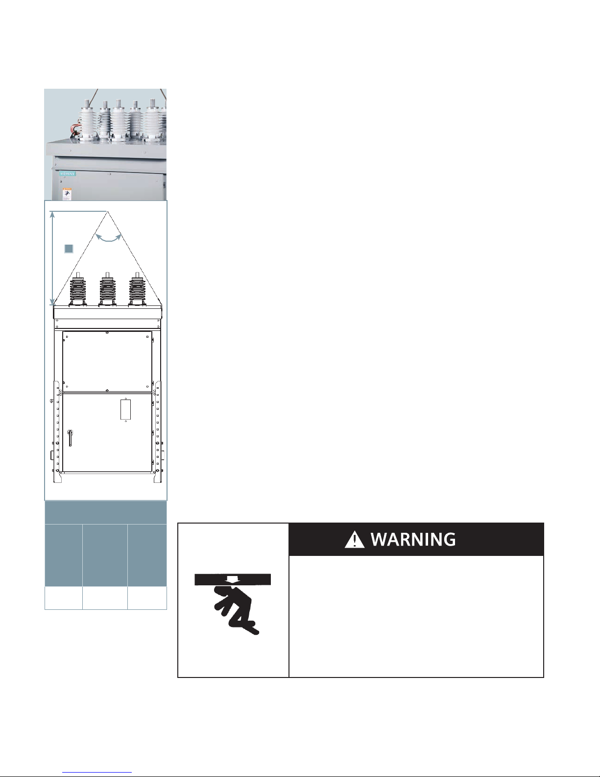
Lifting and moving
There are a number of methods that can be
used in handling the type SDV7 distribution
circuit breaker that, when properly
employed, will not damage the type SDV7
distribution circuit breaker. The handling
method used will be determined by
conditions and available equipment at the
installation site. Lifting with a crane by the
use of a sling and lifting lugs is the preferred
method of handling; however, overhead
obstructions often dictate that other
methods must be used. Forklift trucks may
A
~60°
be used prior to removal of wooden skids.
Verify the forklift blades pass completely
through the wooden skid under the circuit
breaker.
Each type SDV7 distribution circuit breaker
has provisions for attaching lifting cables.
Lifting lugs are provided on two sides of the
circuit breaker, which are designed for use
with a lift sling or hooks of the proper size
and a crane of adequate height and
capacity. Refer to the type SDV7 distribution
circuit breaker nameplate for the weight.
Lifting type SDV7 distribution circuit
breaker with crane
Recommended lifting of type SDV7
distribution circuit breakers is by means of
cables connected to an overhead crane. The
cables are connected to the lifting lugs on
the top of the type SDV7 distribution circuit
breaker as illustrated in Figure 2: Lifting
type SDV7 distribution circuit breaker with
crane. A crane with sufficient height should
be used so the load angle on the lifting
cable will be approximately 60° when
viewed from the front or rear.
Storage
When it is necessary to store a type SDV7
distribution circuit breaker in an area
exposed to the weather or under humid
conditions, energize the space heaters
provided and make certain that any vents
are uncovered to allow air to circulate. If at
all possible, install the type SDV7
distribution circuit breaker at the permanent
location even though it may be some time
before the equipment is used. It is also
recommended that the type SDV7
distribution circuit breaker receive periodic
inspection during storage.
dimensions in inches (mm)
15.5 kV,
1,200 A2,000 A
41
(1,040)
distribution circuit breaker with
Value A
15.5 kV
3,000 A
and
27.6 kV
1,200 A-
2,000 A
48
(1,220)
Figure 2: Lifting type SDV7
38.0 kV,
1,200 A2,500 A
(1,550)
61
crane
Access to the heater circuit is gained by
opening the door to the relay and control
compartment. Refer to the wiring diagram
drawing for space heater circuit
connections. Lubricate hinges and other
moving parts.
Heavy weight.
Can result in death, serious injury or property damage.
Observe all handling instructions in this instruction manual to prevent
tipping or dropping of equipment.
10

Installation
Preparation for installation
Prior to installation of the type SDV7
distribution circuit breaker, careful design,
planning and construction of the foundation
or base on which the circuit breaker will rest
must be made. A thorough analysis and
careful construction may alleviate many
problems at the time of installation, and
during operation. It is important that a
relatively level surface be provided capable
of supporting the weight of the type SDV7
distribution circuit breaker, and 0.75 inch
diameter anchor bolts are recommended.
Figure 4: Anchoring type SDV7 distribution
circuit breaker on page 13 illustrates typical
locations for anchor bolts. No special
leveling procedures are required.
Prior to installation of a type SDV7
distribution circuit breaker, study this
instruction book and the circuit breaker
drawings, such as general arrangement/
outline drawing, schematic diagram,
connection diagrams, current transformer
connection diagram, electrical bill of
material and nameplate engraving.
Special attention should be given to the
foundation information contained in this
instruction manual as well as the
information provided on the equipment
drawings. Verify the foundation conforms to
the requirements described in this
instruction manual and the general
arrangement/outline drawing.
The type SDV7 distribution circuit breaker is
shipped with the legs attached. The legs
must be set to the desired height.
Setting leg height
The type SDV7 distribution circuit breaker is
shipped with the legs set to a low level (and
on some units, turned outward). The legs
must be removed and installed correctly.
Remove the legs from the enclosure. Raise
the enclosure, and install the legs at the
desired height.
The legs must be installed and turned
inward, so that the two sides of the each leg
are adjacent to the enclosure sides and the
hole at the bottom of the leg is inside the
perimeter of the enclosure, as in Figure 3:
Outline drawing on page 12.
Use anti-seize compound (Loctite* 77164 or
77124 nickel anti-seize) on the
stainless steel cap screws used to secure the
legs to facilitate removal of the legs should
it be required in the future.
The height (as installed) between the
mounting surface (foundation) and the
bottom of the enclosure must be at least 4”
(102 mm) and no higher than 28”
(711 mm).
High-seismic installations
Figure 3: Outline drawing on page 12 shows
optional cross-braces installed for highseismic requirements.
Cross braces can be installed if the bottom
of the enclosure is at least 12” (330 mm)
above the foundation.
The cross braces consist of steel links that
are adaptable for all installation heights
(from 13” (330 mm) to 28” (711 mm).
Install the cross braces as shown in the
illustration. The end of the link with a single
hole is bolted to the lowest hole on the leg.
The opposite link is bolted with the singlehole end bolted to one of the two highest
exposed holes in the leg below the
enclosure. The highest hole or second
highest hole is used, as necessary to allow
alignment. Then, bolt the two links together
towards the middle, using whichever set of
holes align.
When optional cross braces are furnished,
install all eight cross braces (four sets) to
obtain the required seismic performance.
Location
The circuit breaker should be located so that
it is readily accessible for manual operation
and inspection. Ample clearance should be
provided for doors and panels to swing
open, or to be removed for servicing the
circuit breaker.
1
/2-13 SAE
* Loctite is a registered
trademark of Henkel
Corporation.
11
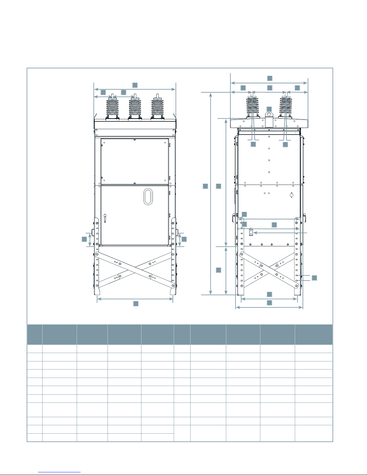
Figure 3: Outline drawing
1
Note 1: Shown with
optional cross-bracing
for high-seismic
loading, and with legs
installed at maximum
height 28" (711 mm).
Dimensions in inches
(mm)
A
B
C
E E
2-4-6 1-3-5
H
G
I
J
D
K
L
High-voltage
compartment
TU
Operator
compartment
M
N
Relay and
control
compartment
O
Ground
pads on
diagonally
opposite
corners
S
P
Note 1
Q
R
27.6 kV
1,200 A-
2,000 A
38.0 kV
1,200 A-
2,500 A
Item
15.5 kV
1,200 A-
2,000 A
15.5 kV
3,000 A
Note 1
27.6 kV
1,200 A-
2,000 A
F
38.0 kV
1,200 A-
2,500 A
Item
15.5 kV
1,200 A-
2,000 A
15.5 kV
3,000 A
A 47.1 (1,196) 56.3 (1,430) 56.3 (1,430) 65.7 (1,669) L 3.0° 3.0° 3.0° 3.0°
B 10.6 (269) 12.1 (307) 12.1 (307) 13.4 (340) M 35.8 (909) 44.2 (1,123) 44.0 (1,118) 55.6 (1,412)
C 13.0 (330) 16.0 (406) 16.0 (406) 19.5 (495) N 7.6 (193) 7.7 (196) 7.6 (193) 9.5 (241)
D 2.0 (51) 2.0 (51) 2.0 (51) 2.0 (51) O 28.4 (721) 36.5 (927) 36.4 (925) 46.1 (1,171)
E 8.0 (203) 8.0 (203) 8.0 (203) 8.0 (203) P 3.0 (76) 3.0 (76) 3.0 (76) 3.0 (76)
F 42.7 (1,085) 52.0 (1,321) 52.0 (1,321) 63.1 (1,603) Q 31.3 (795) 39.4 (1,001) 39.4 (1,001) 50.9 (1,293)
G 44.5 (1,130) 57.8 (1,468) 49.6 (1,260) 63.2 (1,605) R 38.8 (986) 47.0 (1,194) 46.8 (1,189) 58.4 (1,483)
H 8.0 (203) 18.4 (467) 11.5 (292) 20.4 (518) S
4.0 (102)-
28.0 (711)
4.0 (102)-
28.0 (711)
4.0 (102)-
28.0 (711)
4.0 (102)-
28.0 (711)
I 19.8 (503) 21.0 (307) 21.0 (307) 22.2 (564) T 73.5 (1,867) 77.2 (1,961) 77.6 (1,971) 93.5 (2,375)
J 8.0 (203) 18.4 (467) 11.5 (292) 20.4 (518)
K 3.0° 3.0° 3.0° 3.0°
U
92.0 (2,337)-
116.0 (2,945)
96.0 (2,337)-
120.0 (3,048)
96.0 (2,337)-
120.0 (3,048
120.5 (3,061)-
144.5 (3,670)
12
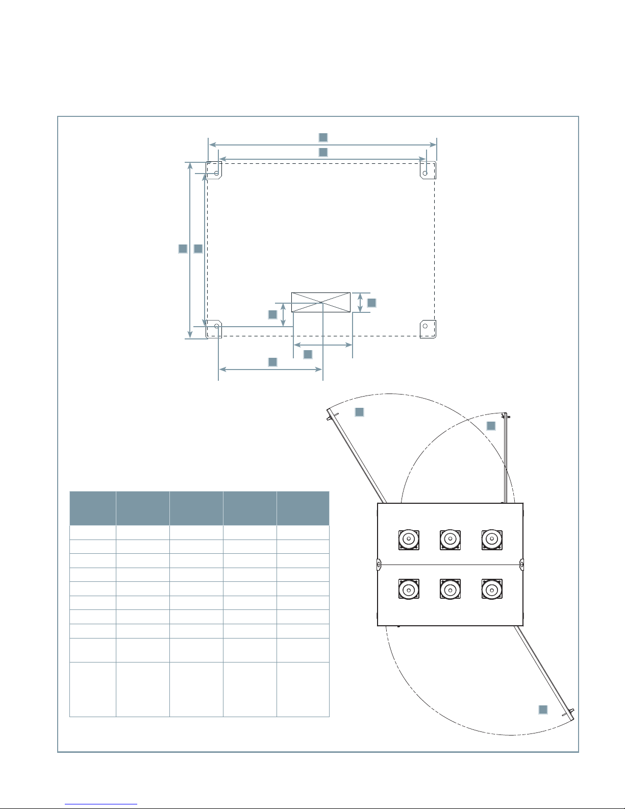
Figure 4: Anchoring type SDV7 distribution circuit breaker
A
B
GH
C
F
E
Dimensions in inches (mm)
Item
A 47.1 (1,196) 56.5 (1,435) 56.5 (1,435) 67.8 (1,722)
B 42.7 (1,085) 52.0 (1,321) 52.0 (1,321) 63.1 (1,603)
C 6.0 (152) 6.0 (152) 6.0 (152) 6.0 (152)
D 12.0 (305) 12.0 (305) 12.0 (305) 12.0 (305)
E 21.3 (541) 26.0 (660) 26.0 (660) 31.5 (800)
F 4.9 (124) 3.9 (99) 4.9 (124) 5.1 (130)
G 31.3 (795) 39.4 (1,001) 39.4 (1,001) 50.7 (1,288)
H 36.1 (917) 44.2 (1,123) 44.2 (1,123) 55.6 (1,412)
I (Outer
door)
J (Inner
relay
panel,
when
supplied)
15.5 kV
1,200 A-
2,000 A
40.0 (1,016) 46.5 (1,181) 46.5 (1,181) 46.8 (1,189)
36.0 (914) 42.8 (1,087) 42.8 (1,087) 41.3 (1,049)
15.5 kV
3,000 A
27.6 kV
1,200 A-
2,000 A
D
38.0 kV
1,200 A-
2,500 A
I
I
J
J
I
I
13
Electrical connections
Hazardous voltages and high speed moving parts.
Will cause death, serious injury or property damage.
Do not work on energized equipment. Always de-energize and ground highvoltage conductors before working on or near them. The user must adjust
the circuit breaker height to ensure compliance with safety codes for
electrical clearance.
14
Primary lead connections
The primary leads must be routed to the
bushing terminals so as to maintain
adequate dielectric clearance between
different phase conductors and to ground.
Conductors must be supported so that the
circuit breaker bushings are not subjected to
excessive strains, both during normal
service and in the event of a short-circuit
condition. The leads should be sized to have
a capacity at least equal to the maximum
operating current of the circuit and within
the rating of the type SDV7 distribution
circuit breaker. Connections are to be made
to the bolted terminals of the bushings and
must be securely tightened to a clean,
bright surface to assure good contact.
Ground connections
Grounding pads on diagonally opposite
corners of the enclosure are provided for
connecting the cabinet to ground. The
grounding conductors should be at least 4/0
AWG conductor on each ground pad. A good
low-resistance ground is essential for
adequate protection and for proper
functioning of electronic components such
as protective relays. Connections to ground
pads must be made in such a manner that a
reliable ground connection is obtained.
Consult latest National Electrical Code® or
National Electric Safety Code® for ground
connection standards.
Secondary control wiring
All secondary control wiring installed by the
factory is neatly routed and secured in
place. Complete all field connections in a
similar manner. Check that the protective
relay panel (if so equipped) clears any
additional wiring installed.
A conduit panel opening is provided in the
bottom of the relay and control
compartment for the connection of control
circuits. The control wires should be run
separately from high-voltage wiring to
prevent inductive coupling between them
and should be sized for full operating
current to avoid a drop in voltage below that
specified on the nameplate. All conduits
should be sealed off at their entrance to the
relay and control compartment.
Terminal blocks are provided inside the relay
and control compartment for the
connections necessary for the control wiring
and protective relay panel (if so equipped).
Terminal blocks for current transformer
wiring are located in the operator
compartment and wires can easily be routed
from the conduit panel opening in the relay
and control compartment to the current
transformer circuit terminal blocks in the
operator compartment. Consult the
connection diagrams for the location of
connection terminal points for each circuit.
Connection diagrams are provided with
each type SDV7 distribution circuit breaker
and will be found in the pocket inside the
relay and control compartment door.
Instrument
transformers
Hazardous voltages.
Will cause death, serious injury or property damage.
Do not operate current transformers with the secondary open circuited.
Current transformers must be either connected to a load or short circuited.
Current transformer secondary circuits also must be grounded.
Current transformers (CTs)
Figure 5: Type SDV7 distribution circuit
breaker with interphase barriers and
bushing current transformers installed in
primary compartment on page 16 illustrates
bushing (toroidal) CTs installed in the
primary compartment of a type SDV7
distribution circuit breaker. The roof
bushings pass through the CTs. Up to two
CTs may be mounted around each roof
bushing. The bushing CT connections are
wired to separate terminal blocks located in
the low-voltage operator compartment.
Phase barriers
Phase barriers are provided on all 27.6 kV
and 38 kV class type SDV7 distribution
circuit breakers as shown in Type SDV7
distribution circuit breaker with interphase
barriers and bushing current transformers
installed in primary compartment on page
16. These plates of insulating material are
attached to the circuit breaker housing and
provide suitable electrical insulation
between the vacuum interrupter primary
circuits.
15
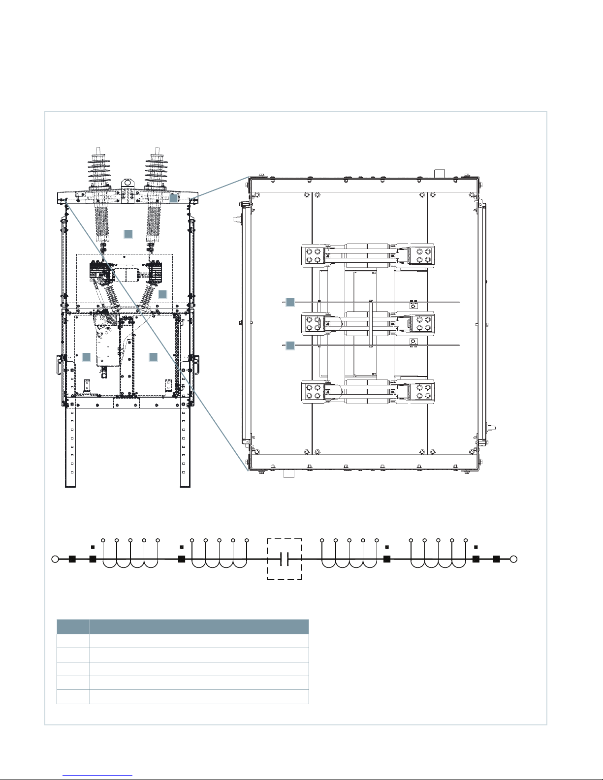
Figure 5: Type SDV7 distribution circuit breaker with interphase barriers and bushing current transformers installed in primary compartment
2-4-6 1-3-5
A
E
Bushings
2-4-6
B
B
B
D C
Vacuum
interrupter
X1 X2 X3 X4 X5 X1 X2 X3 X4 X5 X5 X4 X3 X2 X1 X5 X4 X3 X2 X1
X XY Y
Current transformer positions Current transformer positions
Bushings
1-3-5
Item Description
A Bushing current transformer (one per bushing shown)
B Phase barriers apply only in 27.6 kV and 38 kV
C Relay and control compartment
D Operator compartment
E High-voltage compartment
16
Note: Arrangement shown with four sets of multi-ratio
current transformers (five-lead type). Consult drawings for
the specific quantity and location of current transformers on
your circuit breaker.
Installation of type
SDV7-SE circuit
breaker with storedenergy operator
Hazardous voltages and high speed moving parts.
Will cause death, serious injury or property damage.
Read instruction manuals, observe safety instructions and use qualified
personnel.
Introduction
This section provides a description of the
inspections, checks and tests to perform on
the type SDV7-SE distribution circuit breaker
prior to operation.
Inspections, checks and tests without
control power
Type SDV7-SE vacuum circuit breakers are
normally shipped with the primary contacts
open and the springs discharged. However,
prior to starting the inspection process, it is
critical to first verify that the control power
is de-energized, the spring-loaded
mechanisms are in the discharged condition
and the circuit breaker main contacts are
open.
De-energizing control power in a power
circuit breaker
To de-energize the control power, open the
disconnect device in the relay and control
compartment. Figure 6: Relay and control
and operator compartments for type
SDV7-SE circuit breaker with stored-energy
operator on page 19 presents the location
of this disconnect in a standard type
SDV7-SE distribution circuit breaker.
The disconnect means shown in the photo
are knife switches with fuses. Molded-case
circuit breakers or pullout type fuse holders
can be furnished instead when specified.
The control power disconnect device is
located on the control panel in the relay and
control compartment.
17
 Loading...