

Page 1
15.5kV, 25.8kV and 27.6kV
Power Circuit Breaker
Type SDV-4A
Instructions
Installation
Operation
Maintenance
SGIM-3788F
Page 2
Hazardous voltages and high-speed moving parts.
Will cause death, serious injury or property damage.
Always de-energize and ground the equipment before
maintenance. Read and understand this instruction
manual before using equipment.
Maintenance should be performed only by qualified
personnel. Use only Siemens parts in the repair of the
equipment. Do not allow tampering with the equipment. Follow all safety instructions contained herein.
IMPORTANT
The information contained herein is general in nature and not intended for
specific application purposes. It does not relieve the user of responsibility
to use sound practices in application, installation, operation, and maintenance of the equipment purchased. Siemens reserves the right to make
changes in the specifications shown herein or to make improvements at
any time without notice or obligations. Should a conflict arise between the
general information contained in this publication and the contents of drawings or supplementary material or both, the latter shall take precedence.
QUALIFIED PERSON
For the purpose of this manual a qualified person is one who is familiar
with the installation, construction or operation of the equipment and the
hazards involved. In addition, this person has the following qualifications:
(a) is trained and authorized to de-energize, clear, ground, and tag cir-
cuits and equipment in accordance with established safety practices.
(b) is trained in the proper care and use of protective equipment such as
rubber gloves, hard hat, safety glasses or face shields, flash clothing,
etc., in accordance with established safety practices.
(c) is trained in rendering first aid.
NOTE
These instructions do not purport to cover all details or variations in equipment, nor to provide for every possible contingency to be met in connection with installation, operation, or maintenance. Should further information be desired or should particular problems arise which are not covered
sufficiently for the purchaser’s purposes, the matter should be referred to
the local sales office. The contents of this instruction manual shall not become part of or modify any prior or existing agreement, commitment or
relationship. The sales contract contains the entire obligation of Siemens
Power Transmission & Distribution Inc. The warranty contained in the contract between the parties is the sole warranty of Siemens Power Transmission & Distribution Inc. Any statements contained herein do not create new
warranties or modify the existing warranty.
Page 3
15.5kV, 25.8kV and 27.6kV Power Circuit Breaker
Table of Contents
Introduction and Safety ....................................................... 2
Introduction ............................................................................. 2
Qualified Person ...................................................................... 2
Signal Words ........................................................................... 2
Hazardous Procedures ............................................................ 2
Field Service Operation ........................................................... 2
General Description .............................................................. 3
Introduction ............................................................................. 3
Scope ...................................................................................... 3
General Description ................................................................ 3
Receiving, Handling & Storage ............................................ 4
Receiving ................................................................................ 4
Inspection ............................................................................... 4
Shipping Damage Claims ........................................................ 4
Lifting and Moving .................................................................. 5
Lifting Power Circuit Breaker with Crane ................................ 5
Storage .................................................................................... 5
Installation ............................................................................. 6
Location .................................................................................. 6
Preparation for Installation ...................................................... 6
“X” Bracing Installation Instructions
(for High Seismic Applications Only) ............................... 6
Foundation-General Requirements ......................................... 7
Electrical Connections .......................................................... 8
Primary Lead Connections ...................................................... 8
Ground Connections ............................................................... 8
Secondary Control Wiring ....................................................... 8
Instrument Transformers ..................................................... 9
Current Transformers .............................................................. 9
Installation Checks and Initial Functional Tests ............... 10
Introduction ........................................................................... 10
Inspections, Checks, And Tests Without Control Power ...... 10
Spring Discharge Check ........................................................ 10
Physical Inspections .............................................................. 11
Manual Spring Charging Check ............................................. 11
As-Found and Vacuum Check Tests ...................................... 11
Automatic Spring Charging Check ........................................ 11
Final Mechanical Inspection and
Testing Without Control Power ..................................... 11
Inspection ............................................................................. 11
Testing ................................................................................... 12
Interrupter/Operator Description ...................................... 13
Introduction ........................................................................... 13
Vacuum Interrupters ............................................................. 13
Stored Energy Operating Mechanism ................................... 13
Modes Of Operation - Discussion ......................................... 14
Spring Charging Mode .......................................................... 14
Closing Mode ........................................................................ 15
Trip Free Mode ...................................................................... 15
Opening Mode ...................................................................... 15
Rapid Auto-Reclosing Mode ................................................. 15
Closing And Tripping Springs ................................................ 15
Trip Free Operation ............................................................... 16
Damper ................................................................................. 16
Manual Spring Charging ........................................................ 16
Spring Charging Motor .......................................................... 17
Close Solenoid, Trip Solenoid and Anti-Pump Relay ............. 17
Auxiliary Switch ..................................................................... 17
Limit Switches ...................................................................... 17
Standard Schematic Diagrams .............................................. 17
Capacitor Trip Device (Optional) ............................................ 18
Maintenance ........................................................................ 21
Inspection and Maintenance Intervals .................................. 21
Recommended Hand Tools ................................................... 21
Recommended Maintenance and Lubrication ...................... 21
De-energize the Circuit Breaker ............................................ 22
Checks Of Primary Power Path ............................................ 22
Cleanliness Check ................................................................. 22
Checks of the Stored Energy Operator Mechanism ............. 23
Maintenance and Lubrication ................................................ 23
Fastener Check ..................................................................... 23
Manual Spring Charging And Contact Erosion Checks ......... 23
Vacuum Interrupter Stroke Check ......................................... 24
Damper Assembly Check ..................................................... 25
Electrical Control Checks ...................................................... 25
Check Of The Wiring And Terminals ..................................... 25
Automatic Spring Charging Check —
Control Power Required................................................ 25
Electrical Close And Trip Check —
Control Power Required................................................ 26
Checks Of Spring Charging Motor ........................................ 26
High Potential Tests .............................................................. 26
Vacuum Integrity Check ........................................................ 26
High Potential Test Voltages ................................................. 26
Vacuum Integrity Test Procedure .......................................... 27
As-Found Insulation and Contact Resistance Tests .............. 27
Insulation and Contact Resistance Test Equipment .............. 27
Insulation and Contact Resistance Test Procedure ............... 27
Inspection And Cleaning Of Breaker Insulation .................... 28
Functional Tests .................................................................... 28
Relays and Instruments ........................................................ 28
Equipment Surfaces .............................................................. 28
Operator Adjustments ........................................................ 29
Spring Charging Adjustment ................................................. 29
Spring Release Latch “Bite” Adjustment ............................. 30
Overhaul .............................................................................. 31
Introduction ........................................................................... 31
Circuit Breaker Overhaul ....................................................... 31
Replacement At Overhaul ..................................................... 31
Replacement Of Closing Springs .......................................... 31
Replacement Of Opening Spring .......................................... 32
Replacement Of Closing and Tripping Solenoids
(Devices 52SRC and 52T) ............................................. 32
Replacement of Anti-Pump Relay (Device 52Y) .................... 32
Replacement of the Auxiliary Switch .................................... 32
Replacement of Motor Cutoff Switch (Device LS1)
and Spring Charged Switch (LS2) ................................. 33
Replacement of Trip Latch Reset Check Switch
(Device LS3) .................................................................. 33
Replacement of Damper Assembly ...................................... 34
Replacement of Spring Charging Motor (Device 88) ............ 34
Replacement of Vacuum Interrupters ................................... 34
Index of Figures and Tables .................................................. 34
Recommended Hand Tools ................................................... 34
Preparation ............................................................................ 35
Vacuum Interrupter Removal ................................................ 35
Vacuum Interrupter Replacement ......................................... 35
Periodic Maintenance and Lubrication Tasks ................... 39
Troubleshooting .................................................................. 40
Ordering Replacement Parts ................................................. 42
Appendix .............................................................................. 43
Cover 2074-98
1
Page 4
Introduction and Safety
Introduction
The SDV (generic family name for SDV-4A) vacuum breakers are designed to meet all applicable ANSI, NEMA, and
IEEE standards. Successful application and operation of
this equipment depends as much upon proper installation
and maintenance by the user as it does upon the careful
design and fabrication by Siemens.
The purpose of this instruction manual is to assist the user
in developing safe and efficient procedures for the installation, maintenance and use of the equipment.
Contact the nearest Siemens representative if any additional
information is desired.
Hazardous voltages and high-speed moving
parts.
Will cause death, serious injury or property
damage.
To avoid electrical shock, burns and entanglement in moving parts this equipment must be
installed, operated and maintained only by
qualified persons thoroughly familiar with the
equipment, instruction manuals and drawings.
Read and understand this instruction manual
before using equipment.
Qualified Person
For the purpose of this manual a Qualified Person is one
who is familiar with the installation, construction or operation of the equipment and the hazards involved. In addition, this person has the following qualifications:
Caution - indicates a potentially hazardous situation which,
if not avoided, may result in minor or moderate injury.
Caution (without safety alert symbol) - indicates a potentially hazardous situation which, if not avoided, may result in property damage.
Hazardous Procedures
In addition to other procedures described in this manual
as dangerous, user personnel must adhere to the following:
1. Always work only on a de-energized breaker. The breaker
should be isolated, grounded, and have all control power
removed before performing any tests, maintenance or
repair.
2. Always perform maintenance on the breaker after the
spring-charged mechanisms are discharged (except for
test of the charging mechanisms). Check to be certain
that the indicator flags read OPEN and DISCHARGED.
3. Always let an interlock device or safety mechanism perform its function without forcing or defeating the device.
Field Service Operation
Siemens can provide competent, well-trained Field Service
Representatives to provide technical guidance and advisory assistance for the installation, overhaul, repair and
maintenance of Siemens equipment, processes and systems. Contact regional service centers, sales offices or the
factory for details, or telephone Siemens Field Service at
1-877-742-3309.
• Training and authorization to energize, de-energize, clear,
ground and tag circuits and equipment in accordance
with established safety practices.
• Training in the proper care and use of protective
equipment such as rubber gloves, hard hat, safety
glasses, face shields, flash clothing, etc., in accordance
with established safety procedures.
• Training in rendering first aid.
Signal Words
The signal words “Danger”, “Warning” and “Caution” used
in this manual indicate the degree of hazard that may be
encountered by the user. These words are defined as:
Danger - Indicates an imminently hazardous situation
which, if not avoided, will result in death or serious injury.
Warning - Indicates a potentially hazardous situation
which, if not avoided, could result in death or serious injury.
2
Page 5
General Description
The instructions included in this manual are provided to
aid you in obtaining longer and more economical service
from your Siemens Circuit Breakers. For proper installation and operation, this information should be distributed
to your operators, engineers and maintenance personnel.
By carefully following these instructions, difficulties should
be avoided. However, the instructions are not intended to
cover all details of variations that may be encountered in
connection with the installation, operation and maintenance
of this equipment.
Should additional information be desired, including replacement instruction books, contact your Siemens representative.
Scope
These instructions cover the installation, operation and
maintenance of Siemens type SDV power circuit breakers
using vacuum interrupters. The equipment described in
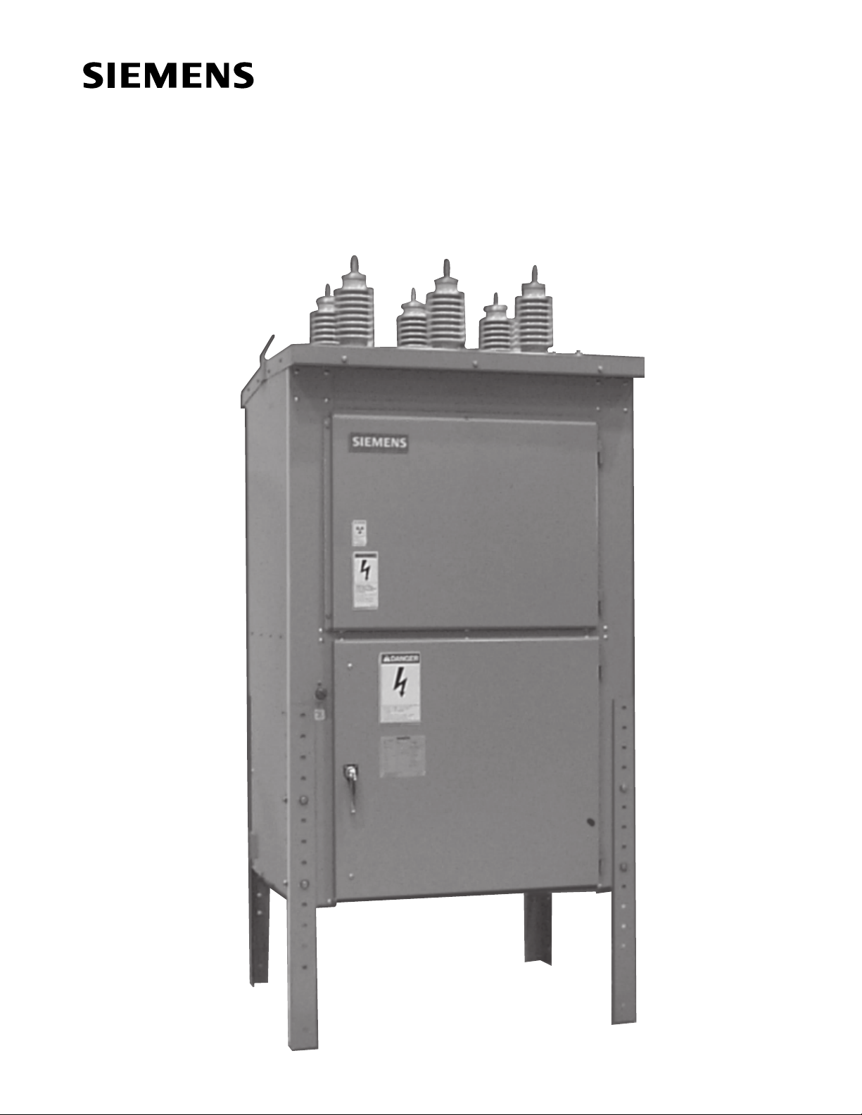
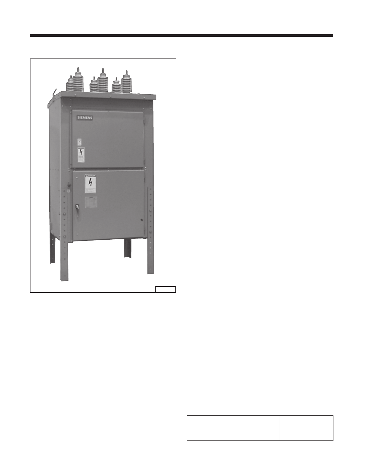
this manual consists of free standing outdoor power circuit breakers for application up to 27.6kV. A typical breaker
is shown in Figure 1. All diagrams, descriptions and instructions apply to all above types and designs unless noted
otherwise.
2075-98
Figure 1. Typical Power Circuit Breaker, Type SDV-4A.
Introduction
The successful performance and application of Power Circuit Breakers depends as much on proper installation,
maintenance and correct application as it does on good
design and careful manufacture .
Siemens Type SDV outdoor power circuit breakers are precision built units designed to function efficiently under
normal operating conditions. They are designed and manufactured to operate within the limits established in the ANSI
C37 and NEMA standards for Power Circuit Breakers. Performance requirements of these standards have been met
or exceeded by these designs. Specific Standards which
apply include:
Standard construction details of the circuit breaker are given
in the appropriate sections. Special mechanical and electrical devices, furnished in accordance with purchase order requirements, are covered by supplementary instructions submitted with this instruction manual.
The equipment furnished has been designed to operate in
a system having the circuit capacity specified by the purchaser. If for any reason the equipment is used in a different system, or if the short-circuit capacity of the system is
increased, the momentary rating and interrupting capacity
of the circuit breaker must be checked. Failure on the part
of the user to receive approval of intended changes from
Siemens may cause voiding the warranty.
General Description
The power circuit breaker described in this manual is the
AC high-voltage circuit breaker type, as defined in ANSI
C37 and NEMA SG 4. All high voltage parts excluding the
roof bushings are completely enclosed within grounded
metal barriers. Secondary control compartment and primary circuits are isolated from each other by barriers.
Siemens power circuit breakers carry a type designation
as shown in Table 1. This designation may appear on draw-
ings and familiarity with them will simplify communications with the factory.
C37.04 AC High-Voltage Circuit Breakers - Basis of Rating
C37.06 AC High-Voltage Circuit Breakers - Preferred Ratings
C37.09 AC High-Voltage Circuit Breakers - Test Code
SG 4 Alternating-Current High-Voltage Circuit Breakers
Table 1. Power Circuit Breaker Designation
DESIGN TYPE
Bolted Cabinet SDV-4A
3
Page 6

Receiving, Handling & Storage
Receiving
Each type SDV circuit breaker is securely blocked and
braced for shipment. Every precaution is taken to insure
its safe arrival. Relatively delicate instruments may be included and the circuit breakers must be handled carefully
when unloading and moving.
Inspection
Inspect the equipment as soon as possible after receiving
for any damage that may have occurred in transit. Before
unloading, make a physical inspection of the circuit breaker,
checking for shipment damage or indications of rough handling by the carrier. Check the shipping manifest to be certain that all items have been received. If there is a shortage, make certain it is noted on the freight bill and contact
the carrier immediately. Notify the Siemens sales office of
any shortage or damage.
Shipping Damage Claims
IMPORTANT: The way visible shipping damage is
treated by consignee prior to signing the delivery
receipt can determine the outcome of the damage
claim to be filed.
Notification to carrier within the 15 day limit on concealed
damage is essential if loss resulting from unsettled claims
is to be eliminated or minimized.
1. When shipment arrives, note whether equipment is
properly secured for transit. Note trailer number on
which the equipment arrived. Note blocking of
equipment. During unloading, make sure count agrees
with delivery receipt.
2. Make immediate inspection for visible damage upon
arrival, and prior to unloading. When total inspection
cannot be made on vehicles prior to unloading, close
inspection during unloading must be performed and
visible damage noted on the delivery receipt. Take
pictures if possible.
3. Any visible damage must be noted on the delivery receipt
and acknowledged with the driver’s signature. The
damage should be detailed as much as possible. It is
essential that a notation “Possible internal damage,
subject to inspection” be included on delivery receipt.
If the driver will not sign the delivery receipt with damage
noted, the shipment should not be signed for by the
consignee or his agent.
4. Notify the Siemens sales office immediately of any
damage.
5. Arrange for a carrier inspection of damage immediately.
IMPORTANT: Do not move equipment from the
place it was set when unloading. Equipment must
be inspected by carrier prior to handling after
receipt. This eliminates loss due to claims by carrier
that equipment was damaged or further damaged
on site after unloading.
6. Be sure equipment is properly protected from any further
damage by covering it properly after unloading.
7. If practical, make further inspection for possible
concealed damage while the carrier’s inspector is on
site. If inspection for concealed damage is not practical
at the time the carrier’s inspector is present, it must be
done within 15 days of receipt of equipment. If concealed
damage is found, the carrier must again be notified and
inspection made prior to taking any corrective action to
repair. Also notify Siemens sales office immediately.
8. Obtain the original of the carrier inspection report and
forward it along with a copy of the noted delivery receipt
to the Siemens sales office. Approval must be obtained
by Siemens from the carrier before any repair work can
be performed. Before approval can be obtained,
Siemens must have the documents. The carrier
inspection report and/or driver’s signature on the delivery
receipt does not constitute approval to repair.
Note: Any adverse judgment as to whether the equipment
was properly loaded or properly prepared by shipper for
over-the-road travel cannot be made at the destination.
Shipments are not released from the factory without a clear
bill of lading. Approved methods are employed for preparation, loading, blocking and securing of the equipment
before it leaves the Siemens factory. Therefore, if the equipment is received in a damaged condition, this damage to
the equipment had to occur while enroute due to conditions beyond Siemens control. If the procedure outlined
above is not followed by the consignee, purchaser, or his
agent, Siemens cannot be held liable for repairs. Siemens
will not be held liable for repairs in any case where the
work was performed prior to authorization from Siemens.
4
Page 7
Receiving, Handling & Storage
Heavy weight with a high center of gravity.
Can cause death, serious injury or property
damage.
Observe all handling instructions in this
instruction manual to prevent tipping or
dropping of equipment.
Lifting and Moving
There are a number of methods that can be used in handling the breaker, which when properly employed, will not
damage the breaker. The handling method used will be
determined by conditions and available equipment at the
installation site. Refer to the breaker nameplate for the
weight. Lifting with a crane by the use of sling and lifting
lugs is the preferred method of handling; however, overhead obstructions often dictate the method to be used. Fork
lift trucks may be used prior to removal of wooden skids.
Be sure that the forklift blades pass completely under the
breaker.
60.0"
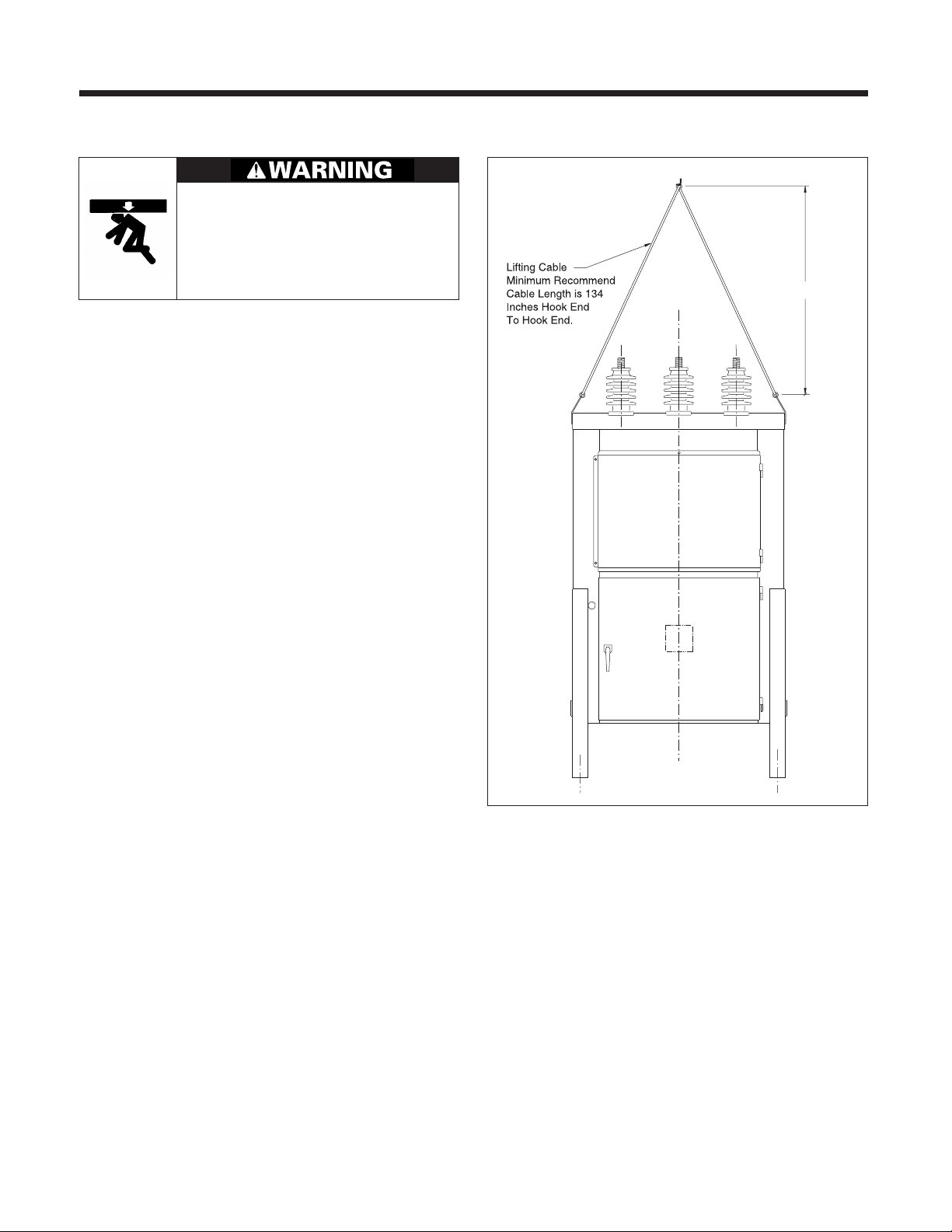
Refer to Figure 2 for lifting of the breaker using a sling.
Each power circuit breaker has provisions for attaching lifting cables. Lifting lugs are provided on each side of the
breaker, which are designed for use with a sling or hooks
of the proper size and a crane of adequate height and capacity. Refer to the breaker nameplate for the weight.
Lifting Power Circuit Breaker with Crane
Recommended lifting of power circuit breakers is by means
of cables connected to an overhead crane. The cables are
connected to the lifting lugs on the top of the breaker as
illustrated in Figure 2. A crane with sufficient height should
be used so the load angle (from horizontal) on the lifting
cable will be at least 63 degrees, when viewed from the
front or the rear. The minimum recommended cable length
to achieve proper load angle is 134 inches hook end to hook
end. A lesser angle (shorter cable) could cause damage to
the equipment.
Figure 2. Lifting Power Circuit Breaker - with Crane.
Storage
When it is necessary to store a power circuit breaker in an
area exposed to the weather or under humid conditions,
energize the space heaters provided and make certain that
any vents are uncovered to allow air to circulate. If at all
possible, install the breaker at the permanent location even
though it may be some time before the equipment is used.
It is also recommended that the breaker receive periodic
inspection during storage.
Access to the heater circuit is gained by opening the door
to the instrument panel compartment. Refer to wiring diagram drawing for space heater circuit connections. Lubricate hinges and other moving parts.
5
Page 8
Installation
Location
The breaker should be located so that it is readily accessible for manual operation and inspection. Ample clearance should be provided for doors and panels to swing
open, or to be removed for servicing the breaker.
Preparation for Installation
Prior to installation of a power circuit breaker, study this
instruction book and the breaker drawings, such as outline, CT diagram, elementary diagram, connection diagram,
relay panel diagram and electrical bill of material, and
nameplate engraving. Special attention should be given
to the foundation information contained in this manual as
well as the information provided on the equipment drawings. Be sure that the foundation conforms to the requirements described in this manual and the outline drawing.
SDV breakers are shipped with the legs positioned for shipment. The legs must be removed, turned to the proper
position and set to the desired height. Directions are given
in the notice decal.
“X” Bracing Installation Instructions (for High Seismic
Applications Only)
Once the SDV breaker is set in place at the correct height
with the legs correctly installed, “X” bracing must be added
to each of the four sides. Figure 3 shows appropriate installation for the breaker at its highest elevation. Other
breaker heights will use a similar configuration. The bracing is to run from the first hole below (nearest) the cabinet
on one leg to the bottom hole of the opposite leg. When
both braces are installed on any side of the breaker, they
form the letter “X”.
The bracing is to be attached to each leg using 1 set of 0.5
inch SAE Grade No. 5 hardware (torqued to 50-75 ft-lbs.).
The “X” bracing bars have a series of overlapping holes to
allow appropriate length adjustment. The two bars forming each brace will use 2 sets of 0.5 inch SAE Grade No. 5
hardware (torqued to 50-75 ft-lbs.) installed in the overlapping holes. Refer to Figure 3 for hardware requirements.
Figure 3. “X” Bracing Installation (High Seismic Applications Only).
6
Page 9
Installation
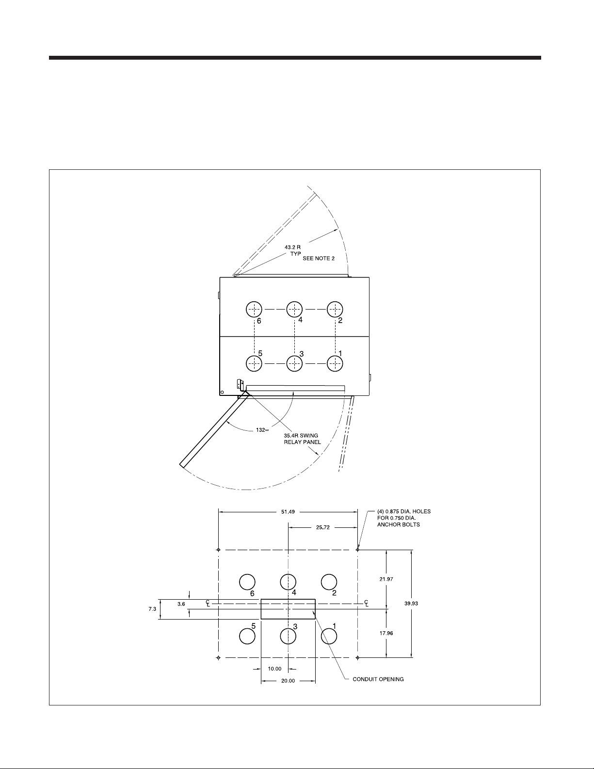
Foundation-General Requirements
Prior to installation of the breaker, careful design, planning
and construction of the foundation or base on which the
breaker will rest must be made. A thorough analysis and
careful construction may alleviate many problems at the
time of installation, and during operation. It is important
that a relatively level surface be provided capable of supporting the weight of the breaker, and 0.75 inch diameter
anchor bolts are recommended. Figures 4 illustrates typical locations for anchor bolts. No special leveling procedures are required.
Figure 4. Anchoring SDV-4A Power Circuit Breaker.
7
Page 10

Electrical Connections
Hazardous voltages.
Will cause death, serious injury, and
property damage.
De-energize and properly ground high
voltage conductors before working on or
near them. The user must adjust the breaker
height to ensure compliance with safety
codes for electrical clearance.
Primary Lead Connections
The primary leads should be brought down from above
the breaker if possible, with adequate clearance to other
parts, and with the proper supports so that the breaker
bushings are not subjected to excessive strains.
The leads should be sized to have a capacity at least equal
to the maximum operating current of the circuit and within
the rating of the breaker. Connections are to be made to
the bolted terminals of the bushings and must be securely
tightened to a clean, bright surface to assure good contact.
Ground Connections
Diagonally opposite grounding pads are provided for connecting the cabinet to ground, using at least a 4/0 AWG
conductor on each pad. A good low-resistance ground is
essential for adequate protection and for proper functioning of electronic components such as protective relays.
Provision for connecting to ground pads must be made in
such a manner that a reliable ground connection is obtained. Consult latest National Electrical Code or National
Electric Safety Code for ground connection standards.
Secondary Control Wiring
All secondary control wiring installed by the factory is neatly
routed and secured in place. Make all field connections in
a similar manner. Check that the relay panel (if so equipped)
clears any additional wiring installed.
A conduit panel opening is provided in the bottom of the
relay and control compartment for the connection of control circuits. The control wires should be run separately
from high voltage wiring to prevent inductive coupling
between them and should be sized for full operating current to avoid a drop in voltage below that specified on the
nameplate. All conduits should be sealed off at their entrance to the relay and control compartment.
Terminal blocks are provided inside the relay and control
compartment for the connections necessary for the control wiring, bushing current transformers and relay panel
(if so equipped). These terminal blocks are located inside
the control compartment immediately behind the control
compartment access door.
Connection diagrams are provided with each breaker and
will be found in the pocket inside the control compartment
door.
8
Page 11
Instrument Transformers
Current Transformers
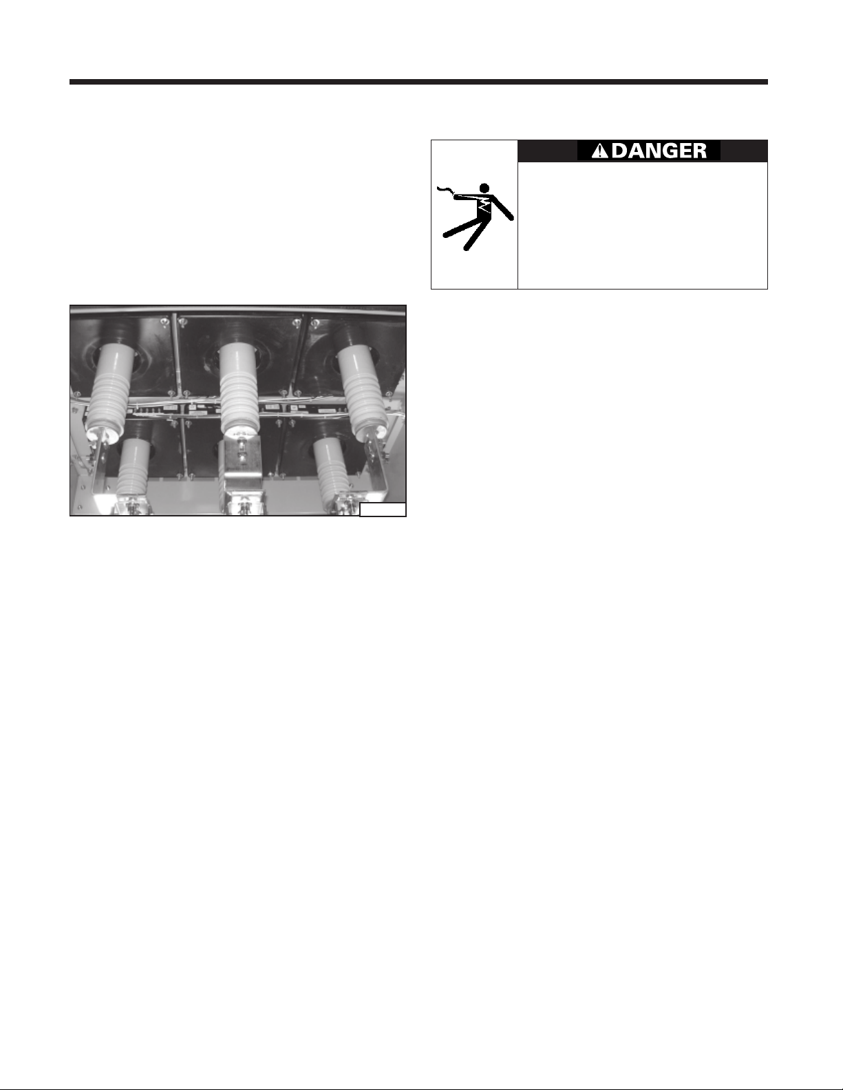
Figure 5 illustrates bushing (toroidal) current transformers
installed in the primary compartment of a circuit breaker.
The circuit breaker roof bushings pass through the transformers. Type BCM current transformers are of the toroidal type mounted in the circuit breaker primary compartment. Up to two current transformers may be mounted
around each roof bushing. The bushing current transformer
connections are wired to separate terminal blocks located
in the control and relay compartment.
Hazardous voltage.
Will cause death, serious injury, and
property damage.
Current Transformers must not be operated
with an open circuit and must be either
connected to a burden or short circuited and
grounded at the terminal blocks.
2088-98
Figure 5. Type BCM CT’s Installed in primary compartment.
View shown is looking up into cabinet roof
from below
9
Page 12
Installation Checks and Initial Functional Tests
Introduction
This section provides a description of the inspections,
checks and tests to perform on the circuit breaker prior to
operation.
Inspections, Checks, And Tests Without Control Power
Vacuum breakers are normally shipped with the primary
contacts open and the springs discharged. However, prior
to starting the inspection process, it is critical to
first
verify
that the control power is de-energized and the springloaded mechanisms are in the discharged condition.
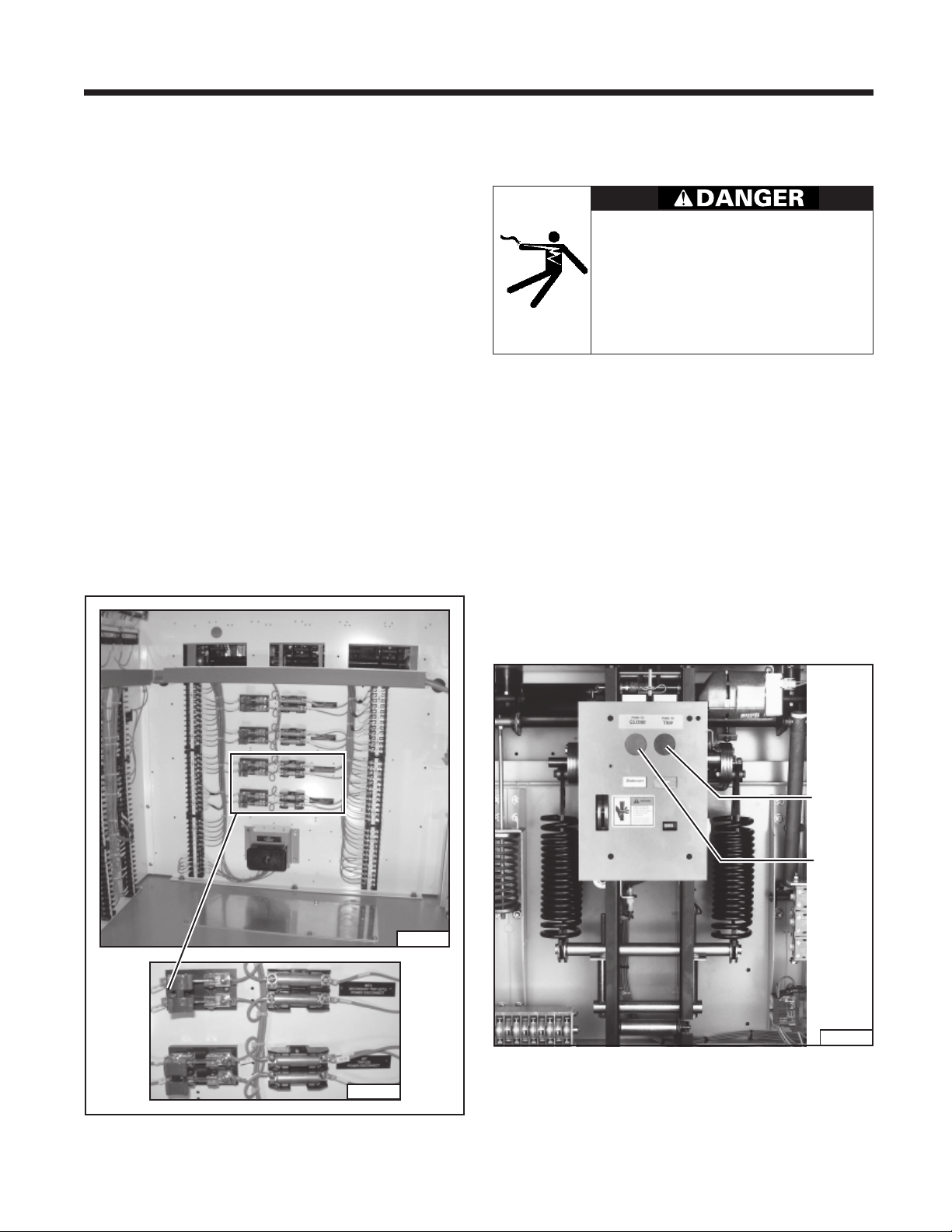
De-energizing Control Power in a Power Circuit Breaker To de-energize the control power, open the disconnect device in the secondary control compartment. Figure 6 shows
the location of this disconnect in a standard breaker.
The control power disconnect device is located on the control panel in the secondary control compartment. Figure 6
shows a knife switch with fuses. Opening the knife switch
de-energizes control power to the circuit breaker. In some
breakers pullout type fuse holders or molded case breakers are used in lieu of knife switches. Removal of the fuse
holder or opening the molded case breaker accomplishes
the same result: control power is disconnected.
Spring Discharge Check (Figure 7)
Hazardous voltages and high-speed
mechanical parts.
Will cause death, serious injury or property
damage.
Read instruction manuals, observe safety
instructions and use qualified personnel.
The spring discharge check consists of simply performing
the following tasks in the order given. This check assures
that both the tripping and closing springs are fully discharged.
1. De-energize control power.
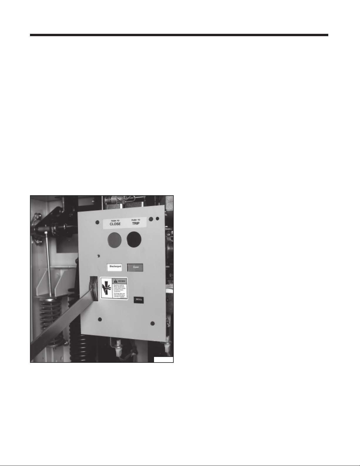
2. Press Trip pushbutton.
3. Press Close pushbutton.
4. Again press Trip pushbutton.
5. Verify Spring Condition Indicator shows DISCHARGED.
2078-98
6. Verify Main Contact Status Indicator shows OPEN.
Manual
Trip
Manual
Close
2082-98
Figure 7. Operator Control Panel of Power Circuit Breaker.
Figure 6.
2089-98
Control Power Disconnects in Power Circuit Breaker.
10
Page 13
Installation Checks and Initial Functional Tests
Physical Inspections
1. Verify that the rating of the circuit breaker is compatible
with the system.
2. Perform a visual shipping damage check. Clean the
breaker of all shipping dust, dirt and foreign material.
Manual Spring Charging Check
1. Insert the manual spring charging lever into the manual
charge handle socket as shown in Figure 8. Operate the
lever up and down until the spring condition indicator
shows the closing springs are Charged, and remove the
lever from the socket.
2. Repeat the Spring Discharge Check.
3. Verify that the springs are discharged and the breaker
primary contacts are open by observing the indicator
positions.
connected to the circuit breaker. (Refer to the specific wiring information and rating label for your circuit breaker to
determine the voltage required and where the control voltage signal should be applied.) When control power is connected to the breaker, the closing springs should automatically charge if the control power disconnect (see Figure 6)
is closed.
The automatic spring charging features of the circuit
breaker must be checked. Control power is required for
automatic spring charging to take place.
1. Use the manual Close and Trip controls (Figure 7) to first
Close and then Open the circuit breaker contacts. Verify
contact positions visually by observing the Open/Closed
indicator on the circuit breaker.
2. Open control power circuit by opening knife switch
shown in Figure 6.
3. Perform the Spring Discharge Check again. Verify that
the closing springs are discharged and the primary contacts of the circuit breaker are open.
Final Mechanical Inspection and Testing
Without Control Power
Before the circuit breaker is energized, it must be thoroughly
inspected and tested. Correct any deviations before
energization.
2090-98
Figure 8. Manual Charging of Closing Springs.
As-Found and Vacuum Check Tests - Perform and record
the results of both the As-Found insulation test and the
vacuum check high-potential test. Procedures for these
tests are described in the Maintenance Section of this
manual.
Automatic Spring Charging Check
Note: A temporary source of control power and test leads
may be required if the control power source has not been
Inspection
Check the following points:
1. Make a final mechanical inspection of the circuit breaker.
Verify that the contacts are in the Open position, and
the closing springs are Discharged.
2. Make sure the breaker is properly set up and reason-
ably level on its foundation and appropriately anchored
to the foundation.
3. Check the tightness of all hardware on the cabinet, ad-
justable legs, bushings, bus bars and operator mechanism.
4. See that the operating mechanism has been properly
lubricated.
5. Blocking, supports and other temporary ties removed
from breakers, instruments, relays, etc.
6. Proper fuses correctly placed.
7. Temporary wiring jumpers (used on the secondaries of
current transformers wired to external devices, as
shown on wiring diagrams) removed.
8. Ground connections properly made.
11
Page 14

Installation Checks and Initial Functional Tests
9. Incoming primary and secondary connections properly
made and checked for shorts or undesired grounds.
10. See that all covers, and bolted connectors are securely
fastened.
11. Relays coordinated with other relays and protection devices on the system. Refer to relay instructions before
making any adjustments.
12. Examine the vacuum interrupters for damage, and wipe
the interrupters and other insulating parts with a clean,
dry cloth.
13. All filters in vent areas are clean and free of shipping or
construction material.
14. Retouch any paint that has been damaged during installation.
Shipping bracing and tag between phase barriers (on units
so equipped) may damage circuit breaker.
May result in damage to equipment.
Remove bracing and tag (on units so equipped) before
energizing breaker high voltage.
Testing
High Potential tests employ hazardous
voltages.
Will cause death or serious injury.
Follow safe procedures, exclude unnecessary
personnel and use safety barriers. Keep away
from the breaker during application of test
voltages. After test completion, ground both
ends and the middle ring (if visible) of the
vacuum interrupter to dissipate any static
charges.
Note: No hazardous X-radiation is produced with closed
contacts, or with open contacts with rated operating voltage applied.
Excessive test voltages.
May result in damage to equipment.
Do not perform dielectric tests at test voltages exceeding the
ratings of the tested equipment.
1. An insulation resistance test is advisable on the control
circuit to be sure that all connections made in the field
are properly insulated.
2. A dielectric test, if possible, should be made on the high
voltage circuit for one minute at the following voltages
corresponding to the rated voltage of the equipment.
The voltage should be raised gradually and the circuit
under test should sustain the voltage for one minute.
When the test is performed with the breaker open, the
integrity of the vacuum interrupter will also be verified.
If these levels cannot be sustained and there is no other
source for the failure, the interrupter must be replaced.
Rated
Maximum
Voltage
kV (rms)
15.5
25.8, 27.6
Power
Frequency
Withstand
kV (rms)
50
60
Field Test Voltage
kV (rms) kV (dc)
37.5
45
53
63.6
Note: The DC test voltage is given as a reference only. It
represents values believed to be appropriate and approximately equivalent to the corresponding power frequency
withstand test values specified for each voltage rating. The
presence of this column in no way implies any requirement
for a DC withstand test on AC equipment or that a DC withstand test represents an acceptable alternative to AC withstand tests. When making DC tests, the voltage should be
raised to the test value in discreet steps and held for a period of one minute.
Vacuum interrupters may emit X-radiation.
Can cause serious injury.
X-rays can be produced when a high voltage
is placed across two circuit elements in a
vacuum.
Keep personnel more that six (6) feet away
from a circuit breaker under test. All normal
metallic doors and panels must be installed
during tests.
Field Dielectric Tests are recommended when new units
are installed, or after major field modifications. The equipment should be put in good condition prior to the field test.
It is not expected that equipment shall be subjected to these
tests after it has been stored for long periods of time or has
accumulated a large amount of dust, moisture, or other
contaminants without being first restored to good condition.
12
Page 15
Interrupter/Operator Description
Introduction
Type SDV circuit breakers include three vacuum interrupters, a stored energy operating mechanism and necessary
electrical controls. On some circuit breaker ratings, insulating barriers are located between the vacuum interrupters.
This section describes the operation of each major subassembly as an aid in the operation, installation, maintenance
and repair of the type SDV vacuum circuit breaker.
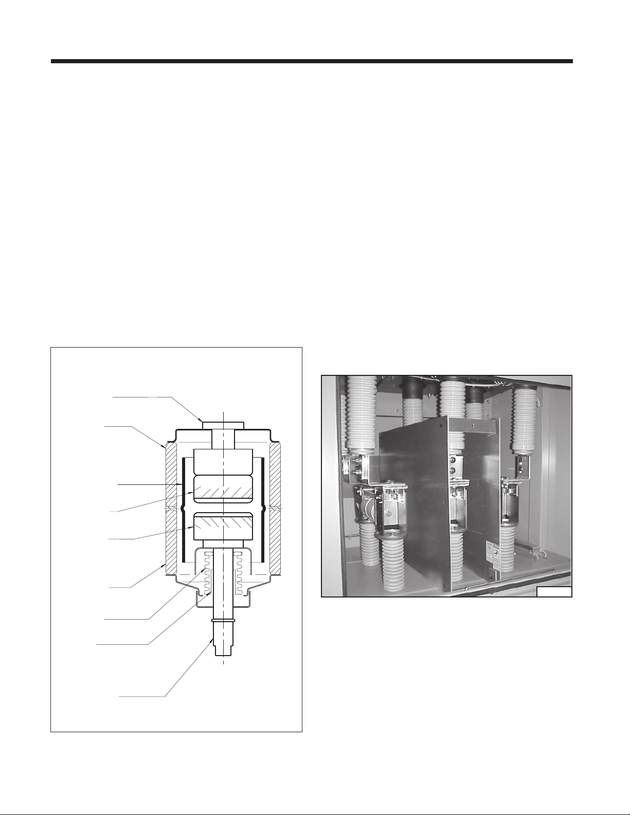
Vacuum Interrupters
The operating principle of the vacuum interrupter is simple.
Figure 9 is a cutaway view of a typical vacuum interrupter.
The entire assembly is sealed after a vacuum is established.
The interrupter stationary contact is rigidly attached to the
end cap which serves as one terminal of the interrupter.
The interrupter movable contact is free to move in a guide,
and is connected to the operating mechanism by a system
of linkages. The metal bellows assembly provides a secure seal around the movable contact, preventing loss of
vacuum while permitting movement of the contact.
Fixed
Contact
Current
Connection
When the two contacts separate, an arc is initiated which
continues conducting up to the following current zero. At
current zero, the arc extinguishes and any conductive metal
vapor which has been created by and supported the arc
condenses on the contacts and on the surrounding vapor
shield. Contact materials and configuration are optimized
to achieve arc motion and to minimize switching disturbances.
The arc drawn in the vacuum breaker is not cooled. The
metal vapor plasma is highly conductive and the resulting
arc voltage only attains values between 20V and 200V. For
this reason and because of the short arcing times, the arc
energy developed in the breaker is very small. This also
accounts for the long life expectancy of the vacuum interrupter.
Phase barriers are provided on all 25.8kV and 27.6kV class
type SDV units as shown in Figure 10. These plates of insulating material are attached to the circuit breaker housing and provide suitable electrical insulation between the
vacuum interrupter primary circuits. Phase barriers are not
required in 15.5kV class type SDV units, but are available
as an option.
Ceramic
Insulator
Arc Shield
Fixed
Contact
Moving
Contact
Ceramic
Insulator
Metal
Bellows
Guide
Moving
Contact
Current
Connection
Figure 9. Cutaway View of SDV Vacuum Interrupter.
2097-98
Figure 10. Breaker with Interphase Barriers.
Stored Energy Operating Mechanism
The stored energy operating mechanism of the SDV circuit
breaker is an integrated arrangement of springs, solenoids
and mechanical devices designed to provide a number of
critical functions. The energy necessary to close and open
the contacts of the vacuum interrupters is stored in powerful tripping and closing strings. These springs are normally
charged automatically, but there are provisions for manual
charging. The operating mechanism that controls charging, closing and tripping functions is fully trip-free, i.e.,
spring charging does not automatically change the position of the primary contacts, and the closing function may
be overridden by the tripping function at any time.
13
Page 16

Interrupter/Operator Description
Figure 11. Breaker Open - Closing Springs Discharged. Figure 12. Breaker Open - Closing Springs Charged.
Modes Of Operation - Discussion
Some maintenance procedures are more easily understood
when the operating mechanism modes of operation are
described in detail. The next few paragraphs explain the
five modes or status conditions (charging, closing, trip-free,
opening and rapid auto reclosing) of the stored energy
operating mechanism.
Note: All discussion of modes of operation assumes that
the reader is viewing the operator from the front, or from
the left hand side.
Spring Charging Mode - Figures 11 and 12 show several
key components of the operator mechanism in positions
corresponding to the breaker open, with the closing springs
discharged (Figure 11) and charged (Figure 12). Figure 13
shows portions of the operator mechanism that manually
or electrically charge the closing springs. The drive cam
(20), the closing spring crank arms (Figure 15) and spring
condition indicator cam (18) are directly keyed to the main
cam shaft (3). The main cam shaft rotates counterclockwise. The closing springs are attached to the crank arms
and are extended during the charging cycle.
Figure 13 shows the ratchet wheel (15) which is free to rotate about the main cam shaft (3). The ratchet wheel is
driven by either the charging motor or the manual charge
handle socket (52). When the springs are charged electrically, the motor eccentric (100) introduces a rocking mo-
tion into the drive plate (13). As this plate rocks back and
forth, the upper pawl (24-1) (which is connected to the drive
plate) imparts counterclockwise rotation of the ratchet
wheel (15), one tooth at a time. The lower pawl (24-2) acts
as a holding pawl during electrical charging.
When the springs are charged manually, up and down
pumping action of the spring charging handle in the manual
charge handle socket (52) causes the pawl plate (11) to rock
back and forth through the movement of the manual charging link (48). The lower pawl (24-2) drives the ratchet plate
counterclockwise during manual charging, and the upper
pawl (24-1) becomes the holding device.
At the beginning of the charging cycle, ratchet pin (16) is at
the 12 o’clock position. The ratchet pin is connected to the
ratchet wheel. Upon being advanced by ratchet action to
the 6 o’clock position, this pin engages the drive arms (8)
which are keyed to the main cam shaft. Consequently,
counterclockwise rotation of the ratchet wheel causes the
ratchet pin to drive the main cam shaft counterclockwise.
When the ratchet pin reaches the 12 o’clock position, the
closing springs are fully charged. Driving pawl (24-1) is
disengaged, the spring condition indicator cam (18) has
rotated allowing the spring charged flag (132) to drop into
the lower (charged) position, which also operates the motor cutoff switch (LS1) and spring charged switch (LS2) (258)
(see Figures 14 and 19). The closing springs are restrained
fully charged by close hatchet (22) against close shaft (72).
14
Page 17

Interrupter/Operator Description
Drive
Plate
Upper
Pawl
24-1
Drive
Arm
8
Ratchet
Wheel
15
Lower
Pawl
24-2
Manual
Charging
Link
48
Pawl
Plate
11
13
Charging
Motor
Eccentric
100
Ratchet
Pin
16
Main
Camshaft
3
Close
Shaft
72
Manual
Charge
Handle
Socket
52
Figure 13. Pawl and Ratchet Drive.
Closing Mode (Figure 14) - Energizing the close solenoid
(265) pulls the solenoid armature against the closing shaft
actuator (75) and causes the close shaft (72) to rotate approximately 15°. If the closing springs are charged, the
close hatchet (22) will be released by this rotation allowing
the main cam shaft (3) to be driven by the closing springs.
Depressing the manual close button on the operator panel
causes the rotation of the close shaft (72) by the upper end
of the close shaft actuator (75). Rotation of the main cam
shaft (3) in a manual closing operation is identical to that
of the electrical closing operation. As the main cam shaft
(3) rotates, the cam follower (115) is driven by drive cam
(20) and the main link (120) is forced outwards, and rotation of the jack shaft assembly (217) occurs. There are three
drive links attached to Point “A” of each of the three jack
shaft drive plates. Each drive link is connected to the movable contact of one vacuum interrupter. Closing rotation
(counterclockwise) of the jack shaft assembly closes the
contacts of the three vacuum interrupters. During the closing operation, rotation of jack shaft assembly (217) forces
the opening (i.e., tripping) spring into its charged position.
Trip Free Mode - If at any time during breaker closing, the
trip shaft (79) (Figure 11) operates as a result of either an
electrical or mechanical trip, the trip hatchet (99) is free to
rotate. When the trip hatchet (99) rotates, cam follower
(115) is displaced by the drive cam (20) without motion of
the jack shaft (217).
Figure 14. Closing Mode.
Opening Mode - Opening or tripping the vacuum interrupter
contacts is accomplished by rotation of the trip shaft (79).
Rotation may be produced either electrically, by energizing the trip solenoid (266) (Figure 12), or manually by pressing the trip button. Energizing the trip solenoid causes the
lower arm of the trip actuator (152) to rotate counterclockwise. Pressing the trip button causes the trip actuator upper arm to move, again producing rotation of the trip shaft.
All of the linkages are trip free, and tripping or opening is
unaffected by charging status of the closing springs or
position of the drive cam (20).
Rapid Auto-Reclosing Mode - The closing springs are automatically recharged by the motor driven operating
mechanism immediately following a closing operation. The
operating mechanism is capable of the open-close-open
duty cycle required for rapid auto reclosing. A trip latch
check switch prevents release of the closing spring energy
if the trip hatchet (99) is not in its reset position. This ensures the mechanism does not operate trip free on an instantaneous reclosure. The user must supply external time
delay to assure minimum reclose time interval of 0.3 seconds to comply with ANSI C37.06-2000.
Closing And Tripping Springs - The stored energy assembly includes dual closing springs and a single opening
spring. Figure 15 shows the three springs and their linkages to the charging devices. The two closing springs are
15
Page 18

Interrupter/Operator Description
connected to crank arms mounted on the rotating main
cam shaft. The closing springs are extended, and charged,
by rotation of the crank arms connected to the movable
ends of the springs. The fixed ends of these springs are
attached to a support arm, which in turn is bolted to the
structure of the circuit breaker operator.
The opening spring is connected to the jack shaft. When
the circuit breaker closes, rotation of the jack shaft causes
the opening spring push rod to compress and charge the
opening spring. Consequently, the opening spring is automatically charged whenever breaker contacts are closed.
Trip Free Operation - The type SDV circuit breaker is mechanically and electrically trip free. This important function
enables the breaker to be tripped before, after or during a
closing operation. Whenever the circuit breaker trip shaft is
moved as the result of manual or electrical signals, a) a closed
breaker will open, b) a breaker in the process of closing will
not complete the close operation and will remain open, or c)
an open breaker will not be able to be closed.
Damper - Type SDV circuit breakers are equipped with a
sealed, oil-filled, viscous damper, or shock absorber (Fig-
ure 15). The purpose of this damper is to limit overtravel
and rebound of the vacuum interrupters’ movable contacts
at the end of an opening operation. The damper action
affects only the end of an opening operation.
Motor
One configuration is used for 15.5kV 1200A circuit breakers, while a somewhat different damper and linkage system is used for all other ratings of SDV-4A circuit breakers.
(see figure 26)
The outer tube and (inner) damper remain uncoupled until
the end of the opening operation is reached. At this time,
the tube’s striker block contacts the damper piston, to begin control of movable contact dynamics.
Two different damper and linkage systems are used on SDV4A circuit breakers.
Manual Spring Charging - Manual charging of the closing
springs is accomplished using a lever in lieu of the spring
charging motor. Figure 16 shows the principal components
of the manual spring charging mechanism.
The manual spring charging lever is inserted into a rectangular socket in the hand operator. The socket is accessible
through the operator control panel of the circuit breaker
operator. Moving the lever up and down in a cranking or
pumping motion causes rotation of the internal spring
charging components.
Note: Manual spring charging components will be
damaged by overcharging.
Manual charging action must be suspended when the
operator sees the “Charged” status indicator appear on
the operator control panel of the circuit breaker and hears
the sound of impact against the internal closing latch.
Damper
Jack
Shaft
Crank
Arms
Closing
Springs
Opening
Spring
2100-98
Figure 15. Closing and Opening Springs, Spring Charging
Motor and Damper.
The cylindrical body of the damper is secured to the breaker
operator frame, with a yoke. The damper’s piston and
striker tip protrude from the opposite end of this cylinder
(the upper end as installed on the breaker). A striker block
is fixed within an outer tube, which is guided by the cylindrical body of the damper. The end of the outer tube is
attached to the breaker jack shaft.
2090-98
Figure 16. Manual Charging of the Closing Springs.
16
Page 19

Interrupter/Operator Description
Spring Charging Motor - Figure 15 shows the spring charging motor mounted at the top of the right side of the circuit
breaker operator housing. A mounting bracket holds the
motor firmly in place. A universal motor is used to permit
operation on either AC or DC control power.
The motor control circuits call for automatic charging of
the springs by the motor whenever control power is available and the springs are discharged. The springs automatically recharge following a closing operation.
Electrical connections to the motor utilize a quick disconnect termination for easy inspection or removal.
Close Solenoid, Trip Solenoid and Anti-Pump Relay - Figure 17 shows the two solenoids controlling operation of
the circuit breaker by external electrical signals.
When the close solenoid is energized, it causes the two
closing springs to be released from their extended or
charged state. This forces the three insulating coupling
rods to move the movable vacuum interrupter contacts
toward the fixed contacts and close the circuit breaker.
The anti-pump relay (Figure 32) electrically isolates signals
to the close solenoid such that only one releasing action
by the close solenoid can occur during each application of
the close command. The circuit breaker must be tripped,
the springs recharged and the closing signal removed (interrupted) before the close solenoid can be energized a
second time.
Auxiliary Switch - Figure 18 shows the breaker mounted
auxiliary switch. This switch provides auxiliary contacts
for control of circuit breaker closing and tripping functions.
Contacts are available for use in relaying and external logic
circuits. This switch is driven by linkages connected to the
jack shaft. The auxiliary switch contains both “b” (Normally Closed) and “a” (Normally Open) contacts. When
the circuit breaker is open, the “b” switches are closed and
the “a” switches are open.
When the trip solenoid is energized, it allows rotation of
the jack shaft by the tripping spring. This rotation pushes
the insulating coupling rods attached to the movable contacts of the three vacuum interrupters, and the circuit
breaker contacts are opened.
Electrical connections to the close solenoid and trip solenoid are made through quick disconnect terminations.
Trip
Solenoid
Close
Solenoid
2093-98
Figure 17. Close (Left) and Trip (Right) Solenoids.
2092-98
Figure 18. Auxiliary Switch.
Limit Switches (Figure 19) - The motor cutoff switch (LS1)
is used to sense the position of the drive mechanism. This
switch de-energizes the charging motor when the Charged
position of the closing springs is reached. When the closing springs are discharged, this switch energizes the control circuit powering the spring charging motor.
Spring charged switch (LS2) operates simultaneously with
motor cutoff switch (LS1). The spring charged switch allows the close solenoid to be energized only when the
springs are charged, and also is part of the anti-pump circuitry.
The trip latch check switch (LS3) operates when the trip
latch linkage is in the reset position.
Standard Schematic Diagrams
Note: Figure 20a shows a typical schematic for a circuit
breaker which is specifically intended for reclosing application (standard for SDV breakers). Figure 20b shows a
breaker with capacitor tripping. These are typical - refer to
the specific drawing for your project.
17
Page 20

Interrupter/Operator Description
LS3
2100-98
Figure 19. Circuit Breaker Limit Switches.
Inspection of the schematic diagrams shown in Figures 20a-
20b provides a clear picture of the logic states of the various devices for the three basic control functions.
These are: 1) automatic charging of the closing springs;
2) electrical closing of the primary contacts and 3) electrical tripping of the primary contacts.
Automatic spring charging by charging motor occurs when
secondary control power is available, and motor cutoff
switch LS1 has not operated. The springs are automatically recharged after each closing operation.
Electrical closing occurs with closing control power applied
and when
all
of the following conditions exist:
1. External close switch 01/C is closed.
2. Anti-pump relay 52Y is not energized.
3. Auxiliary switch 52b indicates the breaker is in the open
position.
4. Limit switch LS3 shows that the trip latch has been reset.
5. Limit switch LS2 indicates that the closing springs are
charged.
Electrical tripping occurs with tripping control power applied and when the auxiliary switch 52a shows the breaker
is closed, and a trip signal is provided by the control switch
01/T or the protective relays. While external control power
is required for either electrical closing or tripping, the circuit breaker can be manually charged, closed and tripped
without external control power.
Capacitor Trip Device (Optional)
The capacitor trip device is an auxiliary tripping option providing a short term means of storing adequate electrical
energy to ensure breaker tripping.
LS1/
LS2
Hazardous stored voltage.
Will cause death, serious injury or property
damage.
Make certain the energy stored in the
capacitor is discharged by grounding the
capacitor terminals before touching any of
the wiring.
2101-98
2102-98
This device is applied in breaker installations lacking independent auxiliary control power or station battery. In such installations, control power is usually derived from the primary AC
source. In the event of a primary source fault, or disturbance
with accompanying depression of the primary source voltage,
the capacitor trip device will provide short term tripping energy for breaker opening due to relay operation.
Refer to Figure 20b. An electrolytic capacitor resides across
the tripping supply voltage connected through a half wave
rectifier and resistor. The rectifier allows the capacitor to
assume a charge approximating the peak voltage of the
AC tripping supply voltage. The series resistor limits the
magnitude of charge current flowing into the capacitor.
The charged capacitor is then connected across the breaker
trip coil circuit through an external contact which closes
upon trip command.
The capacitor size and charge current magnitude are tuned
to the inductance and resistance of the tripping solenoid,
an RLC series circuit, to produce a discharge current through
the solenoid which emulates the magnitude of current and
current duration which the solenoid would experience if
operated from a DC tripping supply voltage.
18
Page 21

Interrupter/Operator Description
LEGEND
LS1 Motor Cutoff
LS2 Spring Charged
LS3 Trip Latch Check
52a Aux Switch, Open When Bkr OPEN
52b Aux Switch, Closed When Bkr OPEN
52 SRC
Closing, Spring Release Coil
52T Trip
52Y Anti Pump
08 Motor Power Disconnect
08T Close & Trip Power Disconnect
69 Closing Cutout Switch
88 Motor
TPX Terminal Block
01/C Control Switch Close (Remote)
01/T Control Switch Trip (Remote)
G Green Light (Remote)
R Red Light (Remote)
W White Indicating Light (Remote)
TPX
TPX
(+)
Power
Supply
(-)
52 a & b Spare Contacts
15
12
11
52
a
12
16
TPXa16
15
16
TPX5215
51 53
TPX
18
17
52
52
b
18
TPX5417
31
08T
21
12
5
15A
11
08
1
5
12
10A
TPX
TPX
21
22
55 57
20
TPX
23
52
a
24
19
TPX
56
3
22
52
b
21
58
TPX
TPX11
59
24
25
52
a
26
23
60
TPX
TPX
61
26
27
52
b
28
25
62
41
5
Notes on Schematic Arrangement
Schematics are shown with:
1. Closing Springs Discharged
2. Breaker Open
Note that, in this condition, the trip
latch is free to reset, but is temporarily blocked until the closing springs
are partially recharged. Prior to full
spring charge, LS3 (NO) closes, and
LS3 (NC) opens.
R
G
01
C
1
1
R
R
2
01
T
2
Prot Relays
7
3TPX
1
69
2
TPX 4
3
52b
52Y
52Y
1
SRC
2
LS3
LS2
TPX 5
4
21
22
32
31
52
NO
C
NC
C
A1
52
Y
A2
9
TPX
7
1
52
a
14
52Y
13
NO
LS2
C
TPX
TPX
13
9
7
52
b
8
10
14
2
1
52
T
2
6
TPX58
10
52
a
ACDC
Power
Supply
1
88
2
R
W
TPX231
NO
NC
LS1
08
2
6
3
10A
12
08T
22
3
15A
TPX
4
4
C C
2
4
LS1
6
42
32
Figure 20a. AC and DC Control Power (Reclosing).
19
Page 22

Interrupter/Operator Description
LEGEND
LS1 Motor Cutoff Switch
LS2 Spring Charged Switch
LS3 Trip Latch Check Switch
52a Aux Switch, Open When Bkr Open
52b Aux Switch, Closed When Bkr Open
52 SRC Closing, Spring Release Coil
52T Trip Coil
52Y Anti Pump Relay
08 Motor Power Disconnect
Close & Trip Power Disconnect
08T
Closing Cutout Switch
69
88 Motor
TPX Terminal Block
CTD
Capacitor Trip Device
Control Switch Close (Remote)
01/C
Control Switch Trip (Remote)
01/T
G Green Light (Remote)
R Red Light (Remote)
W White Indicating Light (Remote)
TPX
AC
Power
Supply
51
16
15
52
a
16
15TPX
52
1
2
52 a & b Spare Contacts
53
18
TPX TPX TPX20
17
18
21
52
b
22
TPXTPX 17
54
11
08T
1
15A
08
5
1
2
10A
08
3
6 4
10A
12
3
55
23
52
a
24
56 58
2
57
22
52
b
2119 TPX
59
24
TPX TPX 26
25
52
a
26
TPXTPX 23
60
35
TPX 3
1
88
2
R
W
23
1TPX
NO
C C
NC
LS1
LS1
TPX 2
46
08T
4
15A
Notes on Schematic Arrangement
61
27
52
b
28
25
62
Schematics are shown with:
1. Closing Springs Discharged
2. Breaker Open
Note that, in this condition, the trip
latch is free to reset, but is temporarily blocked until the closing springs
are partially recharged. Prior to full
spring charge, LS3 (NO) closes, and
LS3 (NC) opens.
41 25
CTD
R
25
ON
OFF
R
N
E
O
N
R
L
T
OFFON115
230
10
10A
01
T
+
C
A
P
PROT RELAYS
9
7
TPX
1
52
a
2
1
52
T
2
6
52
a
5
8TPX
10B
10
TPX
52b
52Y
52Y
LS3
LS2
69
TPX
1
2
1
SRC
2
52
01
C
7
4
3
4
21
22
32
31
NO
CNCC
5
42
11
R
G
22
A1
52
Y
A2
14
52Y
13C
NO
LS2
TPX
TPX
13
9
7
52
b
8
10
14
R
R
TPX
11
12
TPXa11
16
1
2
15
12
52
Figure 20b. AC Control Power (with Capacitor Trip).
20
Page 23

Maintenance
Inspection and Maintenance Intervals
Periodic inspections and maintenance are essential to obtain safe and reliable operation of the SDV circuit breaker.
When SDV circuit breakers (manufactured beginning January, 1992) are operated under “Usual Service Conditions”,
maintenance and lubrication is recommended at five year
(one year if manufactured before January, 1992) intervals
or at the number of operations indicated in Table 3. “Usual”
and “Unusual” service conditions for AC High-Voltage Circuit Breakers are defined in ANSI C37.04, Section 4 and
ANSI C37.010, Section 4. Generally, “usual service conditions” are defined as an environment in which the equipment is not exposed to excessive dust, acid fumes, damaging chemicals, salt air, rapid or frequent changes in temperature, vibration, high humidity, and extremes of temperature.
The definition of “usual service conditions” is subject to a
variety of interpretations. Because of this, you are best
served by adjusting maintenance and lubrication intervals
based on your experience with the equipment in the actual
service environment.
Regardless of the length of the maintenance and lubrication interval, Siemens recommends that circuit breakers
should be inspected and exercised annually.
of inspection, periodic cleaning, and preventive maintenance schedule will depend upon the operation conditions.
NFPA Publication 70B, “Electrical Equipment Maintenance”
may be used as a guide to establish such a program. A
preventive maintenance program is not intended to cover
reconditioning or major repair, but should be designed to
reveal, if possible, the need for such actions in time to prevent malfunctions during operation.
Recommended Hand Tools
Type SDV circuit breakers use both standard American and
metric fasteners. Metric fasteners are used for the vacuum
interrupters. American fasteners are used in all other locations. This list of hand tools describes those normally used
in disassembly and re-assembly procedures.
Open End or Box End Wrenches:
• 5/16, 3/8, 7/16, 1/2, 9/16, 5/8, 11/16, 3/4, and 7/8 in.
Socket Wrenches: (1/2” drive preferred)
• 5/16, 3/8, 7/16, 1/2, 9/16, 5/8, 11/16, 3/4, and 7/8 in.
• 18, 19 and 24mm (deep sockets)
• Ratchet
• 2 Extensions (6” maximum)
• Torque Wrench (0-150 ft-lbs.)
Hex Keys Wrenches: (socket type preferred)
• 3/16, 1/4 and 5/16 in.
• 8 and 10mm
Hazardous voltages and high-speed
mechanical parts.
Will cause death, serious injury or property
damage.
Read instruction manuals, observe safety
instructions and limit use to qualified
personnel.
For the safety of maintenance personnel as well as others
who might be exposed to hazards associated with maintenance activities, the safety related work practices of NFPA
70E, parts ll and lll, should always be followed when working on electrical equipment. Maintenance personnel should
be trained in the safety practices, procedures and requirements that pertain to their respective job assignments. This
manual should be reviewed and retained in a location
readily accessible for reference during maintenance of this
equipment.
The user must establish a periodic maintenance program
to ensure trouble-free and safe operation. The frequency
Miscellaneous:
• Screw Drivers: 0.032 x 1/4 in. wide
and 0.055 x 7/16 in. wide
• Pliers
• Light Hammer
• Drift Pins: 1/8, 3/16 and 1/4 in. dia.
Recommended Maintenance and Lubrication
Periodic Maintenance and Lubrication should include all
the tasks shown in Table 2. Recommended procedures for
each of the listed tasks are provided in this section of the
manual.
Failure to maintain the equipment could result in death,
serious injury or product failure, and can prevent successful
functioning of connected apparatus.
The instructions contained herein should be carefully
reviewed, understood, and followed.
The maintenance tasks in Table 2 must be performed
regularly.
21
Page 24

Maintenance
Table 2: Maintenance Tasks
• Checks of the Primary Power Path
• Checks of the Interrupter Operator Mechanism
• Electrical Control Checks
• High Potential Test
• Inspection and Cleaning of Breaker Insulation
• Functional Tests
For a “quick reference” to these tasks, see “Periodic Maintenance and Lubrication Tasks” chart on page 39.
The list of tasks in Table 2 does not represent an exhaus-
tive survey of maintenance steps necessary to ensure safe
operation of the equipment. Particular applications may
require further procedures. Should further information be
desired or should particular problems arise which are not
covered sufficiently for the purchaser’s purposes, the matter should be referred to the local Siemens sales office.
The use of unauthorized parts in the repair of the equipment,
or tampering by unqualified personnel will result in
dangerous conditions which can cause death, serious injury
or equipment damage.
Follow all safety instructions contained herein.
De-energize the Circuit Breaker
Prior to performing any inspection or maintenance checks,
the circuit breaker must be de-energized and grounded.
Principal steps are outlined below for information and guidance.
Be sure that the circuit breaker and its mechanism are disconnected from all electric power, both high voltage and
control voltage, before it is inspected or repaired.
After the circuit breaker has been disconnected (isolated)
from power lines, attach the grounding leads properly before touching any of the circuit breaker parts.
De-energize the control power to the circuit breaker. Review Figure 6. If the circuit breaker includes the optional
capacitor trip unit, the capacitor must be discharged by
grounding its terminals.
Perform the Spring Discharge Check, by first pushing the
Trip pushbutton, then the Close pushbutton, and finally the
Trip pushbutton again. Verify that the circuit breaker is
OPEN and the closing spring indicator shows DISCHARGED.
See Figure 21, which shows the breaker condition preced-
ing the second operation of the Trip pushbutton.
2094-98
Figure 21. Manual Tripping of Circuit Breaker.
Checks Of Primary Power Path
The primary power path consists of the three vacuum interrupters, six bus connections to the bushings, and the
roof mounted bushings. These components are checked
for cleanliness and condition. The vacuum interrupters are
also checked for vacuum integrity.
Some test engineers prefer to perform the contact erosion
check during the manual spring charging check of the operator, since charging of the springs is necessary to place
the contacts in the closed position.
Also, the vacuum integrity check is usually performed in
conjunction with the High Potential tests.
These instructions follow the recommendation that these
tests (contact erosion/manual spring charging check, and
vacuum integrity/high potential tests) will be combined as
described.
Cleanliness Check - Figure 22 is a side view of the type
SDV circuit breaker with one of the insulating phase barriers (when so equipped) removed to show the vacuum interrupter, bus connections and roof bushings.
All of these components must be cleaned and free of dirt
or any foreign objects. Use a dry lint-free cloth. For stubborn dirt, use a clean cloth saturated with denatured alcohol.
Also inspect the buswork for any evidence of loose bolts,
bushings for any evidence of damage, and flexible connectors for tightness and absence of mechanical damage,
burning, or pitting.
22
Page 25

Maintenance
to the jack shaft by a pull rod. The dashpot is connected to
the jack shaft operating shaft by a pushrod linkage.
Figure 22. Side View SDV, Typical.
Checks of the Stored Energy Operator Mechanism
The stored energy operator checks are divided into mechanical and electrical checks for simplicity and better organization. The first series of checks determine if the basic
mechanism is clean, lubricated and operates smoothly without control power. The contact erosion check of the vacuum
interrupter is also performed during these tasks.
Maintenance and Lubrication
Table 3: Maintenance and Lubrication Intervals
ANSI C37.06 Table 7 - Usual Service Conditions
Maintenance Based Upon Number of Breaker Closing
Operations
Number of
Breaker Type
SDV
1
Five year interval for SDV breakers manufactured January, 1992 or later.
One year interval for units manufactured earlier.
Years/Closing Operations
5 years1/500 operations
The interrupter operator mechanism is shown in Figure 23
with the access door open and the operator control panel
removed to show construction details. Both the tripping
spring and the two closing springs are shown. The movable end of each closing spring is connected to a crank
arm. The movable end of the opening spring is connected
2100-98
Figure 23. Front View of Operator Mechanism.
Clean the entire stored energy operator mechanism with a
dry lint-free cloth.
Check all components for evidence of excessive wear. Place
special attention upon the closing spring cranks and the
various pushrods and linkages.
Lubricate all non-electrical moving or sliding surfaces with
a light coat of synthetic grease or oil. Lubricants composed
of diester oils and lithium thickeners will be compatible.
Shell (drawn cup) needle bearings: Use either Beacon
(Exxon) 325 (reference 18-658-676-422 and part number 15337-131-001), or Supermil (Amoco) A-72832 (reference 18658-676-423), or Anderol 732 aerosol synthetic fluid grease
(reference part number 15-172-816-058).
Pivots, sliding, and/or rolling surfaces and general lubrication: Use Anderol 732 aerosol synthetic fluid grease (reference part number 15-172-816-058).
Fastener Check - Inspect all fasteners for tightness. Locknuts, retaining rings and X-washers are used. Replace any
fasteners that appear to have been frequently removed and
replaced. X-washers can not be reused and must be replaced any time they are removed
Manual Spring Charging And Contact Erosion Checks -
Perform the Manual Spring Charging Check contained in
the section describing the Installation Check and Initial Function Tests. The key steps of this procedure are repeated
here.
23
Page 26

Maintenance
1. Insert the hand charging lever into the manual charge
handle socket at the front of the operator control panel.
Figure 16 shows the lever inserted. Up and down motion of the lever charges the closing springs. Continue
cranking until the Charged flag appears in the window
of the spring indicator.
Tripping spring is charged.
If trip latch is moved, high-speed movement
of components can cause serious injury.
Observe precautions concerning physical
contact with components of the circuit
breaker subjected to sudden, high speed
movement.
2. Press the Close pushbutton. The contact position indicator on the operator control panel should indicate that
the breaker contacts are CLOSED.
3. Perform the contact erosion check. Contact erosion occurs when high fault currents are interrupted or when
the vacuum interrupter is nearing the limit of its contact
life. Determination of acceptable contact condition is
checked by measuring the gap between the end of the
coupling rod and the bottom of the pivot block, shown
in Figure 24. Subtract this measurement from the base
dimension recorded on the decal next to the interrupter
If the difference is 0.22 inch or more, the interrupter must
be replaced.
4. Press the Trip pushbutton
after
completing the contact
erosion check. Visually verify the Discharged condition
of the closing springs and that the circuit breaker contacts are OPEN.
5. Press the Close pushbutton. Nothing should happen.
The manual spring check should demonstrate smooth
operation of the operating mechanism.
Vacuum Interrupter Stroke Check (Figure 25)
Careful use of the setup procedure given in Vacuum Interrupter Replacement Section (under Overhaul) will result in
accurate setting of the stroke and synchronization of the
three phases. The procedure outlined below is useful as a
check following adjustment, replacement or other service
of the operating linkages but is not intended as a substitute for the setup procedure in Vacuum Interrupter Replacement Section. The accuracy of stroke measurement is
highly dependent on the care and consistency used in
making the two marks required.
Hazardous voltages and high-speed
mechanical parts.
Will cause death, serious injury or property
damage.
Read instruction manuals, observe safety
instructions and use qualified personnel.
Figure 24. Contact Erosion Check.
2095-98
Groove Tape
2134-99 2135-99
Figure 25a. Vacuum Interrupter Stroke Check.
1. Place the breaker in the OPEN position.
2. Apply a piece of .25” wide or narrower tape (correction
tape works well) to the stem of the vacuum interrupter,
as shown in Figure 25a, such that when the stem moves
the tape will enter the grove in the interrupter stem guide
bushing.
3. With breaker still in open position, mark a line on the
tape where it intersects the guide bushing. Close the
breaker and repeat the marking procedure (Figure 25b).
24
Page 27

Maintenance
Damper Assembly Check - SDV circuit breakers contain a
viscous damper assembly, shown in Figure 26, and described in some detail on page 16, and in Figure 15.
While performing the manual spring charging check, a
simple check of the damper mounting yoke, pin, retaining
rings, and the nut for tightness should be completed.
The cylindrical surface of the damper and telescoping tube
should be well greased. The full inside periphery of the
tube and cylinder should be coated with Beacon 325 or
Anderol 732.
2137-99
2136-99
Figure 25b. Vacuum Interrupter Stroke Check.
4. Open the breaker. The stroke is the distance between
the two lines. Remove the tape and measure the distance between the two lines and record.
5. Repeat for all phases if desired.
6. The stroke measured with the above procedure will be
approximate due to variations in accuracy of line markings. The greater the care taken in marking the lines the
more accurate the stroke values will be. In general the
measured stroke value should be within 15% of the value
given in Appendix Table A-6.
7. The stroke is pre-set for a new breaker at the factory, but
the stroke values should be measured and recorded for
any new breaker as well as any replacement vacuum
interrupter. These values can be used as a benchmark
for future evaluations of contact erosion.
Electrical Control Checks
The electrical controls of the type SDV circuit breaker should
be checked during inspections to verify absence of any
mechanical damage, and proper operation of the automatic
spring charging and Close and Trip circuits.
Unless otherwise noted, all of these tests are performed
without
any control power applied to the circuit breaker.
Check Of The Wiring And Terminals
1. Physically check all of the breaker wiring for evidence of
abrasion, cuts, burning or mechanical damage.
2. Check all terminals to be certain they are solidly attached
to their respective device. Be sure to check the lockingtype quick disconnects used at the close and trip solenoids and charging motor to be certain that they are fully
seated and locked on.
Hazardous voltages and high-speed moving
parts.
Will cause death, serious injury, or property
damage.
Read instruction manuals, observe safety
instructions and limit use to qualified
personnel.
Enidine Type Ace Type
Figure 26. Damper Assembly.
Automatic Spring Charging Check — Control Power Required - Repeat the automatic spring charging check de-
scribed in the section entitled Installation Checks and Initial Functional Tests.
Primary tasks of this check are:
1. The breaker is energized with control power for this
check.
2. When control power is connected to the circuit breaker,
the closing springs should automatically charge. Visually verify that the closing springs are charged.
25
Page 28

Maintenance
Note: A temporary source of control power and test leads
may be required if the control power source has not been
connected to the circuit breaker. When control power is
connected to the circuit breaker, the closing springs should
automatically charge.
Electrical Close And Trip Check — Control Power Required -
For breakers equipped with electrical close and trip switches
(either Close/Trip switch, or two pushbuttons):
1. Once the breaker springs are charged, move the breaker
Close/Trip switch to the Close position, or press the Close
pushbutton. There should be both the sound of the
breaker closing and indication that the breaker contacts
are closed by the main contact status indicator.
High Potential tests employ hazardous
voltages.
Will cause death or serious injury.
Follow safe procedures, exclude unnecessary
personnel and use safety barriers. Keep away
from the breaker during application of test
voltages. After test completion, ground both
ends and the middle ring (if visible) of the
vacuum interrupter to dissipate any static
charges.
2. As soon as the breaker has closed, the automatic spring
charging process is repeated.
3. After a satisfactory close operation is verified, move the
breaker Close/Trip switch to the Trip position, or press
the Trip pushbutton. Verify by both sound and contact
position that the contacts are open. Completion of these
checks demonstrates satisfactory operation of auxiliary
switches, internal relays and solenoids.
4. For breakers equipped with the external emergency trip
knob (red knob on exterior of breaker), close the breaker
and then use (pull) the emergency trip knob and verify
by both sound and contact position that the contacts are
open.
For breakers not equipped with electrical close and trip
switches, perform the above checks by utilizing the remote
control close and trip signals.
Checks Of Spring Charging Motor - No additional checks
of the spring charging motor are necessary. Once every
10,000 operations, the motor brushes need replacement
(reference kit 18-658-612-886). Use the operation counter
as the basis for establishing the operation frequency.
High Potential Tests
The next series of tests (Vacuum Integrity Test and Insulation Tests) involve use of high voltage test equipment. The
breaker under test should be inside a suitable test barrier
equipped with warning lights.
Vacuum Integrity Check - A high potential test is used to
verify the vacuum integrity of the circuit breaker. This test
is conducted on the circuit breaker with its primary contacts in the Open position.
Vacuum interrupters may emit X-radiation.
Can cause serious injury.
X-rays can be produced when a high
voltage is placed across two circuit
elements in a vacuum.
Keep personnel more that six (6) feet away
from a circuit breaker under test. All normal
metallic doors and panels must be installed
during tests.
High Potential Test Voltages - The voltages for high potential tests are shown in Table 4.
Table 4. High Potential Test Voltages
Rated
Maximum
Voltage
kV (rms)
15.5
25.8, 27.6
Power
Frequency
Withstand
kV (rms)
50
60
Field Test Voltage
kV (rms) kV (dc)
37.5
45
53
63.6
Note: The DC test voltage is given as a reference only. It
represents values believed to be appropriate and approximately equivalent to the corresponding power frequency
withstand test values specified for each voltage rating. The
presence of this column in no way implies any requirement
for a DC withstand test on AC equipment or that a DC withstand test represents an acceptable alternative to AC withstand tests. When making DC tests, the voltage should be
raised to the test value in discrete steps and held for a period of one minute.
Note: Do not use DC high potential testers
incorporating half-wave rectification. These devices
produce high peak voltages.
These high voltages will produce X-ray radiation.
These devices also show erroneous readings of
leakage current when testing vacuum circuit breakers.
26
Page 29

Maintenance
Vacuum Integrity Test Procedure
1. Observe safety precautions listed in the danger and caution advisories. Construct the proper barrier and warning light system.
2. Ground each pole not under test.
3. Apply test voltage across each pole for one (1) minute.
4. If the pole sustains the test voltage for that period, its
vacuum integrity has been verified.
Note: This test includes not only the vacuum interrupter,
but also the other insulation components in parallel with
the interrupter. These include the standoff insulators and
the insulated drive links, as well as the insulating (tension)
struts between the vacuum interrupter (polehead) supports.
If these insulation components are contaminated or defective, the test voltage will not be sustained. If so, clean or
replace the affected components, and retest.
If DC high potential tests are used, note the following: If a
DC test indicates loss of vacuum, reverse the polarity of
the test leads and retest. If the second test is successful,
the interrupter has adequate vacuum integrity. If the second test also indicates loss of vacuum integrity, replace
the interrupter.
As-Found Insulation and Contact Resistance Tests - AsFound tests verify the integrity of the breaker insulation
system. Megger or insulation resistance tests conducted
on equipment prior to installation provide a basis of future
comparison to detect changes in the protection afforded
by the insulation system. A permanent record of periodic
As-Found tests enables the Maintenance organization to
determine when corrective actions are required by watching for significant deterioration in insulation resistance, or
increase in contact resistance.
Insulation and Contact Resistance Test Equipment - In addition to the High Potential Test Equipment capable of test
voltages as listed in Table 4, the following equipment is
also required:
• AC High Potential tester with test voltage of 1125 volts,
60 Hz.
• Micro-Ohmmeter for contact resistance tests.
Insulation and Contact Resistance Test Procedure
1. Observe safety precautions listed in the danger and caution advisories for the Vacuum Integrity Check tests.
2. Close the circuit breaker. Ground each pole not under
test. Use manual charging, closing and tripping procedures.
3. Apply the proper AC (i.e., either 37.5 or 45kV) or DC (i.e.,
either 53 or 63.6kV) high potential test voltage between
a primary conductor of the pole and ground for one
minute.
4. If no disruptive discharge occurs, the insulation system
is satisfactory.
5. After test completion, ground both ends and the middle
ring (if visible) of the vacuum interrupter to dissipate
any static charges.
6. Disconnect the leads to the spring charging motor.
7. Connect all points of the operator terminal block (located on the right side of the operator frame) with a
shorting wire. Connect the shorting wire to the high
potential lead of the high voltage tester, and ground the
breaker housing. Starting with zero volts, gradually increase the test voltage to 1125 volts, rms, 60 Hz. Maintain test voltage for one (1 ) minute.
8. If no disruptive discharge occurs, the secondary control insulation level is satisfactory.
9. Disconnect the shorting wire and reattach the leads to
the spring charging motor.
10.Perform contact resistance tests of the primary contacts
using a Micro-Ohmmeter. Contact resistance should not
exceed the values listed in Table 5. Note, the contact
resistance is measured across the phase terminals (outside terminals of roof bushings.)
Table 5. Maximum Contact Resistance
Current Rating
(Amps)
1200 150
2000 150
Contact Resistance
(Micro-Ohms)
11.Make a permanent record of all tests performed.
27
Page 30

Maintenance
Inspection And Cleaning Of Breaker Insulation
1. Perform the Spring Discharge Check on the circuit
breaker, after all control power is removed. The Spring
Discharge Check consists of 1) depressing the Trip
pushbutton, 2) then depressing the Close pushbutton,
and 3) again depressing the Trip pushbutton. All of these
controls are on the breaker operator front panel. Visually verify the Discharge condition of the springs.
2. Remove the phase barriers (when so equipped) as
shown in Figure 10.
3. Clean barriers (when so equipped), post insulators and
roof bushings using clean cloth and one of the following cleaning solvents:
• No. 1 or No. 2 denatured alcohol
• Isopropyl or isobutyl alcohol
4. Reinstall all barriers (when so equipped). Check all visible fasteners again for condition and tightness
Do not use any cleaning compounds containing
chlorinated hydrocarbons such as trichlorethylene,
perchlorethylene or carbon tetrachloride.
These compounds will damage the phenlylene ether
copolymer material used in the barriers and other
insulation on the circuit breaker.
Relays and Instruments
The breaker can be equipped with a relay panel when required. A relay package can be supplied on a hinged panel
mounted in the front of the control compartment.
To insure satisfactory operation of relays and instruments
do not leave device covers off longer than necessary. When
a cover has been broken, cover the device temporarily and
replace broken cover as soon as possible.
Refer to the wiring and schematic diagrams, and other instruction literature shipped with the breaker for additional
specific relay requirements.
Equipment Surfaces
Inspect the painted surfaces and touch up scratches as necessary. ANSI-61 touchup paint is available from Siemens.
This paint matches the unit and is thinned and ready for
use in one pint (473mm3) spray cans.
Inspect interior of unit for entrance of moisture and repair
as necessary.
Inspect ventilation filters, clean or replace as appropriate.
Functional Tests
Refer to the Installation Checklist in the Installation Checks
and Initial Functional Tests section of this manual. Functional tests consist of performing at least three (3) Manual
Spring Charging Checks and three (3) Automatic Spring
Charging Checks. After these tests are complete, and the
springs fully discharged, all fasteners and connections are
checked again for tightness and condition before placing
the breaker back in service.
28
Page 31

Operator Adjustments
Vertical Edge
Eccentric
#10-32
Recessed
Hex Socket
Set Screw
with Locking
Nut 66
Hazardous voltages and high-speed
mechanical parts.
Will cause death, serious injury or property
damage.
Read instruction manuals, observe safety
instructions and limit use to qualified
personnel.
The following adjustments are not required during routine
maintenance of the breaker. These adjustments should be
considered if:
1. The spring charging motor runs but does not advance
the ratchet wheel (springs do not charge).
2. The breaker does not close and open in a normal manner and electrical control check out is satisfactory.
Before these adjustments can be made, the front panel of
the operator must be removed to gain access to the adjustment points of the mechanism.
Spring Charging Adjustment - Figure 27
1. Remove the spring charging motor.
2. Install a 1/2 inch drive extension and ratchet wrench in
the eccentric drive shaft.
3. Rotate the eccentric shaft until the eccentric is at its maximum inward position.
4. Adjust the hex socket set screw (66) until the driving
surface of the upper pawl is approximately 0.031 inch
from the face of the ratchet tooth.
5. Mount the spring charging motor and operate the charging system electrically. Adjust the hex socket set screw
(66) until the ratchet moves with minimum noise.
6. Lock the set screw in position using the lock nut.
This completes the adjustment of the charging system
mechanism.
Figure 27. Charging Adjustment.
29
Page 32

Operator Adjustments
Spring Release Latch “Bite” Adjustment
1. Remove front panel of operator.
2. Find spring release latch adjusting screw located in the
vertical flange of the operator (10-32 recessed hex socket
set screw, see Figure 27).
3. Nominal latch bite adjustment occurs with the latch lying in the horizontal position as shown in accompanying Figure 28. This position is achieved when the ad-
justing screw has been turned into the prevailing torque
Vertical Flange
Left Hand
Mechanism
Stanchion
Approximately 14
Turns of
Adjusting Screw
Spring
Release
Rotation
self clinching nut 14 full turns.
The set screw will be within 1 to 2 turns of being flush
to the self clinching nut, protruding slightly.
The adjusting screw should
not be advanced more than
16 turns. Four turns beyond the nominal 14 turns is
sufficient to reach the “threshold” beyond which the
spring release will occur and latch stability will be lost.
Spring
Release
Latch
Closing Spring
Hatchet
and Roller
1.390
1-2 T urns
.937
.000
.860
.420
(Spring
.000
Hex Socket
Adjusting
Screw
(#10-32 UNF-2A)
Note: All Dimensions
Shown In Inches.
Figure 28. Spring Release Adjustment Screw.
Release Latch
Thru Mechanism)
Spring
Release
Shaft
Spring Release
Interlock Lever
30
Page 33

Overhaul
Introduction
The following procedures along with the troubleshooting
charts at the end of this section, provide maintenance personnel with a guide to identifying and correcting possible
malfunctions of the type SDV vacuum circuit breaker.
Hazardous voltages and high-speed moving
parts.
Can cause death, serious injury, or property
damage.
All replacement of breaker components
must be performed with the breaker
completely de-energized and the springs
discharged.
Circuit Breaker Overhaul - Table 6 lists the recommended
overhaul schedule for type SDV circuit breakers operating
under ANSI usual conditions. When actual operation conditions are more severe, overhaul periods should occur
more frequently. The counter on the front panel of the circuit breaker records the number of operations.
Table 6 Overhaul Schedule
ANSI Usual Conditions
Maintenance Based Upon Number of Closing Operations
Number of
Breaker Type
SDV-4A
Closing Operations
5,000
Replacement At Overhaul - The following components are
replaced during an overhaul of the circuit breaker, when
required:
• Vacuum interrupters as determined by vacuum integrity test, contact erosion, or after 10,000 operations.
• Spring charging motor brushes should be replaced after 10,000 operations (reference kit 18-658-612-886).
2096-98
Figure 29. Use of Socket Wrench to Release Tension on
Closing Springs.
Replacement Of Closing Springs - Figure 29 shows the use
of a 3/4 inch socket wrench to relieve spring tension on the
closing springs. The bottom of the breaker operator frame
has openings providing access to the tensioning bolts.
Turning the left and right hand support bolts counterclockwise relieves spring tension. Alternate from the left bolt to
the right bolt in small increments. This keeps the sliding
cross arm relatively level as the tension is removed from
the springs.
Each upper spring hanger is fastened to a crank arm using
a hex socket shoulder bolt and nut. The nut is applied using thread locking adhesive, Loctite 271, with Loctite type
T primer.
When springs are reinstalled, be sure the support bolts are
inserted inside their support bolt bushings. These bushings maintain the correct tension on the closing springs.
Replace all retaining rings during the re-assembly. Retighten by turning the support bolts counterclockwise, alternating sides to keep the crossbar approximately level,
until the support bolt bushings firmly butt up against the
support bolt attachment bracket and the cross arm support shaft.
31
Page 34

Overhaul
Replacement Of Opening Spring - The opening spring may
be removed and replaced without the need to use a spring
keeper or compression aid.
The opening spring assembly consists of the top and bottom spring caps, threaded coupling rod with nuts, and a
supporting shelf. The shelf features location holes and tabs
which work in concert with supports in the breaker frame
to secure the shelf.
An adjustable crescent wrench allows an easy means of
grasping the shelf and depressing it slightly to disengage
the tabs in the shelf locating holes. With the tabs disengaged, and grasping the bottom of the spring, the whole
assembly can be pulled forward.
A reversal of this procedure allows re-assembly. Note that
there should be at least two threads of the coupling rod
visible above the jackshaft rod attachment (with jam nut
tightened). After the opening spring assembly is reinstalled,
the opening spring length should be adjusted to be 6.125”.
This measurement is taken between the supporting shelf
and the bottom of the lower spring cap (Figure 30).
When re-assembling, apply downward pressure to the shelf
under the stationary support to engage the shelf tab guides.
The shelf may then be guided into place.
Replacement Of Closing and Tripping Solenoids (Devices
52SRC and 52T) - Replacement of either the closing or trip-
ping solenoids is straightforward. Each solenoid has two
mounting screws and one quick disconnect terminal. Removing the mounting bolts and quick disconnect terminal
of the solenoid permits it to slide out and to be removed.
Replacement requires careful insertion of the solenoid and
re-attachment of the mounting bolts and quick disconnect.
Figure 31 shows the two screws which attach the close coil
and the quick disconnect terminal for control leads. The
trip coil arrangement is similar.
Mounting
Bolts
Quick
Disconnect
2098-98
Figure 31. Replacement of Closing Solenoid.
Replacement of Anti-Pump Relay (Device 52Y) - Figure 32
helps illustrate the anti-pump relay removal procedure. The
two nuts holding the relay and its mounting bracket are
removed. The wires connected to the relay should be
tagged and disconnected, the relay and bracket can then
be extracted and replaced.
Replacement of the Auxiliary Switch - Figure 32 shows the
auxiliary switch and its key mounting components. Two
mounting screws hold the switch to the mounting bracket.
First remove the quick disconnect terminals after marking
their position. The screw, washers and nut connecting the
switch operating lever to the operating shaft is removed,
and then the two mounting screws. Re-assemble in reverse order.
Figure 30. Removal of opening spring.
32
Page 35

Overhaul
Replacement of Motor Cutoff Switch (Device LS1) and
Spring Charged Switch (LS2) - The motor cutoff switch
(LS1) and spring charged switch (LS2) form a common assembly of two switches on one mounting bracket. Should
either switch require replacement, it is recommended that
both be replaced as a single assembly. The motor cutoff
switch (LS1) is the “outboard” device with respect to the
mounting bracket. Removal of the two mounting screws
shown in Figure 33 allows both switches to be brought out
for convenient removal of the interconnecting wiring.
Next, mark all wires to both switches. Remove the wires.
Then replace the switches, rewire, and reassemble the
switches to their mounting bracket. Be sure to use the same
flat washer, lock washer and nut configuration in reassembly as was present in the as-shipped condition.
Wires to the switch must be marked and removed. The
stop plate and switch may then be removed as a subassembly. The switch is a bushing type, for panel mounting,
and threads into the stop bracket. After adjustment, it is
secured by a jam nut and locking nut.
Adjustment requires the trip of the switch plunger to be
set 0.06-0.09” ahead of the stop bracket tab, as illustrated
in Figure 34. Secure the switch, position the stop bracket
assembly, and reattach the wires. Install the 3/8” nuts to
secure the trip shaft actuator stop plate to the mechanism.
Remount the trip shaft actuator.
Confirm that the switch is vertically aligned to ensure that
it will not be struck by the closing hatchet or the trip shaft
actuator.
2092-98
Figure 32.
Replacement of Trip Latch Reset Check Switch (Device LS3)
- The trip latch reset check switch (LS3) is mounted on the
trip shaft actuator stop plate, as shown in Figure 35. To
replace this switch, the trip shaft actuator must be removed
by backing out two 10-32 hex socket screws, and then removing two 3/8” nuts which secure the trip shaft actuator
stop plate to the mechanism.
Replacement of Anti-Pump Relay or Auxiliary Switch.
2102-98
Figure 33. Motor Cutoff Switch (LS1) and Spring Charged
Switch (LS2).
2101-98
Figure 34. Trip Latch Reset Switch (LS3).
33
Page 36

Overhaul
Replacement of Enindine Damper Assembly (see Figure
26) - Damper replacement will require the removal of a pin
which ties the damper mounting yoke to the circuit breaker
operator frame. Refer to Figure 35a.
The damper is attached to the mounting yoke with a lock
washer and 5/8-18 jam nut. For added security, the jam
nut is treated with a thread locking adhesive (Loctite 271
with Loctite type T primer), and then torqued to a value of
17-20 ft-lbs.
Check all associated parts, damper body and telescoping
tube, for wear. Replace as necessary.
The telescoping tube and internal striker block employ slugs
in variable thicknesses and quantity to control movable
contact motion. If the telescoping tube is replaced, the tube
must be replaced with the correct tube to assure that the
correct type and number of slugs are present.
Replacement of Liner Decelerator (shock absorber) (see
Figure 26) - For replacement of this type of shoch absorber,
refer to Figure 35b and implement the following steps:
Loosen the jam nut on the body of the shock absorber and
remove the retaining rings from the ends of the pin located
below the shock absorber. Remove the pin — capture the
spacers and washers. Remove the shock absorber, jam
nut, star washer and adapter from the shock absorber tube.
(Note — the spacer which is trapped between the shock
absorber and the adapter should be kept with the adapter).
Set the new shock absorber setting to Position 8. tighten
the set screw to 6 in. lbs. Thread the jam nut on to the
shock absorber body, install star washer and thread the
body of the shock absorber into the adapter. Continue to
thread in until the shock absorber bottoms out on the spacer
inside the adapter. Place the body of the shock absorber
into the tube and fit the adapter into the breaker channel.
Align holes, add spacers and washers to center the shock
absorber and the tube, and secure with pin and retaining
ring. Tighten the jam nut.
Recommended Hand Tools
Type SDV circuit breakers use both standard American and
metric fasteners. Metric fasteners are used for the vacuum
interrupters. American fasteners are used in all other locations. This list of hand tools describes those normally used
in disassembly and re-assembly procedures.
Figure 35a. Figure 35b.
Replacement of Spring Charging Motor (Device 88) - Re-
move the quick-disconnect terminals. Then remove the
screws holding the motor mounting bracket to the breaker
housing. The motor slips out as a complete assembly.
Check and replace as required.
Note: Special care needs to be exercised in removal
of hardware around the movable contact end of the
vacuum interrupter.
The movable contact uses a metal bellows assembly
to maintain the vacuum seal while still permitting in
and out motion of the contact. This bellows assembly is rugged and reliable, and is designed to withstand years of horizontal movement. However, care
should be exercised in subjecting the bellows to excessive torque during removal and replacement.
Twisting the bellows through careless bolt removal
or tightening may damage the vacuum interrupter.
Index of Figures and Tables
Vacuum Tube
Family
VS17006 15.5kV, 1200 Amp 37
VS25008 15.5kV, 2000 Amp 38
VS25008 25.8kV, 1200 and 2000 Amp 39
Breaker Side Elevation (Typical) 36
Tube Clamp Fastening
Procedure / Stroke Adjustment 40
Voltage and
Continuous Current
Pole Unit Assembly
Figure
Replacement of Vacuum Interrupters
The following procedures are for the removal and replacement of the vacuum interrupters.
Reference Tables and Lists
Fastener Torque Limits Table 7
34
Page 37

Overhaul
Open End or Box End Wrenches:
• 5/16, 3/8, 7/16, 1/2, 9/16, 5/8, 11/16, 3/4, and 7/8 in.
Socket Wrenches: (1/2” drive preferred)
• 5/16, 3/8, 7/16, 1/2, 9/16, 5/8, 11/16, 3/4, and 7/8 in.
• 18, 19 and 24mm (deep sockets)
• Ratchet
• 2 Extensions (6” maximum)
• Torque Wrench (0-150 ft-lbs.)
Hex Keys Wrenches: (socket type preferred)
• 3/16, 1/4 and 5/16 in.
• 8 and 10mm
Miscellaneous:
• Screw Drivers: 0.032 x 1/4 in. wide
and 0.055 x 7/16 in. wide
• Pliers
• Hot Air Gun
• “Loctite” Threadlocker 242
• “Loctite” Primer T
Preparation
Identify tube family, and breaker voltage and continuous
current rating. The tube will have an identifying nameplate
showing the family designation, the breaker voltage and
continuous current rating can be taken from the breaker rating label. Note the VS17006 vacuum interrupter can be identified by its insulating shrink tube which covers the nameplate.
Check the “Index of Figures” to find the appropriate side elevation picture of the breaker pole unit assembly. Confirm
that the figure applies by comparing the figure carefully to
the breaker.
Read through the replacement procedures, noting recommended tools, gauging requirements and torquing limits. etc.
Vacuum Interrupter Removal
Before starting work, be sure that the operator springs have
been discharged and the breaker is open.
4. Remove the two snap rings from either end of the pins
of the pivot block. With a large flat bladed screwdriver,
pry the lever arms from the pivot block. Grasp and pull
the coupling rod toward you with one hand while prying
the lever off the pin, first on one side, then on the other
side of the pivot block. Once both levers are free from
the pivot block pins, the levers will be pulled down
abruptly due to the vacuum pulling the interrupter closed.
5. Locate the small pin passing through the levers and the
eye of the rod end bearing of the interrupter. Remove
the two snap rings from the ends of this pin and push
the pin out through the side openings of the polehead.
Retain the pin, spacers and snap rings for later use.
6. Loosen the jam nut on the rod end bearing. Remove the
rod end bearing by turning counterclockwise.
7. Refer to Figure 40, and using the procedure shown to
secure head and nut proceed to loosen the bolts which
fasten the flexible shunt clamp to the movable contact
of the interrupter. Remove shunt clamp hardware, set
aside for reinstallation later.
8. Check the clamp on the movable contact to ensure that
it will slide freely from the interrupter movable stem. The
clamp may have to be wedged or worked open in order
to slide freely from the interrupter.
9. Remove the cap screw(s) (may be three or one depending on design) in the stationary end of the interrupter.
Move the stationary end of the interrupter sideways until it is clear of the polehead and withdraw the interrupter.
Vacuum Interrupter Replacement
10. Inspect all silver plated surfaces for cleanliness. Wipe
clean with solvent and clean rag. Do not abrade. Inspect the replacement interrupter for evidence of damage such as dents, cracks or chips. Manually pull on the
moving terminal of the interrupter to check vacuum integrity; there should be a noticeable resistance to movement (approximately 20 lbs.).
1. Repeat the spring discharge check described in the section entitled Installation checks and Initial Functional
Tests.
Primary tasks of this check are:
1.1. De-energized the breaker control power.
1.2. Press the Trip pushbutton followed by the Close
pushbutton followed by the Trip pushbutton again.
1.3. Verify the Spring Condition Indicator shows DIS-
CHARGED and the Main contact Indicator shows
OPEN.
2. Make provisions to save and retain hardware. Rejoin
fastener parts (bolts, nuts, washers, lockwashers, etc.)
as they are removed. Save in an appropriate container.
3. Remove the phase barriers (when so equipped) from the
high voltage compartment for easier access to the interrupters. Set aside for reinstallation later.
11. Unless the vacuum interrupter replacement kits contains
a new copper spacer and associated mounting hardware,
the spacer (when so equipped) and associated mounting hardware removed with the vacuum interrupter will
be reused. Handle spacers carefully protecting the flat
contact surfaces. Make sure contact surfaces are wiped
clean prior to installation. If the spacer is attached to the
old interrupter, remove it and attach it to the new interrupter.
Note: Stationary contact is annealed copper.
Thread damage will occur if threads are crossed.
Be sure the bolt(s) can be fully engaged with light
manual torque.
35
Page 38

Overhaul
12. Position the interrupter with the slot in the moving terminal uppermost and slide the moving terminal through
the plastic support ring on the large polehead. Move
the stationary end of the interrupter (with copper spacer
when so equipped) into position on the small polehead
and install the cap screw(s) (may be three or one depending on design) into the interrupter finger tight only.
13. Check the end of the interrupter at the large polehead to
be sure that the body of the interrupter is supported in
the plastic ring. This is a snug fit and may require a
slight twisting motion.
14. Torque fastener(s) at the interrupter stationary contact
to firm the interrupter stationary contact against the small
polehead, using torque shown in Table 7. The compan-
ion lock washer is to be fully collapsed. Hold interrupter
in the alignment required under Step 11 of vacuum interrupter replacement procedure while tightening this
fastener(s).
15. Slip the flexible shunt clamp over the movable contact
stem of the interrupter. Care must be taken to avoid applying any twisting or bending forces to the movable
contact stem as this could cause premature bellows failure. Replace clamp hardware; bolt(s), washer(s), and
nut(s). Position the clamp firmly against the shoulder
on the terminal and tighten hardware firmly. Check to
be sure the shunt clamp is positioned vertically and has
adequate clearance on both sides. If the clamp is tilted,
reposition vertically and retighten using torque shown
in Table 7.
Note: Check to be certain the interrupter clamp has
been positioned against the movable stem step
before securing the clamp.
shown in Table 7. When properly installed, the rod end
bearing will be in a vertical position.
20. Remove the small pin and reassemble with the spacers
and snap rings removed in Step 4. Be sure the snap
rings are firmly seated in their grooves. Replace the rings
if they are bent or feel loose after installation.
21. With the 0.250 inch drill rod in place, push the coupling
rod assembly into firm contact with the operating levers.
While maintaining this position, check to see that the
top of the coupling rod (bottom of pivot block) is flush
with the top of the operating levers. This is the correct
adjustment of the coupling rod.
22. If the coupling rod (pivot block) is higher or lower than
the top of the operating levers, the coupling rod must be
readjusted. Locate the LOWER end of the coupling rod,
where it attaches to the operator jackshaft levers. The
threaded stud of the coupling rod passes through a
threaded hole in the jackshaft lever pin, and has a jam
nut above and below the lever pin. Loosen the upper
and lower jam nuts to permit the rotation of the coupling rod. These parts have been assembled using a
threadlocking adhesive and will have some resistance
to turning.
23. Adjust the coupling rod as follows:
a. If the coupling rod extends above the top surface of
the operating levers, turn the coupling rod clockwise
until the surfaces are flush.
b. If the coupling rod is below the top surface of the op-
erating levers, turn the coupling rod counterclockwise
until the surfaces are flush.
c. Apply fresh serviceable threadlocking adhesive Loctite
242 to the threads between the jam nuts and the
jackshaft pin. Tighten the jam nuts securely.
16. Thread the jam nut onto the rod end bearing as far as it
will go, and then screw the rod end bearing into the moving terminal approximately half way. Do not tighten at
this time.
17. Place a 0.250 inch drill rod or No. 2 Phillips screwdriver
through the rig pin hole in the side of the polehead. Pass
the rod through the slots in the levers and then through
the rig pin hole in the opposite side of the polehead. This
locks the levers in a fixed position for adjusting the drive
mechanism.
18. Push the small pin removed in Step 4 through the open
hole in a lever, through the rod end bearing, and through
the other lever. If the holes do not line up to permit this,
the rod end bearing must be screwed in or out until the
pin passes freely through both levers and the rod end
bearing. Use care in this adjustment. The pin must pass
through all three holes with a light pressure by hand.
19. Maintain the position of the rod end bearing while tightening the jam nut against the terminal end using torque
24. Remove the drill rod from the large polehead.
25. Twist the pivot block so that the axis of the block pins
approach the axis of the lever holes at approximately
45°. Manually raise the levers. When the lever hole is
aligned with the most forward pin, push on the coupling
rod to lock that lever in position. Apply pressure while
prying the other lever outward to pass over the other
pin. As the last pin passes between the levers, the first
pin will snap into its hole. The second lever may have to
be raised or lowered to align with its hole. Replace the
snap rings on the ends of the pivot block pins.
26. This completes the installation and adjustment of the
interrupter. Operate the breaker manually several times
and recheck all fasteners to assure that they are properly installed or tightened.
27. Replace the phase barriers (when so equipped) removed
in Step 2.
28. Perform High Potential Test across open vacuum interrupter and from each primary connection to ground (See
Table 4 on page 26).
36
Page 39

Overhaul
Table 7: Critical Fasteners and Torque Limits
Interrupter
Family
Stationary Contact Movable Contact
Interrupter Clamp
TorqueSizeTorqueSizeTorqueSize
VS17006
VS25008
M12
M16
45-50 ft-lbs.
61-68 N-m
60-65 ft-lbs.
81-88 N-m
M10
M12
15-20 ft-lbs.
20-27 N-m
15-20 ft-lbs.
20-27 N-m
M10
M10
26-35 ft-lbs.
35-47 N-m
26-35 ft-lbs.
35-47 N-m
Figure 36. SDV Breaker Side Elevation (Typical).
Figure 37. VS17006 15.5kV, 1200 Amp.
37
Page 40

Overhaul
Figure 38. VS25008 15.5kV, 2000 Amp, & 25.8/27.6 kV, 2000Amp.
Figure 39. VS25008 25.8/27.6kV, 1200 Amp.
Figure 40. Tube Clamp Fastening Procedure / Stroke Adjustment.
38
Page 41

Overhaul
Periodic Maintenance and Lubrication Tasks
Sub-Assembly
Item
Inspect For
Primary Power Path
Interrupter Operator
Mechanism
Electrical Controls
Vacuum Interrupter
Cleanliness
Fasteners
Manual Spring Check
Lubrication
Wiring
Terminals and Connectors
1. Cleanliness
2. Contact erosion
Note: Perform with
Manual Spring Checks
3. Vacuum integrity
Note: Perform with
High Potential Tests
1. Dirt or foreign material
1. Tightness of nuts and
other locking devices
1. Smooth operation of manual
charging, and manual closing
and tripping
1. Evidence of excessive wear
2. Lubrication of wear points
1. Mechanical damage or abrasion
1. Tightness and absence of
mechanical damage
High Potential Test
Insulation
Close and Trip Solenoids,
Anti-Pump Relay,
Auxiliary Switches
Spring Charging Motor (88)
Primary Circuit to Ground
Control Circuit to Ground
Vacuum Interrupter Contact
Resistance
Barriers and all Insulating
Components
1. Automatic charging
2. Close and trip with
control power
1. Replace brushes after
10,000 operations
1. 60 second withstand, 37.5 or
45kV, 60 Hz (53 or 63.6kV DC)
(depending upon voltage rating
of breaker - refer to Table 4)
1. 60 second withstand,
1125V, 60 Hz
1. Record contact resistance with
contacts closed, and recheck
each maintenance interval to
monitor condition
1. Cleanliness
2. Cracking
39
Page 42

Overhaul
Troubleshooting
Problem
Symptoms
Possible Causes and Remedies
Breaker fails to close 1. Secondary control circuit is
Closing springs will not automatically charge.
Closing springs charge, but
breaker does not close.
• Closing coil, or solenoid
(52SRC) fails to energize.
No sound of breaker closing
de-energized or control circuit
fuses are blown. Check and
energize or replace if necessary.
2. Damage to wiring, terminals or
connectors. Check and repair
as necessary.
3. Failure of charging motor (88).
Check brushes and replace if
required.
4. Motor cutoff switch (LS1) fails
to operate. Replace if necessary.
5. Mechanical failure of operating
mechanism. Refer to factory or
authorized service shop.
1. Secondary control circuit
de-energized, or control circuit
fuses blown. Correct as
indicated.
2. No closing signal to TB4.
Check for continuity and correct
relay logic.
3. Failure of anti-pump relay (52Y)
contacts 21-22 or 31-32 or 13-14.
Check and replace as required.
4. Failure of close coil (solenoid)
(52SRC). Check and replace
as required.
5. Auxiliary switch NC contacts
3-4 are open when breaker
contacts are open. Check
linkage and switch. Replace or
adjust as necessary.
6. Spring charged switch (LS2) NO
contact remains open after
springs are charged. Check and
replace as required.
• Closing coil, or solenoid
(52SRC) energizes.
No sound of breaker closing
• Closing coil energizes. Sound
of breaker closing is heard, but
breaker contacts do not close.
1. Check close latch position.
Repair or adjust as necessary.
See spring release latch “bite”
adjustment, page 30.
1. Mechanical failure of operating
mechanism. Check and contact
factory or authorized service
shop.
40
Page 43

Overhaul
Troubleshooting
Problem
Nuisance or false close
Circuit breaker will not trip
(continued)
Symptoms
Electrical problem
Mechanical problem
Tripping coil, or solenoid (52T)
does not energize. There is no
tripping sound.
Possible Causes and Remedies
1. Nuisance or false closing signal
to TB4. Check relay logic.
Correct as required.
2. Closing coil (52SRC) terminal
2 is shorted to ground. Check to
determine if problem is in
wiring or coil. Correct as
required.
1. Mechanical failure of operating
mechanism. Check and contact
factory or authorized service
shop.
1. Secondary control power is
de-energized or control power
fuses are blown. Correct as
indicated.
2. Damage to wiring, terminals or
connectors. Check and repair as
necessary.
3. No tripping signal to TB7.
Check for continuity and correct
relay logic.
4. Failure of trip coil (52T).
Check and replace if necessary.
5. Auxiliary switch NO contacts
1-2 or 5-6 are open when
breaker is closed. Check linkage
and switch. Replace or adjust
as necessary.
Nuisance or false trip
Tripping coil (52T) energizes.
No tripping sound is heard, and
breaker contacts do not open
(i.e., they remain closed).
Tripping coil (52T) energizes.
Tripping sound is heard, but
breaker contacts do not open.
Electrical problem
Mechanical problem
1. Failure of tripping spring or
its mechanical linkage.
Check and replace if required.
1. Mechanical failure of operating
mechanism. Check and contact
factory or authorized service
shop.
2. One or more of the vacuum
interrupters are held closed.
Check and replace as necessary.
1. Tripping signal remains
energized on TB7. Check for
improper relay logic.
1. Mechanical failure of operating
mechanism. Check and contact
factory or authorized service
shop.
41
Page 44

Overhaul
Ordering Replacement Parts
When ordering replacement parts for a Siemens Power
Circuit Breaker, it is very important to give complete information. This information should include:
1. Breaker serial number. (On breaker nameplate.)
2. Type of operator. (On operator nameplate.)
3. Type of breaker.
4. Rated continuous current of breaker.
5. Rated voltage of breaker.
6. Description of part. Use instruction book description
insofar as possible.
7. Instruction book number. (On breaker nameplate.)
8. Instruction book reference number.
9. Number of pieces required.
While the breaker can be identified by the serial number
alone, all additional information that is given will serve as
a check to be certain that the part or parts furnished are
correct for the breaker in question. Without this serial number, Siemens cannot be sure of the correct identity of the
desired parts.
If any doubt exists as to the instruction book reference number or the description, a dimensional sketch of the desired
part will help to properly identify it.
Siemens recommends that a supply of repair parts be kept
on hand so that emergency repairs can be made without
waiting for shipment of parts from the factory. A list of
recommended spare parts is sent with the breaker.
Before removing any part to be replaced, observe its function and adjustment. This usually saves adjustment time
during installation.
42
Page 45

Appendix
Table A-1
Type SDV Ratings
Type Definition: SDV-4A (Generic for SDV4), followed by Rated Maximum Voltage (kV), followed by Rated Short Circuit
Current (kA)
Ratings
Rated
Closing
and
Latching
Current
kA,peak
52
65
52
65
52
65
Circuit
Breaker
Type
SDV-15.5-20
SDV-15.5-25
SDV-25.8-20
SDV-25.8-25
SDV-27.6-20
SDV-27.6-25
Rated
Maximum
Voltage
kV,rms
15.5
15.5
25.8
25.8
27.6
27.6
Rated
Voltage
Range
Factor
K
1.0
1.0
1.0
1.0
1.0
1.0
Rated
Continuous
Current
Amperes,
A,rms
1200
2000
1200
2000
1200
2000
1200
2000
1200
2000
1200
2000
Rated
ShortCircuit
and
Short-Time
Current
kA,rms
20
25
20
25
20
25
Rated Transient
Recovery Voltage
Rated
Peak
Voltage E
2
kV,peak
29
29
48.5
48.5
52
52
Rated
Time to
Peak T
µs
36
36
52
52
56
56
2
Rated
Interrupting
Time
ms/cycles
83/5
83/5
83/5
83/5
83/5
83/5
Rated
Permissible
Tripping
Delay
Time Y
sec
2
2
2
2
2
2
1. Maximum voltage for which the breaker is designed and the upper limit for operation.
2. Current values in this column are independent of operating voltage up to and including rated maximum voltage.
3. Assymmettical interrupting capability is in accordance with ANSI/IEEE C37.04-1999 with % dc component = 48%.
Table A-2
15.5kV and 25.8kV Type SDV Circuit Breaker Control Data
Typical Spring Release (Close Coil), Trip Coil and Spring Charging Motor Characteristics
Control Voltages, ANSI C37.06 Table 8
Nominal
48 VDC
125 VDC
250 VDC
120 VAC
240 VAC
1. Current at nominal voltage. 2. 10A for coils mid-1993 and later. For coils supplied up to mid-1993, current is 23A.
90-140
180-280
104-127
208-254
Range
Close Trip Amperes
36-56
28-56
70-140
140-280
104-127
208-254
Close Coil
(2)
10
4
3
4
3
(1)
Trip Coil
Amperes
(2)
10
4
3
—
—
(1)
Run (Avg.)
Spring Charging Motor
Amperes
(1)
8.5
2.7
1.3
3.3
1.7
Inrush (Peak)
—
—
—
10.6
7.1
Charging
(1)
Seconds
10
8
8
8
8
Table A-3
Interrupting Capacity Auxiliary Switch Contacts
Type Auxiliary Switch
Breaker Auxiliary Switch
Continuous Current
Amperes
20
Control Circuit Voltage
120 VAC
20 20 20 10 2
20 20 20 10 2
240 VAC
Non-Inductive Circuit Interrupting Capacity in Amperes
Inductive Circuit Interrupting Capacity in Amperes
48 VDC 125 VDC 250 VDC
43
Page 46

Appendix
Table A-4 Circuit Breaker Weights
Breaker Type
SDV-4A
Continuous Current, Amperes
1200 A 2000 A
Table A-6 Specifications
ITEM
Lightning Impulse Withstand Voltage
Full Wave 1.2/50 µsec kV 110 150
Chopped wave 2 µsec
Chopped wave 3 µsec
Rated Making Current kA 20/25 20/25
Rated Normal Frequency cycles 60 60
Capacitance Switching
Overhead Line A 100 100
Isolated Current A 400 400
Back to Back A 400 400
Closing Time (max) ms 50 50
Trip Time (max) ms 37.4 37.4
Normal Operating Temperature Range
Phase Spacing (Bushing Center to Center) in/mm 15.0/591 15.0/591
Dual Trip Coils (mech. and elec. independent) — Optional Optional
Operating Mechanism - type GMI — Stored Energy Stored Energy
Standard - SDV-4A (IEEE STD 693-1997) g Moderate (0.25) Moderate (0.25)
Optional - SDV-4A (IEEE STD 693-1997)
Standard °C -30 -30
Special °C -40 -40
Contact Gap
1200A in/mm 0.28-0.35/7-9 0.59-0.63/15-16
2000A in/mm 0.59-0.63/15-16 0.59-0.63/15-16
External Creep
Standard in/mm 11/279.4 17/431.8
Special in/mm 17/431.8 26/660.4
External Strike to Ground
Standard in/mm 6/152.4 7.5/190.5
Special in/mm 7.5/190.5 10.5/266.7
Breaks per Phase — 1 1
Auxiliary Voltage VDC 48/125/250 48/125/250
Trip and Close Coil Rating VDC 48/125/250 48/125/250
Interrupting Medium — Vacuum Vacuum
Emergency Trip — Standard Standard
Minimum Reclosing Time
RIV 1000kHz µv less than 500 less than 650
Rated Duty Cycle — CO-15 sec-CO CO-15 sec-CO
Seismic Withstand
Weight, lbs.(kg)
1
1
3
2
Table A-5 Heater Data
Location
High Voltage Compartment
Control and Mechanism Compartment
2500 (1134)2400 (1089)
UNIT
kV 142 194
kV 126 172
VAC 115/230 115/230
VAC 115/230 115/230
sec 0.3 0.3
g High (0.50) High (0.50)
Low Temperature (Special -40°C)
1. Thermostat controlled and set to turn off at 95°F.
2. Thermostat controlled and set to turn off at 10°F.
SDV-15.5
O-0.35-CO-15 sec-CO O-0.3sec-15sec-CO
SDV-25.8 / SDV-27.6
Wattage
(1)
200
100
(2)
250
1 Breaker in closed position only. 2 Requires “X” bracing on circuit breaker legs.
3 User must supply external time delay to assure minimum reclose time interval of 0.3 seconds.
44
Page 47

Siemens Power
Transmission & Distribution Inc.
P.O. Box 29503
Raleigh, NC 27626-0503
SGIM-3788F (Replaces SGIM-3788D) (2-03) Printed in U.S.A.
© 2002 Siemens Power Transmission & Distribution Inc.
SIEMENS is a registered trademark of Siemens AG.
 Loading...