

Page 1

:
‘.
,
.,
.“\
I _
1,.
. .
_. .,
-;
_ .
.
SET -
30
PROGRAMMING MANUAL
SD-192/SD-192MX
AND SD-232
'I%-S30-2B
Nov. 1, 1984
Page 2

SET-38
feature
is
,buttons.
programmed from
the Key pad in
conjunction with the
General
/d-
The STORE button is used at the end of each procedure or during
a procedure to store the programmed information in the instru-
ment's memory.
Pressing the
SMRE
button in response
will leave the programmed information
to a particular prompt
in tact.
If nothing was
programmed, it will remain blank. It is, therefore, used to
skip prompts,which require
dure.
The
mbutton
Pressing the button several times will erase several entries.
The WG upo---
"
entered by
reasons.
procedure which is
4,tx
++
'%&on
mistake or
If
the
is used to
.
.--
is used to terminate a procedure that was
WG Ue
not finished, the program will default to .
no response during a change proce-
erase the last character entered.
requires to
be terminated for other
button is pressed during a programming
what was originally programmed (if anything).
The
m
button will display information concerning another
feature button when that feature button is also pressed after
pressing the
IlIspLAy
button.
The first item to be programmed on each SET-30 will be a mask.
MASK 0 is used for SATURN II or SATURN III.
MASR
is used for SD-192, SD-232, or SD-192MX.
MASK 2 is used for SD-80
-
If after programming the mask is
data will be lost (it will revert to standard data base).
To display the mask press the DISPLAY button twice.
reprogrammed, the programmed
(This will
also indicate what type of set after programming.)
-2-
Page 3
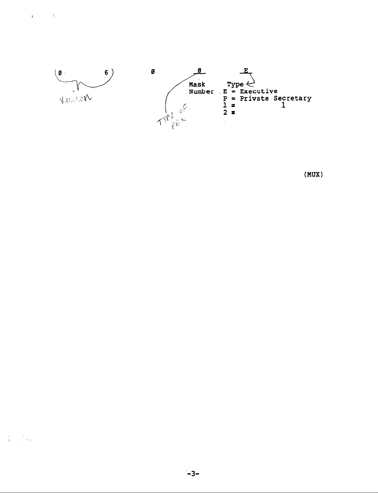
Part of the display will be a number as shown'below:
=
PROGRAMMING
Secretary
=
Secretary 2
1
Before programming, fill out
next several pages or the tables in the regular SET-30 documentation.
Separate sets of tables are provided for Multiplexer
Groups (one or two secretaries
tive/Private Secretary combinations.
For stand-alone executive phones,
tive/Private Secretary table which is applicable.
the database tables shown on the
(MUX)
and many executives) and Execu-
use the portion of the Execu-
'A3-
Page 4
,---
‘\
‘;
---e-w--~
-------a--
El
4
---
:
4
4
---
-4-
Page 5
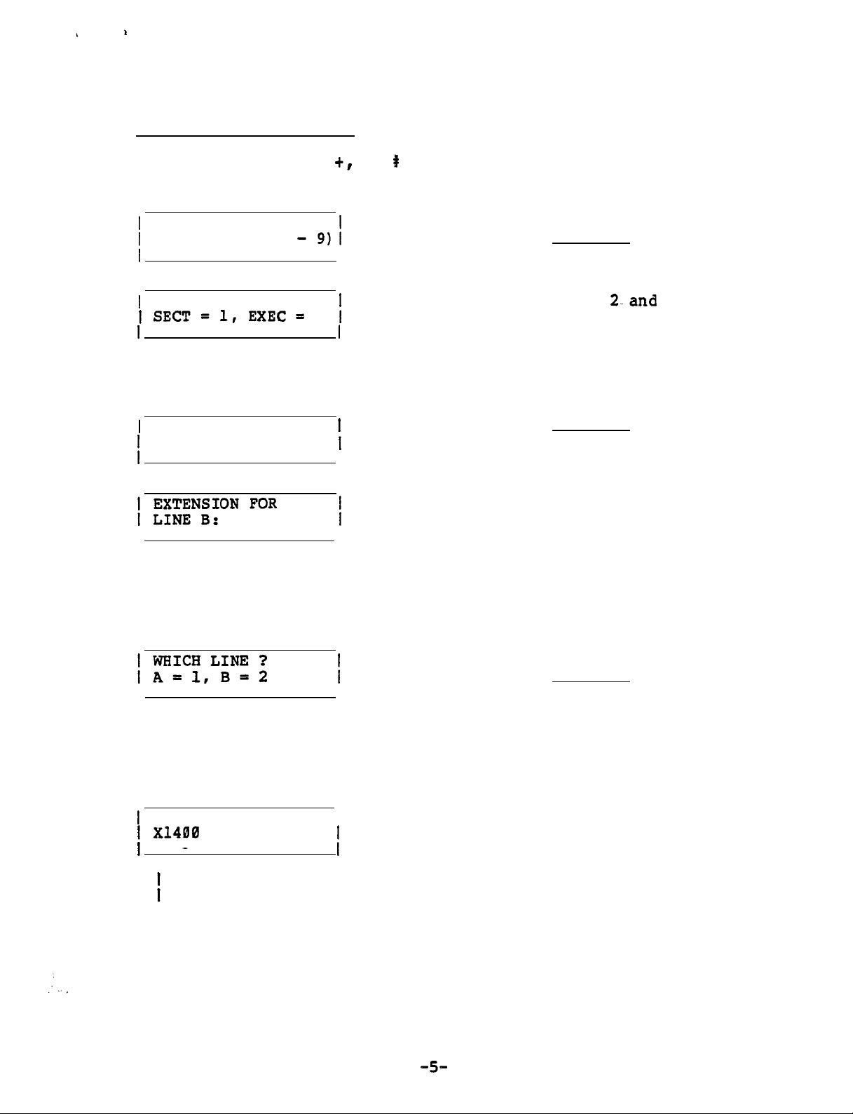
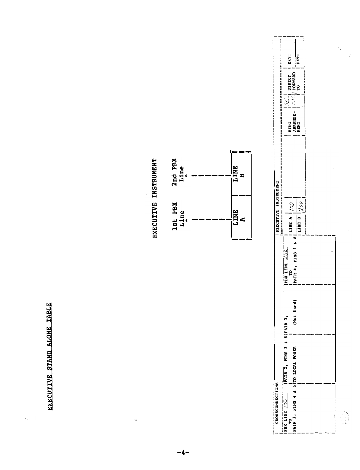
EXECUTIVE (Stand-Alone)
Press STORE, FEATURE
0, # buttons in sequence.
+r
INVALID display between buttons.).
j
SELECT MASK (0
Enter and STORE
I
I
SELECT MODEL
1 SECT=l,EXEC=
I
Press
I
EXTENSION FOR
1
LINE A:
i
STORE and COM (3rd ivory button in bottom row) in sequence
2
;
I
I
Enter 2-and
Enter and STORE
(Normally not used) Enter STORE
(Disregard
STORE
To display the programmed lines
, perform the following procedure:
Press DISPLAY and COM (3rd ivory button in bottom row) in sequence
Enter
and STORE
Not applicable at
EXECUTIVE Station Line requested (A or B)
I
I
I
V V
1 COM = NO
1 x14!0
A
LINE Al
I
Extension number of requested line (XNONE if none is assigned)
-5-
Page 6
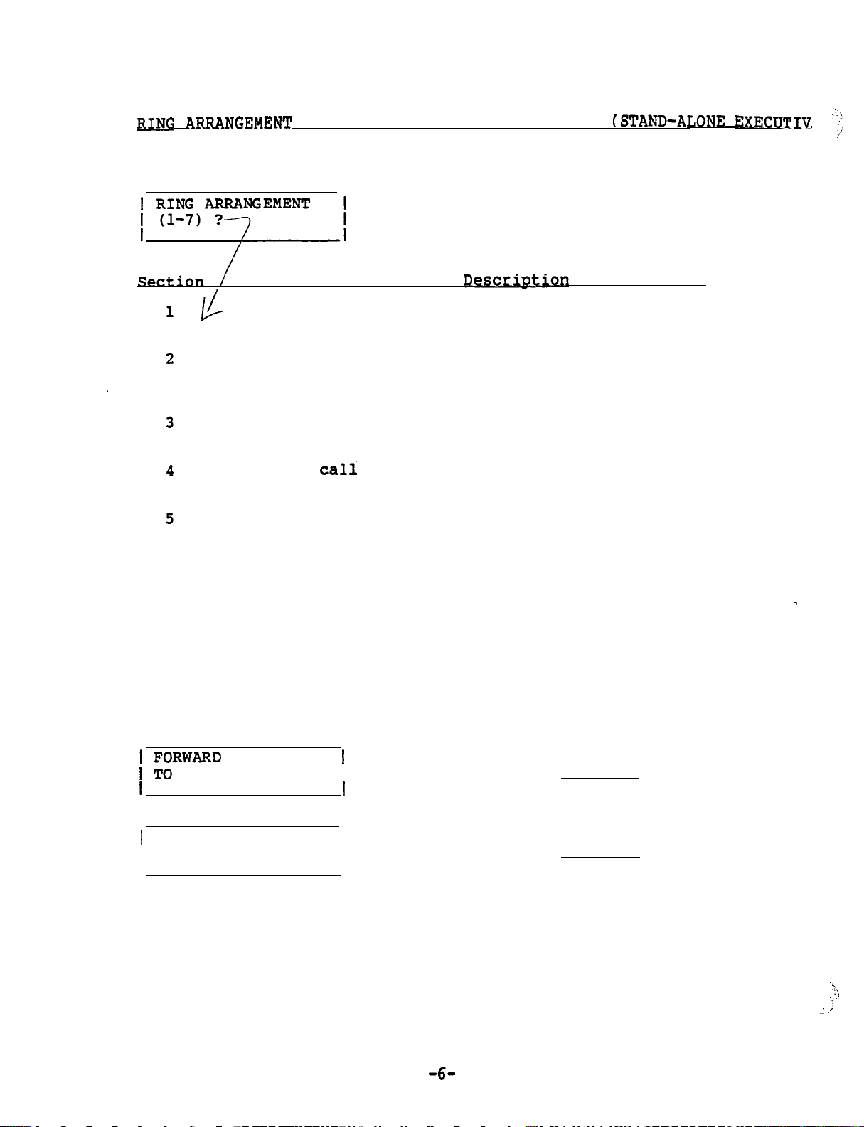
MNC
ARRANGEMENT AND DIRECT FORWARD DESTINATIONS
Press STORE
and
DIRECT FORWARD buttons in sequence
Ring arrangement need not be entered.
Press STORE
If no ring arrangement is programmed,
automatically defaults to arrangement 1.
(STAND-ATlONE EXECDTIV
it
'.!'j
/'
1,
Descr..&ption
/
Duplicate ringing. Rings both secretary's and
. .
executive's phones.
Delayed duplicate ringing.
phone.
After two rings, the call also rings at
Rings of executive's
the secretary's phone.
Executive answers. Rings only at executive's
phone.
Full
cali
screening. Rings only
at
secretary's
phone.
Overflow call screening.
executive's phone.
Subsequent calls will ring
Rings first call at
at the secretary's phone as long as the executive's
phone is busy.
Primary line call screening.
Line A designated as
_
primary line, and rings at the secretary's phone.
Line B designated as secondary line, and rings at
executive's phone when idle. If line B is busy,
calls ring at secretary's phone.
7
) ;yARD
LINE A
Secondary line call screening.
are reversed.
I I
1
FORWARD LINE B
I TO
Same as 6 but A and B
1
I
I
-6-
Enter and STORE
Enter and--STORE
; .,
.\
:.:
j
Page 7

To display Ring Arrangement and Direct Forward Destination perform the
following procedures:
Press DISPLAY and DIRECT FORWARD buttons in sequence
station to which chosen
line is forwarded
I
V
I AFWD to 1400
1
1 DUPLICATE RING
A
I
Ring Arrangement used
/
-Enter
and STORE
-7-
Page 8
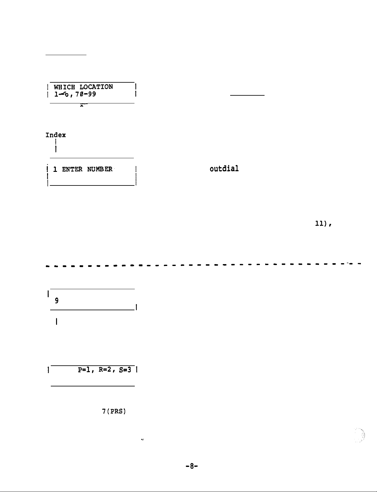
SPEED DIAL
Press STORE
) y;CH,;OFION
I
-' &-
Speed Dial Indexes
1n;fex
being programmed
I
and
SPEED DIAL buttons in sequence
I
I
I
t l ENTER
I
56 digits maximum
(only last 12 will
be displayed in
bottom row as entered
------------
Press SPEED DIAL button
NuMBER’
I
I
_____----------------------
Enter but do not press
STORE unless you want to skip
the next step (just change name,
not telephone number).
If the instrument is to merely
outdial
phone number and STORE (preceded
by the PBX trunk group access code
for the trunk group to be used,
unless the instrument is connected
directly to CO trunks).
If additional commands are
required (see Table page
perform the procedure in the
dotted lines between the digits
where an additional command is
required. Several commands may
be programmed in succession.
digits, enter the tele-
ll),
1
1 ENTER (ALPHA)
I
I
g
A
I
Number programmed so far
Note: Each numbered Key except
has two letters and a dash).
.
1
USE:
I
Display shows the result of
pressing the
the previous step
Continue the procedure until the command sequence is finished.
three,
P=l, R=2, S=3 1
another entry is necessary.
7(PRS)
I
0 and 1 has three letters (0 Key
I
key in
"
Press tone pad Key which
corresponds to the alpha
character desired.
In order to select one of the
Press Key pad number which
corresponds to the desired
letter shown on left, but do
not press STORE button.
-a-
Page 9
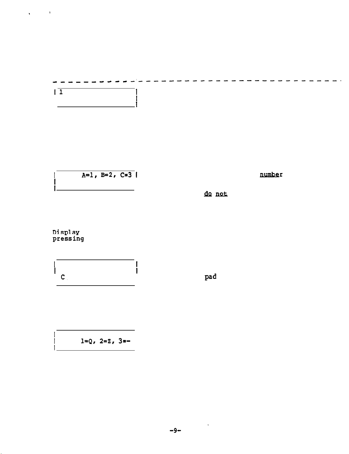
Press the SPEED DIAL button each time a change from numbers to
alpha characters or vice versa is required.
When the entire string of numbers and alpha characters is
finished, press the STORE button..
------e--e
_I__------------------_______
1 1
ENTER NAME
I
‘Press tone pad Key which
corresponds to the first
I
I
letter or number of name
(Key 1 is used for space).
If no name is desired,
press STORE.
Note: Each numbered Key except 0 and 1 has three letters (0 Key
has two letters and a dash).
In order to select one of
the three, another entry is necessary.
1
USE:
A=l, B=2, C=3 1
Press Key pad
number
which
corresponds to the desired
I
letter shown on left, but
&J
&
press STORE button
unless name is finished.
If a number was selected in
the previous step, press
Key 4.
Disulav
preising
shows the result of
the 2 (ABC) key in
the previous step.
I
1
ANSWER PHRASE?
I
c.
I
Enter next letter on tone
pad
Display shows the result of pressing the
3 key in the previous step to select the
third letter of the three choices.
/
USE:
l-Q, 2-Z, 3=-
I
Select desired character
I
Display shows the result of pressing the
8 (QZ-) key in the previous step
Continue the procedure until the name is finished (12 characters
including spaces maximum),
then press the STORE button.
-g-
-
Page 10
I
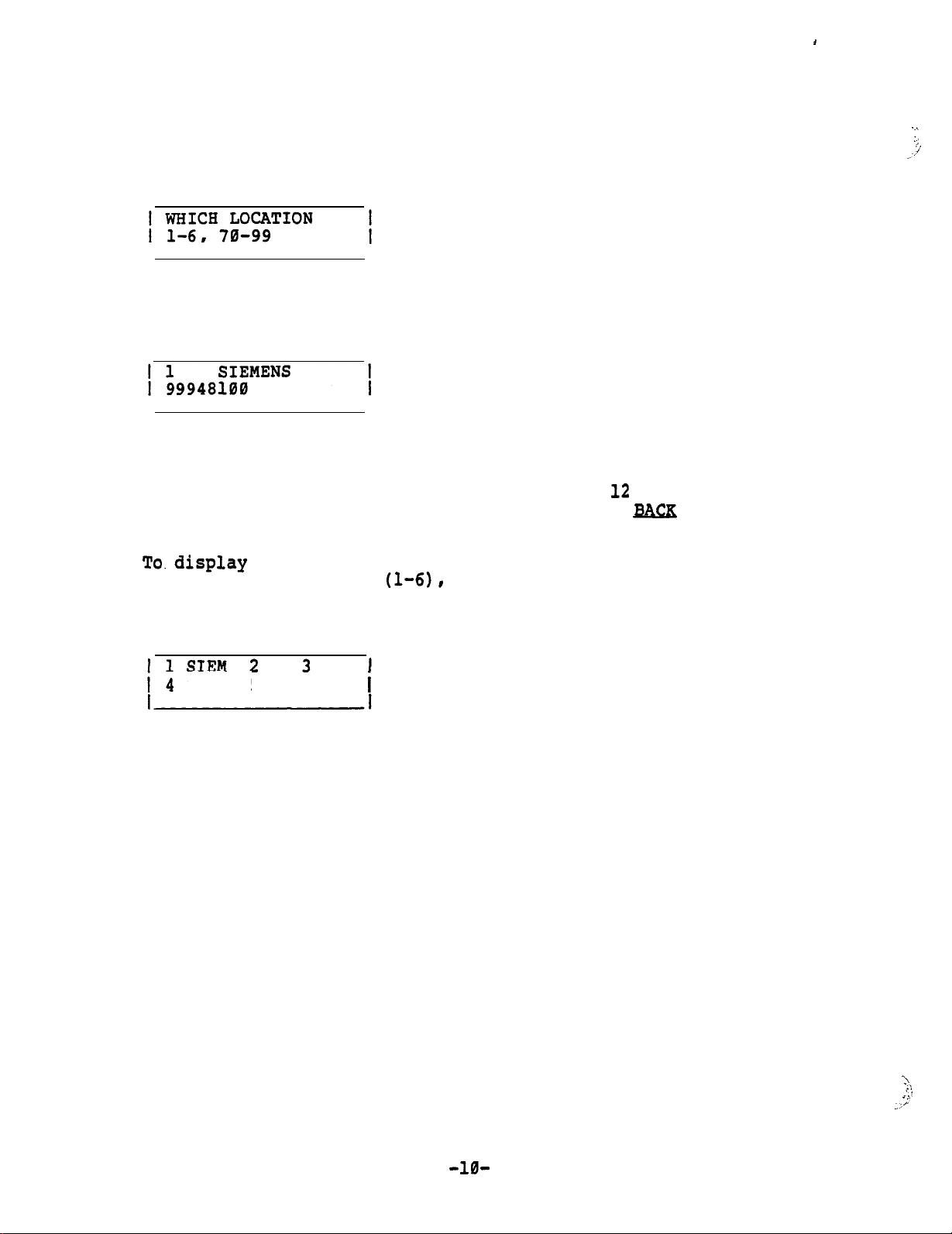
To display SPEED DIAL numbers perform the following procedure:
.~
::;
,i
Press DISPLAY and SPEED DIAL buttons in sequence
Enter index'to be displayed
Index Name
I I
V V
Number dialed
Note:
The display will show only the last
more than 12 digits are used, press the
(trunk group access code and address)
12
digits. If
B&X
button
to view the remaining numbers.
To.display
six speed call indexes
the first four letters of the names for the first
(l-61,
perform the following procedure:
Press SPEED DIAL button
5 6
-10-
\
-4
::
: :.
_;,
Page 11
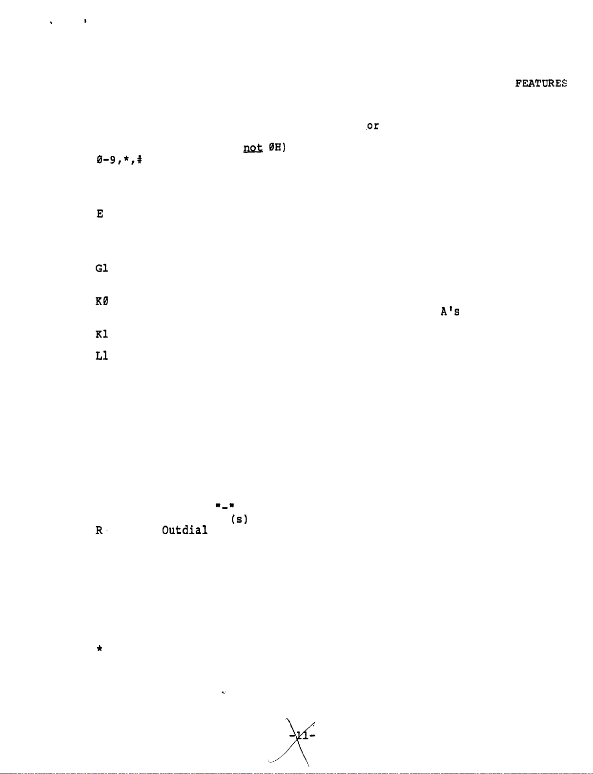
This Table Is Used For Programming SPEED DIAL And Access to P
BX
FEATURES
SUMMARY OF FEATURE SEQUENCE CODES
The following codes as used in feature +
OH
0-9,*,#
A
B
C
D
E
F
GI
GL
GR
Gl
or 2
H
J
K0
On hook (OH ti
0H)
DTMF tones
Any tone detect
Busy tone detect
Control tone detect
Dial tone detect
Insert the extension number of the active line
Timed Hookflash/Connect
Get an idle line and connect
Get a line --
now active or idle
Get ringing line and connect
Get line 1 or 2
Hang-up
Jam display with blanks
Allows user entry of digits,
digits equal the number of digits in LINE
An underline cursor will be displayed.
Kl
to 9
number.
Allows user entry of 1 to 9 digits.
,or
speed dial sequences
and proceeds after total
A's
extension
A underline cursor
will be displayed.
Ll
to 6
Chain a speed dial location *
L70 to 99
NA
Terminate if no tone.
NB Terminate if no busy tone.
NC Terminate if no control tone.
ND Terminate if no dial tone.
NI
NR
Nu
Terminate if selected line not idle.
Terminate if selected line not ringing.
Terminate if selected line not in use
P Pause
S
Stored name remains until hang-up.
U Display an underline cursor after name.
W Wait for call back ringing.
X Ignore automatic dial tone detection.*
for clarity.*
"-"
(s)
to be forwarded.
GF
R.
Display
Get line
Outdial
forwarding destination(s) as programmed.
*
Normally used in SPEED DIAL storage only, do not use
in feature sequence.
Page 12
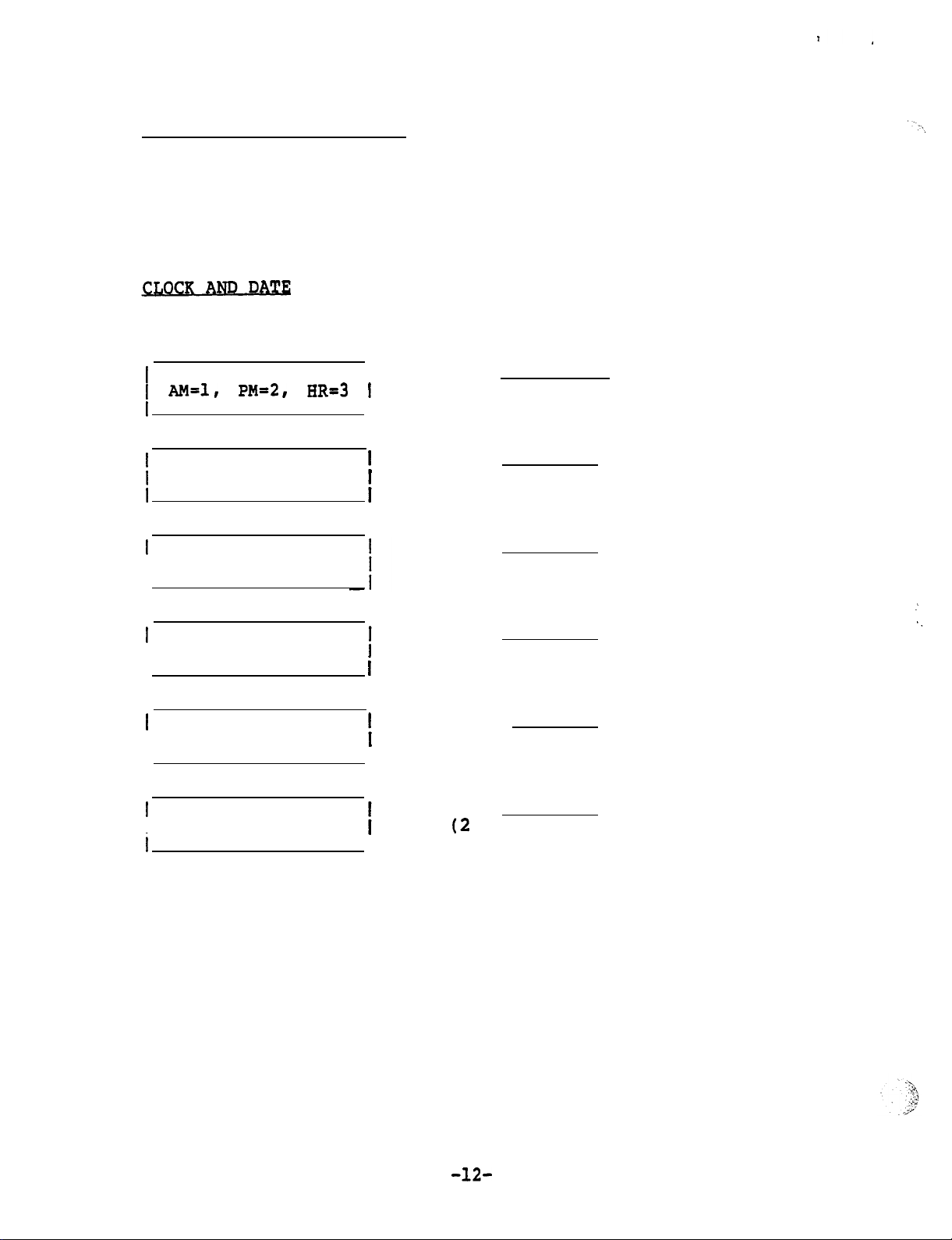
LOUDNESS and TONE of RING
Press Volume
or Volume
To increase loudness, press the VOLUME
button. Instrument will ring.
button.
To decrease loudness, press the VOLUME 'button.
To change the tone
, press tone pad buttons 1 through 9 until
desired tone is received.
Press STORE and DISPLAY buttons in sequence
I
SELECT MODE
I
Enter
and STORE
1 AM=l, PM=2, HR=3 1
I
I
Enter and STORE
/
ENTER HOUR
(24-hour time if 3 was chosen in
last step)
1
ENTER MINUTES
Enter and STORE
I
1
ENTER MONTH
I
i
Enter
(Numeral)
i
and STORE
.’
‘.
1
ENTER DAY
I
1
ENTER YEAR
I
i
Enter and STORE
Enter
(2
digits)
I
and STORE
-12-
Page 13
PROGRAMMABLE
FFATURR
BUTTONS
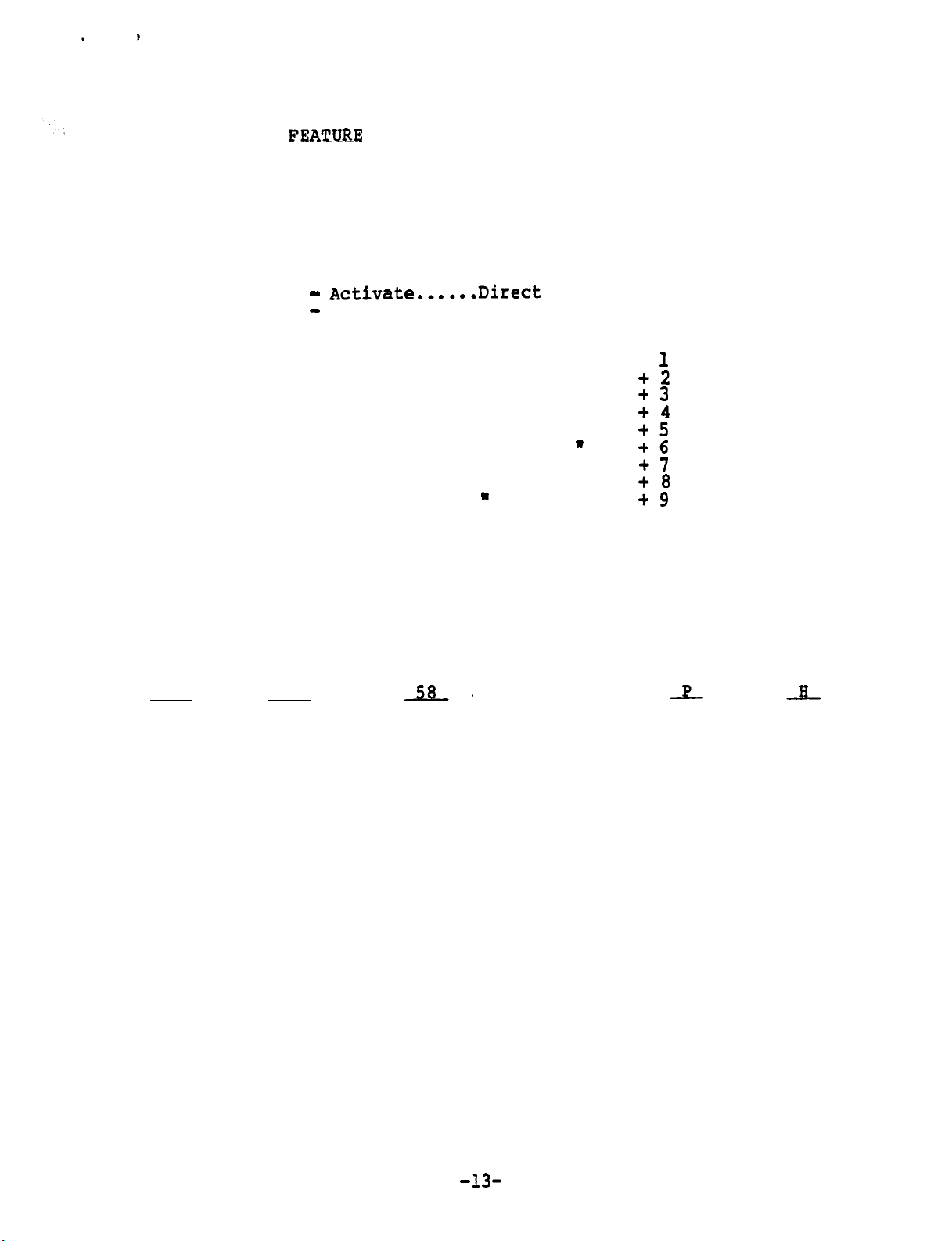
Fourteen PBX features may be programed to be accessed by a single
button or a combination of two buttons.
Conference Call
Call Park
Pick Up
. . . . . . . . . . . . . . . . . . . . . .
. . . . . . . . . . . . . . . . . . . . . . . .
Direct Forward -
. . . . . . . . . . . . . . . .
Activate.,....Direct
Conference Button
Call Park Button.
Pick Up Button
Forward Button
Direct Forward - Deactivate....Direct Forward Button
Any nine
PBX features
Note:
Even the CONF, PARK, and PICKUP buttons listed above may
FEATURE + button +
W
W
W
W
W
W
W
W
W
W
W
W
W
W
W
W
I
+2
+3
+4
+5
+6
+7
+8
+9
be programmed with a different feature, but the label
would have to be changed.
The table two pages ahead is used to program a string of commands
for SET-30
Example of
GL
to perform.
a command string for Call Forwarding.
ND
58.
KO
Get a Terminate PBX
Line if no Access
Dial Tone Code
for the
Allow Pause Hang
user to
-dial digits
equal to
UP
call number in
Forwarding user's station
Feature
number
(Dial it)
In order to save time it is recommended that the table on the
next page be used for this purpose.
It shows the command string
for the most commonly used features.
-13-
Page 14
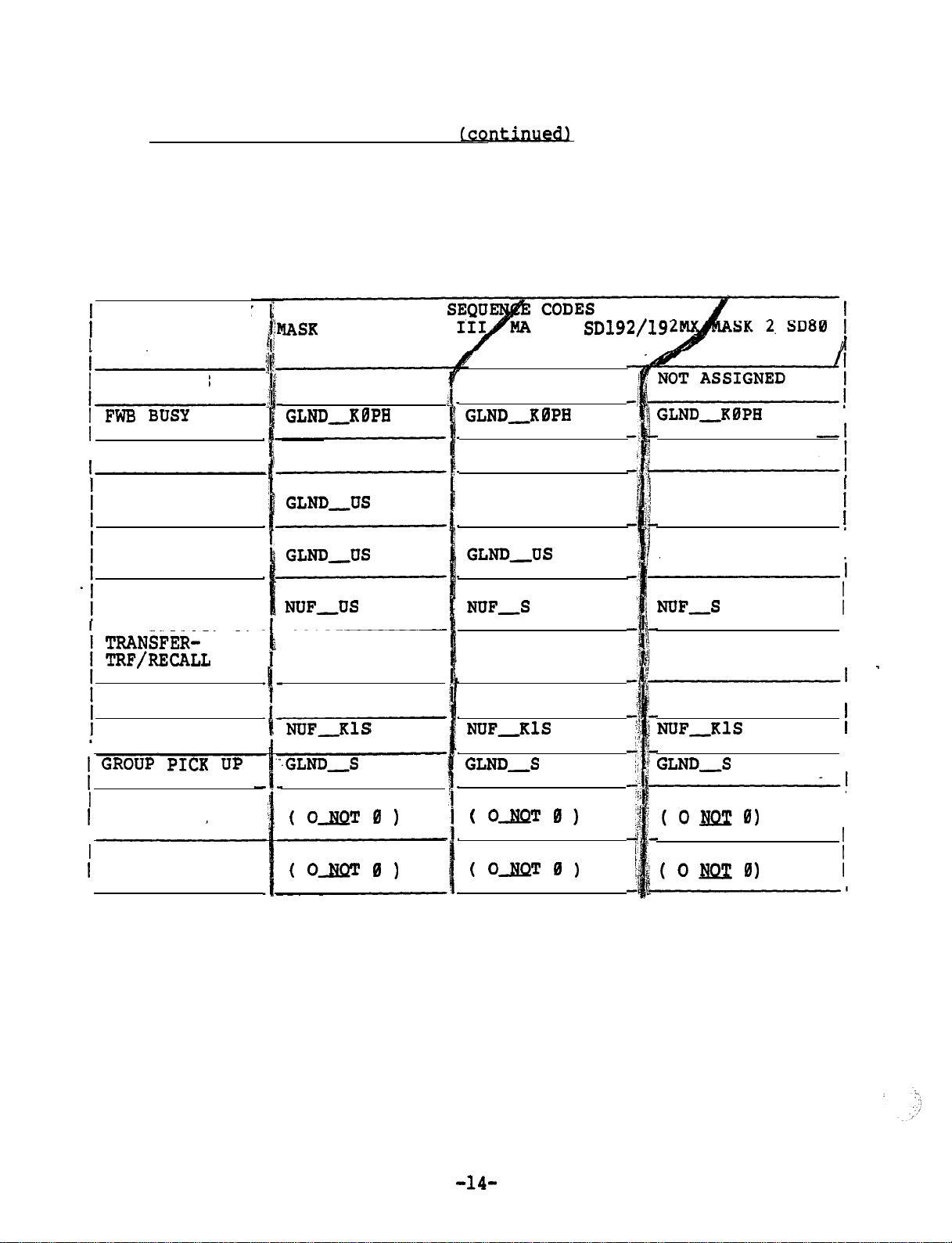
PROGRAMMABLE FEATURE BUTTONS
(cwued)
.
Copy the command string except for the access code.
code of the particular PBX with which the SET-30 is to be used.
The existing command string can also be displayed first and then
copied with the new access code.
FEATURE ACCESS SEQUENCE CODES
1
FEATURE OR KEY
1
AND FEATURE
I
NAME
1
FWN NO ANS GLND,KBPH
I FwB
BUSY
I FWC CANCEL
IND SPEED
(THRU SWITCH)
GRP SPEED
(THRU SWITCH)
HLD PBX
(SWITCH HOLD)
llASK
0 SATURN II/
GLND-KBPH
GLND,PH
GLND,US
GLNDJJS
NUFJJS
SK 1
GLND,KBPH
GLND-KBPH
GLND,PH
NOT ASSIGNED
GLND-US
NUF,S
SD192/19
Use the access
GLND-KBPH
GLND,PH
NOT ASSIGNED
NOT ASSIGNED
NUF,S
I
I
I
TRANSFERTRF/RECALL
CONFERENCE
CALL PARK
I GRoUP
I
DIRECT FORWARD
I
(ACTIVATE)
1
DIRECT FORWARD
I
(DEACTIVATE)
I
In order for the end user not to accidentally reprogram the command
string, a security Key (code) has to be entered to program the features.
The SET-30 remains in the feature programming mode until timeout or
until the HANG UP button is pressed.
p1cK
up
NUFUS
NUFKBS
.GLND-S
GFNUNDRPOH
( OJIQT 0 1
GFNUND,POH
( O-ND 0 1
NUFUS
NUFKBS
NUF-KlS
GLND,S
GFNUNDRPOH
( OJiQT 0 1
GFNUND,POH
( kB!X' 0 1
The security key is:
NUFUS
NUFKBS
NUF-KlSNUF-~1s
GLND-S
GFNUNDRPOH
(ONzr0)
GFNUND,POH
(Ox?z0)
STORE
FEATURE +
0
STATUS
I
I
_
I
I
I
!
I
'Disregard INVALID display between buttons.
-14-
Page 15
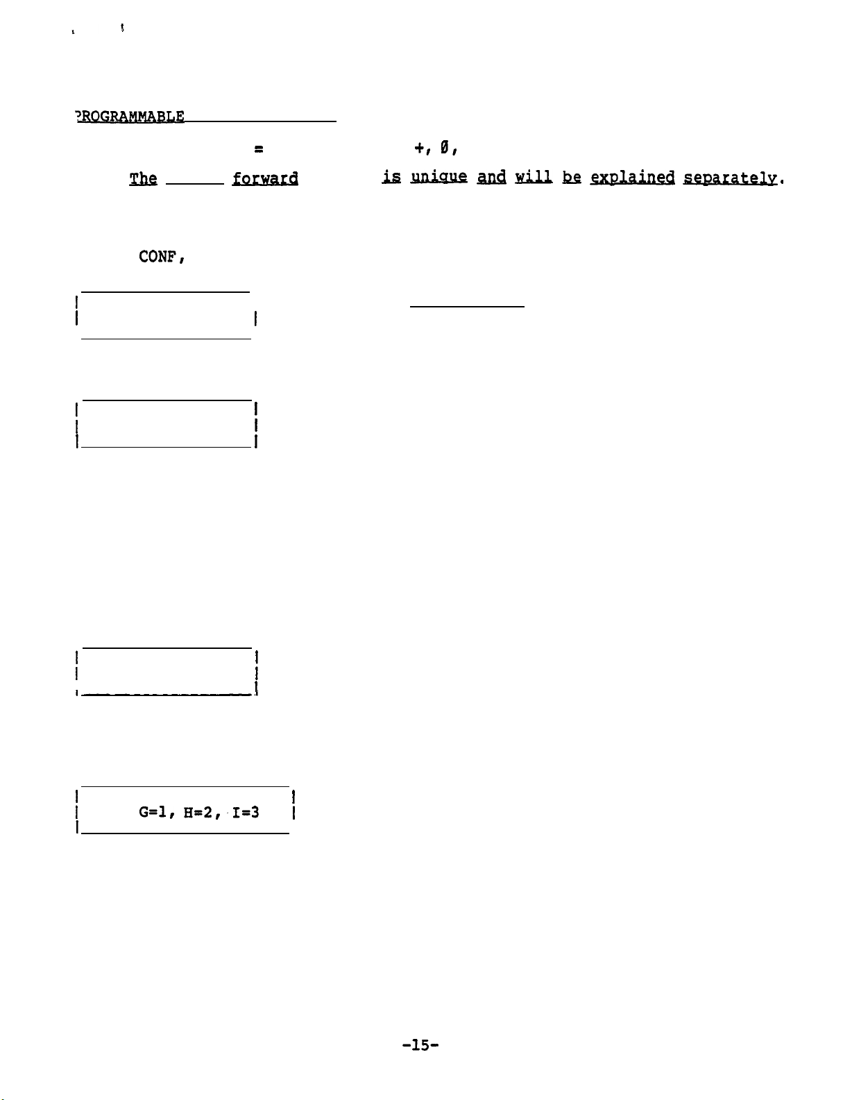
TROGRAM~
Enter security key = STORE, FEATURE +r 0, STATUS
FEATURE BUTTON
S (continued)
Note: j&z direct forward feature
Press STORE and FEATURE button.
If the
If the
1
SELECT PBX
1
FEATURE (l-9)
Feature number (if used)
1
1 ENTER NUMBER
1
FEATURE
CONF,
+ button was pressed,
PARK, or PICKUP was pressed, skip the next step.
I
I
is JuL&W ii&i will ke a@ained
a feature number is also selected.
Enter (Do not press STORE)
Request a string of commands
(See table on preceding page).
If the string of commands starts
with numbers,
If the string of commands starts
with alpha characters, press the
SPEED DIAL button and the next
display shown will appear.
Press the SPEED DIAL button each
time the command string changes
from numbers to alpha characters
or visa versa.
mtelv.
enter the numbers.
Press tone pad key which corresponds to
1
1 ENTER (ALPHA)
I
Note: Each number key except 0 and 1 has three letters (0 key has two
letters and a dash).
entry is necessary.
)
USE:
I
Display above shows the
result of pressing the 4
(GHI) key in the previous step.
G=l, H-2,.1=3
1
I
I
the alpha character desired.
In order to select one of the three, another
Press key pad number which corresponds
to the desired letter shown on left, but
do not press STORE button.
-15-
Page 16
~ROGRAMMASLE
i
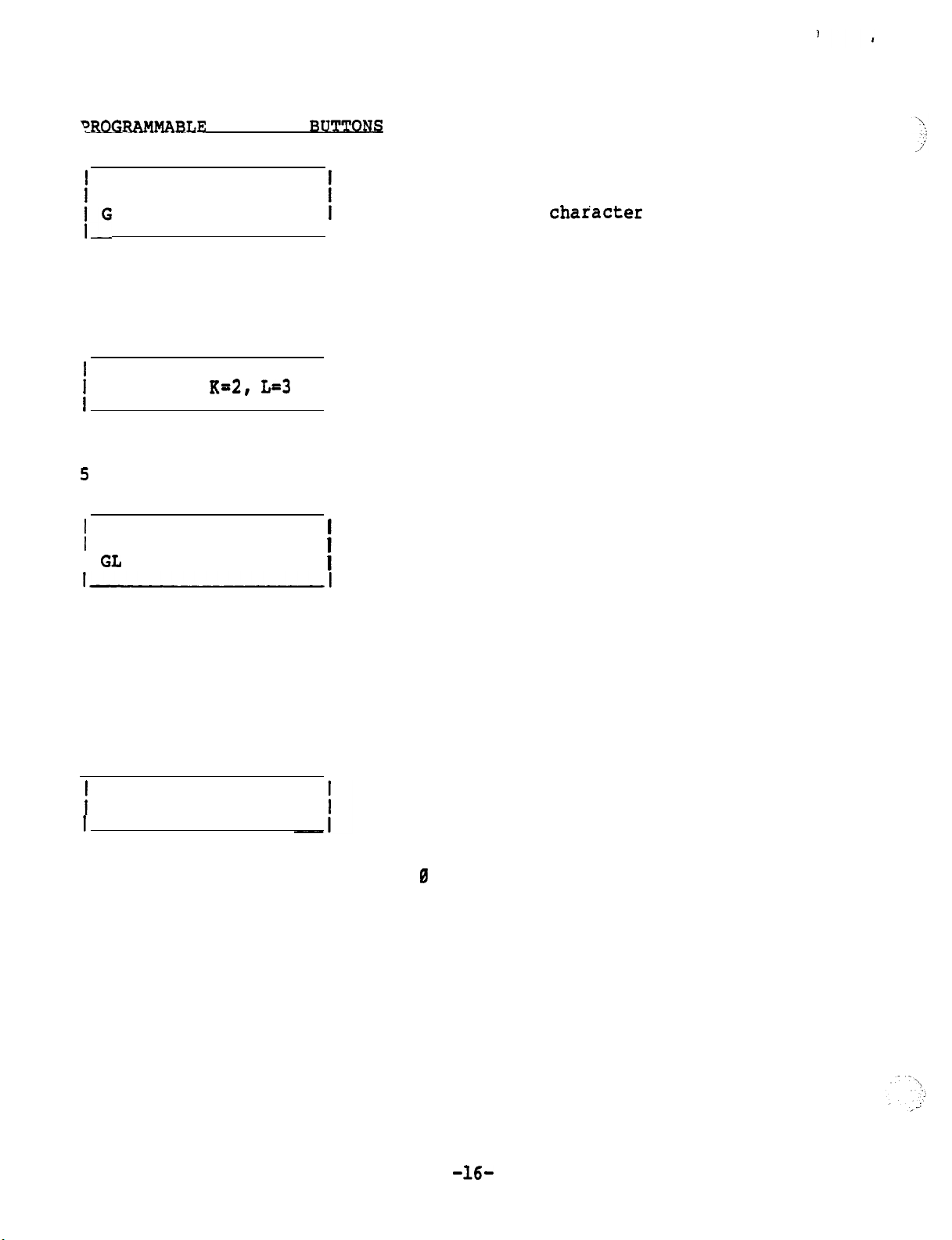
1 ENTER (ALPHA)
I"
Display above shows the
result of pressing the 1
key in the previous step.
j
USE: J-l,
Display above shows the
result of pressing the
5
(JKL) key in the previous step.
1
1 ENTER (ALPHA)
I GL
FEATURE
K=2, L=3
RUTTO~
I
I
I
(continued)
Press key pad number which corresponds
to the next alpha character desired.
(If the next
the SPEED DIAL button first, then enter
the number.
Press key pad number which corresponds to
the desired letter shown on left, but do
not press STORE button.
char'acter
is a number, press
Display above shows the
result of pressing the 3
key in the previous step.
Note: The command up to this point is "Get a Line, now active of idle".
Continue the procedure until the command sequence is finished, then press
the STORE button.
Press tone pad key which corresponds to
1
ENTER NAME
I
Note:
Each numbered key except 0 and 1 has three letters (0 key has
two letters and a dash).
another entry is necessary.
If the number 1 was selected to be used a number or a space,'the
display will be different.
the first letter of number of the name
(key 1 is pressed twice for space)
In order to select one of the three,
-16-
Page 17
PROGRAMMABLE FEATURE BUTTONS (continued)
I
/
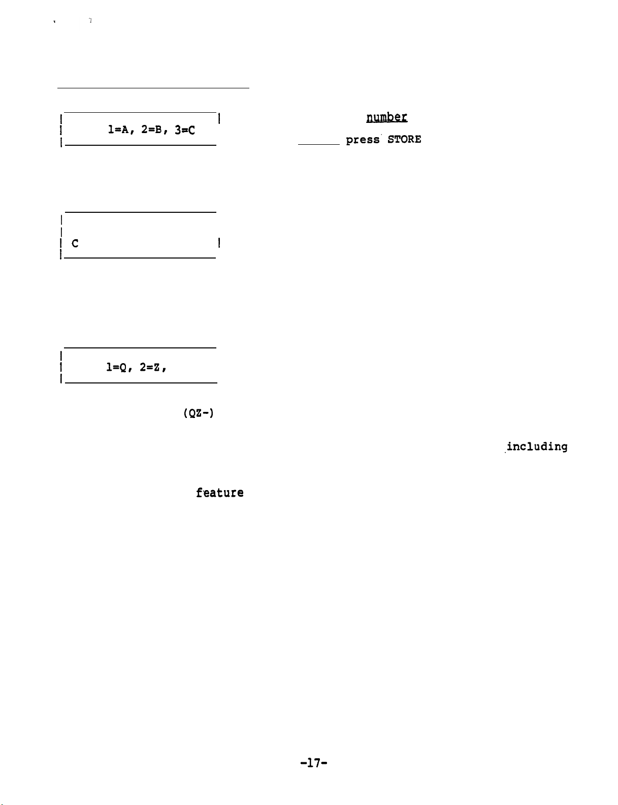
USE:
Display shows the result
of pressing the 2 (ABC)
key in the previous step
1
ENTER NAME
I c
I
Display shows the result
of pressing the 3 key in
the previous step to
select the third letter
of the three choices.
/
USE:
Display shows the result
of pressing the 8
key in the previous step
l=A, 2=B, 3=C
l=Q, 2=Z,
3=-
(QZ-)
I
I
I
I
1
I
Press key pad number which corresponds
to the desired letter shown on left,
but do not
name is finished.
If a number was selected in the previous
step, press key 4.
Enter next letter on tone pad
Select desired character
press'STORE
button unless
Continue the procedure until the same is finished (12 characters
spaces and dashes maximum),
For the DIRECT FORWARD feature,
one to activate the
the same button is used.
After entering the feature programming security key (code), perform the
following steps:
f-eature
then press the STORE button.
two command strings have to be programmed,
and one to deactivate the feature,.although
,including
-17-
Page 18
PROGRA~LE
Direct Forward Activate
FEATURE RUTTONS
.
(continued1
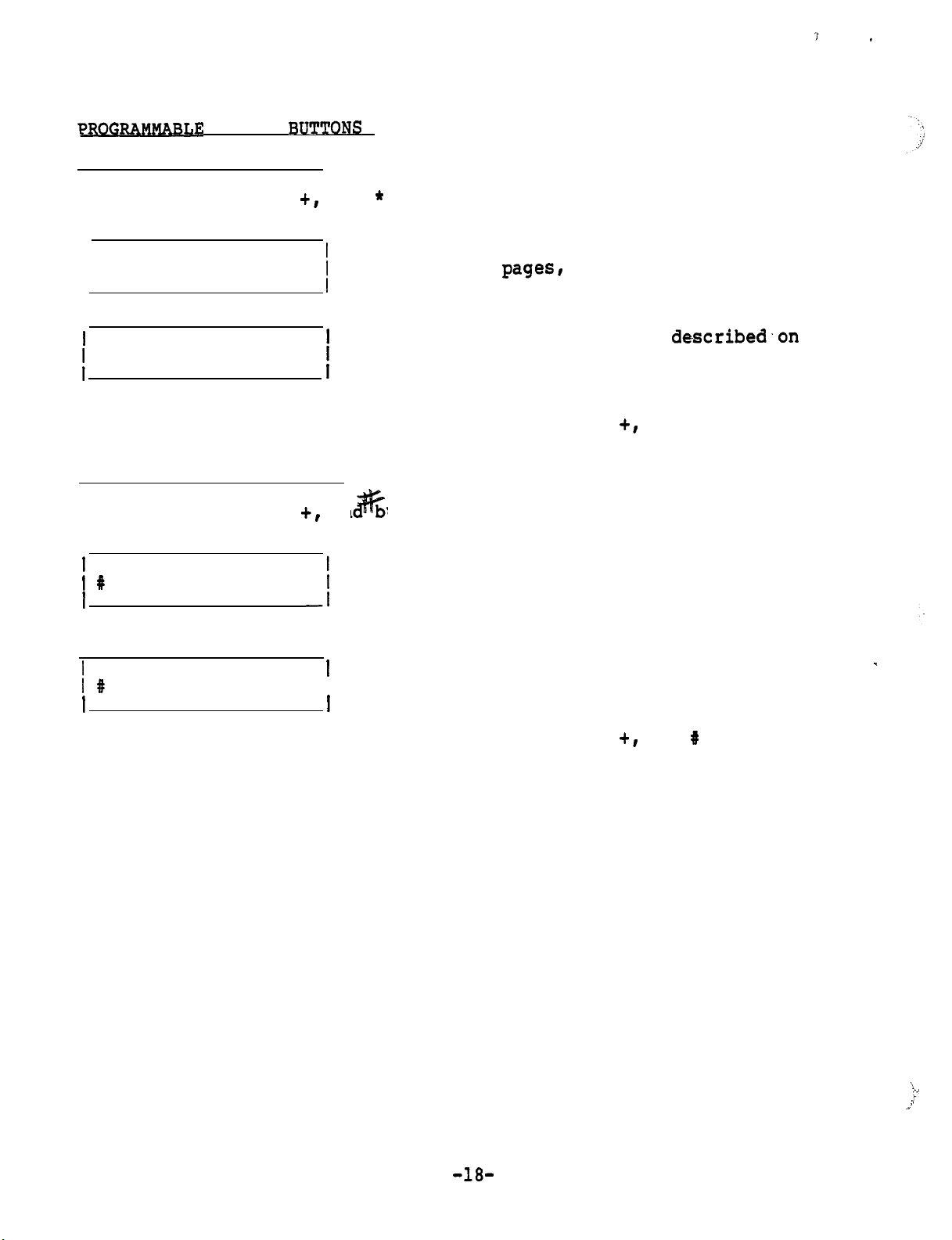
Press STORE, FEATURE
and * buttons in sequence.
+,
Using the same procedure described on
* ENTER NUMBER
I
I
/
previous
and press STORE.
Using the same procedure
* ENTER NAME
/
previous pages,
and press STORE.
To display the feature, press the DISPLAY, FEATURE
pagesl
enter the command string
described.on
enter the feature name
+,
and * buttons in
sequence.
Direct Forward Deactivate
Press STORE, FEATURE
1
t #
ENTER NUMBER
.
an uttons in sequence.
+,
Using the same procedure described above,
enter the command string and press STORE.
I
I
1 #
ENTER NAME
I
I
I
To display the feature, press the DISPLAY, FEATURE
Using the same procedure described above,
enter the feature name and press STORE. .
+,
and 8 buttons in
sequence.
-
\
:-’
.I
a’
-18-
Page 19
PROGRAMMABLE FEATURE
BUTTO%
(continued)
No
te:
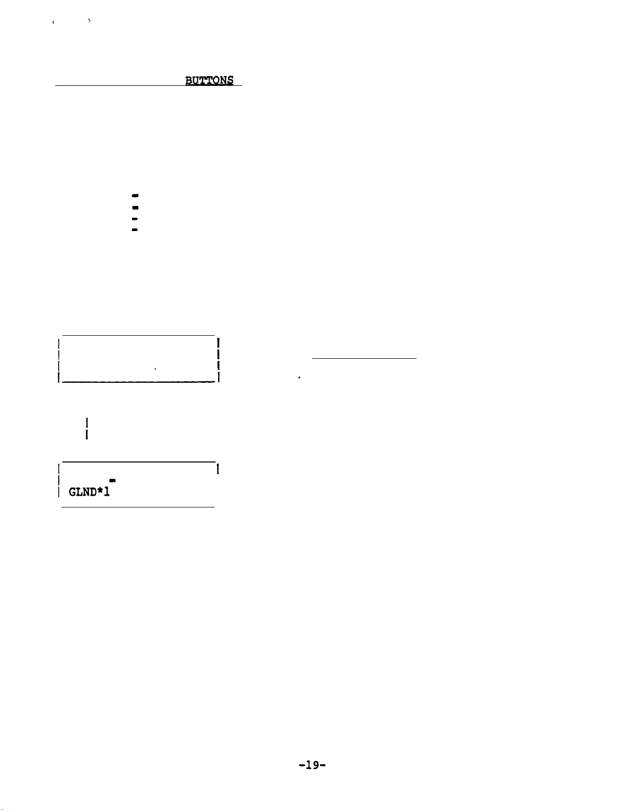
When the FEATURE + button is pressed,
the first three letters of
the feature name are displayed for features 1 through 6. In order
for the user to recognize the feature, the first three letters
should clearly show the entire feature. 'When using the feature,
the entire name is displayed.
Examples of Feature names:
FWN
- NO ANSWER
FWB - BUSY
Fwc
CANCEL
-
UN1- ZONE ONE
To display the feature
Press
DISPLAY
and feature button
If the FEATURE + button was pressed,
, perform the following procedure:
a feature number is also selected.
If one of the other buttons was pressed, skip the next step.
1
SELECT PBX
I
FEATURE (l-9)
Enter
Feature Feature
Number Name
f
I
V V
I
1
4 UNA - ZONE ONE
I GLND*l
I
COMMAND STRING
I
I
-19-
Page 20

I
SET-30 PROGRAMMING
./:
This exercise contains four different SET-30 configurations.
Complete the database tables in the back of this booklet for each of
the configurations.
The database tables also contain some wiring information for easy
identification of each station.
After completion of the database tables
, program each of the configur-
ations.
RINGING ARRANGEMENT
Selection
1
Duplicate ringing.
Description
Rings both secretary's and executive's
phones.
2
Delayed duplicate ringing.
After two rings,
the call also rings at the secretary's
Rings at executive's phone.
phone.
Executive answers.
Full call screening.
Overflow call screening.
Rings only at executive's phone.
Rings only at secretary's phone.
Rings first call at executive's
phone. Subsequent calls will ring at the secretary's phone
as long as the executive's phone is busy.
6
Primary line call screening.
Line A designate as primary
line, and rings at the secretary's phone. Line B designated
as secondary line,
If line B is busy,
7
Secondary line call screening. Same as 6, but A and B are
and rings at executive's phone when idle.
calls ring at secretary's phone.
reversed.
-20-
Page 21

EXECUTIVE
f=-RY
COMBINATION(THE-
Exercise
The following Executive/Private Secretary combination will be used.
Extension 1300 will appear on Line A of both instruments.
Answer Phrase is Siemens.
Extension will ring at Secretary.
Direct Forward Destination is Ext. 200.
Extension 1301 will appear on Line B of both instruments.
Answer Phrase is JANE DOE.
Extension will ring at Secretary.
’
Direct Forward Destination is Ext. 211.
The executive’s ring arrangement is full screening of
SECRETARY INSTRUMENT
1ST
PBX LINE
I
~~------_
CROSSCONNECTIONS
I---
I
PBX LINE
IPAIFI,
IOF
lOF
I
l
IF CONNECTED
ON BOTH INSTRUMENTS.
PAIRS 1 6 4
BUTTON OF EACH OF THE
LINE
;j!jj-
PINS 4 6
SECRETARY SET
EXECUTIVE SET* iLOCAL POWER AND
----
MAY BE
BUTTON OF
IPAIR
2, PINS 3 a
lOF
EACH
5lTO
LOCAL
l
ICROSSCONNECTINC
IPAIRS
2 ON BOTH
lINSTRURENTS
IS"FFIC*ENT~
AS
SHOWN, THE
REVERSED To HAVE DIFFERENT LINES ON THE FIRST LINE
TWO
EACH
INSTRUMENTS AND (IF USED) AGAIN ON THE SECOND
OF THE
---
INSTRURENTlOF
POWER
i
IS
SAME LINES
'IWO
INSTRUMENTS.
EXECUTIVE
ZND
PBX LINE
I
LiPAIR
3, PINS 2 A
SECRETARY SET
l
To ,PAI:'4, PINS 1 LB:
tPAlR
3.
PTNS
2 ‘
I
4/+,m:2 .-
-\c,.
I
I------
WILL APPEAR ON THE SAME LINE BUTTONS
#l
INSTRWENT
7lPBX
LINE
l
7lnF !3Waf?l’ARy SET
.__._., ., -INS 1 L
tOP EXECUTTVE
. - -
I
u-
so To
-..--- - - _ -
Calls.
PROGRARUING
I.--
l
SECRETARY INSTRUMENT
*******************************************************************************
SET*
l
--.
---
rJ4.q
-~~K%~KK%RIJ~~~%~-~.********.**********************************************************************
i
;
LINE B
I I I
_
.
I
~z%
I
;9;‘%\~;
I_
-_---_______- __--
I RING HERE
l
__----
___----__---
l
I
FORWARD
I
L”-.-
I
l
DIRECT
17
I
--
-------
t--AL1
1 EXT=%Y
i
I EXT:
I-----
EXT~
------.
HA
NA
1
i
t
I
Page 22

EXECUTIVERY
W4.iUNATION
IONE PBX LINE ON BOTH INSTW4E.DTS. ANOTHERCUTIVE
INSTRUMENT ONLY)
The following Executive/Private Secretary combination will be used.
Extension 1300 will appear on Line A of both instruments.
Answer Phrase is Siemens.
Extension will ring at Secretary.
,’
Direct Forward Destination is Ext. 200.
Extension 1301 will appear on Line B of the executive’s instrument only.
(Direct Forward Destination is Ext.
The executive’s ring arrangement is duplicate ringing.
SECRETARY INSTRUHENT
I '
l$T PBX LINE 2ND PBX LINE
-I __________
I LINE 1
I A
I~----I~----I~-_.---I
:
PBX LINE ,
i
PAIR 1,
3F
I’
PAIR I, PINS 4 L
DF EXECUTIVE SET* ILOCAL POWER AND
L;NE ; I"C;;R- 1
___------
CROSSCONNECTIONS
------___-
To
PINS 4 L
SECRETARY SET
AND ALSO TO
I1
IPAIR
IOF
5lTO
i
INOTE:
51ONE
ICROSSCONNECTING
(PAIRS
I INSTRUMENTS IS
2, PINS 3 L
EACH
INSTRUHENTlOF
LOCAL
POWER
CONNECTING
INSTRUMENT
2 0~
'ID l
BOTH
Exercise
EXECUTIVE
I I I
___--
___-___-
6lPAIR
3, PINS 2 L 7lPBX LINE __
SECRETARY SET
IPAIR 3Top~~s
IOF EXE&ITIVE
INSTRURENT
I
2
& iloF fE;Rp;YgET
SET
'I
#2
211.
I
-_~-
I
IPA&,
I
IPAIR
lOF
PINS 1 L
4, PINS 1 L
EXECUTIVE SET*
l
PROGRARUINC
I
I SECRETARY INSTRUMENT
laPPIIEPtPPPtlPIPSPIPCEDD=PDIPEPSESEPSP=aaaaaa.aaaaaaaaaaaaaaaaaaaaaaaaaaaaaaaa=
Bl
I EXT 1
8hxT
2
--IT--I
___--_--_---____-_--____
--
1
I
I
I I
------- ----
__--_____
I
I
3= DELAY I NA '
____ ---- ____ --
----_-----
I---------
I
DIRECT I EXT:
FORWARD I-=--
1
TO
------
rNA
-
IF CONNECTED
ON BOTH INSTRUMENTS.
PAIRS 1 L 4 MAY BE REVERSED Tk'HAVE DIFFERENT LINES ON THE FIRST LINE
BUTTON OF EACH OF THE
LINE BUTTON OF EACH OF THE lW0 INSTRURENTS.
AS SHOWN,
THE SAME LINES WILL APPEAR ON THE SAME LINE BUTTONS
'IWO
INSTRUHENTS AND (IF USED) AGAIN ON THE SECOND
Page 23

ON ROTH
1-s
SECOND PBX
m
TO
SEC-
ONJ,Y.
THIRD PBX LINE TO EXECUTIVE
Ou
Exercise
13
The following Executive/Private Secretary combination will be used.
Extension 1300 will appear on Line A of both instruments.
Answer Phrase is Siemens.
Extension Will ring at Secretary.
Direct Forward Destination is Ext. 200.
Extension 1301 will appear on Line B of the Secretary’s instrument only.
Direct Forward Destination is Ext.
211.
Extension 1302 will appear on Line B of the executive’s instrument only.
Direct Forward Destination is Ext
1220.
I
E
The executive’s ring arrangement is delayed duplicate ringing.
I
SECRETARY INSTRUMENT
1ST PBX LINE
I
I----- l~__II_IITI___=IIISITT
!
I----- I-----
ITINE
I"- I2-- I"""---
------ ----- - ----- !
lPBX
i
IPAI?l,
lOP
SECRETARY SET
IPAIR 1
lOF
EXECUTIVE SET
i
.
.-_
I LINE I
CROSSCONNECTIONS
LINE
PINS 4
AND ALSO To
PINS 4
INTER-I
---- -__-~_________--------~--
6
6
---------------I___----_----
I-
I
IPAIR 2. PINS 3 b 6lPAIR 3. PINS
lOF EACH INSTRUHENTiOF hECkETA&
SIT0 LOCAL POWER
INOTE: CONNECTING
510NE INSTRUMENT To
ILOCAL POWER AND
ICROSSCONNECTING
IPAIRS
IINSTRUMENTS IS
ISUFFICIENT.
2
ZND PBX LINE
ON
BOTH
I
-______ ---------___
~-__---------
2 C 71PBX LINE __
l-0
I,'EXk"Kz
;
I
I
I
SET
2 6 710F EXECUTIVE SET
SET
---I..---.-
EXECUTIVE INSTRUblENT
~RD PBX
LINE
1
___
-L--l.
1
LFE 1 L;NE i I;;;"- 1
I-I-_-- I-----
l
1PAI;T04
I
, PINS 1 6Bi==
L----
-- ---- I--
--
I
---.-v---l EXEC"TIh
l
I
L-----
I SECRETARY INSTRUMENT
i-.,X,
I EXT 2
--
;F!NE A
l
LINE B
I--.-.--
~=====--P-==E=--P==-=____5-==__________~~======~~===============
I
I
-..---- I
--------------------
PROGRAMMING
-------- ---- --_
SISSC=D===P===.P=l~lS=PISEED=S===~~~~~~--
1
I I I
1
__
I
INSTRUMENT
-I_--..
ANSWER I-
I PHRASE
l
-_---__-_
~
I-?-
I-+-----
I
I-.--
l
I I
---___-__
_-___
I
I
-----
----
----------
--
_--- --_- __.- --I---------
--__--__-_--__
-----------_-- ---. __-- --_
--SP=SEPE==PE=-II===============ES==____-fIN;,,"ERE 1
I
=
I I
__
_-___
----I
~_______
I
1
RING
I I
l
DIRECT 1 EXT:
l
FORWARD
In,
I--I---
ECZSEEI--
.____i
--====a=
1-m-v;
i
EXT:
_________
NA t
I
i
i
I
i
Page 24

PRIVATE
SE-
Press STORE, FEATURE +, 0, t buttons in sequence. (Disregard INVALID
display between buttons.)
,
/
SELECT MASK (
j
SELECT MODEL
1
SECT-l, EXEC-2
i
;
SECRETARY 1, 2 OR
1
PRIVATE=3
-
Press STORE and
)
WIRED FOR INTERCOM?
1 YES=l,
NO=2
0-9)
COM.
(3rd ivory button in bottom row) in sequence
i
Enter and STORE
I
i
Enter
1
and STORE
I
i
I
Enter
3
and STORE
I
Enter
and STORE
I
1
EXTENSION FOR
1
LINE Xl:
i I
I
i
)
EXTENSION FOR
I
LINE A:
1
EXTENSION FOR
1
LINE B:
Enter and STORE
/
I
(Executive's first extension number)
Enter and STORE
(Executive's second extension number)
Note
I
extension is used or if the executive's
: Enter # and STORE if only one
second extension is private.
Enter and STORE
(Secretary's first extension number)
I
I
Enter and STORE
(Secretary's secondary extension number)
-24-
Page 25

?RIVATE SECRET=
(continued
To display the programmed lines
Press
DISPLAY
and COM (3rd ivory
, perform the following procedure:
butt0n.i.n
bottom row) in sequence
I
I WHICH LINE ?
IA-l,B=2
INTERCOM
YES or NO
wired
Enter and
Line requested (A or
B)
STORE
I I
V
i
COM= YES
I Xl400
V
LINE A
I
1
I
Extension number of requested line (XNONE if none is assigned)
HEADSET IN
Press STORE
)
SELECT HANDSET =
f OR HEADSET = 2
PUCE
and
HANGUP
OF
HANDaT
1
buttons in sequence
Enter
and STORE
-
-25-
Page 26

.
PRIVATE
Sm
(continued)
ANSWER PHRASE (Programmed at Secretary Stations only)
Press the STORE and STATUS buttons in sequence
EXECUTIVE'S LINE NUMBER
(1st display shows highest)
I
If the extension does not ring here,
enter BACK, and next extension will
be displayed.
V
i
2 BACK, UP, DN?
I x01
.I
Last two digits of
EXECUTIVE'S LINE NUMBER
If the extension rings here, press
the VOLUME button.
Note: Pressing the VOLUME
removes
the extension from
this secretary station
Press tone pad key which corresponds
to the first letter or number of the
answer phrase (key 1 is pressed twice
1
ANSWER PHRASE?
I
I
I
for space).
button
Note : Each numbered key except 0 and 1 has three letters (0 key has two
letters and a dash). In order to select one of the three, another
'
entry is necessary. If the number 1 was selected to be used as a
number or a space, the display will be different.
Press key pad number which corresponds
1
USE:
I
l=A, 2-B,
3-C
to the desired letter shown on left,
/
but do not press STORE button unless
Display shows the result of phrase is finished.
pressing the 2 (ABC) key in
If a number
Gas
selected in the
pre-
the previous step vious step, press key 4.
1
ANSWER PHRASE?
Enter next letter on tone pad
I c
I
I
Display shows the result of
pressing the 3 key in the
previous step to select the
third letter of the three choices.
-26-
‘.
. .
i
:
;i
Page 27

I I .
1
USE:
PRIVATS
(continued)
l=Q, 2--Z, 3=-
I
I
Select desired character
Display shows the result of
pressing the 8
(QZ-)
key in
the previous step.
Continue the procedure until the phrase is finished (12 characters
including spaces maximum),
then press the STORE button.
-
1
I
RING HERE?
1
YES-l,
i
NO=2,
- I
Enter
DELAY=3
and STORE
Note : Delayed is used if the call goes to a conventional instrument (2500)
first and rings the secretary if not answered within a given time,.
i
1 BACK, UP, DN?
I x00
Next lower executive extension is displayed.
Repeat the procedure above for this extension.
-27-
Page 28

DIRECTED
Fv
Press
STORE and DIRECT FORWARD buttons in sequence
I
1
FORWARD LINE A
Enter and STORE
I TO
I
1
FORWARD LINE B
Enter and STORE
I TO
To display DIRECT FORWARD, perform the following procedure:
Press DISPLAY and DIRECT FORWARD buttons in sequence
I
I
WHICH LINE?
I
Enter and STORE
1 A=l, B=2
Line being displayed
I
V
1
AFWD TO 1400
I
A
I
Station to which chosen line is forwarded
I
I
-- :,
>.
::
:
,’
/
-28-
Page 29

CUTIVE*(with
SECRETARY)
Press STORE, FEATURE+, 0, # buttons in sequence. (Disregard INVALID
display between buttons.)
I
1
SELECT MASK (0-9)
1
SELECT MODEL
1
SECT-l,
EXEC=2
Enter‘
Enter 2
and STORE
and STORE
Press STORE and COM (3rd ivory button in bottom row) in sequence
I I
i
Enter
and STORE
1
I
I
I
EXTENSION FOR
I
LINE B:
I
Note :
If an extension is a private line, enter
I
Enter and STORE
#
for extension number.
To display the programmed lines , perform the following procedure:
Press DISPLAY and COM (3rd ivory button in bottom row) in sequence
/ YICH
LINE ?
Enter
and STORE
=l,B=2
Not applicable at
EXECUTIVE Station Line requested (A or B)
I
I
V V
i
COM = NO
LINE A
i
I
I -x1400
LL
I
I
Extension number of requested line (XNONE if none is assigned)
.’ ,
v
-29-
Page 30

IVE.(with
NG
ARRANGE=
SECRETW
AND DIRECT FORWARD
(continued)
DESTIQ&m
Unplug the line cord of the Secretary set associated with this station
and plug it back in.
Press STORE and DIRECT FORWARD buttons in sequence
Select number from table below,
j T;N;lRRANGEMENT
I
-
enter number and STORE.
If just STORE is pressed,
it,
defaults to arrangement 1.
1
2
6
7
j ;;RWARD
I
I
-
1 YARD
Duplicate ringing.
Rings both secretary's and executive's
phones.
Delayed duplicate ringing.
After two rings,
the call also rings at the secretary's
Rings at executive's phone.
phone.
Executive answers. Rings only at executive's phone.
Full call screening.
Overflow call screening.
Rings only at secretary's phone.
Rings first call at executive's
phone. Subsequent calls will ring at the secretary's phone
as long as the executive's phone is busy.
Primary line call screening.
Line A designate as primary
line, and rings at the secretary's phone. Line B designated
as secondary line,
and rings at executive's phone when idle.
If line B is busy, calls ring at secretary's phone.
Secondary line call screening. Same as
6,
but A and
B are
reversed.
Enter
and STORE
LINE A
(Used only for private EXECUTIVE
/
I
which are not answered by secretary.
lines
For lines answered by secretary, enter
LINE B
STORE only.
I
Enter and STORE
1
I
To display Ring Arrangement and Direct Forward Destination perform
the following procedures:
.Press
DISPLAY and DIRECT FORWARD buttons in sequence
-30-
Page 31

i.
.
EXECUTIVE
I WBICB
1
A-l, B-2
I
(with
LINE
SECRETARY
3
) (continued)
Station to which chosen
line is forwarded
I
V
i AEWD TO 1400
1
1 DUPLICATE RING
I
Ring Arrangement used
i
I
Enter
I
and STORE
-31-
Page 32

SE
t4
The following
PBX
stations will be used in a Multiplexer
2 con-
figuration (two secretaries and several executives).
Station extension numbers 1320 through
1326 (already programmed in
the PBX data base as tone phones).
The station numbers will be distributed as shown below:
Ext 1320 to Secretary 1
Ext 1321 to Secretary 2
Ext 1322 to Executive 1, Line A
Ext 1323 to Executive 1, Line B
Ext 1324 to Executive 2, Line A
Ext 1325 to Executive 2, Line B
Ext 1326 to single-line (2500 type) phone
The Answer Phrases and secretary destinations (ring) will be as shown below:
ER
ERRASE
------------------SIEMENS------------------------l
1320
GATSmY8
1321------------------T~INING-----------------------2
1322------------------SALES
------------------JANE
1323
------------------DIR
1324
------------------JOHN
1325
------------------WEHOUSE----------------------
1326
--------------------------
---------------------LI-------
TNG------------------------2
---------------------------
i
The Direct Forward destinations will be as shown below:
TENSIOH
FORWARD
DESTI-
CT
1320 ALL LINES TO 1220
1321
1322
1323
1324
1325
1326
All stations will use handsets.
Ring Arrangement for the Executive Stations will be
"Full Call
Screening".
-32-
Page 33

.
The following Speed Dial numbers will be programmed:
0
Telephone Network Address:
994-7541
Using trunk group 0, access code 81
1
Internal extension number 1220
The following features will be programed:
Direct Forward
Activate,
access code 48
Direct Forward Deactivate, access code 46
Call Forward - No Answer, Key pad button 1, access code 42
Feature name:
FWN
NO ANS
Call Forward - Busy, Key pad button 2, access code 41
Feature name: FWB BUSY
Call Forward- Cancel, Key pad button 3, access code 46
Feature name: Ewe
CANCEL
Call Park, PARK button, access code 72
Feature name:
CALLPARK
-330
. .
Page 34

I
I FBX I MJXCARDNL
: PAIRIO.
I I
I IBx
I
!
I
I I
I
PAIRND.
mx-NL
I
1
3
3
I
1
I
1
2
I
I
I I
3
I
3
/
i i
I I
I
I
1 6
I
/
1 7
I
I
I
I
I
i
I
I
I
I f
I
i
I
I
I
I
I
I. I
I
I I
I
I I
I
I
I
I
I I
3
3
3
3
3
4
4
4
4
4
4 6
4
I 4
I
5
I
I
1
I
I
,I
3
I
I
j
I 7
6
7. I
‘i
8
.I
1.
2.
4
5
I
I
.I
I
I
I
I
I
I
I
4
I
8
Page 35

__---__m------------------__
----
--------em
----e-e--
-m-m
m--m
..--a-----m
-a-------,,
-w
--
-s
--
---m-w
-v---m
se
--
-------------------------------
d
,a I
.e
f
.---
---a-m
mm
-35-
Page 36

twM3m
1
(continued)
Page 37

MJXGIUXJPNJFB~
!%xxmrARY
2
Page 38

MUX
GFKIUP NJM3FR
(continued)
SrnARY
1 MIJLTIPLMER
I
mu! aNNJEr1oNs
I
IPair
log
May
I l
2
1 (pins 4 & 5)
SEZF30
to pair
MUX card in the I
i
I
i
IPair
2 (pins 3 L 6)
lof sm30
IWX
I
iPair
I
IPair
ISEX-
iyoF
to
Carti
3 (pins 2 61 7) of
to pair 11 of
card in the
18
I
I
I
I
1
I
I
I
I I I I
i
I
I l
IPair
4 (pins 1 & 8)
~~~iT-l!-~
/
are not
.
I
I
I
I
i i
/
Page 39

MUXGRCUPNJM3EFt
EXECUTIVE
STATIONS
EXTENSICN MULTIPLEXE4 CXNNEXZIONS
rJuElBERs
If single-line1 PAIR1
enter ruder
LINEA
LIMB
----- --
I
I
PINS
&
k
I of
I""-- I""--
I
4 & 5 I PINS 3 & 6 I
-30
PV
1
PAIR2
I of
I
PAIR
1
PAIR3
PIN!3
30 I of
I-?
j1
2 & 7 I PINS 1 & 8 I Phone Use
-30
LINE4
ILINEB
/LINE A
ILINE
c: ii-G-A
‘fl
---
I”“”
I""" A
ILINE
I I-----~~~~
ILINEA
I”“-- I”“--
I PAIRI Pm-
B I
I""-- :--
I --
I
=----
I""-1
B
PAIRI
I --
PAIRI PAIR-
I--I”“-- :--I--
Ph
1
PAIRI
I""-- I""--
I
1
PAI
I”“-- I”“-- I”“--
PG
I""-- I""--
PAL
Ph
I
PAIR
I
I--
i--I
ILINE
B
j;ii
A
ILINE
B
1 PAL
1
PAIR1
I--
I--
I PAIRI
PAIR-
1
ICARD,,,
I I
PAIR-1
PAIR
I
I
I
1
PAIR4
Iof
i--
IPALIPG
PG
PG
Ph
I
I
I-I
IQw!pL
PG
I
PAL
I--
Ph
I
I If Single-line I RING
This
I ARRANGE- I (Private Lines
I”“--
-- --
I
t
I
I
p\
I
ICARD,,,,
t
IPh
Ph
I
l
I
1--
I
Ph
---
i--
I
Ph
I I
II PAIR
I
‘I
I
I
FowARDm
I
/
I
I
I
I
I
I ,.
2
I
I
Vl
_/
--me
I
-==
I
I
1
I
I
I
I
i
I
I
i
I
I
I
ILINE
A
I""-- ;--
ILINE
B
ii-&E
A
jLINE
B
-^---------------
----_I-
I PAIR
I --I""-I PAIRI
I PAIR-
I PAIR
PAzR___
------
1 PAIR
I""--
I
;- --
------------
PAL
'
ICARD,,,,
I I
I""-
1 PAIQ,,I
I
------ --
--s-
I--
PG
-
IcARD_,__
I I
PAIR__
_----I-----------------
i
1
I
i
I
i
1
I
I
Page 40

Note:
Secretary 1 has T b R connected to pair 9 of the multiplexer.
Press STORE, FEATURE
+r
0, #
buttons in sequence.
(Disregard INVALID display
between buttons.)
t
SELECT MASX (0-9)
I
Enter and STORE
SELECT MODEL
and STORE
and STORE
/
I -
SECT = 1, EXEC
SECRETARY
l,2
or
PRIVATE = 3
=2
Enter 1
/
I
Enter 1
I
Press STORE and COM (5th ivory button in bottom row) in sequence
I
WIRED FOR INTERCOM?
Enter
and STORE
YES - 1, NO = 2
I
I
If answer is yes (1) secretary has 4 line buttons and 1 intercom button.
If answer is no (2) secretary has 5 line buttons and no intercom button.
AUTO ANSWER COM?
YES
= 1,
I
NO
I
=2
I
EXTENSION FOR‘
I
LINE 1:
EXTENSION FOR
Enter
Enter and STORE
Enter and STORE
and STORE
LINE 2:
EXTENSION FOR
I
LINE 32:
I
I
Enter and STORE
-400
Page 41

m
(continued)
If fewer than 32 lines
are
programmed
, press HANG UP button after last line
has been programmed and stored.
To display and programmed lines
, perform the following procedure:
Press DISPLAY and COM (5th ivory button in bottom row) in sequence
WHICH LINE
3
Enter and STORE
(01 to 32)
Intercom wired
Yes or No Line requested
i
COM=YES
I
i
Xl400
I
I
LINE 8
I
Extension number of requested line (XNONE if none is assigned)
Press STORE and HANGUP buttons in sequence
SELECT HANDSET = 1
OR HEADSET = 2
I
I
i
Enter
and STORE
-41-
Page 42

SECRETARY
(continued)
ANSWER
Press the
EXECUTIVE'S LINE
NUFER
f 2IJdK,
I
Last two digits of
EXECUTIVE'S LINE
NUMBER
Note: Each numbered. key except 0 and
PHRASE
(1st display
shows highest)
I
I
ANSWER PHRASE?
two letters and a dash). In order to select one of the three,
another entry is necessary.
be used as a number or a space,
(Programmed at
STORE
UP, DN?
and STATUS buttons in
Secretary Stations
I
only)
sequence
:
If the'extension does not
ring here,
next extension will be
displayed.
If the extension rings here,
press the VOLUME
Note: Pressing the VOLUME
button removes the
extension from this
secretary station.
Press tone pad key which
corresponds to the first
letter
answer
pressed twice for space).
1 has three letters (0 key has
If the number 1 was selected to
the display will be different.
enter BACK, and
button.
or
number of the
phrase(Key
1 is
Press key pad number which
/
USE:
Display shows the result of
pressing the 2 (ABC) key in
the previous step.
’ f?-
I
Display shows the result of pressing the
3
key
third letter of the three choices.
SECRE'IARY
I
1
USE:
l=A, 2=B, 3=C
PHRASE?
in the previous step to select the
1 (continued)
l=Q, 2=2, 3- -
I
I
corresponds to the desired
letter shown on left, but
do not press STORE button
unless phrase is finished.
If a number was selected in
the previous step, press
key 4.
Enter next letter on tone
pad
Select desired character
-420
Page 43

Display shows the result of pressing the
8
(QZ-)
key in the previous step
Continue the procedure until
spaces maximum),
1
RING HERE? YES-1
1 NO=Z,
DELAYED=3
then press the STORE button.
I
Note:
Delayed is used if the call goes to a conventional instrument (2500)
the phrase is finished (12
I
Enter
I
I
and STORE
first and rings the secretary if not answered within a given
1 1
BACK, UP, DN?
I
x00
Next lower executive extension is displayed.
Repeat the procedure above for this extension.
characters including
time.
-430
. .
Page 44

SECRETARY
(continued)
-..
/
Press STORE and DIRECT FORWARD buttons
.in sequqnce
If all lines. are' to be
forwarded to the same
station,
ENTER and STORE
If lines
different destinations,
Enter STORE
Display when just STORE
was entered in last step
I
V
ENTER and STORE
ENTER and STORE
I
t
FORWARD LINE 2
I
1.
i
I To
Repeat with every line to be forwarded.
are.forwarded
to
Enter STORE to skip lines.
To display DIRECT FORWARD, perform the following procedure
Press DISPLAY and DIRECT FORWARD button in sequence
1 WHICH
LINE ?
ENTER and STORE
I___
01 to 32
Line being displayed
I
V
I I
1
SFWD to 1400
I
I
I
Station to which chosen line is forwarded
-440
Page 45

2
(secv
of two with several
EXECUTIVES1
Note:
In order to program Secretary
to be programmed first.
Also, the intercom and power connections to the
stations have to be complete.
Press STORE,
between buttons. )
1
SELECT MASK
1
SELECT MODEL
t
SECT -
1
SECRETARY 1, 2 or
1
PRIVATE = 3
Secretary 2 has
FEATURE +, 0, # buttons in sequence.
(0
- 9)
l.EXEC =
2
T&R
connected to pair 10 of the multiplexer.
Secretary 1
2,
I
li,ne
Enter and STORE
Enter 1
Enter 2
extension assignments have
multiplex’er
at both secretary
(Disregard INVALID display
and STORE
and STORE
Unplug Secretary
programmed extension numbers
2 data
bases.
1,
instrument‘ and plug it back in. This
To assure proper transfer,
sion at Secretary 2.
transfers
from Secretary 1 data base to Secretary
display at least one exten-
-
-45-
Page 46

Press
DISPLAY
and
COM
(5th ivory button in bottom row) in sequence
.,
.,
1
WHICH LINE
3
Enter and STORE
! (01to32)
Intercom wired
Yes or No
I
Lined requested
I
V V
I COM - YES
I Xl400
I
LINE 8
1
I
Extension number of requested line (XNONE ii none is assigned)
Press STORE and HANGUP buttons in sequence
I
SELECT HANDSET = 1
1
OR HEADSET - 2
ENTER and STORE
I
-46-
.
Page 47

ANSWER PHRASE
(Programmed at Secretary Stations only)
Press the STORE and STATUS buttons in sequence
EXECUTIVE'S LINE
NUYW
(1st display
shows highest)
If the extension does not ring here,
enter BACK, and next extension will
be displayed.
I
I 2 BACK, UP, DN?
I
x01 _
If the extension rings here, press
the VOLUME button.
I
Note: Pressing the VOLUME button
I
Last two digits of
removes the extension
this secretary station.
from
EXECUTIVE'S LINE
NUMBER
Press tone pad key which corresponds
/
ANSWER PHRASE?
./
to the first letter or number of the
answer
phrase (key 1 is pressed twice
for space).
Note:
i
USE:
Each numbered key except El and
two letters and a dash).
In order to select one of the three,
another entry is necessary.
be used as a number or a
I-A, 2=B, 3=C
spacer
I
I
1 has three letters (0 key has
If the number 1 was selected to
the display will be different.
Press key pad number which
corres-
ponds to the desired letter shown
on left, but do
not
press STORE
button unless phrase is finished.
If a number was selected in the
Display shows the result of previous step, press Key 4.
pressing the 2 (ABC) key in
the previous step
-47-
Page 48

,” P
I ANSWER PHRASE?
I c
Display shows the result of pressing
the 3 key in the previous step to select
the third letter of the three choices.
I I
i USE: 1%
I
Display shows the result of pressing
the 8 (QZ-) key in the previous step
Continue the procedure until the phrase is finished (12 characters including
spaces maximum),
I
RING HERE? YES-1
t N0=2,
I
Note: Delayed is used if the call goes to a conventional instrument (2500)
DELAYED-3
first and rings the secretary. if not answered within a given time.
2=2, 31 -
then press the STORE button.
i
I
I
Enter next letter on tone pad
. .
Select desired character
Enter and STORE
W.
1 ;o;ACK. U&,
Next lower executive extension is displayed.
Repeat the procedure above for this extension.
DN?
I
. .
-480
Page 49

press STORE and DIRECT FORWARD buttons in sequence
1
FORWARD ALL
i L1NES
Display when just STORE
was entered in last step
1 FARD
I
1
FORWARD LINE 2
I
Repeat with every line to be forwarded
Enter STORE to skip lines.
To
LINE 1
To
If- all lines are to be
forwarded to the same
station,
Enter.-
If lines are forwarded to
different destinations,
Enter STORE
ENTER
ENTER and STORE
and STORE
and STORE
To display DIRECT FORWARD, perform the following procedure
Press DISPLAY and DIRECT FORWARD buttons in sequence
t
WHICH LINE ?
I
fa1 to 32
Line being displayed
f
I
/
5FWD to 1400
I
I
Station to which chosen line is forwarded
To program Executive Stations 1 and 2 go back to the procedures on page 27.
-490
ENTER and STORE
Page 50

m-o-.
--
-0--.
‘0-0--fi
.--a--\0
.--a---v)
‘.m.----ql
,-B-------m
,---0-N
-----a4
I I
--I+
I I
--r-4
I I
--4
m
c-4
r(
2
OI
a0
I
I
I
I
I
I
I
--
--a-.
--a-
--a
--
l
.----
I
--
.
.
.
a--
-‘;--I””
----a
I
I--
I I
7za
,I---
I
-m
I
-a
-a-
l
I;v
---
II
a-
l
---
N
l
(y
II
m
-0-
,I
mm
--
I
-a
I-
I
---
E
I
---
I
---
I
---
m
i
-500
Page 51

SET
-
30
INSTALLATION MANUAL
TA-S30-1
Nov. 1, 1984
Page 52

.
.
SET-30 INSTAUAZION
The
following
programming procedures
informgtion is
outlined in the SET-30 Documentation
a
AND
PROGRAMMING
SylnOpSiS
df
the installation and
Package.
It is intended to provide the craftsperson with a quick over-
view of the steps- which have to be taken to install and
program
a SET-30.
For
more detailed information,
refer
to the Documentation
Package.
i
.-.,”
-2-
Page 53

AUTOCOM
SET-30
SPECIFICATIONS
Number of Loops
PBX Loop Resistance
Loop
Type
Power Loop Resistance
Power Loop Distance
Voltage
Hold
Frequence
Response
Tones
Keys
Display
Speakerphones
Handset
Data Retention
FCC Specification
MULTIPLEXER
PBX Loop Type
PBX Lines
Secretary Stations
Power Connection
2 + Intercom
1200 Ohm maximum
Loop Start
120 Ohm maximum
2200 FT @ 24 GA
24 to 56 VDC
Non-polarity Sensitive
Hard hold on all lines
300 -.3,400
;kandard
Hz
12 DTMF
32 5x7 matrix, alphanumeric character,
LCD technology
Integral- Half Duplex
Standard K-type with modular connection
6 Years without power
Meets
or exceed parts:
15 subpart
J
-
Class
A
(EMI)
68 (network connection)
Loop Start
8 (32 with 4 multiplexers)
1 (2 on Multiplex II version)
42-56 VDC, 200 MA plus 200 MA per
phone maximum
Polarity sensitive
All specifications and prices are subject to change without notice.
-3-
Page 54

FORM
__
Note:
----_-c------------------------
_
t
ITEM
-----------------------------
-------------------------
I
I-I
1
2
1
3
These items are supplied
___-----------------________________o___--------------------------
NOMENCLATURE
------------------'---------------'------------
PN-X5051-Al00
1
Multiplexer 1
PN-X5051-Al.02
i
Multiplexer PN-X5051-A103 2
_____-------------------------------------
__-----------------------------------
I
Programmable SET-30 Telephone
1 (Exec.
I
I Single Secretary Multiplexer
i
I
Dual Secretary Multiplexer
I
I-I
I 4 I Power buffer Card
PN-X5051-Al.04
i 5' i Local Power Adapter
I
i-i
I 24 vdc 0:25APN-X5051-Al01
I 6 I Card Cage Assembly
I
PN-X5051-Al05
I
I I
I
I
For up to 25
1
f
Power supply for one SET-30
I
i
I
Holds up to 13 multiplexer
I assemblies.
1 supply.
I-I
by
Siemens
DESCRIPTION
See lr 2#
w/8 power
power
-
corm.
corm.
orPrivate) I
SET-30Es
Provides fused power
corm.
Requires power
QUANTITY I
1
I
I
I
.w/8/
I
I-II
/
I
I
I I
-.a
.?
y'
i
I
I
i
I
(.
,’
.’ ,
-4-
‘\,
.:
:.,
I ,
Page 55

/---.
SET-30 can be programmed to operate
in any of
the
.configurations
shown below:
1.
2 dedicated line buttons stand-alone EXECUTIVE station.
2.
2 dedicated line buttons plus intercom
button
EXECUTIVE
station (with private or group secretary).
3.
2 dedicated line buttons plus
intercom
button PRIVATE
SECRETARY station, (serving one EXECUTIVE station).
4 nondedicated line buttons plus intercom ‘button‘
4.
SECRETARY station, serving
UP
to 32 EXECUTIVE stations or
G
ROU
P
nonexecutive stations (2500) phones).
5.
5 non-dedicated line buttons
SECRETARY station
serving up to 32 EXECUTIVE stations or
(without
intercom)
GROUP
nonexecutive stations (2500 phones).
The first or only
programmed as SECRETARY 1.
is used,
it is programmed as SECRETARY 2.
secretary station of
this type is
If a second secretary
station
Stand-Alone EXECUTIVE stations are connected to the PBX only.
:
One EXECUTIVE, one SECRETARY combinations are connected to the PBX
only with an intercom line between the two stations.
If one
SECRETARY
station screens calls for more than one EXECUTIVE
_
station a Multiplexer I card is required.
If two SECRETARY stations
stations,
a Multiplexer II card is required.
Each Multiplexer group may use up
(of the
same
type).
SET-30 is powered locally, using an AC to DC converter,
(both) screen
to four 8-port multiplexer cards
calls for EXECUTIVE
or con-
nected to a multiplexer card, or connected to a power buffer card.
Each power buffer
card
supplies power
for 25 instruments,
individually fused at 400 ma @ 48V.
A 16-slot card cage
is used to house‘ multiplexer and power buffer
cards.
Multiplexer cards for the same group are placed in adjacent slots.
Each multiplexer group is separated by an "empty" slot.
If power buffer cards are used,
_,
cupied slot, including the "empty" slot between multiplexer groups.
they may be placed in any
unoc-
-5-
Page 56

.
/---..
; ~
Power to the cage for the multiplexer
and buffer cards is -48v and
ground from a separate power supply.
=
'Total
200 ma @ 48V X (number of multiplexer
cards +number of multiplexer
buffer ports used)
Each multiplexer of buffer card is connected'via a
the MDF (female amphenol connector at
cag.e
end),
2%pair
cable to
and
-“\:
,.'
‘\
-6-
Page 57

SET-30 uses 4-pair wiring (using RI-45 connector)
CUTIVE St-
First pair (pin
circuit.
Second pair (pins
Third pair (pins
Fourth pair (pins
,
4&S)
T & R for
3&6)
Power (local or from buffer)
2&7) Dot
l&8)
T & R for
circuit.
in this configuration.
auratlon wle
-’
.
used
.
Stand-alone
I
I
-A-:
ILine
I1
I
I
EXECUTIVE
1st
2nd
PBX
.
1~
PRX
.
.
11~
Connected to PBX station
Connected to PBX station
Second line Gould normally not be used
SET-306
Executive
PBX
:
I
:2:
SET-30E
I
INTERI
con
:
I Line:
Page 58

DNF: R~~CUTIVE/SX.EWARY COMBIWELQN
ecutive
First pair (pins
. .
Statran
4&S)
T & R for 1st PBX
to PBX
crossconnected to first pair -(pins
4&S)
of secretary station.
Second pair (pins
Third pair (pins
3&6)
2&7)
Power (local or from buffer)
Uterca-
~"t;~io~plns
.
la
Connected
station circuit
crossconnected to
2&7)
of
secretary
and
third
.
.
Fourth pair (pins
l&8).T & R
Connected to
Crossconnected to
l&8)
of secretary station,
ior 2nd
PRX
1~
(optional).
PBX station
four‘th
pair (pins
circuit.
unless
it is a private line.
Note:
In the configuration above,
if both PBX station circuits
are crossconnected between the executive
secretary station as
shown,
the first extension number
station
and
will appear on the first button of both instruments, and
the second extension number on the second button of both
instruments.
To have the extension numbers on one of the two instru-
ments reversed, pair 1 at that station is crossconnected
to pair. 4 of the other
/’
‘\
station is crossconnected to
station.
First pair (pins
4&S)
T 6 R for
to PBX
station,
and pair 4 at
pair l- of the other
t PBX
station circuit
1~
v
that
Connected
and
crossconneeted to first pair (pins
4&5)
of executive station.
Second pair (pins
Third pair (pins
Fourth pair (pins
3&6)
2~7)
l&8)
Power (local or from buffer)
tercogl
pair (pins
station.
T C R for 2nd PBX
crossconnected to third
2&7)of executive
.
lim
(optional).
Connected to PBX station circuit.
Crossconnected to fourth pair (pins
l&8)
of executive station,
unless
it is a private line.
-8-
Page 59

One Private Secretary Serving One Executive with Two Common
Lines and Dedicated Intercom
PBX
-
I
I
I
I
I
I I I
I
I I I-
I I
I
I I
SET-30E
PRIVATE SECRETARY EXECUTIVE
I
I
I
I I I
e
ILine ILine IInter
I corn
l
f
I--I
SET 30-E
I
. .
-9-
Page 60

I OR II WIRING
Note:
Each PBX station circuit to appear at a
an
Different multiplexer cards are used for single and dual
secretary applications.
SECRETARY station and
EXECU
TIVE
station is wired to a line pair on the multiplexer
-\
:!
/
.i
and the particular line on the EXECUTIVE'instrument where it is
to appear (pair 1 or 4 of the 4-pair modular connector).
Each PBX station circuit to appear at a SECRETARY station and a
conventional telephone (2500 set) is also wired to a line pair
on the multiplexer
tional instruments merely forwarded
and the line of the instrument.
to a secretary are
(Conven-
con-
nected to the PBX only).
A PBX station circuit appearing at a SECRETARY station only is
wired to a line pair on the multiplexer only.
A PBX station
circuit appearing at an EXECUTIVE station only
(never to be answered by a secretary) is wired to the par-
ticular line on the EXECUTIVE instrument where it is to appear
(pair 1 or 4 of the cl-pair modular connector).
The INTERCOM pairs of all instruments are wired in parallel and
in addition to pair 11
of one of the multiplexer cards in the
multiplexer group.
The T&R pair (pair
1 on the
SECRETARY % is wired to pair
4-pair
of one of the multiplexer cards
9
modular connector) of
in 'the multiplexer group.
The T&R pair (pair
1 on the
4-pair
modular connector) of
-
SECRETARY II (if used) is wired to pair 10 of one of the multi-
plexer cards in the multiplexer group.
Power for each instrument (pair 2 of the 4-pair modular connector) may be obtained locally, from the multiplexer
card, or a
power buffer card.
-10-
Page 61

One group Secretary Serving Two Executives with Two Common
Lines and Dedicated Intercom, and Serving Non-Executives as a
Message Center with Group Lines to which they can forward their
calls.
I
!
I
I
OROW
LINEBi
?airs
I I I I
t
I I
I I
+=-=-I
I
I
I
9 I
I DECODE
I
lLINElLINEILINElLINEl
IA IS IC ID I
I
I
I I I
LINE
NlLnrLExER
I I
I
I
I
I
I
I I
BIZ-3OE
I I
l-1
I
l-l,1
l,l,Ll
I I I I
1
11
I
I
I I I I
I I I
I
I I
I
I
I
I
l*NTERt
Cal I
I
I
I
I
PSX
ILINE ILINE
11
f--l---L-i
I
I
I I
I
I I
I I
I I
I
I
I
O.-J-
I I
I I I
I2
I
I
I
I
I I
I I I I
I I I I
I
I
I
I
I
-I
I I
I I
I I I I I I
II
ILINE: ILINE
I1
I2
;---L-l--;
I
BET304
I
I
IINTERI
ICOHI
IIBET-3OE
I
I
I
I
I
I
I
I
I
I
IINTERI
I cm I
I
I
I
I
I
I
I
I
I
I
I
I
I
I
I
I
I
I
I
I
I
I
I
I
I
I
I
I
I
I
I
I
I
I
I
I
I
I
I
I
I
m
t
s~cretary’s
Line
Pairs
,
emu BECRETMY
Confluuratlon
. .
EXECUTIVE
One group Secretary Serving
Lines and Dedicated
Intercom,
Delayed Ring.
I
I
I
I
I
llllll
I
I I I I I I
I
I I I I
I
I
t
I I
9 I 11 I
I DECODE
I
ILINEILINEILIFEILINEl can l
IA
IS IC
I I I I I
I
I
CROVT
I I I
I
I I
I
I
I
~JJJ,~J
llllll
I
I I I l I I
LIN
WLTIPLEXER
I
I
I I
I
I
ID I
M-3OE
SECRETARY
l,lJ,l
1-l ,l,l,l
1
l-1
lJ,l
I
I I
IINTERI
I
I
I
I
f
I
I I
I I
I
Y
PSX
f
ILINE ILIN
I1
1-1
I
1
Exam_Ble SW-WE
Two
Executives with Two Common
EXECUTIVE 2
and Two Non-Executives
I I I
I I
I I
I I
I
f
I
I
t
I
-I
I I
t
I I I I I
I2
SET-3DE
IINTERI
ICOHI
1
EXECUTIVE
I I
I
f I I
I I I
I I
I I I
I
;----I-
I I I I
I I
ILINE ILINE
I1 I2
I--t
I I
I I
I I
SET-30E
EXECUTIVE 2
NON
(CALL FORWARD
I
I
I
I
I
I I
I I
I
I
I
I I
I I
I
INTERI
I
COr!
I
I
I
I
NON EXECUTIVES
EXECUTIwEB UBINO
2500
TYPE
TO
SETS
ORWT LIKES)
-
with
I
&Et
TYPE
I
I
I
I
I
I
I
I
I
I
I
I
I
I
I
I
I
8ETS
I
I
I
I
I
I
.:
I
2¶OD
USIN
-ll-
.
Page 62

Two group Secretaries
serving Two
Lines and Dedicated Intercom, and Serving
executives with Two
common
Non-Executives as a
Message Center with Group Lines to which they can forward their
calls.
’ I ’
i
I
i DEcoDE
~LI~ILI~ILINEILINEI
IA I8 IC
IV
I
GKUP
ID
SXCCAEIART 1
lLNTER,
cat I
I
i
I
DECODE
l
-
I
lL.mlLm~lLx~~lLr~~l
‘IA
'8 IC
ID I
I IT
II
GR(IIPS~CRRIIRX2
m
IInTERf
can I
J-L-L
[L;"
i-
i
I
I
I
I-
I
I i
ILINe IImlmI
I2 ICOMI I1
SST-JOE
EXECRIYB 1
i
i-i-
i I
f
-Ill-.
fme ILxm IINTER~
I 2 I con
I
I---l
I
I
II
SET-30E
ExEcuTIvB2
I
HON EXECUfIvE
2500
(CALL
PORNARD
i i
I I
-
h&s
USING
TYPE SETS
TO
GRWP
I
-
II
L'RIEs
‘\.
1~ SET-30E
_I
Two secretaries serving Two Executives with Two Common Lines
-
and Dedicated Intercom, and Two Non-Executives with Delayed
Ring.
I
i
I
IIIll'
III I
soomtawsI
LAm
?aira
I
I f '
$b
I plftl
I f
I
9 1
I+
lLImlL*m:LIm,LINE~I~~ ~LINE,LINE,LIh%lLIJ~~
IA IB
iv,
I
LINE
l4uLTIPLxxxB2
1"; 11;
1
I-
IC ID I
m
SScRErlllx1
i
I
I
I
'
I DECODE
-
t'A 'B 'C ID I
I
' 'e
II
S5xRlR2
3819
I
I
1
I
-12-
1
I i
I I
I
I
I
i
+
f
I
f
ILINE
ILIm IINTER~ lLIm ILINE
I1
I2 IconI I1 I2IICON
1-I
I
SR-302
ELECIlTIVEl
i I
I
I--"--"-i
j j
.I
I
1
I
I
I
I
-II
I
IINTER~
SR-302
mEcUWE2
i
I
I
NON
PiXECUTIVts USIZUJ
2540 TXPBSRS
Boi8yad Rfng
at
Smnty
I
1
I
I
I
1
i
i
I
I
I
1
I
i
Page 63

I”““” ‘1
I mRr
I
l--I-'
2-t-1
I
3+1-I
I
40-I-l
I
W-1-l
I
60-)-I
I
7-I-I
I
I
----
'L-'
I I
I
I1234567
I0000000
I-++~+
------I IIIIIII
I IIIIlIl
I-
I---ollIlIII
I
l-
I-l421
I
I-I-I-I431 I I
I1111111
I-I-I-l-1441 l I
I IIIIIII
I
-I-I-I-l-l451
I1111111
I
-i-l-l-l-l-l461
I
I
co/wxLeres
I I I I I I
1111111
I I I
IIIII1.1
IlIIIIl
I
I
I
I
HuLmpwER
aNNEmnGBu)(x
TIPr!aDRnG
I
I
I
i
I
I
II
I I
I
---
I
r&l LkElod-I
! AU) !
B(2)
7:
I
I
. .
Typical Multiplexer 1 Configuration
i i i i i i
III III
Illll
lIlIILlmILItiEILmILm6ImI
IIIIIIIA
i
-.
I
I
-[~--t--------+-/vTi
---
Id, I
t
A(31 t
i i
i
-i
I
L!N!z lckl
B(4) i I
i
IB
IC ID i i
I i
m-
I
Ln$: ILxtk~I
t A(5) t B(6) l I
i
i
l
i
I
i
-13-
Page 64

,_ .
;
1234567
I0000000 0
.
\
:
.;
8
I
2
0-i-l
3 G-j-l
4
I
I
-x40--I-
I
I I
ian
-i-i
5
0-j-l
u-i-i
I
1
I
!
I
I I
I I-,,,1
I1111111
l-l-l421
I lllllll
l-1
-‘I-I-y
i-i-i-i-i,
I-
I
I
-l-l-l-l-l4 51 I I
I
l--.1--l--l-l-l4
l-
I IIllI1I
k--~-~-~-~-~-~-~-O
I-
l-l-l-l-l-l-l- 9
I
--y-;-j-p1-y1-
I l I I I
31 1 r
4i i i i
Illllll
IIlllll
IlllIt
61 I
I- -.-~-.-~_~_‘-
1 IIIIII
I+.~-~-~-~+--
-----
-I-I-l,l,I,l,l
I IIIIIII
!
q
I I
i
i
I 1111111
-l,l,l,l,l,l,l
!
I I I I I I
u-1-1,1,1,1
llIIIII
I I 1 I I I
i,OOOOOO
I I I 1 I I I
-I
I
I
i
I
I
I
1
8
TIPmRnG
PAIPsl-@
EECRTLR
I
17 10 SEC
-
] pyl
- _II I
1
I
-BILxx
2 T&R
03
I
i
!
i
I
I
I
i
I
!
i
!
I
I
-i
I
i
i
Typical Multiplexer 2 Configuration
I I I I I I I
i
-i
I
I
IJNE
I -
ILINE
I
LJ.m
I an I
1
-j
I
I
I
_
._
:
-14-
Page 65

.-.
PUNCTJQN
MULTIPLEXER I OR II PIN OUT
JN/OfJT
PINS
MMENT
Line 1
Line
2
Line 3
Line 4
Line 5
Line 6
Line 7
Line 8
Secretary 1
Secretary 2(Mux 2 only)
Intercom
Not Used
Not Used
Not Used
Not Used
Not Used
Not Used
Power 1
Power 2
Power 3
Power 4
Power 5
Power 6
Power 7
Power 8
In
In
In
In
In
In
In
In
out
out
In/Out
out
out
out
out
out
out
out
out
1
2
3
i-
6
7
8
9
ii!
12
13
14
15
16
17
18
19
51"
s3'
24
25
1,26
2,27
3,28
4,29
5,30
6,31
7,32
8,33
9,34
10,35
11,36
12,37
13,38
14,34
15,40
16,41
17,42
18,43
19,44
20,45
21,46
22,47
23,48
24,49
25,50
Polarity Insensitive
Polarity Insensitive
Polarity Insensitive
Polarity Insensitive
Polarity Insensitive
Polarity Insensitive
Polarity Insensitive
Polarity Insensitive
Polarity Insensitive
Polarity Insensitive
Polarity Insensitive
#
not used
#
not used
#
not used
C
not used
#
not used
#
not used
*Polarity Insensitive
*Polarity Insensitive
*Polarity Insensitive
*polarity Insensitive
*Polarity Insensitive
*Polarity Insensitive
*Polarity Insensitive
*Polarity Insensitive
Power Buffer Card Connections
1,26
2,27
3,28
4,29
5r30
6,31
7,32
8,33
9134
10,35
11,36
Power
Power
Power
Power
Power
Power
Power
Power
Power
Power
Power
.12,37 Power
13,38
14,39
15,40
16,41
17,42
Power
Power
Power
Power
Power
18,43 Power
19,44
20,45
21,46
.
.
22,47
23,48
24,49
25,50
Power
Power
Power
Power
Power
Power
Power
.
Page 66

G
KsY STBIps
Key strips for each type of SET-36 are included with the User's
. Guide.
Select the correct strip for
the programmed
SET
-30.
Type the extension(s) programmed for a Private Secretary or
EXEC
on the strip (Secretary 1
Remove
the hand-set from the instrument and insert the
into the slot at the lower
well
0
or 2 use the pre-typed
strips).
strip
right corner of the bottom hand-set
L
After the programming of all instruments,
system initialization prior to
instruments,
except Secretary
operation,
2,
and then plug them back in.
This ensures that each Secretary data base
stored in the appropriate EXEC telephone,
to
ensure proper
unplugthe Secretary
is
transmitted and
thereby
proper intercom link between telephones.
allowing
,
‘_
,
-_
-16-
 Loading...