

Siemens FCM-6S, CSB, SCM-8S, LCM-8S, FCM-6 Installation Instructions Manual
...
Installation Instructions
Models FCM-6S / LCM-8S / SCM-8S
Model CSB
Control Module / LED Control Module / Switch Control Module
CAN Sounder Board
INTRODUCTION The SIEMENS Models FCM-6S, LCM-8S and SCM-8S
are similar in appearance and identical in installation.
Models with the “S” suffix are gray in color.
The SIEMENS Model FCM-6S Control Module
(Figure 1) contains six sets of three pushbutton
switches and their corresponding LEDs. The ON and
AUTO switches both have one bi-color (red/green)
LED while the OFF switch has one bi-color and one
yellow LED. The functions of the switches and LEDs
are programmed using the Zeus Tool (Refer to the
Zeus Quick Start Guide, P/N 315-033875). All LEDs
can be programmed ON, OFF, or FLASHING. The
FCM is designed for general control requiring ON/
OFF/AUTO operation.
The SIEMENS Model LCM-8S LED Control Module
(Figure 2) contains eight pairs of LEDs. Each pair
contains one bi-color (red/green) and one yellow LED.
The functions of the LEDs are programmed using the
Zeus Tool (Refer to the Zeus Quick Start Guide, P/N
315-033875). All LEDs can be programmed ON, OFF,
or FLASHING. These LEDs are used for fire system
status annunciation.
TRBL TRBL
TRBL
TRBL
Figure 1
FCM-6S Control Module
Figure 2
LCM-8S LED Control
Module
TRBL
TRBL
The SIEMENS Model SCM-8S Switch Control
Module (Figure 3) contains eight switches and eight
pairs of LEDs. Each pair contains one bi-color (red/
green) and one yellow LED. The functions of the
switches and LEDs are programmed using the Zeus
Tool (Refer to the Zeus Quick Start Guide, P/N 315-
033875). All LEDs can be programmed ON, OFF, or
FLASHING. The SCM is used for manual control of
the fire system.
P/N 315-035800-2
Figure 3
SCM-8S Switch Control
Module
Siemens Industry, Inc.
Building Technologies Division

The SIEMENS Model CSB CAN Sounder Board
(P/N 500-033130) is an optional module that can be
Buzzer
ordered separately. It contains a sounder (buzzer) that
can be used with the SCM-8S or FCM-6S to provide
audible feedback to indicate that a switch closed
properly and communication was successful. The
Figure 4
CSB Sounder Board
CSB requires no programming.
All modules mount on the inner door of an enclosure.
OPERATION
FCM Controls and Indicators The FCM contains six sets of three pushbutton switches and their corresponding
LEDs. Pressing any of the six ON, OFF, or AUTO switches generates a unique CAN
message on the bus to the NIC that indicates which switch was pressed. A CAN
message from the NIC to the FCM produces a preprogrammed output to the corresponding LED (ON, FLASHING, or OFF). An open collector is provided for connection
to the CAN Sounder Board (CSB), a separate audio module. The CSB provides an
audible feedback to indicate that the switch closed properly and that communication
between the FCM and NIC was successful.
LCM Controls and Indicators The LCM contains eight pairs of LEDs. A CAN message from the NIC to the LCM
produces a preprogrammed output to any of the corresponding LEDs (ON, FLASHING, or OFF).
SCM Controls and Indicators The SCM contains eight switches and eight pairs of LEDs. Each switch is associated
with a pair of LEDs. Pressing of any of the eight switches generates a unique CAN
message on the bus to the NIC that indicates which switch was pressed. A CAN
message from the NIC to the SCM produces a preprogrammed output to the
corresponding LED (ON, FLASHING, or OFF). An open collector is provided for
connection to the CAN Sounder Board (CSB), a separate audio module. The CSB
provides an audible feedback to indicate that the switch closed properly and that
communication between the SCM and NIC was successful.
CSB Controls and Indicators The CSB contains a sounder (buzzer) that sounds when any switch on an FCM or
SCM is pressed. Only one CSB is required for audible feedback; more can be
connected to increase the volume if needed.
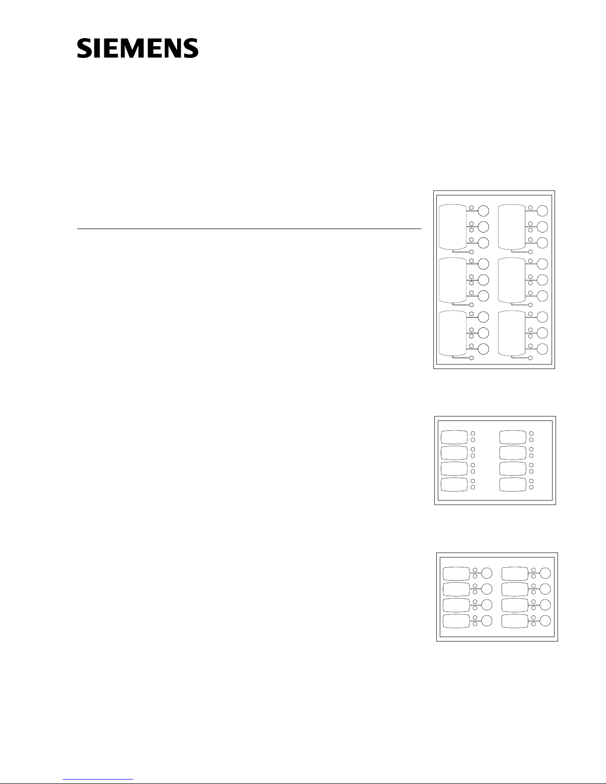
PRE-INSTALLATION Set the board address for each FCM/LCM/SCM using both of the ten-position rotary
switches located on the back of the board (See Figure 5). Each of these addresses
must be a sub-address of the NIC and must be the same as the addresses assigned
in the Zeus Programming Tool. The CSB does not require address setting.
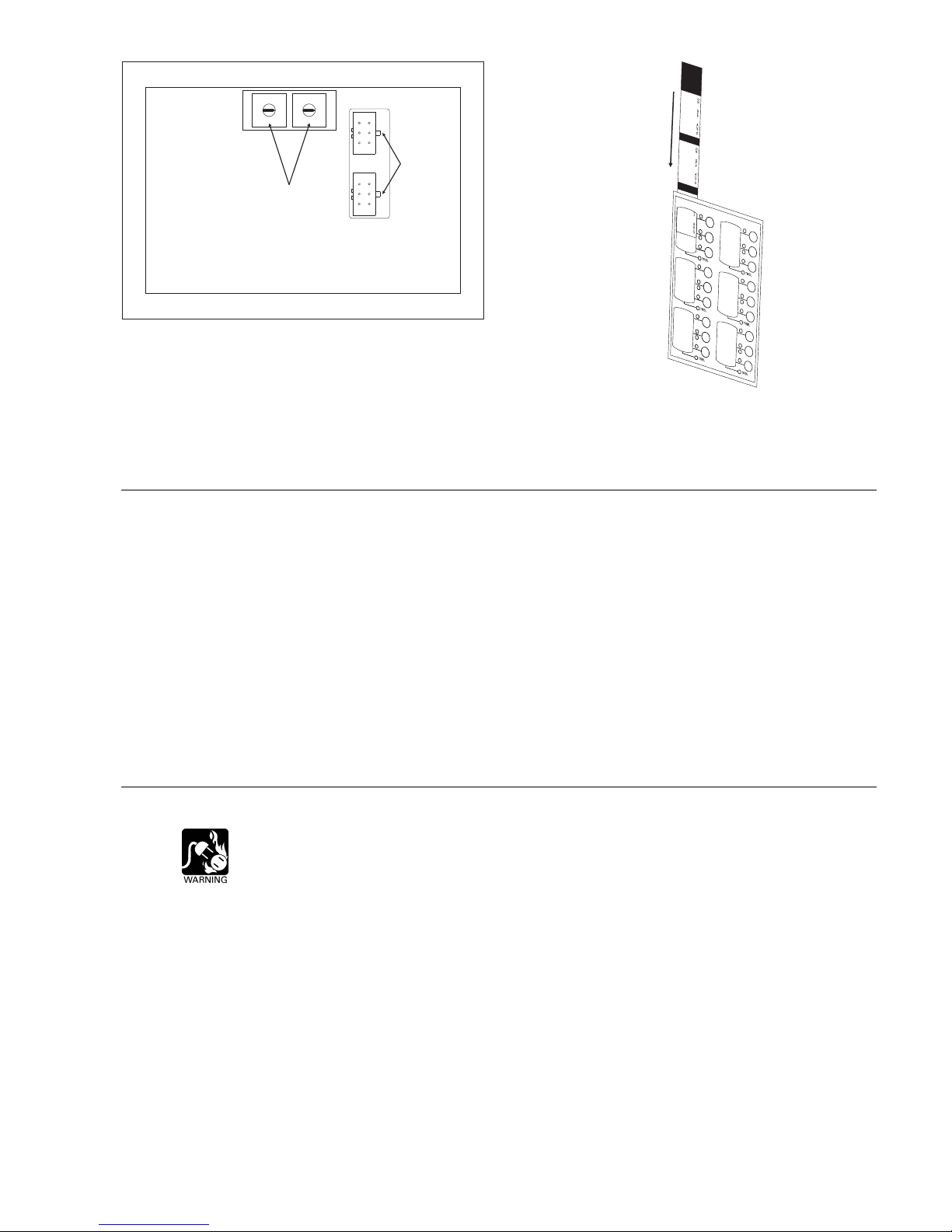
After setting the address, label each switch or LED. When viewed from the front
panel of the FCM/LCM/SCM, the labels are on the left and the control switches and
LEDs are on the right.
• Refer to the Zeus configuration for the address of each module and its
assigned functions.
• Remove the label strip from its slot, and type or print a brief function
identifier for each switch.
• After completing the label strip, insert in back into its slot (See Figure 6).
Siemens Industry, Inc.
Building Technologies Division
P/N 315-035800-22
8
8
7
7
6
5
4
ADDRESS SWITCHES
9
0
1
2
3
ROTARY
9
6
0
5
1
4
2
3
P1
PLUG-IN
CABLE
CONNECTION
P2
Figure 5
FCM-6S, LCM-8S , SCM-8S Address Switches And
Figure 6
Inserting A Label Into The Back Of The FCM-6S
Cable Connections
INSTALLATION
CAN Sounder Board The CSB is normally positioned at the last FCM, LCM or SCM. If desired, multiple
CSBs can be installed. The CSB mounts on the stud of the FCM/LCM/SCM module
that it connects to.
1. Determine the position of the CSB. (This is normally at the last FCM, LCM
or SCM module.)
2. If necessary, remove nut from stud of FCM/LCM/SCM where CSB is to be
mounted.
2. Place mounting hole on the CSB over stud.
3. Secure with nut supplied with FCM/LCM/SCM.
WIRING (Refer to Figure 7.)
Remove ELECTRICAL POWER prior to working on equipment.
Siemens Industry, Inc.
Building Technologies Division
• Each FCM/LCM/SCM module is a node in the CAN bus.
• Each FCM/LCM/SCM connects through the CC-5/CC-2 CAN bus via a
plug-in cable to the NIC or to another FCM/LCM/SCM module.
• Up to 99 FCM/LCM/SCM modules, in any combination, can be connected
to the CAN bus of each NIC.
• Each FCM/LCM/SCM/CSB module is shipped with one CCS cable.
P/N 315-035800-23
 Loading...