

Siemens SCALANCE XR524-8C, SCALANCE XR552-12M, SCALANCE XR528-6M Operating Instructions Manual

SCALANCE XR-500
___________________
___________________
___________________
___________________
___________________
___________________
___________________
___________________
___________________
___________________
SIMATIC NET
Industrial Ethernet switches
SCALANCE XR-500
Operating Instructions
05/2014
A5E03275845
Introduction
1
Safety notes
2
Description of the device
3
Assembling
4
Connecting
5
Uninstalling
6
Upkeep and maintenance
7
Technical data
8
Dimension drawings
9
Certification
10
-05
Siemens AG
Industry Sector
Postfach 48 48
90026 NÜRNBERG
GERMANY
Order number: A5E03275845
Ⓟ
Copyright © Siemens AG 2011 - 2014.
All rights reserved
Legal information
Warning notice system
DANGER
indicates that death or severe personal injury will result if proper precautions are not taken.
WARNING
indicates that death or severe personal injury may result if proper precautions are not taken.
CAUTION
indicates that minor personal injury can result if proper precautions are not taken.
NOTICE
indicates that property damage can result if proper precautions are not taken.
Qualified Personnel
personnel qualified
Proper use of Siemens products
WARNING
Siemens products may only be used for the applications described in the catalog and in the relevant technical
maintenance are required to ensure that the products operate safely and without any problems. The permissible
Trademarks
Disclaimer of Liability
This manual contains notices you have to observe in order to ensure your personal safety, as well as to prevent
damage to property. The notices referring to your personal safety are highlighted in the manual by a safety alert
symbol, notices referring only to property damage have no safety alert symbol. These notices shown below are
graded according to the degree of danger.
If more than one degree of danger is present, the warning notice representing the highest degree of danger will
be used. A notice warning of injury to persons with a safety alert symbol may also include a warning relating to
property damage.
The product/system described in this documentation may be operated only by
task in accordance with the relevant documentation, in particular its warning notices and safety instructions.
Qualified personnel are those who, based on their training and experience, are capable of identifying risks and
avoiding potential hazards when working with these products/systems.
Note the following:
for the specific
documentation. If products and components from other manufacturers are used, these must be recommended
or approved by Siemens. Proper transport, storage, installation, assembly, commissioning, operation and
ambient conditions must be complied with. The information in the relevant documentation must be observed.
All names identified by ® are registered trademarks of Siemens AG. The remaining trademarks in this publication
may be trademarks whose use by third parties for their own purposes could violate the rights of the owner.
We have reviewed the contents of this publication to ensure consistency with the hardware and software
described. Since variance cannot be precluded entirely, we cannot guarantee full consistency. However, the
information in this publication is reviewed regularly and any necessary corrections are included in subsequent
editions.
05/2014 Subject to change

Table of contents
1 Introduction................................................................................................................................... 5
2 Safety notes ................................................................................................................................. 9
3 Description of the device .............................................................................................................. 11
4 Assembling ................................................................................................................................. 29
5 Connecting ................................................................................................................................. 45
3.1 Product overview .................................................................................................................... 11
3.2 SELECT/SET button .............................................................................................................. 16
3.3 LED display ............................................................................................................................ 18
3.3.1 The "RM" LED for the "redundancy manager" function ............................................................ 18
3.3.2 The "SB" LED for the standby function ................................................................................... 18
3.3.3 The "F" LED for the fault status .............................................................................................. 19
3.3.4 "DM1" and "DM2" LEDs for the display mode ......................................................................... 19
3.3.5 "L1" and "L2" LEDs for the power supply ................................................................................ 20
3.3.6 Port P1, P2, ... LEDs for the port status .................................................................................. 22
3.4 C-PLUG / KEY-PLUG ............................................................................................................. 24
3.4.1 Function of the C-PLUG/KEY-PLUG ....................................................................................... 24
3.4.2 Removal and insertion of the C-PLUG/KEY-PLUG ................................................................. 25
3.5 Combo ports .......................................................................................................................... 27
4.1 Safety notices for installation .................................................................................................. 29
4.2 Types of installation ................................................................................................................ 31
4.3 19" rack mounting .................................................................................................................. 31
4.4 Desktop operation with adhesive feet ..................................................................................... 33
4.5 Four-point mounting ............................................................................................................... 34
4.6 Plugging and pulling MM900 media modules .......................................................................... 36
4.7 Inserting and removing media pluggable transceivers ............................................................. 40
4.7.1 Notes on inserting/removing pluggable transceivers ............................................................... 40
4.7.2 Inserting an SFP / SFP+ transceiver ....................................................................................... 41
4.7.3 Removing an SFP / SFP+ transceiver..................................................................................... 41
4.8 Mounting power supply units .................................................................................................. 42
4.8.1 19" rack mounting of the PS598-1 power supply unit .............................................................. 42
4.8.2 Mounting the PS598-1 power supply unit on the rear panel of modular device ........................ 43
5.1 Commissioning....................................................................................................................... 45
5.2 24 VDC power supply ............................................................................................................. 48
5.3 100 to 240 VAC power supply ................................................................................................ 50
5.3.1 Power supply for a SCALANCE XR524-8C ............................................................................. 50
SCALANCE XR-500
Operating Instructions, 05/2014, A5E03275845-05
3

Table of contents
6 Uninstalling ................................................................................................................................ 65
7 Upkeep and maintenance ............................................................................................................ 67
8 Technical data ............................................................................................................................ 75
9 Dimension drawings .................................................................................................................... 83
10 Certification ................................................................................................................................ 93
Index ......................................................................................................................................... 99
5.3.2 Power supply using the PS598-1 power supply unit .................................................................52
5.3.2.1 Connectors of the PS598-1 power supply unit .........................................................................52
5.3.2.2 LED display of the PS598-1 power supply unit.........................................................................56
5.4 Signaling contact .....................................................................................................................57
5.5 Serial interface ........................................................................................................................59
5.6 Out-of-band interface ..............................................................................................................61
5.7 Block architecture of the XR552-12M ......................................................................................62
5.8 Functional ground ...................................................................................................................63
7.1 Changing the fan unit ..............................................................................................................67
7.2 Changing the filter pad ............................................................................................................70
7.3 Downloading new firmware using TFTP without WBM and CLI ................................................72
7.4 Restoring the factory settings ..................................................................................................73
8.1 Technical specifications of the SCALANCE XR524-8C ............................................................75
8.2 Technical specifications of the SCALANCE XR528-6M ............................................................78
8.3 Technical specifications of the SCALANCE XR552-12M ..........................................................80
8.4 Switching properties ................................................................................................................82
9.1 SCALANCE XR524-8C ...........................................................................................................83
9.2 SCALANCE XR528-6M ...........................................................................................................84
9.3 SCALANCE XR552-12M .........................................................................................................85
9.4 Mounting brackets for use on ships .........................................................................................86
10.1 FDA and IEC marks ................................................................................................................97
10.2 Mechanical stability (in operation) ............................................................................................98
SCALANCE XR-500
4 Operating Instructions, 05/2014, A5E03275845-05

1
Purpose of the Operating Instructions
Validity of the Operating Instructions
Designations used
Classification
Description
Terms used
SCALANCE XR-500 is used.
SCALANCE XR552-12M
added to it in brackets.
(2 x 24 VDC)
Documentation on configuration
These operating instructions support you when installing and connecting up devices of the
SCALANCE XR-500 product line.
The configuration and the integration of the device in a network are not described in these
operating instructions.
These operating instructions apply to the following devices:
● SCALANCE XR524-8C
● SCALANCE XR528-6M
● SCALANCE XR552-12M
Product line If information applies to all product groups within the product line, the term
Device If information relates to a specific device, the device name is used. SCALANCE XR524-8C
Variant For a variant of the device, the device name has the appropriate variant
SCALANCE XR-500
SCALANCE XR528-6M
SCALANCE XR524-8C
You will find detailed information on configuring the devices in the following configuration
manuals:
● SCALANCE XM-400/XR-500 Web Based Management
● SCALANCE XM-400/XR-500 Command Line Interface
SCALANCE XR-500
Operating Instructions, 05/2014, A5E03275845-05
5

Introduction
Further documentation
SIMATIC NET manuals
You will find the configuration manuals here:
● On the data medium that ships with some products:
– Product CD / product DVD
– SIMATIC NET Manual Collection
● On the Internet pages of Siemens Industry Online Support.
(http://support.automation.siemens.com/WW/view/en/48803858/130000
)
In the system manuals "Industrial Ethernet / PROFINET Industrial Ethernet" and "Industrial
Ethernet / PROFINET passive network components", you will find information on other
SIMATIC NET products that you can operate along with the devices of this product line in an
Industrial Ethernet network.
There, you will find among other things optical performance data of the communications
partner that you require for the installation.
You will find the system manuals here:
● On the data medium that ships with some products:
– Product CD / product DVD
– SIMATIC NET Manual Collection
● On the Internet pages of Siemens Industry Online Support under the following entry IDs:
– 27069465 (http://support.automation.siemens.com/WW/view/en/27069465
– 84922825 (http://support.automation.siemens.com/WW/view/en/84922825)
You will find SIMATIC NET manuals on the Internet pages of Siemens Industry Online
Support:
● using the search function:
Link to Siemens Industry Online Support
(http://support.automation.siemens.com/WW/view/en
Enter the entry ID of the relevant manual as the search item.
● In the navigation panel on the left hand side in the area "Industrial Communication":
Link to the area "Industrial Communication"
(http://support.automation.siemens.com/WW/view/en/10805878/130000
)
Industrial Ethernet / PROFINET Industrial Ethernet System Manual
Industrial Ethernet / PROFINET - Passive network components System Manual
)
)
Go to the required product group and make the following settings:
tab "Entry list", Entry type "Manuals"
SCALANCE XR-500
6 Operating Instructions, 05/2014, A5E03275845-05

Introduction
SIMATIC NET glossary
Catalogs
Security information
You will find the documentation for the SIMATIC NET products relevant here on the data
medium that ships with some products:
● Product CD / product DVD
● SIMATIC NET Manual Collection
Explanations of many of the specialist terms used in this documentation can be found in the
SIMATIC NET glossary.
You will find the SIMATIC NET glossary here:
● SIMATIC NET Manual Collection or product DVD
The DVD ships with certain SIMATIC NET products.
● On the Internet under the following entry ID:
You will find the order numbers for the Siemens products of relevance here in the following
catalogs:
● SIMATIC NET Industrial Communication / Industrial Identification, catalog IK PI
● SIMATIC Products for Totally Integrated Automation and Micro Automation, catalog
● Industry Mall - catalog and ordering system for automation and drive technology, Online
You can request the catalogs and additional information from your Siemens representative.
Siemens provides products and solutions with industrial security functions that support the
secure operation of plants, solutions, machines, equipment and/or networks. They are
important components in a holistic industrial security concept. With this in mind, Siemens’
products and solutions undergo continuous development. Siemens recommends strongly
that you regularly check for product updates.
For the secure operation of Siemens products and solutions, it is necessary to take suitable
preventive action (e.g. cell protection concept) and integrate each component into a holistic,
state-of-the-art industrial security concept. Third-party products that may be in use should
also be considered. For more information about industrial security, visit
http://www.siemens.com/industrialsecurity
50305045 (http://support.automation.siemens.com/WW/view/en/50305045
ST 70
catalog
.
)
To stay informed about product updates as they occur, sign up for a product-specific
newsletter. For more information, visit http://support.automation.siemens.com
SCALANCE XR-500
Operating Instructions, 05/2014, A5E03275845-05
.
7

Introduction
Unpacking and checking
WARNING
Do not use any parts that show evidence of damage
If you use damaged parts, there is no guarantee that the device will function according to
the specification.
If you use damaged parts, this can lead to the following problems:
• Injury to persons
• Loss of the approvals
• Violation of the EMC regulations
• Damage to the device and other components
Use only undamaged parts.
1. Make sure that the package is complete.
2. Check all the parts for transport damage.
SCALANCE XR-500
8 Operating Instructions, 05/2014, A5E03275845-05
2
Read the safety notices
General notices
WARNING
Restricted use of the device
WARNING
Maximum ambient temperature
WARNING
Suitable installation location
Note the following safety notices. These relate to the entire working life of the device.
You should also read the safety notices relating to handling in the individual sections,
particularly in the sections "Installation" and "Connecting up".
Devices of the SCALANCE XR-500 product line must not be put into operation in nuclear
power plants or other nuclear facilities.
The operating temperature of a device of the SCALANCE XR-500 product line depends on
the ambient temperature.
For SCALANCE XR524-8C, the ambient temperature must not exceed 70 °C.
For SCALANCE XR528-6M and SCALANCE XR552-12M, the ambient temperature must
not exceed 60 °C.
The installation location of a device of the SCALANCE XR-500 product line must be
selected so that only qualified service personnel or trained users have access to it.
Operation of a device of the SCALANCE XR-500 product line is permitted only when these
requirements are met.
SCALANCE XR-500
Operating Instructions, 05/2014, A5E03275845-05
9
Safety notes
NOTICE
Suitable fusing for the power supply cables
Safety notices on use in hazardous areas
General safety notices relating to protection against explosion
WARNING
Opening the device
Safety notices when using the device according to Hazardous Locations (HazLoc)
The current on the terminal may not exceed 25 A. Use a fuse, that protects against currents
> 25 A. The fuse must meet the following requirements:
In areas according to NEC or CEC:
• Suitable for DC (min. 60 V / 25 A)
• Breaking current at least 10 kA
• Approval according to ANSI/UL 248-1
• Suitable for the protection of DC power supply circuits
In other areas:
• Suitable for DC (min. 60 V / 25 A)
• Breaking current at least 10 kA
• Approval in compliance with IEC 60127-1 / EN 601127-1
• Breaking characteristics: B or C for circuit breakers and fuses
• Suitable for the protection of DC power supply circuits
Do not open when energized. Note that this does not apply to opening the service panel in
the housing.
If you use the device under HazLoc conditions you must also keep to the following safety
notices in addition to the general safety notices for protection against explosion:
This equipment is suitable for use in Class I, Division 2, Groups A, B, C and D or nonhazardous locations only.
This equipment is suitable for use in Class I, Zone 2, Group IIC or non-hazardous locations
only.
SCALANCE XR-500
10 Operating Instructions, 05/2014, A5E03275845-05
3
3.1
Product overview
Order numbers
Device
Order number
Description
the front
the front, layer 3 without KEY-PLUG
supply on the rear, layer 3 without KEY-PLUG
supply on the rear, layer 3 without KEY-PLUG
6GK5 528-0AA00-2HR2
2, height units, 6 modules, cable outlet at rear
6GK5 528-0AR00-2HR2
2 height units, 6 modules, cable outlet rear, layer 3 without KEY-PLUG
6GK5 552-0AA00-2AR2
3, height units, 12 modules
6GK5 552-0AA00-2HR2
3, height units, 12 modules, cable outlet at rear
6GK5 552-0AR00-2AR2
3 height units, 12 modules, layer 3 without KEY-PLUG
6GK5 552-0AR00-2HR2
3 height units, 12 modules, cable outlet rear, layer 3 without KEY-PLUG
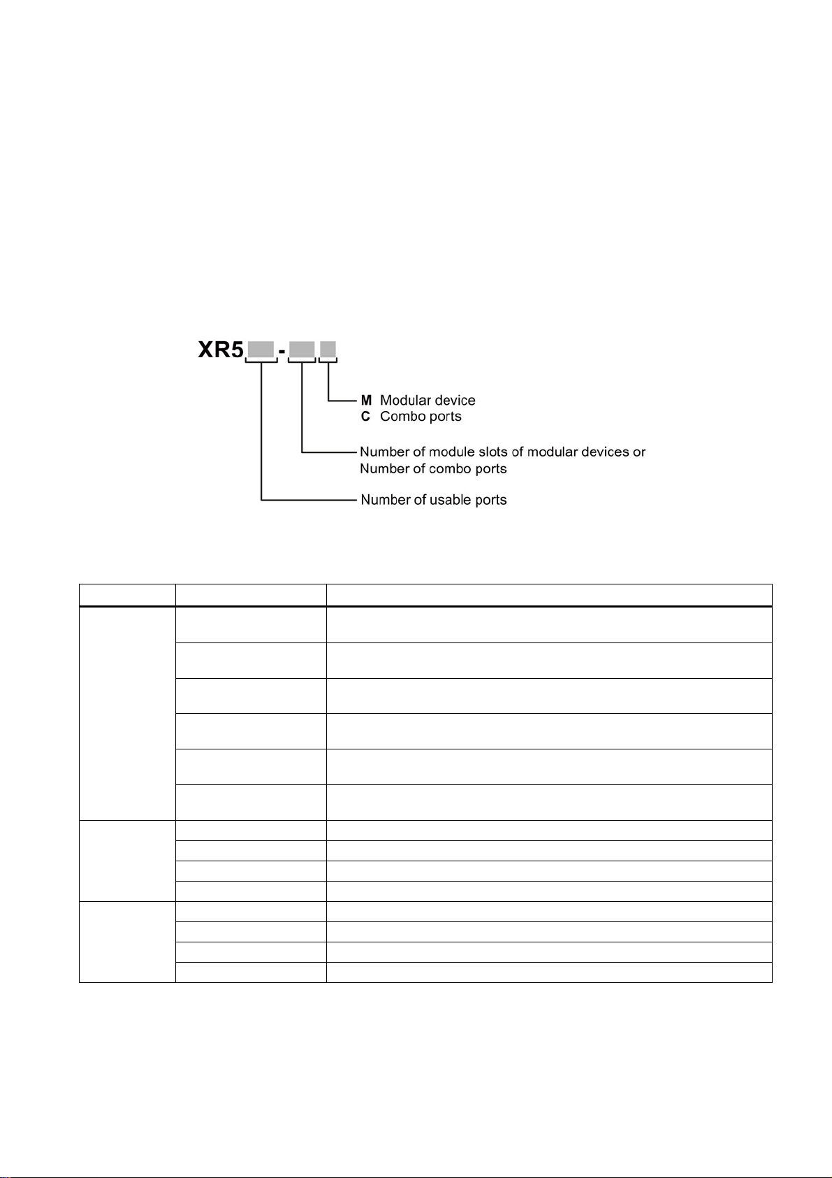
The type designation of a SCALANCE XR-500 IE switch is made up of several parts that
have the following meaning:
XR524-8C 6GK5 524-8GS00-2AR2 1 height unit, 8 combo ports, 2 x 24 VDC, connector for the power supply on
6GK5 524-8GR00-2AR2 1 height unit, 8 combo ports, 2 x 24 VDC, connector for the power supply on
6GK5 524-8GS00-3AR2 1 height unit, 8 combo ports, 1 x 100 to 240 VAC, connector for the power
supply on the rear
6GK5 524-8GR00-3AR2 1 height unit, 8 combo ports, 1 x 100 to 240 VAC, connector for the power
6GK5 524-8GS00-4AR2 1 height unit, 8 combo ports, 2 x 100 to 240 VAC, connector for the power
supply on the rear
6GK5 524-8GR00-4AR2 1 height unit, 8 combo ports, 2 x 100 to 240 VAC, connector for the power
XR528-6M 6GK5 528-0AA00-2AR2 2, height units, 6 modules
6GK5 528-0AR00-2AR2 2 height units, 6 modules, layer 3 without KEY-PLUG
XR552-12M
SCALANCE XR-500
Operating Instructions, 05/2014, A5E03275845-05
11

Description of the device
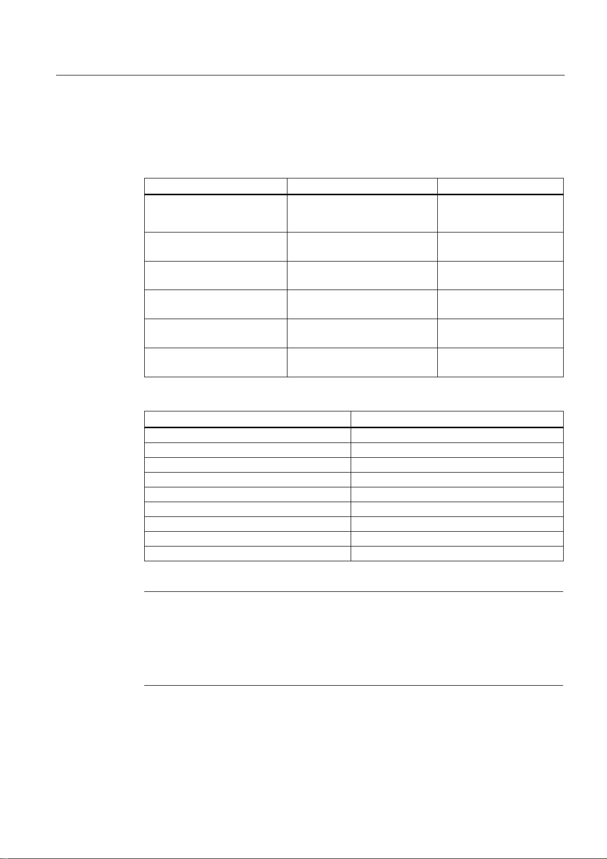
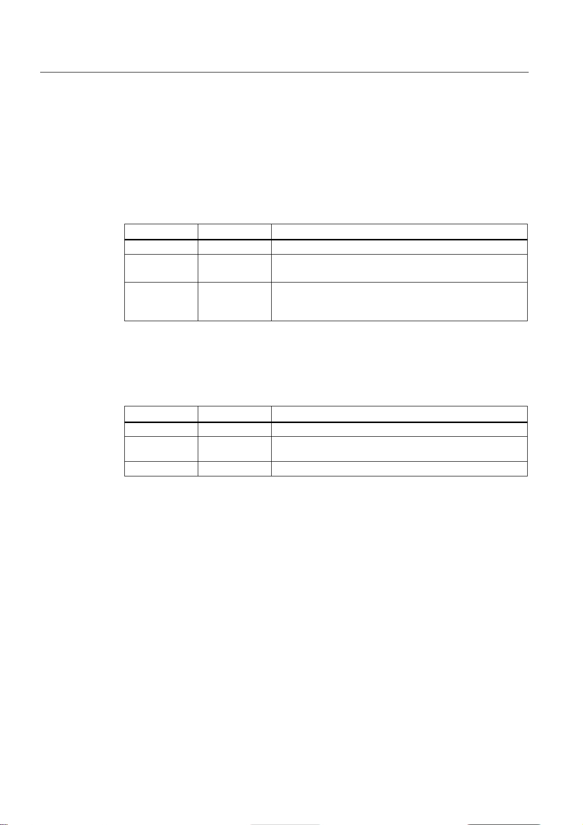
Interfaces
Device
Total
usable
ports
Number of
slots for media
modules
Modular ports
using module
slots
Pluggable transceiver
slots
Electrical
connectors
Combo ports
SFP
SFP+
XR524-8C
24 - - 8 -
24 8 XR528-6M
28 6 24 - 4 - -
XR552-12M
52
12
48 - 4 - -
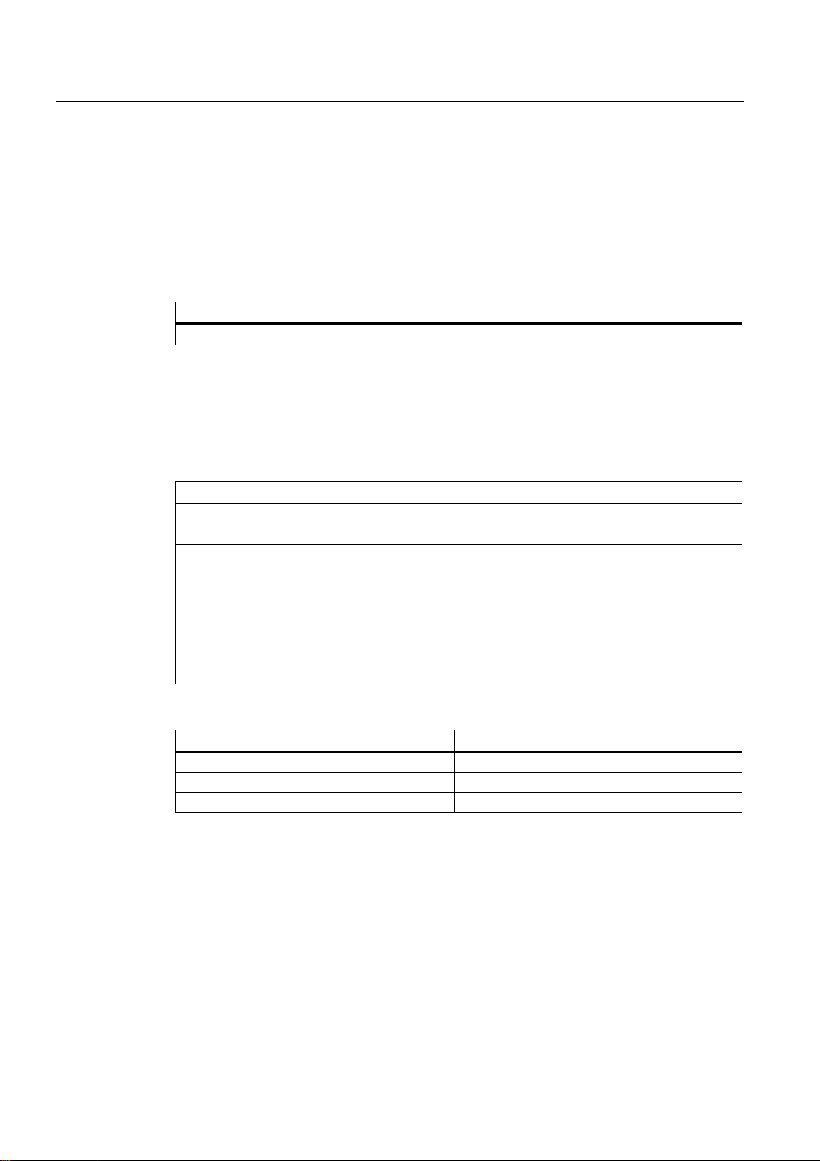
Components of the product
SCALANCE XR524-8C
SCALANCE XR528-6M
SCALANCE XR552-12M
C-PLUG
software
2 brackets for 19" rack installation
● ● ●
Drive: Torx
Drive: Torx
Drive: Torx
mounting the power supply units (M3 x 6
countersunk, drive: Torx)
contact
connector
Fan unit
-
FAN597-2
FAN597-1
Filter frame with filter pad
- ● ●
Covers for the interfaces of the SFP+
8 4 4
media module slots
the MM900 media modules in use
Note
When the modules ship, the media module slots are fitted with dummy covers.
Note
You will find detailed i
product DVD.
3.1 Product overview
The following components ship with a SCALANCE XR-500:
Device with exchangeable medium
Product DVD with documentation and
8 screws for mounting the fixing
brackets for 19" rack installation
4 adhesive feet for desktop operation ● ● ●
2 mounting plates and 24 screws for
4-pin terminal block for the 24 VDC
power supply
2-pin terminal block for the signaling
Connecting cable for the serial interface
with RJ-11 plug and 9-pin D-sub female
Dummy covers for the interfaces of the
● ● ●
● ● ●
M3 x 5 countersunk,
- ● ●
With variants with
24 VDC
● ● ●
● ● ●
- 6 12
M3 x 6 countersunk,
● ●
M3 x 6 countersunk,
Labels for the slot numbers to identify
- ● ●
nformation on these products in the operating instructions on the
SCALANCE XR-500
12 Operating Instructions, 05/2014, A5E03275845-05
Description of the device
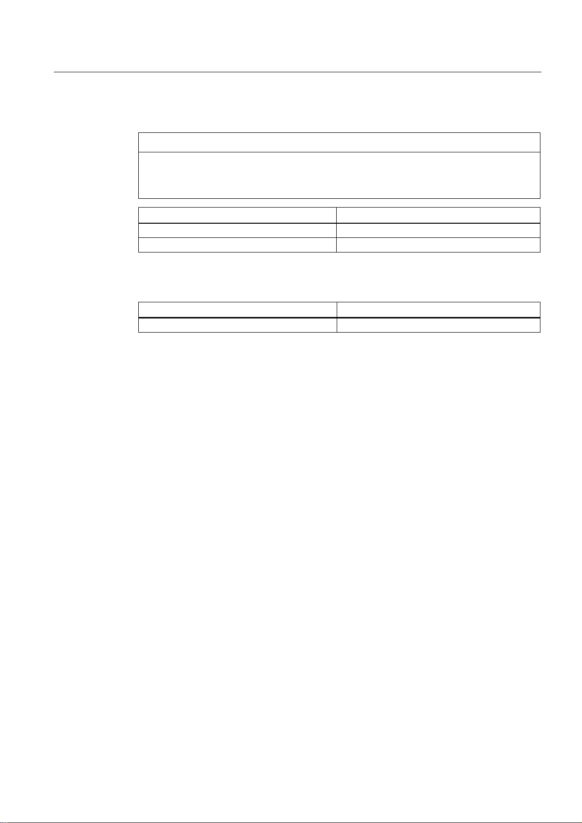
Accessories for the SCALANCE XR-500 product line
Power cable
Type
Description
Order number
Austria, Finland
100 to 240 VAC, straight, 3 m
100 to 240 VAC, straight, 3 m
100 to 240 VAC, straight, 3 m
100 to 240 VAC, straight, 3 m
100 to 240 VAC, straight, 3 m
SFP transceiver
Type
Order number
SFP991-LD *
6GK5 991-1AF00-8AA0
SFP991-1ELH200 *
6GK5 991-1AE30-8AA0
SFP992-1LD
6GK5 992-1AM00-8AA0
SFP992-1LH
6GK5 992-1AN00-8AA0
SFP992-1LH+
6GK5 992-1AP00-8AA0
SFP992-1ELH
6GK5 992-1AQ00-8AA0
* Cannot be operated in SFP+ slots.
Note
Restriction for pluggable transceivers for SCALANCE XR524-8C (2 x 24 VDC)
If you use
(2 x 24 VDC), the maximum ambient temperature is reduced to 60
For the values of the ambient temperature without pluggable transceivers, refer to the
section "
3.1 Product overview
The following accessories are available for the SCALANCE XR-500 product line:
Power cable
100 to 240 VAC, straight, 3 m
Power cable
Power cable
Power cable
Power cable
Power cable
For Germany, France, Spain,
Netherlands, Belgium, Sweden,
For Great Britain 6ES7 900-0BA00-0XA0
For Switzerland 6ES7 900-0CA00-0XA0
For America 6ES7 900-0DA00-0XA0
For Italy 6ES7 900-0EA00-0XA0
For China 6ES7 900-0FA00-0XA0
SFP991-1 * 6GK5 991-1AD00-8AA0
SFP991-LH+ * 6GK5 991-1AE00-8AA0
SFP992-1 6GK5 992-1AL00-8AA0
6ES7 900-0AA00-0XA0
transceivers of the types LH, LH+, ELH or ELH200 with a SCALANCE XR524-8C
Technical data (Page 75)".
SCALANCE XR-500
Operating Instructions, 05/2014, A5E03275845-05
℃.
13
Description of the device
Note
No far-end fault detection for an SFP transceiver in the SFP+ slot
If you use an SFP transceiver in an SFP+ slot, no far
interface.
KEY-PLUG
Type
Order number
KEY-PLUG XR-500
6GK5 905-0PA00
Accessories for the devices SCALANCE XR528-6M and SCALANCE XR552-12M
Media modules
Type
Order number
MM991-4
6GK5 991-4AB00-8AA0
MM991-4LD
6GK5 991-4AC00-8AA0
MM992-4
6GK5 992-4AL00-8AA0
MM992-4LD
6GK5 992-4AM00-8AA0
MM992-4CUC
6GK5 992-4GA00-8AA0
MM992-4PoE
6GK5 992-4QA00-8AA0
MM992-4PoEC
6GK5 992-4RA00-8AA0
MM992-4SFP
6GK5 992-4AS00-8AA0
SFP+ transceiver
Type
Order number
SFP993-1
6GK5 993-1AT00-8AA0
SFP993-1LD
6GK5 993-1AU00-8AA0
SFP993-1LH
6GK5 993-1AV00-8AA0
3.1 Product overview
-end fault detection is possible for this
The following additional accessories are available for devices SCALANCE XR528-6M and
SCALANCE XR552-12M:
MM992-4CU 6GK5 992-4SA00-8AA0
SCALANCE XR-500
14 Operating Instructions, 05/2014, A5E03275845-05
Description of the device
Fan unit
NOTICE
Operation only with fan unit
Type
Order number
FAN597-1 for SCALANCE XR552-12M
6GK5 597-1AA00-8AA0
FAN597-2 for SCALANCE XR528-6M
6GK5 597-2AA00-8AA0
Power supply units
Type
Order number
PS598-1 (100 to 240 VAC / 300 W)
6GK5 598-1AA00-3AA0
3.1 Product overview
Use the devices SCALANCE XR528-6M and SCALANCE XR552-12M only with a correctly
fitted fan unit. Operation without the fan is not possible and would damage the device.
The power supply units allow operation with input voltages of 100 to 240 VAC.
SCALANCE XR-500
Operating Instructions, 05/2014, A5E03275845-05
15
Description of the device
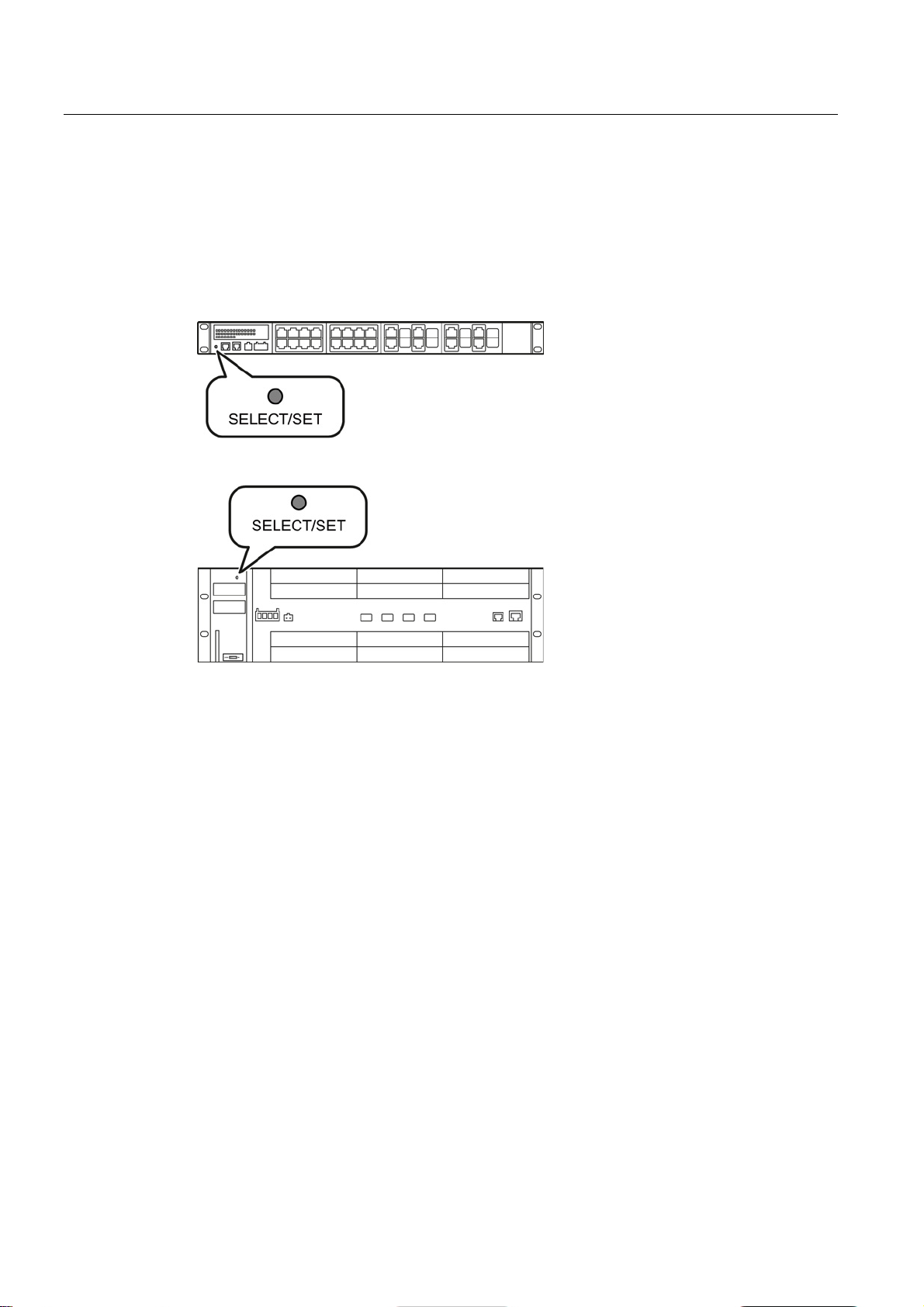
3.2
SELECT/SET button
Position
Setting the display mode
Resetting the device to factory defaults
3.2 SELECT/SET button
With a SCALANCE XR-500, the "SELECT/SET" button is on the front of the housing. The
"SELECT/SET" button has several functions that are described below.
Figure 3-1 SELECT/SET button on the SCALANCE XR524-8C
Figure 3-2 SELECT/SET button on the SCALANCE XR552-12M SCALANCE XR528-6M is
analogous.
By pressing the button briefly, you change to the display mode of the LED display. You will
find detailed information on the display modes in the sections ""DM1" and "DM2" LEDs for
the display mode (Page 19)" and "Port P1, P2, ... LEDs for the port status (Page 22)".
If you reset, all the changes you have made will be overwritten by factory defaults.
To reset the device to the factory defaults, follow the steps below:
1. Switch to display mode A.
Display mode A is active when the LEDs "DM1" and "DM2" are off.
When the LEDs "DM1" and "DM2" are lit or flashing, you need to press the
"SELECT/SET" button several times briefly until the "DM1" and "DM2" LEDs are off.
If you do not press the "SELECT/SET" button for longer than 1 minute, the device
automatically switches to display mode A.
2. Hold down the "SELECT/SET" button for 12 seconds.
After 9 seconds, the "DM1" and "DM2" LEDs start to flash for 3 seconds. At the same
time, the port LEDs light up one after the other.
If you release the button before the 12 seconds have elapsed, the reset is canceled.
SCALANCE XR-500
16 Operating Instructions, 05/2014, A5E03275845-05

Description of the device
CAUTION
Restart with the SELECT/SET button disabled for "Restore Factory Defaults"
Defining the fault mask
Enabling/disabling the redundancy manager
Initial situation:
Result:
Initial situation:
Result:
3.2 SELECT/SET button
If you have disabled the SELECT/SET button for "Restore Factory Defaults" in the
configuration, this does not apply during the startup phase. When you restart after cycling
power, the configuration can nevertheless be deleted using this button. This action cannot
be undone and you then need to reload the device configuration. This can lead to
disturbances and failures in the corresponding network area.
Using the fault mask, you specify an individual "good status" for the connected ports and the
power supply. Deviations from this status are displayed as errors/faults.
To define the fault mask, follow the steps below:
1. Change to display mode D.
Display mode D is active when the "DM1" and "DM2" LEDs are lit green.
If a different display mode is active, press the "SET/SELECT" button several times briefly,
until the "DM1" and "DM2" LEDs are lit green.
2. Hold down the "SELECT/SET" button for 5 seconds.
After 2 seconds, the "DM1" and "DM2" LEDs start to flash for 3 seconds. At the same
time the port LEDs go on one after the other.
After you have pressed the button for 5 seconds, the current settings are stored as the
"good status".
If you release the button before the 5 seconds are up, the previous fault mask is retained.
To enable/disable the redundancy manager, follow the steps below:
1. Change to display mode B.
Display mode B is active when the "DM1" LED is lit green and the and "DM2" LED is off.
If a different display mode is active, press the "SET/SELECT" button several times briefly,
until the "DM1" LED is lit green and the "DM2" LED is off.
2. Hold down the "SELECT/SET" button for 5 seconds.
After 2 seconds, the "DM1", "DM2" and "RM" LEDs start to flash for 3 seconds. At the
same time, the port LEDs light up one after the other.
If you release the button before the 5 seconds have elapsed, the action is canceled.
The result of the action depends on the initial situation:
–
The redundancy manager and media redundancy are disabled.
After enabling the redundancy manager, media redundancy is also enabled.
–
The redundancy manager and media redundancy are enabled.
After disabling the redundancy manager, media redundancy remains enabled.
SCALANCE XR-500
Operating Instructions, 05/2014, A5E03275845-05
17
Description of the device
3.3
LED display
3.3.1
The "RM" LED for the "redundancy manager" function
LED color
LED status
Meaning
-
Off
The device is not a redundancy manager.
The ring is working without problems, monitoring is activated.
has switched through.
3.3.2
The "SB" LED for the standby function
LED color
LED status
Meaning
-
Off
The standby function is disabled.
passive.
Green
Flashing
The standby function is enabled. The standby section is active.
3.3 LED display
The "RM" LED indicates whether or not the device is a redundancy manager and whether or
not the ring is operating free of error.
Green On The device is a redundancy manager.
Green Flashing The device is a redundancy manager.
An interruption has been detected on the ring and the device
The "SB" LED shows the status of the standby function.
Green On The standby function is enabled. The standby section is
SCALANCE XR-500
18 Operating Instructions, 05/2014, A5E03275845-05
Description of the device
3.3.3
The "F" LED for the fault status
Meaning during device startup
LED color
LED status
Meaning during device startup
-
Off
Device startup was completed successfully.
Red
On
Device startup is not yet completed or errors have occurred.
Red
Flashing
There are errors in the firmware.
Meaning during operation
LED color
LED status
Meaning during operation
-
Off
The device is operating free of errors.
opened.
3.3.4
"DM1" and "DM2" LEDs for the display mode
LED color
LED status
Meaning
DM1 LED
DM2 LED
-
Off
Display mode A
Green
On
Off
Display mode B
Green
Off
On
Display mode C
Green
On
Display mode D
Green
Flashing
Off
Display mode E
3.3 LED display
The "F" LED shows the fault/error status of the device.
Red On The device has detected a problem. The signaling contact has
The "DM1" and "DM2" LEDs indicate which display mode is set.
There are 5 display modes (A, B, C, D, and E). Display mode A is the default mode.
Depending on the set display mode, the "L1", "L2" LEDs and the port LEDs show different
information.
SCALANCE XR-500
Operating Instructions, 05/2014, A5E03275845-05
19
Description of the device
Setting the display mode
Pressing SELECT/SET button
starting at display mode A
LED status
Display mode
DM1
DM2
-
Off
Display mode A
Press once
On
Off
Display mode B
Press twice
Off
On
Display mode C
Press three times
On
Display mode D
Press four times
Flashing
Off
Display mode E
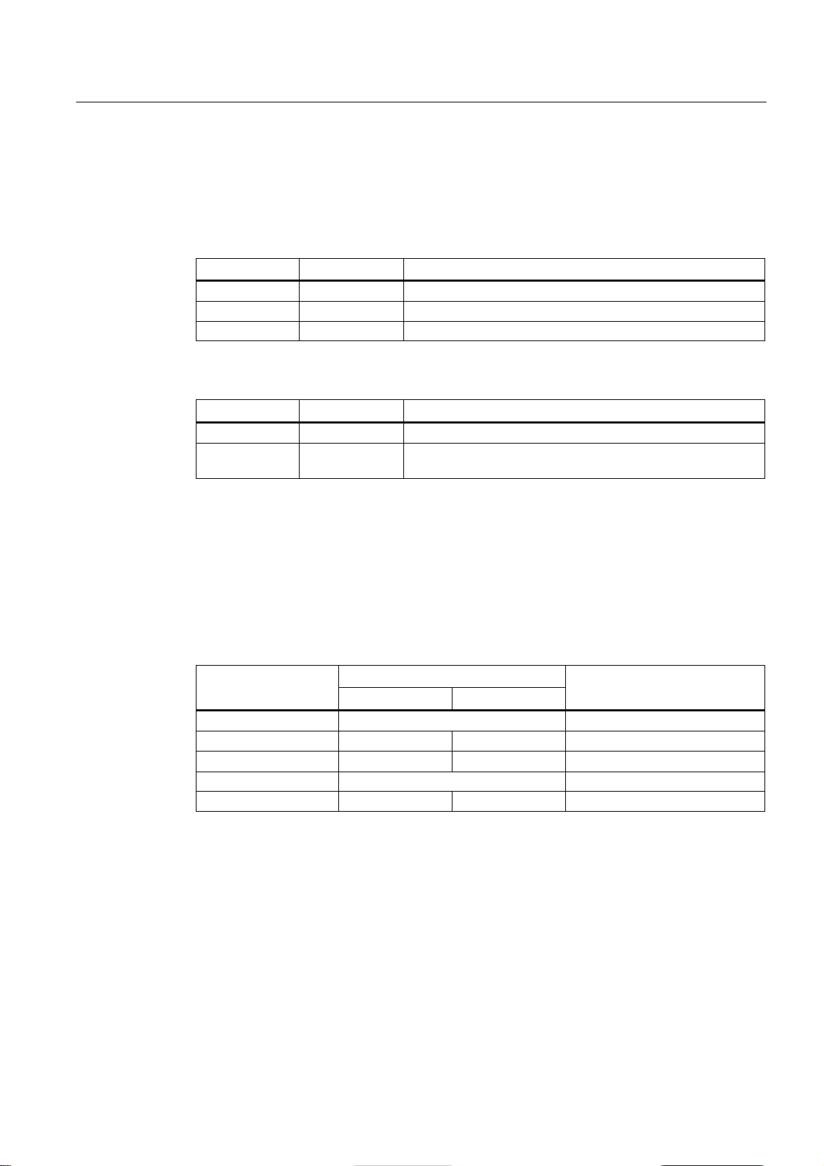
3.3.5
"L1" and "L2" LEDs for the power supply
Voltage limit
Meaning in display modes A, B, C and E
L1/L2 LED
L1/L2 connector
LED color
LED status
-
Off
Power supply lower than 17 VDC
Green
On
Power supply higher than 17 VDC
L1/L2 LED
L1/L2 connector
LED color
LED status
-
Off
Power supply lower than 90 VAC
Green
On
Power supply higher than 90 VAC
3.3 LED display
To set the required display mode, press the "SELECT/SET" button.
If you do not press the "SELECT/SET" button for longer than 1 minute, the device
automatically changes to display mode A.
The "L1" and "L2" LEDs indicate the current range of the power supply at connectors L1 and
L2.
The meaning of the "L1" and "L2" LEDs depends on the set display mode, see section
""DM1" and "DM2" LEDs for the display mode (Page 19)".
For devices with 24 VDC, the voltage limit is 17 VDC.
With devices with 100 to 240 VAC, the voltage limit is 90 VAC.
In display modes A, B, C and D, from the "L1" and "L2" LEDs you can see whether the
power supply is higher or lower than a certain voltage limit.
Table 3- 1 For devices with a 24 VDC power supply
Table 3- 2 Power supply for devices with 100 to 240 VAC
SCALANCE XR-500
20 Operating Instructions, 05/2014, A5E03275845-05
Description of the device
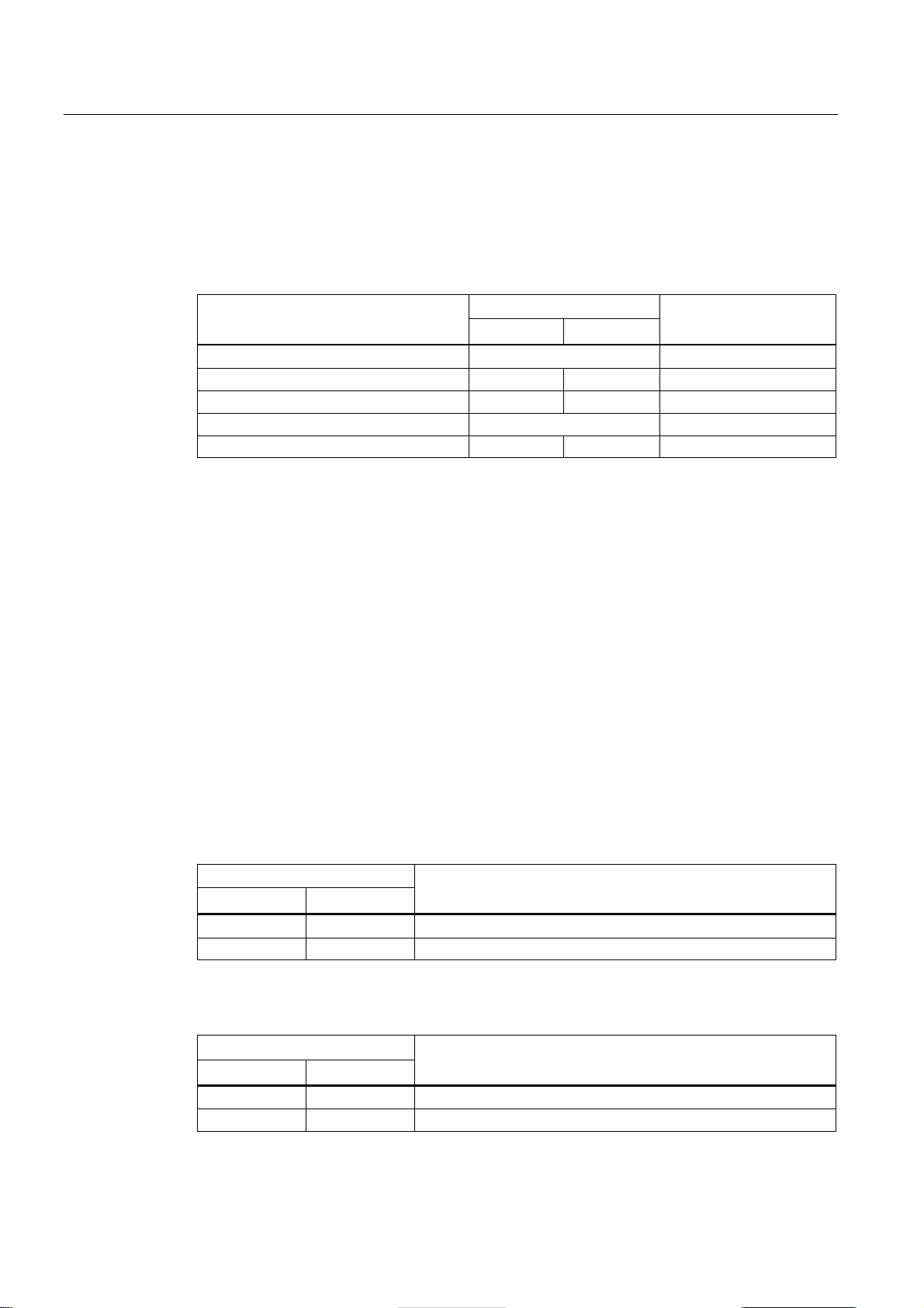
Meaning in display mode D
L1/L2 LED
L1/L2 connector
LED color
LED status
If the power supply falls below 17 VDC, the signaling contact does
not respond.
L1/L2 LED
L1/L2 connector
LED color
LED status
If the power supply falls below 90 VAC, the signaling contact does
responds.
3.3 LED display
In display mode D, the "L1" and "L2" LEDs indicate whether the power supply is monitored.
Table 3- 3 Monitoring for devices with 24 VDC
- Off Power supply is not monitored.
Green On Power supply is monitored.
If the power supply falls below 17 VDC, the signaling contact
responds.
Table 3- 4 Monitoring for devices with 100 to 240 VAC
- Off Power supply is not monitored.
not respond.
Green On Power supply is monitored.
If the power supply falls below 90 VAC, the signaling contact
SCALANCE XR-500
Operating Instructions, 05/2014, A5E03275845-05
21
Description of the device
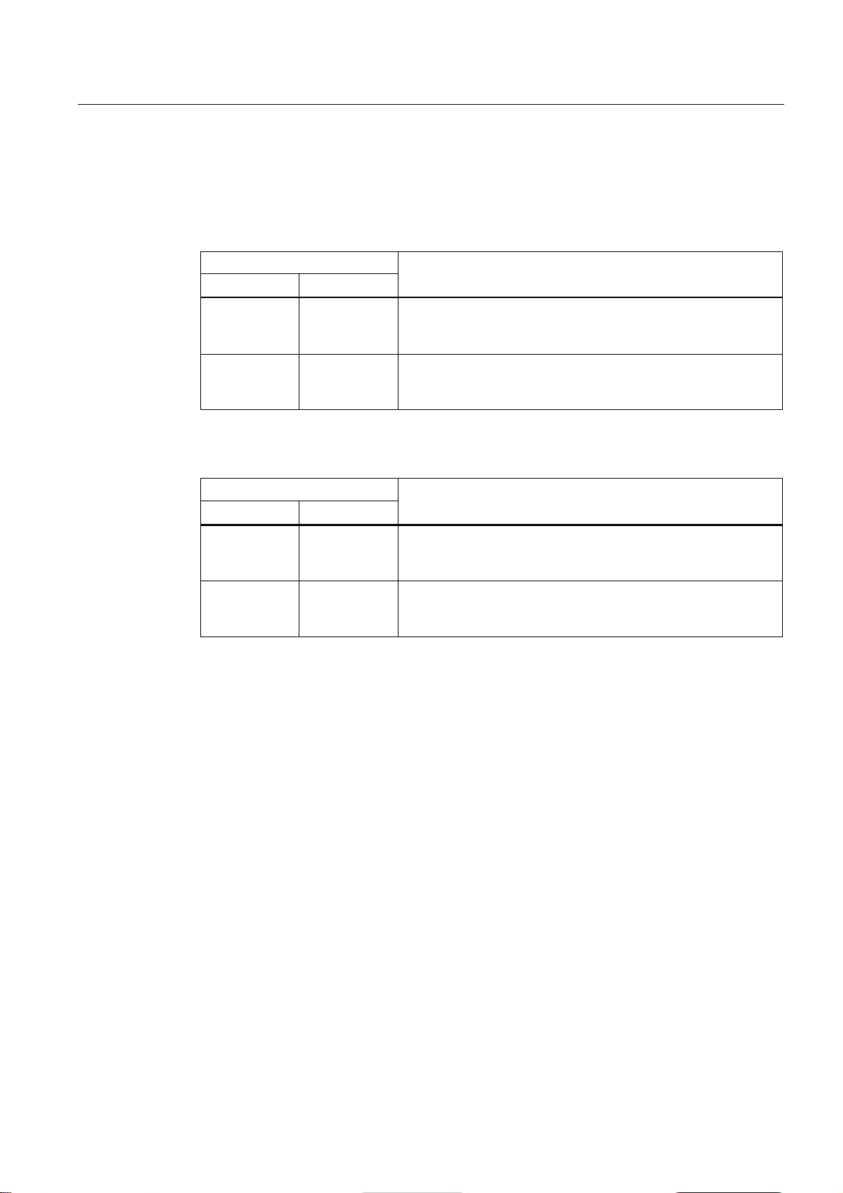
3.3.6
Port P1, P2, ... LEDs for the port status
Meaning in display mode A
LED color
LED status
Meaning
cable not connected).
port can receive and send data.
Link exists and port in "blocking" status. In this status, the
port only receives management data (no user data).
period*
status, no data is sent or received via the port.
port.
Yellow
Flashing / lit
Receiving data at port
Note
LEDS for the SFP+ slots of the SCALANCE XR-500
If SFP+ slots of the SCALANCE XR-500 have SFP transceivers plugged into them, the LEDs
of these slots do not indicate any data transfer.
Meaning in display mode B
LED color
LED status
Meaning
-
Off
Port operating at 10 Mbps
Orange
On
Port operating at 1000 Mbps
Green
Flashing
Port operating at 10 Gbps
3.3 LED display
The port LEDs "P1", "P2" etc. show information about the corresponding ports.
The meaning of the Port LEDs depends on the set display mode, see section ""DM1" and
"DM2" LEDs for the display mode (Page 19)".
In display mode A, the port LEDs indicate whether a valid link exists.
- Off No valid link to the port (for example station turned off or
Green On Link exists and port in normal status. In this status, the
Flashes once per period*
Flashes three times per
Flashes four times per
period*
Link exists and port turned off by management. In this
Link exists and port is in the "monitor port" status. In this
status, the data traffic of another port is mirrored to this
* 1 period ≙ 2.5 seconds
In display mode B, the port LEDs indicate the transmission speed.
Green On Port operating at 100 Mbps
If there is a connection problem and the type of transmission is fixed (autonegotiation off),
the desired status, in other words the set transmission speed (1000 Mbps, 100 Mbps, 10
Mbps) continues to be displayed. If there is a connection problem and autonegotiation is
active, the port LED goes off.
SCALANCE XR-500
22 Operating Instructions, 05/2014, A5E03275845-05
Description of the device
Meaning in display mode C
LED color
LED status
Meaning
-
Off
Port operating in half duplex mode
Meaning in display mode D
LED color
LED status
Meaning
-
Off
Port is not monitored.
plugged in), the signaling contact indicates an error.
indicates an error.
Meaning in display mode E
LED color
LED status
Meaning
-
Off
The connected device is not supplied using PoE.
3.3 LED display
In display mode C, the port LEDs indicate the mode.
Green On Port operating in full duplex mode
In display mode D, the port LEDs indicate whether the port is monitored.
Green On Port is monitored for "Link down".
If no link was established at the port (e.g. cable not
Yellow On Port is monitored for "Link up".
If a link was established at the port, the signaling contact
In display mode E, the port LEDs indicate whether the connected device is supplied using
PoE.
Green On The connected device is supplied via PoE.
SCALANCE XR-500
Operating Instructions, 05/2014, A5E03275845-05
23

Description of the device
3.4
C-PLUG / KEY-PLUG
3.4.1
Function of the C-PLUG/KEY-PLUG
NOTICE
Do not remove or insert a C-PLUG/KEY-PLUG during operation
Saving configuration data and enabling layer 3 functionality
Note
The device can also be operated without a C
How it works
Operating mode
3.4 C-PLUG / KEY-PLUG
A C-PLUG/KEY-PLUG may only be removed or inserted when the device is turned off.
A PLUG is an exchangeable storage medium for storing the configuration data of the device.
This allows fast and uncomplicated replacement of a device. The PLUG is taken from the
previous device and inserted in the new device. The first time it is started up, the
replacement device has the same configuration as the previous device except for the devicespecific MAC address set by the vendor.
A C-PLUG stores the current information about the configuration of a device.
In addition to the configuration, a KEY-PLUG also contains a license with which layer 3
functionality is enabled.
-PLUG/KEY-PLUG.
In terms of the C-PLUG / KEY-PLUG, there are three modes for the device:
● Without C-PLUG/KEY-PLUG
The device stores the configuration in internal memory.
This mode is active if no C-PLUG/KEY-PLUG is inserted.
● With unwritten C-PLUG/KEY-PLUG
If an unwritten C-PLUG/KEY-PLUG (factory status or deleted with Clean function) is
used, the local configuration already existing on the device is automatically stored on the
inserted C-PLUG/KEY-PLUG during startup.
This mode is active as soon as an unwritten C-PLUG/KEY-PLUG is inserted.
● With written C-PLUG/KEY-PLUG
A device with a written and accepted C-PLUG/KEY-PLUG ("ACCEPTED" status)
automatically uses its configuration data during startup.
Acceptance is only possible if the data was written by a compatible device type.
This mode is active as soon as a written C-PLUG/KEY-PLUG is inserted.
SCALANCE XR-500
24 Operating Instructions, 05/2014, A5E03275845-05
Description of the device
Operation with C-PLUG/KEY-PLUG
Response to errors
3.4.2
Removal and insertion of the C-PLUG/KEY-PLUG
NOTICE
Do not remove or insert a C-PLUG/KEY-PLUG during operation
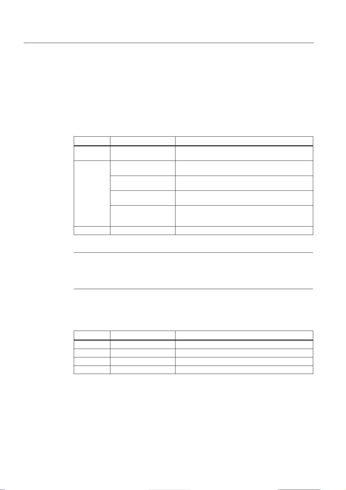
Position of the C-PLUG/KEY-PLUG with rack devices
3.4 C-PLUG / KEY-PLUG
The configuration stored on the C-PLUG/KEY-PLUG is displayed via the user interfaces.
If changes are made to the configuration, the device stores the configuration directly on the
C-PLUG/KEY-PLUG, if this is in the "ACCEPTED" status. The internal memory is neither
read nor written.
Inserting a C-PLUG/KEY-PLUG that does not contain the configuration of a compatible
device type, accidentally removing the C-PLUG/KEY-PLUG or general malfunctions of the CPLUG/KEY-PLUG are signaled by the diagnostics mechanisms of the device (LEDs, Webbased management (WBM), SNMP, Command Line Interface (CLI) and PROFINET
diagnostics).
The user then has the choice of either removing the C-PLUG/KEY-PLUG again or selecting
the option to reformat the C-PLUG/KEY-PLUG.
A C-PLUG/KEY-PLUG may only be removed or inserted when the device is turned off.
On a SCALANCE XR524-8C, the slot is below a cover on
the left-hand side of the housing.
On a SCALANCE XR528-6M and SCALANCE XR552-12M,
the slot is below a cover on the right-hand side of the
housing.
After undoing the screw (screw head Torx T10), you can
remove the cover plate and the slot is accessible.
SCALANCE XR-500
Operating Instructions, 05/2014, A5E03275845-05
25
Description of the device
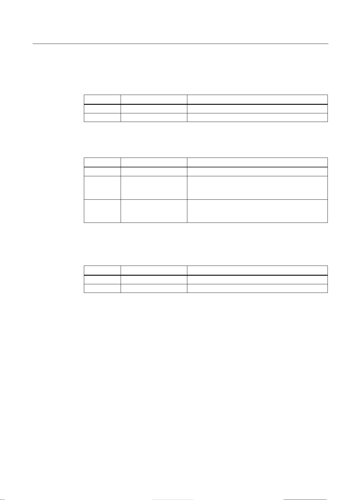
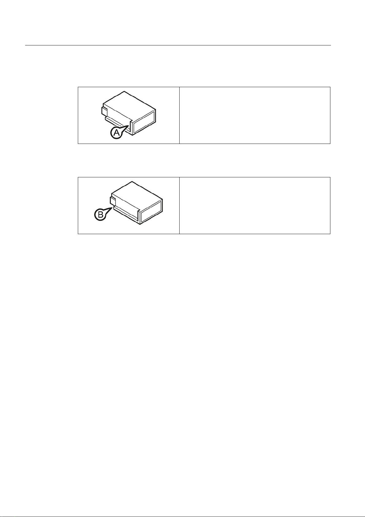
Removing a C-PLUG/KEY-PLUG
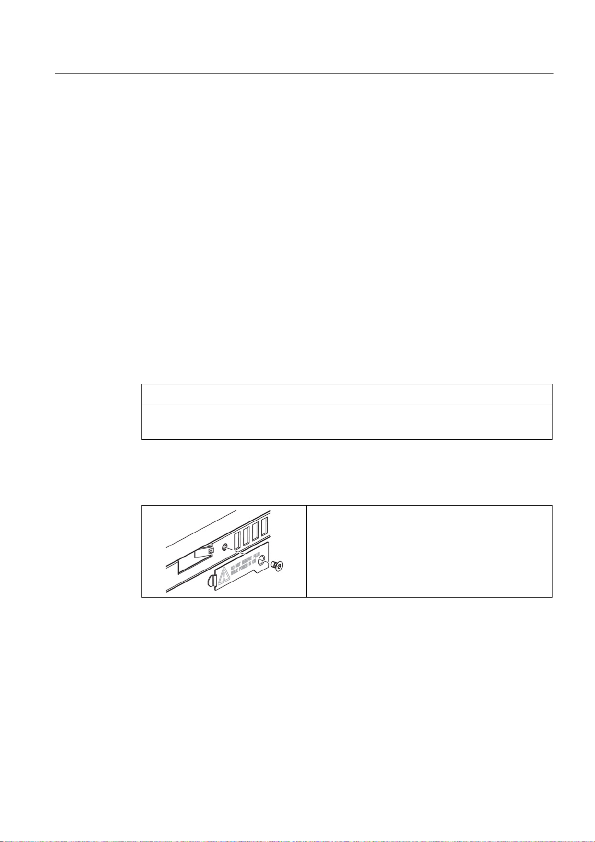
Inserting a C-PLUG/KEY-PLUG
3.4 C-PLUG / KEY-PLUG
1. Turn off the power to the device.
2. Remove the cover.
3. Insert a screwdriver between the front edge of the CPLUG/KEY-PLUG (position A) and the slot and release
the C-PLUG/KEY-PLUG.
4. Remove the C-PLUG/KEY-PLUG and screw the cover
plate firmly in place again.
1. Turn off the power to the device.
2. Remove the cover.
3. The housing of the C-PLUG/KEY-PLUG has a
protruding ridge on the long side (position B). The slot
has a groove at this position. Insert the C-PLUG/KEYPLUG into the slot correctly aligned.
4. Secure the cover plate again with the screws.
SCALANCE XR-500
26 Operating Instructions, 05/2014, A5E03275845-05

Description of the device
3.5
Combo ports
Characteristics
Setting the mode
auto
rj45
sfp
3.5 Combo ports
The following devices have combo ports:
● SCALANCE XR524-8C
Combo port is the name for two communication ports. A combo port has the two following
jacks:
● a fixed RJ-45 port
● an SFP transceiver slot that can be equipped individually
Of these two ports, only one can ever be active. Using the mode, you can decide how the
ports are prioritized.
The port name is the same on both jacks of the combo port, for example "P3C.
For each combo port there is an LED. The LEDs for the combo ports can be identified by a
vertical line and the word "COMBO". The labeling of the combo port LEDs does not differ
from that of the other LEDs, e.g. "P3".
The following modes can be configured for a combo port:
● Mode 1:
The SFP transceiver port has priority. As soon as an SFP transceiver is plugged in, an
existing connection at the fixed RJ-45 port is terminated. If no SFC transceiver is plugged
in, a connection can be established via the fixed RJ-45 port.
● Mode 2:
The fixed RJ-45 port is independent of the SFP transceiver port.
● Mode 3:
The pluggable transceiver port is used independent of the fixed RJ-45 port.
The factory setting for the combo ports is mode 1: auto.
You configure the mode with Web Based Management or the Command Line Interface.
SCALANCE XR-500
Operating Instructions, 05/2014, A5E03275845-05
27

Description of the device
3.5 Combo ports
SCALANCE XR-500
28 Operating Instructions, 05/2014, A5E03275845-05
4
4.1
Safety notices for installation
Safety notices
CAUTION
Use only approved components
NOTICE
Damage to the device due to inadequate cooling
NOTICE
Warming and premature aging of the IE switch due to direct sunlight
When installing the device, keep to the safety notices listed below.
If you use components and accessories that are not approved for SIMATIC NET devices or
their target systems, this may violate the requirements and regulations for safety and
electromagnetic compatibility.
• Use only components that are approved for SIMATIC NET devices.
• Create any supports you require according the dimension drawing.
If the ventilation slits are fully or partly covered, the temperature inside the housing can rise
and exceed the maximum permitted temperature causing damage to the device.
The ventilation slits are located on the side panels of the housing. During installation, select
a mounting position so that the ventilation slits are always free so that the air can circulate.
The clearance to the ventilation slits of the housing must be at least 10 cm.
You will find information about cleaning the air filter in the section "Upkeep and
maintenance".
Close unused module slots of modular devices with dummy covers. Open module slots
impair the air circulation and can damage the device.
Direct sunlight can heat up the device and can lead to premature aging of the IE switch and
its cabling.
Provide suitable shade to protect the IE switch against direct sunlight.
SCALANCE XR-500
Operating Instructions, 05/2014, A5E03275845-05
29
Assembling
Note
During installation and operation, keep to the installation guidelines and safety notices
described in this document and in the
Industrial Ethernet" and "Industrial Ethernet / PROFINET passive network components".
You will find information on the system manuals in the section "
"Further documentation".
Safety notices on use in hazardous areas
General safety notices relating to protection against explosion
WARNING
EXPLOSION HAZARD
SUBSTITUTION OF COMPONENTS MAY IMPAIR SUITABILITY FOR CLASS I, DIVISION
WARNING
Safety notices for use according to ATEX and IECEx
WARNING
4.1 Safety notices for installation
system manuals "Industrial Ethernet / PROFINET
Introduction (Page 5)", in
2 OR ZONE 2.
When used in hazardous environments corresponding to Class I, Division 2 or Class I,
Zone 2, the device must be installed in a cabinet or a suitable enclosure.
If you use the device under ATEX or IECEx conditions you must also keep to the following
safety notices in addition to the general safety notices for protection against explosion:
To comply with EC Directive 94/9 (ATEX95) or the conditions of IECEx, this enclosure must
meet the requirements of at least IP54 in compliance with EN 60529.
SCALANCE XR-500
30 Operating Instructions, 05/2014, A5E03275845-05
 Loading...