

Siemens SCALANCE XR524-8C, SCALANCE XR526-8C, SCALANCE XR528-6M, SCALANCE XR552-12M, SCALANCE XR-500 Operating Instructions Manual

___________________
___________________
___________________
___________________
___________________
___________________
___________________
___________________
___________________
SIMATIC NET
Industrial Ethernet switches
SCALANCE XR-500
Operating Instructions
05/2017
A5E03275845
Introduction
1
Safety notes
2
Description of the device
3
Assembling
4
Connecting
5
Uninstalling
6
Upkeep and maintenance
7
Technical data
8
Dimension drawings
9
Certification
10
-11
Siemens AG
Division Process Industries and Drives
Postfach 48 48
90026 NÜRNBERG
GERMANY
A5E03275845-11
Ⓟ
Copyright © Siemens AG 2011 - 2017.
All rights reserved
Legal information
Warning notice system
DANGER
indicates that death or severe personal injury will result if proper precautions are not taken.
WARNING
indicates that death or severe personal injury may result if proper precautions are not taken.
CAUTION
indicates that minor personal injury can result if proper precautions are not taken.
NOTICE
indicates that property damage can result if proper precautions are not taken.
Qualified Personnel
personnel qualified
Proper use of Siemens products
WARNING
Siemens products may only be used for the applications described in the catalog and in the relevant technical
maintenance are required to ensure that the products operate safely and without any problems. The permissible
ambient conditions must be complied with. The information in the relevant documentation must be observed.
Trademarks
Disclaimer of Liability
This manual contains notices you have to observe in order to ensure your personal safety, as well as to prevent
damage to property. The notices referring to your personal safety are highlighted in the manual by a safety alert
symbol, notices referring only to property damage have no safety alert symbol. These notices shown below are
graded according to the degree of danger.
If more than one degree of danger is present, the warning notice representing the highest degree of danger will
be used. A notice warning of injury to persons with a safety alert symbol may also include a warning relating to
property damage.
The product/system described in this documentation may be operated only by
task in accordance with the relevant documentation, in particular its warning notices and safety instructions.
Qualified personnel are those who, based on their training and experience, are capable of identifying risks and
avoiding potential hazards when working with these products/systems.
Note the following:
documentation. If products and components from other manufacturers are used, these must be recommended
or approved by Siemens. Proper transport, storage, installation, assembly, commissioning, operation and
All names identified by ® are registered trademarks of Siemens AG. The remaining trademarks in this publication
may be trademarks whose use by third parties for their own purposes could violate the rights of the owner.
We have reviewed the contents of this publication to ensure consistency with the hardware and software
described. Since variance cannot be precluded entirely, we cannot guarantee full consistency. However, the
information in this publication is reviewed regularly and any necessary corrections are included in subsequent
editions.
for the specific
05/2017 Subject to change

Table of contents
1 Introduction ............................................................................................................................................. 5
2 Safety notes ............................................................................................................................................ 9
3 Description of the device ....................................................................................................................... 17
4 Assembling ........................................................................................................................................... 37
2.1 Security recommendations ..................................................................................................... 11
3.1 Product overview .................................................................................................................... 17
3.1.1 Permitted ambient temperature .............................................................................................. 19
3.1.2 Accessories ............................................................................................................................. 20
3.1.2.1 Accessories for the SCALANCE XR-500 product line ............................................................ 20
3.1.2.2 Additional accessories for modular devices ........................................................................... 23
3.1.3 Accessories SFP+ cable ......................................................................................................... 24
3.2 SELECT/SET button ............................................................................................................... 25
3.3 LED display ............................................................................................................................. 28
3.3.1 The "RM" LED for the "redundancy manager" function .......................................................... 28
3.3.2 The "SB" LED for the standby function ................................................................................... 28
3.3.3 The "F" LED for the fault status .............................................................................................. 28
3.3.4 "DM1" and "DM2" LEDs for the display mode ........................................................................ 29
3.3.5 "L1" and "L2" LEDs for the power supply ............................................................................... 29
3.3.6 Port P1, P2, ... LEDs for the port status.................................................................................. 31
3.4 C-PLUG / KEY-PLUG ............................................................................................................. 32
3.4.1 Function of the C-PLUG/KEY-PLUG ...................................................................................... 32
3.4.2 Removal and insertion of the C-PLUG/KEY-PLUG ................................................................ 34
3.5 Combo ports ........................................................................................................................... 35
4.1 Safety notices for installation .................................................................................................. 37
4.2 Types of installation ................................................................................................................ 40
4.3 19" rack mounting ................................................................................................................... 40
4.4 Desktop operation with adhesive feet ..................................................................................... 43
4.5 Four-point mounting ................................................................................................................ 44
4.6 Plugging and pulling MM900 media modules ......................................................................... 47
4.7 Inserting and removing pluggable transceivers (SFP/SFP+) ................................................. 50
4.7.1 Notes on inserting/removing pluggable transceivers .............................................................. 50
4.7.2 Inserting a pluggable transceiver (SFP/SFP+) ....................................................................... 51
4.7.3 Removing a pluggable transceiver (SFP/SFP+) ..................................................................... 51
4.8 Mounting power supply units .................................................................................................. 52
4.8.1 19" rack mounting of the PS598-1 power supply unit ............................................................. 52
4.8.2 Mounting the PS598-1 power supply unit on the rear panel of modular device ..................... 53
SCALANCE XR-500
Operating Instructions, 05/2017, A5E03275845-11
3

Table of contents
5 Connecting ........................................................................................................................................... 55
6 Uninstalling ........................................................................................................................................... 73
7 Upkeep and maintenance ..................................................................................................................... 75
8 Technical data ...................................................................................................................................... 83
9 Dimension drawings .............................................................................................................................. 95
10 Certification .......................................................................................................................................... 103
Index ................................................................................................................................................... 111
5.1 Commissioning....................................................................................................................... 55
5.2 24 VDC power supply ............................................................................................................ 58
5.3 100 to 240 VAC power supply ............................................................................................... 60
5.3.1 Power supply of the SCALANCE XR524-8C and SCALANCE XR526-8C ........................... 60
5.3.2 Power supply using the PS598-1 power supply unit.............................................................. 61
5.3.2.1 Connectors of the PS598-1 power supply unit ...................................................................... 61
5.3.2.2 LED display of the PS598-1 power supply unit ...................................................................... 65
5.4 Signaling contact .................................................................................................................... 65
5.5 Serial interface ....................................................................................................................... 67
5.6 Out-of-band interface ............................................................................................................. 68
5.7 Block architecture of the XR552-12M .................................................................................... 70
5.8 Functional ground .................................................................................................................. 70
7.1 Changing the fan unit ............................................................................................................. 75
7.2 Changing the filter pad ........................................................................................................... 78
7.3 Downloading new firmware using TFTP without WBM and CLI ............................................ 79
7.4 Restoring the factory settings ................................................................................................ 80
8.1 Technical specifications of the SCALANCE XR524-8C......................................................... 83
8.2 Technical specifications of the SCALANCE XR526-8C......................................................... 86
8.3 Technical specifications of the SCALANCE XR528-6M ........................................................ 89
8.4 Technical specifications of the SCALANCE XR552-12M ...................................................... 91
8.5 Switching properties ............................................................................................................... 93
9.1 SCALANCE XR524-8C and SCALANCE XR526-8C ............................................................ 95
9.2 SCALANCE XR528-6M ......................................................................................................... 96
9.3 SCALANCE XR552-12M ....................................................................................................... 97
9.4 Mounting brackets for use on ships ....................................................................................... 97
10.1 FDA and IEC marks ............................................................................................................. 108
10.2 Mechanical stability (in operation)........................................................................................ 108
SCALANCE XR-500
4 Operating Instructions, 05/2017, A5E03275845-11

1
Purpose of the Operating Instructions
Validity of the Operating Instructions
Designations used
Classification
Description
Terms used
SCALANCE XR-500 is used.
SCALANCE XR552-12M
added to it in brackets.
VDC)
Documentation on configuration
These operating instructions support you when installing and connecting up devices of the
SCALANCE XR-500 product line.
The configuration and the integration of the device in a network are not described in these
operating instructions.
These operating instructions apply to the following devices:
● SCALANCE XR524-8C
● SCALANCE XR526-8C
● SCALANCE XR528-6M
● SCALANCE XR552-12M
Product line If information applies to all product groups within the product line, the term
Device If information relates to a specific device, the device name is used. SCALANCE XR524-8C
Variant For a variant of the device, the device name has the appropriate variant
SCALANCE XR-500
SCALANCE XR526-8C
SCALANCE XR528-6M
SCALANCE XR524-8C (2 x 24
You will find detailed information on configuring the devices in the following configuration
manuals:
● SCALANCE XM-400/XR-500 Web Based Management
SCALANCE XR-500
Operating Instructions, 05/2017, A5E03275845-11
● SCALANCE XM-400/XR-500 Command Line Interface
5

Introduction
Further documentation
SIMATIC NET manuals
You will find the configuration manuals here:
● On the data medium that ships with some products:
– Product CD / product DVD
– SIMATIC NET Manual Collection
● On the Internet pages of Siemens Industry Online Support.
(http://support.automation.siemens.com/WW/view/en/48803858/133300)
In the system manuals "Industrial Ethernet / PROFINET Industrial Ethernet" and "Industrial
Ethernet / PROFINET passive network components", you will find information on other
SIMATIC NET products that you can operate along with the devices of this product line in an
Industrial Ethernet network.
There, you will find among other things optical performance data of the communications
partner that you require for the installation.
You will find the system manuals here:
● On the data medium that ships with some products:
– Product CD / product DVD
– SIMATIC NET Manual Collection
● On the Internet pages of Siemens Industry Online Support under the following entry IDs:
– 27069465 (http://support.automation.siemens.com/WW/view/en/27069465)
– 84922825 (http://support.automation.siemens.com/WW/view/en/84922825)
You will find the SIMATIC NET manuals here:
● On the data medium that ships with some products:
– Product CD / product DVD
– SIMATIC NET Manual Collection
● On the Internet pages of Siemens Industry Online Support
(http://support.automation.siemens.com/WW/view/en/10805878/130000).
Industrial Ethernet / PROFINET Industrial Ethernet System Manual
Industrial Ethernet / PROFINET - Passive network components System Manual
SCALANCE XR-500
6 Operating Instructions, 05/2017, A5E03275845-11

Introduction
SIMATIC NET glossary
Catalogs
Security information
Explanations of many of the specialist terms used in this documentation can be found in the
SIMATIC NET glossary.
You will find the SIMATIC NET glossary here:
● SIMATIC NET Manual Collection or product DVD
The DVD ships with certain SIMATIC NET products.
● On the Internet under the following address:
50305045 (http://support.automation.siemens.com/WW/view/en/50305045)
You will find the article numbers for the Siemens products of relevance here in the following
catalogs:
● SIMATIC NET Industrial Communication / Industrial Identification, catalog IK PI
● SIMATIC Products for Totally Integrated Automation and Micro Automation, catalog
ST 70
● Industry Mall - catalog and ordering system for automation and drive technology, Online
You can request the catalogs and additional information from your Siemens representative.
Siemens provides products and solutions with industrial security functions that support the
secure operation of plants, systems, machines and networks.
In order to protect plants, systems, machines and networks against cyber threats, it is
necessary to implement – and continuously maintain – a holistic, state-of-the-art industrial
security concept. Siemens’ products and solutions only form one element of such a concept.
Customer is responsible to prevent unauthorized access to its plants, systems, machines
and networks. Systems, machines and components should only be connected to the
enterprise network or the internet if and to the extent necessary and with appropriate security
measures (e.g. use of firewalls and network segmentation) in place.
Additionally, Siemens’ guidance on appropriate security measures should be taken into
account. For more information about industrial security, please visit
http://www.siemens.com/industrialsecurity (http://www.siemens.com/industrialsecurity)
Siemens’ products and solutions undergo continuous development to make them more
secure. Siemens strongly recommends to apply product updates as soon as available and to
always use the latest product versions. Use of product versions that are no longer supported,
and failure to apply latest updates may increase customer’s exposure to cyber threats.
catalog
To stay informed about product updates, subscribe to the Siemens Industrial Security RSS
Feed under
https://support.industry.siemens.com/cs/ww/en/ps/15247/pm
(https://support.industry.siemens.com/cs/ww/en/ps/15247/pm).
SCALANCE XR-500
Operating Instructions, 05/2017, A5E03275845-11
7
Introduction
Unpacking and checking
WARNING
Do not use any parts that show evidence of damage
If you use damaged parts, there is no guarantee that the device will function according to
the specification.
If you use damaged parts, this can lead to the following problems:
• Injury to persons
• Loss of the approvals
• Violation of the EMC regulations
• Damage to the device and other components
Use only undamaged parts.
1. Make sure that the package is complete.
2. Check all the parts for transport damage.
SCALANCE XR-500
8 Operating Instructions, 05/2017, A5E03275845-11
2
Read the safety notices
General notices
WARNING
Restricted use of the device
WARNING
Maximum ambient temperature
WARNING
Suitable installation location
Note the following safety notices. These relate to the entire working life of the device.
You should also read the safety notices relating to handling in the individual sections,
particularly in the sections "Installation" and "Connecting up".
Devices of the SCALANCE XR-500 product line must not be put into operation in nuclear
power plants or other nuclear facilities.
Note that some factors influence the maximum permitted ambient temperature, refer to the
sections "Permitted ambient temperature (Page 19)", "Safety notices for installation
(Page 37)", "Desktop operation with adhesive feet (Page 43)" and "Technical data
(Page 83)".
The installation location of a device of the SCALANCE XR-500 product line must be
selected so that only qualified service personnel or trained users have access to it.
Operation of a device of the SCALANCE XR-500 product line is permitted only when these
requirements are met.
SCALANCE XR-500
Operating Instructions, 05/2017, A5E03275845-11
9
Safety notes
NOTICE
Suitable fusing for the power supply cables
Safety notices on use in hazardous areas
General safety notices relating to protection against explosion
WARNING
Opening the device
Safety notices for use according to ATEX and IECEx
WARNING
EXPLOSION HAZARD
The current on the terminal may not exceed 25 A. Use a fuse, that protects against currents
> 25 A. The fuse must meet the following requirements:
In areas according to NEC or CEC:
• Suitable for DC (min. 60 V / 25 A)
• Breaking current at least 10 kA
• Approval according to ANSI/UL 248-1
• Suitable for the protection of DC power supply circuits
In other areas:
• Suitable for DC (min. 60 V / 25 A)
• Breaking current at least 10 kA
• Approval in compliance with IEC 60127-1 / EN 601127-1
• Breaking characteristics: B or C for circuit breakers and fuses
• Suitable for the protection of DC power supply circuits
Do not open when energized. Note that this does not apply to opening the service panel in
the housing.
If you use the device under ATEX or IECEx conditions you must also keep to the following
safety notices in addition to the general safety notices for protection against explosion:
Do not press the SELECT/SET button when there is an explosive atmosphere.
SCALANCE XR-500
10 Operating Instructions, 05/2017, A5E03275845-11

Safety notes
Safety notices when using the device according to Hazardous Locations (HazLoc)
2.1
Security recommendations
NOTICE
Information security
General
Physical access
2.1 Security recommendations
If you use the device under HazLoc conditions you must also keep to the following safety
notices in addition to the general safety notices for protection against explosion:
This equipment is suitable for use in Class I, Division 2, Groups A, B, C and D or nonhazardous locations only.
This equipment is suitable for use in Class I, Zone 2, Group IIC or non-hazardous locations
only.
Connect to the device and change the standard password for the user set in the factory
"admin" and "" before you operate the device.
To prevent unauthorized access, note the following security recommendations.
● You should make regular checks to make sure that the device meets these
recommendations and/or other security guidelines.
● Evaluate your plant as a whole in terms of security. Use a cell protection concept with
suitable products (http://www.industry.siemens.com/topics/global/en/industrial-
security/network-security/Pages/Default.aspx).
● When the internal and external network are disconnected, an attacker cannot access
internal data from the outside. Therefore operate the device only within a protected
network area.
● For communication via non-secure networks use additional devices with VPN functionality
to encrypt and authenticate the communication.
● Terminate management connections correctly (WBM. Telnet, SSH etc.).
● Restrict physical access to the device to qualified personnel.
– The memory card or the PLUG (C-PLUG, KEY-PLUG) contains sensitive data such as
certificates, keys etc. that can be read out and modified.
SCALANCE XR-500
Operating Instructions, 05/2017, A5E03275845-11
– Using the button, you can reset the device to the factory defaults.
● If the device is publicly accessible, disable the functions of the button using the software.
● Lock unused physical ports on the device. Unused ports can be used to gain forbidden
access to the plant.
11

Safety notes
Software (security functions)
Passwords
Certificates and keys
2.1 Security recommendations
● Keep the firmware up to date. Check regularly for security updates for the device. You will
find information on this on the Internet pages Industrial Security
(http://www.siemens.com/industrialsecurity).
● Inform yourself regularly about security recommendations by Siemens ProductCERT
(http://www.siemens.com/cert/en/cert-security-advisories.htm).
● Only activate protocols that you require to use the device.
● Restrict access to the management of the device with rules in an access control list
(ACL).
● The option of VLAN structuring provides protection against DoS attacks and unauthorized
access. Check whether this is practical or useful in your environment.
● Use a central logging server to log changes and accesses. Operate your logging server
within the protected network area and check the logging information regularly.
● Define rules for the assignment of passwords.
● Regularly change your passwords to increase security.
● Use passwords with a high password strength.
● Make sure that all passwords are protected and inaccessible to unauthorized persons.
● Do not use the same password for different users and systems.
● On the device there is a preset SSL certificate with key. Replace this certificate with a
● Use a certification authority including key revocation and management to sign certificates.
● Make sure that user-defined private keys are protected and inaccessible to unauthorized
● It is recommended that you use password-protected certificates in the PKCS #12 format
● Verify certificates and fingerprints on the server and client to prevent "man in the middle"
● It is recommended that you use certificates with a key length of at least 2048 bits.
● Change certificates and keys immediately, if there is a suspicion of compromise.
self-made certificate with key. We recommend that you use a certificate signed either by
a reliable external or by an internal certification authority.
persons.
attacks.
SCALANCE XR-500
12 Operating Instructions, 05/2017, A5E03275845-11

Safety notes
Secure/non-secure protocols and services
2.1 Security recommendations
● Avoid or disable non-secure protocols and services, for example HTTP, Telnet and TFTP.
For historical reasons, these protocols are available, however not intended for secure
applications. Use non-secure protocols on the device with caution.
● Check whether use of the following protocols and services is necessary:
– Non authenticated and unencrypted ports
– MRP, HRP
– IGMP snooping
– LLDP
– Syslog
– RADIUS
– DHCP Options 66/67
– TFTP
– GMRP and GVRP
● The following protocols provide secure alternatives:
– HTTP → HTTPS
– Telnet → SSH
– SNMPv1/v2c → SNMPv3
Check whether use of SNMPv1/v2c. is necessary. SNMPv1/v2c is classified as nonsecure. Use the option of preventing write access. The device provides you with
suitable setting options.
If SNMP is enabled, change the community names. If no unrestricted access is
necessary, restrict access with SNMP.
Use the authentication and encryption mechanisms of SNMPv3.
● Use secure protocols when access to the device is not prevented by physical protection
measures.
● If you require non-secure protocols and services, operate the device only within a
protected network area.
● Restrict the services and protocols available to the outside to a minimum.
● For the DCP function, enable the "Read Only" mode after commissioning.
● If you use RADIUS for management access to the device, activate secure protocols and
services.
SCALANCE XR-500
Operating Instructions, 05/2017, A5E03275845-11
13

Safety notes
Interfaces security
Available protocols
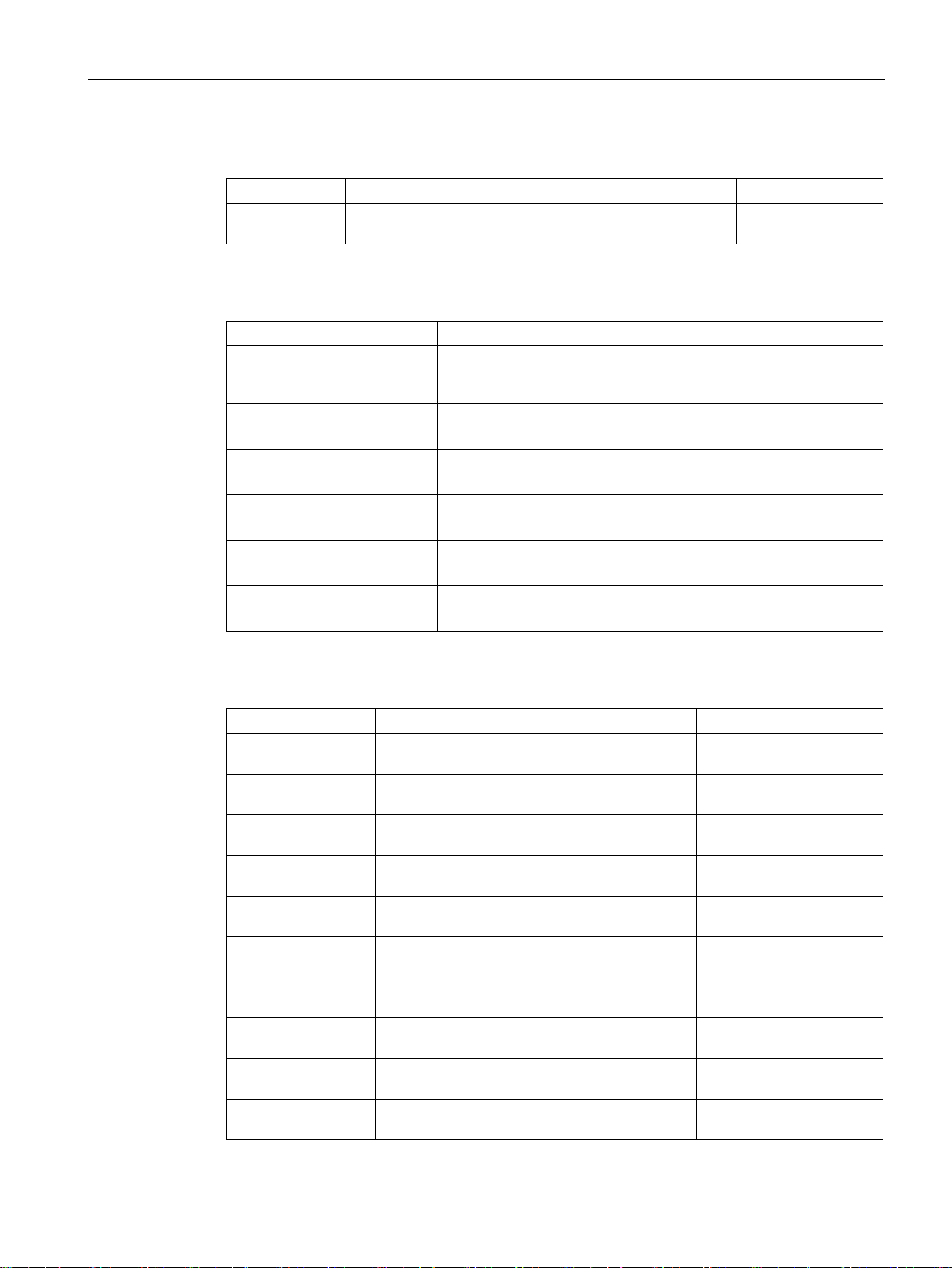
Protocol
Port
Port status
Factory setting
Authentication
Encryption
Protocol
Port number
Port status
Default status of the
port
Authentication
Encryption
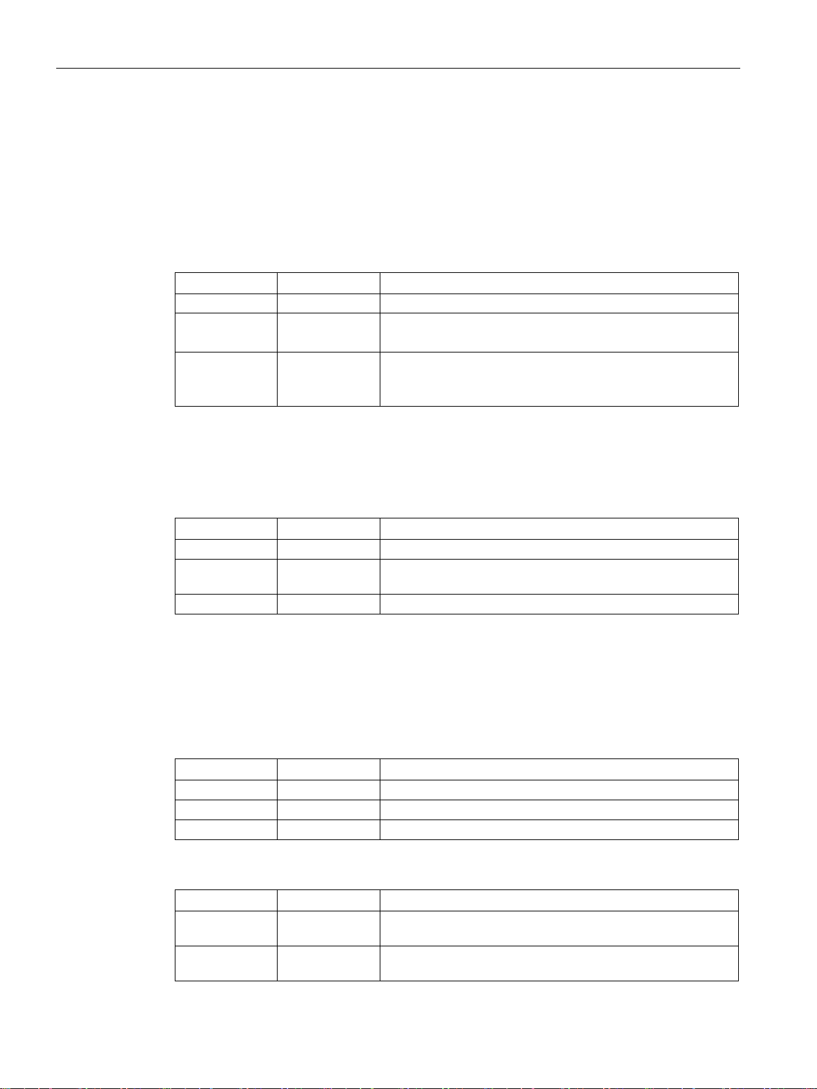
TELNET
ured)
SSH
HTTP
ured)
HTTPS
ured)
2.1 Security recommendations
● Disable unused interfaces.
● Use IEEE 802.1X for interface authentication.
● Use the function "Locked Ports" to block interfaces for unknown nodes.
● Use the configuration options of the interfaces, e.g. the "Edge Type".
● Configure the receive ports so that they discard all untagged frames ("Tagged Frames
Only").
The following list provides you with an overview of the open protocol ports.
The table includes the following columns:
●
●
●
– Open
The port is always open and cannot be closed.
– Open (when configured)
The port is open if it has been configured.
●
– Open
The factory setting of the port is "Open".
– Closed
The factory setting of the port is "Closed".
●
Specifies whether or not the protocol is authenticated.
●
Specifies whether or not the transfer is encrypted.
TCP/23 Open (when config-
Open Yes No
TCP/22 Open (when config-
TCP/80 Open (when config-
TCP/443 Open (when config-
SCALANCE XR-500
14 Operating Instructions, 05/2017, A5E03275845-11
Open Yes Yes
ured)
Open Yes No
Open Yes Yes

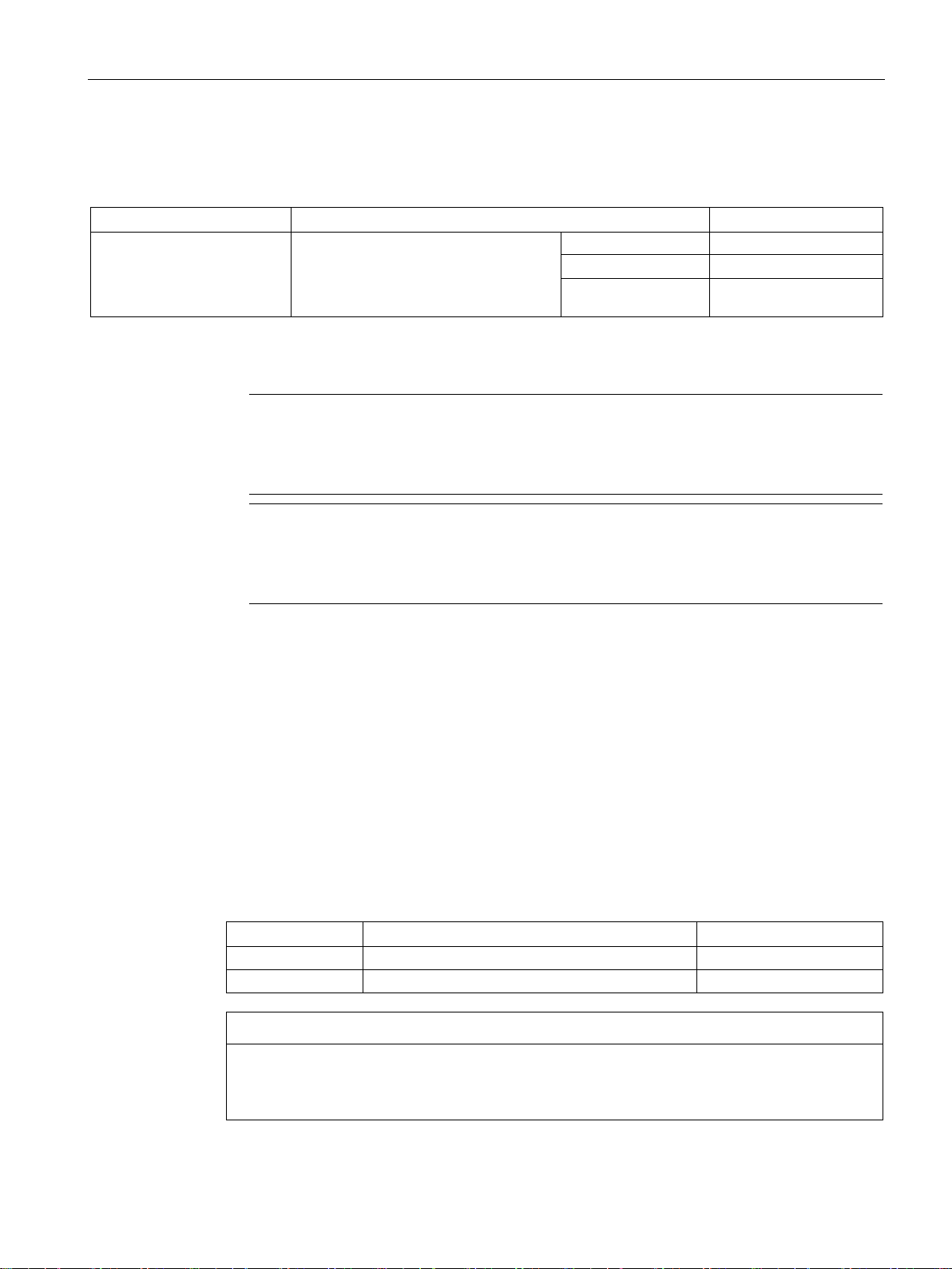
Safety notes
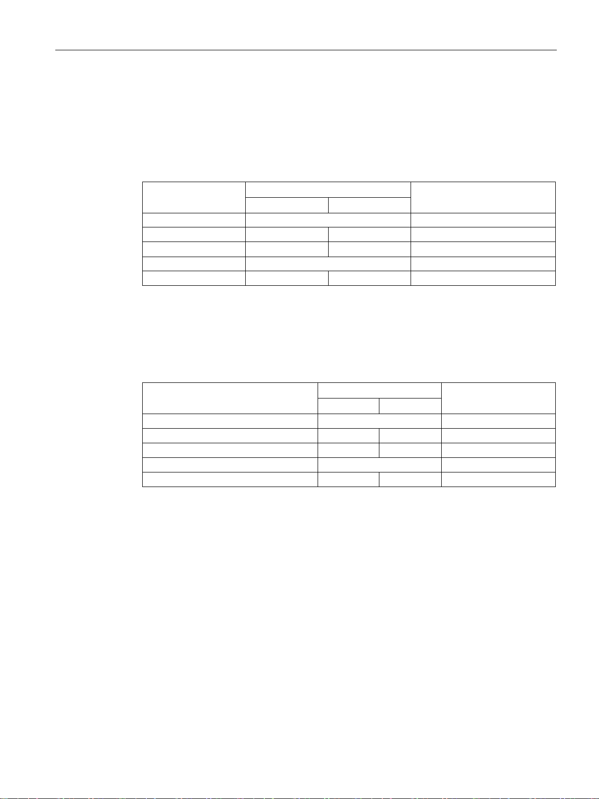
Protocol
Port number
Port status
Default status of the
port
Authentication
Encryption
SNMP
ured)
configured)
SNTP
NTP
PROFINET
49155
EtherNet/IP
818
DHCP
ured)
Syslog
ured)
RADIUS
13
ured)
TFTP
ured)
RIP
ured)
2.1 Security recommendations
UDP/161 Open (when config-
UDP/34964,
TCP/44818,
UDP/67,68 Open (when config-
UDP/514 Open (when config-
UDP/1812,18
UDP/69 Open (when config-
UDP/520 Open (when config-
UDP/123 Open (when config-
ured)
Open Open No No
UDP/49154,
Open (when config-
UDP/2222,44
ured)
Open (when config-
Open Yes Yes (when
Closed No No
Open No No
Closed No No
Open No No
Closed No No
Closed No No
Closed No No
SCALANCE XR-500
Operating Instructions, 05/2017, A5E03275845-11
15

Safety notes
2.1 Security recommendations
SCALANCE XR-500
16 Operating Instructions, 05/2017, A5E03275845-11
3
3.1
Product overview
Article numbers
Device
Properties
Article number
Firmware
version
front, layer 3 with KEY-PLUG
front, layer 3 integrated
on the rear, layer 3 with KEY-PLUG
on the rear, layer 3 integrated
on the rear, layer 3 with KEY-PLUG
power supply on the front, layer 3 with KEY-PLUG *)
supply on the front, layer 3 integrated *)
power supply on the rear, layer 3 with KEY-PLUG
power supply on the rear, layer 3 integrated
power supply on the rear, layer 3 with KEY-PLUG
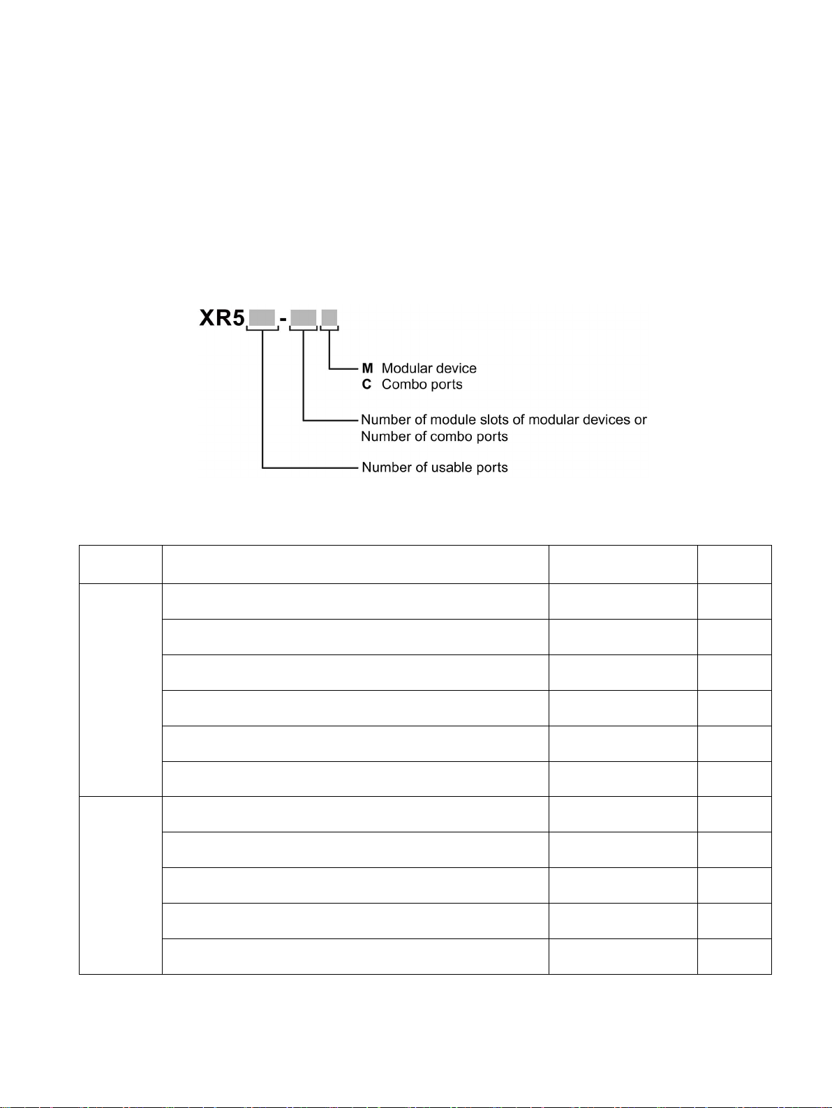
The type designation of a SCALANCE XR-500 IE switch is made up of several parts that
have the following meaning:
XR524-8C 1 height unit, 2 x 24 VDC, connector for the power supply on the
1 height unit, 2 x 24 VDC, connector for the power supply on the
1 height unit, 1 x 100 to 240 VAC, connector for the power supply
1 height unit, 1 x 100 to 240 VAC, connector for the power supply
1 height unit, 2 x 100 to 240 VAC, connector for the power supply
1 height unit, 2 x 100 to 240 VAC, connector for the power supply
on the rear, layer 3 integrated
XR526-8C This 1 height unit, 2 SFP+ slots, 2 x 24 VDC, connector for the
1 height unit, 2 SFP+ slots, 2 x 24 VDC, connector for the power
6GK5 524-8GS00-2AR2 as of V4.1
6GK5 524-8GR00-2AR2 as of V4.1
6GK5 524-8GS00-3AR2 as of V4.2
6GK5 524-8GR00-3AR2 as of V4.2
6GK5 524-8GS00-4AR2 as of V4.2
6GK5 524-8GR00-4AR2 as of V4.2
6GK5 526-8GS00-2AR2 V4.3
6GK5 526-8GR00-2AR2 V4.3
1 height unit, 2 SFP+ slots, 1 x 100 to 240 VAC, connector for the
1 height unit, 2 SFP+ slots, 1 x 100 to 240 VAC, connector for the
1 height unit, 2 SFP+ slots, 2 x 100 to 240 VAC, connector for the
SCALANCE XR-500
Operating Instructions, 05/2017, A5E03275845-11
6GK5 526-8GS00-3AR2 V4.3
6GK5 526-8GR00-3AR2 V4.3
6GK5 526-8GS00-4AR2 V4.3
17
Description of the device
Device
Properties
Article number
Firmware
version
power supply on the rear, layer 3 integrated
2 height units, 4 SFP+ slots, 6 modules, layer 3 with KEY-PLUG
6GK5 528-0AA00-2AR2
as of V1.0
2 height units, 4 SFP+ slots, 6 modules, cable outlet at rear, layer 3
with KEY-PLUG
2 height units, 4 SFP+ slots, 6 modules, layer 3 integrated
6GK5 528-0AR00-2AR2
as of V1.0
2 height units, 4 SFP+ slots, 6 modules, cable outlet at rear, layer 3
integrated
3 height units, 4 SFP+ slots, 12 modules, layer 3 with KEY-PLUG
6GK5 552-0AA00-2AR2
as of V1.0
3 with KEY-PLUG
3 height units, 4 SFP+ slots, 12 modules, layer 3 integrated
6GK5 552-0AR00-2AR2
as of V1.0
3 integrated
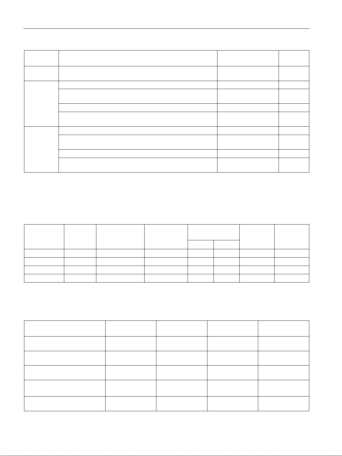
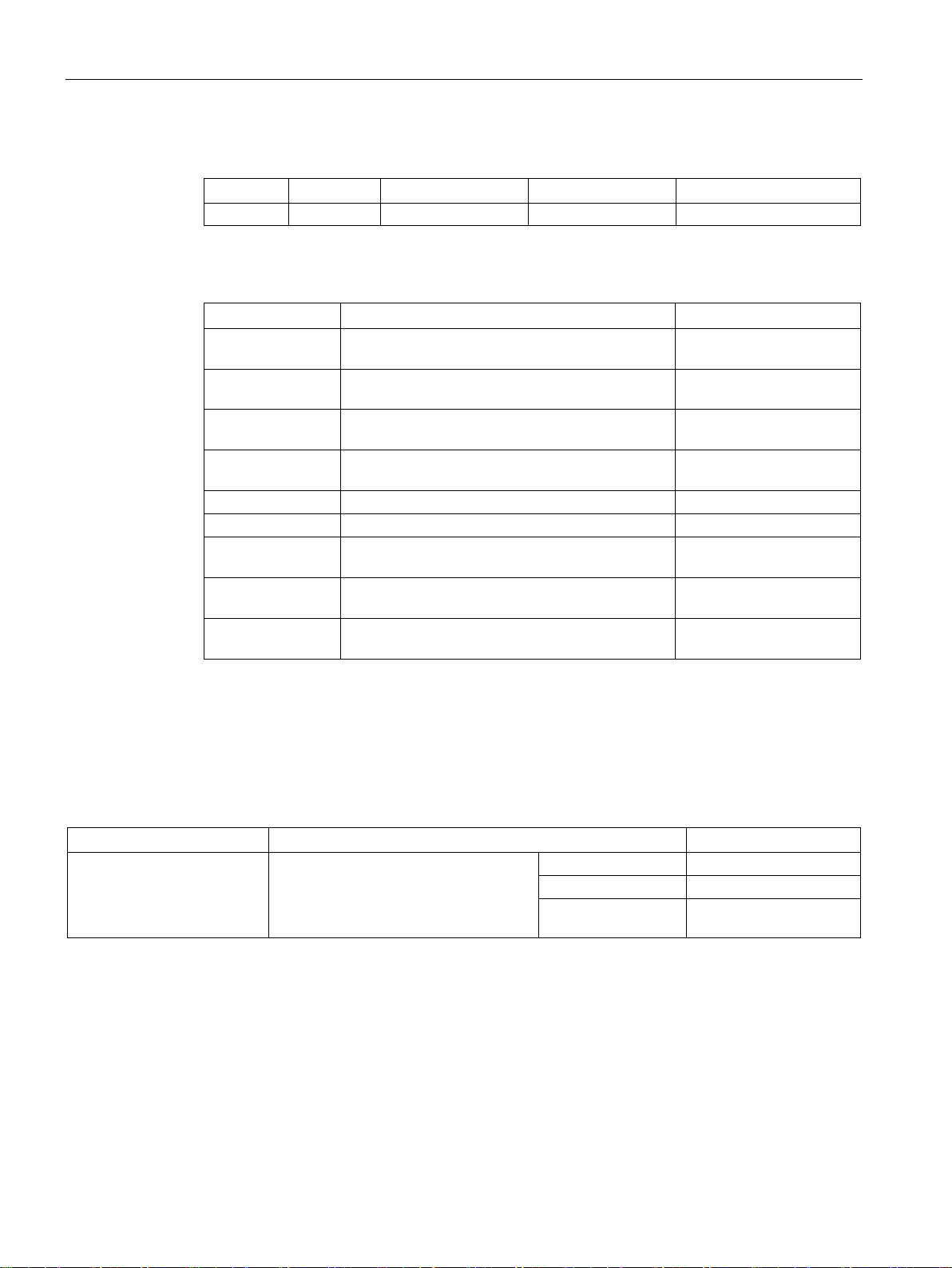
Interfaces
Device
Total usable ports
Number of slots for
media modules
Modular ports
using module
slots
Pluggable transceiver slots
Electrical
connectors
Combo ports
SFP
SFP+
XR524-8C
24 - - 8 -
24
8
XR526-8C
26 - - 8 2
24 8 XR528-6M
28 6 24 - 4 - -
XR552-12M
52
12
48 - 4 - -
Components of the product
SCALANCE
XR524-8C
SCALANCE
XR526-8C
SCALANCE
XR528-6M
SCALANCE
XR552-12M
um C-PLUG
and software
tion
Drive: Torx
Drive: Torx
Drive: Torx
Drive: Torx
ation
3.1 Product overview
XR528-6M
XR552-12M
1 height unit, 2 SFP+ slots, 2 x 100 to 240 VAC, connector for the
3 height units, 4 SFP+ slots, 12 modules, cable outlet at rear, layer
3 height units, 4 SFP+ slots, 12 modules, cable outlet at rear, layer
6GK5 526-8GR00-4AR2 V4.3
6GK5 528-0AA00-2HR2 as of V1.0
6GK5 528-0AR00-2HR2 as of V1.0
6GK5 552-0AA00-2HR2 as of V1.0
6GK5 552-0AR00-2HR2 as of V1.0
*) With the SCALANCE XR526-8C (2 x 24 VDC) if you use SFP/SFP+ pluggable transceivers
in the SFP+ slots, the maximum ambient temperature is reduced to 60 °C, see section
"Permitted ambient temperature (Page 19)".
The following components ship with a SCALANCE XR-500:
Device with exchangeable medi-
Product DVD with documentation
2 brackets for 19" rack installa-
8 screws for mounting the fixing
brackets for 19" rack installation
4 adhesive feet for desktop oper-
SCALANCE XR-500
18 Operating Instructions, 05/2017, A5E03275845-11
● ● ● ●
● ● ● ●
● ● ● ●
M3 x 5 countersunk,
● ● ● ●
M3 x 5 countersunk,
M3 x 6 countersunk,
M3 x 6 countersunk,
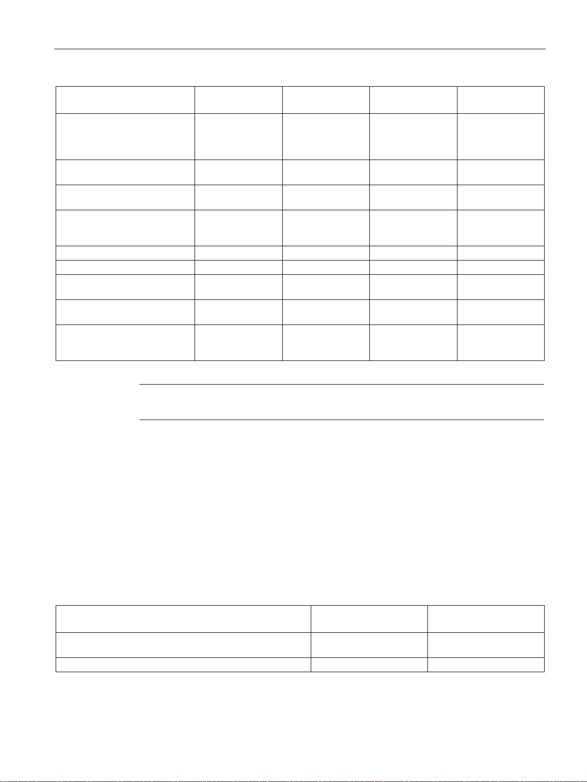
Description of the device
SCALANCE
XR524-8C
SCALANCE
XR526-8C
SCALANCE
XR528-6M
SCALANCE
XR552-12M
Torx)
naling contact
pin D-sub female connector
Fan unit
- - FAN597-2
FAN597-1
Filter frame with filter pad
- - ●
●
SFP/SFP+
of the media module slots
ules in use
Note
When the modules shi
3.1.1
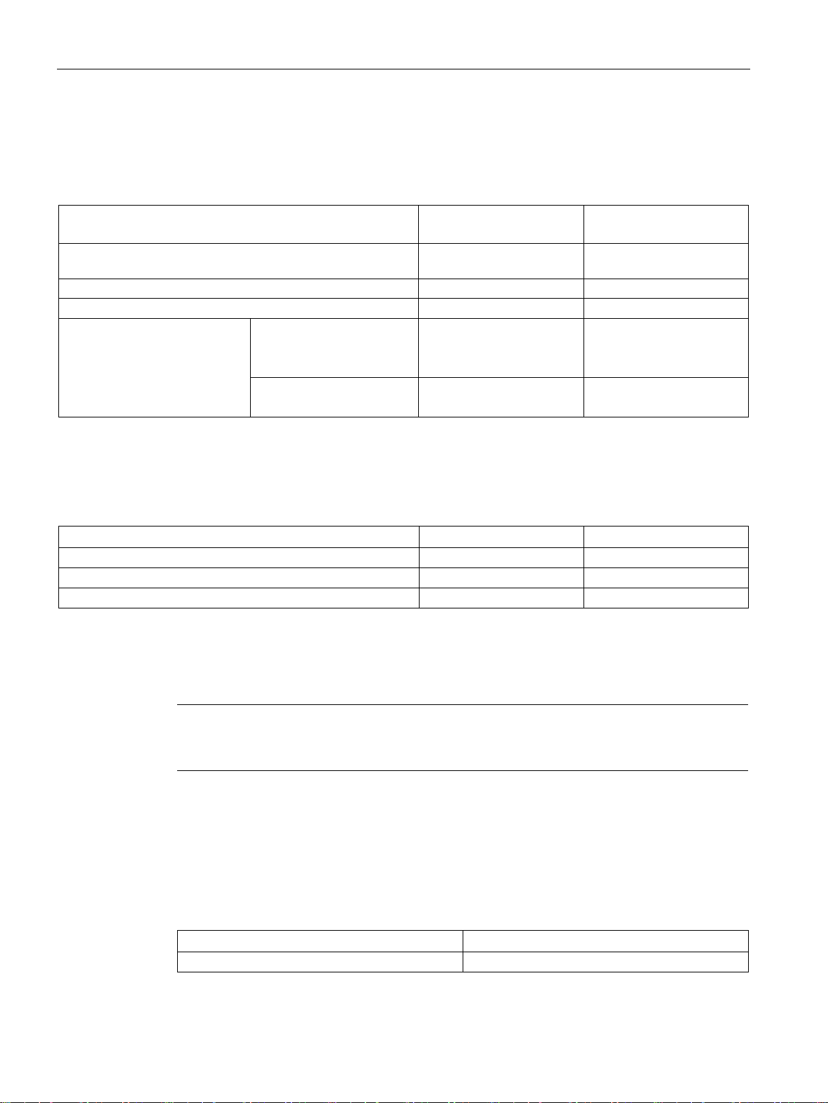
Permitted ambient temperature
SCALANCE XR524-8C
SCALANCE XR524-8C
(24 VDC)
SCALANCE XR524-8C
(240 VAC)
ELH200
With SFP transceivers
-40 ℃ to +60 °C
-25 ℃ to +60 °C
3.1 Product overview
2 mounting plates and 24 screws
for mounting the power supply
units (M3 x 6 countersunk, drive:
4-pin terminal block for the 24
VDC power supply
2-pin terminal block for the sig-
Connecting cable for the serial
interface with RJ-11 plug and 9-
Covers for the interfaces of the
Dummy covers for the interfaces
Labels for the slot numbers to
identify the MM900 media mod-
- - ● ●
With variants with
24 VDC
● ● ● ●
● ● ● ●
8 10 4 4
- - 6 12
- - ● ●
With variants with
24 VDC
● ●
p, the media module slots are fitted with dummy covers.
The maximum permitted ambient temperature of a device of the product line SCALANCE XR
-500 depends on the components used. Note the information with the individual components
in the section "Accessories (Page 20)" and the Technical specifications (Page 83).
For SCALANCE XR524-8C (24 VDC), the ambient temperature must not exceed 70 °C.
For SCALANCE XR524-8C (240 VAC), the ambient temperature must not exceed 60 ℃.
Without pluggable transceiver of the types LH, LH+, ELH or
-40 ℃ to +70 °C -25 ℃ to +60 °C
SCALANCE XR-500
Operating Instructions, 05/2017, A5E03275845-11
19
Description of the device
SCALANCE XR526-8C
SCALANCE XR526-8C
(24 VDC)
SCALANCE XR526-8C
(240 VAC)
ELH200
With SFP transceivers (in SFP+ slots)
0 °C to +60 °C
0 °C to +55 °C
6GK5 993-1AV00-8AA0
6GK5 993-1AU10-8AA0
SCALANCE XR528-6M and SCALANCE XR552-12M
SCALANCE XR528-6M
SCALANCE XR552-12M
Without filter pad and without SFP+ transceiver of the type LH
0 °C to +60 °C
0 °C to +60 °C
With filter pad and without SFP+ transceiver of the type LH
0 °C to +55 °C
0 °C to +55 °C
with filter pad and with SFP+ transceiver of the type LH
0 °C to +50 °C
0 °C to +50 °C
3.1.2
Accessories
Note
You will find detailed information on these products in the operating instructions on the
product DVD.
3.1.2.1
Accessories for the SCALANCE XR-500 product line
KEY-PLUG
Type
Article number
KEY-PLUG XR-500
6GK5 905-0PA00
3.1 Product overview
For SCALANCE XR526-8C (24 VDC), the ambient temperature must not exceed 70 °C.
For SCALANCE XR526-8C (240 VAC), the ambient temperature must not exceed 60 ℃.
Without pluggable transceiver of the types LH, LH+, ELH or
With SFP transceivers (in SFP slots) 0 °C to +60 °C 0 °C to +60 °C
With SFP+ transceivers (in
SFP+ slots)
6GK5 993-1AT00-8AA0
6GK5 993-1AU00-8AA0
6GK5 993-1AT10-8AA0
0 °C to +70 °C 0 °C to +60 °C
0 °C to +50 °C 0 °C to +50 °C
0 °C to +60 °C 0 °C to +55 °C
For SCALANCE XR528-6M and SCALANCE XR552-12M, the ambient temperature must not
exceed 60 °C.
The following accessories are available for the SCALANCE XR-500 product line:
SCALANCE XR-500
20 Operating Instructions, 05/2017, A5E03275845-11
Description of the device
C-PLUG
Component
Description
Article number
figuration data, 32 MB
Power cable
Type
Description
Article number
100 to 240 VAC, straight, 3 m
100 to 240 VAC, straight, 3 m
100 to 240 VAC, straight, 3 m
100 to 240 VAC, straight, 3 m
100 to 240 VAC, straight, 3 m
SFP transceiver
Type
Properties
Article number
(multimode), up to max. 5 km
cable (multimode), up to max. 5 km, varnished
(single mode) up to max. 26 km
(single mode) up to max. 70 km
(single mode) up to max. 200 km
cable (multimode), up to max. 750 m
cable (multimode), up to max. 2 km
cable (single mode) up to max. 10 km
cable (single mode) up to max. 10 km, varnished
3.1 Product overview
C-PLUG Configuration plug, exchangeable storage medium for con-
Power cable
100 to 240 VAC, straight, 3 m
Power cable
Power cable
Power cable
Power cable
Power cable
For Germany, France, Spain, Netherlands, Belgium, Sweden, Austria, Finland
For Great Britain 6ES7 900-0BA00-0XA0
For Switzerland 6ES7 900-0CA00-0XA0
For America 6ES7 900-0DA00-0XA0
For Italy 6ES7 900-0EA00-0XA0
For China 6ES7 900-0FA00-0XA0
6GK1 900-0AB00
6ES7 900-0AA00-0XA0
SFP991-1 * 1 x 100 Mbps, LC port optical for glass FO cable
SFP991-1 (C) * 1 x 100 Mbps, SC port optical, for glass FO
SFP991-1LD * 1 x 100 Mbps LC port optical for glass FO cable
SFP991-1LD (C) * 1 x 100 Mbps LC port optical for glass FO cable
(single mode) up to max. 26 km, varnished
SFP991-1LH+ * 1 x 100 Mbps LC port optical for glass FO cable
SFP991-1ELH200 * 1 x 100 Mbps LC port optical for glass FO cable
SFP992-1 1 x 1000 Mbps, LC port optical for glass FO
SFP992-1+ 1 x 1000 Mbps, LC port optical for glass FO
SFP992-1LD 1 x 1000 Mbps LC port optical for glass FO
SFP992-1LD (C) 1 x 1000 Mbps LC port optical for glass FO
6GK5 991-1AD00-8AA0
6GK5 991-1AD00-8FA0
6GK5 991-1AF00-8AA0
6GK5 991-1AF00-8FA0
6GK5 991-1AE00-8AA0
6GK5 991-1AE30-8AA0
6GK5 992-1AL00-8AA0
6GK5 992-1AG00-8AA0
6GK5 992-1AM00-8AA0
6GK5 992-1AM00-8FA0
SCALANCE XR-500
Operating Instructions, 05/2017, A5E03275845-11
21

Description of the device
Type
Properties
Article number
cable (single mode) up to max. 40 km
cable (single mode) up to max. 120 km
* Cannot be operated in SFP+ slots.
Pluggable transceivers with the supplement (C) in the type name have varnished printed circuit boards
(conformal coating).
Note
Restriction for pluggable transceivers for SCALANCE XR524-8C (2 x 24 VDC) and
SCALANCE XR526-8C (2 x DC 24 V)
If you use pluggable transceivers of the types LH, LH+, ELH or ELH200 wit
XR524
temperature is reduced to 60
For further information on the ambient temperature, refer to sections “
temperature
Note
No far-end fault detection for an SFP transceiver in SFP+ slots with SCALANCE XR528 and
SCALANCE XR552
If you use an SFP transceiver in
interface. This can impair the functionality of link
SFP+ transceiver
Type
Properties
Article number
cable (multimode), up to max. 300 m
cable (multimode), up to max. 300 m
cable (single mode), up to max. 10 km
cable (single mode), up to max. 10 km
cable (single mode), up to max. 40 km
3.1 Product overview
SFP992-1LH 1 x 1000 Mbps LC port optical for glass FO
SFP992-1LH+ 1 x 1000 Mbps LC port optical for glass FO
cable (single mode) up to max. 70 km
SFP992-1ELH 1 x 1000 Mbps LC port optical for glass FO
6GK5 992-1AN00-8AA0
6GK5 992-1AP00-8AA0
6GK5 992-1AQ00-8AA0
h a SCALANCE
-8C (2 x 24 VDC) and SCALANCE XR526-8C (2 x 24 VDC) , the maximum ambient
℃.
Permitted ambient
(Page 19)“ and “Technical data (Page 83)“.
an SFP+ slot, no far-end fault detection is possible for this
-based protocols, e.g. ring redundancy.
SFP993-1 1 x 10 Gbps, LC port optical for glass FO
1 x 10 Gbps, LC port optical for glass FO
SFP993-1LD 1 x 10 Gbps, LC port optical for glass FO
1 x 10 Gbps, LC port optical for glass FO
SFP993-1LH 1 x 10 Gbps, LC port optical for glass FO
Can only be operated in SFP+ slots.
SCALANCE XR-500
22 Operating Instructions, 05/2017, A5E03275845-11
6GK5 993-1AT00-8AA0 1)
6GK5 993-1AT10-8AA0 2)
6GK5 993-1AU00-8AA0 1)
6GK5 993-1AU10-8AA0 2)
6GK5 993-1AV00-8AA0 1)
Description of the device
SFP+ data cable
Component
Description
Article number
pack of 1
Length 1 m
6GK5 980-3CB00-0AA1
Note
1)
Restriction with SFP+ transceivers for SCALANCE XR526-8C
If you use SFP+ transceivers identifie
maximum ambient temperature is reduced to 50 ℃.
Note
2)
Restriction for DFP+ transceivers for SCALANCE XR526-8C (2 x 24 VDC)
If you use SFP+ transceivers identified with
VD
3.1.2.2
Additional accessories for modular devices
Fan unit
Type
Properties
Article number
FAN597-1
For SCALANCE XR552-12M
6GK5 597-1AA00-8AA0
FAN597-2
For SCALANCE XR528-6M
6GK5 597-2AA00-8AA0
NOTICE
Operation only with fan unit
3.1 Product overview
The following cables are available for SFP+ transceivers:
IE CABLE SFP+/SFP+ Preassembled IE cable with SFP+
plugs,
electrical, 10 Gbps,
Length 2 m 6GK5 980-3CB00-0AA2
Length 7 m 6GK5 980-3CB00-0AA7
The following devices have SFP+ slots:
● SCALANCE XR526-8C
d with 1) with the SCALANCE XR526-8C, the
2)
with the SCALANCE XR526-8C (2 x 24
C), the maximum ambient temperature is reduced to 60 ℃.
For further information on the ambient temperature, refer to sections “Permitted ambient
temperature (Page 19)“ and “Technical specifications of the SCALANCE XR526-8C
(Page 86)“.
● SCALANCE XR528-6M
● SCALANCE XR552-12M
The following additional accessories are available for devices SCALANCE XR528-6M and
SCALANCE XR552-12M:
Use the devices SCALANCE XR528-6M and SCALANCE XR552-12M only with a correctly
fitted fan unit. Operation without the fan is not possible and would damage the device.
SCALANCE XR-500
Operating Instructions, 05/2017, A5E03275845-11
23
Description of the device
Power supply units
Type
Power
Input voltage
Output voltage
Article number
PS598-1
300 W
100 to 240 VAC
24 VDC
6GK5 598-1AA00-3AA0
Media modules
Type
Properties
Article number
optic cable, up to max. 26 km.
cable, up to max. 750 m.
cable, up to max. 10 km.
MM992-4SFP
4 x 100 / 1000 Mbps, SFP media module
6GK5 992-4AS00-8AA0
MM992-4CU
4 x 10/100/1000 Mbps, RJ-45 ports electrical
6GK5 992-4SA00-8AA0
securing collars
60 W
securing collars, max 60 W
3.1.3
Accessories SFP+ cable
SFP+ data cable
Component
Description
Article number
Length 1 m
6GK5 980-3CB00-0AA1
Length 2 m
6GK5 980-3CB00-0AA2
3.2 SELECT/SET button
MM991-4 4 x 100 Mbps, ST ports optical, multimode fiber-
optic cable, up to max. 5 km.
MM991-4LD 4 x 100 Mbps, ST ports optical, single mode fiber-
MM992-4 4 x 1000 Mbps, SC ports optical, multimode FO
MM992-4LD 4 x 1000 Mbps, SC ports optical, single mode FO
MM992-4CUC 4 x 10/100/1000 Mbps, RJ-45 ports electrical with
MM992-4PoE 4 x 10/100/1000 Mbps, PoE ports electrical, max
MM992-4PoEC 4 x 10/100/1000 Mbps, PoE ports electrical with
6GK5 991-4AB00-8AA0
6GK5 991-4AC00-8AA0
6GK5 992-4AL00-8AA0
6GK5 992-4AM00-8AA0
6GK5 992-4GA00-8AA0
6GK5 992-4QA00-8AA0
6GK5 992-4RA00-8AA0
The following cables are available for SFP+ transceivers:
IE CABLE SFP+/SFP+ Preassembled IE cable with SFP+
plugs,
electrical, 10 Gbps,
pack of 1
SCALANCE XR-500
24 Operating Instructions, 05/2017, A5E03275845-11
Length 7 m 6GK5 980-3CB00-0AA7
Description of the device
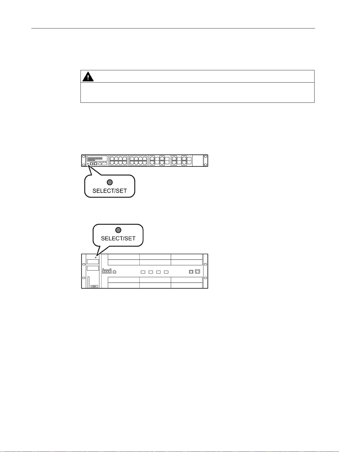
3.2
SELECT/SET button
WARNING
EXPLOSION HAZARD
Position
Setting the display mode
3.2 SELECT/SET button
Do not press the SELECT/SET button when there is an explosive atmosphere.
With a SCALANCE XR-500, the "SELECT/SET" button is on the front of the housing. The
"SELECT/SET" button has several functions that are described below.
Figure 3-1 SELECT/SET button on the SCALANCE XR524-8C SCALANCE XR526-8C is
Figure 3-2 SELECT/SET button on the SCALANCE XR552-12M SCALANCE XR528-6M is
By pressing the button briefly, you change to the display mode of the LED display. You will
find detailed information on the display modes in the sections ""DM1" and "DM2" LEDs for
the display mode (Page 29)" and "Port P1, P2, ... LEDs for the port status (Page 31)".
analogous.
analogous.
SCALANCE XR-500
Operating Instructions, 05/2017, A5E03275845-11
25

Description of the device
Resetting the device to factory defaults
NOTICE
Previous settings
NOTICE
Inadvertent reset
Requirement
Note
Reset despite disabled "SELECT/SET" button
If you have disabled the "Restore Factory Defaults" function for the "SELECT/SET" button in
the co
factory settings
If the function has been disabl
startup phase.
Procedure
Enabling and disabling the button
3.2 SELECT/SET button
If you reset, all the settings you have made will be overwritten by factory defaults.
An inadvertent reset can cause disturbances and failures in a configured network with
further consequences.
● The device is in operation.
● The function "Restore Factory Defaults" is enabled for the "SELECT / SET" button.
nfiguration, this does not apply during the startup phase, see section "Restoring the
(Page 80)".
ed in the configuration, it is only disabled on completion of the
To reset the device to the factory defaults during operation, follow the steps below:
1. Switch to display mode A.
Display mode A is active when the LEDs "DM1" and "DM2" are off.
When the LEDs "DM1" and "DM2" are lit or flashing, you need to press the
"SELECT/SET" button several times briefly until the "DM1" and "DM2" LEDs are off.
If you do not press the "SELECT/SET" button for longer than 1 minute, the device
automatically switches to display mode A.
2. Hold down the "SELECT/SET" button for 12 seconds.
After 9 seconds, the "DM1" and "DM2" LEDs start to flash for 3 seconds. At the same
time, the port LEDs light up one after the other.
If you release the button before the 12 seconds have elapsed, the reset is canceled.
In the configuration, you can enable or disable the button function.
SCALANCE XR-500
26 Operating Instructions, 05/2017, A5E03275845-11

Description of the device
Defining the fault mask
Enabling/disabling the redundancy manager
Initial situation:
Result:
Initial situation:
Result:
3.2 SELECT/SET button
Using the fault mask, you specify an individual "good status" for the connected ports and the
power supply. Deviations from this status are displayed as errors/faults.
To define the fault mask, follow the steps below:
1. Change to display mode D.
Display mode D is active when the "DM1" and "DM2" LEDs are lit green.
If a different display mode is active, press the "SET/SELECT" button several times briefly,
until the "DM1" and "DM2" LEDs are lit green.
2. Hold down the "SELECT/SET" button for 5 seconds.
After 2 seconds, the "DM1" and "DM2" LEDs start to flash for 3 seconds. At the same
time the port LEDs go on one after the other.
After you have pressed the button for 5 seconds, the current settings are stored as the
"good status".
If you release the button before the 5 seconds are up, the previous fault mask is retained.
To enable/disable the redundancy manager, follow the steps below:
1. Change to display mode B.
Display mode B is active when the "DM1" LED is lit green and the and "DM2" LED is off.
If a different display mode is active, press the "SET/SELECT" button several times briefly,
until the "DM1" LED is lit green and the "DM2" LED is off.
2. Hold down the "SELECT/SET" button for 5 seconds.
After 2 seconds, the "DM1", "DM2" and "RM" LEDs start to flash for 3 seconds. At the
same time, the port LEDs light up one after the other.
If you release the button before the 5 seconds have elapsed, the action is canceled.
The result of the action depends on the initial situation:
–
The redundancy manager and media redundancy are disabled.
After enabling the redundancy manager, media redundancy is also enabled.
–
The redundancy manager and media redundancy are enabled.
After disabling the redundancy manager, media redundancy remains enabled.
SCALANCE XR-500
Operating Instructions, 05/2017, A5E03275845-11
27
Description of the device
3.3
LED display
3.3.1
The "RM" LED for the "redundancy manager" function
LED color
LED status
Meaning
-
Off
The device is not a redundancy manager.
The ring is working without problems, monitoring is activated.
has switched through.
3.3.2
The "SB" LED for the standby function
LED color
LED status
Meaning
-
Off
The standby function is disabled.
sive.
Green
Flashing
The standby function is enabled. The standby section is active.
3.3.3
The "F" LED for the fault status
Meaning during device startup
LED color
LED status
Meaning during device startup
-
Off
Device startup was completed successfully.
Red
On
Device startup is not yet completed or errors have occurred.
Red
Flashing
There are errors in the firmware.
Meaning during operation
LED color
LED status
Meaning during operation
closed.
opened.
3.3 LED display
The "RM" LED indicates whether or not the device is a redundancy manager and whether or
not the ring is operating free of error.
Green On The device is a redundancy manager.
Green Flashing The device is a redundancy manager.
An interruption has been detected on the ring and the device
The "SB" LED shows the status of the standby function.
Green On The standby function is enabled. The standby section is pas-
The "F" LED shows the fault/error status of the device.
- Off The device is operating free of errors. The signaling contact is
Red On The device has detected a problem. The signaling contact has
SCALANCE XR-500
28 Operating Instructions, 05/2017, A5E03275845-11
Description of the device
3.3.4
"DM1" and "DM2" LEDs for the display mode
LED color
LED status
Meaning
DM1 LED
DM2 LED
-
Off
Display mode A
Green
On
Off
Display mode B
Green
On
Display mode D
Green
Flashing
Off
Display mode E
Setting the display mode
Pressing SELECT/SET button
starting at display mode A
LED status
Display mode
DM1
DM2
-
Off
Display mode A
Press once
On
Off
Display mode B
Press twice
Off
On
Display mode C
Press three times
On
Display mode D
Press four times
Flashing
Off
Display mode E
3.3.5
"L1" and "L2" LEDs for the power supply
Voltage limit
3.3 LED display
The "DM1" and "DM2" LEDs indicate which display mode is set.
There are 5 display modes (A, B, C, D, and E). Display mode A is the default mode.
Depending on the set display mode, the "L1", "L2" LEDs and the port LEDs show different
information.
Green Off On Display mode C
To set the required display mode, press the "SELECT/SET" button.
If you do not press the "SELECT/SET" button for longer than 1 minute, the device
automatically changes to display mode A.
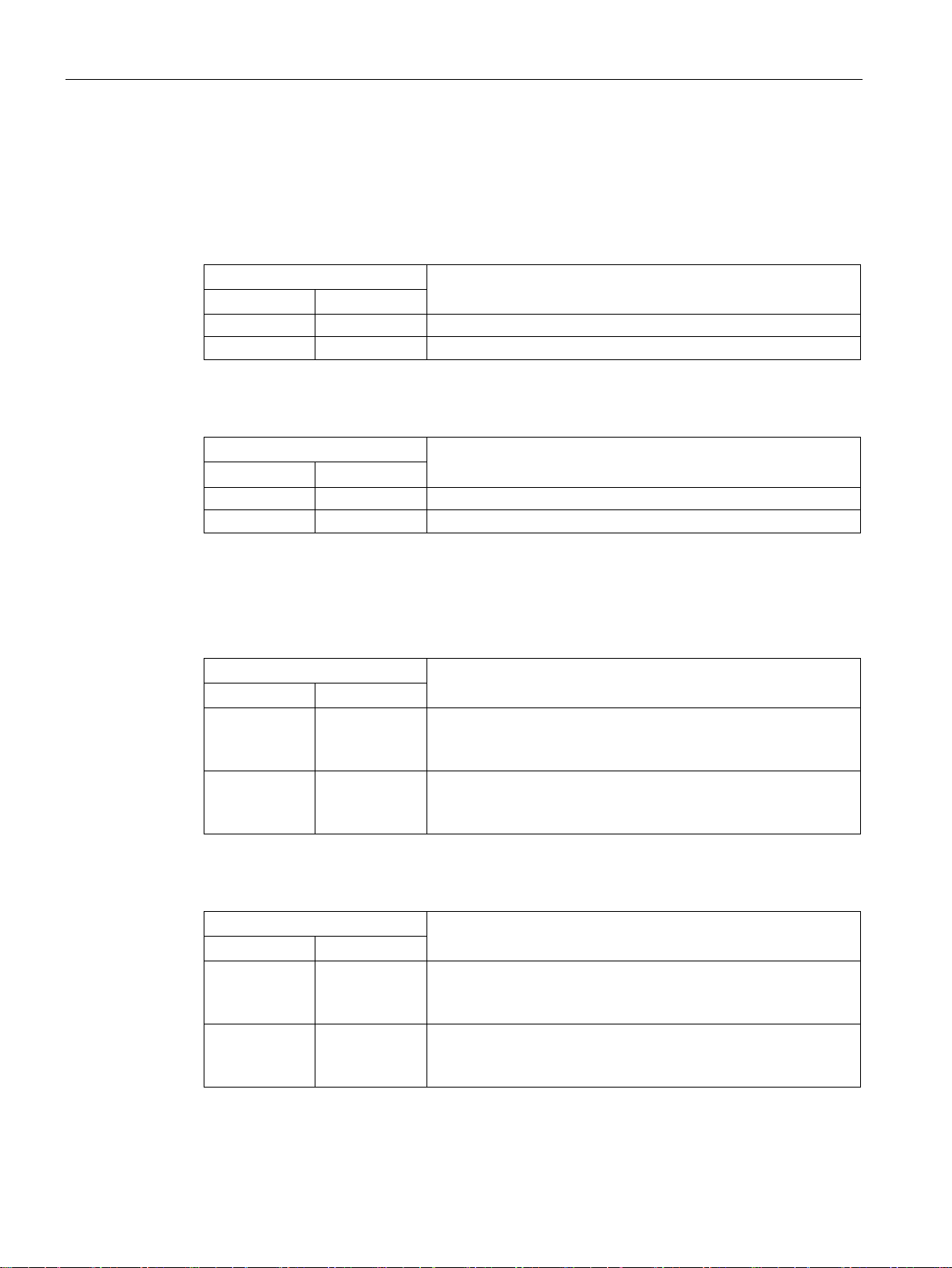
The "L1" and "L2" LEDs indicate the current range of the power supply at connectors L1 and
L2.
The meaning of the "L1" and "L2" LEDs depends on the set display mode, see section
""DM1" and "DM2" LEDs for the display mode (Page 29)".
For devices with 24 VDC, the voltage limit is 17 VDC.
SCALANCE XR-500
Operating Instructions, 05/2017, A5E03275845-11
With devices with 100 to 240 VAC, the voltage limit is 90 VAC.
29
Description of the device
Meaning in display modes A, B, C and E
L1/L2 LED
L1/L2 connector
LED color
LED status
-
Off
Power supply lower than 17 VDC
Green
On
Power supply higher than 17 VDC
L1/L2 LED
L1/L2 connector
LED color
LED status
-
Off
Power supply lower than 90 VAC
Meaning in display mode D
L1/L2 LED
L1/L2 connector
LED color
LED status
If the power supply falls below 17 VDC, the signaling contact does
not respond.
responds.
L1/L2 LED
L1/L2 connector
LED color
LED status
If the power supply falls below 90 VAC, the signaling contact does
not respond.
sponds.
3.3 LED display
In display modes A, B, C and D, from the "L1" and "L2" LEDs you can see whether the
power supply is higher or lower than a certain voltage limit.
Table 3- 1 For devices with a 24 VDC power supply
Table 3- 2 Power supply for devices with 100 to 240 VAC
Green On Power supply higher than 90 VAC
In display mode D, the "L1" and "L2" LEDs indicate whether the power supply is monitored.
Table 3- 3 Monitoring for devices with 24 VDC
- Off Power supply is not monitored.
Green On Power supply is monitored.
If the power supply falls below 17 VDC, the signaling contact
Table 3- 4 Monitoring for devices with 100 to 240 VAC
- Off Power supply is not monitored.
Green On Power supply is monitored.
SCALANCE XR-500
30 Operating Instructions, 05/2017, A5E03275845-11
If the power supply falls below 90 VAC, the signaling contact re-
 Loading...