

Page 1

Preface, Contents
SIMATIC
Standard Software
for S7-300 and S7-400
PID Control
User Manual
Introduction
Parameter Assignment
Function Blocks
References
Glossary, Index
1
2
3
A
C79000-G7076-C516-01
Page 2

Safety Guidelines
!
!
!
This manual contains notices which you should observe to ensure your own personal safety, as well as to
protect the product and connected equipment. These notices are highlighted in the manual by a warning
triangle and are marked as follows according to the level of danger:
Danger
indicates that death, severe personal injury or substantial property damage will result if proper precautions are
not taken.
Warning
indicates that death, severe personal injury or substantial property damage can result if proper precautions are
not taken.
Caution
indicates that minor personal injury or property damage can result if proper precautions are not taken.
Note
draws your attention to particularly important information on the product, handling the product, or to a particular
part of the documentation.
Qualified Personnel
Correct Usage
The device/system may only be set up and operated in conjunction with this manual.
Only qualified personnel should be allowed to install and work on this equipment. Qualified persons are
defined as persons who are authorized to commission, to ground, and to tag circuits, equipment, and systems in accordance with established safety practices and standards.
Note the following:
Warning
!
Trademarks
The reproduction, transmission or use of this document or its contents is
not permitted without express written authority. Of fenders will be liable for
damages. All rights, including rights created by patent grant or registration
of a utility model or design, are reserved.
This device and its components may only be used for the applications described in the catalog or the technical
description, and only in connection with devices or components from other manufacturers which have been
approved or recommended by Siemens.
This product can only function correctly and safely if it is transported, stored, set up, and installed correctly, and
operated and maintained as recommended.
SIMATICR and SINECR are registered trademarks of SIEMENS AG.
Third parties using for their own purposes any other names in this document which refer to
trademarks might infringe upon the rights of the trademark owners.
Disclaimer of LiabilityCopyright E Siemens AG 1996 All rights reserved
We have checked the contents of this manual for agreement with the
hardware and software described. Since deviations cannot be precluded
entirely, we cannot guarantee full agreement. However, the data in this
manual are reviewed regularly and any necessary corrections included in
subsequent editions. Suggestions for improvement are welcomed.
Siemens AG
Automation Group
Industrial Automation Systems
Postfach 4848, D-90327 Nürnberg
Siemens Aktiengesellschaft C79000-G7076-C516
Standard Software for S7-300 and S7-400 – PID Control
T echnical data subject to change.
E Siemens AG 1996
Page 3
Preface
Purpose
Audience
Structure of
“PID Control”
This manual supports you when working with the controller blocks of PID
Control.
The manual introduces you to the functions of the controller blocks and
familiarizes you with the user interface for assigning parameters to the
blocks. This user interface includes online help, that further supports you
when assigning parameters to the blocks.
This manual is intended for the following readers:
– S7 programmers
– Programmers of closed-loop control systems
– Operators
– Service personnel
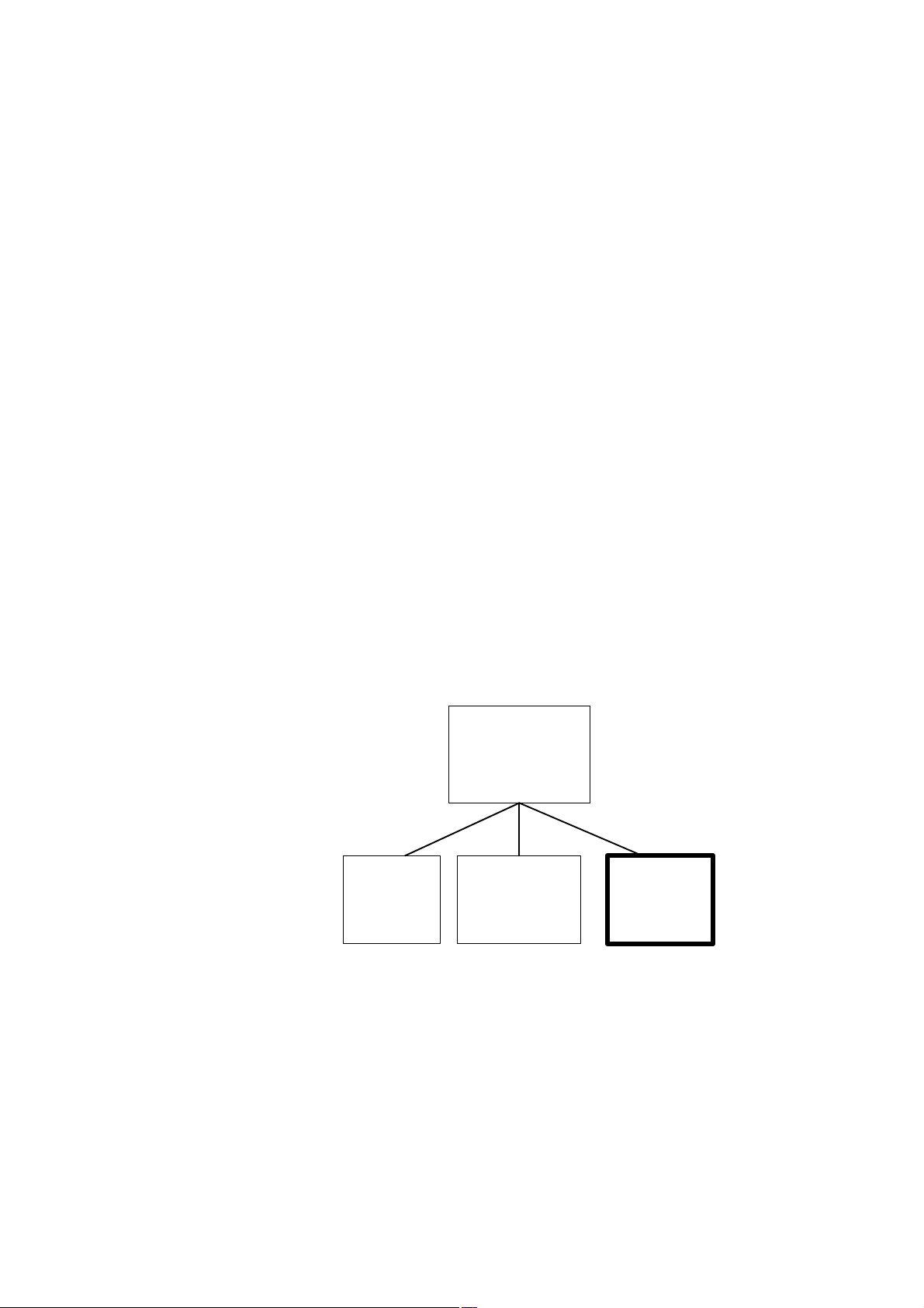
PID Control
S7-300 and S7-400
Function
blocks
PID Control
The “PID Control” software package includes the following components:
– The function blocks CONT_C, CONT_S and PULSEGEN.
– The parameter assignment user interface for configuring the controller
blocks.
– The manual consisting mainly of a description of the function blocks.
Standard Software for S7-300 and S7-400 – PID Control
C79000-G7076-C516-01
Parameter
assignment user
interface
PID Control
Electronic
manual
PID Control
iii
Page 4

Preface
Content of the
Manual
Chapter
1
Provides you with an overview of PID Control
Further
Information
Additional
Assistance
Chapter
2
Chapter
3
Explains how to call the parameter assignment user interface
Describes the function blocks FB 41 “CONT_C”, FB 42 “CONT_S”
and FB 43 “PULSEGEN”
This manual is designed as a reference work providing you with the
information you require about PID Control. Depending on your experience,
you may well need further information that can be found in the manuals /70/,
/71/, /100/, /101/, /231/, /232/, /234/.
If you have any questions regarding the use or application of PID Control,
please contact the Siemens representative in your area.
You will find a list of addresses in the Appendix “SIEMENS Worldwide“ in
the “S7-400 Programmable Controller, Hardware and Installation” manual.
If you have any questions or comments on this manual, please fill out the
remarks form at the end of the manual and return it to the address shown on
the form. We would be grateful if you could also take the time to answer the
questions giving your personal opinion of the manual.
Siemens also offers a number of training courses to introduce you to the
SIMATIC S7 automation system. Please contact your regional training center
or the central training center in Nuremberg, Germany for details.
T el. +49-911-985-3154.
iv
Standard Software for S7-300 and S7-400 – PID Control
C79000-G7076-C516-01
Page 5

Contents
1 Introduction 1-1. . . . . . . . . . . . . . . . . . . . . . . . . . . . . . . . . . . . . . . . . . . . . . . . . . . . . . . . . . . . .
2 Parameter Assignment 2-1. . . . . . . . . . . . . . . . . . . . . . . . . . . . . . . . . . . . . . . . . . . . . . . . . . .
3 Function Blocks 3-1. . . . . . . . . . . . . . . . . . . . . . . . . . . . . . . . . . . . . . . . . . . . . . . . . . . . . . . . .
3.1 Continuous Control with FB41 “CONT_C” 3-2. . . . . . . . . . . . . . . . . . . . . . . . . . .
3.2 Step Control with FB42 “CONT_S” 3-9. . . . . . . . . . . . . . . . . . . . . . . . . . . . . . . . .
3.3 Pulse Generation with FB43 “PULSEGEN” 3-15. . . . . . . . . . . . . . . . . . . . . . . . . .
3.4 Example of Using PULSEGEN 3-24. . . . . . . . . . . . . . . . . . . . . . . . . . . . . . . . . . . . .
A References A-1. . . . . . . . . . . . . . . . . . . . . . . . . . . . . . . . . . . . . . . . . . . . . . . . . . . . . . . . . . . . . .
Index Index-1. . . . . . . . . . . . . . . . . . . . . . . . . . . . . . . . . . . . . . . . . . . . . . . . . . . . . . . . . . . . . . . . . .
Standard Software for S7-300 and S7-400 – PID Control
C79000-G7076-C516-01
v
Page 6

vi
Standard Software for S7-300 and S7-400 – PID Control
C79000-G7076-C516-01
Page 7

Introduction
1
The Concept of
PID Control
Basic Functions
Applications
The function blocks (FBs) of the PID Control package consist of controller
blocks for continuous control (CONT_C), for step control (CONT_S), and
the FB for pulse duration modulation (PULSEGEN).
The controller blocks implement a purely software controller with the block
providing the entire functionality of the controller. The data required for
cyclic calculation is stored in data blocks assigned to the FB. This allows the
FBs to be called as often as necessary.
FB PULSEGEN is used in conjunction with FB CONT_C to implement a
controller with a pulse output for proportional actuators.
A controller created with the FBs consists of a series of subfunctions that you
can activate or deactivate. In addition to the actual controller with its PID
algorithm, integrated functions are also available for processing the setpoint
and process variable and for adapting the calculated manipulated variable.
A controller implemented with the two controller blocks is not restricted to
any particular application. The performance of the controller and its
processing speed is only dependent on the performance of the CPU being
used.
With any given CPU, a compromise must be made between the number of
controllers and the frequency at which the individual controllers are
processed. The speed at which the control loops must be processed, in other
words, the more often the manipulated variables must be calculated per unit
of time, determines the number of controllers that can be installed (faster
loops mean less controllers).
There are no restrictions in terms of the type of process that can be
controlled. Both slow processes (temperatures, tank levels etc.) and very fast
processes (flow rate, motor speed etc.) can be controlled.
Process Analysis
Standard Software for S7-300 and S7-400 – PID Control
C79000-G7076-C516-01
Note
The static behavior (gain) and the dynamic characteristics (time lag, dead
time, reset time etc.) of the process to be controlled have a significant
influence on the structuring and design of the controller and on the selection
of the dimensions of its static (P component) and its dynamic (I and D
components) parameters.
Precise knowledge of the type and characteristic data of the process to be
controlled is essential.
1-1
Page 8

Introduction
Choice of
Controller
Creating the
Controller
Online Help
Further
Information
Note
The characteristics of control loops are decided by the given physical
characteristics of the process or machine being controlled and can only be
modified in minor ways. Good control quality is only possible if you choose
the controller type most suited to your situation and adapt it to the time
response of the process.
You can create a controller (structuring, parameter assignment, and call in
the system program) largely without programming. Knowledge of STEP 7 is,
however, necessary.
The STEP 7 online help also provides you with information about the various
FBs.
PID Control is a subset of Standard Control. For further information about
the standard controller, refer to /350/.
1-2
Standard Software for S7-300 and S7-400 – PID Control
C79000-G7076-C516-01
Page 9

Parameter Assignment
2
Calling the
Parameter
Assignment User
Interface
Online Help
You call the parameter assignment user interface of PID Control under
Windows 95 using the following menu options:
S Start " SIMATIC " STEP 7 V3 " PID Control Parameter
Assignment
In the first dialog, you can either open an existing instance data block (DB)
for an FB41 “CONT_C” or FB42 “CONT_S” or create a new data block as
the instance data block. If you create a new instance data block, you will be
prompted to assign the instance DB to an FB.
FB43 “PULSEGEN” does not have a parameter assignment user interface.
You must set its parameters with STEP 7 tools.
Note
Using the parameter assignment user interface of PID Control, you can also
assign parameters for the integrated control of the CPU 314 IFM. In this
case, you create instance DBs that you assign to SFB41 or SFB42.
Online help is available in the parameter assignment user interface to support
you when you assign parameters to the controller blocks. You can call the
online help in three ways:
S Using the menu option Help " Contents...
S By pressing the F1 key
S By clicking the Help button in the parameter assignment dialogs
Standard Software for S7-300 and S7-400 – PID Control
C79000-G7076-C516-01
2-1
Page 10

Parametrierung
2-2
Standard Software for S7-300 and S7-400 – PID Control
C79000-G7076-C516-01
Page 11

Function Blocks
Note
The function blocks described in this chapter (FB41 to FB43) have only been
released for S7/C7 CPUs with cyclic interrupt levels.
3
Chapter
Overview
Section Description Page
3.1 Continuous Control with FB41 “CONT_C” 3-2
3.2 Step Control with FB42 “CONT_S” 3-9
3.3 Pulse Generation with FB43 “PULSEGEN” 3-15
3.4 Example of Using PULSEGEN 3-24
Standard Software for S7-300 and S7-400 – PID Control
C79000-G7076-C516-01
3-1
Page 12

Function Blocks
3.1 Continuous Control with FB41 “CONT_C”
Introduction
Application
Description
FB “CONT_C” is used on SIMATIC S7 programmable controllers to control
technical processes with continuous input and output variables. During
parameter assignment, you can activate or deactivate subfunctions of the PID
controller to adapt the controller to the process.
You can use the controller as a PID fixed setpoint controller or in multi-loop
controls as a cascade, blending or ratio controller. The functions of the
controller are based on the PID control algorithm of the sampling controller
with an analog signal, if necessary extended by including a pulse generator
stage to generate pulse duration modulated output signals for two or three
step controllers with proportional actuators.
Apart from the functions in the setpoint and process value branches, the FB
implements a complete PID controller with continuous manipulated variable
output and the option of influencing the manipulated value manually.
In the following, you will find a detailed description of the subfunctions:
Setpoint Branch
The setpoint is entered in floating-point format at the SP_INT input.
Process Variable Branch
The process variable can be input in the peripheral (I/O) or floating-point
format. The CRP_IN function converts the PV_PER peripheral value to a
floating-point format of -100 to +100 % according to the following formula:
Output of CRP_IN = PV_PER
100
27648
The PV_NORM function normalizes the output of CRP_IN according to the
following formula:
Output of PV_NORM = (output of CRP_IN) PV_FAC + PV_OFF
PV_FAC has a default of 1 and PV_OFF a default of 0.
Error Signal
The difference between the setpoint and process variable is the error signal.
T o suppress a small constant oscillation due to the manipulated variable
quantization (for example in pulse duration modulation with PULSEGEN), a
dead band is applied to the error signal (DEADBAND). If DEADB_W = 0,
the dead band is switched off.
PID Algorithm
The PID algorithm operates as a position algorithm. The proportional,
integral (INT), and derivative (DIF) actions are connected in parallel and can
be activated or deactivated individually. This allows P, PI, PD, and PID
controllers to be configured. Pure I and D controllers are also possible.
3-2
Standard Software for S7-300 and S7-400 – PID Control
C79000-G7076-C516-01
Page 13

Function Blocks
Manual Value
It is possible to switch over between a manual and an automatic mode. In the
manual mode, the manipulated variable is corrected to a manually selected
value. The integrator (INT) is set internally to LMN - LMN_P - DISV and
the derivative unit (DIF) to 0 and matched internally. This means that a
switchover to the automatic mode does not cause any sudden change in the
manipulated value.
Manipulated Value
The manipulated value can be limited to a selected value using the
LMNLIMIT function. Signaling bits indicate when a limit is exceeded by the
input variable.
The LMN_NORM function normalizes the output of LMNLIMIT according
to the following formula:
LMN = (output of LMNLIMIT) LMN_FAC + LMN_OFF
LMN_FAC has the default 1 and LMN_OFF the default 0.
The manipulated value is also available in the peripheral format. The
CRP_OUT function converts the floating-point value LMN to a peripheral
value according to the following formula:
LMN_PER = LMN
27648
100
Modes
Error
Information
Feedforward Control
A disturbance variable can be fed forward at the DISV input.
Complete Restart/Restart
FB41 “CONT_C” has a complete restart routine that is run through when the
input parameter COM_RST = TRUE is set.
During startup, the integrator is set internally to the initialization value
I_ITVAL. When it is called in a cyclic interrupt priority class, it then
continues to work starting at this value.
All other outputs are set to their default values.
The block does not check for errors internally. The error output parameter
RET_VAL is not used.
Standard Software for S7-300 and S7-400 – PID Control
C79000-G7076-C516-01
3-3
Page 14

Function Blocks
Block Diagram
SP_INT
PV_IN
PV_PER
CRP_IN
INT
TI, INT_HOLD,
I_ITL_ON,
I_ITLVAL
DIF
TD, TM_LAG
%
PV_NORM
PV_FAC,
PV_OFF
0.0
0.0
0.0
1
0
1
0
1
0
PVPER_ON
P_SEL
I_SEL
D_SEL
DEADBAND
0
1
+
-
DEADB_W
PV
LMN_P
DISV
+
LMN_I
LMN_D
GAIN
X
ER
+
MAN
MAN_ON
1
0
LMNLIMIT
LMN_HLM,
LMN_LLM
Figure 3-1 Block Diagram of CONT_C
3-4
QLMN_HLM
QLMN_LLM
LMN
LMN_NORM
LMN_FAC,
LMN_OFF
Standard Software for S7-300 and S7-400 – PID Control
CRP_OUT
%
C79000-G7076-C516-01
LMN_PER
Page 15

Function Blocks
Input Parameters
T able 3-1 contains the description of the input parameters for FB41
“CONT_C”.
Table 3-1 Input Parameters (INPUT) for FB 41 “CONT_C”
Parameter
Data
Type
COM_RST BOOL FALSE
MAN_ON BOOL TRUE
PVPER_ON BOOL FALSE
P_SEL BOOL TRUE
I_SEL BOOL TRUE
INT_HOLD BOOL FALSE
I_ITL_ON BOOL FALSE
D_SEL BOOL FALSE
CYCLE TIME
SP_INT REAL
PV_IN REAL
PV_PER WORD
Range of
Values
>= 1ms
-100.0...100.
0 (%)
or phys.
value 1)
-100.0...100.
0 (%)
or phys.
value 1)
Default Description
COMPLETE RESTART
The block has a complete restart routine that is processed when
the input “complete restart” is set.
MANUAL VALUE ON
If the input “manual value on” is set, the control loop is
interrupted. A manual value is set as the manipulated value.
PROCESS VARIABLE PERIPHERAL ON
If the process variable is read from the I/Os, the input PV_PER
must be connected to the I/Os and the input “process variable
peripheral on” must be set.
PROPORTIONAL ACTION ON
The PID actions can be activated or deactivated individually in
the PID algorithm. The P action is on when the input
“proportional action on” is set.
INTEGRAL ACTION ON
The PID actions can be activated or deactivated individually in
the PID algorithm. The I action is on when the input “integral
action on” is set.
INTEGRAL ACTION HOLD
The output of the integrator can be “frozen” by setting the input
“integral action hold”.
INITIALIZATION OF THE INTEGRAL ACTION
The output of the integrator can be connected to the input
I_ITL_VAL by setting the input “initialization of the integral
action on”.
DERIVATIVE ACTION ON
The PID actions can be activated or deactivated individually in
the PID algorithm. The D action is on when the input
“derivative action on” is set.
SAMPLING TIME
T#1s
The time between the block calls must be constant. The
“sampling time” input specifies the time between block calls.
0.0
INTERNAL SETPOINT
The “internal setpoint” input is used to specify a setpoint.
PROCESS VARIABLE IN
0.0
An initialization value can be set at the “process variable in”
input or an external process variable in floating point format can
be connected.
W#16#00
00
PROCESS VARIABLE PERIPHERAL
The process variable in the I/O format is connected to the
controller at the “process variable peripheral” input.
Standard Software for S7-300 and S7-400 – PID Control
C79000-G7076-C516-01
3-5
Page 16

Function Blocks
Table 3-1 Input Parameters (INPUT) for FB 41 “CONT_C”, continued
Parameter DescriptionDefault
Data
Type
MAN REAL
Range of
Values
-100.0...100.
0 (%)
or phys.
value 2)
0.0
GAIN REAL 2.0
TI TIME
>= CYCLE
T#20s
TD TIME >= CYCLE T#10s
TM_LAG TIME >= CYCLE/2 T#2s
>= 0.0 (%)
DEADB_W REAL
LMN_HLM REAL
LMN_LLM REAL
or phys.
value 1)
LMN_LLM
...100.0 (%)
or phys.
value 2)
-100.0...
LMN_HLM
(%)
or phys.
value 2)
0.0
100.0
0.0
PV_FAC REAL 1.0
PV_OFF REAL 0.0
LMN_FAC REAL 1.0
LMN_OFF REAL 0.0
MANUAL VALUE
The “manual value” input is used to set a manual value using the
operator interface functions.
PROPORTIONAL GAIN
The “proportional value” input specifies the controller gain.
RESET TIME
The “reset time” input determines the time response of the
integrator.
DERIVATIVE TIME
The “derivative time” input determines the time response of the
derivative unit.
TIME LAG OF THE DERIVATIVE ACTION
The algorithm of the D action includes a time lag that can be
assigned at the “time lag of the derivative action” input.
DEAD BAND WIDTH
A dead band is applied to the error. The “dead band width”
input determines the size of the dead band.
MANIPULATED VALUE HIGH LIMIT
The manipulated value is always limited by an upper and lower
limit. The “manipulated value high limit”input specifies the
upper limit.
MANIPULATED VALUE LOW LIMIT
The manipulated value is always limited by an upper and lower
limit. The “manipulated value low limit”input specifies the
lower limit.
PROCESS VARIABLE FACTOR
The “process variable factor” input is multiplied by the process
variable. The input is used to adapt the process variable range.
PROCESS VARIABLE OFFSET
The “process variable offset” input is added to the process
variable. The input is used to adapt the process variable range.
MANIPULATED VALUE FACTOR
The “manipulated value factor” input is multiplied by the
manipulated value. The input is used to adapt the manipulated
value range.
MANIPULATED VALUE OFFSET
The “manipulated value offset” is added to the manipulated
value. The input is used to adapt the manipulated value range.
3-6
Standard Software for S7-300 and S7-400 – PID Control
C79000-G7076-C516-01
Page 17

Table 3-1 Input Parameters (INPUT) for FB 41 “CONT_C”, continued
Function Blocks
Parameter DescriptionDefault
Data
Type
I_ITLVAL REAL
DISV REAL
1) Parameters in the setpoint and process variable branches with the same unit
2) Parameters in the manipulated value branch with the same unit
Output
Parameters
Range of
Values
-100.0...100.
0 (%)
or phys.
value 2)
-100.0...100.
0 (%)
or phys.
value 2)
0.0
0.0
INITIALIZATION VALUE OF THE INTEGRAL ACTION
The output of the integrator can be set at input I_ITL_ON. The
initialization value is applied to the input “initialization value of
the integral action”.
DISTURBANCE VARIABLE
For feedforward control, the disturbance variable is connected to
input “disturbance variable”.
T able 3-2 contains the description of the output parameters for FB41
“CONT_C”.
Table 3-2 Output Parameters (OUTPUT) for FB 41 “CONT_C”
Parameter
Data
Type
Range of
Values
Default Description
LMN REAL 0.0 MANIPULATED VALUE
The effective manipulated value is output in floating point
format at the “manipulated value” output.
LMN_PER WORD W#16#0000 MANIPULATED VALUE PERIPHERAL
The manipulated value in the I/O format is connected to the
controller at the “manipulated value peripheral” output.
QLMN_HLM BOOL FALSE HIGH LIMIT OF MANIPULATED VALUE REACHED
The manipulated value is always limited to an upper and
lower limit. The output “high limit of manipulated value
reached” indicates that the upper limit has been exceeded.
QLMN_LLM BOOL FALSE LOW LIMIT OF MANIPULATED VALUE REACHED
The manipulated value is always limited to an upper and
lower limit. The output “low limit of manipulated value
reached” indicates that the lower limit has been exceeded.
LMN_P REAL 0.0 PROPORTIONAL COMPONENT
The “proportional component” output contains the
proportional component of the manipulated variable.
LMN_I REAL 0.0 INTEGRAL COMPONENT
The “integral component” output contains the integral
component of the manipulated value.
LMN_D REAL 0.0 DERIVATIVE COMPONENT
The “derivative component” output contains the derivative
component of the manipulated value.
Standard Software for S7-300 and S7-400 – PID Control
C79000-G7076-C516-01
3-7
Page 18

Function Blocks
Table 3-2 Output Parameters (OUTPUT) for FB 41 “CONT_C”, continued
Parameter DescriptionDefault
PV REAL 0.0 PROCESS VARIABLE
ER REAL 0.0 ERROR SIGNAL
Data
Type
Range of
Values
The effective process variable is output at the “process
variable” output.
The effective error is output at the “error signal” output.
3-8
Standard Software for S7-300 and S7-400 – PID Control
C79000-G7076-C516-01
Page 19

3.2 Step Control with FB42 “CONT_S”
Function Blocks
Introduction
Application
Description
FB42 “CONT_S” is used on SIMATIC S7 programmable logic controllers to
control technical processes with digital manipulated value output signals for
integrating actuators. During parameter assignment, you can activate or
deactivate subfunctions of the PI step controller to adapt the controller to the
process.
You can use the controller as a PI fixed setpoint controller or in secondary
control loops in cascade, blending or ratio controllers, however not as the
primary controller. The functions of the controller are based on the PI control
algorithm of the sampling controller supplemented by the functions for
generating the binary output signal from the analog actuating signal.
Apart from the functions in the process value branch, the FB implements a
complete PI controller with a digital manipulated value output and the option
of influencing the manipulated value manually. The step controller operates
without a position feedback signal.
In the following you will find the description of the partial functions:
Setpoint Branch
The setpoint is entered in floating-point format at the SP_INT input.
Process Variable Branch
The process variable can be input in the peripheral (I/O) or floating-point
format. The CRP_IN function converts the PV_PER peripheral value to a
floating-point format of -100 to +100 % according to the following formula:
Output of CRP_IN = PV_PER
The PV_NORM function normalizes the output of CRP_IN according to the
following formula:
Output of PV_NORM = (output of CRP_IN) PV_FAC + PV_OFF
PV_FAC has a default of 1 and PV_OFF a default of 0.
Error Signal
The difference between the setpoint and process variable is the error signal.
T o suppress a small constant oscillation due to the manipulated variable
quantization (for example due to a limited resolution of the manipulated
value by the actuator valve), a dead band is applied to the error signal
(DEADBAND). If DEADB_W = 0, the dead band is switched off.
Standard Software for S7-300 and S7-400 – PID Control
C79000-G7076-C516-01
100
27648
3-9
Page 20

Function Blocks
PI Step Algorithm
The FB operates without a position feedback signal. The I action of the PI
algorithm and the assumed position feedback signal are calculated in one
integrator (INT) and compared with the remaining P action as a feedback
value. The difference is applied to a three-step element (THREE_ST) and a
pulse generator (PULSEOUT) that creates the pulses for the actuator. The
switching frequency of the controller can be reduced by adapting the
threshold on of the three-step element.
Feedforward Control
A disturbance variable can be fed forward at the DISV input.
Modes
Error
Information
Complete Restart/Restart
FB42 “CONT_S” has a complete restart routine that is run through when the
input parameter COM_RST = TRUE is set.
All other outputs are set to their default values.
The block does not check for errors internally. The error output parameter
RET_VAL is not used.
3-10
Standard Software for S7-300 and S7-400 – PID Control
C79000-G7076-C516-01
Page 21

Block Diagram
SP_INT
PV_IN
PV_PER
CRP_IN
%
PV_NORM
PV_FAC
PV_OFF
PVPER_ON
0
1
Function Blocks
DEADBAND
+
–
DEADB_W
PV
GAIN
X
ER
LMNR_HS
LMNR_LS
LMNUP
LMNDN
LMNS_ON
1
DISV
+
THREE_ST
adaptiv
–
MTR_TM
LMNS_ON
1/TI
0
1
0
1
0.0
0
X
Figure 3-2 Block Diagram of CONT_S
AN
D
AN
D
INT
PULSEOUT
PULSE_TM,
BREAK_TM
INT
LMNLIMIT
LMNR_SIM
1
0
1
0
1/MTR_TM
100.0 ,
0.0
QLMNUP
QLMNDN
+
X
LMNRS_ON
,LMNRSVAL
AN
D
AN
D
100.0
0.0
–100.0
0.0
OR
+
1
0.0
0
–
Standard Software for S7-300 and S7-400 – PID Control
C79000-G7076-C516-01
3-11
Page 22

Function Blocks
Input Parameters
T able 3-3 contains the description of the input parameters for FB42
“CONT_S”.
Table 3-3 Input Parameters (INPUT) for FB 42 “CONT_S”
Parameter
Data
Type
COM_RST BOOL FALSE COMPLETE RESTART
LMNR_HS BOOL FALSE HIGH LIMIT OF POSITION FEEDBACK SIGNAL
LMNR_LS BOOL FALSE LOW LIMIT OF POSITION FEEDBACK SIGNAL
LMNS_ON BOOL FALSE MANUAL ACTUATING SIGNALS ON
LMNUP BOOL FALSE ACTUATING SIGNALS UP
LMNDN BOOL FALSE ACTUATING SIGNALS DOWN
PVPER_ON BOOL FALSE PROCESS VARIABLE PERIPHERAL ON
CYCLE TIME
SP_INT REAL
PV_IN REAL -100.0...100.0
PV_PER WORD W#16#0000 PROCESS VARIABLE PERIPHERAL
Range of
Values
>= 1ms
-100.0...100.0
(%)
or phys. value
1)
(%)
or phys. value
1)
Default Description
The block has a complete restart routine that is processed
when the input “complete restart” is set.
The “actuator at upper limit stop” signal is connected to the
“high limit of position feedback signal” input.
LMNR_HS=TRUE means the actuator is at upper limit
stop.
The “actuator at lower limit stop” signal is connected to the
“low limit of position feedback signal” input.
LMNR_LS=TRUE means the actuator is at lower limit stop.
The actuating signal processing is switched to manual at the
“manual actuating signals on” input..
With manual actuating value signals, the output signal
QLMNUP is set at the input “actuating signals up”.
With manual actuating value signals, the output signal
QLMNDN is set at the input “actuating signals down”.
If the process variable is read in from the I/Os, the input
PV_PER must be connected to the I/Os and the input
“process variable peripheral on” must be set.
T#1s SAMPLING TIME
The time between the block calls must be constant. The
“sampling time” input specifies the time between block
calls.
0.0 INTERNAL SETPOINT
The “internal setpoint” input is used to specify a setpoint.
0.0 PROCESS VARIABLE IN
An initialization value can be set at the “process variable in”
input or an external process variable in floating point format
can be connected.
The process variable in the I/O format is connected to the
controller at the “process variable peripheral” input.
3-12
Standard Software for S7-300 and S7-400 – PID Control
C79000-G7076-C516-01
Page 23

Table 3-3 Input Parameters (INPUT) for FB 42 “CONT_S”, Fortsetzung
Function Blocks
Parameter DescriptionDefault
Data
Type
Range of
Values
GAIN REAL 2.0 PROPORTIONAL GAIN
The “proportional gain” input sets the controller gain.
TI TIME
>= CYCLE
T#20s RESET TIME
The “reset time” input determines the time response of the
integrator.
DEADB_W REAL 0.0...100.0
(%)
or phys. value
1)
1.0
DEAD BAND WIDTH
A dead band is applied to the error. The “dead band width”
input determines the size of the dead band.
PV_FAC REAL 1.0 PROCESS VARIABLE FACTOR
The “process variable factor” input is multiplied by the
process variable. The input is used to adapt the process
variable range.
PV_OFF REAL 0.0 PROCESS VARIABLE OFFSET
The “process variable offset” input is added to the process
variable. The input is used to adapt the process variable
range.
PULSE_TM TIME >= CYCLE T#3s MINIMUM PULSE TIME
A minimum pulse duration can be assigned with the
parameter “minimum pulse time”.
BREAK_TMTIME >= CYCLE T#3s MINIMUM BREAK TIME
A minimum break duration can be assigned with the
parameter “minimum break time”.
MTR_TM TIME >= CYCLE T#30s MOTOR ACTUATING TIME
The time required by the actuator to move from limit stop to
limit stop is entered at the “motor actuating time” parameter.
DISV REAL -100.0...100.0
(%)
or phys. value
2)
0.0 DISTURBANCE VARIABLE
For feedforward control, the disturbance variable is
connected to input “disturbance variable”.
1) Parameters in the setpoint and process variable branches with the same unit
2) Parameters in the manipulated value branch with the same unit
Standard Software for S7-300 and S7-400 – PID Control
C79000-G7076-C516-01
3-13
Page 24

Function Blocks
Output Parameters
T able 3-4 contains the description of the output parameters for FB42
“CONT_S”.
Table 3-4 Output Parameters (OUTPUT) for FB42 “CONT_S”
Parameter
QLMNUP BOOL FALSE ACTUATING SIGNAL UP
QLMNDN BOOL FALSE ACTUATING SIGNAL DOWN
PV REAL 0.0 PROCESS VARIABLE
ER REAL 0.0 ERROR SIGNAL
Data
Type
Range of
Values
Default Description
If the output “actuating signal up” is set, the actuating valve
is opened.
If the output “actuating signal down” is set, the actuating
valve is opened.
The effective process variable is output at the “process
variable” output.
The effective error is output at the “error signal” output.
3-14
Standard Software for S7-300 and S7-400 – PID Control
C79000-G7076-C516-01
Page 25

3.3 Pulse Generation with FB43 “PULSEGEN”
Function Blocks
Introduction
Application
Description
FB43 “PULSEGEN” is used to structure a PID controller with pulse output
for proportional actuators
Using FB43 “PULSEGEN”, PID two or three step controllers with pulse
duration modulation can be configured. The function is normally used in
conjunction with the continuous controller ~CONT_C”.
CONT_C
LMN
PULSEGEN
INV
The PULSEGEN function transforms the input variable INV ( = manipulated
value of the PID controller) by modulating the pulse duration into a pulse
train with a constant period, corresponding to the cycle time at which the
input variable is updated and which must be assigned in PER_TM.
The duration of a pulse per period is proportional to the input variable. The
cycle assigned to PER_TM is not identical to the processing cycle of the FB
“PULSEGEN”. The PER_TM cycle is made up of several processing cycles
of FB “PULSEGEN”, whereby the number of FB “PULSEGEN” calls per
PER_TM cycle is the yardstick for the accuracy of the pulse duration
modulation.
INV
100
(LMN)
50
0
QPOS_P
1
0
Figure 3-3 Pulse Duration Modulation
Standard Software for S7-300 and S7-400 – PID Control
C79000-G7076-C516-01
30
PULSEGEN cycle
PER_TM
(= CONT_C cycle)
80
50
t
t
3-15
Page 26

Function Blocks
Block Diagram
An input variable of 30% and 10 FB “PULSEGEN” calls per PER_TM
means the following:
– “One” at the QPOS output for the first three calls of FB
“PULSEGEN” (30% of 10 calls)
– “Zero”at the QPOS output for seven further calls of FB “PULSEGEN”
(70% of 10 calls)
POS_P_ON
NEG_P_ON
Accuracy of the
Manipulated Value
SYN_ON,
STEP3_ON,
ST2BI_ON
#
INV
PER_TM,
P_B_TM,
RATIOFAC
Figure 3-4 Block Diagram of PULSEGEN
MAN_ON
1
0
QPOS_P
QNEG_P
With a “sampling ratio” of 1:10 (CONT_C calls to PULSEGEN calls) the
accuracy of the manipulated value in this example is restricted to10%, in
other words, set input values INV can only be simulated by a pulse duration
at the QPOS output in steps of 10 %.
The accuracy is increased as the number of FB “PULSEGEN” calls per
CONT_C call is increased.
If PULSEGEN is called, for example 100 times more often than CONT_C, a
resolution of 1 % of the manipulated value range is achieved.
Automatic
Synchronization
3-16
Note
The call frequency must be programmed by the user.
It is possible to synchronize the pulse output with the block that updates the
input variable INV (for example CONT_C). This ensures that a change in the
input variable is output as quickly as possible as a pulse.
The pulse generator evaluates the input value INV at intervals corresponding
to the period PER_TM and converts the value into a pulse signal of
corresponding length.
Standard Software for S7-300 and S7-400 – PID Control
C79000-G7076-C516-01
Page 27

Function Blocks
Since, however, INV is usually calculated in a slower cyclic interrupt class,
the pulse generator should start the conversion of the discrete value into a
pulse signal as soon as possible after the updating of INV.
T o allow this, the block can synchronize the start of the period using the
following procedure:
If INV changes and if the block call is not in the first or last two call cycles
of a period, the synchronization is performed. The pulse duration is recalculated and in the next cycle is output with a new period (see Figure 3-5).
LMN = INV = 30.0 LMN = INV = 80.0 LMN = INV = 50.0
Processing of CONT_C
CYCLE of CONT_C
Period start
0
0000110 01111111110011
. . . .
. . . .
t
t
CYCLE of
PULSEGEN
PULSEGEN detects: INV has
changed and the call is not in
the first or in the last two
cycles of a period.
Processing of PULSEGEN Processing of PULSEGEN in the first or in
Synchronization
of period start
PER_TM PER_TM
No synchronization
required
PULSEGEN detects: INV has
changed to 80.0 or 50.0 and
the call is in the first or in the
last two cycles of the period.
the last two cycles of the period
Figure 3-5 Synchronization of the Period Start
The automatic synchronization can be disabled at the “SYN_ON” input
(= FALSE).
Note
With the beginning of a new period, the old value of INV (in other words, of
LMN) is simulated in the pulse signal more or less accurately following the
synchronization.
Standard Software for S7-300 and S7-400 – PID Control
C79000-G7076-C516-01
3-17
Page 28

Function Blocks
Modes
Three-Step
Control
Depending on the parameters assigned to the pulse generator, PID controllers
with a three-step output or with a bipolar or monopolar two-step output can
be configured. The following table illustrates the setting of the switch
combinations for the possible modes.
Switch
Mode
Three-step control FALSE TRUE Any
Two-step control with bipolar control
range (-100 % to +100 %)
Two-step control with monopolar control
range (0 % ... 100 %)
Manual mode TRUE Any Any
MAN_ON STEP3_ON ST2BI_ON
FALSE FALSE TRUE
FALSE FALSE FALSE
In the “three-step control” mode, the actuating signal can adopt three states.
The values of the binary output signals QPOS_P and QNEG_P are assigned
to the statuses of the actuator.
The table shows the example of a temperature control:
Actuator Heat Off Cool
Output signal
QPOS_P TRUE F ALSE F ALSE
QNEG_P F ALSE F ALSE TRUE
Based on the input variable, a characteristic curve is used to calculate a pulse
duration. The form of the characteristic curve is defined by the minimum
pulse or minimum break time and the ratio factor (see Figure 3-6). The
normal value for the ratio factor is 1. The “doglegs” in the curves are caused
by the minimum pulse or minimum break times.
Minimum Pulse or Minimum Break Time
A correctly assigned minimum pulse or minimum break time P_B_TM can
prevent short on/off times that reduce the working life of switching elements
and actuators.
Note
Small absolute values at the input variable LMN that could otherwise
generate a pulse duration shorter than P_B_TM are suppressed. Large input
values that would generate a pulse duration longer than (PER_TM P_B_TM) are set to 100 % or -100 %.
The positive and negative pulse duration is calculated by multiplying the
input variable (in %) with the period time:
INV
Pulse duration =
100
PER_TM
3-18
Standard Software for S7-300 and S7-400 – PID Control
C79000-G7076-C516-01
Page 29

Function Blocks
Three-Step Control
Asymmetrical
Duration of the
PER_TM
PER_TM - P_B_TM
-100 %
Figure 3-6 Symmetrical Characteristic Curve of the Three-Step Controller (Ratio
Factor = 1)
P_B_TM
positive pulse
Continuously
OFF
Duration of the
negative pulse
Continuously
ON
100 %
Using the ratio factor RATIOFAC, the ratio of the duration of positive to
negative pulses can be changed. In a thermal process, for example, this
would allow different system time constants for heating and cooling.
The ratio factor also influences the minimum pulse or minimum break time.
A ratio factor < 1 means that the threshold value for negative pulses is multiplied by the ratio factor.
Ratio Factor < 1
The pulse duration at the negative pulse output calculated from the input
variable multiplied by the period time is reduced by the ratio factor (see
Figure 3-7).
Duration of the positive pulse =
Duration of the negative pulse =
INV
100
INV
100
PER_TM
PER_TM
RATIOFAC
Standard Software for S7-300 and S7-400 – PID Control
C79000-G7076-C516-01
3-19
Page 30

Function Blocks
Duration of the
positive pulse
PER_TM
PER_TM - P_B_TM
Two-Step
Control
-100 %
Figure 3-7 Asymmetrical Characteristic Curve of the Three-Step Controller (Ratio
Factor = 0.5)
P_B_TM
0.5 * P_B_TM
0.5 * (PER_TM - P_B_TM)
0.5 * PER_TM
Duration of the
negative pulse
100 %
Ratio Factor > 1
The pulse duration at the positive pulse output calculated from the input
variable multiplied by the period time is reduced by the ratio factor.
INV
Duration of the negative pulse =
Duration of the positive pulse =
100
INV
100
PER_TM
PER_TM
RATIOFAC
In two-step control, only the positive pulse output QPOS_P of PULSEGEN is
connected to the on/off actuator. Depending on the manipulated value range
being used, the two-step controller has a bipolar or a monopolar manipulated
value range (see Figures 3-8 and 3-9).
3-20
Two-Step Control with Bipolar Manipulated Variable Range
(-100% to 100%)
Duration of the pos. pulse
PER_TM
PER_TM - P_B_TM
Continuously Off
P_B_TM
-100.0 %
Figure 3-8 Characteristic Curve with Bipolar Manipulated Value Range
(-100 % to 100 %)
0.0 %
Standard Software for S7-300 and S7-400 – PID Control
Continuously On
100.0 %
C79000-G7076-C516-01
Page 31

Function Blocks
Two-Step Control with Monopolar Manipulated Variable Range
(0% to 100%)
Duration of the positive pulse
PER_TM
PER_TM - P_B_TM
P_B_TM
0.0 %
Figure 3-9 Characteristic Curve with Monopolar Manipulated Value Range
(0 % to 100 %)
100.0 %
The negated output signal is available at QNEG_P if the connection of the
two-step controller in the control loop requires a logically inverted binary
signal for the actuating pulses.
Manual Mode in
Two/Three-Step
Control
Modes
Actuator
Pulse
QPOS_P TRUE F ALSE
QNEG_P F ALSE TRUE
On Off
In the manual mode (MAN_ON = TRUE), the binary outputs of the
three-step or two-step controller can be set using the signals POS_P_ON and
NEG_P_ON regardless of INV.
POS_P_ON NEG_P_ON QPOS_P QNEG_P
Three-step control FALSE FALSE FALSE FALSE
TRUE FALSE TRUE FALSE
FALSE TRUE FALSE TRUE
TRUE TRUE FALSE FALSE
Two-step control FALSE Any FALSE TRUE
TRUE Any TRUE FALSE
Complete Restart/Restart
During a complete restart, all the signal outputs are set to 0.
Error
Information
Standard Software for S7-300 and S7-400 – PID Control
C79000-G7076-C516-01
The block does not check for errors internally. The error output parameter
RET_VAL is not used.
3-21
Page 32

Function Blocks
Input parameters
Table 3-5 Input Parameters (INPUT) for FB 43 “PULSEGEN”
Parameter
INV REAL -100.0...100.0 (%) 0.0 INPUT VARIABLE
PER_TM TIME >=20*CYCLE T#1s PERIOD TIME
P_B_TM TIME >= CYCLE T#50ms MINIMUM PULSE/BREAK TIME
RATIOFAC REAL 0.1 ...10.0 1.0 RATIO FACTOR
STEP3_ON BOOL TRUE THREE STEP CONTROL ON
ST2BI_ON BOOL FALSE TWO STEP CONTROL FOR BIPOLAR
MAN_ON BOOL FALSE MANUAL MODE ON
POS_P_ON BOOL FALSE POSITIVE PULSE ON
NEG_P_ON BOOL FALSE NEGATIVE PULSE ON
Data
Type
Range of Values Default Description
An analog manipulated value is connected to the input
parameter “input variable”.
The constant period of pulse duration modulation is input
with the “period time” input parameter. This corresponds to
the sampling time of the controller. The ratio between the
sampling time of the pulse generator and the sampling time
of the controller determines the accuracy of the pulse
duration modulation.
A minimum pulse or minimum break time can be assigned
at the input parameters “minimum pulse or minimum break
time”.
The input parameter “ratio factor” can be used to change the
ratio of the duration of negative to positive pulses. In a
thermal process, this would, for example, allow different
time constants for heating and cooling to be compensated
(for example, in a process with electrical heating and water
cooling).
The “three-step control on” input parameter activates this
mode. In three-step control, both output signals are active.
MANIPULATED VALUE RANGE ON
With the input parameter “two-step control for bipolar
manipulated value range on” you can select between the
modes “two-step control for bipolar manipulated value” and
“two-step control for monopolar manipulated value range”.
The parameter STEP3_ON = FALSE must be set.
By setting the input parameter “manual mode on”, the
output signals can be set manually.
In the manual mode with three-step control, the output
signal QPOS_P can be set at the input parameter “positive
pulse on”. In the manual mode with two-step control,
QNEG_P is always set inversely to QPOS_P.
In the manual mode with three-step control, the output
signal QNEG_P can be set at the input parameter “negative
pulse on”. In the manual mode with two-step control,
QNEG_P is always set inversely to QPOS_P.
3-22
Standard Software for S7-300 and S7-400 – PID Control
C79000-G7076-C516-01
Page 33

Table 3-5 Input Parameters (INPUT) for FB 43 “PULSEGEN”, continued
Function Blocks
Parameter DescriptionDefault Range of Values
SYN_ON BOOL TRUE SYNCHRONIZATION ON
COM_RST BOOL FALSE COMPLETE RESTART
CYCLE TIME >= 1ms T#10ms SAMPLING TIME
Data
Type
By setting the input parameter “synchronization on”, it is
possible to synchronize automatically with the block that
updates the input variable INV. This ensures that a changing
input variable is output as quickly as possible as a pulse.
The block has a complete restart routine that is processed
when the “complete restart” input is set.
The time between block calls must be constant. The
“sampling time” input specifies the time between block
calls.
Note
The values of the input parameters are not limited in the block. There is no
parameter check.
Output
Parameters
Table 3-6 Output Parameters (OUTPUT) for FB43 “PULSEGEN”
Parameter
QPOS_P BOOL FALSE OUTPUT POSITIVE PULSE
QNEG_P BOOL FALSE OUTPUT NEGATIVE PULSE
Data
Type
Range
of
Values
Default Description
The output parameter “output positive pulse” is set when a pulse is to
be output. In three-step control, this is always the positive pulse. In
two-step control, QNEG_P is always set inversely to QPOS_P.
The output parameter “output negative pulse” is set when a pulse is
to be output. In three-step control, this is always the negative pulse.
In two-step control, QNEG_P is always set inversely to QPOS_P.
Standard Software for S7-300 and S7-400 – PID Control
C79000-G7076-C516-01
3-23
Page 34

Function Blocks
3.4 Example of Using PULSEGEN
Control Loop
PV_PER
Figure 3-10 Control Loop
Using the continuous controller CONT_C and the pulse generator
PULSEGEN, you can implement of fixed setpoint controller with a switching
output for proportional actuators. Figure 3-10 illustrates the basic signal
sequence in the control loop.
CONT_C
LMN
INV QPOS_P
Loop with
switching
output
PULSEGEN
QNEG_P
The continuous controller CONT_C forms the manipulated value LMN, that
is converted to pulse-break signals QPOS_P or QNEG_P by the pulse
generator PULSEGEN.
Block call and
Connection
3-24
The fixed setpoint controller with a switching output for proportional
actuators PULS_CTR consists of the blocks CONT_C and PULSEGEN. The
block call is implemented so that CONT_C is called every 2 seconds
(=CYCLE*RED_FAC) and PULSEGEN every 10 ms (=CYCLE). The cycle
time of OB35 is set to 10 ms. The connections can be seen in Figure 3-11.
During a complete restart, the block PULS_CTR is called in OB100 and
input COM_RST is set to TRUE.
Standard Software for S7-300 and S7-400 – PID Control
C79000-G7076-C516-01
Page 35

OB 100 (Complete restart)
OB 35 (10ms)
Function Blocks
TRUE (OB 100)
FALSE (OB35)
T#10ms
COM_RST
CYCLE
RED_FAC
SP_INT
PV_PER
PULS_CTR, DPULS_CTR
FB 50, DB 50
COM_RST
CYCLE
RED_FAC
200
PULS_CTR, DPULS_CTR
FB 50, DB 50
COM_RST
CYCLE
SP_INT
PV_PER
LMN
CONT_C call reduced
by RED_FAC
COM_RST
CYCLE
PER_TM
INV
QPOS_P
QPOS_P
Figure 3-11 Block Call and Interconnection
STL Program for
FB PULS_CTR
Table 3-7 FB PULS_CTR
Address
0.0 in SP_INT REAL Setpoint
4.0 in PV_PER WORD Process variable in periph. format
6.0 in RED_FAC INT Call reducing factor
8.0 in COM_RST BOOL Complete restart
10.0 in CYCLE TIME Sampling time
14.0 out QPOS_P BOOL Actuating signal
16.0 stat DI_CONT_C FB-CONT_C Counter
142.0 stat DI_PULSEGEN FB-PULSEGEN Counter
176.0 stat sCount INT Counter
0.0 temp tCycCtr TIME Controller sampling time
Standard Software for S7-300 and S7-400 – PID Control
C79000-G7076-C516-01
Declaration Name Type Comment
3-25
Page 36

Function Blocks
Table 3-8 Network 1
STL Description
A #COM_RST
JCN M001
L 0
T #sCount
M001: L #CYCLE
L #RED_FAC
*D
T #tCycCtr
L #sCount
L 1
-I
T #sCount
L 0
<=I
JCN M002
CALL #DI_CONT_C
COM_RST :=#COM_RST
CYCLE :=#tCycCtr
SP_INT :=#SP_INT
PV_PER :=#PV_PER
L #RED_FAC
T #sCount
M002: L #DI_CONT_C.LMN
T #DI_PULSEGEN.INV
CALL #DI_PULSEGEN
PER_TM :=#tCycCtr
COM_RST :=#COM_RST
CYCLE :=#CYCLE
QPOS_P :=#QPOS_P
BE
//Complete restart routine
//Calculate controller sampling time
//Decrement counter and compare with zero
//Conditional block call and set counter
3-26
Standard Software for S7-300 and S7-400 – PID Control
C79000-G7076-C516-01
Page 37

References
A
/70/ Manual: S7-300 Programmable Controller,
Hardware and Installation
/71/ Reference Manual: S7-300, M7-300 Programmable Controllers
Module Specifications
/100/ Manual: S7-400/M7-400 Programmable Controllers,
Hardware and Installation
/101/ Reference Manual: S7-400/M7-400 Programmable Contr ollers
Module Specifications
/231/ User Manual: Standard Softwar e for S7 and M7,
STEP 7
/232/ Manual: Statement List (STL) for S7-300 and S7-400,
Programming
/234/ Programming Manual: System Software for S7-300 and S7-400
Program Design
/350/ User Manual: SIMATIC S7,
Standard Control
Standard Software for S7-300 and S7-400 – PID Control
C79000-G7076-C516-01
A-1
Page 38

A-2
Standard Software for S7-300 and S7-400 – PID Control
C79000-G7076-C516-01
Page 39

Index
A
Applications, 1-1
C
CONT_C, 3-2
CONT_S, 3-9
Continuous control, 1-1
Control
continuous control with SFB41, 3-2
step control with FB42, 3-9
Controller, choosing, 1-2
CPU 314 IFM, 2-1
F
FB41 “CONT_C”, block diagram, 3-4
FB41 CONT_C, 3-2
block diagram, 3-4
FB42 “CONT_S”, block diagram, 3-11
FB42 CONT_S, 3-9
FB43 “PULSEGEN”, block diagram, 3-16
FB43 PULSEGEN, 3-15
automatic synchronization, 3-16
three-step control, 3-18
three-step control asymmetrical, 3-19
two-step control, 3-20
I
Integrated control, 2-1
O
Online help, 1-2, 2-1
P
Parameter assignment user interface
calling, 2-1
online help, 2-1
PID Control, concept, 1-1
Process analysis, 1-1
Pulse duration modulation, 1-1, 3-15
PULSEGEN, 3-15
S
Step control, 1-1
Standard Software for S7-300 and S7-400 – PID Control
C79000-G7076-C516-01
Index-1
Page 40

Index
Index-2
Standard Software for S7-300 and S7-400 – PID Control
C79000-G7076-C516-01
Page 41

Siemens AG
AUT E 146
Östliche Rheinbrückenstr. 50
D-76181 Karlsruhe
Federal Republic of Germany
From:
Your Name: _____________________________
Your Title: _____________________________
Company Name: __________________________
Street: __________________________
City, Zip Code__________________________
Country: __________________________
Phone: __________________________
Please check any industry that applies to you:
❒ Automotive
❒ Chemical
❒ Electrical Machinery
❒ Food
❒ Instrument and Control
❒ Nonelectrical Machinery
❒ Petrochemical
❒ Pharmaceutical
❒ Plastic
❒ Pulp and Paper
❒ Textiles
❒ Transportation
❒ Other ___________
Standard Software for S7-300 and S7-400 – PID Control
C79000-G7076-C516-01
✄
1
Page 42

Remarks Form
Y our comments and recommendations will help us to improve the quality and usefulness
of our publications. Please take the first available opportunity to fill out this questionnaire
and return it to Siemens.
Please give each of the following questions your own personal mark within the range
from 1 (very good) to 5 (poor).
1. Do the contents meet your requirements?
2. Is the information you need easy to find?
3. Is the text easy to understand?
4. Does the level of technical detail meet your requirements?
5. Please rate the quality of the graphics/tables:
Additional comments:
___________________________________
___________________________________
___________________________________
___________________________________
___________________________________
___________________________________
___________________________________
___________________________________
___________________________________
___________________________________
___________________________________
___________________________________
2
Standard Software for S7-300 and S7-400 – PID Control
C79000-G7076-C516-01
 Loading...