

Page 1

Preface, Contents
General Technical Specifications
Racks
1
2
SIMATIC
S7-400, M7-400 Programmable
Controllers
Module Specifications
Reference Manual
Power Supply Modules
Digital Modules
Analog Modules
Interface Modules
IM 463-2
PROFIBUS DP Master Interface
IM 467/IM 467 FO
Cable Duct and Fan
Subassemblies
RS 485 Repeater
CPUs for M7-400
M7-400 Expansions
3
4
5
6
7
8
9
10
11
12
This manual is part of the documentation
package with the order number:
6ES7498-8AA03-8BA0
Edition 09/2003
A5E00069467-07
Interface Submodules
Appendices
Parameter Sets for
Signal Modules
Diagnostic Data of the
Signal Modules
Spare Parts and Accessories
Guidelines for Handling Electro-
static Sensitive Devices (ESD)
List of Abbreviations
Glossary, Index
13
LEERE
A
B
C
D
E
Page 2
Safety Guidelines
This manual contains notices intended to ensure personal safety, as well as to protect the products and
connected equipment against damage. These notices are highlighted by the symbols shown below and
graded according to severity by the following texts:
Danger
!
indicates that death, severe personal injury or substantial property damage will result if proper precautions are not taken.
Warning
!
indicates that death, severe personal injury or substantial property damage can result if proper
precautions are not taken.
Caution
!
indicates that minor personal injury can result if proper precautions are not taken.
Caution
indicates that property damage can result if proper precautions are not taken.
Notice
draws your attention to particularly important information on the product, handling the product, or to a
particular part of the documentation.
Qualified Personnel
Only qualified personnel should be allowed to install and work on this equipment. Qualified persons
are defined as persons who are authorized to commission, to ground and to tag circuits, equipment, and
systems in accordance with established safety practices and standards.
Correct Usage
Note the following:
Warning
!
Trademarks
Copyright W Siemens AG 1999-2003 All rights reserved
The reproduction, transmission or use of this document or its
contents is not permitted without express written authority.
Offenders will be liable for damages. All rights, including
rights created by patent grant or registration of a utility model
or design, are reserved.
Siemens AG
Bereich Automation and Drives
Geschaeftsgebiet Industrial Automation Systems
Postfach 4848, D- 90327 Nuernberg
Siemens Aktiengesellschaft A5E000069467-07
This device and its components may only be used for the applications described in the catalog or the
technical description, and only in connection with devices or components from other manufacturers
which have been approved or recommended by Siemens.
This product can only function correctly and safely if it is transported, stored, set up, and installed
correctly, and operated and maintained as recommended.
SIMATIC, SIMATIC HMI and SIMATIC NET are registered trademarks of SIEMENS AG.
Third parties using for their own purposes any other names in this document which refer to trademarks
might infringe upon the rights of the trademark owners.
Disclaim of Liability
We have checked the contents of this manual for agreement
with the hardware and software described. Since deviations
cannot be precluded entirely, we cannot guarantee full
agreement. However, the data in this manual are reviewed
regularly and any necessary corrections included in
subsequent editions. Suggestions for improvement are
welcomed.
Siemens AG 1999-2003
Technical data subject to change.
Page 3

Preface
Purpose of the Manual
The manual contains reference information on operator actions, descriptions of
functions and technical specifications of the central processing units, power supply
modules and interface modules of the S7-400.
How to configure, assemble and wire these modules in an S7-400 or M7-400
system is described in the installation manuals for each system.
Required Basic Knowledge
You will need a general knowledge of automation to understand this manual.
In addition, you are required to know how to use computers or devices with similar
functions (e. g. programming devices) under Windows 95/98/2000 or NT operating
systems. Since S7-400 is configured with the STEP 7 basic software, you have to
have a good working knowledge of the software. You can acquire this knowledge in
the manual “Programming with STEP 7”. Read the notes on the safety of electronic
controllers in the appendix of the Installation manual – especially when using a
S7-400 in safety–relevant areas.
Target Group
This manual is aimed at people with the required qualifications to commission,
operate and maintain the products described.
Where is this Manual valid?
The manual is valid for the S7-400, M7-400 programmable controller.
S7-400, M7-400 Programmable Controllers Module Specifications
A5E00069467-07
iii
Page 4

Preface
Changes Compared to the Previous Version
Since the previous version of the “Module Specifications” reference manual, the
following changes have been made:
• The descriptions of the CPU and the CPU relevant products and topics have
been put together in one manual, “CPU Specifications”.
• The descriptions of the H CPUs and their associated products and topics have
been moved to the manual “S7–400 H Programmable Controller, Redundant
Systems”
Note: The previous version of this “Module Specifications” reference manual can
be recognized by the number in the footer: A5E00069467-06.
The current number is: A5E00069467-07.
Certification
The SIMATIC S7-400 product range has the following certificates:
CE Labeling
C-Tick Mark
• Underwriters Laboratories, Inc.: UL 508 (Industrial Control Equipment)
• Canadian Standards Association: CSA C22.2 Nummer 142 (Process Control
Equipment)
• Factory Mutual Research: Approval Standard Class Number 3611.
You can find details on the certificates and approvals in the reference manual
“Module Specifications”.
The SIMATIC S7-400 product range complies with the requirements and protection
objectives of the following EU directives:
• EC low voltage directive 73/23/EEC
• EC electromagnetic compatibility directive 89/336/EEC
The SIMATIC S7-400 product range complies with the requirements of the
AS/NZS 2064 standard (Australia and New Zealand).
Standards
The SIMATIC S7-400 product range complies with the requirements and criteria of
the IEC 61131-2.
Place of this Documentation in the Information Environment
This manual forms part of the S7-400 and M7-400 documentation.
S7-400, M7-400 Programmable Controllers Module Specifications
iv
A5E00069467-07
Page 5

System Documentation Package
S7-400/M7-400 • S7-400, M7-400 Programmable Controllers; Hardware and
Finding Your Way
To help you find special information quickly, the manual contains the following
access aids:
• At the start of the manual you will find a complete table of contents and a list of
the diagrams and tables that appear in the manual.
• An overview of the contents of each section is provided in the left column on
each page of each chapter.
• You will find a glossary in the appendix at the end of the manual. The glossary
contains definitions of the main technical terms used in the manual.
Preface
Installation
• S7-400, M7-400 Programmable Controllers; Module Specifications
• Automation System S7-400 CPU Data
• S7-400 Instruction List
• At the end of the manual you will find a comprehensive index which gives you
rapid access to the information you need.
S7-400, M7-400 Programmable Controllers Module Specifications
A5E00069467-07
v
Page 6

Preface
for S7-300 and
Description of the internal registers in the CPU
Specific Information for S7-400
You require the following manuals and manual packages in order to program and
commission an S7-400:
Manual/
Manual Package
Standard Software
for S7 and M7
STEP 7 Basic
Information
STEP 7 Reference
Information
Statement List (STL)
for S7-300 and
S7-400
Ladder Logic (LAD)
S7-400
Function Block
Diagram (FBD) for
S7-300 and S7-400
System and
Standard Functions
Manual
PG 7xx
Contents
• Installing and starting up STEP 7 on a programming device / PC
• Working with STEP 7 with the following contents:
Managing projects and files
Configuring and assigning parameters to the S7-400 configuration
Assigning symbolic names for user programs
Creating and testing a user program in STL/LAD
Creating data blocks
Configuring the communication between two or more CPUs
Loading, storing and deleting user programs in the CPU / programming device
Monitoring and controlling user programs
Monitoring and controlling the CPU
• Guide for efficiently implementing the programming task with the programming
device / PC and STEP 7
• How the CPUs work (for example, memory concept, access to inputs and
outputs, addressing, blocks, data management)
• Description of STEP 7 data management
• Using data types of STEP 7
• Using linear and structured programming
• Using block call instructions
• Using the debug and diagnostic functions of the CPUs in the user program (for
example, error OBs, status word)
• Basic procedure for working with STL, LAD, or FBD (for example, structure of
STL, LAD, or FBD, number formats, syntax)
• Description of all instructions in STEP 7 (with program examples)
• Description of the various addressing methods in STEP 7 (with examples)
• Description of all functions integrated in the CPUs
• Description of the internal registers in the CPU
• Description of all system functions integrated in the CPUs
• Description of all organization blocks integrated in the CPUs
• Description of the programming device hardware
• Connecting a programming device to various devices
• Starting up a programming device
vi
S7-400, M7-400 Programmable Controllers Module Specifications
A5E00069467-07
Page 7
Specific Information for M7-400
This documentation package describes the hardware of the M7-400. You will need
the following additional documentation for programming and starting up an M7-400:
Documentation Contents Order No.
System Software for
M7-300/400 Program Design
Programming Manual
System Software for
M7-300/400 System and
Standard Functions
Reference Manual
System Software for
M7-300/400 Installation and
Operation
User Manual
Designing, writing and testing a C program
for M7 CPU/FM modules with the M7 SYS
programming package, using the M7 SYS
functions
Detailed description of the M7 SYS functions
and data structures, listing of messages
types
Installing and configuring the operating
system and system software
Preface
6ES7802-0FA14-0BA0
Recycling and Disposal
The S7-400 is environmentally friendly and can thus recyclable. Consult a certified
disposal agency for electronics junk to recycle and dispose of your old equipment
in an environmentally friendly manner.
Further Support
If you have any technical questions, please get in touch with your Siemens
representative or agent responsible.
http://www.siemens.com/automation/partner
Training Centers
Siemens offers a number of training courses to familiarize you with the SIMATIC S7
automation system. Please contact your regional training center or our central
training center in D 90327 Nuremberg, Germany for details:
Telephone: +49 (911) 895-3200.
Internet: http://www.sitrain.com
S7-400, M7-400 Programmable Controllers Module Specifications
A5E00069467-07
vii
Page 8
Preface
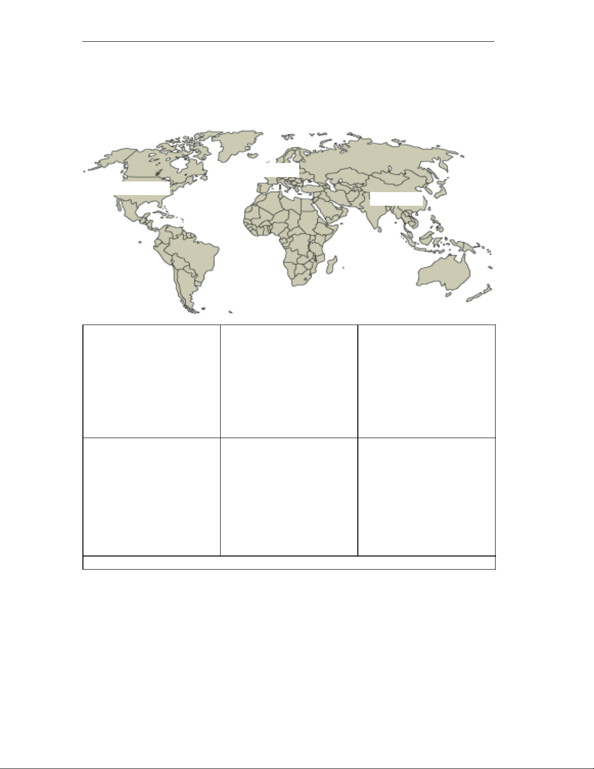
A&D Technical Support
Worldwide, available 24 hours a day:
Johnson City
Nuernberg
Beijing
Technical Support
Worldwide (Nuernberg)
Technical Support
24 hours a day, 365 days a year
Phone: +49 (180) 5050-222
Fax: +49 (180) 5050-223
E-Mail: adsupport@
GMT: +1:00
Europe / Africa (Nuernberg)
Authorization
Local time: Mon.-Fri.
8:00 AM to 5:00 PM
Phone: +49 (180) 5050–222
Fax: +49 (180) 5050-223
E-Mail: adsupport@
GMT: +1:00
The languages of the SIMATIC Hotlines and the authorization hotline are generally German and English.
siemens.com
siemens.com
United States (Johnson City)
Technical Support and
Authorization
Local time: Mon.-Fri.
8:00 AM to 500 PM
Phone: +1 (423) 262 2522
Fax: +1 (423) 262 2289
E-Mail: simatic.hotline@
sea.siemens.com
GMT: –5:00
Asia / Australia (Beijing)
Technical Support and
Authorization
Local time: Mon.-Fri.
8:00 AM to 5:00 PM
Phone: +86 10 64 75 75 75
Fax: +86 10 64 74 74 74
E-Mail: adsupport.asia@
siemens.com
GMT: +8:00
viii
S7-400, M7-400 Programmable Controllers Module Specifications
A5E00069467-07
Page 9

Service & Support on the Internet
In addition to our documentation, we offer our Know-how online on the internet at:
http://www.siemens.com/automation/service&support
where you will find the following:
• The newsletter, which constantly provides you with up–to–date information on
your products.
• The right documents via our Search function in Service & Support.
• A forum, where users and experts from all over the world exchange their
experiences.
• Your local representative for Automation & Drives via our representatives
database.
• Information on field service, repairs, spare parts and more under “Services”.
Preface
S7-400, M7-400 Programmable Controllers Module Specifications
A5E00069467-07
ix
Page 10

Preface
x
S7-400, M7-400 Programmable Controllers Module Specifications
A5E00069467-07
Page 11

Contents
1 General Technical Specifications 1-1. . . . . . . . . . . . . . . . . . . . . . . . . . . . . . . . . . . . . . . . .
1.1 Standards and Approvals 1-2. . . . . . . . . . . . . . . . . . . . . . . . . . . . . . . . . . . . . . . . .
1.2 Electromagnetic Compatibility 1-9. . . . . . . . . . . . . . . . . . . . . . . . . . . . . . . . . . . . .
1.3 Shipping and Storage Conditions for Modules and Backup Batteries 1-12. . . .
1.4 Mechanical and Ambient Climatic Conditions for Operating
the S7-400/M7-400 1-14. . . . . . . . . . . . . . . . . . . . . . . . . . . . . . . . . . . . . . . . . . . . . . .
1.5 Information on Insulation Tests, Protection Class and
Degree of Protection 1-18. . . . . . . . . . . . . . . . . . . . . . . . . . . . . . . . . . . . . . . . . . . . .
1.6 Using S7-400 in a zone 2 explosion–risk area 1-19. . . . . . . . . . . . . . . . . . . . . . .
2 Racks 2-1. . . . . . . . . . . . . . . . . . . . . . . . . . . . . . . . . . . . . . . . . . . . . . . . . . . . . . . . . . . . . . . . . .
2.1 Function and Structure of the Racks 2-2. . . . . . . . . . . . . . . . . . . . . . . . . . . . . . . .
2.2 The Racks UR1; (6ES7400-1TA01-0AA0) and
UR2; (6ES7400-1JA01-0AA0) 2-3. . . . . . . . . . . . . . . . . . . . . . . . . . . . . . . . . . . . .
2.3 The Rack UR2-H; (6ES7400-2JA00-0AA0) 2-5. . . . . . . . . . . . . . . . . . . . . . . . . .
2.4 The Rack CR2; (6ES7401-2TA01-0AA0) 2-7. . . . . . . . . . . . . . . . . . . . . . . . . . . .
2.5 The Rack CR3; (6ES7401-2TA01-0AA0) 2-8. . . . . . . . . . . . . . . . . . . . . . . . . . . .
2.6 The Racks ER1; (6ES7403-1TA01-0AA0)
and ER2; (6ES7403-1JA01-0AA0) 2-9. . . . . . . . . . . . . . . . . . . . . . . . . . . . . . . . .
3 Power Supply Modules 3-1. . . . . . . . . . . . . . . . . . . . . . . . . . . . . . . . . . . . . . . . . . . . . . . . . .
3.1 Common Characteristics of the Power Supply Modules 3-2. . . . . . . . . . . . . . .
3.2 Redundant Power Supply Modules 3-4. . . . . . . . . . . . . . . . . . . . . . . . . . . . . . . . .
3.3 Backup Battery (Option) 3-6. . . . . . . . . . . . . . . . . . . . . . . . . . . . . . . . . . . . . . . . . .
3.4 Controls and Indicators 3-8. . . . . . . . . . . . . . . . . . . . . . . . . . . . . . . . . . . . . . . . . . .
3.5 Fault/Error Messages via LEDs 3-13. . . . . . . . . . . . . . . . . . . . . . . . . . . . . . . . . . . .
3.6 Power Supply Module PS 407 4A; (6ES7407-0DA00-0AA0) 3-19. . . . . . . . . . .
3.7 Power Supply Module PS 407 4A; (6ES7407-0DA01-0AA0) 3-21. . . . . . . . . . .
3.8 Power Supply Modules
PS 407 10A; (6ES7407-0KA01-0AA0) and
PS 407 10A R; (6ES7407-0KR00-0AA0) 3-23. . . . . . . . . . . . . . . . . . . . . . . . . . . .
3.9 Power Supply Module PS 407 20A; (6ES7407-0RA00-0AA0) 3-26. . . . . . . . . .
3.10 Power Supply Module PS 407 20A; (6ES7407-0RA01-0AA0) 3-28. . . . . . . . . .
3.11 Power Supply Module PS 405 4A; (6ES7405-0DA00-0AA0) 3-30. . . . . . . . . . .
S7-400, M7-400 Programmable Controllers Module Specifications
A5E00069467-07
xi
Page 12

Contents
3.12 Power Supply Module PS 405 4A; (6ES7405-0DA01-0AA0) 3-32. . . . . . . . . . .
3.13 Power Supply Module PS 405 10A; (6ES7405-0KA00-0AA0) 3-34. . . . . . . . . .
3.14 Power Supply Modules
PS 405 10A; (6ES7405-0KA01-0AA0) and
PS 405 10A R; (405-0KR00-0AA0) 3-36. . . . . . . . . . . . . . . . . . . . . . . . . . . . . . . . .
3.15 Power Supply Module PS 405 20A; (6ES7405-0RA00-0AA0) 3-38. . . . . . . . . .
3.16 Power Supply Module PS 405 20A; (6ES7405-0RA01-0AA0) 3-40. . . . . . . . . .
4 Digital Modules 4-1. . . . . . . . . . . . . . . . . . . . . . . . . . . . . . . . . . . . . . . . . . . . . . . . . . . . . . . . .
4.1 Module Overview 4-3. . . . . . . . . . . . . . . . . . . . . . . . . . . . . . . . . . . . . . . . . . . . . . . .
4.2 Sequence of Steps from Choosing to Commissioning the Digital Module 4-5
4.3 Digital Module Parameter Assignment 4-6. . . . . . . . . . . . . . . . . . . . . . . . . . . . . .
4.3.1 Parameters of the Digital Input Modules 4-7. . . . . . . . . . . . . . . . . . . . . . . . . . . . .
4.3.2 Parameters of the Digital Output Modules 4-8. . . . . . . . . . . . . . . . . . . . . . . . . . .
4.4 Diagnostics of the Digital Modules 4-9. . . . . . . . . . . . . . . . . . . . . . . . . . . . . . . . . .
4.5 Interrupts of the Digital Modules 4-13. . . . . . . . . . . . . . . . . . . . . . . . . . . . . . . . . . . .
4.6 Input Characteristic Curve for Digital Inputs 4-15. . . . . . . . . . . . . . . . . . . . . . . . . .
4.7 Digital Input Module SM 421; DI 32 24 VDC
(6ES7421-1BL00-0AA0) 4-17. . . . . . . . . . . . . . . . . . . . . . . . . . . . . . . . . . . . . . . . . .
4.8 Digital Input Module SM 421; DI 32 24 VDC;
(6ES7421-1BL01-0AA0) 4-20. . . . . . . . . . . . . . . . . . . . . . . . . . . . . . . . . . . . . . . . . .
4.9 Digital Input Module SM 421; DI 16 24 VDC;
(6ES7421-7BH00-0AB0) 4-23. . . . . . . . . . . . . . . . . . . . . . . . . . . . . . . . . . . . . . . . . .
4.9.1 Assigning Parameters to the SM 421; DI 16 24 VDC 4-27. . . . . . . . . . . . . . .
4.9.2 Behavior of the SM 421; DI 16 24 VDC 4-29. . . . . . . . . . . . . . . . . . . . . . . . . .
4.10 Digital Input Module SM 421; DI 16 24 VDC;
(6ES7421-7BH00-0AB0) 4-32. . . . . . . . . . . . . . . . . . . . . . . . . . . . . . . . . . . . . . . . . .
4.10.1 Assigning Parameters to the SM 421; DI 16 24 VDC 4-36. . . . . . . . . . . . . . .
4.10.2 Behavior of the SM 421; DI 16 24 VDC 4-38. . . . . . . . . . . . . . . . . . . . . . . . . . . .
4.11 Digital Input Module SM 421; DI 16 120 VAC;
(6ES7421-5EH00-0AA0) 4-41. . . . . . . . . . . . . . . . . . . . . . . . . . . . . . . . . . . . . . . . . .
4.12 Digital Input Module SM 421; DI 16 24/60 VUC;
(6ES7 421-7DH00-0AB0) 4-44. . . . . . . . . . . . . . . . . . . . . . . . . . . . . . . . . . . . . . . . .
4.12.1 Assigning Parameters to the SM 421; DI 16 24/60 VUC 4-47. . . . . . . . . . . .
4.13 Digital Input Module SM 421; DI 16 120/230 VUC;
(6ES7 421-1FH00-0AA0) 4-50. . . . . . . . . . . . . . . . . . . . . . . . . . . . . . . . . . . . . . . . .
4.14 Digital Input Module SM 421; DI 16 120/230 VUC;
(6ES7421-1FH20-0AA0) 4-53. . . . . . . . . . . . . . . . . . . . . . . . . . . . . . . . . . . . . . . . . .
4.15 Digital Input Module SM 421; DI 32 120 VUC;
(6ES7421-1EL00-0AA0) 4-56. . . . . . . . . . . . . . . . . . . . . . . . . . . . . . . . . . . . . . . . . .
4.16 Digital Output Module SM 422;
DO 16 24 VDC/2 A; (6ES7422-1BH10-0AA0) 4-59. . . . . . . . . . . . . . . . . . . . .
S7-400, M7-400 Programmable Controllers Module Specifications
xii
A5E00069467-07
Page 13

Contents
4.17 Digital Output Module SM 422;
DO 16 24 VDC/2 A; (6ES7422-1BH11-0AA0) 4-62. . . . . . . . . . . . . . . . . . . . .
4.18 Digital Output Module SM 422; DO 16 0-125 VDC/1.5 A;
(6ES7422-5EH10-0AB0) 4-65. . . . . . . . . . . . . . . . . . . . . . . . . . . . . . . . . . . . . . . . . .
4.18.1 Assigning Parameters to the SM 422; DO 16 20-125 VDC/1.5 A 4-69. . . .
4.19 Digital Output Module SM 422; DO 32 24 VDC/0.5 A;
(6ES7422-1BL00-0AA0) 4-70. . . . . . . . . . . . . . . . . . . . . . . . . . . . . . . . . . . . . . . . . .
4.20 Digital Output Module SM 422; DO 32 24 VDC/0.5 A;
(6ES7422-7BL00-0AB0) 4-73. . . . . . . . . . . . . . . . . . . . . . . . . . . . . . . . . . . . . . . . . .
4.20.1 Assigning Parameters to the SM 422; DO 32 24 VDC/0.5 A 4-77. . . . . . . .
4.20.2 Behavior of the SM 422; DO 32 24 VDC/0.5 A 4-78. . . . . . . . . . . . . . . . . . . .
4.21 Digital Output Module SM 422; DO 8 120/230 VAC/5 A;
(6ES7422-1FF00-0AA0) 4-79. . . . . . . . . . . . . . . . . . . . . . . . . . . . . . . . . . . . . . . . . .
4.22 Digital Output Module SM 422; DO 16 120/230 VAC/2 A;
(6ES7422-1FH00-0AA0) 4-83. . . . . . . . . . . . . . . . . . . . . . . . . . . . . . . . . . . . . . . . . .
4.23 Digital Output Module SM 422; DO 16 20-120 VAC/2 A;
(6ES7422-5EH00-0AB0) 4-87. . . . . . . . . . . . . . . . . . . . . . . . . . . . . . . . . . . . . . . . . .
4.23.1 Assigning Parameters to the SM 422; DO 16 20-120 VAC/2 A 4-90. . . . . .
4.24 Relay Output Module SM 422; DO 16 30/230 VUC/Rel. 5 A;
(6ES7422-1HH00-0AA0) 4-91. . . . . . . . . . . . . . . . . . . . . . . . . . . . . . . . . . . . . . . . . .
5 Analog Modules 5-1. . . . . . . . . . . . . . . . . . . . . . . . . . . . . . . . . . . . . . . . . . . . . . . . . . . . . . . . .
5.1 Module Overview 5-3. . . . . . . . . . . . . . . . . . . . . . . . . . . . . . . . . . . . . . . . . . . . . . . .
5.2 Sequence of Steps from Choosing to Commissioning
the Analog Modules 5-5. . . . . . . . . . . . . . . . . . . . . . . . . . . . . . . . . . . . . . . . . . . . . .
5.3 Analog Value Representation 5-6. . . . . . . . . . . . . . . . . . . . . . . . . . . . . . . . . . . . . .
5.3.1 Analog Value Representation for Analog Input Channels 5-7. . . . . . . . . . . . . .
5.3.2 Analog Value Representation for Analog Output Channels 5-22. . . . . . . . . . . . .
5.4 Setting the Measuring Method and Measuring Ranges
of the Analog Input Channels 5-27. . . . . . . . . . . . . . . . . . . . . . . . . . . . . . . . . . . . . .
5.5 Behavior of the Analog Modules 5-30. . . . . . . . . . . . . . . . . . . . . . . . . . . . . . . . . . .
5.5.1 Effect of Supply Voltage and Operating Mode 5-30. . . . . . . . . . . . . . . . . . . . . . . .
5.5.2 Effect of Range of Values of the Analog Values 5-31. . . . . . . . . . . . . . . . . . . . . .
5.5.3 Effect of Operational Limit and Basic Error Limit 5-32. . . . . . . . . . . . . . . . . . . . . .
5.6 Conversion, Cycle, Setting and Response Time of Analog Modules 5-34. . . . .
5.7 Analog Module Parameter Assignment 5-38. . . . . . . . . . . . . . . . . . . . . . . . . . . . . .
5.7.1 Parameters of the Analog Input Modules 5-39. . . . . . . . . . . . . . . . . . . . . . . . . . . .
5.7.2 Parameters of the Analog Output Modules 5-41. . . . . . . . . . . . . . . . . . . . . . . . . .
5.8 Connecting Sensors to Analog Inputs 5-42. . . . . . . . . . . . . . . . . . . . . . . . . . . . . . .
5.9 Connecting Voltage Sensors 5-45. . . . . . . . . . . . . . . . . . . . . . . . . . . . . . . . . . . . . . .
5.10 Connecting Current Sensors 5-46. . . . . . . . . . . . . . . . . . . . . . . . . . . . . . . . . . . . . . .
5.11 Connecting Resistance Thermometers and Resistors 5-49. . . . . . . . . . . . . . . . .
5.12 Connecting Thermocouples 5-52. . . . . . . . . . . . . . . . . . . . . . . . . . . . . . . . . . . . . . .
S7-400, M7-400 Programmable Controllers Module Specifications
A5E00069467-07
xiii
Page 14

Contents
5.13 Connecting Loads/Actuators to Analog Outputs 5-58. . . . . . . . . . . . . . . . . . . . . .
5.14 Connecting Loads/Actuators to Voltage Outputs 5-59. . . . . . . . . . . . . . . . . . . . . .
5.15 Connecting Loads/Actuators to Current Outputs 5-61. . . . . . . . . . . . . . . . . . . . . .
5.16 Diagnostics of the Analog Modules 5-62. . . . . . . . . . . . . . . . . . . . . . . . . . . . . . . . .
5.17 Analog Module Interrupts 5-66. . . . . . . . . . . . . . . . . . . . . . . . . . . . . . . . . . . . . . . . .
5.18 Analog Input Module SM 431; AI 8 13 Bit; (6ES7431-1KF00-0AB0) 5-69. .
5.18.1 Commissioning the SM 431; AI 8 13 Bit 5-73. . . . . . . . . . . . . . . . . . . . . . . . . .
5.18.2 Measuring Methods and Measuring Ranges of the SM 431; AI 8 13 Bit 5-74.
5.19 Analog Input Module SM 431; AI 8 14 Bit; (6ES7 431-1KF10-0AB0) 5-76.
5.19.1 Commissioning the SM 431; AI 8 14 Bit 5-82. . . . . . . . . . . . . . . . . . . . . . . . . .
5.19.2 Measuring Methods and Measuring Ranges of the SM 431; AI 8 14 Bit 5-84.
5.20 Analog Input Module SM 431; AI 8 4 Bit; (6ES7431-1KF20-0AB0) 5-89. . .
5.20.1 Commissioning the SM 431; AI 8 14 Bit 5-93. . . . . . . . . . . . . . . . . . . . . . . . . .
5.20.2 Measuring Methods and Measuring Ranges
of the SM 431; AI 8 14 Bit 5-95. . . . . . . . . . . . . . . . . . . . . . . . . . . . . . . . . . . . . .
5.21 Analog Input Module SM 431; AI 16 13 Bit; (6ES7431-0HH00-0AB0) 5-98
5.21.1 Commissioning the SM 431; AI 16 13 Bit 5-103. . . . . . . . . . . . . . . . . . . . . . . . .
5.21.2 Measuring Methods and Measuring Ranges
of the SM 431; AI 16 13 Bit 5-104. . . . . . . . . . . . . . . . . . . . . . . . . . . . . . . . . . . . .
5.22 Analog Input Module SM 431; AI 16 16 Bit; (6ES7431-7QH00-0AB0) 5-106
5.22.1 Commissioning the SM 431; AI 16 16 Bit 5-114. . . . . . . . . . . . . . . . . . . . . . . . .
5.22.2 Measuring Methods and Measuring Ranges
of the SM 431; AI 16 16 Bit 5-117. . . . . . . . . . . . . . . . . . . . . . . . . . . . . . . . . . . . .
5.23 Analog Input Module SM 431; AI 8 RTD 16 Bit;
(6ES7 431-7KF10-0AB0) 5-122. . . . . . . . . . . . . . . . . . . . . . . . . . . . . . . . . . . . . . . . . .
5.23.1 Commissioning the SM 431; AI 8 RTD 16 Bit 5-126. . . . . . . . . . . . . . . . . .
5.23.2 Measuring Methods and Measuring Ranges
of the SM 431; AI 8 RTD 16 Bit 5-129. . . . . . . . . . . . . . . . . . . . . . . . . . . . . .
5.24 Analog Input Module SM 431; AI 8 16 Bit;
(6ES7431-7KF00-0AB0) 5-130. . . . . . . . . . . . . . . . . . . . . . . . . . . . . . . . . . . . . . . . . .
5.24.1 Commissioning the SM 431; AI 8 16 Bit 5-135. . . . . . . . . . . . . . . . . . . . . . . . . .
5.24.2 Measuring Methods and Measuring Ranges of the SM 431;
AI 8 16 Bit 5-139. . . . . . . . . . . . . . . . . . . . . . . . . . . . . . . . . . . . . . . . . . . . . . . . . . .
5.25 Analog Output Module SM 432; AO 8 13 Bit;
(6ES7432-1HF00-0AB0) 5-141. . . . . . . . . . . . . . . . . . . . . . . . . . . . . . . . . . . . . . . . . .
5.25.1 Commissioning the SM 432; AO 8 13 Bit 5-145. . . . . . . . . . . . . . . . . . . . . . . . .
5.25.2 Output Ranges of the Analog Output Module SM 432;
AO 8 13 Bit 5-145. . . . . . . . . . . . . . . . . . . . . . . . . . . . . . . . . . . . . . . . . . . . . . . . . .
xiv
S7-400, M7-400 Programmable Controllers Module Specifications
A5E00069467-07
Page 15

Contents
6 Interface Modules 6-1. . . . . . . . . . . . . . . . . . . . . . . . . . . . . . . . . . . . . . . . . . . . . . . . . . . . . . .
6.1 Common Features of the Interface Modules 6-2. . . . . . . . . . . . . . . . . . . . . . . . .
6.2 The Interface Modules
IM 460-0; (6ES7460-0AA00-0AB0, 6ES7460-0AA01-0AB0)
and IM 461-0; (6ES7461-0AA00-0AA0, 6ES7461-0AA01-0AA0) 6-7. . . . . . .
6.3 The Interface Modules
IM 460-1; (6ES7460-1BA00-0AB0, 6ES7460-1BA01-0AB0)
and IM 461-1; (6ES7461-1BA00-0AA0, 6ES7461-1BA01-0AA0) 6-10. . . . . . .
6.4 The Interface Modules
IM 460-3; (6ES7460-3AA00-0AB0, 6ES7460-3AA01-0AB0)
and IM 461-3; (6ES7461-3AA00-0AA0, 6ES7461-3AA01-0AA0) 6-14. . . . . . .
6.5 The Interface Modules
IM 460-4; (6ES7460-4AA01-0AB0) and
IM 461-4; (6ES7461-4AA01-0AA0) 6-18. . . . . . . . . . . . . . . . . . . . . . . . . . . . . . . . .
7 IM 463-2 7-1. . . . . . . . . . . . . . . . . . . . . . . . . . . . . . . . . . . . . . . . . . . . . . . . . . . . . . . . . . . . . . . .
7.1 Using SIMATIC S5 Expansion Units in an S7-400 7-2. . . . . . . . . . . . . . . . . . . .
7.2 Rules for Connecting S5 Expansion Units 7-3. . . . . . . . . . . . . . . . . . . . . . . . . . .
7.3 Operator Controls and Indicators 7-4. . . . . . . . . . . . . . . . . . . . . . . . . . . . . . . . . . .
7.4 Installing and Connecting the IM 463-2 7-6. . . . . . . . . . . . . . . . . . . . . . . . . . . . .
7.5 Setting the Operating Modes of the IM 314 7-8. . . . . . . . . . . . . . . . . . . . . . . . . .
7.6 Configuring S5 Modules for Operation in the S7-400 7-10. . . . . . . . . . . . . . . . . .
7.7 Pin Assignments of the 721 Connecting Cable 7-11. . . . . . . . . . . . . . . . . . . . . . .
7.8 Terminating Connector for IM 314 7-13. . . . . . . . . . . . . . . . . . . . . . . . . . . . . . . . . .
7.9 Technical Specifications (6ES7463–2AA00–0AA0) 7-14. . . . . . . . . . . . . . . . . . .
8 PROFIBUS DP Master Interface IM 467/IM 467 FO 8-1. . . . . . . . . . . . . . . . . . . . . . . . . .
8.1 PROFIBUS DP Master Interface IM 467/IM 467 FO 8-2. . . . . . . . . . . . . . . . . .
8.1.1 Indicators and the Mode Selector 8-4. . . . . . . . . . . . . . . . . . . . . . . . . . . . . . . . . .
8.2 Configuration 8-6. . . . . . . . . . . . . . . . . . . . . . . . . . . . . . . . . . . . . . . . . . . . . . . . . . . .
8.3 Connection to PROFIBUS DP 8-8. . . . . . . . . . . . . . . . . . . . . . . . . . . . . . . . . . . . .
8.3.1 Bus Connector 8-8. . . . . . . . . . . . . . . . . . . . . . . . . . . . . . . . . . . . . . . . . . . . . . . . . . .
8.3.2 Optical Connection to PROFIBUS DP 8-9. . . . . . . . . . . . . . . . . . . . . . . . . . . . . . .
8.3.3 Connecting a Fiber-Optic Cable to the IM 467 FO 8-10. . . . . . . . . . . . . . . . . . . .
8.4 Technical Specifications 8-12. . . . . . . . . . . . . . . . . . . . . . . . . . . . . . . . . . . . . . . . . . .
8.4.1 Technical Specifications of the IM 467 8-12. . . . . . . . . . . . . . . . . . . . . . . . . . . . . .
8.4.2 Technical Specifications of the IM 467 FO 8-13. . . . . . . . . . . . . . . . . . . . . . . . . . .
9 Cable Duct and Fan Subassemblies 9-1. . . . . . . . . . . . . . . . . . . . . . . . . . . . . . . . . . . . . .
9.1 Fan Monitoring in the Fan Subassemblies 9-2. . . . . . . . . . . . . . . . . . . . . . . . . . .
9.2 Cable Duct; (6ES7408-0TA00-0AA0) 9-4. . . . . . . . . . . . . . . . . . . . . . . . . . . . . . .
9.3 The 120/230 VAC Fan Subassembly; (6ES7408-1TB00-0XA0) 9-5. . . . . . . . .
9.4 The 24 VDC Fan Subassembly; (6ES7408-1TA00-0XA0) 9-7. . . . . . . . . . . . . .
S7-400, M7-400 Programmable Controllers Module Specifications
A5E00069467-07
xv
Page 16

Contents
10 RS 485 Repeater 10-1. . . . . . . . . . . . . . . . . . . . . . . . . . . . . . . . . . . . . . . . . . . . . . . . . . . . . . . . .
10.1 Application and Characteristics (6ES7972-0AA01-0XA0) 10-2. . . . . . . . . . . . . .
10.2 Appearance of the RS 485 Repeater; (6ES7972-0AA01-0XA0) 10-3. . . . . . . .
10.3 RS 485 Repeater in Ungrounded and Grounded Operation 10-4. . . . . . . . . . . .
10.4 Technical Specifications 10-6. . . . . . . . . . . . . . . . . . . . . . . . . . . . . . . . . . . . . . . . . . .
11 CPUs for M7-400 11-1. . . . . . . . . . . . . . . . . . . . . . . . . . . . . . . . . . . . . . . . . . . . . . . . . . . . . . . .
11.1 Performance Features 11-2. . . . . . . . . . . . . . . . . . . . . . . . . . . . . . . . . . . . . . . . .
11.2 Technical Specifications 11-3. . . . . . . . . . . . . . . . . . . . . . . . . . . . . . . . . . . . . . . . . . .
11.3 Function Elements 11-4. . . . . . . . . . . . . . . . . . . . . . . . . . . . . . . . . . . . . . . . . . . . . . .
11.3.1 Status and Fault LEDs 11-6. . . . . . . . . . . . . . . . . . . . . . . . . . . . . . . . . . . . . . . . . . . .
11.3.2 Memory Cards 11-8. . . . . . . . . . . . . . . . . . . . . . . . . . . . . . . . . . . . . . . . . . . . . . . . . . .
11.3.3 Mode Selector Switch 11-9. . . . . . . . . . . . . . . . . . . . . . . . . . . . . . . . . . . . . . . . . . . .
11.3.4 Submodule Receptacles for Interface Submodules 11-11. . . . . . . . . . . . . . . . . . .
11.3.5 Memory Submodules Suitable for the Main Memory 11-13. . . . . . . . . . . . . . . . . .
11.3.6 Expansion Socket 11-14. . . . . . . . . . . . . . . . . . . . . . . . . . . . . . . . . . . . . . . . . . . . . . . .
11.3.7 Multipoint Interface (MPI) 11-15. . . . . . . . . . . . . . . . . . . . . . . . . . . . . . . . . . . . . . . . .
11.4 The BIOS Setup 11-16. . . . . . . . . . . . . . . . . . . . . . . . . . . . . . . . . . . . . . . . . . . . . . . . .
11.4.1 BIOS Power Up 11-17. . . . . . . . . . . . . . . . . . . . . . . . . . . . . . . . . . . . . . . . . . . . . . . . . .
11.4.2 BIOS Hot Keys 11-19. . . . . . . . . . . . . . . . . . . . . . . . . . . . . . . . . . . . . . . . . . . . . . . . . .
11.4.3 Operator Inputs in the BIOS Setup 11-20. . . . . . . . . . . . . . . . . . . . . . . . . . . . . . . . .
11.4.4 Opening and Exiting the BIOS Setup 11-23. . . . . . . . . . . . . . . . . . . . . . . . . . . . . . .
11.4.5 Setup Page “User Help” 11-25. . . . . . . . . . . . . . . . . . . . . . . . . . . . . . . . . . . . . . . . . . .
11.4.6 Setup Page “IF modules” 11-26. . . . . . . . . . . . . . . . . . . . . . . . . . . . . . . . . . . . . . . . . .
11.4.7 Setup Page “Timeout Function” 11-30. . . . . . . . . . . . . . . . . . . . . . . . . . . . . . . . . . . .
11.4.8 Setup Page “Security” 11-31. . . . . . . . . . . . . . . . . . . . . . . . . . . . . . . . . . . . . . . . . . . .
11.4.9 Setup Page “Date and Time” 11-33. . . . . . . . . . . . . . . . . . . . . . . . . . . . . . . . . . . . . .
11.4.10 “Hard Disk” Setup Page 11-34. . . . . . . . . . . . . . . . . . . . . . . . . . . . . . . . . . . . . . . . . . .
11.4.11 Setup Page “Floppy/Card” 11-36. . . . . . . . . . . . . . . . . . . . . . . . . . . . . . . . . . . . . . . . .
11.4.12 Setup Page “Boot Options” 11-37. . . . . . . . . . . . . . . . . . . . . . . . . . . . . . . . . . . . . . . .
11.4.13 Setup Page “System” 11-39. . . . . . . . . . . . . . . . . . . . . . . . . . . . . . . . . . . . . . . . . . . . .
11.5 I/O Addresses, Main Memory and Interrupt Assignments 11-41. . . . . . . . . . . . . .
12 M7-400 Expansions 12-1. . . . . . . . . . . . . . . . . . . . . . . . . . . . . . . . . . . . . . . . . . . . . . . . . . . . . .
12.1 Overview 12-2. . . . . . . . . . . . . . . . . . . . . . . . . . . . . . . . . . . . . . . . . . . . . . . . . . . . . . .
12.2 EXM 478 Expansion Module; (6ES7 478-2AC00-0AC0) 12-6. . . . . . . . . . . . . . .
12.2.1 Addressing the EXM 478 Expansion Module 12-7. . . . . . . . . . . . . . . . . . . . . . . . .
12.2.2 Interrupt Assignments, Signal Switching EXM 478 12-13. . . . . . . . . . . . . . . . . . . .
12.2.3 Technical Specifications of the EXM 478 Expansion Module 12-14. . . . . . . . . . .
12.3 ATM 478 AT Adapter Module; (6ES7 478-2CA00-0AC0) 12-15. . . . . . . . . . . . . .
12.3.1 Pin Assignments of the AT Module 12-16. . . . . . . . . . . . . . . . . . . . . . . . . . . . . . . . .
12.3.2 Technical Specifications of the ATM 478 AT Adapter Module 12-19. . . . . . . . . . .
12.4 MSM 478 Mass Storage Module; (6ES7 478-2BA00-0AC0) 12-22. . . . . . . . . . . .
12.4.1 LPT1 Parallel Port 12-23. . . . . . . . . . . . . . . . . . . . . . . . . . . . . . . . . . . . . . . . . . . . . . . .
12.4.2 Technical Specifications of the MSM 478 Mass Storage Module 12-25. . . . . . . .
S7-400, M7-400 Programmable Controllers Module Specifications
xvi
A5E00069467-07
Page 17

Contents
13 Interface Submodules 13-1. . . . . . . . . . . . . . . . . . . . . . . . . . . . . . . . . . . . . . . . . . . . . . . . . . .
13.1 Interface Submodules Overview 13-2. . . . . . . . . . . . . . . . . . . . . . . . . . . . . . . . . . .
13.2 Submodule IDs and Insertion Rules 13-4. . . . . . . . . . . . . . . . . . . . . . . . . . . . . . . .
13.3 IF 962-VGA Interface Submodule for M7-300/400;
(6ES7962-1BA00-0AC0) 13-5. . . . . . . . . . . . . . . . . . . . . . . . . . . . . . . . . . . . . . . . . .
13.3.1 Pin Assignments 13-6. . . . . . . . . . . . . . . . . . . . . . . . . . . . . . . . . . . . . . . . . . . . . . . . .
13.3.2 Addressing, Interrupts, and Submodule ID 13-7. . . . . . . . . . . . . . . . . . . . . . . . . .
13.3.3 Technical Specifications 13-8. . . . . . . . . . . . . . . . . . . . . . . . . . . . . . . . . . . . . . . . . . .
13.4 IF 962-COM Interface Submodule for M7-300/400;
(6ES7962-3AA00-0AC0) 13-10. . . . . . . . . . . . . . . . . . . . . . . . . . . . . . . . . . . . . . . . . .
13.4.1 Pin Assignments 13-11. . . . . . . . . . . . . . . . . . . . . . . . . . . . . . . . . . . . . . . . . . . . . . . . .
13.4.2 Addressing and Interrupts 13-12. . . . . . . . . . . . . . . . . . . . . . . . . . . . . . . . . . . . . . . . .
13.4.3 Technical Specifications 13-15. . . . . . . . . . . . . . . . . . . . . . . . . . . . . . . . . . . . . . . . . . .
13.5 IF 962-LPT Interface Submodule for M7-300/400;
(6ES7962-4AA00-0AC0) 13-16. . . . . . . . . . . . . . . . . . . . . . . . . . . . . . . . . . . . . . . . . .
13.5.1 Pin Assignments 13-17. . . . . . . . . . . . . . . . . . . . . . . . . . . . . . . . . . . . . . . . . . . . . . . . .
13.5.2 Addressing and Interrupts 13-18. . . . . . . . . . . . . . . . . . . . . . . . . . . . . . . . . . . . . . . . .
13.5.3 Technical Specifications 13-22. . . . . . . . . . . . . . . . . . . . . . . . . . . . . . . . . . . . . . . . . . .
13.6 IF 961-DIO Interface Submodule for M7-300/400;
(6ES7961-1AA00-0AC0) 13-23. . . . . . . . . . . . . . . . . . . . . . . . . . . . . . . . . . . . . . . . . .
13.6.1 Pin Assignments 13-24. . . . . . . . . . . . . . . . . . . . . . . . . . . . . . . . . . . . . . . . . . . . . . . . .
13.6.2 Addressing and Interrupts 13-26. . . . . . . . . . . . . . . . . . . . . . . . . . . . . . . . . . . . . . . . .
13.6.3 Technical Specifications 13-31. . . . . . . . . . . . . . . . . . . . . . . . . . . . . . . . . . . . . . . . . . .
13.7 IF 961-AIO Interface Submodule for M7-300/400;
(6ES7961-2AA00-0AC0) 13-33. . . . . . . . . . . . . . . . . . . . . . . . . . . . . . . . . . . . . . . . . .
13.7.1 Pin Assignments and Terminal Connection Diagram 13-34. . . . . . . . . . . . . . . . . .
13.7.2 Connecting Measured Value Sensors to Analog Inputs 13-37. . . . . . . . . . . . . . . .
13.7.3 Connecting Loads/Actuators to Analog Outputs 13-42. . . . . . . . . . . . . . . . . . . . . .
13.7.4 Conversion Time and Cycle Time of the Analog Input Channels 13-44. . . . . . . .
13.7.5 Conversion Time, Cycle Time, Settling Time,
and Response Time of the Analog Output Channels 13-45. . . . . . . . . . . . . . . . . .
13.7.6 Starting Up the IF 961-AIO Interface Submodule 13-46. . . . . . . . . . . . . . . . . . . . .
13.7.7 Addressing 13-46. . . . . . . . . . . . . . . . . . . . . . . . . . . . . . . . . . . . . . . . . . . . . . . . . . . . . .
13.7.8 Analog Output Function 13-47. . . . . . . . . . . . . . . . . . . . . . . . . . . . . . . . . . . . . . . . . . .
13.7.9 Analog Input Function 13-48. . . . . . . . . . . . . . . . . . . . . . . . . . . . . . . . . . . . . . . . . . . .
13.7.10 Analog Value Representation for the Measuring Ranges
of the Analog Inputs 13-51. . . . . . . . . . . . . . . . . . . . . . . . . . . . . . . . . . . . . . . . . . . . . .
13.7.11 Analog Value Representation for the Measuring Ranges
of the Analog Outputs 13-52. . . . . . . . . . . . . . . . . . . . . . . . . . . . . . . . . . . . . . . . . . . .
13.7.12 Diagnostics, Interrupts, and Submodule ID 13-53. . . . . . . . . . . . . . . . . . . . . . . . . .
13.7.13 Technical Specifications 13-54. . . . . . . . . . . . . . . . . . . . . . . . . . . . . . . . . . . . . . . . . . .
13.8 IF 961-CT1 Interface Submodule for M7-300/400;
(6ES7961-3AA00-0AC0) 13-56. . . . . . . . . . . . . . . . . . . . . . . . . . . . . . . . . . . . . . . . . .
13.8.1 What Can the IF961-CT1 Interface Submodule Do? 13-57. . . . . . . . . . . . . . . . . .
13.8.2 Addressing and Interrupts 13-59. . . . . . . . . . . . . . . . . . . . . . . . . . . . . . . . . . . . . . . . .
13.8.3 Technical Specifications 13-60. . . . . . . . . . . . . . . . . . . . . . . . . . . . . . . . . . . . . . . . . . .
S7-400, M7-400 Programmable Controllers Module Specifications
A5E00069467-07
xvii
Page 18

Contents
13.9 IF 964-DP Interface Submodule for S7-400 and M7-400 13-61. . . . . . . . . . . . . .
13.9.1 Pin Assignments 13-63. . . . . . . . . . . . . . . . . . . . . . . . . . . . . . . . . . . . . . . . . . . . . . . . .
13.9.2 Addressing and Interrupts 13-64. . . . . . . . . . . . . . . . . . . . . . . . . . . . . . . . . . . . . . . . .
13.9.3 Technical Specifications 13-65. . . . . . . . . . . . . . . . . . . . . . . . . . . . . . . . . . . . . . . . . . .
A Parameter Sets for Signal Modules A-1. . . . . . . . . . . . . . . . . . . . . . . . . . . . . . . . . . . . . . .
A.1 How to Assign the Parameters for Signal Modules in the User Program A-2.
A.2 Parameters of the Digital Input Modules A-4. . . . . . . . . . . . . . . . . . . . . . . . . . . . .
A.3 Parameters of the Digital Output Modules A-7. . . . . . . . . . . . . . . . . . . . . . . . . . .
A.4 Parameters of the Analog Input Modules A-10. . . . . . . . . . . . . . . . . . . . . . . . . . . .
B Diagnostic Data of the Signal Modules B-1. . . . . . . . . . . . . . . . . . . . . . . . . . . . . . . . . . . .
B.1 Evaluating the Diagnostic Data of the Signal Modules
in the User Program B-2. . . . . . . . . . . . . . . . . . . . . . . . . . . . . . . . . . . . . . . . . . . . . .
B.2 Structure and Contents of
Diagnostic Data Bytes 0 and 1 B-3. . . . . . . . . . . . . . . . . . . . . . . . . . . . . . . . . . . . .
B.3 Diagnostic Data of the Digital Input Modules
as of Byte 2 B-4. . . . . . . . . . . . . . . . . . . . . . . . . . . . . . . . . . . . . . . . . . . . . . . . . . . . .
B.4 Diagnostic Data of the Digital Output Modules
as of Byte 2 B-8. . . . . . . . . . . . . . . . . . . . . . . . . . . . . . . . . . . . . . . . . . . . . . . . . . . . .
B.5 Diagnostic Data of the Analog Input Modules
as of Byte 2 B-14. . . . . . . . . . . . . . . . . . . . . . . . . . . . . . . . . . . . . . . . . . . . . . . . . . . . .
C Spare Parts and Accessories C-1. . . . . . . . . . . . . . . . . . . . . . . . . . . . . . . . . . . . . . . . . . . . .
D Guidelines for Handling Electrostatic Sensitive Devices (ESD) D-1. . . . . . . . . . . . . .
D.1 What is ESD? D-2. . . . . . . . . . . . . . . . . . . . . . . . . . . . . . . . . . . . . . . . . . . . . . . . . . .
D.2 Electrostatic Charging of Persons D-3. . . . . . . . . . . . . . . . . . . . . . . . . . . . . . . . . .
D.3 General Protective Measures Against Electrostatic Discharge Damage D-4.
E List of Abbreviations E-1. . . . . . . . . . . . . . . . . . . . . . . . . . . . . . . . . . . . . . . . . . . . . . . . . . . .
Glossary Glossary-1. . . . . . . . . . . . . . . . . . . . . . . . . . . . . . . . . . . . . . . . . . . . . . . . . . . . .
Index Index-1. . . . . . . . . . . . . . . . . . . . . . . . . . . . . . . . . . . . . . . . . . . . . . . . . . . . . . . .
xviii
S7-400, M7-400 Programmable Controllers Module Specifications
A5E00069467-07
Page 19

Figures
1-1 Power supply to the backup battery 1-6. . . . . . . . . . . . . . . . . . . . . . . . . . . . . . . . .
2-1 Structure of a Rack with 18 Slots 2-2. . . . . . . . . . . . . . . . . . . . . . . . . . . . . . . . . . .
2-2 Dimensions of the UR1 18-Slot or UR2 9-Slot Rack 2-3. . . . . . . . . . . . . . . . . .
2-3 Rack Dimensions 2-5. . . . . . . . . . . . . . . . . . . . . . . . . . . . . . . . . . . . . . . . . . . . . . . .
2-4 CR2 Rack 2-7. . . . . . . . . . . . . . . . . . . . . . . . . . . . . . . . . . . . . . . . . . . . . . . . . . . . . . .
2-5 CR3 Rack 2-8. . . . . . . . . . . . . . . . . . . . . . . . . . . . . . . . . . . . . . . . . . . . . . . . . . . . . . .
2-6 ER1 Rack with 18 Slots and ER2 Rack with 9 Slots 2-10. . . . . . . . . . . . . . . . . . .
3-1 Controls and Indicators on the PS 407 20A Power Supply Module 3-8. . . . . .
3-2 Controls and Indicators of the PS 407 4A 3-19. . . . . . . . . . . . . . . . . . . . . . . . . . .
3-3 Controls and Indicators of the PS 407 4 A 3-21. . . . . . . . . . . . . . . . . . . . . . . . . . .
3-4 Controls and Displays of the PS 407 10A and PS 407 10A R 3-23. . . . . . . . . .
3-5 Controls and Displays of the PS 407 20A 3-25. . . . . . . . . . . . . . . . . . . . . . . . . . . .
3-6 Controls and Indicators of the PS 407 20 A 3-27. . . . . . . . . . . . . . . . . . . . . . . . . .
3-7 Controls and Indicators of the PS 405 4 A 3-29. . . . . . . . . . . . . . . . . . . . . . . . . . .
3-8 Controls and Indicators of the PS 405 4 A 3-31. . . . . . . . . . . . . . . . . . . . . . . . . . .
3-9 Controls and Indicators of the PS 405 10 A 3-33. . . . . . . . . . . . . . . . . . . . . . . . . .
3-10 Controls and Displays of the PS 405 10A and PS 405 10A R 3-35. . . . . . . . . .
3-11 Controls and Indicators of the PS 405 20 A 3-37. . . . . . . . . . . . . . . . . . . . . . . . . .
3-12 Controls and Indicators of the PS 405 20 A 3-39. . . . . . . . . . . . . . . . . . . . . . . . . .
4-1 Input Characteristic Curve for Digital Inputs 4-16. . . . . . . . . . . . . . . . . . . . . . . . . .
4-2 Terminal Assignment and Block Diagram of the SM 421; DI 32 x 24 VDC 4-18
4-3 Terminal Assignment and Block Diagram of the SM 421; DI 32 x 24 VDC 4-21
4-4 Terminal Assignment and Block Diagram of the SM 421; DI 16 x 24 VDC 4-24
4-5 Terminal Assignment Diagram for the Redundant Supply
of Sensors of the
SM 421; DI 16 x 24 VDC 4-25. . . . . . . . . . . . . . . . . . . . . . . . . . . . . . . . . . . . . . . . . .
4-6 Terminal Assignment and Block Diagram of the SM 421;
DI 16 x 24 VDC 4-33. . . . . . . . . . . . . . . . . . . . . . . . . . . . . . . . . . . . . . . . . . . . . . . . . .
4-7 Terminal Assignment Diagram for the Redundant Supply
of Sensors of the
SM 421; DI 16 x 24 VDC 4-34. . . . . . . . . . . . . . . . . . . . . . . . . . . . . . . . . . . . . . . . . .
4-8 Terminal Assignment Diagram of the SM 421; DI 16 120 VDC 4-42. . . . . . . .
4-9 Terminal Assignment and Block Diagram of the SM 421;
DI 16 x 24/60 VUC 4-45. . . . . . . . . . . . . . . . . . . . . . . . . . . . . . . . . . . . . . . . . . . . . . .
4-10 Circuit as for Active High or Active Low Input 4-49. . . . . . . . . . . . . . . . . . . . . . . .
4-11 Terminal Assignment and Block Diagram of the SM 421;
DI 16 x 120/230 VUC 4-51. . . . . . . . . . . . . . . . . . . . . . . . . . . . . . . . . . . . . . . . . . . . .
4-12 Terminal Assignment and Block Diagram of the SM 421;
DI 16 x 120/230 VUC 4-54. . . . . . . . . . . . . . . . . . . . . . . . . . . . . . . . . . . . . . . . . . . . .
4-13 Terminal Assignment and Block Diagram of the SM 421;
DI 32 x 120 VUC 4-57. . . . . . . . . . . . . . . . . . . . . . . . . . . . . . . . . . . . . . . . . . . . . . . . .
4-14 Terminal Assignment and Block Diagram of the SM 422;
DO 16 x 24 VDC/2 A 4-60. . . . . . . . . . . . . . . . . . . . . . . . . . . . . . . . . . . . . . . . . . . . .
4-15 Terminal Assignment and Block Diagram of the SM 422;
DO 16 x 24 VDC/2 A 4-63. . . . . . . . . . . . . . . . . . . . . . . . . . . . . . . . . . . . . . . . . . . . .
4-16 Terminal Assignment Diagram of the SM 422;
DO 16 x 20-125 VDC/1.5 A 4-66. . . . . . . . . . . . . . . . . . . . . . . . . . . . . . . . . . . . . . . .
4-17 Terminal Assignment and Block Diagram of the SM 422;
DO 32 x 24 VDC/0.5 A 4-71. . . . . . . . . . . . . . . . . . . . . . . . . . . . . . . . . . . . . . . . . . . .
4-18 Terminal Assignment and Block Diagram of the SM 422;
DO 32 x 24 VDC/0.5 A 4-74. . . . . . . . . . . . . . . . . . . . . . . . . . . . . . . . . . . . . . . . . . . .
Contents
S7-400, M7-400 Programmable Controllers Module Specifications
A5E00069467-07
xix
Page 20

Contents
4-19 Terminal Assignment and Block Diagram of the SM 422;
DO 8 x 120/230 VAC/5 A 4-80. . . . . . . . . . . . . . . . . . . . . . . . . . . . . . . . . . . . . . . . . .
4-20 Terminal Assignment and Block Diagram of the SM 422;
DO 16 x 120/230 VAC/2 A 4-84. . . . . . . . . . . . . . . . . . . . . . . . . . . . . . . . . . . . . . . . .
4-21 Terminal Assignment Diagram of the SM 422;
DO 16 x 20-120 VAC/2 A 4-88. . . . . . . . . . . . . . . . . . . . . . . . . . . . . . . . . . . . . . . . . .
4-22 Terminal Assignment and Block Diagram of the SM 422;
DO 16 x 30/230 VUC/Rel. 5 A 4-92. . . . . . . . . . . . . . . . . . . . . . . . . . . . . . . . . . . . .
5-1 Levering the Measuring Range Module out of the Analog Input Module 5-29.
5-2 Inserting the Measuring Range Module into the Analog Input Module 5-30. . .
5-3 Example of the Relative Error of an Analog Output Module 5-34. . . . . . . . . . . .
5-4 Scan Time of an Analog Input or Output Module 5-35. . . . . . . . . . . . . . . . . . . . .
5-5 Example of the Influence of Smoothing on the Step Response 5-37. . . . . . . . .
5-6 Settling and Response Times of the Analog Output Channels 5-38. . . . . . . . . .
5-7 Connecting Isolated Sensors to an Isolated AI 5-44. . . . . . . . . . . . . . . . . . . . . . .
5-8 Connecting Non-Isolated Sensors to an Isolated AI 5-45. . . . . . . . . . . . . . . . . . .
5-9 Connecting Voltage Sensors to an AI 5-46. . . . . . . . . . . . . . . . . . . . . . . . . . . . . . .
5-10 Connecting Two-Wire Transmitters to an Isolated AI 5-48. . . . . . . . . . . . . . . . . .
5-11 Connecting Two-Wire Transmitters to an SM 431; 8 x 13 Bit 5-48. . . . . . . . . . .
5-12 Connecting Four-Wire Transmitters to an AI 5-49. . . . . . . . . . . . . . . . . . . . . . . . .
5-13 Connecting Four-Wire Transmitters to an SM 431; 8 x 13 Bit 5-49. . . . . . . . . . .
5-14 Four-Conductor Connection of Resistance Thermometers on an AI 5-51. . . . .
5-15 Three-Wire Connection of Resistance Thermometers to an AI 5-52. . . . . . . . .
5-16 Two-Wire Connection of Resistance Thermometers to an AI 5-52. . . . . . . . . . .
5-17 Design of Thermocouples 5-53. . . . . . . . . . . . . . . . . . . . . . . . . . . . . . . . . . . . . . . . .
5-18 Connection of Thermocouples without Compensation
or Using the Reference Temperature Value to an Isolated AI 5-56. . . . . . . . . . .
5-19 Connection of a Thermocouple with Reference Junction (Order No.
M72166-xxx00) to an Isolated AI 5-57. . . . . . . . . . . . . . . . . . . . . . . . . . . . . . . . . . .
5-20 Connection of Thermocouples of the Same Type
with External Compensation by Means of a Resistance Thermometer,
Connected to Channel 0 5-58. . . . . . . . . . . . . . . . . . . . . . . . . . . . . . . . . . . . . . . . . .
5-21 Connecting Loads to a Voltage Output of an Isolated AO
over a Four-Conductor Connection 5-61. . . . . . . . . . . . . . . . . . . . . . . . . . . . . . . . .
5-22 Two-Conductor Connection of Loads to a Voltage Output
of an Isolated AO 5-61. . . . . . . . . . . . . . . . . . . . . . . . . . . . . . . . . . . . . . . . . . . . . . . .
5-23 Connecting Loads to a Current Output of an Isolated AO 5-62. . . . . . . . . . . . . .
5-24 Start Information of OB 40: Which Event Triggered
the Hardware Interrupt at the Limit Value 5-68. . . . . . . . . . . . . . . . . . . . . . . . . . . .
5-25 Block Diagram of the SM 431; AI 8 x 13 Bit 5-71. . . . . . . . . . . . . . . . . . . . . . . . . .
5-26 Terminal Assignment Diagram of the SM 431; AI 8 x 13 Bit 5-72. . . . . . . . . . . .
5-27 Block Diagram of the SM 431; AI 8 x 14 Bit 5-77. . . . . . . . . . . . . . . . . . . . . . . . . .
5-28 Terminal Assignment Diagram of the SM 431; AI 8 x 14 Bit 5-78. . . . . . . . . . . .
5-29 Step Response of the SM 431; AI 8 x 14 Bit 5-84. . . . . . . . . . . . . . . . . . . . . . . . .
5-30 Block Diagram of the SM 431; AI 8 x 14 Bit 5-90. . . . . . . . . . . . . . . . . . . . . . . . . .
5-31 Terminal Assignment Diagram of the SM 431; AI 8 x 14 Bit 5-91. . . . . . . . . . . .
5-32 Step Response of the SM 431; AI 8 x 14 Bit (6ES7 431-1KF20-0AB0) 5-96. .
5-33 Block Diagram of the SM 431; AI 16 x 13 Bit 5-100. . . . . . . . . . . . . . . . . . . . . . . . .
5-34 Terminal Assignment Diagram of the SM 431; AI 16 x 13 Bit 5-101. . . . . . . . . . .
5-35 Block Diagram of the SM 431; AI 16 x 16 Bit 5-108. . . . . . . . . . . . . . . . . . . . . . . . .
5-36 Terminal Assignment Diagram of the SM 431; AI 16 x 16 Bit 5-109. . . . . . . . . . .
5-37 Step Response of the SM 431; AI 16 x 16 Bit (6ES7431-7QH00-0AB0) 5-116.
xx
S7-400, M7-400 Programmable Controllers Module Specifications
A5E00069467-07
Page 21

Contents
5-38 Block Diagram of the SM 431; AI 8 x RTD x 16 Bit 5-123. . . . . . . . . . . . . . . . . . . .
5-39 Terminal Assignment Diagram of the SM 431; AI 8 x RTD x 16 Bit 5-124. . . . . .
5-40 Step Response of the SM 431; AI 8 x RTD x 16 Bit 5-127. . . . . . . . . . . . . . . . . . .
5-41 Block Diagram of the SM 431; AI 8 x 16 Bit 5-131. . . . . . . . . . . . . . . . . . . . . . . . . .
5-42 Terminal Assignment Diagram SM 431; AI 8 x 16 Bit 5-132. . . . . . . . . . . . . . . . . .
5-43 Step Response at 10 Hz Interference Frequency Suppression
of the SM 431; AI 8 x 16 Bit 5-137. . . . . . . . . . . . . . . . . . . . . . . . . . . . . . . . . . . . . . .
5-44 Step Response at 50 Hz Interference Frequency Suppression
of the SM 431; AI 8 x 16 Bit 5-137. . . . . . . . . . . . . . . . . . . . . . . . . . . . . . . . . . . . . . .
5-45 Step Response at 60 Hz Interference Frequency Suppression
of the SM 431; AI 8 x 16 Bit 5-138. . . . . . . . . . . . . . . . . . . . . . . . . . . . . . . . . . . . . . .
5-46 Step Response at 400 Hz Interference Frequency Suppression
of the SM 431; AI 8 x 16 Bit 5-138. . . . . . . . . . . . . . . . . . . . . . . . . . . . . . . . . . . . . . .
5-47 Block Diagram of the SM 432; AO 8 x 13 Bit 5-141. . . . . . . . . . . . . . . . . . . . . . . . .
5-48 Terminal Assignment Diagram of the SM 432; AO 8 x 13 Bit 5-142. . . . . . . . . . .
6-1 Example: Configuration with Send IMs, Receive IMs and Terminators 6-5. . .
6-2 Position of the Operator Controls and Indicators of the IM 460-0
and IM 461-0 6-7. . . . . . . . . . . . . . . . . . . . . . . . . . . . . . . . . . . . . . . . . . . . . . . . . . . .
6-3 Position of the Operator Controls and Indicators of the IM 460-1
and IM 461-1 6-10. . . . . . . . . . . . . . . . . . . . . . . . . . . . . . . . . . . . . . . . . . . . . . . . . . . .
6-4 Position of the Operator Controls and Indicators of the IM 460-3
and IM 461-3 6-14. . . . . . . . . . . . . . . . . . . . . . . . . . . . . . . . . . . . . . . . . . . . . . . . . . . .
6-5 Position of the Operator Controls and Indicators of the IM 460-4
and IM 461-4 6-18. . . . . . . . . . . . . . . . . . . . . . . . . . . . . . . . . . . . . . . . . . . . . . . . . . . .
7-1 Layout of the Controls and Indicators of the IM 463-2 7-4. . . . . . . . . . . . . . . . .
7-2 Settings of the IM 314 with Expansion Units 7-8. . . . . . . . . . . . . . . . . . . . . . . . .
7-3 Connection Variant for CCs and EUs via the IM 463-2 and IM 314 7-10. . . . . .
8-1 Configuration of the IM 467/467 FO 8-3. . . . . . . . . . . . . . . . . . . . . . . . . . . . . . . .
8-2 LEDs of the IM 467/467 FO 8-4. . . . . . . . . . . . . . . . . . . . . . . . . . . . . . . . . . . . . . .
8-3 Connecting the Bus Connector to the IM 467 8-8. . . . . . . . . . . . . . . . . . . . . . . .
8-4 Connector Pin Assignment 8-9. . . . . . . . . . . . . . . . . . . . . . . . . . . . . . . . . . . . . . . .
8-5 Optical Connection to PROFIBUS DP 8-9. . . . . . . . . . . . . . . . . . . . . . . . . . . . . . .
8-6 Installing the Connector 8-10. . . . . . . . . . . . . . . . . . . . . . . . . . . . . . . . . . . . . . . . . . .
8-7 Inserting the Fiber-Optic Cables into the IM 467 FO 8-11. . . . . . . . . . . . . . . . . .
9-1 Example of a Message Concept 9-3. . . . . . . . . . . . . . . . . . . . . . . . . . . . . . . . . . .
9-2 Front View of the Cable Channel 9-4. . . . . . . . . . . . . . . . . . . . . . . . . . . . . . . . . . .
9-3 Controls and Indicators of the Fan Subassembly 120/230 VAC
(6ES7408-1TB00-0XA0) 9-5. . . . . . . . . . . . . . . . . . . . . . . . . . . . . . . . . . . . . . . . . .
9-4 Controls and Indicators of the Fan Subassembly 24 VDC
(6ES7408-1TA00-0XA0) 9-7. . . . . . . . . . . . . . . . . . . . . . . . . . . . . . . . . . . . . . . . . .
10-1 RC Network with 10 MW for Configuration with
Ungrounded Reference Potential 10-5. . . . . . . . . . . . . . . . . . . . . . . . . . . . . . . . . . .
10-2 Isolation Between the Bus Segments 10-5. . . . . . . . . . . . . . . . . . . . . . . . . . . . . . .
10-3 Block Diagram of the RS 485 Repeater 10-7. . . . . . . . . . . . . . . . . . . . . . . . . . . . .
11-1 Front and Rear View of a CPU 486-3 and CPU 488-3
without Covering Flap 11-4. . . . . . . . . . . . . . . . . . . . . . . . . . . . . . . . . . . . . . . . . . . .
11-2 Status and Fault LEDs on the CPU 486-3 and CPU 488-3 11-6. . . . . . . . . . . . .
11-3 Mode Selector Switch 11-9. . . . . . . . . . . . . . . . . . . . . . . . . . . . . . . . . . . . . . . . . . . .
11-4 Position of the Receptacles for Interface Submodules
on the CPU 486-3 and CPU 488-3 11-11. . . . . . . . . . . . . . . . . . . . . . . . . . . . . . . . .
11-5 Submodule Receptacle Numbers on the CPU486-3/CPU488-3
and EXM478 11-12. . . . . . . . . . . . . . . . . . . . . . . . . . . . . . . . . . . . . . . . . . . . . . . . . . . .
S7-400, M7-400 Programmable Controllers Module Specifications
A5E00069467-07
xxi
Page 22

Contents
11-6 POST Window for a CPU 488-3 11-17. . . . . . . . . . . . . . . . . . . . . . . . . . . . . . . . . . . .
11-7 Warm Restart Window for a CPU 11-18. . . . . . . . . . . . . . . . . . . . . . . . . . . . . . . . . .
11-8 Context-Sensitive Help Window 11-22. . . . . . . . . . . . . . . . . . . . . . . . . . . . . . . . . . . .
11-9 Setup Menu 11-23. . . . . . . . . . . . . . . . . . . . . . . . . . . . . . . . . . . . . . . . . . . . . . . . . . . . .
11-10 “Setup Exit” Dialog Box 11-24. . . . . . . . . . . . . . . . . . . . . . . . . . . . . . . . . . . . . . . . . . .
11-11 “User Help” Setup Page 11-25. . . . . . . . . . . . . . . . . . . . . . . . . . . . . . . . . . . . . . . . . . .
11-12 “IF Modules” Setup Page 11-26. . . . . . . . . . . . . . . . . . . . . . . . . . . . . . . . . . . . . . . . . .
11-13 Setup Page “Timeout Function” 11-30. . . . . . . . . . . . . . . . . . . . . . . . . . . . . . . . . . . .
11-14 “Security” Setup Page 11-31. . . . . . . . . . . . . . . . . . . . . . . . . . . . . . . . . . . . . . . . . . . .
11-15 “Date and Time” Setup Page (Default) 11-33. . . . . . . . . . . . . . . . . . . . . . . . . . . . . .
11-16 “Hard Disk” Setup Page with only the Master Hard Disk Present 11-34. . . . . . .
11-17 “Floppy/Card” Setup Page 11-36. . . . . . . . . . . . . . . . . . . . . . . . . . . . . . . . . . . . . . . . .
11-18 “Boot Options” Setup Page 11-37. . . . . . . . . . . . . . . . . . . . . . . . . . . . . . . . . . . . . . . .
11-19 “System” Setup Page 11-39. . . . . . . . . . . . . . . . . . . . . . . . . . . . . . . . . . . . . . . . . . . . .
12-1 Positions of Expansion Socket and Expansion Connector 12-3. . . . . . . . . . . . .
12-2 Maximum Expansion with Expansion Modules 12-4. . . . . . . . . . . . . . . . . . . . . . .
12-3 EXM 478 Expansion Module 12-6. . . . . . . . . . . . . . . . . . . . . . . . . . . . . . . . . . . . . . .
12-4 Submodule Receptacle Numbers for the FM 456-4 and EXM 478 12-8. . . . . .
12-5 Submodule Receptacle Numbers for the CPU 486-3, CPU 488-3,
and EXM 478 12-9. . . . . . . . . . . . . . . . . . . . . . . . . . . . . . . . . . . . . . . . . . . . . . . . . . .
12-6 Base Addresses of the Expansion Modules
and the Interface Submodules 12-10. . . . . . . . . . . . . . . . . . . . . . . . . . . . . . . . . . . . .
12-7 ATM 478 AT Adapter Module 12-15. . . . . . . . . . . . . . . . . . . . . . . . . . . . . . . . . . . . . .
12-8 ATM 478 AT Adapter Module, 98-Pin Standard Direct Connector 12-16. . . . . . .
12-9 Dimension Specifications for AT Modules to be Installed in an ATM 478 12-21.
12-10 MSM 478 Mass Storage Module 12-22. . . . . . . . . . . . . . . . . . . . . . . . . . . . . . . . . . .
13-1 IF 962-VGA Interface Submodule 13-5. . . . . . . . . . . . . . . . . . . . . . . . . . . . . . . . . .
13-2 X2 Socket, Keyboard Plug Connection IF 961-VGA
(6-Pin Mini DIN Socket Connector) 13-6. . . . . . . . . . . . . . . . . . . . . . . . . . . . . . . . .
13-3 IF 962-COM Interface Submodule 13-10. . . . . . . . . . . . . . . . . . . . . . . . . . . . . . . . . .
13-4 IF 962-LPT Interface Submodule 13-16. . . . . . . . . . . . . . . . . . . . . . . . . . . . . . . . . . .
13-5 IF 961-DIO Interface Submodule 13-23. . . . . . . . . . . . . . . . . . . . . . . . . . . . . . . . . . .
13-6 X1 Socket Assignments, IF 961-DIO (25-Pin Sub D Connector) 13-24. . . . . . . .
13-7 Circuit Block Diagram and Terminal Connection Diagram
for Wiring the Digital Inputs 13-25. . . . . . . . . . . . . . . . . . . . . . . . . . . . . . . . . . . . . . . .
13-8 Circuit Block Diagram and Terminal Connection Diagram
for Wiring the Digital Outputs 13-25. . . . . . . . . . . . . . . . . . . . . . . . . . . . . . . . . . . . . .
13-9 IF 961-AIO Interface Submodule 13-33. . . . . . . . . . . . . . . . . . . . . . . . . . . . . . . . . . .
13-10 X1 Socket Assignments (25-Pin Sub D Connector)
and Terminal Connection Diagram of the IF 961-AIO 13-34. . . . . . . . . . . . . . . . . .
13-11 Circuit Block Diagram of the IF 961-AIO Interface Submodule 13-35. . . . . . . . . .
13-12 Grounding the Analog Inputs/Outputs of the
Interface Submodule IF 961-AIO 13-36. . . . . . . . . . . . . . . . . . . . . . . . . . . . . . . . . . .
13-13 Connection of Isolated Measured Value Sensors 13-38. . . . . . . . . . . . . . . . . . . . .
13-14 Connection of Non-Isolated Measured Value Sensors 13-39. . . . . . . . . . . . . . . . .
13-15 Connection of Voltage Sensors 13-39. . . . . . . . . . . . . . . . . . . . . . . . . . . . . . . . . . . .
13-16 Connection of Two-Wire Transducers 13-40. . . . . . . . . . . . . . . . . . . . . . . . . . . . . . .
13-17 Connection of Four-Wire Transducers 13-40. . . . . . . . . . . . . . . . . . . . . . . . . . . . . .
13-18 Four-Wire Connection of Resistance Thermometers/Resistances
with One Constant Current Source Each 13-41. . . . . . . . . . . . . . . . . . . . . . . . . . . .
13-19 Four-Wire Connection of Resistance Thermometers/Resistances
with a Common Constant Current Source 13-41. . . . . . . . . . . . . . . . . . . . . . . . . . .
xxii
S7-400, M7-400 Programmable Controllers Module Specifications
A5E00069467-07
Page 23

Contents
13-20 Connecting Loads/Actuators via a Two-Wire Connection
to a Current Output 13-42. . . . . . . . . . . . . . . . . . . . . . . . . . . . . . . . . . . . . . . . . . . . . . .
13-21 Connecting Loads/Actuators via a Three-Wire Connection
to a Voltage Output 13-43. . . . . . . . . . . . . . . . . . . . . . . . . . . . . . . . . . . . . . . . . . . . . . .
13-22 Cycle Time of the Analog Input Module 13-44. . . . . . . . . . . . . . . . . . . . . . . . . . . . .
13-23 Response Time of the Analog Output Channels 13-45. . . . . . . . . . . . . . . . . . . . . .
13-24 IF 961-CT1 Interface Submodule 13-56. . . . . . . . . . . . . . . . . . . . . . . . . . . . . . . . . . .
13-25 IF 964-DP Interface Submodule 13-61. . . . . . . . . . . . . . . . . . . . . . . . . . . . . . . . . . . .
A-1 Data Record 1 of the Parameters of the Digital Input Modules A-5. . . . . . . . . .
A-2 Data Record 1 for Parameters of the Digital Input Modules A-6. . . . . . . . . . . .
A-3 Data Record 1 for Parameters of the Digital Output Modules A-8. . . . . . . . . . .
A-4 Data Record 1 for Parameters of the Digital Output Modules A-9. . . . . . . . . . .
A-5 Data Record 1 for Parameters of the Analog Input Modules A-11. . . . . . . . . . . .
B-1 Bytes 0 and 1 of the Diagnostic Data B-3. . . . . . . . . . . . . . . . . . . . . . . . . . . . . . .
B-2 Bytes 2 and 3 of the Diagnostic Data of the SM 421; DI 16 x 24 VDC B-4. . .
B-3 Bytes 4 to 8 of the Diagnostic Data of the SM 421; DI 16 x 24 VDC B-5. . . . .
B-4 Diagnostic Byte for a Channel of the SM 421; DI 16 x 24 VDC B-5. . . . . . . . .
B-5 Bytes 2 and 3 of the Diagnostic Data of the SM 421; DI 16 x 24/60 VUC B-6
B-6 Bytes 4 to 8 of the Diagnostic Data of the SM 421; DI 16 x 24/60 VUC B-6. .
B-7 Diagnostic Byte for a Channel of the SM 421; DI 16 x 24/60 VUC B-7. . . . . .
B-8 Bytes 2 and 3 of the Diagnostic Data of the SM 422;
DO 16 x 20-125 VDC/1.5 A B-8. . . . . . . . . . . . . . . . . . . . . . . . . . . . . . . . . . . . . . .
B-9 Bytes 4 to 8 of the Diagnostic Data of the SM 422;
DO 16 x 20-125 VDC/1.5 A B-9. . . . . . . . . . . . . . . . . . . . . . . . . . . . . . . . . . . . . . . .
B-10 Diagnostic Byte for a Channel of the SM 422;
DO 16 x 20-125 VDC/1.5 A B-9. . . . . . . . . . . . . . . . . . . . . . . . . . . . . . . . . . . . . . . .
B-11 Bytes 2 and 3 of the Diagnostic Data of the SM 422;
DO 32 x 24 VDC/0.5 A B-10. . . . . . . . . . . . . . . . . . . . . . . . . . . . . . . . . . . . . . . . . . . .
B-12 Bytes 4 to 10 of the Diagnostic Data of the SM 422;
DO 32 x 24 VDC/0.5 A B-11. . . . . . . . . . . . . . . . . . . . . . . . . . . . . . . . . . . . . . . . . . .
B-13 Diagnostic Byte for a Channel of the SM 422; DO 32 x 24 VDC/0.5 A B-12. . .
B-14 Bytes 2 and 3 of the Diagnostic Data of the SM 422;
DO 16 x 20-120 VAC/2 A B-12. . . . . . . . . . . . . . . . . . . . . . . . . . . . . . . . . . . . . . . . . .
B-15 Bytes 4 to 8 of the Diagnostic Data of the SM 422;
DO 16 x 20-120 VAC/2 A B-13. . . . . . . . . . . . . . . . . . . . . . . . . . . . . . . . . . . . . . . . . .
B-16 Diagnostic Byte for a Channel of the SM 422; DO 16 x 20-120 VAC/2 A B-13.
B-17 Bytes 2 and 3 of the Diagnostic Data of the SM 431; AI 16 x 16 Bit B-14. . . . .
B-18 Bytes 4 to 8 of the Diagnostic Data of the SM 431; AI 16 x 16 Bit B-15. . . . . . .
B-19 Diagnostic Byte for a Channel of the SM 431; AI 16 x 16 Bit B-15. . . . . . . . . . .
B-20 Bytes 2 and 3 of the Diagnostic Data of the SM 431; AI 8 x RTD x 16 Bit B-16
B-21 Bytes 4 to 7 of the Diagnostic Data of the SM 431; AI 8 x RTD x 16 Bit B-16. .
B-22 Even Diagnostic Byte for a Channel of the SM 431; AI 8 x RTD x 16 Bit B-17.
B-23 Odd Diagnostic Byte for a Channel of the SM 431; AI 8 x RTD x 16 Bit B-17. .
B-24 Bytes 2 and 3 of the Diagnostic Data of the SM 431; AI 8 x 16 Bit B-18. . . . . .
B-25 Bytes 4 to 7 of the Diagnostic Data of the SM 431; AI 8 x 16 Bit B-18. . . . . . . .
B-26 Even Diagnostic Byte for a Channel of the SM 431; AI 8 x 16 Bit B-19. . . . . . .
B-27 Odd Diagnostic Byte for a Channel of the SM 431; AI 8 x 16 Bit B-19. . . . . . . .
D-1 Electrostatic Voltages which Can Build up on a Person D-3. . . . . . . . . . . . . . . .
S7-400, M7-400 Programmable Controllers Module Specifications
A5E00069467-07
xxiii
Page 24

Contents
Tables
1-1 Use in an Industrial Environment 1-2. . . . . . . . . . . . . . . . . . . . . . . . . . . . . . . . . .
1-2 Products that Fulfill the Requirements of the Low-Voltage Directive 1-3. . . .
1-3 Power Supply Modules 1-8. . . . . . . . . . . . . . . . . . . . . . . . . . . . . . . . . . . . . . . . . . .
1-4 Pulse-Shaped Interference 1-10. . . . . . . . . . . . . . . . . . . . . . . . . . . . . . . . . . . . . . . .
1-5 Sinusoidal Interference 1-10. . . . . . . . . . . . . . . . . . . . . . . . . . . . . . . . . . . . . . . . . . .
1-6 Interference emission of electromagnet fields 1-11. . . . . . . . . . . . . . . . . . . . . . .
1-7 Interference emission via the mains AC power supply 1-11. . . . . . . . . . . . . . .
1-8 Power Supply Modules that Comply with System Perturbation Standards 1-11
1-9 Shipping and Storage Conditions for Modules 1-12. . . . . . . . . . . . . . . . . . . . . . .
1-10 Mechanical Conditions 1-14. . . . . . . . . . . . . . . . . . . . . . . . . . . . . . . . . . . . . . . . . . . .
1-11 Ambient Mechanical Conditions for the MSM 478 Mass Storage Module in
Operation 1-15. . . . . . . . . . . . . . . . . . . . . . . . . . . . . . . . . . . . . . . . . . . . . . . . . . . . . . .
1-12 Ambient Mechanical Conditions Test 1-15. . . . . . . . . . . . . . . . . . . . . . . . . . . . . . . .
1-13 Ambient Climatic Conditions for the S7-400 1-15. . . . . . . . . . . . . . . . . . . . . . . . .
1-14 Power Supply Modules for Use at up to + 1500 m 1-16. . . . . . . . . . . . . . . . . . . .
1-15 Ambient Climatic Conditions for the M7-400 1-17. . . . . . . . . . . . . . . . . . . . . . . . .
1-16 Test Voltages 1-18. . . . . . . . . . . . . . . . . . . . . . . . . . . . . . . . . . . . . . . . . . . . . . . . . . . .
3-1 Compliance with the NAMUR recommendation 3-3. . . . . . . . . . . . . . . . . . . . . .
3-2 Redundant power supply modules 3-4. . . . . . . . . . . . . . . . . . . . . . . . . . . . . . . .
3-3 INTF, DC 5V, DC 24 V LEDs 3-9. . . . . . . . . . . . . . . . . . . . . . . . . . . . . . . . . . . . . . .
3-4 BAF, BATTF LEDs 3-9. . . . . . . . . . . . . . . . . . . . . . . . . . . . . . . . . . . . . . . . . . . . . . .
3-5 BAF, BATT1F, BATT2F LEDs 3-9. . . . . . . . . . . . . . . . . . . . . . . . . . . . . . . . . . . . . .
3-6 Function of the operator controls of the power supply modules 3-11. . . . . . . .
3-7 Error messages of the power supply modules 3-13. . . . . . . . . . . . . . . . . . . . . . .
3-8 INTF, DC5V, DC24V LEDs 3-13. . . . . . . . . . . . . . . . . . . . . . . . . . . . . . . . . . . . . . . .
3-9 BAF, BATTF; BATT INDIC LEDs on BATT 3-16. . . . . . . . . . . . . . . . . . . . . . . . . . .
3-10 BAF, BATT1F, BATT2F; BATT INDIC LEDs on 1BATT 3-17. . . . . . . . . . . . . . . . .
3-11 BAF, BATT1F, BATT2F; BATT INDIC LEDs on 2BATT 3-18. . . . . . . . . . . . . . . . .
4-1 Digital Input Modules: Characteristics at a Glance 4-3. . . . . . . . . . . . . . . . . . . .
4-2 Digital Output Modules: Characteristics at a Glance 4-4. . . . . . . . . . . . . . . . . .
4-3 Relay Output Module: Characteristics at a Glance 4-4. . . . . . . . . . . . . . . . . . . .
4-4 Sequence of Steps from Choosing to Commissioning the Digital Module 4-5
4-5 Static and dynamic parameters of the digital modules 4-6. . . . . . . . . . . . . . . .
4-6 Parameters of the Digital Input Modules 4-7. . . . . . . . . . . . . . . . . . . . . . . . . . . .
4-7 Parameters of the Digital Output Modules 4-8. . . . . . . . . . . . . . . . . . . . . . . . . . .
4-8 Diagnostic Messages of the Digital Modules 4-10. . . . . . . . . . . . . . . . . . . . . . . . .
4-9 Diagnostic Messages of the Digital Modules,
Causes of Errors and Remedial Measures 4-11. . . . . . . . . . . . . . . . . . . . . . . . . .
4-10 Parameters of the SM 421; DI 16 24 VDC 4-27. . . . . . . . . . . . . . . . . . . . . . . .
4-11 How the Input Values Depend on the Operating Mode
of the CPU and on the Supply Voltage L+ of the SM 421;
DI 16 24 VDC 4-29. . . . . . . . . . . . . . . . . . . . . . . . . . . . . . . . . . . . . . . . . . . . . . . .
4-12 How the Input Values Are Affected by Faults and by
the Parameter Assignment of the
SM 421; DI 16 24 VDC 4-30. . . . . . . . . . . . . . . . . . . . . . . . . . . . . . . . . . . . . . . .
4-13 Parameters of the SM 421; DI 16 24 VDC 4-36. . . . . . . . . . . . . . . . . . . . . . . .
4-14 How the Input Values Depend on the Operating Mode of the CPU
and on the Supply Voltage L+ of the SM 421; DI 16 24 VDC 4-38. . . . . . . .
4-15 How the Input Values Are Affected by Faults and by the
Parameter Assignment of the SM 421; DI 16 24 VDC 4-39. . . . . . . . . . . . .
4-16 Parameters of the SM 421; DI 16 24/60 VUC 4-47. . . . . . . . . . . . . . . . . . . . .
xxiv
S7-400, M7-400 Programmable Controllers Module Specifications
A5E00069467-07
Page 25

Contents
4-17 Parameters of the SM 422; DO 16 20-125 VDC/1.5 A 4-69. . . . . . . . . . . . . .
4-18 Parameters of the SM 422; DO 32 24 VDC/0.5 A
(6ES7422-7BL00-0AB0) 4-77. . . . . . . . . . . . . . . . . . . . . . . . . . . . . . . . . . . . . . . . . .
4-19 Dependence of the Output Values on the Operating Mode of the CPU
and on the Supply Voltage L+ of the SM 422; DO 32 24 VDC/0.5 A 4-78.
4-20 Parameters of the SM 422; DO 16 20-120 VAC/2 A 4-90. . . . . . . . . . . . . . . .
5-1 Analog Input Modules: Characteristics at a Glance 5-3. . . . . . . . . . . . . . . . . . .
5-2 Analog Output Modules: Characteristics at a Glance 5-4. . . . . . . . . . . . . . . . . .
5-3 Sequence of Steps from Choosing to Commissioning the Analog Module 5-6
5-4 Example: Bit Pattern of a 16-Bit and a 13-Bit Analog Value 5-8. . . . . . . . . . . .
5-5 Possible Resolutions of the Analog Values 5-9. . . . . . . . . . . . . . . . . . . . . . . . . .
5-6 Bipolar Input Ranges 5-10. . . . . . . . . . . . . . . . . . . . . . . . . . . . . . . . . . . . . . . . . . . . .
5-7 Unipolar Input Ranges 5-10. . . . . . . . . . . . . . . . . . . . . . . . . . . . . . . . . . . . . . . . . . .
5-8 Life-Zero Input Ranges 5-11. . . . . . . . . . . . . . . . . . . . . . . . . . . . . . . . . . . . . . . . . . .
5-9 Analog Value Representation in
Voltage Measuring Ranges + 10 V to + 1 V 5-11. . . . . . . . . . . . . . . . . . . . . . . . . .
5-10 Analog Value Representation in
the Voltage Measuring Ranges + 500 mV to + 25 mV 5-12. . . . . . . . . . . . . . . . .
5-11 Analog Value Representation in
the Voltage Measuring Ranges 1 to 5 V and 0 to 10 V 5-12. . . . . . . . . . . . . . . .
5-12 Analog Value Representation in
the Current Measuring Ranges + 20 mA to + 3.2 mA 5-13. . . . . . . . . . . . . . . . .
5-13 Analog Value Representation in Current Measuring Ranges 0 to 20 mA 5-13.
5-14 Analog Value Representation in Current Measuring Ranges 4 to 20 mA 5-14.
5-15 Analog Value Representation for Resistance-Type Sensors
from 48 W to 6 kW 5-14. . . . . . . . . . . . . . . . . . . . . . . . . . . . . . . . . . . . . . . . . . . . . . .
5-16 Analog Value Representation for
Resistance Thermometers Pt 100, 200, 500,1000 5-15. . . . . . . . . . . . . . . . . . . .
5-17 Analog Value Representation for
Resistance Thermometers Pt 100, 200, 500,1000 5-15. . . . . . . . . . . . . . . . . . . .
5-18 Analog Value Representation for
Resistance Thermometers Ni100, 120, 200, 500, 1000 5-16. . . . . . . . . . . . . . . .
5-19 Analog Value Representation for
Resistance Thermometers Ni 100, 120, 200, 500, 1000 5-16. . . . . . . . . . . . . . .
5-20 Analog Value Representation for Resistance Thermometers Cu 10 5-17. . . . .
5-21 Analog Value Representation for Resistance Thermometers Cu 10 5-17. . . . .
5-22 Analog Value Representation for Thermocouple Type B 5-18. . . . . . . . . . . . . . .
5-23 Analog Value Representation for Thermocouple Type E 5-18. . . . . . . . . . . . . . .
5-24 Analog Value Representation for Thermocouple Type J 5-19. . . . . . . . . . . . . . .
5-25 Analog Value Representation for Thermocouple Type K 5-19. . . . . . . . . . . . . . .
5-26 Analog Value Representation for Thermocouple Type L 5-20. . . . . . . . . . . . . . .
5-27 Analog Value Representation for Thermocouple Type N 5-20. . . . . . . . . . . . . . .
5-28 Analog Value Representation for Thermocouple Types R, S 5-21. . . . . . . . . . .
5-29 Analog Value Representation for Thermocouple Type T 5-21. . . . . . . . . . . . . . .
5-30 Analog Value Representation for Thermocouple Type U 5-22. . . . . . . . . . . . . . .
5-31 Bipolar Output Ranges 5-23. . . . . . . . . . . . . . . . . . . . . . . . . . . . . . . . . . . . . . . . . . .
5-32 Unipolar Output Ranges 5-24. . . . . . . . . . . . . . . . . . . . . . . . . . . . . . . . . . . . . . . . . .
5-33 Life-Zero Output Ranges 5-25. . . . . . . . . . . . . . . . . . . . . . . . . . . . . . . . . . . . . . . . . .
5-34 Analog Value Representation in Output Range + 10 V 5-26. . . . . . . . . . . . . . . .
5-35 Analog Value Representation in Output Ranges 0 to 10 V and 1 to 5 V 5-26. .
5-36 Analog Value Representation in Output Range + 20 mA 5-27. . . . . . . . . . . . . . .
S7-400, M7-400 Programmable Controllers Module Specifications
A5E00069467-07
xxv
Page 26

Contents
5-37 Analog Value Representation in Output Ranges 0 and 20 mA
and 4 to 20 mA 5-27. . . . . . . . . . . . . . . . . . . . . . . . . . . . . . . . . . . . . . . . . . . . . . . . . .
5-38 Dependencies of the Analog Input/Output Values
on the Operating Mode of the CPU and the Supply Voltage L+ 5-31. . . . . . . .
5-39 Behavior of the Analog Input Modules as a Function of the Position
of the Analog Value Within the Range of Values 5-32. . . . . . . . . . . . . . . . . . . . . .
5-40 Behavior of the Analog Output Modules as a Function of the Position
of the Analog Value Within the Range of Values 5-33. . . . . . . . . . . . . . . . . . . . .
5-41 Static and dynamic parameters of the analog groups 5-39. . . . . . . . . . . . . . . . .
5-42 Parameters of the Analog Input Modules 5-40. . . . . . . . . . . . . . . . . . . . . . . . . . .
5-43 Parameters of the Analog Output Modules 5-42. . . . . . . . . . . . . . . . . . . . . . . . . .
5-44 Options for Compensation of the Reference Junction Temperature 5-54. . . . .
5-45 Ordering Data of the Comparison Point 5-57. . . . . . . . . . . . . . . . . . . . . . . . . . . . .
5-46 Diagnostic Messages of the Analog Input Modules 5-64. . . . . . . . . . . . . . . . . . .
5-47 Diagnostics Messages of the Analog Input Modules,
Causes of Errors and Remedial Measures 5-65. . . . . . . . . . . . . . . . . . . . . . . . . .
5-48 Parameters of the SM 431; AI 8 x 13 Bit 5-74. . . . . . . . . . . . . . . . . . . . . . . . . . . .
5-49 Channels for Resistance Measurement of the SM 431; AI 8 x 13 Bit 5-75. . . .
5-50 Measuring Ranges of the SM 431; AI 8 x 13 Bit 5-76. . . . . . . . . . . . . . . . . . . . . .
5-51 Parameters of the SM 431; AI 8 x 14 Bit 5-83. . . . . . . . . . . . . . . . . . . . . . . . . . . .
5-52 Selection of the Measuring Method for Channel n and Channel n+1
of the SM 431; AI 8 x 14 Bit 5-85. . . . . . . . . . . . . . . . . . . . . . . . . . . . . . . . . . . . . . .
5-53 Channels for Resistance and Temperature Measurement
with the SM 431; AI 8 x 14 Bit 5-86. . . . . . . . . . . . . . . . . . . . . . . . . . . . . . . . . . . . . .
5-54 Thermocouple with Reference Junction Compensation via RTD
on Channel 0 5-86. . . . . . . . . . . . . . . . . . . . . . . . . . . . . . . . . . . . . . . . . . . . . . . . . . . .
5-55 Measuring Ranges of the SM 431; AI 8 x 14 Bit 5-87. . . . . . . . . . . . . . . . . . . . .
5-56 Parameters of the SM 431; AI 8 x 14 Bit (6ES7431-1KF20-0AB0) 5-94. . . . . .
5-57 Interference Frequency Suppression and Filter Settling Time
with Smoothing of the SM 431; AI 8 x 14 Bit (6ES7431-1KF20-0AB0) 5-95. . .
5-58 Selection of the Measuring Method for Channel n and Channel n+1
of the SM 431; AI 8 x 14 Bit (6ES7 431-1KF20-0AB0) 5-97. . . . . . . . . . . . . . . . .
5-59 Channels for Resistance Measurement of the SM 431; AI 8 x 14 Bit
(6ES7431-1KF20-0AB0) 5-97. . . . . . . . . . . . . . . . . . . . . . . . . . . . . . . . . . . . . . . . . .
5-60 Measuring Ranges of the SM 431; AI 8 x 14 Bit (6ES7431-1KF20-0AB0) 5-98
5-61 Parameters of the SM 431; AI 16 x 13 Bit 5-104. . . . . . . . . . . . . . . . . . . . . . . . . . .
5-62 Selection of the Measuring Method for Channel n and Channel n+1
of the SM 431; AI 16 x 13 Bit 5-105. . . . . . . . . . . . . . . . . . . . . . . . . . . . . . . . . . . . . .
5-63 Measuring Ranges of the SM 431; AI 16 x 13 Bit 5-106. . . . . . . . . . . . . . . . . . . . .
5-64 Parameters of the SM 431; AI 16 x 16 Bit 5-114. . . . . . . . . . . . . . . . . . . . . . . . . . .
5-65 Diagnostic Information of the SM 431; AI 16 x 16 Bit 5-116. . . . . . . . . . . . . . . . . .
5-66 Selection of the Measuring Method for Channel n and Channel n+1
of the SM 431; AI 16 x 16 Bit 5-117. . . . . . . . . . . . . . . . . . . . . . . . . . . . . . . . . . . . . .
5-67 Channels for Resistance and Temperature Measurement
of the SM 431; AI 16 x 16 Bit 5-118. . . . . . . . . . . . . . . . . . . . . . . . . . . . . . . . . . . . . .
5-68 Reference Junction Compensation via RTD on Channel 0
of the SM 431; AI 16 x 16 Bit 5-118. . . . . . . . . . . . . . . . . . . . . . . . . . . . . . . . . . . . . .
5-69 Measuring Ranges of the SM 431; AI 16 x 16 Bit 5-119. . . . . . . . . . . . . . . . . . . .
5-70 Points to Note when Checking for “Underflow” 5-121. . . . . . . . . . . . . . . . . . . . . . .
5-71 Parameters of the SM 431; AI 8 x RTD x 16 Bit 5-126. . . . . . . . . . . . . . . . . . . . .
5-72 Diagnostic Information of the SM 431; AI 8 x RTD x 16 Bit 5-128. . . . . . . . . . . .
5-73 Measuring Ranges of the SM 431; AI 8 x RTD x 16 Bit 5-129. . . . . . . . . . . . . . . .
xxvi
S7-400, M7-400 Programmable Controllers Module Specifications
A5E00069467-07
Page 27

Contents
5-74 Parameters of the SM 431; AI 8 x 16 Bit 5-135. . . . . . . . . . . . . . . . . . . . . . . . . . . .
5-75 How Response Times Depend on the
Parameterized Interference Frequency Suppression
and Smoothing of the SM 431; AI 8 x 16 Bit 5-136. . . . . . . . . . . . . . . . . . . . . . . . .
5-76 Diagnostic Information of the SM 431; AI 8 x 16 Bit 5-139. . . . . . . . . . . . . . . . . . .
5-77 Measuring Ranges of the SM 431; AI 8 x 16 Bit 5-140. . . . . . . . . . . . . . . . . . . . . .
5-78 Output Ranges of the Analog Output Module SM 432; AO8 x 13 Bit 5-145. . . .
6-1 Interface Modules of the S7-400 6-2. . . . . . . . . . . . . . . . . . . . . . . . . . . . . . . . . . .
6-2 Terminators for the Receive IMs 6-4. . . . . . . . . . . . . . . . . . . . . . . . . . . . . . . . . . . .
6-3 Connecting Cable for Interface Modules 6-5. . . . . . . . . . . . . . . . . . . . . . . . . . . .
7-1 S5 Interface Modules 7-2. . . . . . . . . . . . . . . . . . . . . . . . . . . . . . . . . . . . . . . . . . . . .
7-2 LEDs of the IM 4632 7-5. . . . . . . . . . . . . . . . . . . . . . . . . . . . . . . . . . . . . . . . . . . . . .
7-3 LEDs of the IM 463-2 7-5. . . . . . . . . . . . . . . . . . . . . . . . . . . . . . . . . . . . . . . . . . . . .
7-4 Switch Position: Interface Selector of the IM 463-2 7-5. . . . . . . . . . . . . . . . . . .
7-5 Settings Address Areas on the IM 314 7-9. . . . . . . . . . . . . . . . . . . . . . . . . . . . . .
7-6 Assignment of the Connecting Cable 721 7-11. . . . . . . . . . . . . . . . . . . . . . . . . . .
7-7 Assignment of the Terminator 760-1AA11 7-13. . . . . . . . . . . . . . . . . . . . . . . . . . .
8-1 Operating Modes of the IM 467/467 FO 8-4. . . . . . . . . . . . . . . . . . . . . . . . . . . . .
8-2 CPU and IM 467/467 FO 8-7. . . . . . . . . . . . . . . . . . . . . . . . . . . . . . . . . . . . . . . . . .
9-1 Function of Fan Monitoring 9-2. . . . . . . . . . . . . . . . . . . . . . . . . . . . . . . . . . . . . . . .
10-1 Maximum Cable Length of a Segment 10-2. . . . . . . . . . . . . . . . . . . . . . . . . . . . . .
10-2 Maximum Cable Length between Two RS 485 Repeaters 10-2. . . . . . . . . . . . .
10-3 Description and Functions of the RS 485 Repeater 10-3. . . . . . . . . . . . . . . . . . .
11-1 Performance Features of the CPUs 11-2. . . . . . . . . . . . . . . . . . . . . . . . . . . . . . . . .
11-2 Technical Specifications of the CPUs 11-3. . . . . . . . . . . . . . . . . . . . . . . . . . . . . . .
11-3 Elements of the CPU 486-3 and CPU 488-3 11-5. . . . . . . . . . . . . . . . . . . . . . . . .
11-4 Meaning of the Status and Fault LEDs on the CPU 486-3 and CPU 488-3 11-7
11-5 Positions of the Mode Selector Switch 11-9. . . . . . . . . . . . . . . . . . . . . . . . . . . . . .
11-6 Main Memory Expansion Possibilities 11-13. . . . . . . . . . . . . . . . . . . . . . . . . . . . . .
11-7 BIOS Hot Keys with German and English Key Assignments 11-19. . . . . . . . . . .
11-8 Main Memory Assignment 11-41. . . . . . . . . . . . . . . . . . . . . . . . . . . . . . . . . . . . . . . . .
11-9 Interrupt Assignment 11-43. . . . . . . . . . . . . . . . . . . . . . . . . . . . . . . . . . . . . . . . . . . . .
12-1 Expansion Possibilities of the CPU 486-3, CPU 488-3, or FM 456 12-5. . . . . .
12-2 Division of Addresses Within an Expansion Module 12-11. . . . . . . . . . . . . . . . . . .
12-3 Base Addresses of the Interface Submodules with FM 456-4 12-12. . . . . . . . . .
12-4 Base Addresses of the Expansion Modules with CPU 486-3, CPU 488-3 12-12
12-5 Pin Assignments of the 98-Pin Standard Direct Connector
(ATConnector) 12-17. . . . . . . . . . . . . . . . . . . . . . . . . . . . . . . . . . . . . . . . . . . . . . . . . .
12-6 Calculation Example for Total Power Losses of an ATM 478
with AT Module 12-20. . . . . . . . . . . . . . . . . . . . . . . . . . . . . . . . . . . . . . . . . . . . . . . . . .
12-7 MSM 478 Parallel Port, Socket X1 (25-Pin Sub D Socket) 12-24. . . . . . . . . . . .
13-1 Format of the Interrupt Entry in the BIOS Setup
of the Interface Submodule 13-3. . . . . . . . . . . . . . . . . . . . . . . . . . . . . . . . . . . . . . . .
13-2 Overview of the Submodule IDs for the Interface Submodules 13-4. . . . . . . . .
13-3 Insertion Rules for Interface Submodules
that Cannot be Used in All Receptacles 13-4. . . . . . . . . . . . . . . . . . . . . . . . . . . . .
13-4 Socket X1, VGA Screen Connection IF 962-VGA
(15-Pin High-Density Sub D Socket Connector) 13-6. . . . . . . . . . . . . . . . . . . . . .
13-5 X2 Socket, Keyboard Plug Connection IF 961-VGA
(6-Pin Mini DIN Socket Connector) 13-6. . . . . . . . . . . . . . . . . . . . . . . . . . . . . . . . .
13-6 Interrupt Assignments of the IF 962-VGA Interface Submodule 13-7. . . . . . . . .
13-7 Video Modes of the IF 962-VGA Interface Submodule 13-9. . . . . . . . . . . . . . . .
S7-400, M7-400 Programmable Controllers Module Specifications
A5E00069467-07
xxvii
Page 28

Contents
13-8 Socket X1, X2 IF 962-COM (9-Pin Sub D Plug Connector) 13-11. . . . . . . . . . . .
13-9 Addressing the COM Ports in the AT-Compatible Address Area 13-12. . . . . . . .
13-10 Offset Address Assignments for the IF 962-COM Interface Submodule 13-13. .
13-11 Offset Address for the Configuration Register (IF 962-COM) 13-13. . . . . . . . . . .
13-12 Meaning of the Data Bits in the Configuration Register (IF 962-COM) 13-13. . .
13-13 Meaning of the Addressing Type Bits in the Configuration Register
(IF 962-COM) 13-14. . . . . . . . . . . . . . . . . . . . . . . . . . . . . . . . . . . . . . . . . . . . . . . . . . .
13-14 Interrupt Assignments of the IF 962-COM Interface Submodule 13-15. . . . . . . .
13-15 Socket X1, IF 962-LPT (25-Pin Sub D Socket Connector) 13-17. . . . . . . . . . . . .
13-16 Addressing the LPT Ports 13-18. . . . . . . . . . . . . . . . . . . . . . . . . . . . . . . . . . . . . . . . .
13-17 Offset Address Assignments for the IF 962-LPT Interface Submodule 13-19. . .
13-18 Offset Address for the Configuration Register (IF 962-LPT) 13-20. . . . . . . . . . . .
13-19 Meaning of the Data Bits in the Configuration Register (IF 962-LPT) 13-20. . . .
13-20 Meaning of the Addressing Type Bits in the
Configuration Register (IF 962-LPT) 13-21. . . . . . . . . . . . . . . . . . . . . . . . . . . . . . .
13-21 Offset Address Assignments for the IF 961-DIO Interface Submodule 13-26. . .
13-22 Offset Address for the Digital Input Function (IF 961-DIO) 13-26. . . . . . . . . . . . .
13-23 Assignment of the Digital Input (DI) Channels to the Bits (IF 961-DIO) 13-26. .
13-24 Offset Address for the Digital Output Function (IF 961-DIO) 13-27. . . . . . . . . . . .
13-25 Assignment of the Digital Output (DO) Channels to the Bits (IF 961-DIO) 13-27
13-26 Offset Address for the Acknowledgment Register (IF 961-DIO) 13-27. . . . . . . . .
13-27 Meaning of the Bits in the Acknowledgment Register (IF 961-DIO) 13-27. . . . . .
13-28 Offset Address for the Interrupt Register (IF 961-DIO) 13-28. . . . . . . . . . . . . . . .
13-29 Meaning of the Bits in the Interrupt Register (IF 961-DIO) 13-28. . . . . . . . . . . . .
13-30 Offset Address for the Interrupt Enable Register (IF 961-DIO) 13-28. . . . . . . . . .
13-31 Meaning of the Bits in the Interrupt Enable Register (IF 961-DIO) 13-28. . . . . . .
13-32 Offset Address for the Selection Register Rising Edge (IF 961-DIO) 13-29. . . .
13-33 Meaning of the Bits in the Selection Register Rising Edge (IF 961-DIO) 13-29.
13-34 Offset Address for the Selection Register Falling Edge (IF 961-DIO) 13-29. . . .
13-35 Meaning of the Bits in the Selection Register Falling Edge (IF 961-DIO) 13-29.
13-36 Offset Address for the Mode Register (IF 961-DIO) 13-30. . . . . . . . . . . . . . . . . . .
13-37 Meaning of the Bits in the Mode Register (IF 961-DIO) 13-30. . . . . . . . . . . . . . . .
13-38 Meaning of the Signals of the X1 Socket
of the IF 961-AIO Interface Submodule 13-35. . . . . . . . . . . . . . . . . . . . . . . . . . . . .
13-39 Offset Address Assignments for the IF 961-AIO Interface Submodule 13-46. . .
13-40 Meaning of the Data Bits in the Analog Output Function (IF 961-AIO) 13-47. . .
13-41 Meaning of the Input Bits in the Analog Input Function (IF 961-AIO) 13-48. . . .
13-42 Meaning of the Control Bits in the Analog Input Function (IF 961-AIO) 13-49. .
13-43 Representation of the Digitized Measured Value
for the Analog Input Function (Voltage and Current Measuring Range) 13-51. .
13-44 Representation of the Analog Output Ranges
(Voltage and Current Output Ranges) 13-52. . . . . . . . . . . . . . . . . . . . . . . . . . . . . . .
13-45 X1 Socket, IF 964-DP (9-Pin Sub D Connector) 13-63. . . . . . . . . . . . . . . . . . . . . .
A-1 SFCs for assigning Parameters to Signal Modules A-2. . . . . . . . . . . . . . . . . . .
A-2 Parameters of the Digital Input Modules A-4. . . . . . . . . . . . . . . . . . . . . . . . . . . .
A-3 Parameters of the Digital Output Modules A-7. . . . . . . . . . . . . . . . . . . . . . . . . .
A-4 Parameters of the Analog Input Modules A-10. . . . . . . . . . . . . . . . . . . . . . . . . . .
B-1 Codes of the Module Types B-3. . . . . . . . . . . . . . . . . . . . . . . . . . . . . . . . . . . . . . .
xxviii
S7-400, M7-400 Programmable Controllers Module Specifications
A5E00069467-07
Page 29
General Technical Specifications
What are General Technical Specifications?
General technical specifications include the following:
• The standards and test specifications complied with and met by the modules of
the S7-400/M7-400 programmable controllers
• The test criteria against which the S7-400/M7-400 modules were tested
Chapter Overview
Section Description Page
1.1 Standards and Approvals 1-2
1.2 Electromagnetic Compatibility 1-9
1.3 Shipping and Storage Conditions for Modules and Backup Batteries 1-12
1.4 Mechanical and Ambient Climatic Conditions for Operating the
S7-400/M7-400
1.5 Information on Insulation Tests, Protection Class and Degree of
Protection
1.6 Using S7-400 in a zone 2 explosion–risk area 1-19
1
1-14
1-18
S7-400, M7-400 Programmable Controllers Module Specifications
A5E00069467-07
1-1
Page 30

General Technical Specifications
1.1 Standards and Approvals
Note
You will find the current approvals on the identification label of the respective
products.
IEC 61131-2
The S7-400/M7-400 programmable controller satisfies the requirements and
criteria of the IEC 61131-2 standard (programmable controllers, part 2 on
equipment requirements and tests).
CE Mark
Our products satisfy the requirements and protection objectives of the EC
Directives listed below and comply with the harmonized European
standards (EN) promulgated in the Official Journals of the European Community for
programmable controllers:
• 73/23/EEC “Electrical Equipment Designed for Use between Certain Voltage
• 89/336/EEC “Electromagnetic Compatibility” (EMC Directive)
• 94/9/EG “Devices and protection systems to be used as prescribed in potentially
The declarations of conformity are held at the disposal of the competent authorities
at the address below:
EMC Directive
SIMATIC products have been designed for use in industrial environments.
Limits” (Low-Voltage Directive)
explosive areas (Guidelines for Explosion Protection)”
Siemens Aktiengesellschaft
Bereich Automation and Drives
A&D AS RD 42
Postfach 1963
D-92209 Amberg
1-2
Table 1-1 Use in an Industrial Environment
EMC Directive
Emitted interference Immunity
Industry EN 61000-6-4 : 001 EN 61000-6-2 : 001
S7-400, M7-400 Programmable Controllers Module Specifications
Requirements in respect of:
A5E00069467-07
Page 31

Low Voltage Directive
The products listed in the table below fulfill the requirements of EU low-voltage
directive (73/23/EEC). Adherence to this EU directive was tested in accordance
with IEC 61131-2.
Table 1-2 Products that Fulfill the Requirements of the Low-Voltage Directive
General Technical Specifications
Name
Digital Input Module SM 421; DI 32 x 120 VUC 6ES7421-1EL00-0AA0
Digital Input Module SM 421; DI 16 x 120/230 VUC 6ES7421-1FH00-0AA0
Digital Output Module SM 422; DO 8 x 120/230 VAC/5 A 6ES7422-1FF00-0AA0
Digital Output Module SM 422; DO 16 x 120/230 VAC/2 A 6ES7422-1FH00-0AB0
Relay Output Module SM 422; DO 16 x 30/230 VUC/Rel5A 6ES7422-1HH00-0AA0
Digital input module SM 421; DI 16 UC 120/230 V 6ES7421-1FH20-0AA0
The 120/230 VAC Fan Subassembly 6ES7408-1TB00-0XA0
PS 407 4A 6ES7407-0DA00-0AA0
PS 407 10A 6ES7407-0KA00-0AA0
PS 407 20A 6ES7407-0RA00-0AA0
PS 407 10AR 6ES7407-0KR00-0AA0
Order number
6ES7407-0DA01-0AA0
6ES7407-0KA01-0AA0
6ES7407-0RA01-0AA0
Note
In the new releases, some of the devices listed above fulfil the requirements of the
explosion protection guidelines instead of that of the low-voltage directive. Please
note the information on the identification label.
Explosion Protection Guidelines
According to EN 50021 (Electrical apparatus for potentially explosive
atmospheres; Type of protection “n”)
II 3 G EEx nA II T3..T6
S7-400, M7-400 Programmable Controllers Module Specifications
A5E00069467-07
1-3
Page 32

General Technical Specifications
Mark for Australia and New Zealand
Our products satisfy the requirements of Standard AS/NZS 2064 (Class A).
Note
You will recognize the approval assigned to your product from the mark on the
identification label. The opprovals are listed below UL/CSA or cULus.
UL Approval
UL recognition mark
Underwriters Laboratories (UL) to the UL 508 Standard:
• Report E 85972
• Report 143289 for the modules in Table 1-3
CSA Approval
CSA certification mark
Canadian Standard Association (CSA) to Standard C 22.2 No. 142:
• Certification Record 212191-0-000
• Report 111 879 for the modules in Table 1-3
or
cULus Approval
Underwriters Laboratories Inc. nach
UL 508 (Industrial Control Equipment)
CSA C22.2 No. 142 (Pocess Control Equipment)
1-4
S7-400, M7-400 Programmable Controllers Module Specifications
A5E00069467-07
Page 33

or
cULus Approval, Hazardous Location
CULUS Listed 7RA9 INT. CONT. EQ. FOR HAZ. LOC.
Underwriters Laboratories Inc. nach
General Technical Specifications
HAZ. LOC.
UL 508 (Industrial Control Equipment)
CSA C22.2 No. 142 (Pocess Control Equipment)
UL 1604 (Hazardous Location)
CSA-213 (Hazardous Location)
APPROVED for Use in
Cl. 1, Div. 2, GP. A, B, C, D T4A
Cl. 1, Zone 2, GP. IIC T4
Please read the notes below.
or
cULus Approvals, Hazardous Location for Relay Modules
CULUS Listed 7RA9 INT. CONT. EQ. FOR HAZ. LOC.
Underwriters Laboratories Inc. nach
HAZ. LOC.
UL 508 (Industrial Control Equipment)
CSA C22.2 No. 142 (Pocess Control Equipment)
UL 1604 (Hazardous Location)
CSA-213 (Hazardous Location)
APPROVED for Use in
Cl. 1, Div. 2, GP. A, B, C, D T4A
Cl. 1, Zone 2, AEx nC IIC T4
Cl. 1, Zone 2, Ex nC IIC T4
Please read the notes below.
Note
This plant has to be mounted according to the NEC (National Electric Code)
stipulations.
When used in environments according to class I, division 2 (see above) , S7-400
must be mounted in a housing that corresponds to at least IP54 according to EN
60529.
S7-400, M7-400 Programmable Controllers Module Specifications
A5E00069467-07
1-5
Page 34

General Technical Specifications
cuULu requirements on hazardous location on the battery power supply for
CPUs
The power supply to the backup battery of a CPU must be via a non–incendive
plug. The figure below portrays the concept of such connection.
Battery or
Power supply unit
Cc = Cable capacity
Lc = Cable inductance
Figure 1-1 Power supply to the backup battery
CPU with connector
“ext. batt.”
The following conditions apply to the performance characteristics of this
connection:
Voc (no load voltage) = 15V Vmax = 15V
Isc (short–circuit current )= 50 mA Imax = 50 mA
Ca = Battery capacity/ Ci = 25 nF maximum
power supply
La= Battery inductance/ Li = 2 mH maximum
power supply
The battery/power supply which supplies the non–ingnitable connection must have
the following values:
Battery/Power supply CPU iput “Ext. Batt.” incl. cabel
Voc ≤ Vmax (15V)
Isc ≤ Imax (50 mA)
1-6
S7-400, M7-400 Programmable Controllers Module Specifications
A5E00069467-07
Page 35

General Technical Specifications
Battery/Power supply CPU iput “Ext. Batt.” incl. cable
Ca ≥ Ci + Cc (25nF + Cc)
La ≥ Li + Lc (2mH + Lc)
The batteries used must have the following properties:
• Battery technology: Li/SOCL2
• Model: AA
• Voltage: 3.6 V
The batteries stipulated by Siemens fulfil requirements that go beyond the ones
mentioned above.
You may only use batteries approved by Siemens !
Note
If you do not know the capacity and inductance of the cable, you can use the
following values:
Example
Cc = 197 pF/m (60 pF/ft.), Lc = 0.66 pF/m (0.2 mH/ft)
The battery of type 4022 from Varta together with a 1.5 m long cable and a plug
connection of type 02–02.1500 from Leonhardy meet these conditions.
S7-400, M7-400 Programmable Controllers Module Specifications
A5E00069467-07
1-7
Page 36

General Technical Specifications
FM Approval
Factory Mutual Approval Standard Class Number 3611, Class I, Division 2, Group
A, B, C, D.
Temperature class: T4 at 60 °C ambient temperature
Exception:
The following applies to the power supply modules in Table 1-3:
• Temperature class T3C at 60 °C ambient temperature
• Temperature class T4 at 40 °C ambient temperature
In the case of the modules in Table 1-3 the T4 temperature class is achieved for
the whole system if the ambient temperature does not exceed 40 °C during
operation. There are also certain additional requirements that you can comply
with by installing the system in cabinets.
Table 1-3 Power Supply Modules
Name
PS 407 4 A Power Supply Module 6ES7 407-0DA00-0AA0
PS 407 10 A Power Supply Module 6ES7 407-0KA00-0AA0
PS 407 20 A Power Supply Module 6ES7 407-0RA00-0AA0
PS 405 4 A Power Supply Module 6ES7 405-0DA00-0AA0
PS 405 10 A Power Supply Module 6ES7 405-0KA00-0AA0
PS 405 20 A Power Supply Module 6ES7 405-0RA00-0AA0
Order number
Warning
!
Personal injury or property damage can result.
In hazardous areas, personal injury or property damage can result if you create or
break an electrical circuit during operation of an S7-400/M7-400 (for example, by
means of plug-in connections, fuses, switches).
Do not create or break live electric circuits unless you are certain there is no
danger of explosion.
If you use S7-400 under FM conditions, it has to be mounted in a housing, which
at least corresponds to IP54 in accordance with EN 60529.
1-8
S7-400, M7-400 Programmable Controllers Module Specifications
A5E00069467-07
Page 37

Safety Requirements for Installation
The S7-400/M7-400 programmable controllers are “open type” equipment to the
IEC 61131-2 standard and therefore adhere to the EU directive 73/23/EEC
“Low-Voltage Directive” and are UL/CSA certified as such.
To fulfill requirements for safe operation with regard to mechanical stability, flame
retardance, stability, and shock-hazard protection, the following alternative types of
installation are specified:
• Installation in a suitable cabinet
• Installation in a suitable housing
• Installation in a suitably equipped, enclosed operating area.
1.2 Electromagnetic Compatibility
General Technical Specifications
Introduction
In this section you will find information on the noise immunity of S7-400/M7-400
modules and on radio interference suppression.
All the components of S7-400/M7-400 systems meet the requirements of the
standards that apply in Europe provided they are installed in accordance with all
the appropriate regulations (see Installation Manual, Chapters 2 and 4).
Definition of “EMC”
Electromagnetic compatibility (EMC) is the ability of an electrical installation to
function satisfactorily in its electromagnetic environment without interfering with
that environment.
Warning
!
Personal injury or property damage can result.
Installation of expansions that have not been approved for the S7-400/M7-400 can
result in violations of the requirements and regulations for safety and
electromagnetic compatibility.
Use only expansions that have been approved for the system.
S7-400, M7-400 Programmable Controllers Module Specifications
A5E00069467-07
1-9
Page 38

General Technical Specifications
Pulse-Shaped Interference
The following table shows the electromagnetic compatibility of modules when there
are pulse-shaped disturbance variables. A requirement for this is that the
S7-400/M7-400 system complies with the relevant requirements and guidelines on
electric design.
Table 1-4 Pulse-Shaped Interference
Pulse-Shaped Interference
Electrostatic discharge
To IEC 61000-4-2
Bursts (fast transient interference in accordance with IEC 61000-4-4)
Energy-rich single impulse (surge) to IEC 61000-4-5 3
Discharge to air: ±8 kV
Contact discharge: ±6 kV
2 kV (power supply line)
2 kV (signal line > 30 m)
1 kV (signal line < 30 m)
Test Voltage Degree of
Severity
• Asymmetrical coupling 2 kV (supply line) DC voltage with
protective elements
2 kV (signal line/data line > 30 m only),
possibly with protective elements
• Symmetrical coupling 1 kV (supply line) DC voltage with
protective elements
1 kV (signal line > 30 m only), possibly
with protective elements
Sinusoidal Interference
The following table shows you the EMC behavior of the S7-400/M7-400 modules
when there is sinusoidal interference.
Table 1-5 Sinusoidal Interference
3
3
Sinusoidal Interference
RF irradiation (electromagnetic fields)
To IEC 61000-4-3
To IEC 61000-4-3
RF conductance on cables and cable
shields to IEC 61000-4-6
1-10
Test Values Degree of
Severity
10 V/m with 80% amplitude modulation of
1 kHz over the range from 80 MHz to
1000 MHz
10 V/m with 50% pulse modulation at 900 MHz
Test voltage 10 V with 80% amplitude
modulation of 1 kHz over the range from 9 MHz
to 80 MHz
S7-400, M7-400 Programmable Controllers Module Specifications
A5E00069467-07
3
3
Page 39

Emission of Radio Interference
Interference emission of electromagnetic fields in accordance with EN 55011: Limit
value class A, Group 1.
Table 1-6 Interference emission of electromagnet fields
General Technical Specifications
From 20 to 230 MHz 30 dB (V/m)Q
From 230 to 1000 MHz 37 dB (V/m)Q
Measured at a distance of 30 m (98.4 ft.)
Emitted interference via the mains AC power supply in accordance with EN 55011:
Limit value class A, group 1.
Table 1-7 Interference emission via the mains AC power supply
From 0.15 to 0.5 MHz 79 dB (V)Q
From 0.5 to 5 MHz 73 dB (V)Q
From 5 to 30 MHz 73 dB (V)Q
System Perturbation
The products listed in the table below fulfill the requirements of the following
standards for system perturbation:
Frequency Range
Frequency Range
Limit Value
Limit Value
66 dB (V)M
60 dB (V)M
60 dB (V)M
Harmonic currents: EN 61000-3-2
Voltage fluctuations and flickering EN 61000-3-3
Table 1-8 Power Supply Modules that Comply with System Perturbation
Standards
Name
PS 407 4 A Power Supply Module 6ES7407-0DA01-0AA0
PS 407 10 A Power Supply Module 6ES7407-0KA01-0AA0
PS 407R 10 A Redundant Power Supply Module 6ES7422-0KR00-0AA0
PS 407 20 A Power Supply Module 6ES7407-0RA01-0AA0
S7-400, M7-400 Programmable Controllers Module Specifications
A5E00069467-07
Order Number
1-11
Page 40

General Technical Specifications
Additional Measures
If you want to connect an S7-400 or M7-400 system to the public power system,
you must ensure compliance with limit value class B in accordance with
EN 55022.
Suitable additional measures must be taken, if you need to enhance the noise
immunity of the system as a result of high external noise levels.
1.3 Shipping and Storage Conditions for Modules and Backup Batteries
Shipping and Storage of Modules
S7-400/M7-400 modules surpass the requirements of IEC 61131-2 in respect of
shipping and storage requirements. The following details apply to modules shipped
and/or stored in their original packing.
The climatic conditions conform to IEC 60721, Part 3-3, Class 3K7 for storage and
IEC 60721, Part 3-2, Class 2K4 for transport.
The mechanical conditions conform to IEC 60721, Part 3-2, Class 2M2.
Table 1-9 Shipping and Storage Conditions for Modules
Free fall ≤ 1 m (up to 10 kg)
Temperature –40 °C to +70 °(C
Atmospheric pressure 1080 to 660 hPa (corresponds to a height of -1000 to
Relative humidity
(at +25 °C)
Sinusoidal oscillations
to IEC 60068-2-6
Shock to IEC 60068-2-29 250 m/s2, 6 ms, 1000 shocks
Shipping of Backup Batteries
Wherever possible, transport backup batteries in their original packing. No special
measures are required for the transport of the backup batteries used in the
S7-400/M7-400 systems. The lithium component of the backup battery is less than
0.5 g.
Permitted Range
3500 m)
5 to 95 %, without condensation
5 to 9 Hz: 3.5 mm
9 to 500 Hz: 9.8 m/s
2
1-12
S7-400, M7-400 Programmable Controllers Module Specifications
A5E00069467-07
Page 41

Storing Backup Batteries
Backup batteries must be stored in a cool, dry place. The maximum storage time is
10 years.
Warning
!
Improper handling of backup batteries can cause injury and material damage. If
backup batteries are not treated properly, they can explode and cause severe
burning.
Please observe the following rules when handling backup batteries used in the
S7-400/M7-400 programmable controllers:
• never charge them
• never heat them
• never throw them in the fire
• never damage them mechanically (drill, squeeze, etc.)
General Technical Specifications
S7-400, M7-400 Programmable Controllers Module Specifications
A5E00069467-07
1-13
Page 42

General Technical Specifications
1.4 Mechanical and Ambient Climatic Conditions for Operating the S7-400/M7-400
Operating Conditions
The S7-400/M7-400 is designed for weather-protected use as a permanent
installation. The S7-400/M7-400 fulfills the requirements for use in accordance with
IEC 60721-3-3:
• Class 3M3 (mechanical requirements)
• Class 3K3 (ambient climatic conditions)
Use with Additional Measures
The S7-400/M7-400, for example, must not be used without taking additional
measures:
• In locations exposed to a high degree of ionizing radiation
• In hostile environments caused, for instance, by
– Dust accumulation
– Corrosive vapors or gases
– Strong electric or magnetic fields
• In installations requiring special monitoring, for example
– Elevators
– Electrical installations in particularly hazardous areas
An additional measure might be, for instance, installation of the S7-400/M7-400 in
a cabinet or in a housing.
Ambient Mechanical Conditions
The ambient mechanical conditions for S7-400/M7-400 modules are listed in the
following table in the form of sinusoidal oscillations.
Table 1-10 Mechanical Conditions
Frequency Range in Hz
10 ≤ f < 58 0.075 mm amplitude
58 ≤ f < 500 1 g constant acceleration
Test Values
1-14
S7-400, M7-400 Programmable Controllers Module Specifications
A5E00069467-07
Page 43

General Technical Specifications
10 ≤ f < 58
0.035 mm amplitude
Table 1-11 Ambient Mechanical Conditions for the MSM 478 Mass Storage Module in
Operation
Frequency Range in Hz
10 ≤ f < 58 0.035 mm amplitude
58 ≤ f < 500
Shock Semi-sinusoidal 5 g, 11 ms
Reducing Vibrations
If the S7-400/M7-400 is subject to high levels of shock or vibration, you must take
suitable measures to reduce the acceleration or amplitude.
We recommend that you install the S7-400/M7-400 on vibration-damping materials
(for example, rubber-metal antivibration mountings).
Tests for Ambient Mechanical Conditions
The following table contains important information on the type and scope of tests
for ambient mechanical conditions.
Table 1-12 Ambient Mechanical Conditions Test
Test ...
Vibrations Vibration test in
Shock Shock test in
Test Standard Remarks
accordance with
IEC 60068-2-6
(sinusoidal)
accordance with
IEC 60068-2-29
Test Values
0.5 g constant acceleration
Type of oscillation: frequency sweeps with a
rate of change of 1 octave/minute.
10 Hz ≤( f < 58 Hz, constant amplitude
0.075 mm
58 Hz ≤( f < 500 Hz, constant acceleration 1
g
Duration of oscillation: 10 frequency sweeps
per axis in each of three axes perpendicular
to each other
Type of shock: half-sine
Severity of shock: 10 g peak value, 6 ms
duration
Direction of shock: 100 shocks in each of the
3 axes arranged vertically to each other
Ambient Climatic Conditions for the S7-400
You can use the S7-400 under the following ambient climatic conditions:
Table 1-13 Ambient Climatic Conditions for the S7-400
Climatic Conditions
Temperature 0 to +60 °C
Temperature change Max. 10 °C/h
S7-400, M7-400 Programmable Controllers Module Specifications
A5E00069467-07
Permitted Range Remark
1-15
Page 44

General Technical Specifications
Table 1-13 Ambient Climatic Conditions for the S7-400
Climatic Conditions RemarkPermitted Range
Relative humidity Max. 95 % at +25 °C No condensation,
Atmospheric pressure 1080 to 795 hPa (corresponds to
Concentration of
contaminants
a height of -1000 to 2000 m)
SO2: < 0.5 ppm;
RH < 60 %, no condensation
corresponds to RH
stressing level 2 in
accordance with
IEC 61131-2
The power supply modules in Table 1-12
achieve the following values:
1080 to 869 hPa (corresponds to a level of
–1000 to 1500 m)
Test: 10 ppm; 4 days
H
S: < 0.1 ppm;
2
Test: 1 ppm; 4 days
RH < 60 %, no condensation
Table 1-14 Power Supply Modules for Use at up to + 1500 m
Name
Order number
Power supply module PS 407 4A 6ES7407-0DA00-0AA0
Power supply module PS 407 10A 6ES7407-0KA00-0AA0
Power supply module PS 407 20A 6ES7407-0RA00-0AA0
Power supply module PS 405 4A 6ES7405-0DA00-0AA0
Power supply module PS 405 10A 6ES7405-0KA00-0AA0
Power supply module PS 405 20A 6ES7405-0RA00-0AA0
1-16
S7-400, M7-400 Programmable Controllers Module Specifications
A5E00069467-07
Page 45

Ambient Climatic Conditions for the M7-400
The M7-400 may be used under the following ambient climatic conditions:
Table 1-15 Ambient Climatic Conditions for the M7-400
General Technical Specifications
Climatic Condi-
tions
Temperature 0 to +60°C
Permitted Range Remark
5 to +55°C
5 to +40°C
Relative
humidity
Atmospheric
pressure
Concentration of
contaminants
Max. 95 % No condensation, corresponds to
1080 to 795 kPa (corresponds to
a height of -1000 to 2000 m)
SO2: < 0.5 ppm;
RH < 60 %, no condensation)
H
S: < 0.1 ppm;
2
RH < 60 %, no condensation)
When using a CPU 486-3 or 488-3
When using an MSM 478 without
diskette operation but with ventilation
When using an MSM 478 with
diskette operation or without
ventilation
(when using an ATM 478, the
permissible temperature range is
restricted by the AT module used)
RH stressing level 2 in accordance
with IEC 61131-2
Note the restriction on the power
supply in Table 1-12.
Test:
10 ppm; 4 days
1 ppm; 4 days
S7-400, M7-400 Programmable Controllers Module Specifications
A5E00069467-07
1-17
Page 46

General Technical Specifications
1.5 Information on Insulation Tests, Protection Class and Degree of Protection
Test Voltages
Insulation resistance was demonstrated in routine testing with the following test
voltages in accordance with IEC 61131-2:
Table 1-16 Test Voltages
Circuits with Rated Voltage U
Ground
0 V < Ue ≤ 50 V 350 V
50 V < Ue ≤ 100 V 700 V
100 V < Ue ≤ 150 V 1300 V
150 V < Ue ≤ 300 V 2200 V
to Other Circuits or
e
Protection Class
Safety class I to IEC 60536 (VDE 0106, Part 1). In other words, a connection is
required from the protective conductor to the power supply module.
Protection Against Ingress of Foreign Bodies and Water
Degree of protection IP 20 to IEC 60529. In other words, there is protection against
contact with standard probes.
There is no special protection against the ingress of water.
Test Voltage
1-18
S7-400, M7-400 Programmable Controllers Module Specifications
A5E00069467-07
Page 47

General Technical Specifications
1.6 Using S7-400 in a zone 2 explosion–risk area
You will find important information in different languages in the chapters below.
Chapter overview
Chapter Thema
1.6.1 Einsatz der S7-400 im explosionsgefährdeten Bereich Zone 2
1.6.2 Use of the S7-400 in a Zone 2 Hazardous Area
1.6.3 Utilisation de la S7-400 dans un environnement à risque d’explosion en zone 2
1.6.4 Aplicación del S7-400 en áreas con peligro de explosión, zona 2
1.6.5 Impiego dell’ S7-400 nell’area a pericolo di esplosione zona 2
1.6.6 Gebruik van de S7-400 in het explosieve gebied zone 2
1.6.7 Brug af S7-400 i det eksplosionsfarlige område zone 2
1.6.8 S7-400:n käyttö räjähdysvaarannetuilla alueilla, vyöhyke 2
1.6.9 Användning av S7-400 i explosionsriskområde zon 2
1.6.10 Uso do S7-400 em área exposta ao perigo de explosão, zona 2
1.6.11 p S
S7-400, M7-400 Programmable Controllers Module Specifications
A5E00069467-07
1-19
Page 48

General Technical Specifications
1.6.1 Einsatz der S7-400 im explosionsgefährdeten Bereich Zone 2
Zone 2
Explosionsgefährdete Bereiche werden in Zonen eingeteilt. Die Zonen werden
nach der Wahrscheinlichkeit des Vorhandenseins einer explosionsfähigen
Atmosphäre unterschieden.
Zone Explosionsgefahr Beispiel
2 explosive Gasatmosphäre tritt
nur selten und kurzzeitig auf
sicherer
Bereich
nein • außerhalb der Zone 2
Nachfolgend finden Sie wichtige Hinweise für die Installation der SIMATIC S7-400
im explosionsgefährdeten Bereich.
Bereiche um Flanschverbindungen mit
Flachdichtungen bei Rohrleitungen in
geschlossenen Räumen
• Standardanwendungen von
dezentraler Peripherie
Weitere Informationen
Weitere Informationen zu den verschiedenen S7-400-Baugruppen finden Sie im
Handbuch.
Fertigungsort
Siemens AG, Bereich A&D
Östliche Rheinbrückenstraße 50
76187 Karlsruhe
Germany
Zulassung
II 3 G EEx nA II T3 .. T6 nach EN 50021 : 1999
Prüfnummer: KEMA 03ATEX1125 X
Hinweis
Baugruppen mit der Zulassung II 3 G EEx nA II T3 .. T6 dürfen nur in
Automatisierungssystemen SIMATIC S7-400 der Gerätekategorie 3 eingesetzt
werden.
S7-400, M7-400 Programmable Controllers Module Specifications
1-20 A5E00069467-07
Page 49

General Technical Specifications
Instandhaltung
Für eine Reparatur muss die betroffene Baugruppe an den Fertigungsort geschickt
werden. Nur dort darf die Reparatur durchgeführt werden.
Besondere Bedingungen
1. Die SIMATIC S7-400 muss in einen Schaltschrank oder ein metallisches
Gehäuse eingebaut werden. Diese müssen mindestens die Schutzart IP 54
(nach EN 60529) gewährleisten. Dabei sind die Umgebungsbedingungen zu
berücksichtigen, in denen das Gerät installiert wird. Für das Gehäuse muss
eine Herstellererklärung für Zone 2 vorliegen (gemäß EN 50021).
2. Wenn am Kabel bzw. an der Kabeleinführung dieses Gehäuses unter Betriebsbedingungen eine Temperatur > 70 °C erreicht wird oder wenn unter Betriebsbedingungen die Temperatur an der Aderverzweigung > 80 °C sein kann,
müssen die Temperatureigenschaften der Kabel mit den tatsächlich
gemessenen Temperaturen übereinstimmen.
3. Die eingesetzten Kabeleinführungen müssen der geforderten IP-Schutzart und
dem Abschnitt 7.2 (gemäß EN 50021) entsprechen.
4. Alle Geräte, einschließlich Schalter etc., die an den Ein- und Ausgängen von
S7-400-Systemen angeschlossen werden, müssen für den Explosionsschutz
Typ EEx nA oder EEx nC genehmigt sein.
5. Es müssen Maßnahmen getroffen werden, dass die Nennspannung durch
Transienten um nicht mehr als 40 % überschritten werden kann.
6. Umgebungstemperaturbereich: 0° C bis 60° C
7. Innerhalb des Gehäuses ist an einem nach dem Öffnen gut sichtbaren Platz ein
Schild mit folgender Warnung anzubringen:
Warnung
Das Gehäuse darf nur kurze Zeit geöffnet werden, z. B. für visuelle Diagnose.
Betätigen Sie dabei keine Schalter, ziehen oder stecken keine Baugruppen und
trennen keine elektrischen Leitungen (Steckverbindungen).
Diese Warnung kann unberücksichtigt bleiben, wenn bekannt ist, dass keine
explosionsgefährdete Atmosphäre herrscht.
Liste der zugelassenen Baugruppen
Die Liste mit den zugelassenen Baugruppen finden Sie im Internet:
http://www4.ad.siemens.de/view/cs/
unter der Beitrags-ID 13702947
S7-400, M7-400 Programmable Controllers Module Specifications
A5E00069467-07
1-21
Page 50

General Technical Specifications
1.6.2 Use of the S7-400 in a Zone 2 Hazardous Area
Zone 2
Hazardous areas are divided up into zones. The zones are distinguished according
to the probability of the existence of an explosive atmosphere.
Zone Explosion Hazard Example
2 Explosive gas atmosphere
occurs only seldom and for a
short time
Safe area No • Outside zone 2
Below you will find important information on the installation of the SIMATIC S7-400
in a hazardous area.
Areas around flange joints with flat
gaskets in pipes in enclosed spaces
• Standard distributed I/O
applications
Further Information
You will find further information on the various S7-400 modules in the manual.
Production Location
Siemens AG, Bereich A&D
Östliche Rheinbrückenstraße 50
76187 Karlsruhe
Germany
Certification
II 3 G EEx nA II T3 .. T6 in accordance with EN 50021 : 1999
Test number: KEMA 03ATEX1125 X
Note
Modules with II 3 G EEx nA II T3 .. T6 certification can only be used in
SIMATIC S7-400 automation systems belonging to equipment category 3.
S7-400, M7-400 Programmable Controllers Module Specifications
1-22 A5E00069467-07
Page 51

General Technical Specifications
Maintenance
If repair is necessary, the affected module must be sent to the production location.
Repairs can only be carried out there.
Special Conditions
1. The SIMATIC S7-400 must be installed in a cabinet or metal housing. These
must comply with the IP 54 (in accordance with EN 60529) degree of protection
as a minimum. The environmental conditions under which the equipment is
installed must be taken into account. There must be a manufacturer's
declaration for zone 2 available for the housing (in accordance with EN 50021).
2. If a temperature of > 70 °C is reached in the cable or at the cable entry of this
housing under operating conditions, or if a temperature of > 80 °C can be
reached at the junction of the conductors under operating conditions, the
temperature-related properties of the cables must correspond to the
temperatures actually measured.
3. The cable entries used must comply with the required IP degree of protection
and Section 7.2 (in accordance with EN 50021).
4. All devices (including switches, etc.) that are connected to the inputs and
outputs of S7-400 systems must be approved for EEx nA or EEx nC explosion
protection.
5. Steps must be taken to ensure that the rated voltage through transients cannot
be exceeded by more than 40 %.
6. Ambient temperature range: 0° C to 60° C
7. A sign containing the following warning must be put up inside the housing in an
easily visible position when the housing is opened:
Warning
The housing can only be opened for a short time (e.g. for visual diagnostics). If
you do this, do not operate any switches, remove or install any modules or
disconnect any electrical cables (plug-in connections).
You can disregard this warning if you know that the atmosphere is not
hazardous (i.e. there is no risk of explosion).
List of Approved Modules
You will find the list of approved modules under the ID 13702947 on the Internet:
http://www4.ad.siemens.de/view/cs/
.
S7-400, M7-400 Programmable Controllers Module Specifications
A5E00069467-07
1-23
Page 52

General Technical Specifications
1.6.3 Utilisation du S7-400 dans un environnement à risque
d'explosion en zone 2
Zone 2
Les environnements à risque d'explosion sont répartis en zones. Les zones se
distinguent par la probabilité de présence d'une atmosphère explosive.
Zone Risque d'explosion Exemple
2 Formation rare et brève d'une
atmosphère gazeuse explosive
Zone sûre Non • A l'extérieur de la zone 2
Vous trouverez ci-après des remarques importantes pour l'installation du
SIMATIC S7-400 dans un environnement présentant un risque d'explosion.
Environnement de raccords à joints plats
dans le cas de conduites dans des locaux
fermés
• Utilisation standard de périphérie
décentralisée
Informations complémentaires
Des informations complémentaires sur les divers modules S7-400 se trouvent dans
le manuel.
Lieu de production
Siemens AG, Bereich A&D
Östliche Rheinbrückenstraße 50
76187 Karlsruhe
Germany
Homologation
II 3 G EEx nA II T3 .. T6 selon EN 50021 : 1999
Numéro de contrôle : KEMA 03ATEX1125 X
Nota
Les modules homologués II 3 G EEx nA II T3 .. T6 ne peuvent être utilisés
que dans des automates SIMATIC S7-400 de catégorie 3.
S7-400, M7-400 Programmable Controllers Module Specifications
1-24 A5E00069467-07
Page 53

General Technical Specifications
Entretien
Si une réparation est nécessaire, le module concerné doit être expédié au lieu de
production. La réparation ne doit être effectuée qu'en ce lieu.
Conditions particulières
1. Le SIMATIC S7-400 doit être installé dans une armoire ou un boîtier métallique.
Ceux-ci doivent assurer au moins l'indice de protection IP 54. Il faut alors tenir
compte des conditions d'environnement dans lesquelles l'appareil est installé.
Le boîtier doit faire l’objet d’une déclaration de conformité du fabricant pour la
zone 2 (selon EN 50021).
2. Si dans les conditions d’exploitation, une température > 70 °C est atteinte au
niveau du câble ou de l’entrée du câble dans ce boîtier, ou bien si la
température au niveau de la dérivation des conducteurs peut être > 80 °C, les
capacités de résistance thermique des câbles doivent corespondre aux
températures effectivement mesurées.
3. Les entrées de câbles utilisées doivent avoir le niveau de protection IP exigé et
être conformes au paragraphe 7.2 (selon EN 50021).
4. Tous les appareillages (y compris les interrupteurs, etc.) raccordés aux entrées
et sorties de modules de signaux à sécurité intrinsèque doivent être
homologués pour la protection antidéflagrante type EEx nA ou EEx nC.
5. Il faut prendre des mesures pour que la tension nominale ne puisse pas être
dépassée de plus de 40% sous l’influence de transitoires.
6. Plage de température ambiante : 0° C à 60° C
7. A l’intérieur du boîtier, il faut placer, à un endroit bien visible après ouverture,
une plaquette comportant l’avertissement suivant :
Avertissement
Ouvir le boîtier le moins longtemps possible, par exemple pour effectuer un
diagnostic visuel. Ce faisant, n’actionnez aucun commutateur, ne déconnectez
aucun module et ne débanchez pas de câbles électriques (connexions).
Le respect de cet avertissement n’est pas impératif s’il est certain que
l’environnement ne présente pas de risque d’explosion.
Liste des modules homologués
Vous trouverez sur Internet la liste des modules homologués :
http://www4.ad.siemens.de/view/cs/
référence ID 13702947
S7-400, M7-400 Programmable Controllers Module Specifications
A5E00069467-07
1-25
Page 54

General Technical Specifications
1.6.4 Aplicación de la S7-400 en áreas con peligro de explosión,
zona 2
Zona 2
Las áreas con peligro de explosión se clasifican en zonas. Las zonas se
diferencian según la probabilidad de la existencia de una atmósfera capaz de sufrir
una explosión.
Zona Peligro de explosión Ejemplo
2 La atmósfera explosiva de gas
sólo se presenta rara vez y muy
brevemente
Área segura No • Fuera de la zona 2
A continuación encontrará importantes informaciones para la instalación del
SIMATIC S7-400 en áreas con peligro de explosión.
Áreas alrededor de uniones abridadas con
juntas planas en tuberías en locales
cerrados
• Aplicaciones estándar de la
periferia descentralizada
Otras informaciones
Encontrará otras informaciones relativas a los distintos módulos S7-400 en el
Manual.
Lugar de fabricación
Siemens AG, Bereich A&D
Östliche Rheinbrückenstraße 50
76187 Karlsruhe
Germany
Homologación
II 3 G EEx nA II T3 .. T6 según norma EN 50021 : 1999
Número de comprobación: KEMA 03ATEX1125 X
Nota
Los módulos con la homologación II 3 G EEx nA II T3 .. T6 pueden utilizarse
únicamente en los autómatas programables SIMATIC S7-400 de la categoría de
equipo 3.
S7-400, M7-400 Programmable Controllers Module Specifications
1-26 A5E00069467-07
Page 55

General Technical Specifications
Mantenimiento
Para una reparación se ha de remitir el módulo afectado al lugar de fabricación.
Sólo allí se puede realizar la reparación.
Condiciones especiales
1. El SIMATIC S7-400 se ha de montar en un armario eléctrico de distribución o
en una carcasa metálica. Éstos deben garantizar como mínimo el grado de
protección IP 54 (conforme a EN 60529). Para ello se han de tener en cuenta
las condiciones ambientales, en las cuales se instala el equipo. La caja deberá
contar con una declaración del fabricante para la zona 2 (conforme a
EN 50021).
2. Si durante la operación se alcanzara una temperatura > 70° C en el cable o la
entrada de cables de esta caja o bien una temperatura > 80° C en la
bifurcación de hilos, deberán adaptarse las propiedades térmicas de los cables
a las temperaturas medidas efectivamente.
3. Las entradas de cable utilizadas deben cumplir el grado de protección IP
exigido y lo expuesto en el apartado 7.2 (conforme a EN 50021).
4. Todos los dispositivos –inclusive interruptores, etc.– conectados a las entradas
y salidas sistemas S7-400 deben estar homologados para la protección contra
explosiones del tipo EEx nA o EEx nC.
5. Es necesario adoptar las medidas necesarias para evitar que la tensión
nominal se pueda rebasar en más del 40 % debido a efectos transitorios.
6. Margen de temperatura ambiente: 0° C hasta 60° C
7. Dentro de la caja deberá colocarse en un lugar perfectamente visible tras su
apertura un rótulo con la siguiente advertencia:
Precaución
Abrir la caja sólo brevemente, p.ej. para el diagnóstico visual. Durante este
tiempo Ud. no deberá activar ningún interruptor, desenchufar o enchufar
módulos ni separar conductores eléctricos (conexiones enchufables).
Esta advertencia puede ignorarse si Ud. sabe que en la atmósfera existente no
hay peligro de explosión.
Lista de los módulos homologados
En internet hallará Ud. una lista con los módulos homologados:
http://www4.ad.siemens.de/view/cs/
bajo el ID de asignación 13702947
S7-400, M7-400 Programmable Controllers Module Specifications
A5E00069467-07
1-27
Page 56

General Technical Specifications
1.6.5 Impiego dell'S7-400 nell'area a pericolo di esplosione zona 2
Zona 2
Le aree a pericolo di esplosione vengono suddivise in zone. Le zone vengono
distinte secondo la probabilità della presenza di un'atmosfera esplosiva.
Zona Pericolo di esplosione Esempio
2 L'atmosfera esplosiva si
presente solo raramente e
brevemente
Area sicura No • Al di fuori della zona 2
Qui di seguito sono riportate delle avvertenze importanti per l'installazione del
SIMATIC S7-400 nell'area a pericolo di esplosione.
Aree intorno a collegamenti a flange con
guarnizioni piatte nelle condotte in
ambienti chiusi
• Applicazioni standard di periferia
decentrata
Ulteriori informazioni
Ulteriori informazioni sulle diverse unità S7-400 si trovano nel manuale.
Luogo di produzione
Siemens AG, Bereich A&D
Östliche Rheinbrückenstraße 50
76187 Karlsruhe
Germany
Autorizzazione
II 3 G EEx nA II T3 .. T6 secondo EN 50021 : 1999
Numero di controllo: KEMA 03ATEX1125 X
Avvertenza
Le unità con l'autorizzazione II 3 G EEx nA II T3 .. T6 possono essere
impiegate solo nei sistemi di controllori programmabili SIMATIC S7-400 della
categoria di apparecchiature 3.
S7-400, M7-400 Programmable Controllers Module Specifications
1-28 A5E00069467-07
Page 57

General Technical Specifications
Manutenzione
Per una riparazione, l'unità interessata deve essere inviata al luogo di produzione.
La riparazione può essere effettuata solo lì.
Condizioni particolari
1. Il SIMATIC S7-400 deve essere montato in un armadio elettrico o in un
contenitore metallico. Questi devono assicurare almeno il tipo di protezione
IP 54 (secondo EN 60529). In questo caso bisogna tenere conto delle
condizioni ambientali nelle quali l'apparecchiatura viene installata. Per il
contenitore deve essere presente una dichiarazione del costruttore per la
zona 2 (secondo EN 50021).
2. Se nei cavi o nel loro punto di ingresso in questo contenitore viene raggiunta in
condizioni di esercizio una temperatura > 70 °C o se in condizioni di esercizio la
temperatura nella derivazione dei fili può essere > 80 °C, le caratteristiche di
temperatura dei cavi devono essere conformi alla temperatura effettivamente
misurata.
3. Gli ingressi dei cavi usati devono essere conformi al tipo di protezione IP
richiesto e alla sezione 7.2 (secondo EN 50021).
4. Tutte le apparecchiature, inclusi interruttori, ecc. che vengono collegati a
ingressi/uscite di sistemi S7-400, devono essere stati omologati per la
protezione da esplosione tipo EEx nA o EEx nC.
5. Devono essere prese delle misure per evitare che la tensione nominale possa
essere superata per più del 40% da parte di transienti.
6. Campo termico ambientale: da 0° C a 60° C
7. All’interno del contenitore va apportata, in un luogo ben visibile dopo l’apertura,
una targhetta con il seguente avvertimento:
Attenzione
Il contenitore può rimanere aperto solo per breve tempo, ad esempio per una
diagnostica a vista. In tal caso non azionare alcun interruttore, non disinnestare
o innestare unità e non staccare connessioni elettriche (connettori).
Non è necessario tenere conto di questo avvertimento se è noto che non c’è
un’atmosfera a rischio di esplosione.
Elenco delle unità omologate
La lista con le unità omologate si trova in Internet al sito:
http://www4.ad.siemens.de/view/cs/
all’ID di voce 13702947
S7-400, M7-400 Programmable Controllers Module Specifications
A5E00069467-07
1-29
Page 58

General Technical Specifications
1.6.6 Gebruik van de S7-400 in het explosief gebied zone 2
Zone 2
Explosieve gebieden worden ingedeeld in zones. Bij de zones wordt
onderscheiden volgens de waarschijnlijkheid van de aanwezigheid van een
explosieve atmosfeer.
Zone Explosiegevaar Voorbeeld
2 Een explosieve gasatmosfeer
treedt maar zelden op en voor
korte duur
Veilig
gebied
Neen • Buiten de zone 2
Hierna vindt u belangrijke aanwijzingen voor de installatie van de SIMATIC S7-400
in het explosief gebied.
Gebieden rond flensverbindingen met
pakkingen bij buisleidingen in gesloten
vertrekken
• Standaardtoepassingen van
decentrale periferie
Verdere informatie
In het handboek vindt u verdere informatie over de verschillende S7-400-modulen.
Productieplaats
Siemens AG, Bereich A&D
Östliche Rheinbrückenstraße 50
76187 Karlsruhe
Germany
Vergunning
II 3 G EEx nA II T3 .. T6 conform EN 50021 : 1999
Keuringsnummer: KEMA 03ATEX1125 X
Opmerking
Modulen met de vergunning II 3 G EEx nA II T3 .. T6 mogen slechts worden
gebruikt in automatiseringssystemen SIMATIC S7-400 van de
apparaatcategorie 3.
S7-400, M7-400 Programmable Controllers Module Specifications
1-30 A5E00069467-07
Page 59

General Technical Specifications
Instandhouding
Voor een reparatie moet de betreffende module naar de plaats van vervaardiging
worden gestuurd. Alleen daar mag de reparatie worden uitgevoerd.
Speciale voorwaarden
1. Het SIMATIC S7-400 moet worden ingebouwd in een schakelkast of in een
behuizing van metaal. Deze moeten minstens de veiligheidsgraad IP 54
(volgens EN 60529) waarborgen. Hierbij dient rekening te worden gehouden
met de omgevingsvoorwaarden waarin het apparaat wordt geïnstalleerd. Voor
de behuizing dient een verklaring van de fabrikant voor zone 2 te worden
ingediend (volgens EN 50021).
2. Als aan de kabel of aan de kabelinvoering van deze behuizing onder
bedrijfsomstandigheden een temperatuur wordt bereikt > 70 °C of als onder
bedrijfsomstandigheden de temperatuur aan de adervertakking > 80 °C kan
zijn, moeten de temperatuureigenschappen van de kabel overeenstemmen met
de werkelijk gemeten temperaturen.
3. De aangebrachte kabelinvoeringen moeten de vereiste IP-veiligheidsgraad
hebben en in overeenstemming zijn met alinea 7.2 (volgens EN 50021).
4. Alle apparaten, schakelaars enz. inbegrepen, die worden aangesloten op de inen uitgangen van S7-400 systemen, moeten zijn goedgekeurd voor de
explosiebeveiliging type EEx nA of EEx nC.
5. Er dienen maatregelen te worden getroffen, zodat de nominale spanning door
transiënten met niet meer dan 40 % kan worden overschreden.
6. Omgevingstemperatuurbereik: 0° C tot 60° C
7. Binnen de behuizing dient op een na het openen goed zichtbare plaats een
bord te worden aangebracht met de volgende waarschuwing:
Waarschuwing
De behuizing mag slechts voor korte tijd worden geopend, bijv. voor een visuele
diagnose. Bedien hierbij geen schakelaar, trek of steek geen modulen en
ontkoppel geen elektrische leidingen (steekverbindingen).
Deze waarschuwing kan buiten beschouwing blijven, indien bekend is dat er
geen explosieve atmosfeer heerst.
Lijst van de toegelaten modulen
De lijst met de toegelaten modulen vindt u in het internet:
http://www4.ad.siemens.de/view/cs/
onder de bijdrage-ID 13702947
S7-400, M7-400 Programmable Controllers Module Specifications
A5E00069467-07
1-31
Page 60

General Technical Specifications
1.6.7 Brug af S7-400 i det eksplosionfarlige område zone 2
Zone 2
Eksplosionsfarlige områder inddeles i zoner. Zonerne adskiller sig indbyrdes efter
hvor sandsynligt det er, at der er en eksplosiv atmosfære.
Zone Eksplosionsfare Eksempel
2 Eksplosiv gasatmosfære
optræder kun sjældent og varer
kort
Sikkert
område
Nej • Uden for zone 2
I det følgende findes vigtige henvisninger vedr. installation af SIMATIC S7-400 i det
eksplosionfarlige område.
Områder rundt om flangeforbindelser med
flade pakninger ved rørledninger i lukkede
rum
• Standardanvendelser decentral
periferi
Yderligere informationer
Yderligere informationer om de forskellige S7-400-komponenter findes i manualen.
Produktionssted
Siemens AG, Bereich A&D
Östliche Rheinbrückenstraße 50
76187 Karlsruhe
Germany
Godkendelse
II 3 G EEx nA II T3 .. T6 efter EN 50021 : 1999
Kontrolnummer: KEMA 03ATEX1125 X
Bemærk
Komponenter med godkendelsen II 3 G EEx nA II T3 .. T6 må kun monteres i
automatiseringssystemer SIMATIC S7-400 - udstyrskategori 3.
S7-400, M7-400 Programmable Controllers Module Specifications
1-32 A5E00069467-07
Page 61

General Technical Specifications
Vedligeholdelse
Skal den pågældende komponent repareres, bedes De sende den til
produktionsstedet. Reparation må kun udføres der.
Særlige betingelser
1. SIMATIC S7-400 skal monteres i et kontrolskab eller et metalkabinet. Disse skal
mindst kunne sikre beskyttelsesklasse IP 54. I denne forbindelse skal der tages
højde for de omgivelsestemperaturer, i hvilke udstyret er installeret. Der skal
være udarbejdet en erklæring fra fabrikanten for kabinettet for zone 2 (iht.
EN 50021).
2. Hvis kablet eller kabelindføringen på dette hus når op på en temperatur på
> 70 °C under driftsbetingelser eller hvis temperaturen på åreforegreningen kan
være > 80 °C under driftsbetingelser, skal kablernes temperaturegenskaber
stemme overens med de temperaturer, der rent faktisk måles.
3. De benyttede kabelindføringer skal være i overensstemmelse med den
krævede IP-beskyttelsestype og afsnittet 7.2 (iht. EN 50021).
4. Alle apparater, inkl. kontakter osv., der forbindes med ind- og udgangene på
S7-400 systemer, skal være godkendt til eksplosionsbeskyttelse af type EEx nA
eller EEx nC.
5. Der skal træffes foranstaltninger, der sørger for, at den nominelle spænding via
transienter ikke kan overskrides mere end 40 %.
6. Omgivelsestemperaturområde: 0° C til 60° C
7. I kabinettet skal der anbringes et skilt, der skal kunne ses, når kabinettet åbnes.
Dette skilt skal have følgende advarsel:
Advarsel
Kabinettet må kun åbnes i kort tid, f.eks. til visuel diagnose. Tryk i denne
forbindelse ikke på kontakter, træk eller isæt ikke komponenter og afbryd ikke
elektriske ledninger (stikforbindelser).
Denne advarsel skal der ikke tages højde for, hvis man ved, at der ikke er
nogen eksplosionsfarlig atmosfære.
Liste over godkendte komponenter
Listen med de godkendte komponenter findes på internettet:
http://www4.ad.siemens.de/view/cs/
under bidrags-ID 13702947
S7-400, M7-400 Programmable Controllers Module Specifications
A5E00069467-07
1-33
Page 62

General Technical Specifications
1.6.8 S7-400:n käyttö räjähdysvaarannetuilla alueilla, vyöhyke 2
Vyöhyke 2
Räjähdysvaarannetut alueet jaetaan vyöhykkeisiin. Vyöhykkeet erotellaan
räjähdyskelpoisen ilmakehän olemassa olon todennäköisyyden mukaan.
Vyöhyke Räjähdysvaara Esimerkki
2 Räjähtävä kaasuilmakehä
ilmaantuu vain harvoin ja
lyhytaikaisesti
turvallinen
alue
Ei • vyöhykkeen 2 ulkopuolella
Seuraavasta löydätte tärkeitä ohjeita
SIMATIC S7-400 asennukseen räjähdysvaarannetuilla alueilla.
Alueet putkistojen lattatiivisteillä varustuilla
laippaliitoksilla suljetuissa tiloissa
• Hajautetun ulkopiirin
vakiosovellukset
Lisätietoja
Lisätietoja erilaisiin S7-400-rakenneryhmiin löydätte ohjekirjasta.
Valmistuspaikka
Siemens AG, Bereich A&D
Östliche Rheinbrückenstraße 50
76187 Karlsruhe
Germany
Hyväksyntä
II 3 G EEx nA II T3 .. T6 EN 50021 mukaan: 1999
Tarkastusnumero: KEMA 03ATEX1125 X
Ohje
Rakenneryhmät hyväksynnän II 3 G EEx nA II T3 .. T6 kanssa saadaan
käyttää ainoastaan laitekategorian 3 automatisointijärjestelmissä SIMATIC S7-400.
S7-400, M7-400 Programmable Controllers Module Specifications
1-34 A5E00069467-07
Page 63

General Technical Specifications
Kunnossapito
Korjausta varten täytyy kyseinen rakenneryhmä lähettää valmistuspaikkaan.
Korjaus voidaan suorittaa ainoastaan siellä.
Erityiset vaatimukset
1. SIMATIC S7-400 täytyy asentaa kytkentäkaappiin tai metalliseen koteloon.
Näiden täytyy olla vähintään kotelointiluokan IP 54 mukaisia. Tällöin on
huomioitava ympäristöolosuhteet, johon laite asennetaan. Kotelolle täytyy olla
valmistajaselvitys vyöhykettä 2 varten (EN 50021 mukaan).
2. Kun johdolla tai tämän kotelon johdon sisäänviennillä saavutetaan > 70 °C
lämpötila tai kun käyttöolosuhteissa lämpötila voi piuhajaotuksella olla > 80 °C,
täytyy johdon lämpötilaominaisuuksien vastata todellisesti mitattuja lämpötiloja.
3. Käytettyjen johtojen sisäänohjauksien täytyy olla vaaditun IP-kotelointiluokan ja
kohdan 7.2 (EN 50021 mukaan) mukaisia.
4. Kaikkien laitteiden, kytkimet jne. mukaan lukien, jotka liitetään virheiltä
suojattujen signaalirakenneryhmien tuloille ja lähdöille, täytyy olla hyväksyttyjä
tyypin EEx nA tai EEx nC räjähdyssuojausta varten.
5. Toimenpiteet täytyy suorittaa, ettei nimellisjännite voi transienttien kautta ylittyä
enemmän kuin 40 %.
6. Ympäristölämpötila-alue: 0° C ... 60° C
7. Kotelon sisälle, avauksen jälkeen näkyvälle paikalle, on kiinnitettävä kilpi, jossa
on seuraava varoitus:
Varoitus
Kotelo saadaan avata ainoastaan lyhyeksi ajaksi, esim. visuaalista diagnoosia
varten. Älä tällöin käytä mitään kytkimiä, vedä tai liitä mitään rakenneryhmiä,
äläkä erota mitään sähköjohtoja (pistoliittimiä).
Tätä varoitusta ei tarvitse huomioida, kun on tiedossa, että minkäänlaista
räjähdysvaarannettua ilmakehää ei ole olemassa.
Hyväksyttyjen rakenneryhmien lista
Lista hyväksiytyistä rakennesarjoista löytyy internetistä osoitteesta:
http://www4.ad.siemens.de/view/cs/
käyttäjätunnuksella 13702947
S7-400, M7-400 Programmable Controllers Module Specifications
A5E00069467-07
1-35
Page 64

General Technical Specifications
1.6.9 Användning av S7-400 i explosionsriskområde zon 2
Zon 2
Explosionsriskområden delas in i zoner. Zonerna delas in enligt sannolikheten att
en atmosfär med explosionsfara föreligger.
Zon Explosionsfara Exempel
2 Explosiv gasatmosfär uppstår
endast sällan eller kortvarigt
Säkert
område
Nej • Utanför zon 2
Nedan följer viktiga anvisningar om installationen av SIMATIC S7-400 i ett
explosionsriskområde.
Områden kring flänsförbindelser med
packningar vid rörledningar i slutna
utrymmen
• Standardanvändning av
decentral periferi
Ytterligare information
Ytterligare information om de olika S7-400-komponentgrupperna finner du i
handboken.
Tillverkningsort
Siemens AG, Bereich A&D
Östliche Rheinbrückenstraße 50
76187 Karlsruhe
Germany
Godkännande
II 3 G EEx nA II T3 .. T6 enligt EN 50021 : 1999
Kontrollnummer: KEMA 03ATEX1125 X
Anvisning
Komponentgrupper med godkännande II 3 G EEx nA II T3 .. T6 får endast
användas i automatiseringssystemen SIMATIC S7-400 från apparatgrupp 3.
S7-400, M7-400 Programmable Controllers Module Specifications
1-36 A5E00069467-07
Page 65

General Technical Specifications
Underhåll
Vid reparation måste den aktuella komponentgruppen insändas till tillverkaren.
Reparationer får endast genomföras där.
Särskilda villkor
1. SIMATIC S7-400 måste monteras i ett kopplingsskåp eller metallhus. Dessa
måste minst vara av skyddsklass IP 54. Därvid ska omgivningsvillkoren där
enheten installeras beaktas. För kåpan måste en tillverkardeklaration för zon 2
föreligga (enligt EN 50021).
2. Om en temperatur på > 70°C uppnås vid husets kabel resp kabelinföring under
driftvillkor eller om temperaturen vid trådförgreningen kan vara > 80°C under
driftvillkor, måste kabelns temperaturegenskaper överensstämma med den
verkligen uppmätta temperaturen.
3. De använda kabelinföringarna måste uppfylla kraven i det krävda IPskyddsutförandet och i avsnitt 7.2 (enligt EN 50021).
4. Alla apparater, inklusive brytare osv, som ansluts S7 400 systemens in- och
utgångar, måste vara godkända för explosionsskydd av typ EEx nA eller
EEx nC.
5. Åtgärder måste vidtas så, att märkspänningen ej kan överskridas med mer än
40 % genom transienter.
6. Omgivningstemperatur: 0° C till 60° C
7. När huset öppnats ska en skylt med följande varning monteras på ett tydligt
synligt ställe huset:
Varning
Huset får endast öppnas under kort tid, t ex för visuell diagnos. Använd därvid
inga brytare, lossa eller anslut inga enheter och frånskilj inga elektriska
ledningar (insticksanslutningar).
Ingen hänsyn måste tas till denna varning om det är säkert att det inte råder
någon explosionsfarlig atmosfär.
Lista över godkända komponentgrupper
Lista över godkända enheter återfinns i Internet:
http://www4.ad.siemens.de/view/cs/
under bidrags-ID 13702947
S7-400, M7-400 Programmable Controllers Module Specifications
A5E00069467-07
1-37
Page 66

General Technical Specifications
1.6.10 Uso do S7-400 em área exposta ao perigo de explosão 2
Zona 2
As áreas expostas ao perigo de explosão são divididas em zonas. As zonas são
diferenciadas de acordo com a probabilidade da existência de uma atmosfera
explosiva.
Zona Perigo de explosão Exemplo
2 Só raramente e por um breve
período de tempo surgem
atmosferas explosivas
Área segura Não • fora da zona 2
A seguir, o encontrará avisos importantes para a instalação do SIMATIC S7-400
em área exposta ao perigo de explosão.
Áreas em torno de ligações flangeadas
com vedações chatas em tubulações em
recintos fechados
• Aplicações padrão de periferia
descentralizada
Mais informações
Para obter mais informações sobre os diversos componentes S7-400, consulte o
manual.
Local de produção
Siemens AG, Bereich A&D
Östliche Rheinbrückenstraße 50
76187 Karlsruhe
Germany
Licença
II 3 G EEx nA II T3 .. T6 seg. EN 50021 : 1999
Número de ensaio: KEMA 03ATEX1125 X
Aviso
Componentes com a licença II 3 G EEx nA II T3 .. T6 só podem ser
aplicados em sistemas de automação SIMATIC S7-400 da categoria de
aparelho 3.
S7-400, M7-400 Programmable Controllers Module Specifications
1-38 A5E00069467-07
Page 67

General Technical Specifications
Reparo
Os componente em questão deve ser remetido para o local de produção a fim de
que seja realizado o reparo. Apenas lá deve ser efetuado o reparo.
Condições especiais
1. O SIMATIC S7-400 deve ser montado em um armário de distribuição ou em
uma caixa metálica. Estes devem garantir no mínimo o tipo de proteção IP 54.
Durante este trabalho deverão ser levadas em consideração as condições
locais, nas quais o aparelho será instalado. Para a caixa deverá ser
apresentada uma declaração do fabricante para a zona 2 (de acordo com
EN 50021).
2. Caso no cabo ou na entrada do cabo desta caixa sob as condições
operacionais seja atingida uma temperatura de > 70 °C ou caso sob condições
operacionais a temperatura na ramificação do fio possa atingir > 80 °C, as
caraterísticas de temperatura deverão corresponder às temperaturas realmente
medidas.
3. As entradas de cabo utilizadas devem corresponder ao tipo exigido de
proteção IP e à seção 7.2 (de acordo com o EN 50021).
4. Todos os aparelhos, inclusive as chaves, etc., que estejam conectadas em
entradas e saídas dos sistemas do S7;400 devem possuir a licença para a
proteção de explosão do tipo EEx nA ou EEx nC.
5. Precisam ser tomadas medidas para que a tensão nominal através de
transitórios não possa ser ultrapassada em mais que 40 %.
6. Área de temperatura ambiente: 0° C até 60° C
7. No âmbito da caixa deve ser colocada em um ponto bem visível após a sua
abertura uma placa com a seguinte advertência:
Advertência
A carcaça deve ser aberta apenas por um breve período de tempo, por ex. para
diagnóstico visual. Não acione nenhum interruptor, não retire ou conecte
nenhum componente e não separe nenhum fio elétrico (ligações de tomada).
Esta advertência poderá ser ignorada caso se saiba que não há atmosfera
alguma sujeita ao perigo de explosão.
Lista dos componentes autorizados
A lista com os componentes autorizados encontram-se na Internet:
http://www4.ad.siemens.de/view/cs/
sob o número de ID 13702947
S7-400, M7-400 Programmable Controllers Module Specifications
A5E00069467-07
1-39
Page 68

General Technical Specifications
1.6.11 Χρήση της συσκευής S7-400 σε επικίνδυνη για έκρηξη περιοχή,
ζώνη 2
Ζώνη 2
Οι επικίνδυνες για έκρηξη περιοχές χωρίζονται σε ζώνες. Οι ζώνες διαφέρουν
σύµφωνα µε την πιθανότητα ύπαρξης ενός ικανού για έκρηξη περιβάλλοντος.
Ζώνη Κίνδυνος έκρηξης Παράδειγµα
2 Εκρηκτικό περιβάλλον αερίου
παρουσιάζεται µόνο σπάνια και
για σύντοµο χρονικό διάστηµα
Ασφαλής
περιοχή
Όχι • Εκτός της ζώνης 2
Στη συνέχεια θα βρείτε σηµαντικές υποδείξεις για την εγκατάσταση του δοµικού
συγκροτήµατος SIMATIC S7-400 σε επικίνδυνη για έκρηξη περιοχή.
Περιοχές γύρω από φλαντζωτές
συνδέσεις µε τσιµούχες σε σωληνώσεις σε
κλειστούς χώρους
• Τυπικές εφαρµογές
αποκεντρωµένης περιφέρειας
Επιπλέον πληροφορίες
Επιπλέον πληροφορίες για τα διάφορα δοµικά συγκροτήµατα (ενότητες) S7-400 θα
βρείτε στο εγχειρίδιο.
Τόπος κατασκευής
Siemens AG, Bereich A&D
Östliche Rheinbrückenstrasse 50
76187 Karlsruhe
Germany
Άδεια
II 3 G EEx nA II T3 .. T6 σύµφωνα µε το πρότυπο
EN 50021 : 1999
Αριθµός ελέγχου: KEMA 03ATEX1125 X
Υπόδειξη
Τα δοµικά συγκροτήµατα µε την άδεια II 3 G EEx nA II T3 .. T6 επιτρέπεται να
τοποθετηθούν µόνο σε συστήµατα αυτοµατισµού SIMATIC S7-400 της κατηγορίας
συσκευής 3.
S7-400, M7-400 Programmable Controllers Module Specifications
1-40 A5E00069467-07
Page 69

General Technical Specifications
Συντήρηση
Για µια επισκευή πρέπει να σταλθεί το αντίστοιχο δοµικό συγκρότηµα στον τόπο
κατασκευής. Μόνο εκεί επιτρέπεται να γίνει η επισκευή.
Ιδιαίτερες προϋποθέσεις
1. To δοµικό συγκρότηµα SIMATIC S7-400 πρέπει να ενσωµατωθεί σε ένα
ερµάριο ζεύξης ή σε ένα µεταλλικό περίβληµα. Αυτά πρέπει να εξασφαλίζουν το
λιγότερο το βαθµό προστασίας IP 54. Σε αυτήν την περίπτωση πρέπει να
ληφθούν υπόψη οι περιβαλλοντικές συνθήκες, στις οποίες θα εγκατασταθεί η
συσκευή. Για το περίβληµα πρέπει να προβλέπεται δήλωση του κατασκευαστή
για τη ζώνη 2 (σύµφωνα µε το πρότυπο EN 50021).
2. Εάν στο καλώδιο ή στην είσοδο του καλωδίου αυτού του περιβλήµατος κάτω
από συνθήκες λειτουργίας η θερµοκρασία ξεπεράσει τους 70 °C ή όταν κάτω
από συνθήκες λειτουργίας η θερµοκρασία στη διακλάδωση του σύρµατος
µπορεί να είναι µεγαλύτερη από 80 °C, πρέπει οι θερµοκρασιακές ιδιότητες των
καλωδίων να ταυτίζονται µε τις πραγµατικά µετρηµένες θερµοκρασίες.
3. Οι χρησιµοποιούµενες εισόδοι καλωδίων πρέπει να συµµορφώνονται µε το
βαθµό προστασίας IP 54 στην ενότητα 7.2 (σύµφωνα µε το πρότυπο
EN 50021).
4. Όλες οι συσκευές, συµπεριλαµβανοµένων διακοπτών κ.α., που συνδέονται στις
εισόδους και εξόδους των συστηµάτω ν S7-400, πρέπει να φέρουν εγκριµένη
προστασία κατά έκρηξης τύπου EEx nA ή EEx nC.
5. Πρέπει να ληφθούν µέτρα, να µην µπορεί να γίνει υπέρβαση της ονοµαστικής
τάσης µέσω αιφνίδιας µεταβολής της τάσης πάνω από 40 %.
6. Περιοχή θερµοκρασίας περιβάλλοντος: 0° C έως 60° C
7. Πρέπει να τοποθετηθεί µέσα στο περίβληµα σε ευδιάκριτο σηµείο µετά το
άνοιγµα µία πινακίδα µε την ακόλουθη προειδοποίηση:
Προειδοποίηση
Το περίβληµα επιτρέπεται να ανοίγει µόνο για µικρό χρονικό διάστηµα, π.χ. για
τη διενέργεια οπτικής διάγνωσης. Μην κάνετε χρήση διακοπτών, µην τραβάτε ή
εµβυσµατώνετε δοµικά συγκροτήµατα και µη διαχωρίζετε ηλεκτροφόρους
αγωγούς (εµβσυµατώσιµες συνδέσεις).
Η προειδοποίηση αυτή δε χρειάζεται να ληφθεί υπ’ όψιν, εάν είναι γνωστό ότι
δεν υφίσταται ατµόσφαιρα παρουσιάζουσα κίνδυνο έκρηξης.
Κατάλογος των εγκεκριµένων δοµικών συγκροτηµάτων
Η λίστα µε τα εγκριµένα δοµικά συγκροτήµατα υπάρχει στο διαδίκτυο:
http://www4.ad.siemens.de/view/cs/
µε τον κωδικό συνδροµής 13702947
S7-400, M7-400 Programmable Controllers Module Specifications
A5E00069467-07
1-41
Page 70

General Technical Specifications
S7-400, M7-400 Programmable Controllers Module Specifications
1-42 A5E00069467-07
Page 71

Racks
Racks
Chapter Overview
Section Description Page
2.1 Function and Structure of the Racks 2-2
2.2 The Racks UR1; (6ES7400-1TA01-0AA0) and
2.3 The Rack UR2-H; (6ES7400-2JA00-0AA0) 2-5
2.4 The Rack CR2; (6ES7401-2TA01-0AA0) 2-7
2.5 The Rack CR3; (6ES7401-2TA01-0AA0) 2-8
2.6 The Racks ER1; (6ES7403-1TA01-0AA0) and
2
2-3
UR2; (6ES7400-1JA01-0AA0)
2-9
ER2; (6ES7403-1JA01-0AA0)
S7-400, M7-400 Programmable Controllers Module Specifications
A5E00069467-07
2-1
Page 72

Racks
2.1 Function and Structure of the Racks
Introduction
The racks in the S7-400 have the following tasks:
• They hold the modules
• They supply the modules with operating voltage
• They connect the individual modules to each other via the signal buses
Structure of the Racks
A rack consists of the following elements:
• Mounting rail with threaded bolts for fixing the modules and lateral cutouts for
mounting the rack
• Plastic parts that function, among other things, as guides when swinging the
modules into place.
• A backplane bus, an I/O bus and, if necessary, a communication bus with bus
connector
• Connection for local ground
Figure 2-1 shows the mechanical configuration of a rack (UR1).
Aluminum carrier Plastic parts
1 2 3 4 5 6 7 8 9 101112131415161718
Connection for local ground Bus connector (covered when shipped)
Figure 2-1 Structure of a Rack with 18 Slots
UL/CSA Note
Special requirements should be taken into consideration in the area of influence of
the UL/CSA; these may be fulfilled by installing the system in a cabinet.
2-2
S7-400, M7-400 Programmable Controllers Module Specifications
A5E00069467-07
Page 73

2.2 The Racks UR1; (6ES7400-1TA01-0AA0) and UR2; (6ES7400-1JA01-0AA0)
Introduction
The UR1 and UR2 racks are used for assembling central racks and expansion
racks. The UR1 and UR2 racks have both an I/O bus and a communication bus.
Suitable Modules for UR1 and UR2
You can use the following modules in the UR1 and UR2 racks:
• When the UR1 or UR2 is used as a central rack:
All S7-400 modules with the exception of receive IMs
• When the UR1 or UR2 is used as an expansion rack:
All S7-400 modules with the exception of CPUs and send IMs
Special case: Power supply modules cannot be used in conjunction with the
IM 461-1 receive IM.
Racks
Structure of the UR1 and UR2
1 2 3 4 5 6 7 8 9 101112131415161718
123456789101112131415161718
290 mm
Figure 2-2 Dimensions of the UR1 18-Slot or UR2 9-Slot Rack
190 mm
40 mm
I/O bus
Communication bus
465 mm 240 mm
482.5 mm 257.5 mm
123456789
123456789
I/O bus
Communication bus
S7-400, M7-400 Programmable Controllers Module Specifications
A5E00069467-07
2-3
Page 74

Racks
Technical Specifications of the UR1 and UR2 Racks
Rack UR1 UR2
Number of single-width slots 18 9
Dimensions W x H x D (in mm) 482.5 x 290 x 27.5 257.5 x 290 x 27.5
Weight (in kg) 3
4.1 as of version 03
Buses I/O bus and communication bus
1.5
2.15 as of version 04
2-4
S7-400, M7-400 Programmable Controllers Module Specifications
A5E00069467-07
Page 75

2.3 The Rack UR2-H; (6ES7400-2JA00-0AA0)
Introduction
The UR2-H rack is used for assembling two central racks or expansion racks in
one rack. The UR2-H rack essentially represents two electrically isolated UR2
racks on the same rack profile. The main area of application of the UR2-H is in the
compact structure of redundant S7-400H systems (two subracks or subsystems in
one rack).
Suitable Modules for the UR2-H
You can use the following modules in the UR2-H rack:
When the UR2-H is used as a central rack:
• All S7-400 modules with the exception of receive IMs
When the UR2-H is used as an expansion rack:
Racks
• All S7-400 modules apart from CPUs, send IMs, the IM 463-2, and the adapter
module
Special case: Power supply modules cannot be used in conjunction with the
IM 461-1 receive IM.
Structure of the UR2-H
Figure 2-3 shows the structure of the UR2-H rack with 2 x 9 slots.
290 mm
40 mm
190 mm
Division I
123456789123456789
465 mm
Division II
Figure 2-3 Rack Dimensions
S7-400, M7-400 Programmable Controllers Module Specifications
A5E00069467-07
482.5 mm
2-5
Page 76

Racks
Caution
!
Danger of damage to equipment.
If you insert a power supply module in a slot that is not permitted for power supply
modules, the module may be damaged. Slots 1 to 4 are permitted, whereby power
supply modules starting from slot 1 must be inserted without leaving gaps.
Make sure that power supply modules are only inserted in permitted slots. Take
particular notice of the option of swapping modules in slot 1 on subrack II and slot
9 on subrack I.
Technical Specifications of the UR2-H Rack
Rack UR2-H
Number of single-width slots 2 x 9
Dimensions W x H x D (in mm) 482.5 x 290 x 27.5
Weight (in kg) 3
Buses Segmented I/O bus,
4.1 as of version 03
segmented communication bus
2-6
S7-400, M7-400 Programmable Controllers Module Specifications
A5E00069467-07
Page 77

2.4 The Rack CR2; (6ES7401-2TA01-0AA0)
Introduction
The CR2 rack is used for assembling segmented central racks. The CR2 has both
an I/O bus and a communication bus. The I/O bus is split into two local bus
segments with 10 or 8 slots.
Suitable Modules for the CR2
You can use the following modules in the CR2 rack:
• All S7-400 modules with the exception of receive IMs
Structure of the CR2
Racks
Segment 1
123456789123456789
123456789101112131415161718
I/O bus
290 mm
Figure 2-4 CR2 Rack
190 mm
40 mm
Segment 1
Technical Specifications of the CR2 Rack
Rack CR2
Number of single-width slots 18
Dimensions W x H x D (in mm) 482.5 x 290 x 27.5
Weight 3 kg
Busses Segmented I/O bus,
Only one power supply module required
Segment 2
I/O bus
Segment 2
Communication bus
465 mm
482.5 mm
4.1 as of version 03
continuous communication bus
S7-400, M7-400 Programmable Controllers Module Specifications
A5E00069467-07
2-7
Page 78

Racks
2.5 The Rack CR3; (6ES7401-2TA01-0AA0)
Introduction
The CR3 rack is used for the assembly of CRs in standard systems (not in
fault-tolerant systems). The CR3 has an I/O bus and a communication bus.
Suitable Modules for CR 3
You can use the following modules in CR3:
• All S7-400 modules with the exception of receive IMs
• You can only use the CPU 414-4H and CPU 417-4H in stand-alone operation.
Structure of the CR3
1234
1234
190 mm
40 mm
Figure 2-5 CR3 Rack
Technical Specifications of the CR3 Rack
Rack CR3
Associated programming package As of STEP7 V 5.1; ServicePack 3
Number of single-width slots 4
Dimensions W x H x D (in mm) 122.5 x 290 x 27.5
Weight (in kg) 0.75
Buses I/O bus and communication bus
115 mm
132 mm
2-8
S7-400, M7-400 Programmable Controllers Module Specifications
A5E00069467-07
Page 79

2.6 The Racks ER1; (6ES7403-1TA01-0AA0) and ER2; (6ES7403-1JA01-0AA0)
Introduction
The ER1 and ER2 racks are used for assembling expansion racks.
The ER1 and ER2 racks have only one I/O bus with the following restrictions:
• Interrupts from modules in the ER1 or ER2 have no effect since there are no
interrupt lines provided.
• Modules in the ER1 or ER2 are not supplied with 24 V. Modules requiring a
24 V supply are not provided for use in the ER1 or ER2.
• Modules in the ER1 or ER2 are not backed up either by the battery in the power
supply module or by the voltage supplied externally to the CPU or the receive
IM (EXT.-BATT. socket).
There is therefore no advantage in using backup batteries in the power supply
modules in ER1 and ER2.
Racks
Battery faults and backup voltage faults are not reported to the CPU.
The battery monitoring function of a power supply module installed in the ER1
or ER2 should therefore always be switched off.
Suitable Modules for ER1 and ER2
You can use the following modules in the ER1 and ER2 racks:
• All power supply modules
• Receive IMs
• All signal modules provided the above-mentioned restrictions are observed.
However: Power supply modules cannot be used in conjunction with the IM 461-1
receive IM.
S7-400, M7-400 Programmable Controllers Module Specifications
A5E00069467-07
2-9
Page 80

Racks
Structure of ER1 and ER2
1 2 3 4 5 6 7 8 9 101112131415161718
1 2 3 4 5 6 7 8 9 101112131415161718
I/O bus I/O bus
290 mm
190 mm
40 mm
465 mm 240 mm
482.5 mm 257.5 mm
Figure 2-6 ER1 Rack with 18 Slots and ER2 Rack with 9 Slots
Technical Specifications of the ER1 and ER2 Racks
Rack ER1 ER2
Number of single-width slots 18 9
Dimensions W x H x D (in mm) 482.5 x 290 x 27.5 257.5 x 290 x 27.5
Weight (in kg) 2.5
3.8 as of version 03
Busses Restricted
I/O bus
123456789
123456789
1.25
2.0 as of version 03
Restricted
I/O bus
2-10
S7-400, M7-400 Programmable Controllers Module Specifications
A5E00069467-07
Page 81

Power Supply Modules
Chapter Overview
Section Description Page
3.1 Common Characteristics of the Power Supply Modules 3-2
3.2 Redundant Power Supply Modules 3-4
3.3 Backup Battery (Option) 3-6
3.4 Controls and Indicators 3-8
3.5 Fault/Error Messages via LEDs 3-13
3.6 Power Supply Module
PS 407 4A; (6ES7407-0DA00-0AA0)
3.7 Power Supply Module
PS 407 4A; (6ES7407-0DA01-0AA0)
3.8 Power Supply Modules
PS 407 10A; (6ES7407-0KA01-0AA0) and
PS 407 10A R; (6ES7407-0KR00-0AA0)
3.9 Power Supply Module
PS 407 20A; (6ES7407-0RA00-0AA0)
3.10 Power Supply Module
PS 407 20A; (6ES7407-0RA01-0AA0)
3.11 Power Supply Module
PS 405 4A; (6ES7405-0DA00-0AA0)
3.12 Power Supply Module
PS 405 4A; (6ES7405-0DA01-0AA0)
3.13 Power Supply Module
PS 405 10A; (6ES7405-0KA00-0AA0)
3.14 Power Supply Modules
PS 405 10A; (6ES7405-0KA01-0AA0) and
PS 405 10A R; (6ES7405-0KR00-0AA0)
3.15 Power Supply Module
PS 405 20A; (6ES7405-0RA00-0AA0)
3.16 Power Supply Module
PS 405 20A; (6ES7405-0RA01-0AA0)
3
3-19
3-21
3-23
3-26
3-28
3-30
3-32
3-34
3-36
3-38
3-40
S7-400, M7-400 Programmable Controllers Module Specifications
A5E00069467-07
3-1
Page 82

Power Supply Modules
3.1 Common Characteristics of the Power Supply Modules
Tasks of the Power Supply Modules
The power supply modules of the S7-400 supply the other modules in the rack with
their operating voltages via the backplane bus. They do not provide load voltages
for the signal modules.
Common Characteristics of the Power Supply Modules
The power supply modules share certain common characteristics in addition to
their special technical specifications. The most important common characteristics
are:
• Encapsulated design for use in mounting racks of the S7-400 system
• Cooling via natural convection
• Plug-in connection of the supply voltage with AC - DC coding
• Protection class I (with protective conductor) in accordance with IEC 60536;
VDE 0106, Part 1
• Limitation of making current in accordance with NAMUR recommendation part 1
of August 1998
• Short circuit-proof outputs
• Monitoring of both output voltages. If one of these voltages fails, the power
supply module signals a fault to the CPU.
• Both output voltages (5 VDC and 24 VDC) share a common ground.
• Primary clocked
• Battery backup as option. The parameters set and the memory contents (RAM)
are backed up via the backplane bus in the CPUs and programmable modules.
In addition, the backup battery enables you to carry out a restart of the CPU.
Both the power supply module and the backed up modules monitor the battery
voltage.
• Operating and fault/error LEDs on the front plate.
Warning
A mains disconnecting device must be provided when installing AC power supply
modules.
3-2
S7-400, M7-400 Programmable Controllers Module Specifications
A5E00069467-07
Page 83

Switching the Line Voltage Off/On
The power supply modules have a making-current limiter in accordance with
NAMUR.
Power Supply Module in Invalid Slot
If you insert the power supply module of a rack in an invalid slot, it will not power
up. In this case, proceed as follows to start up the power supply module correctly:
1. Disconnect the power supply module from the mains (not just the standby
switch).
2. Remove the power supply module.
3. Install the power supply module in slot 1.
4. Wait at least 1 minute and then switch the line voltage on again.
Caution
!
Damage can result.
Power Supply Modules
If you insert the power supply module in a slot that is not intended for power
supply modules, the module may be damaged. Slots 1 to 4 are permissible as long
as you start at slot 1 and leave no gaps.
Make sure that power supply modules are only inserted in permissible slots.
Compliance with the NAMUR Recommendation
If you use one of the modules listed below, you can achieve mains buffering in
accordance with the NAMUR recommendation with a central power supply in
accordance with NAMUR or an uninterrupted power supply.
Table 3-1 Compliance with the NAMUR recommendation
Name
Power Supply Module PS 407 4 A 6ES7407-0DA00-0AA0
Power Supply Module PS 407 20 A 6ES7407-0RA00-0AA0
Power Supply Module PS 405 4 A 6ES7405-0DA00-0AA0
Power Supply Module PS 405 10 A 6ES7405-0KA00-0AA0
Power Supply Module PS 405 20 A 6ES7405-0RA00-0AA0
Order number
S7-400, M7-400 Programmable Controllers Module Specifications
A5E00069467-07
3-3
Page 84

Power Supply Modules
3.2 Redundant Power Supply Modules
Order Numbers and Function
Table 3-2 Redundant power supply modules
Type
PS 407 10A R 6ES7407-0KR00-0AA0 85 VAC to 264 VAC or
PS 405 10A R 6ES7405-0KR00-0AA0 19.2 VDC to 72 VDC 5 VDC/10 A and
Order Number Input Voltage Output Voltage See
5 VDC/10 A and
88 VDC to 300 VDC
24 VDC/1 A
24 VDC/1 A
Redundant Operation
If you use two power supply modules of type PS 407 10A R or PS 405 10A R, you
can install a redundant power supply on a mounting rack. We recommend this if
you want to increase the availability of your programmable controller, particularly if
you are operating it on an unreliable power system.
Configuring a Redundant Power Supply
Redundant operation is possible with any of the S7 CPUs and racks described in
this manual. STEP 7 as of V4.02 is also required.
To set up a redundant power supply, insert a power supply module in slots 1 and 3
of the rack. You can then insert as many modules as can be supplied by a single
power supply module. In other words, in redundant operation all the modules can
only draw a total of 10 A.
Section
3.8
3.14
3-4
S7-400, M7-400 Programmable Controllers Module Specifications
A5E00069467-07
Page 85

Characteristics
The redundant power supply of an S7-400 has the following characteristics:
• The power supply module delivers a making current in accordance with
NAMUR.
• Each of the power supply modules can take over the supply of power to the
whole rack if the other one fails. There is no loss of operation.
• Each of the power supply modules can be exchanged while the system is in
operation. No loss of power and no peak stress occurs with the effective
voltages when the modules are removed or inserted.
• Each of the power supply modules monitors its function and sends a message if
it fails.
• Neither of the power supply modules can generate an error which affects the
output voltage of the other power supply module.
• A redundant battery concept (backup concept) is only provided when two
backup batteries are used in each of the power supply modules. If only one
battery is used in each module, only non-redundant backup is possible, since
both batteries are being used at the same time.
Power Supply Modules
• The failure of a power supply module is registered via a plug and remove
interrupt (default STOP). Only if used in the second segment of the CR 2 is no
message sent if the power supply module fails.
• If two power supply modules are inserted but only one is switched on, there is a
power-up delay of up to one minute when the line voltage is switched on.
Note
The check box “Startup if preset configuration not equal to actual configuration”
should be activated in the “Properties” dialog box of the CPU.
S7-400, M7-400 Programmable Controllers Module Specifications
A5E00069467-07
3-5
Page 86

Power Supply Modules
3.3 Backup Battery (Option)
Introduction
The power supply modules of the S7-400 have a battery compartment for one or
two backup batteries. Use of these batteries is optional.
Function of the Backup Batteries
If backup batteries have been installed, the parameters set and the memory
contents (RAM) will be backed up via the backplane bus in CPUs and
programmable modules if the supply voltage fails. The battery voltage must be
within the tolerance range.
In addition, the backup battery enables you to carry out a restart of the CPU after
power-on.
Both the power supply module and the backed up modules monitor the battery
voltage.
Power Supply Modules With Two Backup Batteries:
Some power supply modules contain a battery compartment for two batteries. If
you use two batteries and set the switch to 2BATT, the power supply module
defines one of the two batteries as the backup battery. This assignment remains in
force until the battery is empty. When the backup battery is completely discharged,
the system switches to the reserve battery which is then in turn used as the backup
battery for the duration of its life. The status “backup battery” is also stored in the
event of a power failure.
Battery Type
Only batteries approved by Siemens must be used (see Appendix C: Spare Parts)
The batteries can form a passivation layer. Depassivation takes place when the
batteries are inserted in the power supply module.
Technical Specifications of the Backup Battery
Backup Battery
Order number 6ES7971-0BA00
Type 1 x lithium AA
Rated voltage 3.6 V
Rated capacity 1.9 Ah
3-6
S7-400, M7-400 Programmable Controllers Module Specifications
A5E00069467-07
Page 87

Backup Times
The maximum backup time is based on the capacity of the backup batteries used
and the backup current in the rack. The backup current is the sum of all individual
currents of the inserted backed-up modules as well as the requirements of the
power supply module when the power is switched off.
Example for the Calculation of Backup Times
The capacity of the batteries is listed in the technical specifications of the power
supply. The typical and maximum backup current of the backed-up module is listed
in the technical specifications of the module.
The typical backup current of a CPU is an empirically determined value. The
maximum backup current is a worst-case value that is calculated based on the
corresponding manufacturer specifications for the memory blocks.
The following technical specifications produce backup times for a CR with a PS
407 4A and a CPU 417-4 as the only backed-up module:
Power Supply Modules
Capacity of the backup battery: 1.9 Ah
Maximum backup current (including own requirement at power off) of the power
supply:100 µA
Typical backup current of the CPU 417-4: 75 µA
A rated capacity of less than 100% is to be assumed when calculating the backup
time because the backup battery is also affected at power on by the regular
depassivation.
A battery capacity of 63% of the rated capacity produces the following values:
Backup time = 1.9 Ah * 0.63 / (100 + 75)µA = (1.197 / 175) * 1 000 000 = 6840 h
This produces a maximum backup time of 285 days.
S7-400, M7-400 Programmable Controllers Module Specifications
A5E00069467-07
3-7
Page 88

Power Supply Modules
3.4 Controls and Indicators
Introduction
The power supply modules of the S7-400 have essentially the same controls and
indicators.The main differences are:
• Not all the power supply modules have a voltage selector.
• Power supply modules with a backup battery have an LED (BATTF) that
indicates an empty, defective, or missing backup battery.
Power supply modules with two redundant backup batteries have two LEDs
(BATT1F and BATT2F) to indicate empty, defective or missing backup batteries.
Operator Controls and Indicators
Figure 3-1 shows you an example of a power supply module (PS 407 20A) with two
(redundant) backup batteries. The LEDs are at the top left of the module front
plate.
PS 407 20A
X2
1
34
407-0RA00-0AA0
INTF
BAF
BATTF
BATTF
5 VDC
24 VDC
FMR
BATT.1 BATT.2
+
–
BATT. INDIC.
2 BATT
OFF
1 BATT
230
VOLTAGE
2
3
• Fixing screws
• LEDs INTF,
BAF, BATT1F, BATT2F, 5 VDC, 24 VDC
5 VDC, 24 VDC
• FMR pushbutton (Failure Message Reset)
• Standby switch (does not cut off mains)
+
Under cover
• Battery compartment
–
• Switches BATT. INDIC.
2 BATT, OFF, 1 BATT
• Voltage selector (if present)
• 3-pin plug-in power connector
• Fixing screw
3-8
Figure 3-1 Controls and Indicators on the PS 407 20A Power Supply Module
S7-400, M7-400 Programmable Controllers Module Specifications
A5E00069467-07
Page 89

Meaning of the LEDs
The meaning of the LEDs on the power supply modules is described in the tables
below. Section 3.5 contains a list of the faults indicated by these LEDs and notes
on how to acknowledge the faults.
INTF, 5 VDC, 24 VDC
Table 3-3 INTF, DC 5V, DC 24 V LEDs
Power Supply Modules
LED
INTF red Lights up in the event of an internal fault
5 VDC green Lights up as long as the 5 V voltage is within the tolerance limits
24 VDC green Lights up as long as the 24 V voltage is within the tolerance
BAF, BA TTF
Power supply modules with a backup battery have the following indicators:
Table 3-4 BAF, BATTF LEDs
LED
BAF Red Lights up if the battery voltage on the backplane bus is too low
BATTF Yellow Lights up if the battery is empty, if the polarity is reversed, or if
BAF, BATT1F, BATT2F
Color Meaning
limits
Color Meaning
and the BATT INDIC switch is at the BATT position
the battery is missing, and the BATT INDIC switch is at the BATT
position
Power supply modules with two backup batteries have the following indicators:
Table 3-5 BAF, BATT1F, BATT2F LEDs
LED
BAF Red Lights up if the battery voltage on the backplane bus is too low
BATTF Yellow Lights up if battery 1 is empty or if the polarity is reversed or if
BATTF Yellow Lights up if battery 2 is empty or if the polarity is reversed, or if
S7-400, M7-400 Programmable Controllers Module Specifications
A5E00069467-07
Color Meaning
and the BATT INDIC switch is at the 1 BATT or 2 BATT position
the battery is missing, and the BATT INDIC switch is at the
1 BATT or 2 BATT position
the battery is missing, and the BATT INDIC switch is at the
2 BATT position
3-9
Page 90

Power Supply Modules
Battery Voltage on the Backplane Bus
The battery voltage is either supplied by the backup battery or externally into the
CPU or receive IM. In its normal state, the level of the battery voltage is between
2.7 V and 3.6 V.
The battery voltage is monitored for the lower limit. Violation of the lower limit is
indicated by the BAF LED and reported to the CPU.
BAF lights up if the battery voltage on the backplane bus is too low. Possible
causes of this include:
• Battery (batteries) empty or battery polarity has been reversed.
• External supply via CPU or receive IM is defective or supply from secondary
power supply module is defective or missing.
• Short circuit or overload on the battery voltage.
Note
Due to internal capacities, if you remove the battery or switch off the external
supply, some time may elapse before BAF, BATT1F, or BATT2F lights up.
3-10
S7-400, M7-400 Programmable Controllers Module Specifications
A5E00069467-07
Page 91

Function of the Operator Controls
Table 3-6 Function of the operator controls of the power supply modules
Power Supply Modules
FMR momentarycontact pushbutton
Standby switch Switches the output voltages (5 VDC/24 VDC) to 0 V by intervening in
For acknowledging and resetting a fault indicator after correcting the
fault
the control loop (no mains disconnection).
• I : Output voltages at rated value
BATT INDIC
switch
• : Output voltages 0 V
Used for setting LEDs and battery monitoring
Where one battery can be used (PS 407 4A, PS 405 4A):
• OFF: LEDs and monitor signals inactive
• BATT: BAF/BATTF LEDs and monitor signals active
Where two batteries can be used (PS 407 10A, PS 407 20A, PS
405 10A, PS 405 20A):
• OFF: LEDs and monitor signals inactive
• 1 BATT: Only BAF/BATT1F LEDs (for battery 1) active.
• 2 BATT: BAF/BATT1F/BATT2F LEDs (for batteries 1 and 2) active.
Voltage selector
(if present)
Battery compartment
Power connection
For setting the primary voltage (120 VAC or 230 VAC), protected by its
own cover.
(Please note the following information)
For backup battery (batteries)
3-pin connector for line voltage connection (do not plug in or remove
when power is on).
Caution
!
One of the following power supply modules could be damaged:
Power supply module PS 407 4A (6ES7407-0DA00-0AA0)
Power supply module PS 407 20A (6ES7407-0RA00-0AA0)
If you set the voltage selector to 120 V on these AC power supply modules and
connect the power supply modules to a 230 V power system, it might damage the
power supply modules. Warranty is excluded in such a case.
Set the voltage selector on these AC power supply modules to the line voltage.
S7-400, M7-400 Programmable Controllers Module Specifications
A5E00069467-07
3-11
Page 92

Power Supply Modules
Cover
The battery compartment, battery selector switch, voltage selector switch and
power connection are housed under one cover. The cover must remain closed
during operation in order to protect these operator controls and to prevent static
electricity from affecting the battery connections.
If you have to carry out measurements on a module, you must discharge your body
before you start the measurement by touching grounded metallic parts. Use
grounded measuring devices only.
3-12
S7-400, M7-400 Programmable Controllers Module Specifications
A5E00069467-07
Page 93

3.5 Fault/Error Messages via LEDs
Introduction
The power supply modules of the S7-400 indicate module faults and backup
battery faults via LEDs on the front plate.
Overview of the Fault/Error Messages
Table 3-7 Error messages of the power supply modules
Power Supply Modules
Type of Fault/Error
Module fault INTF
Backup battery fault
Power supplies with 1 backup battery:
Power supplies with 2 backup batteries:
LEDs
5 VDC
24 VDC
BAF
BATTF
BAF
BATT1F
BATT2F
INTF, 5 VDC, 24 VDC
The following table shows the faults indicated by the INTF, 5 VDC, and 24 VDC
LEDs and lists how to remedy the faults.
The status of the BAF, BATTF, BATT1F, and BATT2F LEDs is not relevant here.
Table 3-8 INTF, DC5V, DC24V LEDs
LED
INTF DC5V DC24V
D D D
D H D Overvoltage on 24 V Check if the supply is external; if not,
Standby switch in position
Line voltage missing Check line voltage
Internal fault, power supply module
defective
Cutoff after overvoltage on 5 V or illegal
external supply
Power supply module operated in
wrong slot
Short circuit or overload on 5 V Switch off the power supply module,
Cause of Fault Remedy
Set standby switch to the I position
Replace power supply module
Disconnect from mains and reconnect
after approximately 1 minute; if
necessary, remove external supply
Install the power supply module in the
correct slot (slot 1)
remove the source of the short circuit;
after approximately 3 seconds, the
power supply module can be switched
on with the standby switch or via the
power system.*
replace power supply module
S7-400, M7-400 Programmable Controllers Module Specifications
A5E00069467-07
3-13
Page 94

Power Supply Modules
Table 3-8 INTF, DC5V, DC24V LEDs, continued
LED
INTF
H D* D Short circuit or overload on 5 V and
H D* H/D ** Short circuit or overload on 5 V Check load on the power supply
H H D
D B H
D H B
D B B Voltage restored after short circuit or
D B B Dynamic overload on 5 V and 24 V Check load on the power supply
DC24VDC5V
24 V
If the standby switch is at the
position, illegal external supply on 5 V
If the standby switch is at the I
position, short-circuit or overload on
24 V
Voltage restored after short circuit or
overload on 5 V if faults occur in
operation
Dynamic overload on 5 V Check load on the power supply
Voltage restored after short-circuit or
overload on 24 V if faults occur in
operation
Dynamic overload on 24 V Check load on the power supply
overload on 5 V and 24 V if faults occur
in operation
Check load on the power supply
module.
Possibly remove modules
module. Possibly remove modules
Remove all modules.
Determine which module is faulty
Check load on the power supply
module.
Possibly remove modules
Press FMR momentary-contact
pushbutton:
Flashing light changes to constant light
module.
Possibly remove modules
Press FMR momentary-contact
pushbutton:
Flashing light changes to constant light
module.
Possibly remove modules
Press FMR momentary-contact
pushbutton:
Flashing light changes to constant light
module.
Possibly remove modules
RemedyCause of Fault
3-14
D = LED is dark; L = LED lights up; F = LED flashing;
* If the power supply module does not start up again after a few seconds once the
overload has been removed, remove power to the module for 5 minutes and then
switch it on again. If the module stills does not start up, you must replace it. This
applies to 6ES7407-0KA01-0AA0, release 3 and for 6ES7407-0KR00-0AA0,
release ≤ 5.
** Depending on the short-circuit resistance
If either the 5 VDC or 24 VDC LEDs remains dark after switching on, the system
has not powered up.
If either of the 5 VDC or 24 VDC LEDs of the PS 407 10AR remains dark for longer
than 1 or 2 seconds after it is switched on, the power supply module will not start
up.
S7-400, M7-400 Programmable Controllers Module Specifications
A5E00069467-07
Page 95

The following power supply modules will switch off in the event of a short circuit or
overload after 1 s to 3 s. The module will try to restart after no more than 3 s. If the
error has been eliminated by then, the module will start up. This applies to the
following modules:
PS 405 4A (6ES7405-0DA01-0AA0) PS 407 4A (6ES7407-0DA01-0AA0)
PS 405 10A (6ES7405-0KA01-0AA0) PS 407 10A (6ES7407-0KA01-0AA0),
PS 405 10A R (6ES7405-0KR00-0AA0) PS 407 10A R (6ES7407-0KR00-0AA0),
PS 405 20A (6ES7405-0RA01-0AA0) PS 407 20A (6ES7407-0RA01-0AA0)
Overload at 24 V
In the event of overload at 24 V the output current is electronically limited to a value
between 100% and 150% of the rated value. If the voltage then goes below the
undervoltage threshold of 19.2 V (–0/+ 5% corresponds to 19.2 V to 20.16 V), the
modules respond as follows:
Power Supply Modules
release ≥5
release ≥7
• In the case of power supply modules with 4 A/0.5 A output current, the 24 V
voltage is disconnected and reconnected at a repeat rate of approx. 0.5 s to 1 s
until there is an output voltage that exceeds the undervoltage threshold.
• In the case of power supply modules with 10 A/1 A or 20 A/1 A output current,
the voltage depends on the load impedance, and the module runs in
characteristic curve mode.
After the overload has been eliminated, the voltage returns to the rated range and
the green 24 V LED flashes. The CPU sets the EXTF LED (external fault) and
saves the fault in the diagnostic buffer. You can trigger other responses, such as
CPU STOP or a message to a control room, in OB 81 (power supply error). If OB
81 is not parameterized, the CPU continues as normal.
Overload at 5 V
In the event of an overload at 5V, the power supply modules with 10 A or 20 A
output current can retain an output current of 16 A or 26 A for 300ms. The power
supply modules with 4 A output current can retain an output current of 8 A for 300
ms. The CPU will then go to DEFECT afterwards. If the LED DC 5 V flashes on the
power supply and is resettable with the FMR button, you will be able to perform a
restart. The CPU will remain in STOP afterwards and will then require a memory
reset.
S7-400, M7-400 Programmable Controllers Module Specifications
A5E00069467-07
3-15
Page 96

Power Supply Modules
too l
(
Chapter 7)
BAF, BA TTF
The following table applies to power supply modules with one battery if the BATT
INDIC switch is in the BATT position. It shows the faults indicated and lists how to
remedy the faults.
Table 3-9 BAF, BATTF; BATT INDIC LEDs on BATT
LED
BAF BATT
F
H H Battery empty or missing
D H
H D Battery in order
D D Battery in order –
Cause of Fault Remedy
Insert new battery.
No backup voltage available
Battery empty or missing Insert new battery.
Battery has been stored for
ong
Press FMR momentary-contact
pushbutton
Press FMR momentary-contact
pushbutton
Depassivate battery
see Installation Manual,
• Fault after plugging in a module:
No backup voltage available
(short circuit)
Plugged-in module defective
• Fault after switching on: Remove all
modules and plug in individually
D = LED is dark; L = LED lights up;
3-16
S7-400, M7-400 Programmable Controllers Module Specifications
A5E00069467-07
Page 97

BAF, BATT1F, BATT2F
The following table applies to power supply modules with two batteries if the BATT
INDIC switch is in the 1BATT position. It shows the faults indicated and lists how to
remedy the faults.
Nothing is indicated about the condition of any second battery that may be in use.
Table 3-10 BAF, BATT1F, BATT2F; BATT INDIC LEDs on 1BATT
Power Supply Modules
LED
BAF BATT1F BATT2F
H H D Battery 1 empty or missing
D H D
H D D Battery 1 in order
Cause of Fault Remedy
Insert new battery in
No backup voltage available
Battery 1 empty or missing Insert new battery in
Battery has been stored for
too long
compartment 1.
Press FMR
momentary-contact
pushbutton
compartment 1.
Press FMR
momentary-contact
pushbutton
Depassivate battery
(see Installation Manual,
Chapter 7)
• Fault after plugging in a
No backup voltage available
(short circuit)
module: Plugged-in
module defective
• Fault after switching on:
Remove all modules and
plug in individually
D D D Battery 1 in order –
D = LED is dark; L = LED lights up;
S7-400, M7-400 Programmable Controllers Module Specifications
A5E00069467-07
3-17
Page 98

Power Supply Modules
The following table applies to power supply modules with two batteries if the BATT
INDIC switch is in the 2BATT position. It shows the faults indicated and lists how to
remedy the faults.
Table 3-11 BAF, BATT1F, BATT2F; BATT INDIC LEDs on 2BATT
LED
BAF BATT1F BATT2F
H H H Both batteries are empty or
missing.
No backup voltage available
D H H Both batteries empty or missing Insert new batteries in compartments 1
H H D Battery 1 empty or missing Insert new battery in compartment 1.
No backup voltage available
(short circuit or overload)
Cause of Fault Remedy
Insert new batteries in compartments 1
and 2
Press FMR momentary-contact
pushbutton
and 2
Press FMR momentary-contact
pushbutton
Press FMR momentary-contact
pushbutton
• Fault after plugging in a module:
Plugged-in module defective
• Fault after switching on: Remove all
modules and plug in individually
D H D
H D H Battery 2 empty or missing Insert new battery in compartment 2.
Battery 1 empty or missing Insert new battery in compartment 1.
Press FMR momentary-contact
pushbutton
Battery has been stored for too
long
No backup voltage available
(short-circuit or overload)
Depassivate battery
(see Installation Manual, Chapter 7)
Press FMR momentary-contact
pushbutton
• Fault after plugging in a module:
Plugged-in module defective
• Fault after switching on: Remove all
modules and plug in individually
D D H
H D D Both batteries in order.
D D D Both batteries in order. –
Battery 2 empty or missing Insert new battery in compartment 2.
Press FMR momentary-contact
pushbutton
Battery has been stored for too
long
Depassivate battery
(see Installation Manual, Chapter 7)
• Fault after plugging in a module:
No backup voltage available
(short circuit)
Plugged-in module defective
• Fault after switching on: Remove all
modules and plug in individually
3-18
D = LED is dark; L = LED lights up;
S7-400, M7-400 Programmable Controllers Module Specifications
A5E00069467-07
Page 99

3.6 Power Supply Module PS 407 4A; (6ES7407-0DA00-0AA0)
Function
The PS 407 4 A power supply module is designed for connecting to an AC line
voltage of 120/230 VAC and supplies 5 VDC/4 A and 24 VDC/0.5 A on the
secondary side.
Controls and Indicators of the PS 407 4A
PS 407 4A
X2
1
407-0DA00-0AA0
INTF
BAF
BATTF
5 VDC
24 VDC
34
• Fixing screw
• LEDs INTF,
BAF, BATTF,
5 VDC, 24 VDC
Power Supply Modules
FMR
• FMR pushbutton (Failure Message Reset)
• Standby switch (does not cut off mains)
Under cover
• Battery compartment
BATT. INDIC.
230
VOLTAGE
BATT
OFF
• Switches BATT. INDIC.
BATT, OFF
• Voltage selector switch
• 3-pin plug-in power connector
• Fixing screw
Figure 3-2 Controls and Indicators of the PS 407 4A
S7-400, M7-400 Programmable Controllers Module Specifications
A5E00069467-07
3-19
Page 100

Power Supply Modules
g
g
ith i
Technical Specifications of the PS 407 4A
Programming Package
Associated programming
package
Dimensions, Weight, and Cable Cross-Sections
Dimensions WxHxD (mm)
Weight
Cable cross-section
Cable diameter 3 to 9 mm
Input Rating
Input voltage
• Rated value
• Permitted range
System frequency
• Rated value
• Permitted range
Rated input current
• At 120 VAC
• At 230 VAC
Inrush current
• With rated voltage of 264 V
• With rated voltage of 132 V
Leakage current < 3.5 mA
Overvoltage resistance In accordance with DIN
As of STEP7 V 2.0
25x290x217
0.78 kg
2
3x1.5 mm
with wire end ferrule
w
use only flexible
sheath cable)
120/230 VAC
85 to 132 VAC /
170 to 264 VAC
50 / 60 Hz
47 to 63 Hz
0.55 A
0.31 A
Peak value 15 A
Half-value width 2 ms
Peak value 18 A
Half-value width 2 ms
VDE 0160, curve W2
(litz wire
nsulating collar;
Output Variables
Output voltages
• Rated values 5.1 VDC /24 VDC
Output currents
• Rated values 5 VDC: 4 A
24 VDC: 0.5 A
Max. residual ripple 5 VDC: 50 mV
24 VDC: 200 mV
Max. switching peaks 5 VDC: 150 mV
24 VDC: 500 mV
Idle conditions 5 VDC: 100 mA Base
Other Parameters
Protection class in accordance
with IEC 60536
Overvoltage category II
Pollution severity 2
Rated voltage U
0 < U
≤ 50 V
e
150 V < U
Buffering of power failures:
≤ 300 V
e
e
• At 50 Hz
• At 60 Hz
Power input 46.5 W
Power loss 13.9 W
Backup current Max. 100 µA at power
Backup battery (option) 1 x Lithium AA, 3.6 V /
Protective separation
to IEC 61131-2
load required
24 VDC: Idling-proof
(no base load required)
I, with protective
grounding conductor
Test Voltage
700 VDC
(secondary <–> PE)
2200 VDC
(primary <–> PE)
4.5 ms to 7.5 ms
6.5 ms to 8.5 ms
off
1.9 Ah
Yes
SS
SS
S
S
3-20
S7-400, M7-400 Programmable Controllers Module Specifications
A5E00069467-07
 Loading...