

Page 1
Unrestricted © Siemens 2020
Version 2020-12-13
siemens.com/S7-1500Unrestricted @ Siemens 2020
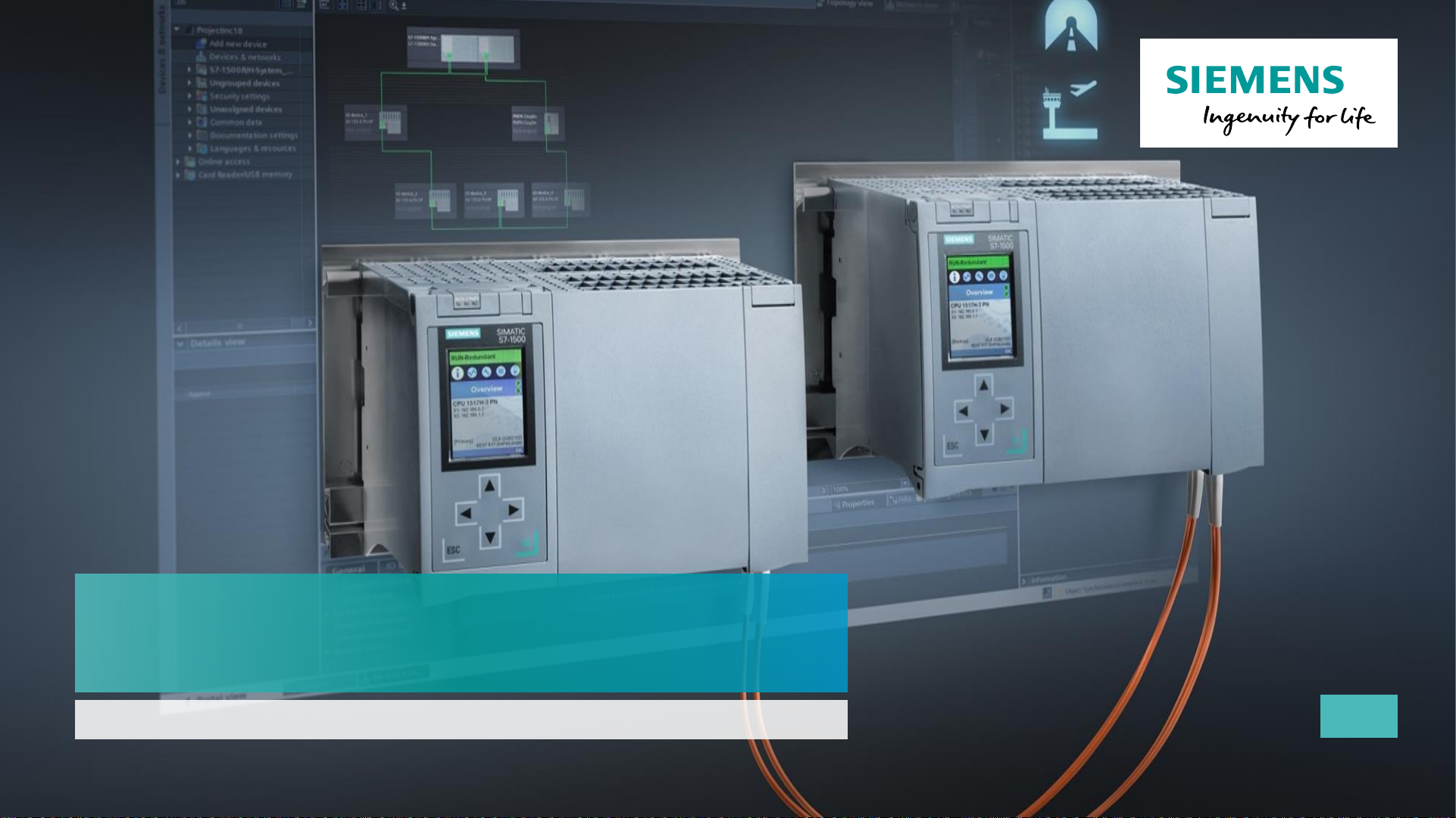
SIMATIC S7-1500R/H
V16
Page 2

Unrestricted © Siemens 2020
Version 2020-12-13
▪ Motivation and Product Strategy
▪ System Overview
▪ System Redundancy and Network Configuration
▪ Communication
▪ S7-1500R/H and Safety
▪ HMI Connection
▪ Installation Recommendations
▪ New Features with TIA Portal V16
▪ Remaining Restrictions
▪ Ordering Information
SIMATIC S7-1500 Redundant Systems
New
Page 3
Unrestricted © Siemens 2020
Version 2020-12-13
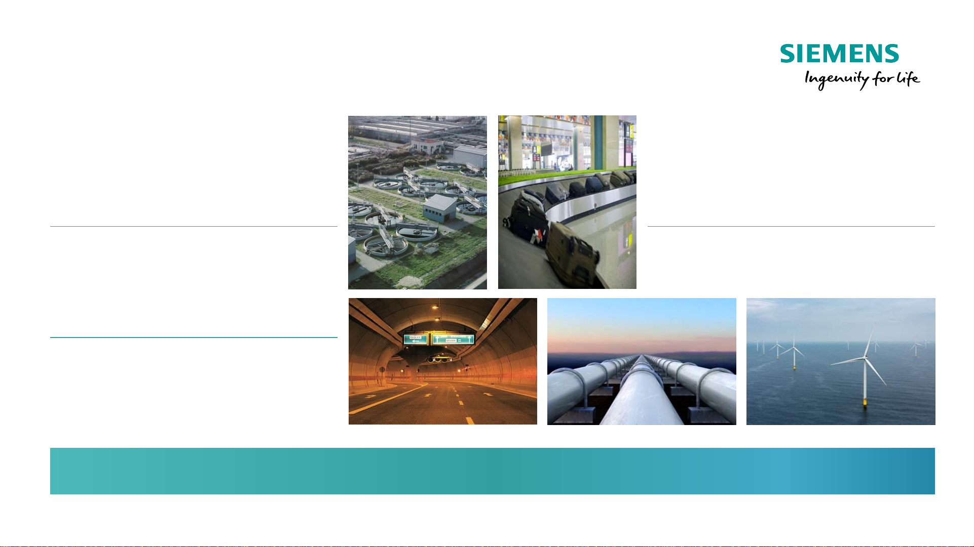
Save on maintenance
Application solutions are mostly
complicated and difficult to maintain
Operation without persons locally
Maintenance trips can be better
planned
Preventing plant downtime
High availability during operation,
Avoidance of loss of production
Redundant systems reduce costs
Prevention of data losses
The data remain intact and long restart
times after a failure are eliminated.
Prevention of damages
Avoidance of unplanned production
stops where the product to be
processed would be permanently
damaged
SIMATIC S7-1500 Redundant Systems
Motivation
Page 4
Unrestricted © Siemens 2020
Version 2020-12-13
SIMATIC S7-1500 Redundant Systems
Product Strategy S7-1500R/H
Based on Standard S7-1500 CPUs and PROFINET
• Basis Hardware Standard-CPUs/Fail-safe CPUs
Transparent Programming
• Standard Engineering Tool TIA Portal
• Redundancy functions fully integrated in TIA Portal
• General handling like standard
• No deep Redundancy Know-How needed
Extensive Scalability
• Scalability of switch-over time
• Scalability of the Redundancy Architecture
• Scalability of the CPU Performance (1513 → 1517)
Step by Step Product Launch Strategy
• First release with basic redundancy functions
• First release will not include all standard and
redundancy functions
• Step by Step increasing of feature set in future versions
Page 5

Unrestricted © Siemens 2020
Version 2020-12-13
SIMATIC S7-1500 Redundant Systems
New
▪ Motivation and Product Strategy
▪ System Overview
▪ System Redundancy and Network Configuration
▪ Failure Scenarios
▪ Communication
▪ S7-1500R/H and Safety
▪ HMI Connection
▪ Installation Recommendations
▪ New Features with TIA Portal V16
▪ Remaining Restrictions
▪ Ordering Information
Page 6
Unrestricted © Siemens 2020
Version 2020-12-13
SIMATIC S7-1500 Redundant Systems
System overview
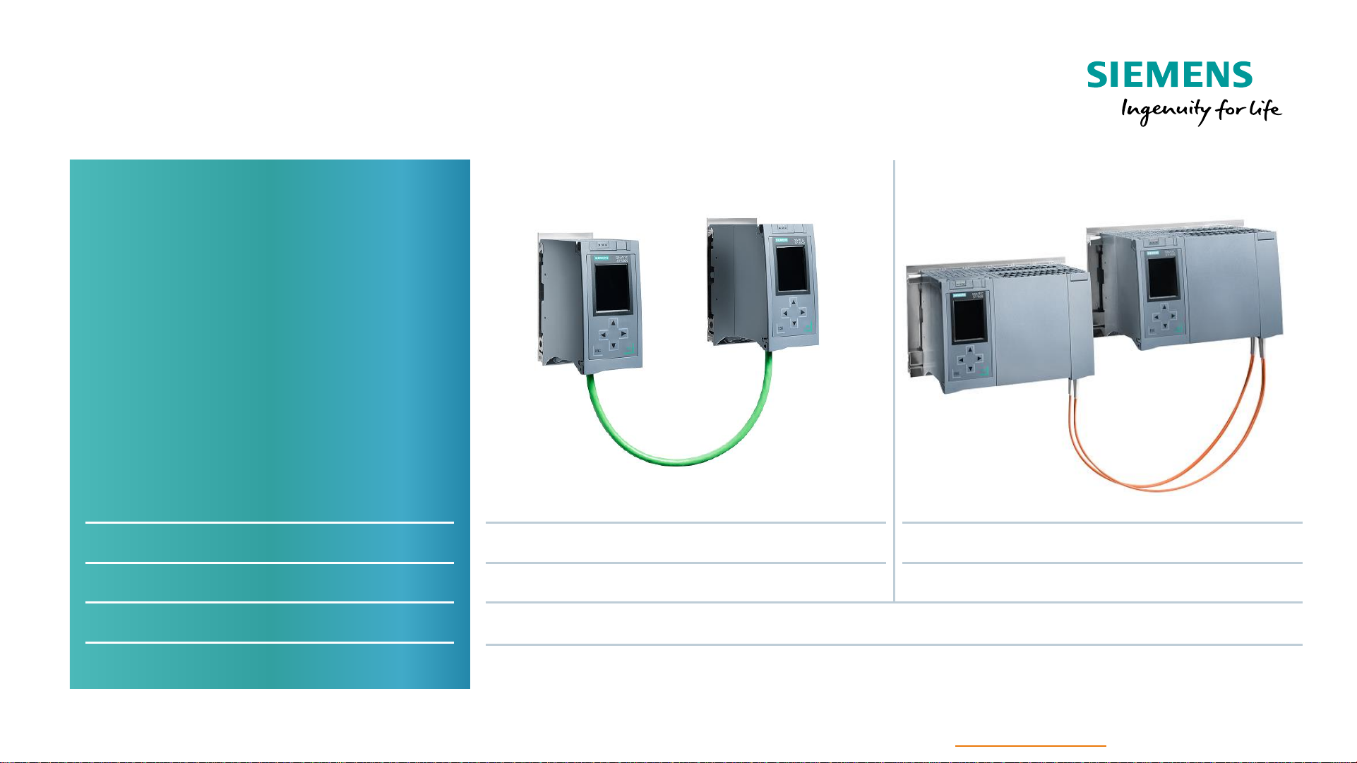
High Available – S7-1500H
CPU 1517H
via Sync-Module
50 ms
Consistent concept –
Identical synchronization
process
Scaling of the switching
performance over the available
bandwidth of the
sync connection
CPU type
Synchronization
Switchover time
I/O systems
Type of connection
Redundant – S7-1500R
CPU 1513R / CPU 1515R
via PROFINET Ring (MRP)
300 ms
ET 200SP and ET 200MP
1)
Single connection (PN redundancy S2) and switched S1
2)
1) ET 200eco PN M12-L in preparation 2) See slide Switched S1 Device
Page 7
Unrestricted © Siemens 2020
Version 2020-12-13
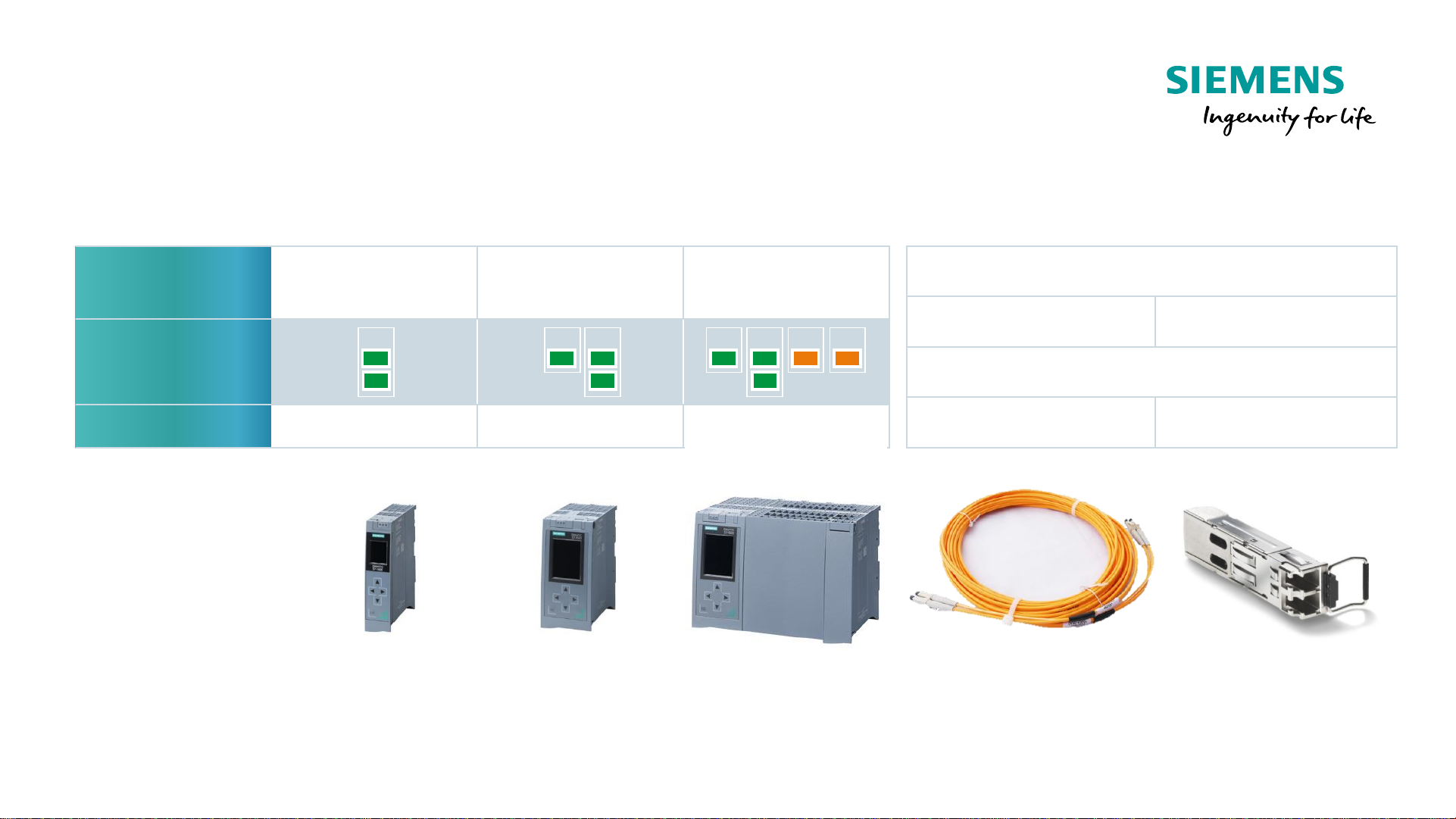
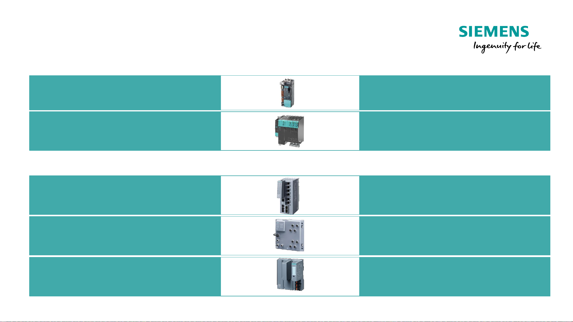
SIMATIC S7-1500 Redundant Systems
PLC Hardware
CPU 1513R
-1 PN
6ES7513-1RL00-0AB0
CPU 1515R
-2 PN
6ES7515-2RM00-0AB0
CPU 1517H
-3 PN
6ES7517-3HP00-0AB0
Program /
memory
350 kB code
1,5 MB data
500 kB code
3 MB data
2 MB code
8 MB data
Interfaces
Firmware
V2.8 V2.8 V2.8
X1 X1 X1X2 X2 X3 X4
Short Distance
<= 10m
Long Distance
<= 10km
Fiber Optic Cable
Plastic Glass fiber
Sync module SFP
6ES7960-1CB00-0AA5 6ES7960-1FB00-0AA5
SFP = Small Form-factor Pluggable
X1: PROFINET IO Controller, Supports RT, MRP, Transport Protocol TCP/IP, Open User Communication
X2: PROFINET Basic Services, Transport Protocol TCP/IP, Open User Communication
Page 8
Unrestricted © Siemens 2020
Version 2020-12-13
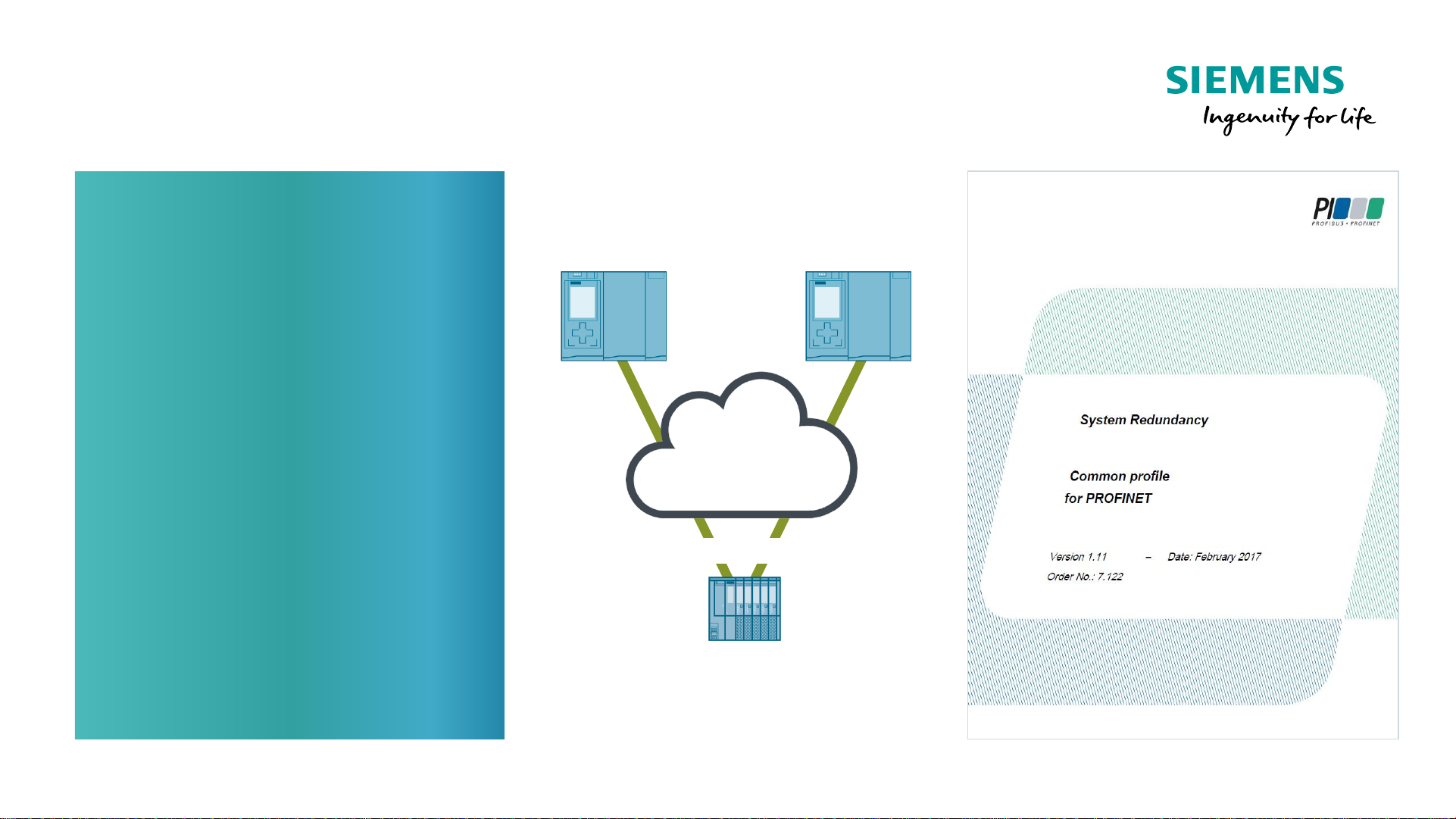
PROFINET System Redundancy
Concept
PROFINET SR
A System with redundant PN
controllers and single or
redundant PN devices.
Three levels:
1. PN Controller
2. PROFINET Network
3. PN Device
Redundancy at one level is
independent of redundancy at
each other level.
PN
Controller
PN
Controller
PN Device
PROFINET
Network
2 or 4 connections
Page 9
Unrestricted © Siemens 2020
Version 2020-12-13
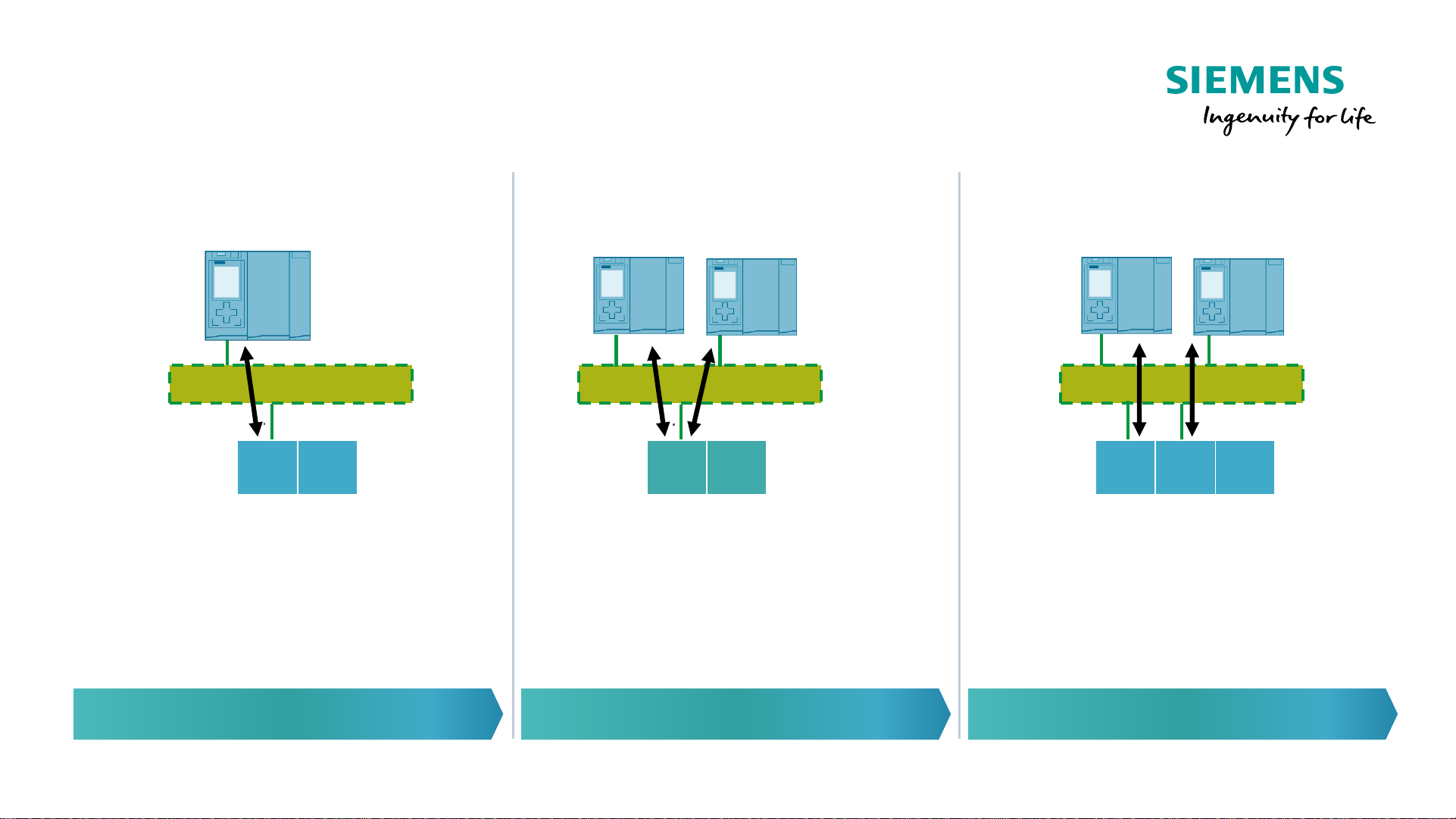
PROFINET System Redundancy
PROFINET IO Network
S1 Device
S → Single interface
1 → one connection to one PLC
IM IO
PROFINET IO Network
IM IO
S2 Device
S → Single interface
2 → can switch between two connections
PROFINET IO Network
IM IOIM
R1 Device
R → Redundant interface
1 → each interface has one connection to
one PLC
Standard PLC + R/H For R/H PLC Future 1500H release
S1 Mode S2 Mode R1 Mode
PLC
Page 10
Unrestricted © Siemens 2020
Version 2020-12-13
PROFINET System Redundancy
Siemens PN IO-Devices with PN S2 Support
ET 200SP - IM155-6PN HF (FW>=4.2)
6ES7155-6AU01-0CN0
6ES7155-6AU30-0CN0
ET 200MP - IM155-5PN HF (FW>=4.2)
now also available with active backplane.
6ES7155-5AA00-0AC0
PN/PN-Coupler 6ES7158-3AD10-0XA0
I/O-Systems
ET 200eco PN M12-L 6ES7 14*-6**00-0BB0
1) In Vorbereitung
New
New
Page 11
Unrestricted © Siemens 2020
Version 2020-12-13
PROFINET System Redundancy
Siemens PN IO-Devices with PN S2 Support
SCALANCE XC-200 Serie 6GK5 2 . . - . . . 00 - 2 . C2
SCALANCE XF204-2BA
6GK5 204-2AA00-2GF2
Switches
SCALANCE XP-200 Serie
6GK5 2 . . - 0 . A00 - . . S6
Drives
S120, CU310-2PN (FW >=5.2)
(with gsdml)
6SL3040-1LA01-0AA0
S120, CU320-2PN (FW>=5.2)
(with gsdml)
6SL3040-1MA01-0AA0
Page 12
Unrestricted © Siemens 2020
Version 2020-12-13
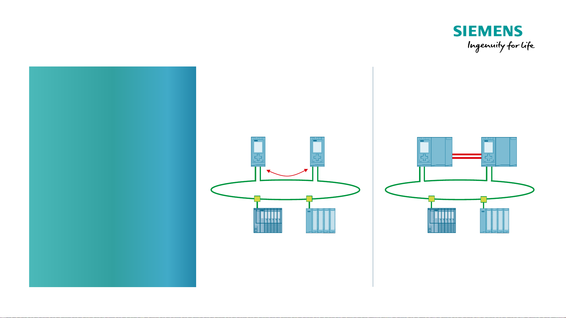
Network Configuration with S7-1500R/H
Requirements
Requirements for the
PROFINET network
configuration
• MRP Ring (default setting in
the configuration)
• PN IO only at X1 interface
• PLC’s need to be part of the
ring
• S7-1500R → no devices in the
connection between the two
PLC‘s
• PN Devices need to support
PN System redundancy
NAP S2 (V1.11)
High Available – S7-1500HRedundant – S7-1500R
Sync
Primary Backup
Single MRP Ring
H-Sync
Primary
Backup
Single MRP Ring
ET 200SP ET 200MP ET 200SP ET 200MP
Max. 16 devices in ring
*)
*) Recommendation
Max. 50 devices in ring
*)
Page 13
Unrestricted © Siemens 2020
Version 2020-12-13
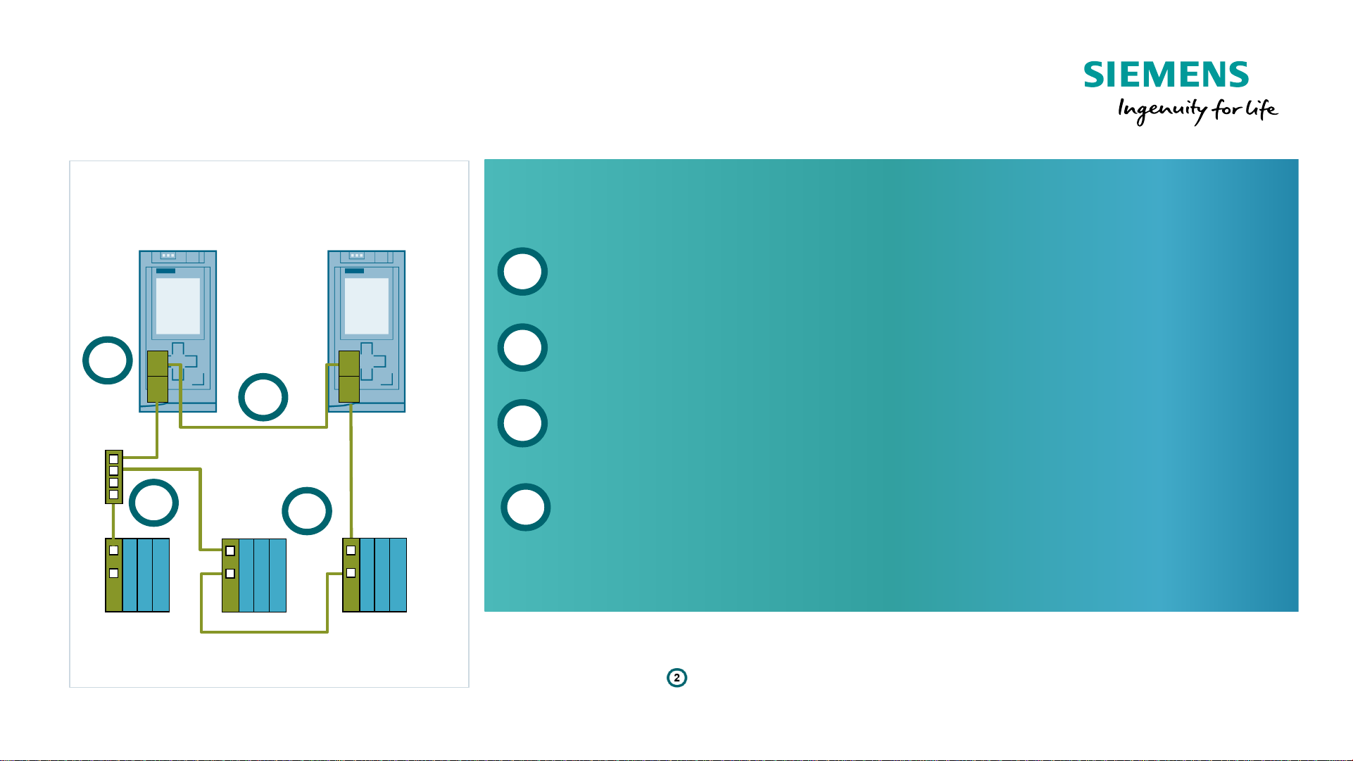
Network Configuration with S7-1500R/H
Basic System Configuration for R-CPU
Structure
MRP-Ring must be connected to the X1 - Port
Synchronization over PN-Ring – no device in this segment
S1 Devices should be connected via a switch to the ring
1)
S2 Devices can be integrated into the ring or also separated
with a switch
1
2
3
PNPN
PN
CPU 151xR
Primary
CPU 151xR
Backup
PN
1
2
3
MRP Ring
4
S1
Switch
S2
S2
4
1) Reason: S1 devices do not forward H-sync telegrams during a MRP reconfiguration phase. This would lead to a high PLC cycle time
in the case that segment is interrupted.
See chapter „H-Sync Forwarding“ in the system manual of S7-1500R/H for details.
Page 14
Unrestricted © Siemens 2020
Version 2020-12-13
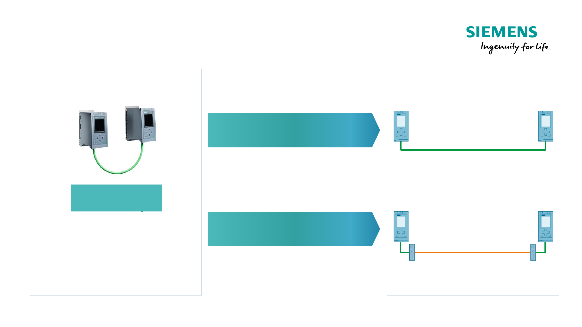
Network Configuration with S7-1500R
Length of the synchronization connection
Direct link up to 100 m
Fiber optic link
(media converter) up to 3 km
≤100 Meter
≤ 3 km
CPU 1513R
CPU 1515R
Page 15
Unrestricted © Siemens 2020
Version 2020-12-13
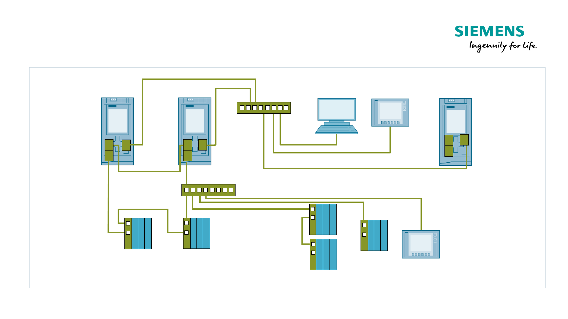
Configuration example
CPU 1515R
Panel
Switch
PNPN
PN
CPU 1515R
Primary
CPU 1515R
Backup
PN
MRP-RING
PN
Switch
PN
PN
PC Standard PLC
Panel
PN
PN
PN
PN
PN
S2S2
S2
S2
S1
Page 16
Unrestricted © Siemens 2020
Version 2020-12-13
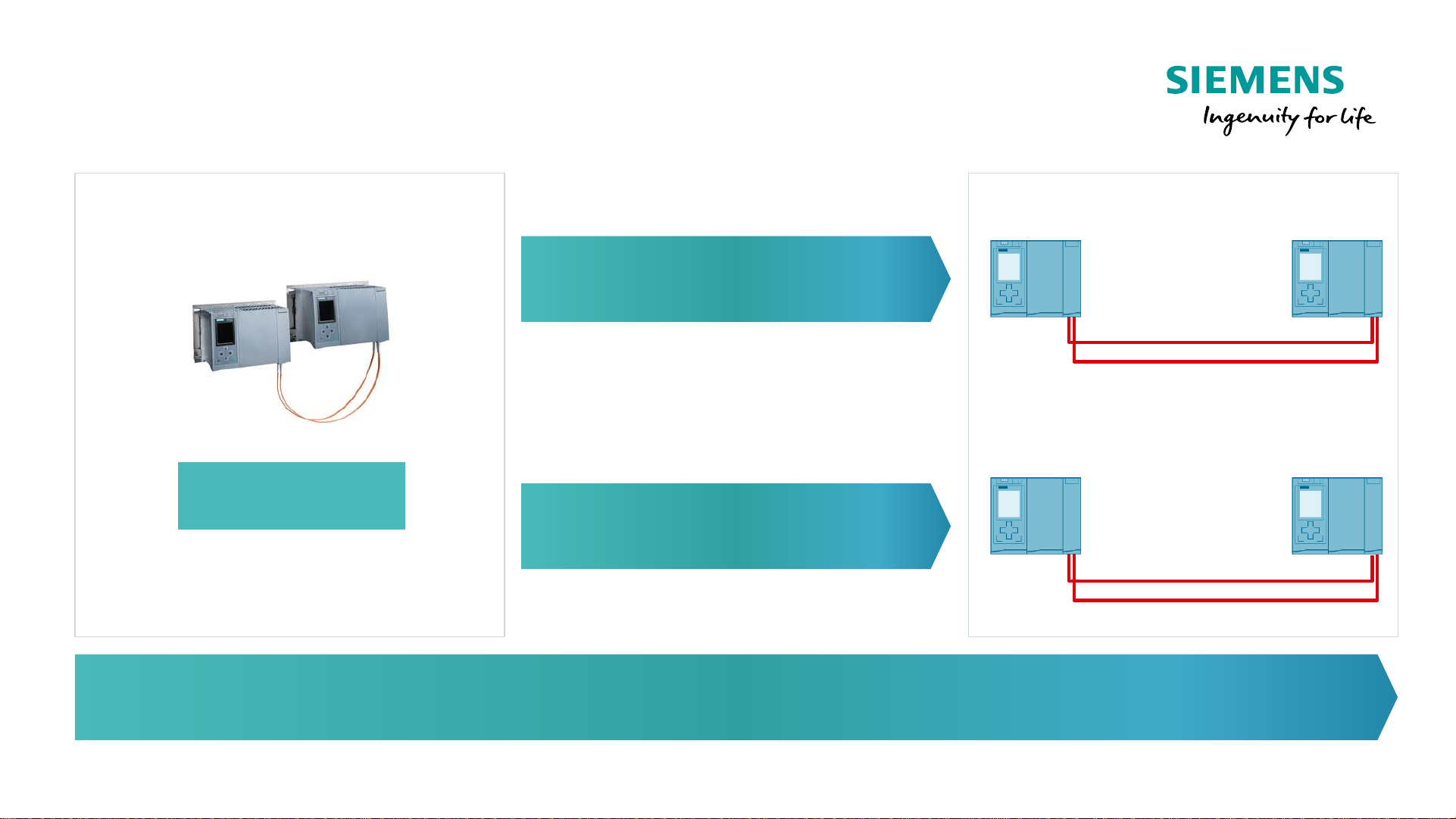
Network Configuration with S7-1500H
Length of the synchronization connection
≤10 Meter
≤10 km
The sync cables are redundant.
The loss of one fiber optic cable has no impact on the runtime behavior.
Short distance Sync modules
up to 10 Meter (LED)
Long distance Sync modules
up to 10 km
CPU 1517H
Page 17
Unrestricted © Siemens 2020
Version 2020-12-13
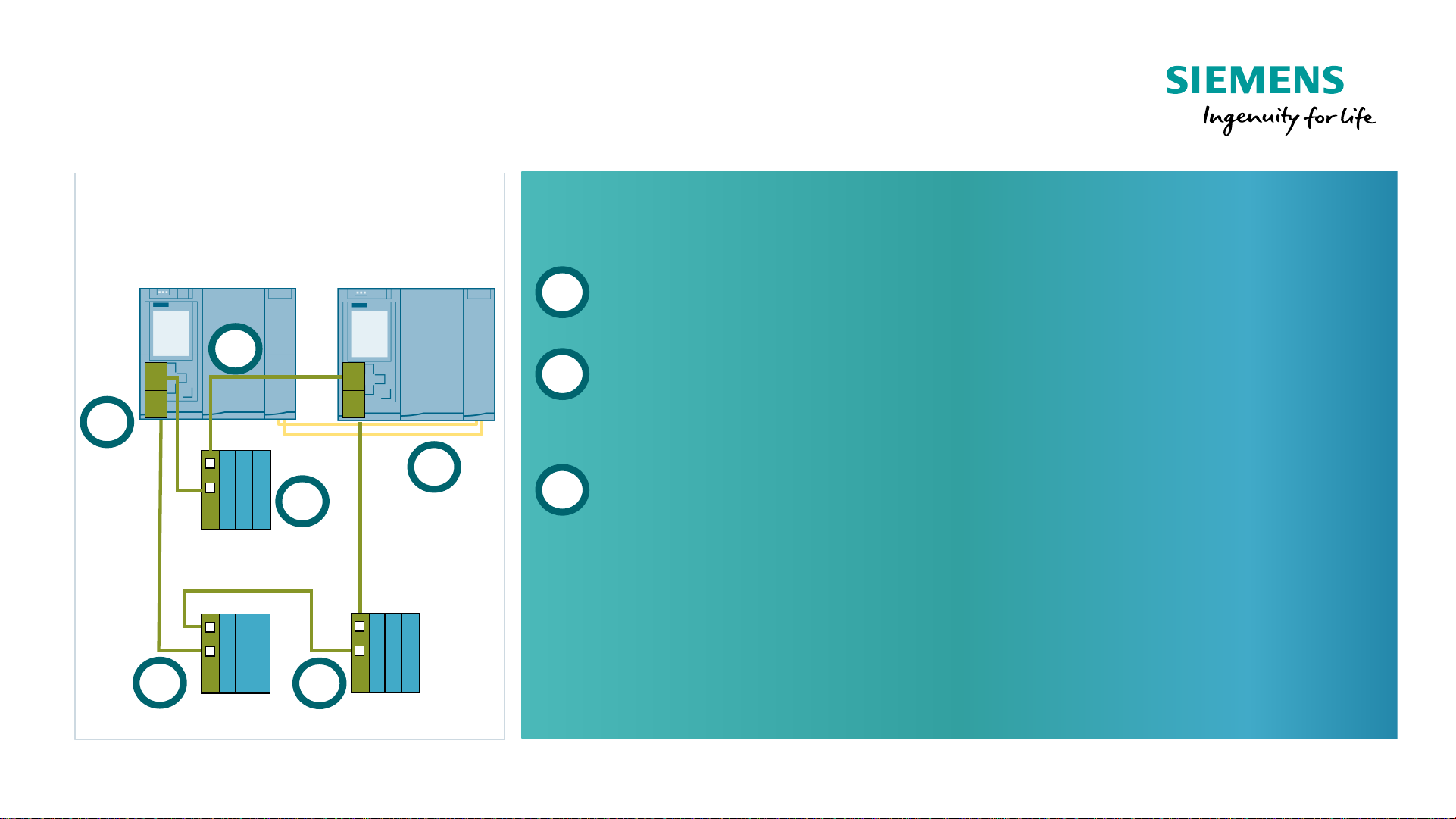
Network Configuration with S7-1500H
Basic System Configuration
CPU 1517H
Primary
CPU 1517H
Backup
1
3
MRP-RING
3
PN
PN
PN
PN
2
2
3
Structure
MRP-Ring must be connected to X1 - Port
Synchronization over Sync-Modules –
Device connection possible
S1 and S2 devices can be integrated into the MRP ring
1
2
3
Page 18

Unrestricted © Siemens 2020
Version 2020-12-13
Configuration example SIMATIC S7-1500H
CPU 1517H
Panel
Switch
PN
PN
CPU 1517H
Primary
CPU 1517H
Backup
PN
MRP-RING
PN
Switch
PN
PN
PC Standard PLC
Panel
PN
PN
PN
PN
PN
PN
FO Sync.
S1S2
S2
S2
S1
S1
Page 19

Unrestricted © Siemens 2020
Version 2020-12-13
SIMATIC S7-1500 Redundant Systems
New
▪ Motivation and Product Strategy
▪ System Overview
▪ Add In and System Redundancy and Network Configuration
▪ Communication
▪ S7-1500R/H and Safety
▪ HMI Connection
▪ Installation Recommendations
▪ New Features with TIA Portal V16
▪ Remaining Restrictions
▪ Ordering Information
Page 20

Unrestricted © Siemens 2020
Version 2020-12-13
Engineering R/H System with TIA Portal Add-in
To connect a PROFINET device to a redundant system S7-1500R/H, it is necessary to set the correct
watchdog time for each device. The S7-1500R/H AddIn, as a context menu function for each PN IO device
connected to an R/H system, calculates the correct factor and updates it in the settings.
Free download: https://support.industry.siemens.com/cs/ww/en/view/109769093
Copy the add in into the folder
.\Program Files\Siemens\Automation\Portal V1x\Add-Ins
Page 21

Unrestricted © Siemens 2020
Version 2020-12-13
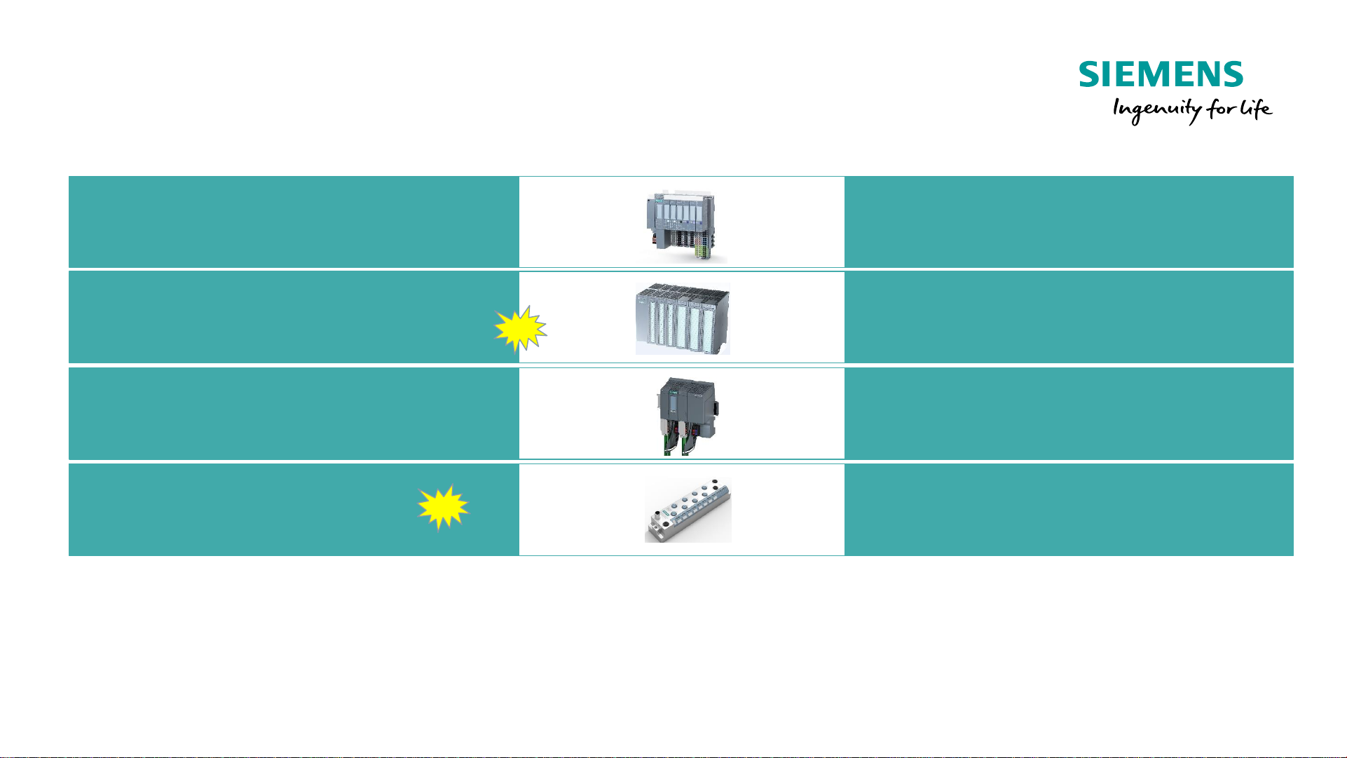
ET 200SP Connectivity
Module
func.
PtP
Connections
Bus
systems
3 Port IM Module
IO
-Link Master
AS
-I Master
Motorstarter
PtP
/ Modbus RTU
•
DALI
•
CAN
•
DMX512
ET200AL System
HART
R/H PROFINET Network configuration –
Connectivity ET200 Stations
H-Sync
Primary Backup
Connectivity ET 200SP
IO
-Link Master
PtP
/ Modbus RTU
Configuration with active backplane possible
64 Channels are now availabel
Connectivity ET 200MP
ET200AL
6ES7 155-6AU30-0CN0
New
Page 22

Unrestricted © Siemens 2020
Version 2020-12-13
SIMATIC S7-1500 / ET 200MP – New products
Summary of 64-channel modules and active backplane bus
Features / functions Benefits
New high-channel ET 200MP modules
64-channel digital modules:
• DI 64x24VDC BA (sinking/sourcing input)
• DQ 64x24VDC/0.3A BA
• DQ 64x24VDC/0.3A SNK BA (sinking output)
• DI 32x24VDC/DQ 32x24VDC/0.3A SNK BA
▪ Optimum price-performance
solution
for price-sensitive applications
▪ Very small footprint due to
greatest possible channel density
▪ Time savings during installation
due to toolless mounting of
shielding and TOP Connect
Active backplane bus / hot swapping
Hot swapping (module replacement during
runtime of the CPU) is possible also with
multiple modules through the use of the
active backplane bus for the ET 200MP. Up
to 12 S7-1500 / ET 200MP modules can be
inserted per station.
Maximum machine/plant
availability because the CPU and
unaffected modules remain in
operation during failure and
replacement of one or more
modules.
High-channel
modules (shifted to 08/2020)
New
New
Active backplane bus
Page 23

Unrestricted © Siemens 2020
Version 2020-12-13
64-channel digital modules
Overview
Type Article number
DI 64x24VDC SNC/SRC BA
6ES7 521
-1BP00-0AA0
DQ 64x24VDC/0.3A BA
6ES7 522
-1BP00-0AA0
DQ 64x24VDC/0.3A SNK BA
6ES7 522
-1BP50-0AA0
DI 32 / DQ 32 x24VDC/0.3A SNK BA
6ES7 523
-1BP50-0AA0
Page 24

Unrestricted © Siemens 2020
Version 2020-12-13
S2 and S1 Devices can be connected
Network Configuration with S7-1500R/H
Connection of PROFINET Devices
H-Sync
Primary
Backup
S2
S2
S1
Switched S1 Mode
1)
(New in V16)
→ Not bump less
Connection of S1 Devices via PN/PN Coupler
with subordinated controller.
→ Bump less Switchover
S2
S1
S1
S1
S2 Mode
→ Bump less Switchover
Subordinated PLC
1) For S7-1500R, S1 devices should be
connected via a switch to the MRP ring
Page 25

Unrestricted © Siemens 2020
Version 2020-12-13
New in V16: Connection without PN/PN coupler is possible
Network Configuration with S7-1500R/H
Connection of Subordinated Controller
H-Sync
Primary
Backup
Option 1:
Integration as iDevice in „Switched S1 Mode“
Currently support only with GSD
→ Communication to RH is temporarily interrupted when a
RH failover occurs.
S2
Option 2:
Via PN/PN Coupler
→ Bump less switchover
S1
1) Not recommended for S7-1500R – see Installation recommendations
Option 3:
Open User Communication between H-
System and subordinated controller
1)
→ Communication to RH is temporarily
interrupted when a RH failover occurs.
Open User Communication
Page 26

Unrestricted © Siemens 2020
Version 2020-12-13
New in V16: Connection without PN/PN coupler is possible
Network Configuration with S7-1500R/H
Connection of PROFIBUS DP Slaves
H-Sync
Primary
Backup
S2
S1
PROFIBUS
PROFIBUS
Please note: IE/PB Link and IE/PB LINK HA are currently not supported
Open User Communication
PROFIBUS
Option 2:
Via PN/PN Coupler
→ Bump less switchover
1) Not recommended for S7-1500R – see Installation recommendations
Option 1:
Integration as iDevice in „Switched S1 Mode“
Currently support only with GSD
→ Communication to RH is temporarily interrupted when a
RH failover occurs.
Option 3:
Open User Communication between H-
System and subordinated controller
1)
→ Communication to RH is temporarily
interrupted when a RH failover occurs.
Page 27

Unrestricted © Siemens 2020
Version 2020-12-13
Network Configuration with S7-1500R/H
Network connections
H-Sync
Primary Backup
As a stitch over a switch
into the ring
As part of the ring
Page 28

Unrestricted © Siemens 2020
Version 2020-12-13
Additional SIMATIC tools –
Overview of existing tools for automation tasks
SINETPLAN
PRONETA
Configuration of the PROFINET devices
• Adjust IP address and device name
• manual / automatic / mass operations
Offline / Online Comparison
• Reference from STEP7 project or PRONETA snapshot
• Incl. check of the ET 200 module configuration
Show details of all modules
▪ Read and compare module configuration
IO test
▪ Automatically logging of IO signal changes
▪ Display device-specific diagnostics
▪ Create and export IO Check protocol
Simulation of the network load depending on topology and network
nodes
▪ Report function with detailed results
▪ Validation of the PROFINET planning guideline
▪ Online scan function
Seemsless integration via API and Standards
▪ Import of the configuration with AutomationML
▪ Import of STEP7 & TIA Portal projects
Port-by-port simulation
Page 29

Unrestricted © Siemens 2020
Version 2020-12-13
SIMATIC S7-1500 Redundant Systems
New
▪ Motivation and Product Strategy
▪ System Overview
▪ Add In and System Redundancy and Network Configuration
▪ Communication
▪ S7-1500R/H and Safety
▪ HMI Connection
▪ Installation Recommendations
▪ New Features with TIA Portal V16
▪ Remaining Restrictions
▪ Ordering Information
Page 30

Unrestricted © Siemens 2020
Version 2020-12-13
SIMATIC S7-1500 Redundant Systems
New
▪ Motivation and Product Strategy
▪ System Overview
▪ Add In and System Redundancy and Network Configuration
▪ Communication
▪ S7-1500R/H and Safety
▪ HMI Connection
▪ Installation Recommendations
▪ New Features with TIA Portal V16
▪ Remaining Restrictions
▪ Ordering Information
Page 31

Unrestricted © Siemens 2020
Version 2020-12-13
Communication
Communication with a
redundant PLC System without
special drivers
H-Sync
X1 X1
X1X1
WinCC / SCADA
Standard Controller
Basic/Comfort Panel
Industrial Ethernet
X2 X2
X2 X2
Third-Party
Page 32

Unrestricted © Siemens 2020
Version 2020-12-13
CPU 1517H SystemCPU 1515R System
Communication
System IP-Address
Accessing the R/H system by
using “System IP-Address”
X1 X1
X1X1
WinCC / SCADA
Standard Controller
Basic/Comfort Panel
Industrial Ethernet
X2 X2
X2 X2
Third-Party
Page 33

Unrestricted © Siemens 2020
Version 2020-12-13
CPU 151xR/H System
Communication
System IP-Address
Standard Controller
Industrial Ethernet
System: IP3
X2: IP1 X2: IP2
Using System IP instead of PLC interface IP
• Transparent communication between standard
PLC and R/H-System
• The standard communication partner is
automatically connected to the primary PLC
Page 34

Unrestricted © Siemens 2020
Version 2020-12-13
CPU 151xR/H System
Communication
System IP-Address
Backup
Standard Controller
Industrial Ethernet
System: IP3
Primary
Connection to IP 3
X2: IP1 X2: IP2
Using System IP instead of PLC interface IP
• Transparent communication between standard
PLC and R/H-System
• The standard communication partner is
automatically connected to the primary PLC
Page 35

Unrestricted © Siemens 2020
Version 2020-12-13
CPU 151xR/H System
Communication
System IP-Address – Switching Primary
Standard Controller
System: IP3
Primary
Industrial Ethernet
Connection to IP 3
X2: IP1 X2: IP2
Using System IP instead of PLC interface IP
• Transparent communication between standard
PLC and R/H-System
• The standard communication partner is
automatically connected to the primary PLC
Page 36

Unrestricted © Siemens 2020
Version 2020-12-13
Network Configuration with S7-1500R/H
Safety Devices
Safety Devices can be integrated via subordinated F-Controller
H-Sync
Primary
Backup
(Non safe) Communication
between RH and F-Controller
via iDevice or Open User
Communication
Safety Applicationis located
in a separated F-Controller
R/H-System (Non Safety) and
connected I/O
Page 37

Unrestricted © Siemens 2020
Version 2020-12-13
Network Configuration with S7-1500R/H
Safety Devices
Safety Devices can be integrated via subordinated F-Controller and PN/PN Coupler
H-Sync
Primary
Backup
MRP Ring
Optional
Usage of a second PN/PN Coupler to
avoid a single point of failure
R/H-System (Non Safety) and
connected I/O
Optional
Media Redundancy (MRP
Ring) increases availability in
case of network breakdown
Safety Applicationis located
in a separated F-Controller
(Non safe) Communication
between RH and F-Controller
via iDevice or Open User
Communication
Page 38

Unrestricted © Siemens 2020
Version 2020-12-13
HMI Connection
via 1 Network (Ring or Line)
X1 X1
Industrial Ethernet
X2 X2
System IP (X2)
Communication between S7-1500R/H and…
Via System-IP
(One HMI-
Connection)
WinCC Comfort V16 (Comfort Panels)
WinCC Advanced V16 (RT Advanced)
OK
WinCC Basic V16 (Basic Panels) OK
WinCC Professional V16 OK
WinCC V7.5 OK
WinCC OA V3.16 OK
Basic/Comfort Panel
WinCC OA
WinCC V7
WinCC V15.1
Page 39

Unrestricted © Siemens 2020
Version 2020-12-13
HMI Connection
via 1 Network (Ring or Line)
X1 X1
Industrial Ethernet
X2 X2
System IP (X2)
WinCC Red.
Communication between S7-1500R/H and…
Via System-IP
(One HMI-
Connection)
WinCC Professional V16 OK
WinCC V7.5 OK
WinCC OA 3.16 OK
WinCC V7.5
WinCC V16
WinCC OA 3.16
WinCC V7.5
WinCC V16
WinCC OA 3.16
Page 40

Unrestricted © Siemens 2020
Version 2020-12-13
SIMATIC S7-1500 Redundant Systems
New
▪ Motivation and Product Strategy
▪ System Overview
▪ Add In and System Redundancy and Network Configuration
▪ Communication
▪ S7-1500R/H and Safety
▪ HMI Connection
▪ Installation Recommendations
▪ New Features with TIA Portal V16
▪ Remaining Restrictions
▪ Ordering Information
Page 41

Unrestricted © Siemens 2020
Version 2020-12-13
Installation Recommendations
for CPU 1513R-1 PN
X1 X1
Basic/Comfort Panel
PN/PN
100MBit/s
OK
Up to14 Devices in
MRP Ring
OK
PN/PN Coupler
Possible, but not recommended
Communication to additional PLC via Open
User Communication via X1
Reason: Generates high load internally and
on Sync-Line1)and increases PLC cycle time
1) Sync-Line runs with 100MBit/s on R-System
Page 42

Unrestricted © Siemens 2020
Version 2020-12-13
Industrial Ethernet
Installation Recommendations
for CPU 1515R-2 PN
X1 X1
X2
Basic/Comfort Panel
WinCC
X2
PN/PN
Standard PLC
100MBit/s
OK
PN/PN Coupler
OK
HMI Connection
via X2
Conditionally recommended
Communication to additional PLC via
Open User Communication via X2
Reason: Generates high load on Sync-
Line1)and increases PLC cycle time
1) Sync-Line runs with 100MBit/s on R-System
OK
Up to14 Devices in
MRP Ring
Possible, but not recommended
Communication to additional PLC via Open
User Communication via X1
Reason: Generates high load internally and
on Sync-Line1)and increases PLC cycle time
Page 43

Unrestricted © Siemens 2020
Version 2020-12-13
Installation Recommendations
for CPU 1517H-3 PN
X1 X1
Industrial Ethernet
X2
Basic/Comfort Panel
WinCC
X2
Subordinated PLCs
PN/PN
1 GBit/s
OK
Up to 48 Devices in
MRP Ring
OK
PN/PN Coupler
OK
Communication to additional
PLC via Open User
Communication via X2
OK
Communication to additional
PLC via Open User
Communication via X1
OK
HMI Connection
via X2
Page 44

Unrestricted © Siemens 2020
Version 2020-12-13
SIMATIC S7-1500 Redundant Systems
New
▪ Motivation and Product Strategy
▪ System Overview
▪ Add In and System Redundancy and Network Configuration
▪ Communication
▪ S7-1500R/H and Safety
▪ HMI Connection
▪ Installation Recommendations
▪ New Features with TIA Portal V16
▪ Remaining Restrictions
▪ Ordering Information
Page 45

Unrestricted © Siemens 2020
Version 2020-12-13
SIMATIC S7-1500 R/H
New Features with V16 and Firmware Version 2.8
Reduction of functional gaps compared with S7
-1500
Support of Alarm SFC’s and Diagnosis SFC‘s
Support of ProDiag und S7-Graph
Support of PNIO SFB’s
Support of Loop Control Blocks (PID)
S7-Routing
New Features and improvements
Connection of standard (non redundant) PN devices: Switched S1
Program Download in Run-Redundant Mode
IP Forwarding
Significantly reduced communication breakdown time during Sync-Up
Page 46

Unrestricted © Siemens 2020
Version 2020-12-13
New in V16: Program Download in RUN-Redundant Mode
The Backup-PLC can remain in RUN redundant during program download
Primary Backup
ET 200SP
ET 200MP
RUN STOP
Primary Backup
ET 200SP
ET 200MP
RUN-Red RUN-Red
V15.1 V16
Benefits:
• No RUN/STOP handling of Backup PLC required
• No SyncUp Phase (with temporary loss of communication)
• User Program is synchronized automatically
Page 47

Unrestricted © Siemens 2020
Version 2020-12-13
New in V16: Mode „Switched S1 Device“
Also devices without System Redundancy Feature (S1) can be connected
Primary Backup
ET 200SP
ET 200MP
ET 200SP
ET 200MP
S2-Devices
e.g. ET 200pro
e.g. G120D
S1-Devices
Primary
Backup
H-Sync
New
System Behavior when
Primary
-Backup switch occurs
S2
-Devices
(with System Redundancy)
S1
-Devices
(without System Redundancy)
Activation time of device
Very short (50ms +) because backup
communication relation is already established
Some seconds (depended on the device
itself) since device is restarted
Behavior of Outputs
Keeps last valid value during failover
If the device supports the function “Hold
last value”
→ no difference to S2
Otherwise: Outputs switches to “0” during
activation time.
Page 48

Unrestricted © Siemens 2020
Version 2020-12-13
New in V16: Mode „Switched S1 Device“
Comparison with System Redundancy S2
Primary Backup
S2
Primary Backup
S1
Initial Situation
Primary AR
Backup AR
Single AR
Failover R/H
RUN Solo
S2
RUN Solo
S1
Backup AR
X
X
Connection established
RUN Solo
S1
X
X
Single AR
Time
Behavior with
System Redundancy S2
Two AR are established
AR = Application Relation
Only 1 AR to primary
PLC established
Backup AR takes over
S2 Device continues communication
AR to primary PLC gets lost
S1 Device without communication
New AR is created by RUN solo PLC to
S1 device
Behavior with
“Switched S1”
Page 49

Unrestricted © Siemens 2020
Version 2020-12-13
New in V16: Mode „Switched S1 Device“
Visualization of redundancy modes in TIA Portal
In the network view S1 and
S2 devices are marked as
„Multi-assigned“
Differences are shown in the column
„Mode“ of the I/O communication table.
Here: ET 200MP is connected as S2
device
Page 50

Unrestricted © Siemens 2020
Version 2020-12-13
SIMATIC S7-1500 R/H
New in V16: Support of STEP 7 Graph
Function
• The graphical engineering language
STEP 7 GRAPH is available for the S7-1500 R/ H
Controller
Benefit of the function
• Graphical programming language for creating of
sequence controls and processes on S7-1500 R/H
CPUs
• Identical behavior regarding used language and
editor for S7-1500 R/H CPUs and „standard“ CPUs
• Depending on the application the user is free to
choose the appropriate programming language
within the engineering of S7-1500 R/H CPUs
Primary
Backup
H-Sync
SCL KOP FUP AWL Graph*
*S7-Graph blocks need because of their functionality an extended processing time within the CPU. This is caused by additional implicit diagnosis, integrated coordination of the program sequence,
the realized operating modes regarding sequence controls
Identical engineering languages for Standard- and S7-1500R/H controllers
Page 51

Unrestricted © Siemens 2020
Version 2020-12-13
New in V16: Support of additional blocks
Advances Instructions
GETIO / GETIO_PART
Read process image
SETIO / SETIO_PART
Transfer process image
GetStationInfo
Read information of an IO device
DeviceStates
Read module state information in an IO system
GEN_DIAG
Generate diagnostics information
Technology
PID_Compact
Universal PID controller with integrated optimization
PID_3Step
PID controller with integrated optimization for valves
PID_Temp
PID controller
for temperature
Program Block
Program_Alarm
Generate program alarm with associated values
Get_AlarmState
Output alarm state
Gen_UsrMsg
Generate user diagnostic messages
Get_Alarm
Read pending alarm
Ack_Alarms
Acknowledge alarms
Page 52

Unrestricted © Siemens 2020
Version 2020-12-13
Restrictions for S7-1500R/H
Restrictions of the configuration for S7
-1500R/H
S7-1500R/H S7-1500 S7-400H
Single PLC projectable
(H/R CPUs as redundant System only)
no N/A yes
Central periphery or central CPs / CMs projectable
no yes yes
Configure System-PS
no yes yes
Only MRP-Ring PN-Networks are supported
(no „open Ring“ like in 400H)
yes no no
Operation as Shared Device or I-Device
no yes no
Page 53

Unrestricted © Siemens 2020
Version 2020-12-13
Restrictions for S7-1500R/H
Functional restrictions for S7
-1500R/H
S7-1500R/H S7-1500 S7-400H
S7-Com, E-Mail, FDL, ISO,
(OUC with dynamic connections is supported)
no
1)
yes yes
OPC UA
no yes no
System-supported H-communication
(but the System IP-Address)
no no yes
Webserver
no yes no
System-supported redundant I/Os
no
2)
no yes
PROFIsafe
no F-CPU yes
Technology Objects
some
3)
yes no
Support for MRPD, clock synchrony and IRT
no yes no
CiR and firmware update in run is supported
no no yes
Direct migration through hardware replacement
(Import of user programs via
Copy/Paste)
no n.a. no
PLCsim and PLCsim advanced are supported
no yes yes
1) S7-Communikation as server is supported
2) Can be realized on application layer: See SIOS article 109767576
3)TO Count, Measuring, PID are supported
Page 54

Unrestricted © Siemens 2020
Version 2020-12-13
CPU S7-1500R
• CPU 1513R-1 PN 6ES7 513-1RL00-0AB0
• CPU 1515R-2 PN 6ES7 515-2RM00-0AB0
CPU S7-1500H
• CPU 1517H-3 PN 6ES7 517-3HP00-0AB0
Distance up to 10m between the S7-1500H PLCs
Use of the Synchronization Modules for
FO cables up to 10 m
• MLFB Module: 6ES7960-1CB00-0AA5
• MLFB LWL-Cable 1m: 6ES7960-1BB00-5AA5
• MLFB LWL-Cable 2m: 6ES7960-1BC00-5AA5
• MLFB LWL-Cable 10m: 6ES7960-1CB00-5AA5
Distance up to 10km between the PLCs
• MLFB Module: 6ES7960-1FB00-0AA5
• Monomode LWL-Cable LC/LC Duplex Crossed 9/125µ
S7-1500H Bundle (Consisting of 2 CPU 1517-3 PN,
4 Sync-Modules 10m and 2 Sync-Cables 1m)
• 6ES7500-0HP00-0AB0
Ordering Information
Page 55

Unrestricted © Siemens 2020
Version 2020-12-13
Thanks for listening
Steve Harris
Applications Engineer Factory Automation
Siemens Australia
DI FA
185 Great Eastern Hwy
Belmont WA 6104
Mobile: +61 427 501 185
steveharris@siemens.com
Restricted © Siemens 2020
 Loading...