

Siemens S7-1500,ET 200pro,ET 200SP Function Manual
___________________
___________________
___________________
___________________
___________________
SIMATIC
S7-1500, ET 200SP, ET 200pro
Structure and Use of the CPU
Memory
Function Manual
10/2018
A5E03461664
-AC
Preface
Documentation guide
1
Memory areas and retentive
memory
2
Memory usage and
application examples
3
SIMATIC memory card
4
Siemens AG
Division Digital Factory
Postfach 48 48
90026 NÜRNBERG
GERMANY
A5E03461664-AC
Ⓟ
09/2018 Subject to change
Copyright © Siemens AG 2013 - 2018.
All rights reserved
Legal information
Warning notice system
This manual contains notices you have to observe in order to ensure your personal safety, as well as to prevent
damage to property. The notices referring to your personal safety are highlighted in the manual by a safety alert
symbol, notices referring only to property damage have no safety alert symbol. These notices shown below are
graded according to the degree of danger.
DANGER
indicates that death or severe personal injury will result if proper precautions are not taken.
WARNING
indicates that death or severe personal injury may result if proper precautions are not taken.
CAUTION
indicates that minor personal injury can result if proper precautions are not taken.
NOTICE
indicates that property damage can result if proper precautions are not taken.
If more than one degree of danger is present, the warning notice representing the highest degree of danger will
be used. A notice warning of injury to persons with a safety alert symbol may also include a warning relating to
property damage.
Qualified Personnel
The product/system described in this documentation may be operated only by
personnel qualified
for the specific
task in accordance with the relevant documentation, in particular its warning notices and safety instructions.
Qualified personnel are those who, based on their training and experience, are capable of identifying risks and
avoiding potential hazards when working with these products/systems.
Proper use of Siemens products
Note the following:
WARNING
Siemens products may only be used for the applications described in the catalog and in the relevant technical
documentation. If products and components from other manufacturers are used, these must be recommended
or approved by Siemens. Proper transport, storage, installation, assembly, commissioning, operation and
maintenance are required to ensure that the products operate safely and without any problems. The permissible
ambient conditions must be complied with. The information in the relevant documentation must be observed.
Trademarks
All names identified by ® are registered trademarks of Siemens AG. The remaining trademarks in this publication
may be trademarks whose use by third parties for their own purposes could violate the rights of the owner.
Disclaimer of Liability
We have reviewed the contents of this publication to ensure consistency with the hardware and software
described. Since variance cannot be precluded entirely, we cannot guarantee full consistency. However, the
information in this publication is reviewed regularly and any necessary corrections are included in subsequent
editions.

Structure and Use of the CPU Memory
Function Manual, 10/2018, A5E03461664-AC
3
Preface
Purpose of the documentation
This documentation describes the various memory areas of the SIMATIC S7-1500
automation system, the SIMATIC S7-1500-based CPU 1516pro-2 and the ET 200SP
distributed I/O system and shows you how to optimally use these memory areas.
In addition, this manual shows you how to reduce work memory utilization by using recipes
and data logs.
Basic knowledge required
The following knowledge is required in order to understand the documentation:
● General knowledge of automation technology
● Knowledge of the SIMATIC industrial automation system
● Knowledge about the use of computers
● Proficiency with STEP 7
Conventions
STEP 7: in this documentation, "STEP 7" is used as a synonym for all versions of the
"STEP 7 (TIA Portal)" configuring and programming software.
Please also observe notes marked as follows:
Note
A note cont
ains important information on the product described in the documentation, on the
handling of the product or on the section of the documentation to which particular attention
should be paid.
Scope of the documentation
This documentation is valid for the central modules of the S7-1500 and ET 200SP systems
and for the ET 200pro CPU 1516pro-2 PN.
The CPUs of the redundant system S7-1500R/H do not support all the memory objects
described in this function manual. The limitations of the redundant S7-1500R/H system are
pointed out where appropriate in the manual. You can find a list of the unsupported functions
in the Redundant System S7-1500R/H
(https://support.industry.siemens.com/cs/ww/en/view/109754833) system manual.
Preface
Structure and Use of the CPU Memory
4 Function Manual, 10/2018, A5E03461664-AC
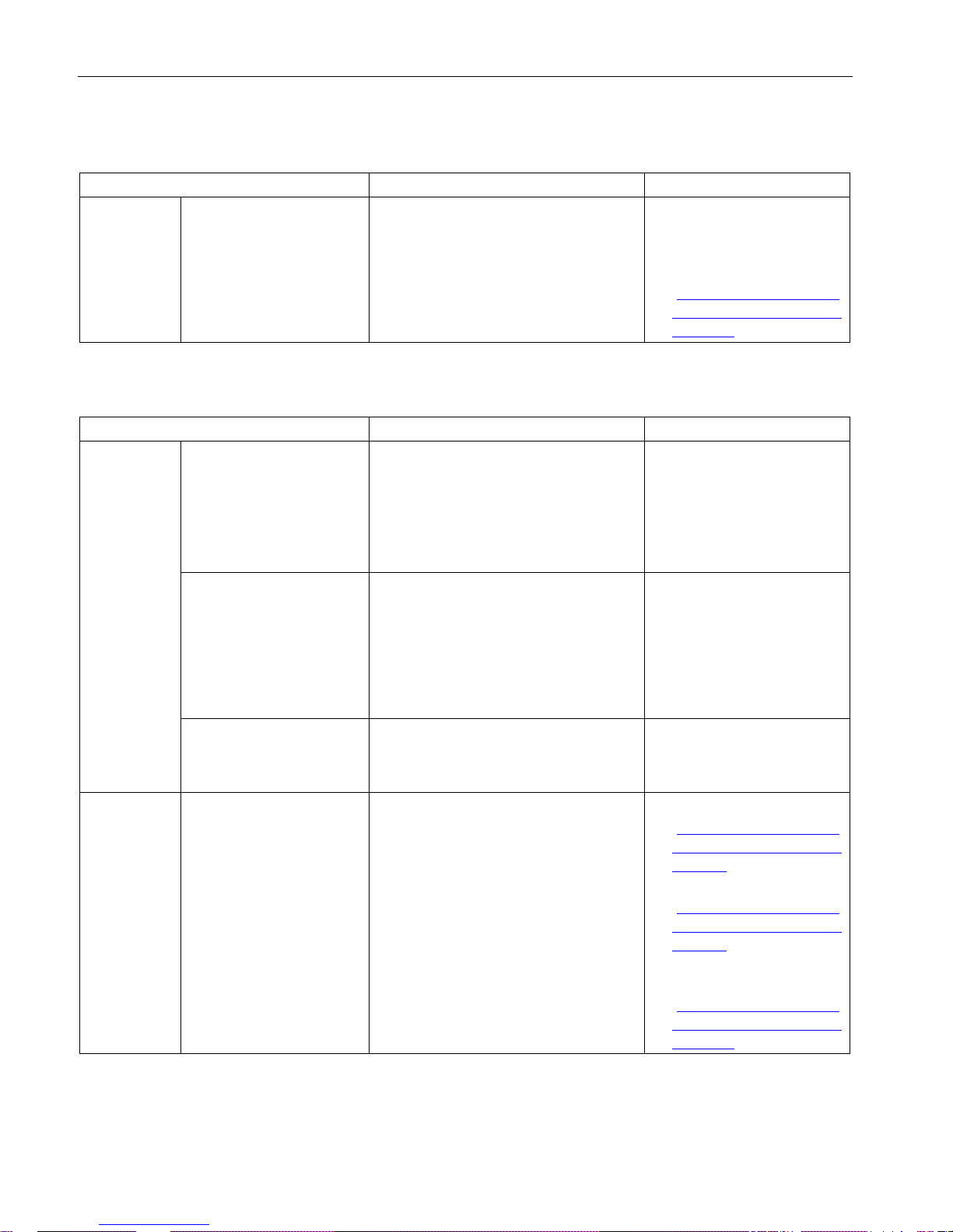
What's new in Edition 10/2018 compared to Edition 09/2016
What's new?
What are the customer benefits?
Where can I find information?
Changed
contents
Scope of the function manual expanded to include the
CPUs of the redundant
system S7-1500R/H.
The CPUs of the redundant system S71500R/H support the memory structure
familiar from the S7-1500 automation
system.
Information on the particularities of the
redundant S7-1500R/H system is provided
where appropriate in the manual.
• In the corresponding sec-
tions of the manual
• System manual Redundant
System S7-1500R/H
(https://support.industry.sie
mens.com/cs/ww/en/view/1
09754833)
What's new in Edition 09/2016 compared to Edition 01/2013
What's new?
What are the customer benefits?
Where can I find information?
New contents Analyzing memory require-
ments and memory usage
You have various options for analyzing the
memory requirements and the memory
usage of the CPU:
• With STEP 7
• With the display of the CPU
• With the web server of the CPU
Section Memory requirements
and memory usage (Page 18)
Memory requirements in
load memory for downloading software changes
When loading software changes to the
SIMATIC memory card, the files in question are only deleted after creation of the
new files. For this reason, the CPU requires adequate free memory space on
the SIMATIC memory card.
You have various options for creating
memory space; these will be explained.
Section Memory requirements
for downloading software
changes (Page 34)
Service life of SIMATIC
memory cards
Using calculation examples of the service
life of a SIMATIC memory card, you can
estimate which SIMATIC memory card is
required for your automation task.
Section Service life of the
SIMATIC memory card
(Page 68)
Changed
contents
Scope of the function manual expanded to include the
CPUs of the ET 200SP
distributed I/O system and
the CPU 1516pro-2 PN
Functions that you will be familiar with
from the SIMATIC S7-1500 CPUs are
implemented in CPUs in other designs
(ET 200SP) and in the CPU 1516pro-2 PN
(degree of protection IP65, IP66 and
IP67).
• Manual CPU 1510SP-1 PN
(https://support.industry.sie
mens.com/cs/ww/en/view/9
0157130)
• Manual CPU 1512SP-1 PN
(https://support.industry.sie
mens.com/cs/ww/en/view/9
0157013)
• Operating instructions CPU
1516pro-2 PN
(https://support.industry.sie
mens.com/cs/ww/en/view/1
09482416)

Preface
Structure and Use of the CPU Memory
Function Manual, 10/2018, A5E03461664-AC
5
Recycling and disposal
For environmentally friendly recycling and disposal of your old equipment, contact a certified
electronic waste disposal company and dispose of the equipment according to the applicable
regulations in your country.
Security information
Siemens provides products and solutions with industrial security functions that support the
secure operation of plants, systems, machines and networks.
In order to protect plants, systems, machines and networks against cyber threats, it is
necessary to implement – and continuously maintain – a holistic, state-of-the-art industrial
security concept. Siemens' products and solutions constitute one element of such a concept.
Customers are responsible for preventing unauthorized access to their plants, systems,
machines and networks. Such systems, machines and components should only be
connected to an enterprise network or the internet if and to the extent such a connection is
necessary and only when appropriate security measures (e.g. firewalls and/or network
segmentation) are in place.
For additional information on industrial security measures that may be implemented, please
visit (https://www.siemens.com/industrialsecurity).
Siemens' products and solutions undergo continuous development to make them more
secure. Siemens strongly recommends that product updates are applied as soon as they are
available and that the latest product versions are used. Use of product versions that are no
longer supported, and failure to apply the latest updates may increase customers' exposure
to cyber threats.
To stay informed about product updates, subscribe to the Siemens Industrial Security RSS
Feed under (https://www.siemens.com/industrialsecurity).

Preface
Structure and Use of the CPU Memory
6 Function Manual, 10/2018, A5E03461664-AC
Siemens Industry Online Support
You can find current information on the following topics quickly and easily here:
●
Product support
All the information and extensive know-how on your product, technical specifications,
FAQs, certificates, downloads, and manuals.
●
Application examples
Tools and examples to solve your automation tasks – as well as function blocks,
performance information and videos.
●
Services
Information about Industry Services, Field Services, Technical Support, spare parts and
training offers.
●
Forums
For answers and solutions concerning automation technology.
●
mySupport
Your personal working area in Industry Online Support for messages, support queries,
and configurable documents.
This information is provided by the Siemens Industry Online Support in the Internet
(https://support.industry.siemens.com).
Industry Mall
The Industry Mall is the catalog and order system of Siemens AG for automation and drive
solutions on the basis of Totally Integrated Automation (TIA) and Totally Integrated Power
(TIP).
You can find catalogs for all automation and drive products on the Internet
(https://mall.industry.siemens.com).

Structure and Use of the CPU Memory
Function Manual, 10/2018, A5E03461664-AC
7
Table of contents
Preface ................................................................................................................................................... 3
1 Documentation guide .............................................................................................................................. 8
2 Memory areas and retentive memory .................................................................................................... 13
2.1 Memory areas ......................................................................................................................... 13
2.1.1 Specifics of the CPUs of the redundant system S7-1500R/H ................................................ 16
2.2 Memory requirements and memory usage ............................................................................. 18
2.3 Retentive memory areas ......................................................................................................... 26
2.4 Summary of retentive behavior ............................................................................................... 30
2.4.1 Retentive behavior of the memory objects ............................................................................. 30
2.5 Memory behavior when loading software changes ................................................................ 32
2.6 Memory requirements for downloading software changes ..................................................... 34
3 Memory usage and application examples .............................................................................................. 38
3.1 Memory usage for recipes ...................................................................................................... 38
3.2 Memory usage for data logging .............................................................................................. 43
3.2.1 Overview of data logging ........................................................................................................ 43
3.2.2 Data structure of the data logs ................................................................................................ 45
3.2.3 Instructions for data logging .................................................................................................... 46
3.2.4 Example program for data logging .......................................................................................... 47
3.2.5 Calculation of the data log size ............................................................................................... 53
4 SIMATIC memory card .......................................................................................................................... 57
4.1 SIMATIC memory card - Overview ......................................................................................... 57
4.2 Setting the card type ............................................................................................................... 64
4.3 Data transfer with SIMATIC memory cards ............................................................................ 65
4.4 Service life of the SIMATIC memory card ............................................................................... 68
4.5 Expanding the load memory of the CPUs of the redundant system S7-1500R/H .................. 73
Glossary ............................................................................................................................................... 74
Index..................................................................................................................................................... 80
Structure and Use of the CPU Memory
8 Function Manual, 10/2018, A5E03461664-AC
1
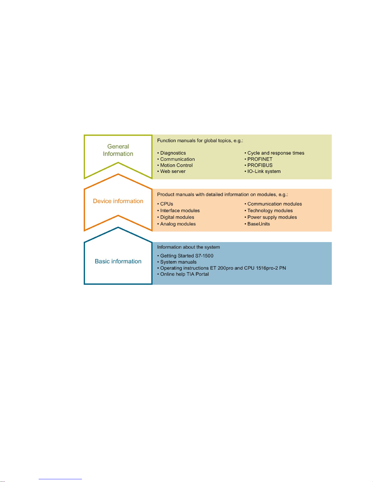
The documentation for the SIMATIC S7-1500 automation system, for CPU 1516pro-2 PN
based on SIMATIC S7-1500, and for the distributed I/O systems SIMATIC ET 200MP,
ET 200SP and ET 200AL is divided into three areas.
This division allows you easier access to the specific information you require.
Basic information
System manuals and Getting Started manuals describe in detail the configuration,
installation, wiring and commissioning of the SIMATIC S7-1500, ET 200MP, ET 200SP and
ET 200AL systems; use the corresponding operating instructions for CPU 1516pro-2 PN.
The STEP 7 online help supports you in configuration and programming.
Device information
Product manuals contain a compact description of the module-specific information, such as
properties, terminal diagrams, characteristics and technical specifications.

Documentation guide
Structure and Use of the CPU Memory
Function Manual, 10/2018, A5E03461664-AC
9
General information
The function manuals contain detailed descriptions on general topics such as diagnostics,
communication, Motion Control, Web server, OPC UA.
You can download the documentation free of charge from the Internet
(https://support.industry.siemens.com/cs/ww/en/view/109742705).
Changes and additions to the manuals are documented in product information sheets.
You will find the product information on the Internet:
● S7-1500/ET 200MP (https://support.industry.siemens.com/cs/us/en/view/68052815)
● ET 200SP (https://support.industry.siemens.com/cs/us/en/view/73021864)
● ET 200AL (https://support.industry.siemens.com/cs/us/en/view/99494757)
Manual Collections
The Manual Collections contain the complete documentation of the systems put together in
one file.
You will find the Manual Collections on the Internet:
● S7-1500/ET 200MP (https://support.industry.siemens.com/cs/ww/en/view/86140384)
● ET 200SP (https://support.industry.siemens.com/cs/ww/en/view/84133942)
● ET 200AL (https://support.industry.siemens.com/cs/ww/en/view/95242965)
"mySupport"
With "mySupport", your personal workspace, you make the best out of your Industry Online
Support.
In "mySupport", you can save filters, favorites and tags, request CAx data and compile your
personal library in the Documentation area. In addition, your data is already filled out in
support requests and you can get an overview of your current requests at any time.
You must register once to use the full functionality of "mySupport".
You can find "mySupport" on the Internet (https://support.industry.siemens.com/My/ww/en).
"mySupport" - Documentation
In the Documentation area in "mySupport" you can combine entire manuals or only parts of
these to your own manual.
You can export the manual as PDF file or in a format that can be edited later.
You can find "mySupport" - Documentation on the Internet
(https://support.industry.siemens.com/My/ww/en/documentation).

Documentation guide
Structure and Use of the CPU Memory
10 Function Manual, 10/2018, A5E03461664-AC
"mySupport" - CAx data
In the CAx data area in "mySupport", you can access the current product data for your CAx
or CAe system.
You configure your own download package with a few clicks.
In doing so you can select:
● Product images, 2D dimension drawings, 3D models, internal circuit diagrams, EPLAN
macro files
● Manuals, characteristics, operating manuals, certificates
● Product master data
You can find "mySupport" - CAx data on the Internet
(https://support.industry.siemens.com/my/ww/en/CAxOnline).
Application examples
The application examples support you with various tools and examples for solving your
automation tasks. Solutions are shown in interplay with multiple components in the system separated from the focus on individual products.
You will find the application examples on the Internet
(https://support.industry.siemens.com/sc/ww/en/sc/2054).
TIA Selection Tool
With the TIA Selection Tool, you can select, configure and order devices for Totally
Integrated Automation (TIA).
This tool is the successor of the SIMATIC Selection Tool and combines the known
configurators for automation technology into one tool.
With the TIA Selection Tool, you can generate a complete order list from your product
selection or product configuration.
You can find the TIA Selection Tool on the Internet
(https://w3.siemens.com/mcms/topics/en/simatic/tia-selection-tool).

Documentation guide
Structure and Use of the CPU Memory
Function Manual, 10/2018, A5E03461664-AC
11
SIMATIC Automation Tool
You can use the SIMATIC Automation Tool to run commissioning and maintenance activities
simultaneously on different SIMATIC S7 stations as a bulk operation, independently of the
TIA Portal.
The SIMATIC automation tool provides a variety of functions:
● Scanning of a PROFINET/Ethernet plant network and identification of all connected CPUs
● Address assignment (IP, subnet, gateway) and station name (PROFINET device) to a
CPU
● Transfer of the date and programming device/PC time converted to UTC time to the
module
● Program download to CPU
● Operating mode switchover RUN/STOP
● CPU localization by means of LED flashing
● Reading out CPU error information
● Reading of CPU diagnostic buffer
● Reset to factory settings
● Updating the firmware of the CPU and connected modules
You can find the SIMATIC Automation Tool on the Internet
(https://support.industry.siemens.com/cs/ww/en/view/98161300).
PRONETA
With SIEMENS PRONETA (PROFINET network analysis), you analyze the plant network
during commissioning. PRONETA features two core functions:
● The topology overview independently scans PROFINET and all connected components.
● The IO check is a fast test of the wiring and the module configuration of a plant.
You can find SIEMENS PRONETA on the Internet
(https://support.industry.siemens.com/cs/ww/en/view/67460624).

Documentation guide
Structure and Use of the CPU Memory
12 Function Manual, 10/2018, A5E03461664-AC
SINETPLAN
SINETPLAN, the Siemens Network Planner, supports you in planning automation systems
and networks based on PROFINET. The tool facilitates professional and predictive
dimensioning of your PROFINET installation as early as in the planning stage. In addition,
SINETPLAN supports you during network optimization and helps you to exploit network
resources optimally and to plan reserves. This helps to prevent problems in commissioning
or failures during productive operation even in advance of a planned operation. This
increases the availability of the production plant and helps improve operational safety.
The advantages at a glance
● Network optimization thanks to port-specific calculation of the network load
● Increased production availability thanks to online scan and verification of existing systems
● Transparency before commissioning through importing and simulation of existing STEP 7
projects
● Efficiency through securing existing investments in the long term and optimal exploitation
of resources
You can find SINETPLAN on the Internet (https://www.siemens.com/sinetplan).
Structure and Use of the CPU Memory
Function Manual, 10/2018, A5E03461664-AC
13
2
2.1
Memory areas
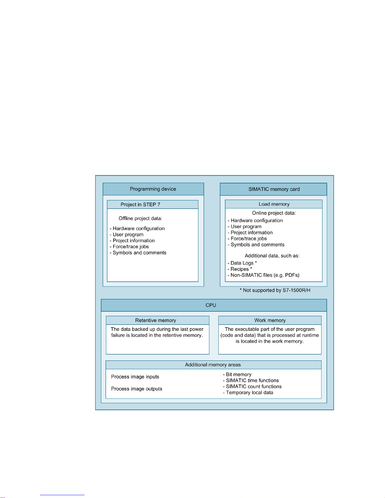
The automation data is located in the automation system in different memory areas.
The offline data of the project created in STEP 7 is located on the hard disk of the
programming device. The online data of the project is located in the load memory on the
SIMATIC memory card. In addition, the work memory, retentive memory and other memory
areas are located on the CPU.
The following figure shows an overview of the memory areas of the CPUs:
Figure 2-1 Memory areas

Memory areas and retentive memory
2.1 Memory areas
Structure and Use of the CPU Memory
14 Function Manual, 10/2018, A5E03461664-AC
Load memory
Load memory is non-volatile memory for code blocks, data blocks, technology objects and
the hardware configuration. This load memory is located on the SIMATIC memory card.
STEP 7 transfers the project data from the programming device to the load memory.
You can copy additional data (e.g. HMI backups and other files) to the SIMATIC memory
card using the web server or Explorer. This data can then be found in the load memory on
the SIMATIC memory card.
Note
An inserted SIMATIC memory card is required to operate the CPU.
Load memory: CPU 1518-4 PN/DP MFP and CPU 1518F-4 PN/DP MFP
On these CPUs additional memory space is used in the load memory by:
● Linux runtime, which runs in parallel with the CPU runtime
● C/C++ runtime applications
● Files that are needed for C/C++ runtime applications
● CPU function libraries
Note
CPU runtime
In the context of the CPU
1518-4 PN/DP MFP and the CPU 1518F-4 PN/DP MFP as well as
the Open Development Kit (ODK), the term "CPU runtime" has the following meaning:
The CPU runtime is the runtime environment in which a CPU runtime application can be
executed. CPU
1518-4 PN/DP MFP and CPU 1518F-4 PN/DP MFP run a Linux runtime in
parallel with the CPU runtime. The Linux runtime is the runtime environment for applications
that are executable in Linux, e.g. C/C++ runtime applications.
For additional information on the CPUs, refer to the CPU
1518-4 PN/DP MFP
(
https://support.industry.siemens.com/cs/ww/en/view/109749061) manual and the
CPU
1518(F)-4 PN/DP MFP
(
https://support.industry.siemens.com/cs/ww/en/view/109756478) product information. You
can find information on creating C/C++ runtime applications in the
SIMATIC
S7-1500 ODK 1500S
(
https://support.industry.siemens.com/cs/ww/en/view/109752683) manual.

Memory areas and retentive memory
2.1 Memory areas
Structure and Use of the CPU Memory
Function Manual, 10/2018, A5E03461664-AC
15
Work memory
The work memory is volatile memory that contains the code and data blocks. The work
memory is integrated into the CPU and cannot be extended. The work memory is only used
in operation of the CPU.
In the CPUs, the work memory is divided into two areas:
● Code work memory: The code work memory contains runtime-relevant parts of the
program code.
● Data work memory: The data work memory contains the runtime-relevant parts of the
data blocks and technology objects.
Tags of global data blocks, instance data blocks and technology objects are initialized
with their start values at the operating states changes below. Retentive tags receive their
actual values saved in the retentive memory.
– POWER ON → STARTUP
– STOP → STARTUP
Work memory of CPU 1518-4 PN/DP MFP and CPU 1518F-4 PN/DP MFP
Additional work memory is needed for use of the CPU function libraries and C/C++ runtime
applications.
Retentive memory
The retentive memory is non-volatile memory for saving a limited amount of data in the event
of power failure.
The following actions delete certain memory objects of the retentive memory:
● Memory reset
● Reset to factory settings
You can find an overview of the retentive behavior of the individual memory objects in
section Retentive behavior of the memory objects (Page 30).
You can find additional information on the memory reset and reset to factory settings
functions in the following manuals:
● System manual S7-1500, ET 200MP Automation System
(http://support.automation.siemens.com/WW/view/en/59191792)
● System manual ET 200SP Distributed I/O System
(http://support.automation.siemens.com/WW/view/en/58649293)
● Operating instructions ET 200pro CPU 1516pro-2 PN
(https://support.industry.siemens.com/cs/ww/en/view/109482416)

Memory areas and retentive memory
2.1 Memory areas
Structure and Use of the CPU Memory
16 Function Manual, 10/2018, A5E03461664-AC
Additional memory areas
Besides the memory areas that have been described for the user program and data, the
CPU has additional memory areas available.
The additional memory areas include the following:
● Process images
● Temporary local data
The CPU-specific sizes can be found in the technical specifications for the respective CPU.
2.1.1
Specifics of the CPUs of the redundant system S7-1500R/H
The redundant system S7-1500R/H consists of two CPUs. A SIMATIC memory card must be
inserted in each of the CPUs. During redundant operation, both CPUs execute the user
program in parallel. In so doing, one CPU takes the role of the leading CPU (Primary CPU)
and one CPU takes the role of the following CPU (Backup CPU). If one CPU fails, the
second CPU maintains control over the process.
Memory areas
The two CPUs of the redundant system S7-1500R/H have the same memory areas as the
CPUs of non-redundant systems.
You create the hardware configuration of the offline project data only once in STEP 7
STEP 7 loads the offline project data into the current primary CPU. The system synchronizes
all data required for redundant operation from the primary CPU to the backup CPU.
Both CPUs receive identical online project data. The online project data contains the
hardware configuration of the H-system.

Memory areas and retentive memory
2.1 Memory areas
Structure and Use of the CPU Memory
Function Manual, 10/2018, A5E03461664-AC
17
Particularities of the retentive memory
Like for non-redundant CPUs, the retentive memory is a non-volatile memory. The retentive
memory saves a limited amount of data in the event of power failure.
Each of the CPUs of the redundant system S7-1500R/H has its own retentive memory. If one
of the CPUs changes to POWER OFF and the second CPU is still in RUN, the retentive data
of the CPU in RUN continues to be updated. If the remaining CPU also goes from RUN to
POWER OFF, the retentive memory of this CPU contains the most up-to-date retentive data.
Note the following for when you switch the CPUs back to RUN afterwards.
Note
Characteristics of retentive data after a STOP or POWER OFF of both CPUs
After a STOP or POWER OFF of both CPUs, switch the CPU with t
he more up-to-date data
to RUN first. The more up
-to-date data is located in the CPU that controlled the process
before STOP or POWER OFF. This procedure gives you certainty that you are using the
most up
-to-date retentive data. The precondition for this is that you did not change any data
using STEP
7 or the HMI while the CPUs were in STOP.
Redundancy ID
Unlike in a non-redundant CPU, an additional memory object is contained in the retentive
memory of the respective redundant CPU. Each CPU saves its respective redundancy ID in
this memory object. The redundancy IDs can assume the values 1 and 2. Different
redundancy IDs are required for redundant operation in order to clearly identify the CPUs
and assign the project data to the respective CPUs. For additional information on
redundancy IDs of the CPUs, refer to the Redundant System S7-1500R/H
(https://support.industry.siemens.com/cs/ww/en/view/109754833) system manual.
You can find an overview of the retentive behavior of the individual memory objects in
section Retentive behavior of the memory objects (Page 30).
Memory areas and retentive memory
2.2 Memory requirements and memory usage
Structure and Use of the CPU Memory
18 Function Manual, 10/2018, A5E03461664-AC
2.2
Memory requirements and memory usage
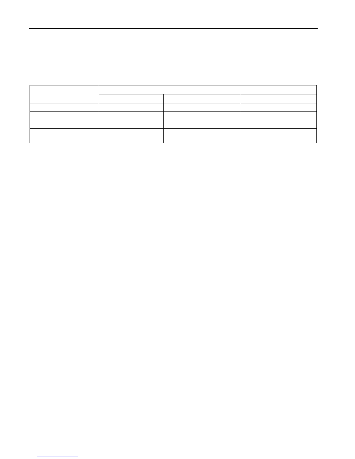
You can access information regarding the memory areas of the CPUs in the following ways
depending on product family used:
Product family
Information regarding the memory areas of the CPU is accessible via:
STEP 7
Web server
Display
S7-1500
✓ ✓ ✓
S7-1500R/H ✓ --
✓
ET 200SP
✓ ✓
--
ET 200pro
CPU 1516pro-2 PN
✓ ✓
--
Memory areas and retentive memory
2.2 Memory requirements and memory usage
Structure and Use of the CPU Memory
Function Manual, 10/2018, A5E03461664-AC
19
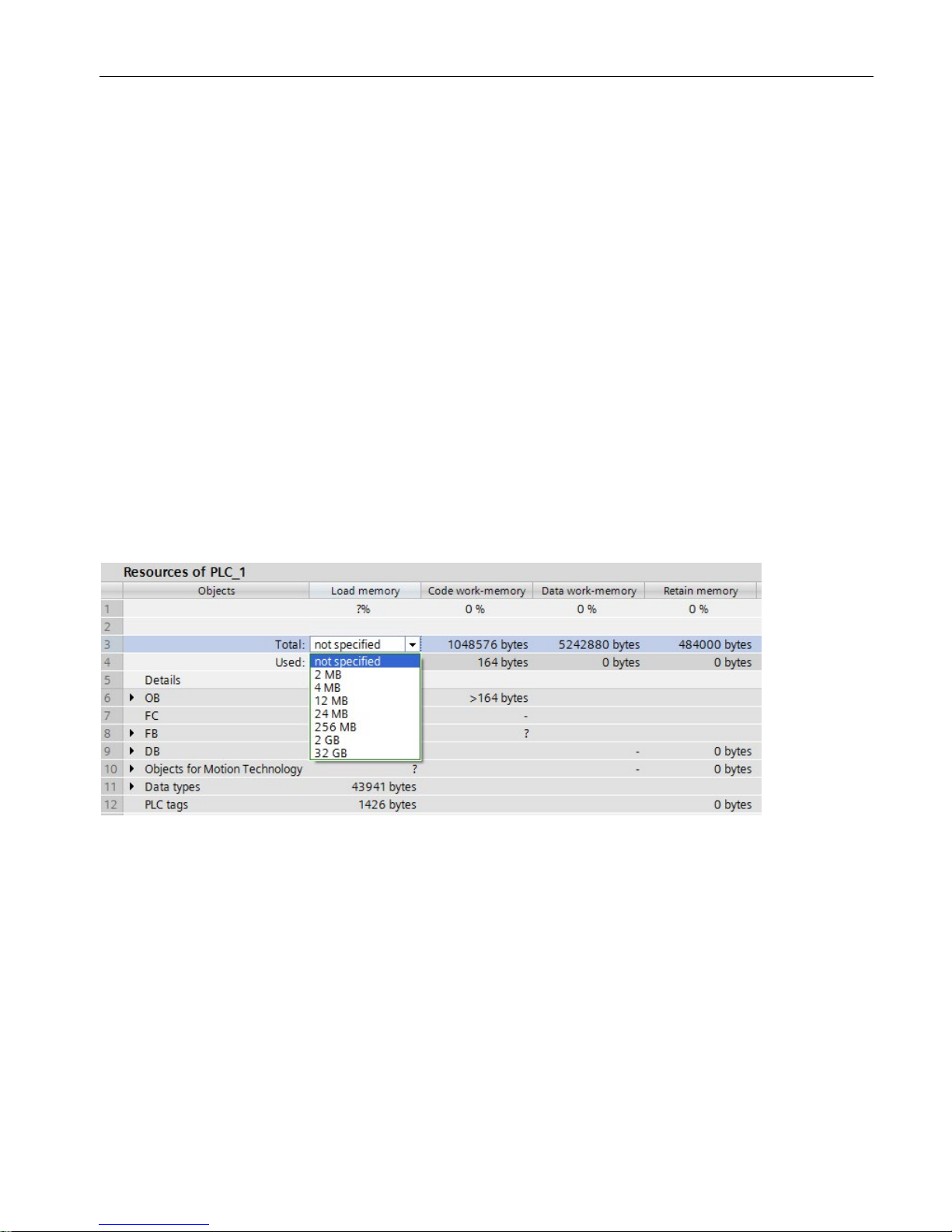
Memory requirements of the program in the offline project
During creation or modification of a project, the display of memory utilization in STEP 7
shows you the size of the project in the following memories:
● Load memory
● Work memory
● Retentive memory
You can find this information for the CPU under "Program info" in the project tree,
"Resources" tab.
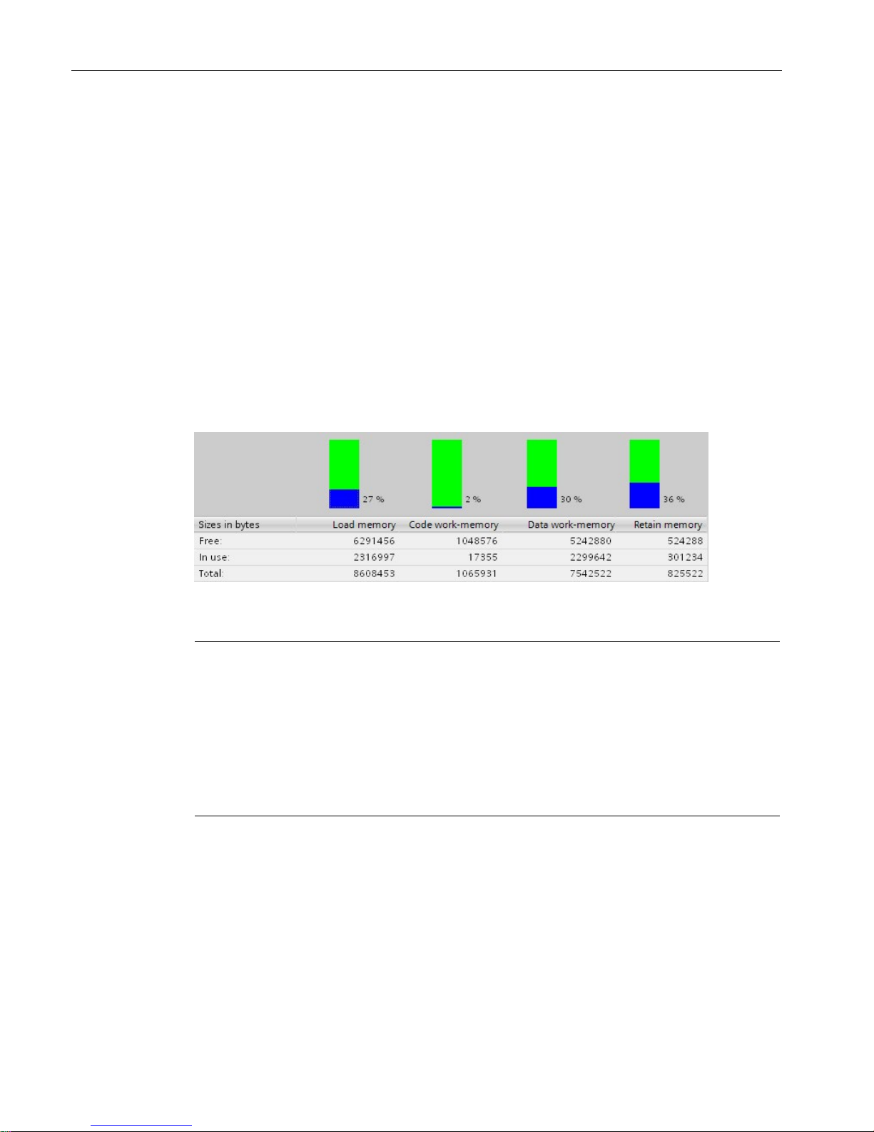
● Total size of the memory areas of the respective CPU project (in the figure below line
"Total:")
● Memory requirements of the program elements (blocks, data types, objects for motion
technology and PLC tags)
● Memory amounts in the respective memory area of the offline project (in figure below, line
"Used:")
● Used inputs and outputs
The following figure shows an overview of the utilization of the various memory areas of the
"Resources" tab:
Figure 2-2 Display of the utilization of the various memory areas

Memory areas and retentive memory
2.2 Memory requirements and memory usage
Structure and Use of the CPU Memory
20 Function Manual, 10/2018, A5E03461664-AC
For a CPU, you can select the total size of the load memory in a drop-down list. Select the
size of the load memory in accordance with the size of the SIMATIC memory card you are
using. The percentage shown in the Load memory column depends on the selected size of
the load memory. As soon as the memory size exceeds the size of the load memory of the
memory card you are using, the sizes indicated turn red.
Note
Determination of the memory utilization
Note that the SIMATIC memory card also contains data other than the user program that you
cannot determine using "Resources". This data includes:
•
Hardware configuration
•
Recipes, data logs and HMI backups (not supported for S7-1500R/H)
•
Non-SIMATIC files, such as PDF, etc.
Therefore, the drop
-down list with the size of your SIMATIC memory card only serves as a
visual orientation aid.
Also refer to the FAQ "How do you estimate the memory requirements of your project in the
load memory of a SIMATIC S7-1500" on the Internet
(https://support.industry.siemens.com/cs/ww/en/view/97553417).
Note
Display of the memory utilization under "Program info"
The display of the memory utilization in the program information is an offline display in
STEP
7 and only shows the memory requirements of the program in the project. The
program on the memory card of the CPU may differ, however, e.g. if the
program:
•
is more up to date
•
contains blocks generated by other projects
•
contains blocks generated on the CPU

Memory areas and retentive memory
2.2 Memory requirements and memory usage
Structure and Use of the CPU Memory
Function Manual, 10/2018, A5E03461664-AC
21
Data on the SIMATIC memory card
In addition to the program and the associated program elements (blocks, data types, objects
for motion control and PLC tags), the following data is also stored on the memory card:
● Hardware configuration
● Project information
● Force jobs
● Trace recordings (not supported for S7-1500R/H)
● Symbols and comments
The following further data may also be found on the memory card:
● Recipes, data logs and HMI backups (not supported for S7-1500R/H)
● Non-SIMATIC files that were copied to the memory card via the web server of the CPU or
offline in Explorer (e.g. PDF files etc.)
Memory areas and retentive memory
2.2 Memory requirements and memory usage
Structure and Use of the CPU Memory
22 Function Manual, 10/2018, A5E03461664-AC
Display of the memory utilization in STEP 7
In online mode, the online function "Memory" provides you with the following up-to-date
memory information:
● Size of the total free and already allocated load memory on the SIMATIC memory card.
● Size of the total free and already allocated work memory, separated by code and data.
● Size of the total free and already allocated retentive memory.
The online function "Memory" can be found in Online & Diagnostics under "Diagnostics >
Memory". You can access the functions under Online & Diagnostics in various ways:
● In the project tree under each configured CPU.
● In the project tree under Online access > Accessible devices, in order to display the
memory utilization of CPUs that were not configured in the project.
● In all views of the device configuration (topology view, network view, device view) by
selecting a CPU with the right mouse button.
Figure 2-3 "Memory" online function
Note
Fill levels of the CPUs of the redundant system S7-1500R/H
The CPUs of the redundant system S7
-1500R/H can have CPU-specific fill levels in non-
redundant operation.
The fill levels of the load memory of the CPUs can differ in redundant operation and non
-
redundant operation (e.g. d
ue to stored PDF files or SIMATIC memory cards of different
sizes).
You can have the memory utilization of both CPU
1 and CPU 2 displayed in STEP 7.
Alternatively to the "Memory" online function, you will also find a display of the current
memory functions on the "Online tools" task card in the "Memory" section.
Memory areas and retentive memory
2.2 Memory requirements and memory usage
Structure and Use of the CPU Memory
Function Manual, 10/2018, A5E03461664-AC
23
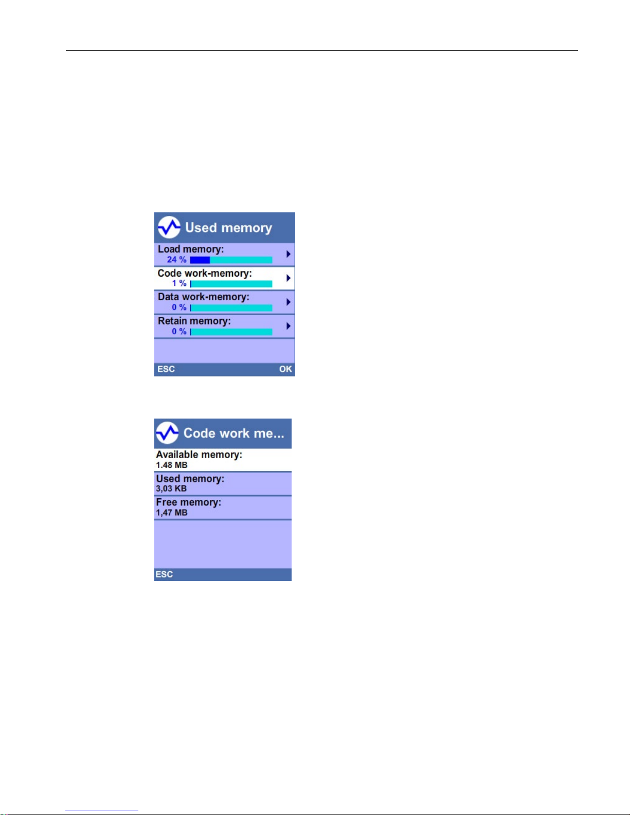
Display of the memory utilization on the display of the CPU
To obtain information about the available memory via the display, proceed as follows:
● Select the "Diagnostics" menu on the display with the help of the arrow keys.
● Select the "Used memory" command from the "Diagnostics" menu.
Under the "Used memory" menu item, you can find information about the utilization of the
various memory areas (see following figure). Note that the memory usage is a snapshot of
the memory used at the time of the request and is not continuously updated.
To find out details about the respective memory areas (e.g. code work memory), select the
required memory area with the help of the arrow keys (see following figure).
In the detail view, e.g. of the code work memory, the display provides you with the following
information:
● Memory space which is still available in the code work memory.
● Memory space which is already allocated in the code work memory.
● Total available memory space in the code work memory.

Memory areas and retentive memory
2.2 Memory requirements and memory usage
Structure and Use of the CPU Memory
24 Function Manual, 10/2018, A5E03461664-AC
Note
Display of the memory utilization of redundant system S7-1500R/H in non-redundant
operation
The CPU displays indicate the local memory utilization of the respective CPU.
Display of the memory utilization of redundant system S7-1500R/H in redundant operation
Irrespective of
the sizes of the inserted SIMATIC memory cards, both CPU displays indicate
the same (synchronized) fill level.
 Loading...