

Siemens S7-1200 TELECONTROL, CP 1242-7 GPRS V2 Operating Instructions Manual

___________________
___________________
___________________
___________________
___________________
___________________
___________________
___________________
___________________
___________________
___________________
___________________
SIMATIC NET
S7-1200 - TeleControl
CP 1242-7 GPRS V2
Operating Instructions
10/2016
C79000
Preface
Application and functions
1
LEDs and connectors
2
Installation, connecting up,
commissioning
3
Configuration and operation
4
Programming the program
blocks
5
Diagnostics and upkeep
6
Technical specifications
7
Dimension drawings
A
Approvals
B
Accessories
C
References
D
-G8976-C311-02

Siemens AG
Division Process Industries and Drives
Postfach 48 48
90026 NÜRNBERG
GERMANY
C79000-G8976-C311-02
Ⓟ
Copyright © Siemens AG 2015 - 2016.
All rights reserved
Legal information
Warning notice system
DANGER
indicates that death or severe personal injury will result if proper precautions are not taken.
WARNING
indicates that death or severe personal injury may result if proper precautions are not taken.
CAUTION
indicates that minor personal injury can result if proper precautions are not taken.
NOTICE
indicates that property damage can result if proper precautions are not taken.
Qualified Personnel
personnel qualified
Proper use of Siemens products
WARNING
Siemens products may only be used for the applications described in the catalog and in the relevant technical
maintenance are required to ensure that the products operate safely and without any problems. The permissible
ambient conditions must be complied with. The information in the relevant documentation must be observed.
Trademarks
Disclaimer of Liability
This manual contains notices you have to observe in order to ensure your personal safety, as well as to prevent
damage to property. The notices referring to your personal safety are highlighted in the manual by a safety alert
symbol, notices referring only to property damage have no safety alert symbol. These notices shown below are
graded according to the degree of danger.
If more than one degree of danger is present, the warning notice representing the highest degree of danger will
be used. A notice warning of injury to persons with a safety alert symbol may also include a warning relating to
property damage.
The product/system described in this documentation may be operated only by
task in accordance with the relevant documentation, in particular its warning notices and safety instructions.
Qualified personnel are those who, based on their training and experience, are capable of identifying risks and
avoiding potential hazards when working with these products/systems.
Note the following:
documentation. If products and components from other manufacturers are used, these must be recommended
or approved by Siemens. Proper transport, storage, installation, assembly, commissioning, operation and
All names identified by ® are registered trademarks of Siemens AG. The remaining trademarks in this publication
may be trademarks whose use by third parties for their own purposes could violate the rights of the owner.
We have reviewed the contents of this publication to ensure consistency with the hardware and software
described. Since variance cannot be precluded entirely, we cannot guarantee full consistency. However, the
information in this publication is reviewed regularly and any necessary corrections are included in subsequent
editions.
for the specific
10/2016 Subject to change
Preface
Validity of this manual
This document contains information on the following product:
CP 1242-7 GPRS V2
Article number 6GK7 242-7KX31-0XE0
Hardware product version 1
Firmware version V2.1.77
Communications processor for connection of the SIMATIC S7-1200 via GSM mobile wireless
networks
CP 1242-7 GPRS V2
Operating Instructions, 10/2016, C79000-G8976-C311-02
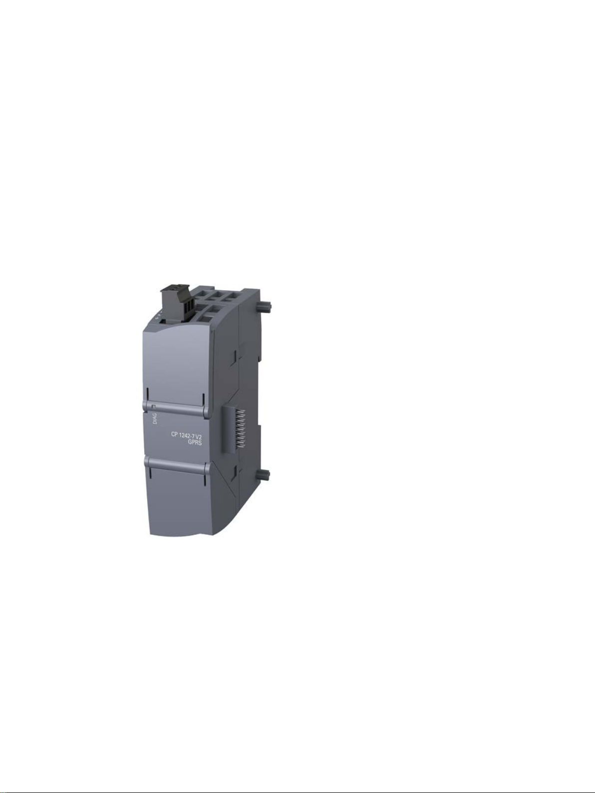
Figure 1 CP 1242-7 GPRS V2
Behind the top hinged cover of the module housing, next to the article number you will see
the hardware product version printed as a placeholder "X" (for example X 2 3 4). In this case,
"X" would be the placeholder for hardware product version 1.
You will find the firmware version of the CP as supplied behind the top hinged cover of the
housing to the left below the LED field.
You will find the IMEI under the lower hinged cover of the housing.
3

Preface
Product names
TCSB
Purpose of the manual
New in this issue
Replaced manual issue
Current manual release on the Internet
Required experience
● CP
In this document, the term "CP" is also used instead of the full product name
"CP 1242-7 GPRS V2".
●
TeleControl Server Basic V3, OPC server for telecontrol communication
This manual describes the properties of this module and supports you when installing and
commissioning the device.
The necessary configuration steps are described in the form of an overview.
You will also find instructions for operation and information about the diagnostics options of
the device.
● New functions in the firmware version named above:
– Changed behavior during time-of-day synchronization, see section Time-of-day
synchronization (Page 46).
– Changed selection of supported data types, see section Datapoint types (Page 67).
– Support of S7 routing
● Editorial revision
Release 01/2015
You will also find the current version of this manual on the Internet pages of Siemens
Industry Online Support:
Link: (https://support.industry.siemens.com/cs/ww/en/ps/15921/man)
To install, commission and operate the CP, you require experience in the following areas:
● Automation engineering
● Setting up the SIMATIC S7-1200
● SIMATIC STEP 7 Basic / Professional
● Data transfer via mobile wireless networks and Internet
CP 1242-7 GPRS V2
4 Operating Instructions, 10/2016, C79000-G8976-C311-02

Preface
Sources of information and other documentation
License conditions
Note
Open source software
The product contains open source software. Read the license conditions for open source
software carefully before using the product.
Firmware
Security information
You will find an overview of further reading and references in the Appendix of this manual.
You will find license conditions in the following document on the supplied data medium:
● OSS_CP124x7_86.pdf
The firmware is signed and encrypted. This ensures that only firmware created by Siemens
can be downloaded to the device.
Siemens provides products and solutions with industrial security functions that support the
secure operation of plants, systems, machines and networks.
In order to protect plants, systems, machines and networks against cyber threats, it is
necessary to implement – and continuously maintain – a holistic, state-of-the-art industrial
security concept. Siemens’ products and solutions only form one element of such a concept.
Customer is responsible to prevent unauthorized access to its plants, systems, machines
and networks. Systems, machines and components should only be connected to the
enterprise network or the internet if and to the extent necessary and with appropriate security
measures (e.g. use of firewalls and network segmentation) in place.
Additionally, Siemens’ guidance on appropriate security measures should be taken into
account. For more information about industrial security, please visit
Link: (http://www.siemens.com/industrialsecurity)
Siemens’ products and solutions undergo continuous development to make them more
secure. Siemens strongly recommends to apply product updates as soon as available and to
always use the latest product versions. Use of product versions that are no longer supported,
and failure to apply latest updates may increase customer’s exposure to cyber threats.
To stay informed about product updates, subscribe to the Siemens Industrial Security RSS
Feed under
Link: (http://www.siemens.com/industrialsecurity).
CP 1242-7 GPRS V2
Operating Instructions, 10/2016, C79000-G8976-C311-02
5

Preface
SIMATIC NET glossary
Training, Service & Support
Explanations of many of the specialist terms used in this documentation can be found in the
SIMATIC NET glossary.
You will find the SIMATIC NET glossary on the Internet at the following address:
Link: (https://support.industry.siemens.com/cs/ww/en/view/50305045)
You will find information on Training, Service & Support in the multi--language document
"DC_support_99.pdf" on the data medium supplied with the documentation.
CP 1242-7 GPRS V2
6 Operating Instructions, 10/2016, C79000-G8976-C311-02

Table of contents
Preface ................................................................................................................................................... 3
1 Application and functions ........................................................................................................................ 9
2 LEDs and connectors ............................................................................................................................ 23
3 Installation, connecting up, commissioning ............................................................................................ 29
4 Configuration and operation .................................................................................................................. 37
1.1 Connecting the S7-1200 to a GSM network ............................................................................. 9
1.2 Communications services ....................................................................................................... 10
1.3 Other services and properties ................................................................................................. 11
1.4 Performance data and configuration limits ............................................................................. 13
1.5 Requirements for operation .................................................................................................... 15
1.6 Configuration examples .......................................................................................................... 17
2.1 Opening the housing ............................................................................................................... 23
2.2 LEDs ....................................................................................................................................... 24
2.3 Electrical connections ............................................................................................................. 27
2.3.1 Wireless interface ................................................................................................................... 27
3.1 Important notes on using the device ....................................................................................... 29
3.1.1 Notices on use in hazardous areas ........................................................................................ 29
3.1.2 Notes on use in hazardous areas according to ATEX / IECEx .............................................. 30
3.1.3 Notices regarding use in hazardous areas according to UL HazLoc ..................................... 31
3.2 Installing the CP and commissioning ...................................................................................... 31
4.1 Notes on operation .................................................................................................................. 37
4.2 Security recommendations ..................................................................................................... 37
4.3 Configuration in STEP 7 ......................................................................................................... 40
4.4 Information required for configuration ..................................................................................... 41
4.5 Connection establishment ...................................................................................................... 43
4.6 Acknowledgment ..................................................................................................................... 44
4.7 The wake-up SMS .................................................................................................................. 44
4.8 Time-of-day synchronization ................................................................................................... 46
4.9 STEP 7 configuration .............................................................................................................. 48
4.9.1 Communication types ............................................................................................................. 48
4.9.2 Mobile wireless communications settings ............................................................................... 49
4.9.3 Ethernet interface (X1) ............................................................................................................ 50
4.9.4 Partner stations ....................................................................................................................... 53
4.9.4.1 Partner stations > Telecontrol server ...................................................................................... 53
CP 1242-7 GPRS V2
Operating Instructions, 10/2016, C79000-G8976-C311-02
7

Table of contents
5 Programming the program blocks .......................................................................................................... 93
6 Diagnostics and upkeep ....................................................................................................................... 105
7 Technical specifications ....................................................................................................................... 113
A Dimension drawings ............................................................................................................................. 117
B Approvals ............................................................................................................................................ 119
C Accessories ......................................................................................................................................... 125
D References .......................................................................................................................................... 129
Index ................................................................................................................................................... 131
4.9.4.2 Partner for inter-station communication ................................................................................. 56
4.9.5 Communication with the CPU ................................................................................................ 57
4.9.6 Security .................................................................................................................................. 59
4.9.6.1 E-mail configuration ............................................................................................................... 60
4.9.7 Data points ............................................................................................................................. 61
4.9.7.1 Configuring data points and messages ................................................................................. 61
4.9.7.2 Datapoint types ...................................................................................................................... 67
4.9.7.3 Status IDs of data points ........................................................................................................ 68
4.9.7.4 Data point index ..................................................................................................................... 69
4.9.7.5 Read cycle ............................................................................................................................. 69
4.9.7.6 Process image, type of transmission, event classes, triggers ............................................... 70
4.9.7.7 "Trigger“ tab ........................................................................................................................... 73
4.9.7.8 Threshold value trigger .......................................................................................................... 74
4.9.7.9 Analog value preprocessing ................................................................................................... 76
4.9.7.10 Partner stations ...................................................................................................................... 82
4.9.8 Messages ............................................................................................................................... 83
4.10 Access to the Web server ...................................................................................................... 86
4.11 TeleService ............................................................................................................................ 87
4.11.1 Configuration of the TeleService access ............................................................................... 87
4.11.2 Establishment of a TeleService connection ........................................................................... 89
5.1 Program blocks for OUC ........................................................................................................ 93
5.2 Programming SMS messages via OUC ................................................................................ 95
5.3 TC_CONFIG for changing configuration data of the CP ........................................................ 98
5.4 IF_CONF: SDT for the configuration data of the CP ............................................................ 100
6.1 Diagnostics options .............................................................................................................. 105
6.2 Firmware download .............................................................................................................. 108
6.3 Module replacement ............................................................................................................ 111
7.1 Technical specifications of the CP ....................................................................................... 113
7.2 Pin assignment of the socket for the external power supply ............................................... 115
C.1 Antenna ................................................................................................................................ 125
C.2 TS Gateway ......................................................................................................................... 125
CP 1242-7 GPRS V2
8 Operating Instructions, 10/2016, C79000-G8976-C311-02

1
1.1
Connecting the S7-1200 to a GSM network
IP-based WAN communication via GSM
Note:
The CP is intended for use in industrial environments.
Using the CP, the S7-1200 SIMATIC controller can be connected to GSM networks. The CP
allows the following types of WAN communication:
● Communication from remote stations to the telecontrol server (TCSB) in the master
station (telecontrol communication)
● Inter-station communication
Communication between stations and the master station (telecontrol communication)
● Direct communication
Direct communication between stations (Open User Communication)
The CP supports the following services for communication via the GSM network and the
Internet:
● GPRS (General Packet Radio Service)
The packet-oriented service for data transmission "GPRS" is handled via the GSM
network.
The CP is not suitable for GSM networks in which the code multiplex method "Code
Division Multiple Access" (CDMA) is used.
● SMS (Short Message Service)
The CP can send and receive SMS messages.
● E-mail
The CP can send e-mails via the GSM network and the Internet.
The CP supports the following frequency bands:
● 850 MHz
● 900 MHz
● 1 800 MHz
● 1 900 MHz
You will find the countries in which the CP is approved on the Internet on the pages of
Siemens Industry Online Support.
Link: (www.siemens.com/mobilenetwork-approvals)
On the Internet page, select the "Entry list" tab and the "Certificates" entry type.
CP 1242-7 GPRS V2
Operating Instructions, 10/2016, C79000-G8976-C311-02
9

Application and functions
1.2
Communications services
Telecontrol communication
Direct communication via Open User Communication (OUC)
1.2 Communications services
The CP 1242-7 GPRS V2 is intended for use in an industrial environment. The following
applications are supported by the CP:
The following applications are possible if telecontrol communication is enabled in the
configuration of the CP.
● Communication with a control center
Remote S7-1200 stations communicate via the mobile wireless network and the Internet
with a telecontrol server in the master station. The telecontrol server communicates with a
higher-level control system using the integrated OPC server function.
● Event-driven sending of messages using SMS or e-mail
Via the mobile wireless network, the CP sends SMS messages to mobile phones or emails to PCs with an Internet connection.
Both types of messages are configured in telecontrol communication in STEP 7. The use
of program blocks is not necessary.
For information on the configuration, refer to sections E-mail configuration (Page 60) and
Messages (Page 83).
● Inter-station communication between S7-1200 stations via the telecontrol server
In this application, the CP establishes a connection to the telecontrol server via the
mobile wireless network. The telecontrol server forwards the messages to the destination
station.
For this communications service, the CP and TCSB use their own protocol on OSI layer 7
that among other things supports certain security functions, see section Other services and
properties (Page 11).
The program blocks of Open User Communication provide the CP with the following
communication options:
● Communication between S7-1200 stations via the mobile wireless network
For this, the CP must be assigned a fixed IP address, see section Other services and
properties (Page 11).
● SMS and e-mail messages via the mobile wireless network
– Sending and receiving SMS messages on mobile phones or S7 stations
– Sending e-mails to PCs with an Internet connection
In contrast to the two corresponding services of telecontrol communication (see above),
to transfer SMS messages/e-mails via OUC, program blocks need to be used, see
section Program blocks for OUC (Page 93).
You will find examples of applications in the section Configuration examples (Page 17).
CP 1242-7 GPRS V2
10 Operating Instructions, 10/2016, C79000-G8976-C311-02

Application and functions
S7 communication
TeleService via the mobile wireless network
1.3
Other services and properties
Other services and properties
Data point configuration
IP configuration
1.3 Other services and properties
Reading / writing data from / to a CPU via the mobile wireless network is possible if S7
communication is enabled in the configuration of the CP.
The following instructions are supported:
● PUT / GET
You will find details on the program blocks in the information system of STEP 7
For S7 communication, the CP requires a fixed IP address, see section Other services and
properties (Page 11).
TeleService is possible if the online functions are enabled in the configuration of the CP.
A TeleService connection can be established between an engineering station (PC with
STEP 7) and a remote S7-1200 station via the mobile wireless network and the Internet.
You can use the TeleService connection for the following purposes:
● Downloading project or program data from the STEP 7 project to the station
● Querying diagnostics data on the station
You will find application examples of the structure in the section Configuration examples
(Page 17).
For more detailed information, refer to section Establishment of a TeleService connection
(Page 89).
●
Due to the data point configuration in STEP 7, programming program blocks in order to
transfer the process data is unnecessary. The individual data points are processed oneto-one in the control system.
●
The CP is assigned a dynamic or a fixed IP address by the mobile wireless network
provider:
– Dynamic IP address
When using telecontrol communication, the mobile wireless network provider generally
assigns the CP a dynamic IP address. You set this in STEP 7 in the parameter group
"Ethernet interface > Ethernet addresses".
– Fixed IP address
To use S7 communication or to receive data via Open User Communication, the CPU
must be reachable via a fixed IP address. In this case, enter the fixed IP address
assigned by the mobile wireless network provider in the same parameter group.
CP 1242-7 GPRS V2
Operating Instructions, 10/2016, C79000-G8976-C311-02
11

Application and functions
Time-of-day synchronization
Access to the Web server of the CPU
Data buffering: Storage of event data
Data transfer is on request or triggered
Logging status data and its transfer to the telecontrol server
Analog value processing
Diagnostics SMS message
1.3 Other services and properties
●
– When telecontrol communication is enabled, the CP obtains its local time of day as
UTC time from the partner (TCSB). The time of day can be read from the CPU. The
mechanisms are described in the STEP 7 information system.
For information on the format of the time stamp, refer to the section Datapoint types
(Page 67).
If telecontrol communication is disabled, the time of day can be obtained from an NTP
server.
– If the security functions are enabled, the secure method NTP (secure) can be used.
For more information, refer to the section Time-of-day synchronization (Page 46).
●
With the aid of the Web server of the CPU, you can read out module data from the
station.
●
If a connection fails, the CP can buffer the data of events of different classes and transfer
them bundled to the telecontrol server.
●
The telecontrol communication with TCSB is triggered in two ways:
– After a request by TCSB or an OPC client connected to TCSB
– Triggered by various selectable criteria
●
For example:
– Data volumes transferred
– ID of the wireless cell in the area of the station
– GSM signal strength
– Communication status
etc.
●
Analog values can be preprocessed on the CP according to various methods.
●
At the request of a mobile phone, the CP sends an SMS message with diagnostics data
to this mobile phone.
CP 1242-7 GPRS V2
12 Operating Instructions, 10/2016, C79000-G8976-C311-02

Application and functions
Security functions of the CP
Encrypted telecontrol communication
Configuring authorized phone numbers on the CP
Telecontrol password
STARTTLS / SMTPS
NTP (secure)
HTTPS
Note
Plants with security requirements - recommendation
If you have systems with high security requirements, use the secure protocols NTP
and HTTPS.
1.4
Performance data and configuration limits
Number of simultaneous connections for telecontrol communication
Number of simultaneous TeleService connections
Number of simultaneous connections for S7 communication and Open User Communication
1.4 Performance data and configuration limits
The CP supports the following Security functions:
●
You configure the interval of the key exchange between the CPU and telecontrol server in
STEP 7 in the parameter group "Ethernet interface (X1) > Advanced options > Transfer
settings".
●
To authorize nodes allowed to establish a connection to the CP during telecontrol
communication.
●
To authenticate the CP with the telecontrol server
●
For the secure transfer of e-mails
●
For secure transfer during time-of-day synchronization (with telecontrol communication
disabled)
●
For secure access to the Web server of the CPU
● 1 reserved connection for user data exchange with the telecontrol server
● Max. 1 TeleService connection
(secure)
A maximum total of 22 connection resources for S7 communication and Open User
Communication (OUC)
CP 1242-7 GPRS V2
Operating Instructions, 10/2016, C79000-G8976-C311-02
13

Application and functions
Number of connections to NTP servers
Number of possible partners for inter-station communication
User data
Number of data points for the data point configuration
Frame memory (send buffer)
1.4 Performance data and configuration limits
The maximum number can be divided up as follows:
● S7 connections: Maximum 8
– (PUT/GET)
● OUC connections: Maximum 8
– TCP connections
– ISO-on-TCP connections
– UDP connections
● Additional free resources for S7 or OUC connections: Maximum 6
● Max. 1 connection to an NTP server
● Max. 13 CPs as partners for inter-station communication
Of which:
– Max. 3 sending partners
– Max. 10 receiving partners
● Partners can be S7-1200 CPs with data point configuration and use of the protocol
"TeleControl Basic".
With the connection types listed below, the user data of a frame represent a consistent data
area in terms of the time of transfer.
User data per frame with the various connection types:
● For TCP connections: Max. 8192 bytes
● For ISO-on-TCP connections: Max. 1452 bytes
● For UDP connections: Max. 1472 bytes
With frames of telecontrol communication, the individual values of the data points are time
stamped.
The maximum number of configurable data points is 200.
The CP has a frame memory (send buffer) for data points configured as an event.
CP 1242-7 GPRS V2
14 Operating Instructions, 10/2016, C79000-G8976-C311-02

Application and functions
Messages: E-mail / SMS
1.5
Requirements for operation
Hardware requirements
Configuration software
Program blocks for Open User Communication and S7 communication
1.5 Requirements for operation
The send buffer has a maximum size of 64 000 events divided into equal parts for all
configured communications partners. The size of the frame memory can be set in STEP 7.
See also section Process image, type of transmission, event classes, triggers (Page 70).
Up to 10 messages can be configured in STEP 7 and sent as e-mails or SMS messages.
Maximum number of characters that can be transferred per SMS message: 160 ASCII
characters including any value sent at the same time
Maximum number of characters that can be transferred per e-mail: 256 ASCII characters
including any value sent at the same time
Apart from the CP. the following hardware is required in the S7-1200:
● A CPU with firmware version as of V4.1
To use the full range of functions, a CPU with a firmware version as of V4.2 is required.
● An external antenna for the CP
Use only the antenna from the accessories program for the CP, refer to the appendix
Antenna (Page 125).
● For telecontrol communication, a PC with an Internet connection is required for the
telecontrol server in the master station.
● If you intend to use TeleService via mobile wireless, a TeleService gateway with Internet
access is required for configurations without a telecontrol server. This is a PC on which
the "TS Gateway" software is installed, see appendix TS Gateway (Page 125).
To use the full range of functions the following configuration tool is required to configure the
module:
STEP 7 Basic V14
For Open User Communication and S7 communication, program blocks are required, see
section Communications services (Page 10).
CP 1242-7 GPRS V2
Operating Instructions, 10/2016, C79000-G8976-C311-02
15

Application and functions
Software for telecontrol communication and TeleService
Requirements for using mobile wireless services
1.5 Requirements for operation
The CP is configured in "Telecontrol" mode.
● For the telecontrol communication
The telecontrol server requires the "TCSB" (TeleControl Server V3) software in the
master station.
● For TeleService
For TeleService a switching station is required between the CP and the engineering
station (with STEP 7 in the version specified above).
This is either the telecontrol server or a TeleService gateway:
– When using telecontrol communication, the telecontrol server is the switching station.
– To use TeleService without a telecontrol server, the "TS Gateway" software is required
for the TeleService gateway.
The software and the manual describing it are on the DVD that ships with the CP.
For the documentation of the application, see /4/ (Page 130) or /3/ (Page 130) in the
References.
● Local availability of a mobile wireless network in the range of the station.
● A contract with a suitable mobile wireless network provider
The contract must allow the transfer of data.
IP address:
– For communication with the telecontrol server, a private (fixed) or public (dynamic) IP
address assigned by the mobile wireless network provider can be used.
– For direct communication between S7 stations (S7 communication and Open User
Communication via T blocks) the mobile wireless network provider must assign a fixed
IP address to the CP and forward the frames to the destination nodes.
● The SIM card and PIN belonging to the mobile wireless contract
The SIM card is inserted in the CP.
With mobile wireless contracts in which the network provider does not assign a PIN, no
PIN is necessary for the configuration of the CP.
● Access point (Access Point)
For the transition between the mobile wireless network and Internet you require an
access point. The name of the access point (APN) and the access data are configured for
the CP in STEP 7.
Generally the mobile wireless network providers make an access point available.
Note the information on APNs in the section Security recommendations (Page 37).
CP 1242-7 GPRS V2
16 Operating Instructions, 10/2016, C79000-G8976-C311-02
Application and functions
1.6
Configuration examples
SMS messages and e-mails
SMS
1.6 Configuration examples
Below, you will find configuration examples for stations with a CP 1242-7 GPRS V2.
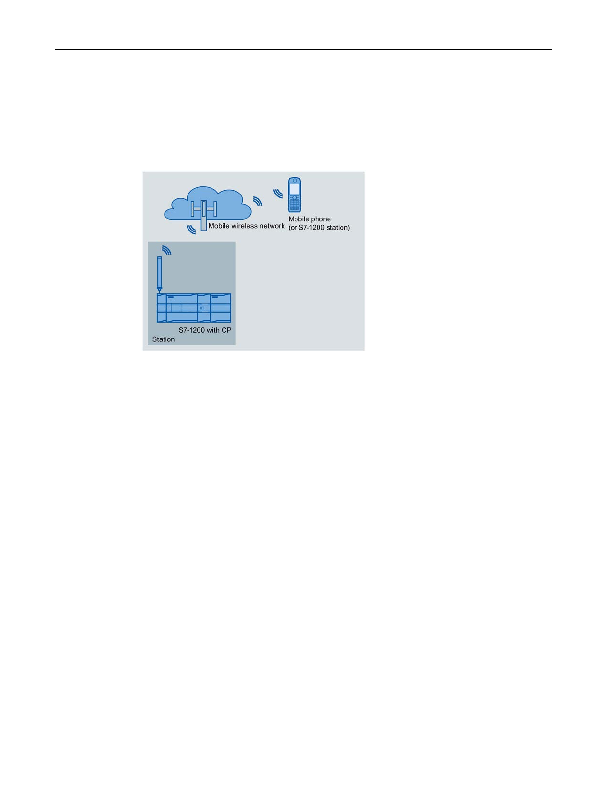
Figure 1-1 Sending messages by SMS from an S7-1200 station
The CP can send SMS messages to a mobile phone or a configured S7-1200 station and
receive from these nodes. The mechanisms for this are as follows:
● SMS messages generated and sent as the result of an event.
For a description of the configuration, refer to the sections Diagnostics and upkeep
(Page 105) and Messages (Page 83).
● SMS messages that are sent or received due to calling the corresponding program blocks
of Open User Communication.
You will find information on the blocks in the section Program blocks for OUC (Page 93),
you will find the description of the programming in the STEP 7 information system.
● Using a mobile phone, a diagnostics SMS can be requested, see section Diagnostics and
upkeep (Page 105).
For all mobile phones that send SMS messages to the CP, the authorize phone number
must be specified in the STEP 7 configuration of the CP (parameter group "Security >
Authorized phone number").
CP 1242-7 GPRS V2
Operating Instructions, 10/2016, C79000-G8976-C311-02
17
Application and functions
E-mails
Telecontrol by a control center
1.6 Configuration examples
The CP can send e-mails to a PC with an Internet connection or a mobile phone. The
mechanisms for this are as follows:
● E-mails generated and sent as the result of an event.
For a description of the configuration, refer to the sections Configuring data points and
messages (Page 61), Messages (Page 83) and E-mail configuration (Page 60).
● E-mails sent as a result of calling the program block TMAIL_C.
You will find information on the blocks in the section Program blocks for OUC (Page 93),
you will find the description of the programming in the STEP 7 information system.
If you want to use the secure transfer of e-mails, the CP must have the current time of day.
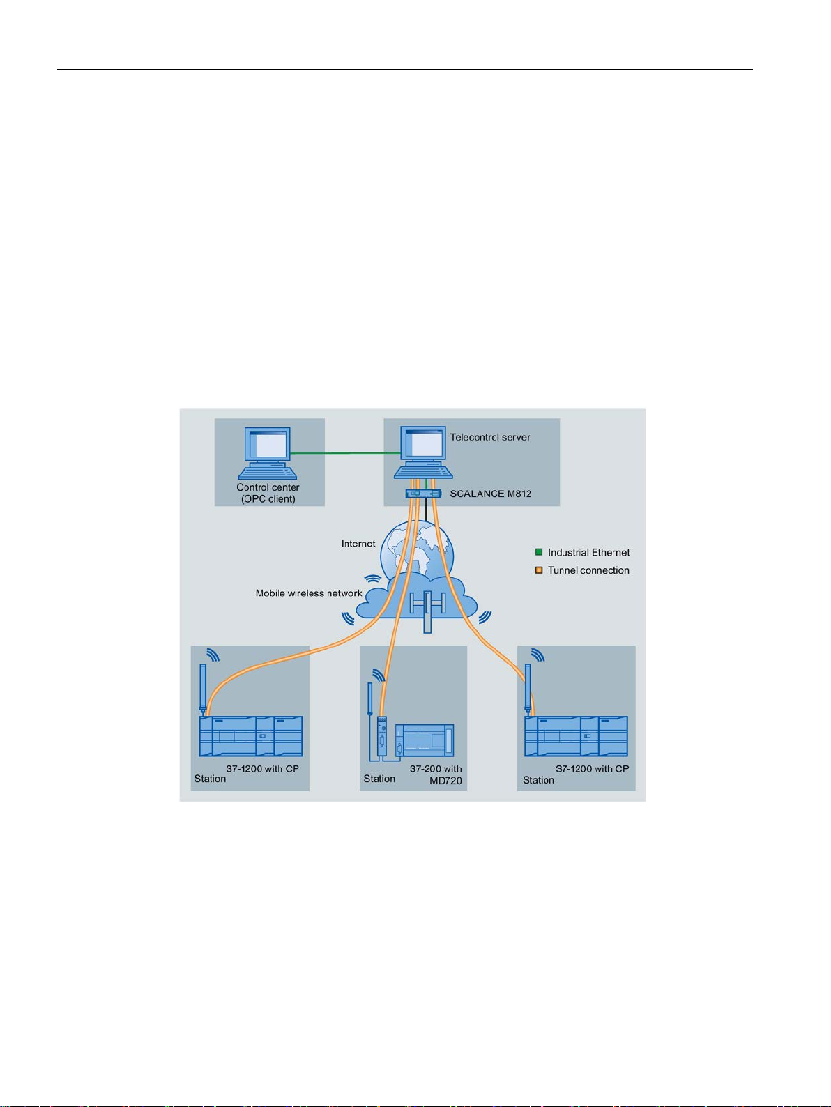
Figure 1-2 Communication between S7-1200 stations and a control center
In the telecontrol applications, the CP communicates with a telecontrol server with an
Internet connection via the mobile wireless network. The "TeleControl Server Basic V3"
(TCSB) application is installed on the telecontrol server in the master station. This results in
the following use cases:
CP 1242-7 GPRS V2
18 Operating Instructions, 10/2016, C79000-G8976-C311-02
Application and functions
Direct communication between stations
TeleService via the mobile wireless network
1.6 Configuration examples
● Communication between a station and a control room with OPC client
The station communicates with the telecontrol server. Using its integrated OPC server,
the telecontrol server exchanges data with the OPC client of the control room.
The OPC client and telecontrol server can be located on a single computer, for example
when TCSB is installed on a control center computer with WinCC.
● Inter-station communication via a control center
Inter-station communication is possible with S7 stations equipped with a suitable
telecontrol CP: CP 1243-1, CP 1242-7 GPRS V2, CP 1243-7 LTE
To allow inter-station communication, the telecontrol server forwards the messages of the
sending station to the receiving station.
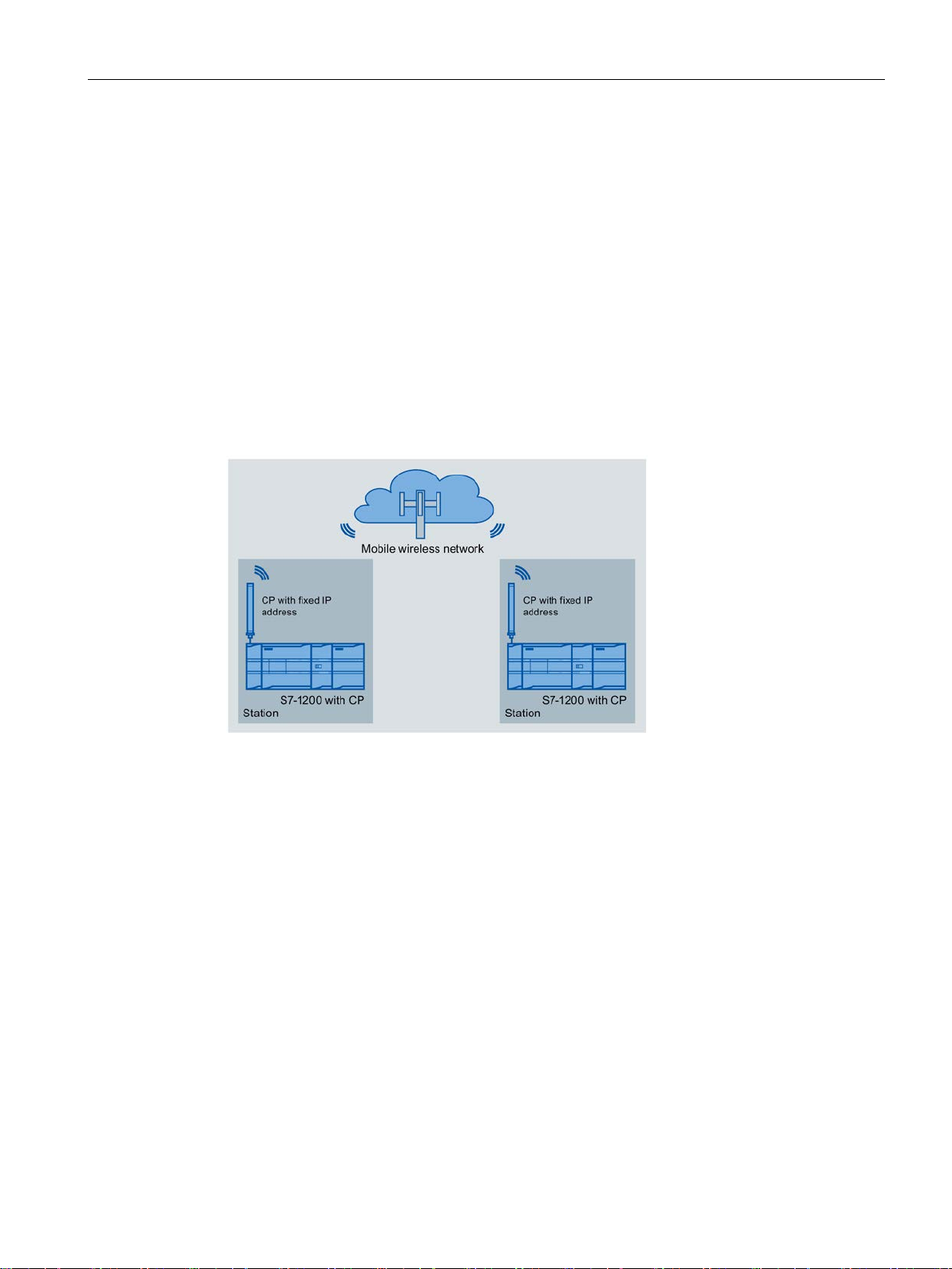
Figure 1-3 Direct communication between two S7-1200 stations
In this configuration, two SIMATIC S7-1200 stations communicate directly with each other
using the CP via the mobile wireless network. Each CP has a fixed IP address. The relevant
service of the network provider must allow this.
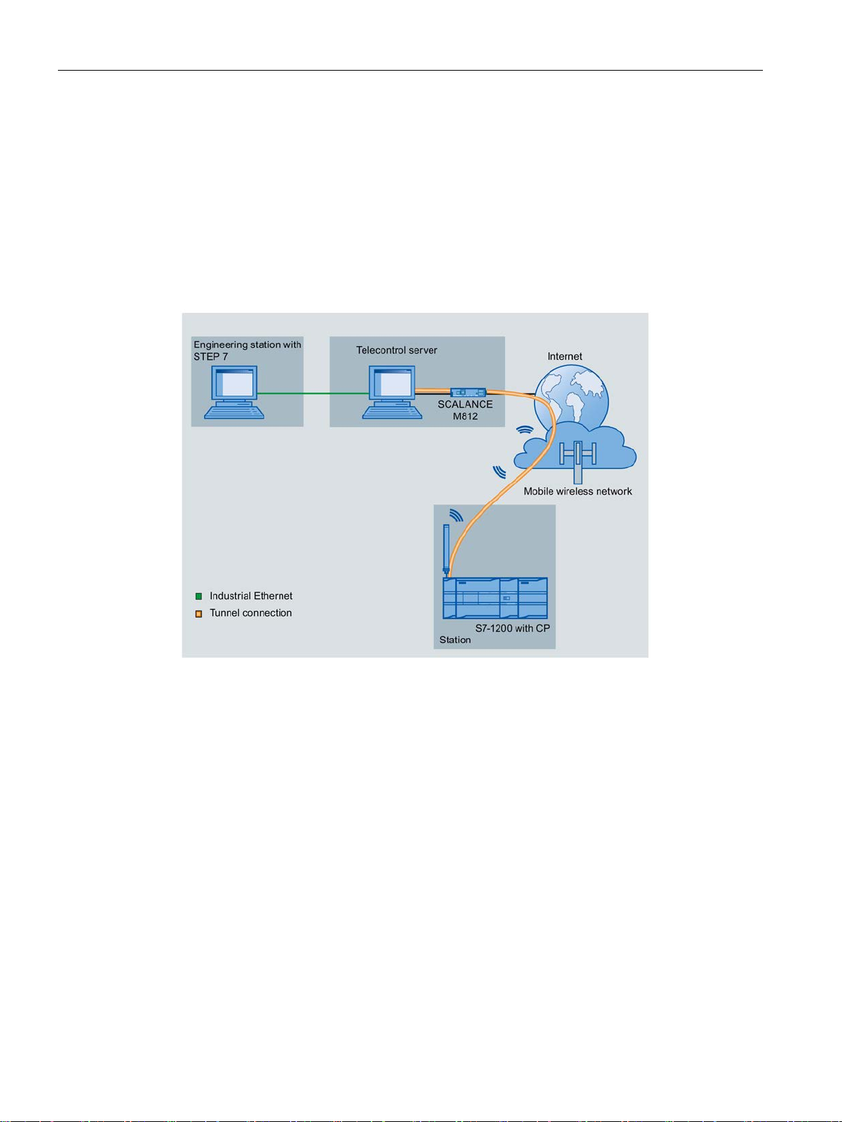
In TeleService via the mobile wireless network, an engineering station on which STEP 7 is
installed communicates via the mobile wireless network and the Internet with the CP in the
S7-1200.
Since the firewall of the network provider is normally closed for connection requests from the
outside, a switching station between the remote station and the engineering station is
required. This switching station can be a telecontrol server or, if there is no telecontrol server
in the configuration, a TeleService gateway.
CP 1242-7 GPRS V2
Operating Instructions, 10/2016, C79000-G8976-C311-02
19
Application and functions
TeleService with telecontrol server
1.6 Configuration examples
The connection runs via the telecontrol server.
● The engineering station and telecontrol server are connected via the Intranet (LAN) or
Internet.
● The telecontrol server and remote station are connected via the Internet and via the
mobile wireless network.
The engineering station and telecontrol server can also be the same computer; in other
words, STEP 7 and TCSB are installed on the same computer.
Figure 1-4 TeleService via the mobile wireless network in a configuration with telecontrol server
CP 1242-7 GPRS V2
20 Operating Instructions, 10/2016, C79000-G8976-C311-02
Application and functions
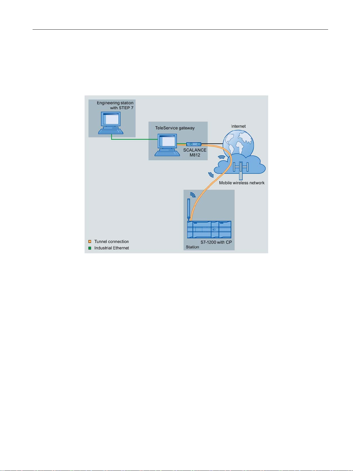
TeleService with TeleService gateway (via LAN)
1.6 Configuration examples
The connection between the engineering station and S7 station is via the TeleService
gateway.
The engineering station is connected to the TeleService gateway via LAN.
Figure 1-5 TeleService via the mobile wireless network with TeleService gateway - connection via
LAN
CP 1242-7 GPRS V2
Operating Instructions, 10/2016, C79000-G8976-C311-02
21
Application and functions
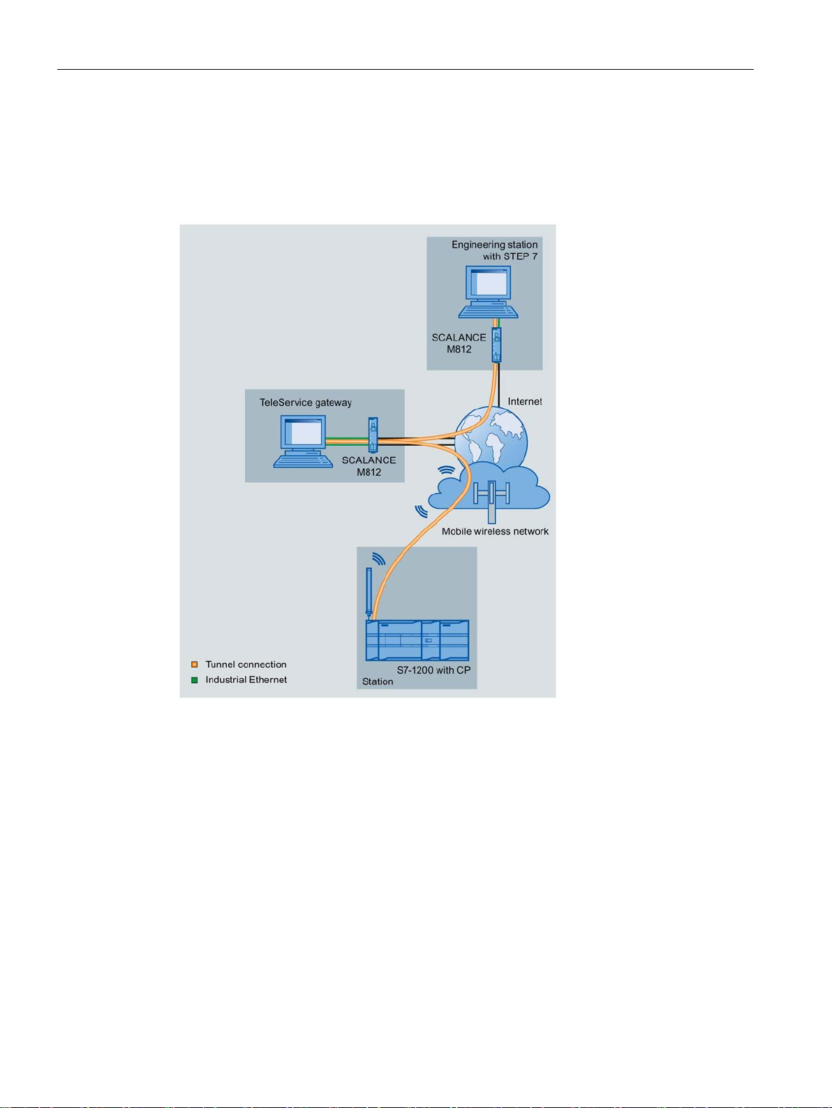
TeleService with TeleService gateway (via the Internet)
1.6 Configuration examples
The connection between the engineering station and S7 station is via the TeleService
gateway.
The engineering station is connected to the TeleService gateway via the Internet.
Figure 1-6 TeleService via the mobile wireless network with TeleService gateway - connection via
the Internet
CP 1242-7 GPRS V2
22 Operating Instructions, 10/2016, C79000-G8976-C311-02
2
2.1
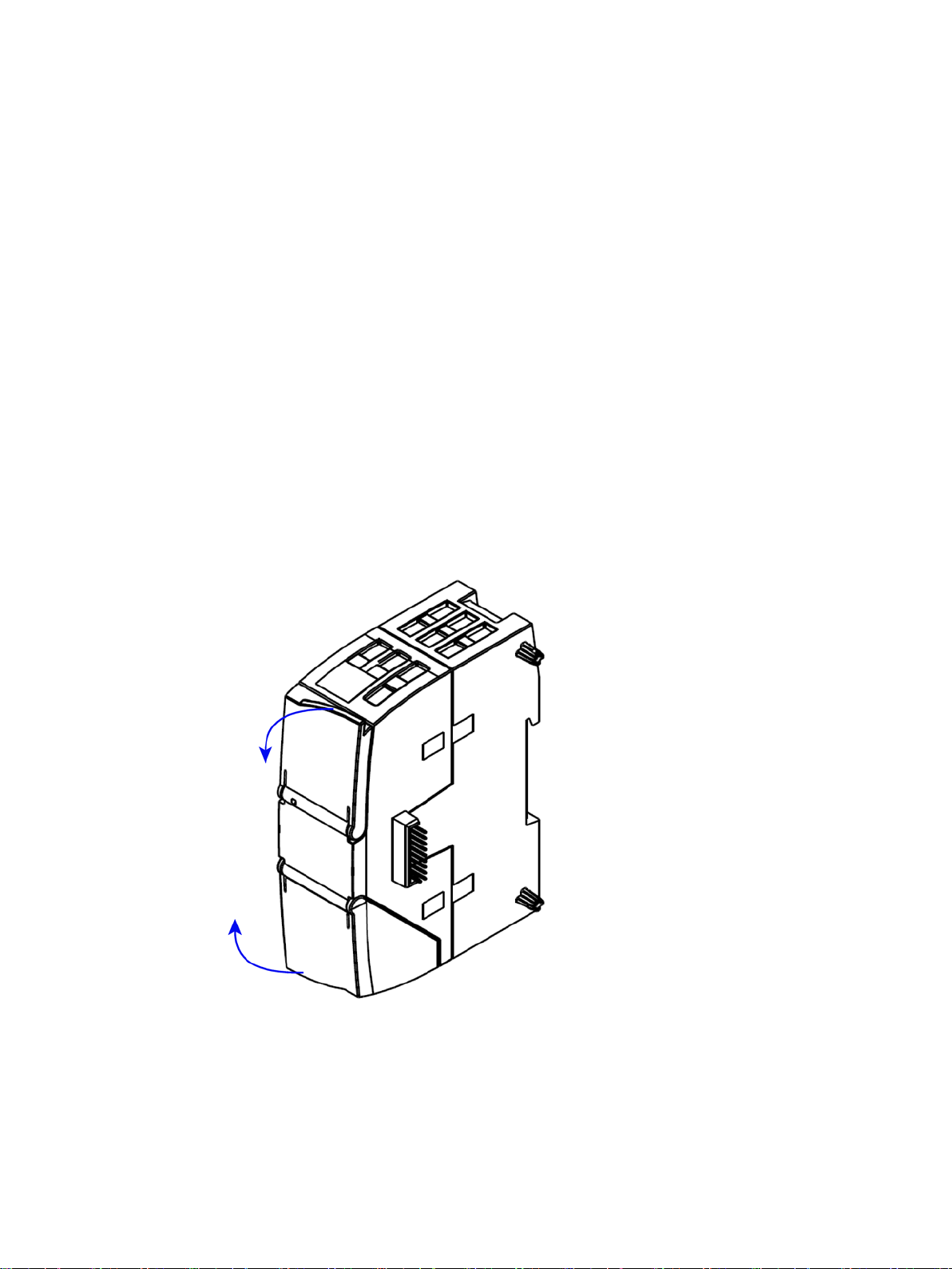
Opening the housing
Location of the display elements and the electrical connectors
Opening the housing
The LEDs for the detailed display of the module statuses are located behind the upper cover
of the module housing.
The socket for the power supply is located on the top of the module.
The connector for the external antenna is located on the bottom of the module.
Open the upper or lower cover of the housing by pulling it down or up as shown in the
illustration. The covers extend beyond the housing to give you a grip.
Figure 2-1 Opening the housing
CP 1242-7 GPRS V2
Operating Instructions, 10/2016, C79000-G8976-C311-02
23
LEDs and connectors
2.2
LEDs
LEDs of the module
LED / colors
Name
Meaning
LED / colors
Name
Meaning
red/green
green
yellow / green
green
Note
LED colors when the module starts up
When the module starts up, all its LEDs are lit for a short time. Multicolored LEDs display a
color mixture. At this point in time, the color of
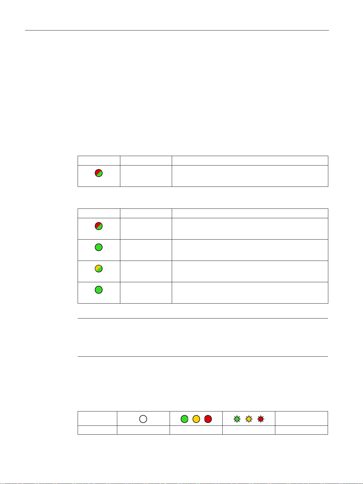
Display of the operating and communication status
Symbol
LED status
OFF
ON (steady light)
Flashing
Not relevant
2.2 LEDs
The CP has the following LEDs for displaying the status:
● "DIAG" LED on the front panel
The "DIAG" LED that is always visible shows the basic statuses of the module.
● LEDs below the upper cover of the housing
These LEDs provide further details on the module status.
Table 2- 1 LED on the front panel
red/green
Table 2- 2 LEDs below the upper cover of the housing
DIAG Basic status of the module
NETWORK Status of the connection to the mobile wireless network
CONNECT Status of the connection to the master station
SIGNAL QUALITY Signal quality of the mobile wireless network
TELESERVICE Status of the TeleService connection
the LEDs is not clear.
The LED symbols in the following tables have the following significance:
Table 2- 3 Meaning of the LED symbols
CP 1242-7 GPRS V2
24 Operating Instructions, 10/2016, C79000-G8976-C311-02
-
LEDs and connectors
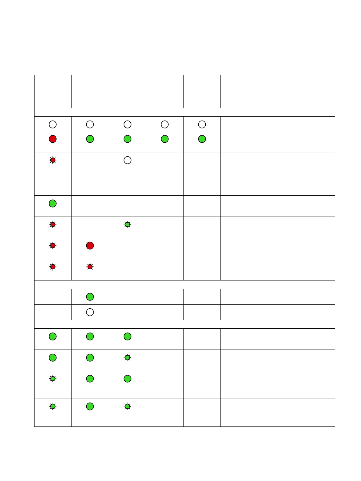
DIAG
NETWORK
CONNECT
SIGNAL
QUALITY
green)
TELE-
SERVICE
Meaning
Display of the basic statuses of the module
red
green
flashing red
flashing red
flashing red
Connection to the mobile wireless network
GSM network
Connection to communications partners
green
green
green
green
2.2 LEDs
The LEDs indicate the operating and communications status of the module according to the
following scheme:
(red / green)
flashing red
(red / green)
-
- - - - Running (RUN) without error
-
(green)
(yellow /
- - Errors:
- - Backplane bus error
- - - Missing SIM card
- - - Missing or incorrect PIN
(green)
Power OFF
Startup
• Invalid CP configuration
or
• CP type does not match the configuration
data on the CPU.
-
-
flashing
flashing
CP 1242-7 GPRS V2
Operating Instructions, 10/2016, C79000-G8976-C311-02
- - - Connection exists to the GPRS service in the
- - - No connection to the GPRS service in the
GSM network
- - Connection established to at least one partner, CPU in RUN
- - Connection established to at least one partner, CPU in STOP
- - No partner reachable, CPU in RUN
- - No partner reachable, CPU in STOP
25
LEDs and connectors
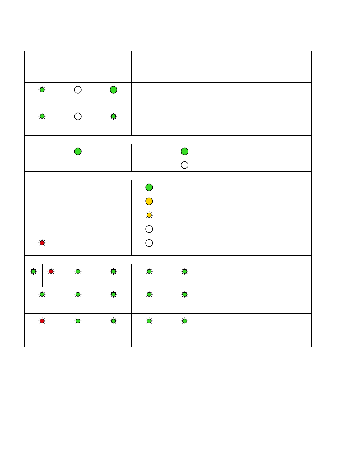
DIAG
NETWORK
CONNECT
SIGNAL
QUALITY
green)
TELE-
SERVICE
Meaning
green
TeleServiceconnection
Quality of the mobile wireless connection
flashing red
Loading firmware
green.
green
2.2 LEDs
(red / green)
flashing
green
flashing
-
- - - -
- - -
- - -
- - -
- - -
(red / green)
(green)
- -
(yellow /
- - Telecontrol configuration exists, partner not
- - Telecontrol configuration exists, partner not
(green)
reachable, CPU in RUN mode
reachable, CPU in STOP mode
TeleService connection established
No TeleService connection established
- Good network (-73 ... ≥ -51 dBm)
- Medium strength network (-89 ... -74 dBm)
- Weak network (-109 ... -90 dBm)
- No network (≤ -110 dBm)
flashing
flashing red
- -
- Missing external power supply
Loading firmware.
The "DIAG" LED flashes alternating red and
Firmware was successfully loaded.
• Error loading firmware
or
• Internal error of the CP; remedy: Power
OFF → ON
26 Operating Instructions, 10/2016, C79000-G8976-C311-02
CP 1242-7 GPRS V2
LEDs and connectors
2.3
Electrical connections
2.3.1
Wireless interface
Wireless interface for the mobile wireless network
Power supply
More detailed information on the electrical connections
2.3 Electrical connections
An extra antenna is required for communication in the mobile wireless network. This is
connected via the SMA socket of the CP. The SMA socket is located behind the lower front
cover of the CP.
You will find the antenna permitted in the section Antenna (Page 125).
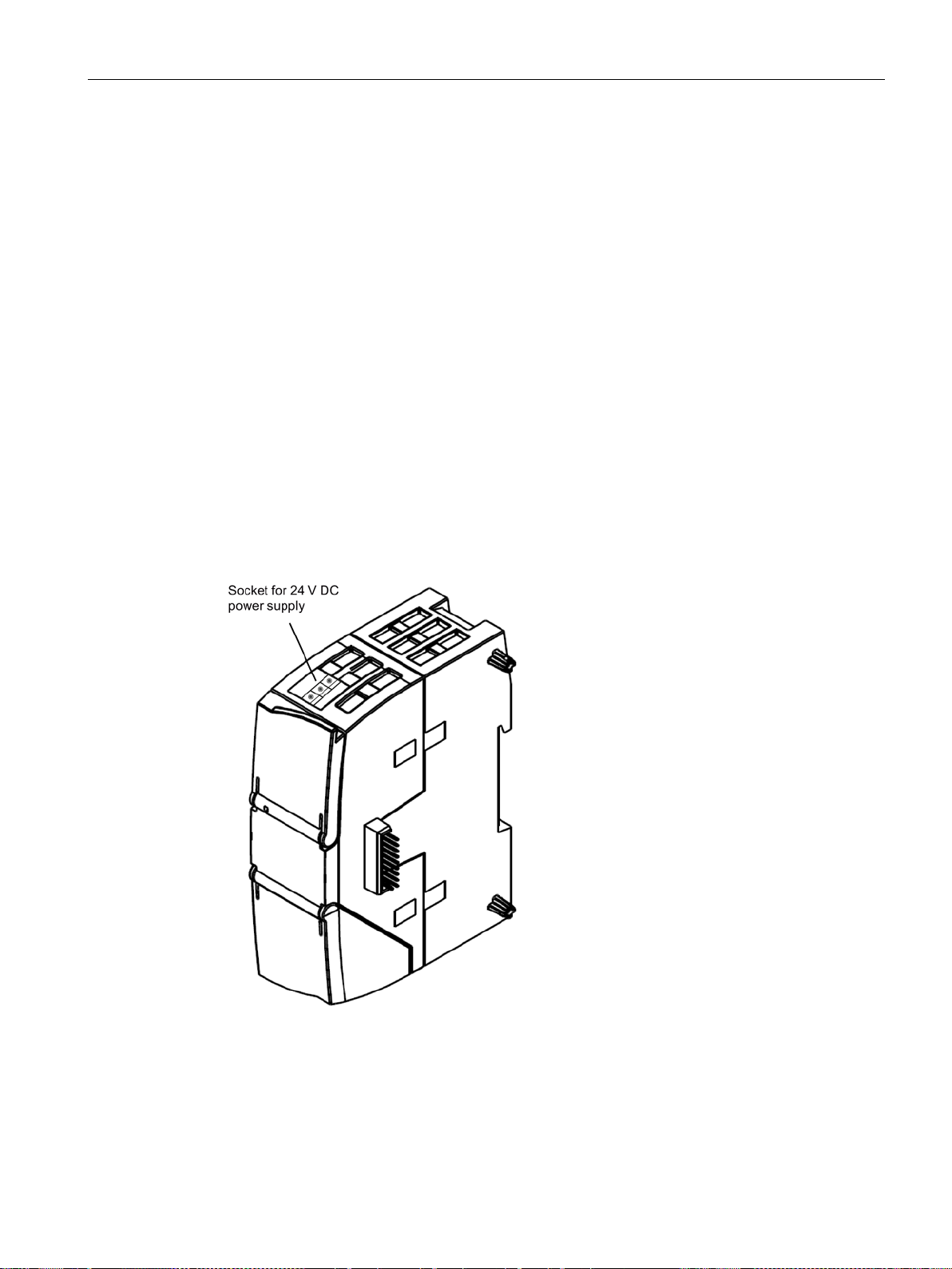
The 3-pin socket for the external 24 V DC power supply is located on the top of the module.
The matching plug ships with the product.
You will find the pin assignment of the socket in section Pin assignment of the socket for the
external power supply (Page 115).
Figure 2-2 Socket for the 24 V DC power supply
For technical information on the electrical connections, refer to the section Technical
specifications (Page 113).
CP 1242-7 GPRS V2
Operating Instructions, 10/2016, C79000-G8976-C311-02
27

LEDs and connectors
2.3 Electrical connections
CP 1242-7 GPRS V2
28 Operating Instructions, 10/2016, C79000-G8976-C311-02
3
3.1
Important notes on using the device
Safety notices on the use of the device
Overvoltage protection
NOTICE
Protection of the external power supply
3.1.1
Notices on use in hazardous areas
WARNING
EXPLOSION HAZARD
WARNING
Note the following safety notices when setting up and operating the device and during all
associated work such as installation, connecting up or replacing the device.
If power is supplied to the module or station over longer power cables or networks, the
coupling in of strong electromagnetic pulses onto the power supply cables is possible. This
can be caused, for example by lightning strikes or switching of higher loads.
The connector of the external power supply is not protected from strong electromagnetic
pulses. To protect it, an external overvoltage protection module is necessary. The
requirements of EN61000-4-5, surge immunity tests on power supply lines, are met only
when a suitable protective element is used. A suitable device is, for example, the Dehn
Blitzductor BVT AVD 24, article number 918 422 or a comparable protective element.
Manufacturer:
DEHN+SOEHNE GmbH+Co.KG Hans Dehn Str.1 Postfach 1640 D-92306 Neumarkt,
Germany
DO NOT OPEN WHEN ENERGIZED.
The device may only be operated in an environment with pollution degree 1 or 2 (see IEC
60664-1).
CP 1242-7 GPRS V2
Operating Instructions, 10/2016, C79000-G8976-C311-02
29
Installation, connecting up, commissioning
WARNING
WARNING
EXPLOSION HAZARD
WARNING
EXPLOSION HAZARD
WARNING
3.1.2
Notes on use in hazardous areas according to ATEX / IECEx
WARNING
Requirements for the cabinet/enclosure
3.1 Important notes on using the device
The equipment is designed for operation with Safety Extra-Low Voltage (SELV) by a
Limited Power Source (LPS).
This means that only SELV / LPS complying with IEC 60950-1 / EN 60950-1 / VDE 0805-1
must be connected to the power supply terminals. The power supply unit for the equipment
power supply must comply with NEC Class 2, as described by the National Electrical Code
(r) (ANSI / NFPA 70).
If the equipment is connected to a redundant power supply (two separate power supplies),
both must meet these requirements.
DO NOT CONNECT OR DISCONNECT EQUIPMENT WHEN A FLAMMABLE OR
COMBUSTIBLE ATMOSPHERE IS PRESENT.
SUBSTITUTION OF COMPONENTS MAY IMPAIR SUITABILITY FOR CLASS I, DIVISION
2 OR ZONE 2.
When used in hazardous environments corresponding to Class I, Division 2 or Class I,
Zone 2, the device must be installed in a cabinet or a suitable enclosure.
To comply with EU Directive 94/9 (ATEX95), the enclosure or cabinet must meet the
requirements of at least IP54 in compliance with EN 60529.
CP 1242-7 GPRS V2
30 Operating Instructions, 10/2016, C79000-G8976-C311-02
 Loading...