

Siemens Building Technologi es CM2N3204E / 05.2001
Landis & Staefa Divisi on 1/20
3
204
AEROGYR™
Controller
RWI65.02
for central air handling SW version 3.3
with single-speed or two-speed fans
Compact unit providing control and supervisory functions,
operating voltage AC 24 V, signal voltage DC 0...10 V.
Connection to Landis & Staefa building automation systems by means of
communication cards
In ventilating and air conditioning plants with
• hot water heating coils or electric air heater batteries
• direct expansion cooler batteries or chilled water cooling coils
• recirculated air dampers or heat recovery (HR) equipment
The RWI65.02 is used to:
• Control
– the room-supply air temperature or extract air-supply air temperature (cascade
control) with adjustable minimum and maximum limitations
– the room-supply air temperature or extract air-supply air temperature (cascade
control) with room or extract air-dependent shifting minimum and maximum
limitations (displacement ventilation)
– the supply air temperature
– the CO
2
/VOC content of the room air (demand-controlled ventilation)
– single- or two-speed fans
– air coolers
– chillers
– HR equipment
– hot water heating coils (with preheating)
– electric air heater batteries (with fan overrun)
– circulators in hot or chilled water circuits (load- or outside temperature-dependent)
– air damper actuators (with recirculated start-up circuit for modulating dampers)
– regulating units in hot and chilled water circuits
.
.
.
.
Use

CM2N3204E / 05.2001 Siemens Building Technologies
2/20 Landis & Staefa Division
• Supervise
– the air flow in air ducts
– overloads of circulators, fans and chillers
– overtemperatures of electric air heater batteries
– risk of fire or smoke
– risk of frost
– efficiency of the heat recovery equipment
Name Type reference Remarks
FLN communication card AZI65.1
1)
see data sheet 3206
LON/BACnet communication card AZI65.2
1)
see data sheet 3207
LPB communication card AZI65.3
1)
see data sheet 3208
Instructions (de, fr, it) ARG65.43
2)
included, if ordered
Instructions (en, sv, fi, no) ARG65.44
2)
included, if ordered
Instructions (nl, es, da) ARG65.45
2)
included, if ordered
Instructions (sk, hu) ARG65.47
2)
included, if ordered
1) Optional
2) Consists of operating card 2, operating instructions, and m ounting instructions
• When ordering the controller, please indicate the type reference RWI65.02. To ensure
the unit is supplied with the correct language version of the instructions, indicate the
type reference of the instructions required, e.g., ARG65.44 (for English, Swedish,
Finnish, Norwegian).
• Communication cards must be ordered separately, e.g., AZI65.1.
• Controllers and poss. communication cards are packed and supplied separately.
Name Type reference Data sheet
Temperature sensor QAA24, QAA26 1721
QAM22..., QAE21.9..., 1771, 1792
QAE22… 1771, 1792, 1791
QAD22..., QAC22, 1801, 1811
QAA64 1722
QAF63.2, QAF63.6 1821
CO
2
/VOC sensor QPA63... 1958
Processor for ventilation demand AQP63.1 1959
Remote setpoint transmitter QAA26 1721
FZA21.21, FZA61.11 3470, 3471
Signal source RVL55, 2602
PTM1.2Y10 8161
Actuator GDB161.1E; GDB163.1E 4634
GDB161.2E; GDB163.2E 4664
Automatic sensor identification (ASD logic), including type of sensor (active or passive).
Automatic activation of optimum controller configuration through ACC logic which, via
ASC, identifies the intended use of the control function. As a result, the control is
optimally matched to the plant. P-band and integral action time (TN) are separately
adjustable so that P-control (with integral action time TN = 0) or PI control can be
selected.
The controller is supplied as a PI controller. The setpoints of both heating and cooling
can be adjusted separately. Overlapping of heating/cooling sequences is not possible.
For controlling mixed air dampers or HR equipment, both the operating action and the
operating mode can be selected.
The actual values of the various outputs are permanently displayed.
Accessories
Ordering
Equipment
combinations
Technical design
Control
Siemens Building Technologi es CM2N3204E / 05.2001
Landis & Staefa Divisi on 3/20
• Room-supply air temperature or extract air-supply air temperature cascade control.
Connection of the room or extract air temperature sensors (terminal B1) and supply
air temperature sensors (terminal B2) automatically activates cascade control. With
cascade control, the room or extract air temperature is maintained at a constant level.
The room or extract air temperature represents the controlled variable whose setpoint
can be read and adjusted on the controller’s second operating level. The supply air
temperature is shifted in dependence of the deviation of the room/extract air
temperature from the setpoint of room/extract air temperature. The extent of setpoint
shift is calculated via cascade authority (adjustable from 0 to 20).
– Room supply air temperature or extract air supply air temperature cascade control
with fixed supply air limitations (mode of control 1).
If the supply air temperature drops below the limit set on the controller, the
integrated minimum limitation takes over control and prevents the supply air
temperature from dropping farther.
The set limit is maintained at a constant level. The same considerations apply to
maximum limitation.
– Room-supply air temperature or extract air supply air temperature cascade control
with shifting supply air limitations (displacement ventilation) (mode of control 2).
The shifting limits of the supply air temperature are calculated in dependence of the
actual room or extract air temperature, whereby the supply air temperature must
remain within the boundaries dictated by the selected values of minimum and
maximum limitation.
• Supply air temperature control (mode of control 3).
If a supply air temperature sensor (terminal B2) is connected, supply air temperature
control is automatically activated. With this mode of control, the supply air
temperature is maintained at a constant level.
The required mode of control can be selected.
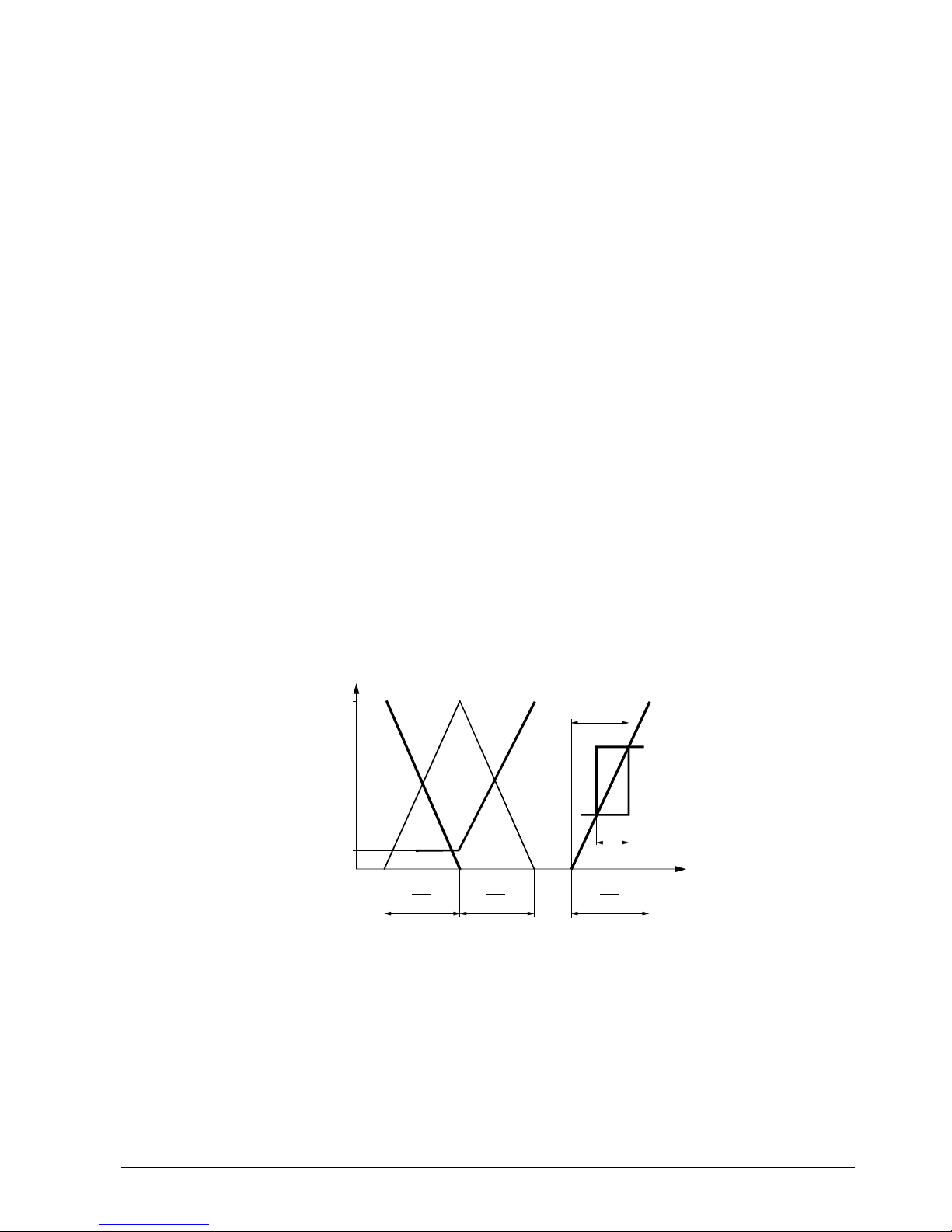
The RWI65.02 is a sequence controller with three modulating outputs (Y10 = heating,
Y20 = cooling, Y30 = HR) and one switching output (Q13/Q24 = cooling). It allows for
control sequences using both operating actions, for dampers and HR equipment. Both
operating action and control sequences are adjustable (DIL switches no. 4 to 7).
100
Y30
min
Y10
/Y30
Y30
/Y10
Y20
SA
SD
T
w
h
w
c
X
P1
T
n1
X
P3
T
n3
X
P2
T
n2
Y
[ % ]
3204D03E
(DtPnt 33)
(DtPnt 32)
(DtPnt 6)
The basis used for compensation are the setpoints selected on the controller. These
basic setpoints can be shifted as follows:
• Compensation of the controller setpoint in dependence of the outside temperature
(terminal B4); with this function, summer/winter compensation is integrated in the
controller; the compensation characteristic is adjustable
• Compensation by means of an active or passive setting unit, either as an absolute
setpoint or in the form of setpoint shifting via signal input "Z"
• Compensation across the entire setpoint range from an L&S building automation
system via the FLN bus, LON/BACnet bus or LPB bus communication card,
depending on the respective system
Temperature control
Control sequences and
operating action
Function diagram
Setpoint compensation
CM2N3204E / 05.2001 Siemens Building Technologies
4/20 Landis & Staefa Division
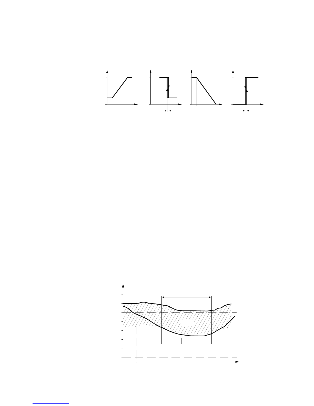
This function is intended to make optimum use of the cooling energy supplied to the
plant. Based on the measured differential of outside and room or extract air temperature, the plant is operated either with reduced amounts of outside air or with heat
recovery. The controller then overrides normal control and acts on position signal output
Y30 to position it to 100 % with HR (DC 10 V) or to Y30
min.
. This function can be
selected (DIL switch no. 3).
10
0
T
B4 < B1
B4 > B1
B4 > B1
10
0
10
0
Y30
[V]
min
Y30
min
Y30
00
B4 < B1
∆T
10
0
2 K
2 K
Y30
[V]
Y30
[V]
Y30
[V]
∆T
T
3204D02E
Mixing dampers
HR equipment
During non-occupancy periods, "Unoccupied heating mode" or "Unoccupied cooling
mode" is automatically used, provided enabling took place (can be set for each function)
and the respective preconditions are met. The factory set minimum operating time is 30
min (adjustable from 0 to 12 h).
"Unoccupied heating mode" becomes active when the set supporting level for heating
(adjustable from 0 to 30 °C) is reached. Heating is provided until the room or extract air
temperature exceeds the supporting level by 1 K. In that case, the fans run at speed I or
II (depending on the preselected speed). Outputs Y20 and Y30 with operating action " \ "
are disabled (0 %).
"Unoccupied cooling mode" becomes active when the set supporting level for cooling
(adjustable from 20 to 50 °C) is reached. Cooling is provided until the room or extract air
temperature drops below the supporting level by 1 K. In that case, the fans run at speed
I or II (depending on the preselected speed). Outputs Y10 and Y30 with operating action
" \ " are disabled (0 %).
During non-occupancy periods in the summer, this function is automatically activated if
– the function has been enabled
– both the room and the outside temperature exceed their adjusted limits, and
– the difference between room and outside temperature exceeds the set value.
If the function is activated, cool outside air is drawn into the building. In that case, the
fans run at speed I or II (depending on the preselected speed). Outputs Y10, Y20 and
Y30 with operating action " \ " are disabled (0 %). The factory set minimum operating
time is 30 min. It is adjustable (from 0 min to 12 h).
20
22
24
26
18
16
14
12
t
Nmin
T
[°C]
R/A
t
T
T
R
A
Room temperature
limit
(DtPnt 12)
Outside tem perature
limit
(DtPnt 13)
Night purging active
(DtPnt 15)
End of
occupancy time
Beginnning of
occupancy time
Delta
(DtPnt 14)
3204D04E
Maximum Economy
Changeover (MECH)
Unoccupied heating
and cooling mode
Night purging
Function diagram
Siemens Building Technologi es CM2N3204E / 05.2001
Landis & Staefa Divisi on 5/20
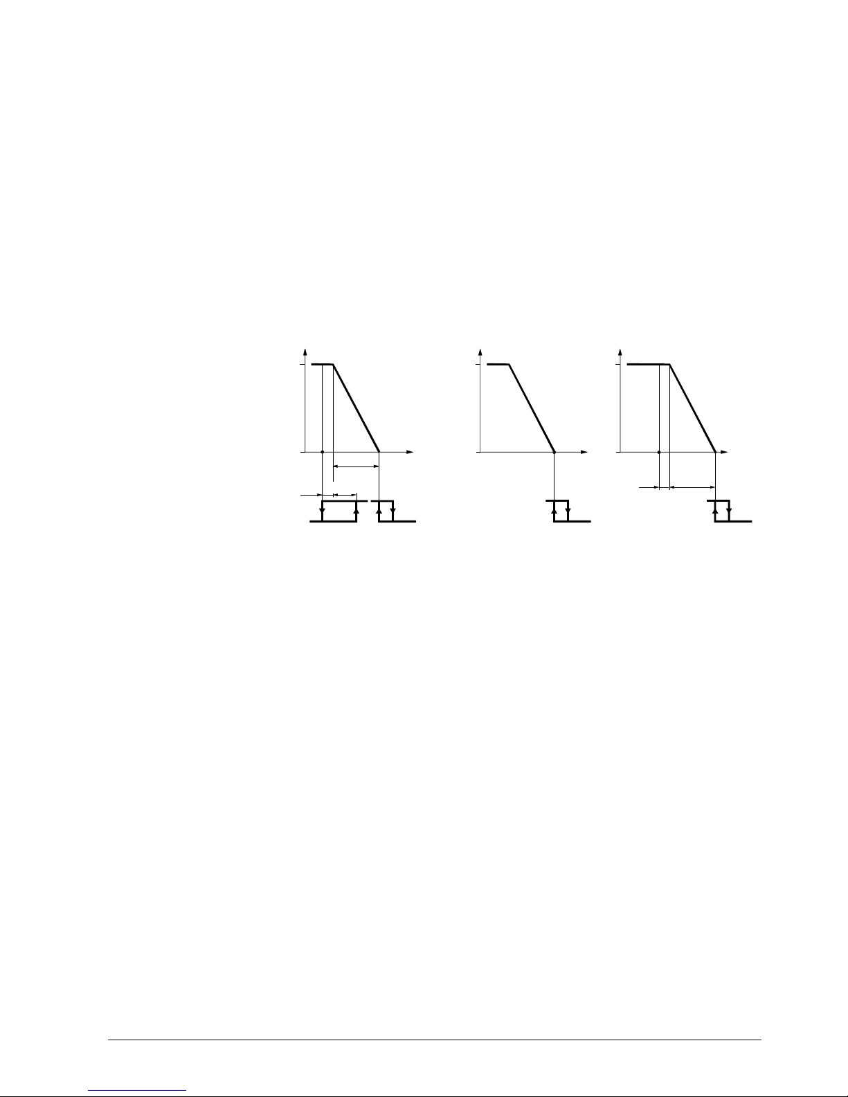
For ventilating and air conditioning plants using hot water heating coils:
All values for frost protection (response temperatures, setpoints, P-bands, and integral
action times) are preset and can be changed. The temperature is acquired either in the
water circuit or at the air outlet of the hot water heating coil.
The protective actions are the following:
• Continuous opening of the heating valve, activation of the hot water circulator
• Deactivation of the fan or closing of the air dampers
• Maintaining the temperature when the fans are deactivated (only on the water side,
setpoint "Standby controller")
• Fault status signal when there is risk of frost
Use of the following sensors is a prerequisite:
QAE21.9 or QAD22 for frost protection on the water side.
QAF63.2, QAF63.6 for frost protection on the air side.
T Temperature in the hot water heating coil’s circuit, or air temperature just after the
heating coil
Q Load
Y Manipulated variable
Y10 Control command "Heati ng val ve"
Q13/Q14 Relay output "Hot water circulator or electric air heater battery"
Q33/Q34 Relay output "Fan speed I"
Q33/Q44 Relay output "Fan speed II"
X
pd
P-band "Frost protection c ont rol l er" (data point 18)
X
pn
P-band "Standby controller" (data poi nt 19)
w
w
Frost alarm value (data point 16)
w
wn
Setpoint "Standby controll er" (data point 17)
t
Pmin
Min. running time of hot water circ ul ator (data point 48)
This function enhances comfort and optimises energy consumption in rooms with
varying occupancy levels. An integral CO
2
/VOC controller reduces the CO2 or
CO
2
/VOC concentration in the room. The P-band, the switching values for the fan
speeds, and the design value at full occupancy are adjustable; the switching differential
is 160 ppm. Using the sensors connected to signal inputs Z, B1 and B2, the controller
acquires the actual temperature and CO
2
values. If CO2 or CO2/VOC concentrations in
the room exceed the switching value of fan speed I + ½SD, the temperature controller is
activated and the fan runs at speed I. The temperature controller maintains the preselected setpoint (Comfort or Economy). If CO
2
or CO2/VOC concentrations increase
further, fan speed II is activated. Between this function and the step output of the
scheduler program, maximum value selection takes place, with both functions having
the same priority. In the case of systems with recirculated air dampers, damper control
is activated also. Here, Y30 minimum limitation, recirculated air start-up mode, and the
frost protection controller with a higher priority act on the Y30 control signal.
Frost protection
(on the water or air side)
Function diagrams
100 100
Y
[ % ]
0
0
TQ
Q33/Q34
Q33/Q44
Q13/Q14
Y10(P) Y10(PI)
Q13/Q14
100
0
T
Y10(P)
Q13/Q14
Y
[ % ]
Y
[ % ]
2 K
X
Pn
t
Pmin
t
Pmin
t
Pmin
X
Pd
½ X
Pd
2 K
w
wn
w
w
w
w
On the air
and the wate r s i de
Plant ON Plant OFF
On the air
and the water s i de
On the air side
3204D05E
(DtPnt 16)
(DtPnt 48)(DtPnt 48)
(DtPnt 17)
(DtPnt 48)
(DtPnt 18)
(DtPnt 16)
Legend
Demand-controlled
ventilation

CM2N3204E / 05.2001 Siemens Building Technologies
6/20 Landis & Staefa Division
Integral limit controller for HR equipment such as thermal wheel type heat exchangers,
plate heat exchangers, and glycol circuits: Setpoint, P-band and integral action time are
adjustable. The limit controller is active only when the plant is in operation (fan speed I
or II).
Using the sensors connected to signal inputs Z, B1 and B2, the controller acquires the
actual temperatures. The manipulated variables delivered by the integral limit and
temperature controllers are compared with one another with the help of a priority
selector which selects the manipulated variable with the smallest value (minimum
selection). This manipulated variable reduces the output of the HR equipment. Since a
certain amount of heat is not now available from the HR equipment, the balance is
delivered by a downstream air heater battery (terminal Y10).
An additional sensor must be installed if this function is used. Three temperature values
(temperature behind the heat recovery equipment, outdoor air and extract air temperatures) are required to calculate efficiency. The calculated value is shown on the controller and it generates an alarm if it falls below an adjustable threshold value.
To display data points 103 to 111, set DIL switch No. 2 to the left (ON).
The efficiency calculation acts as a fault indicator, for example, for defective, polluted or
incorrectly connected heat recovery equipment.
This function (display/alarming) is supported by the integration solutions FLN (AZI65.1 /
UNIGYR, VISIONIK) and LON/BACnet (AZI65.2 / DESIGO 30).
When this function is used, the Z-input is not available for other functions.
The start-up mode is only used with the heating sequence Y30 with operating action "/"
(plants using recirculated air dampers). On plant start-up, either supply air temperature
control or one of the two cascade control modes is activated.
The period of time for start-up mode can be set from 0 s to 60 min. During this time, the
cooling sequence (Y20) is disabled and the hot water circulator (Y10) is activated. The
plant operates with 100 % recirculated air (pre-purging).
In the case of plants that use outside sensors, this f unction becomes active only at
outside temperatures below 15 °C.
In the case of plant start-ups initiated by "Unoccupied heating mode", "Unoccupied
cooling mode" or "Night purging", this function remains inactive.
Plant operation can be controlled from the following locations:
Manual switch (operating level 1: buttons 1 to 4), communication (FLN bus), "External
switch" (E7, E8), "Extended operation" (E7, E8), scheduler program, "Demand controlled ventilation", "Unoccupied heating mode", "Unoccupied cooling mode", night
purging, fault, commissioning.
• From an external switch:
The functions of the manual switch on the RWI65.02 (operating level 1, buttons 1
to 4) can be provided by a 4-step rotary switch with two levels.
• By the function "Extended operation":
When a pulse (of at least 3 s) is fed to E7, the plant is operated at fan speed I;
When a pulse (of at least 3 s) is fed to E8, the plant is operated at fan speed II.
• Scheduler program:
The scheduler integrated in the RWI65.02 facilitates the setting of four switching
times per day; each switching time can be assigned a fan switch position (off, speed I,
or speed II) and a setpoint pair (Economy and Comfort); the settings are made on
operating level 3.
• Summer-/wintertime changeover
This function prevents freeze-up of the hot water heating coil at low outside
temperatures (especially in plants that use on/off dampers).
The period of time during which preheating is active can be adjusted from 0 s to 10 min.
When the plant is switched on, only the hot water circulator (Q13/Q14) initially is
activated while the hot water valve (Y10) is fully open.
A
nti-icing protection fo
r
HR equipment
Efficiency supervision
of the heat recovery
system
.
.
.
.
.
.
.
.
.
.
.
Start-up mode
Control
Switching the plant via
control inputs E7 and E8
Timer
Preheating time

Siemens Building Technologi es CM2N3204E / 05.2001
Landis & Staefa Divisi on 7/20
To protect the plant, fan speed II is disabled when outside temperatures are very low.
The outside temperature at which this function is activated depends on the set value
(adjustable from
−50 °C to +150 °C). To prevent the controlled system from oscillating
at greatly varying outside temperatures, the RWI65.02 operates with a fixed hysteresis
of 2 Kelvin.
This function is used in connection with outside air handling to save energy (predominantly in rooms with low occupancy levels).
The damper sequence (Y30) with operating action " / " is not implemented as a control
sequence. During plant operation, the damper is preset to a fixed position. The fixed
value of the manipulated variable for the air dampers is adjustable from 0 to 100 %
(Y30 minimum limitation).
• For the hot water pump (DIL switch no. 8 must be in position "Hot water heating coil")
To avoid damage during plant off times, there are three settings:
– The pump is activated permanently;
the pump is activated for 30 s at 24-hour intervals after the last operation, or
– The pump runs continuously when the outside temperature is below 5 °C; the
minimum pump running time (adjustable from 0 s to 30 min) is maintained
– The pump is periodically activated, i.e., the pump is activated for 30 s after the last
operation according to the selected time (adjustable from 5 min to 24 h)
• For the chilled water pump
To avoid damage during plant off times, it is possible to select periodic pump run. If
this function is enabled (selectable), the pump is activated for 30 s every afternoon at
15.00.
• Forced run-up
The fan is always started via the first speed. If the second s peed is selected right from
the start, the first speed is first activated.
Switching to the second speed takes place only when the set time has elapsed
(adjustable from 0 to 5 min).
• Rundown time
When switching down from the second to the first speed, the RWI65.02 deactivates
the second speed, and the first speed is activated only when the preset time has
elapsed (adjustable from 0 s to 5 min).
• In plants using hot water heating coils:
– Continuous checkback signals on the operational status of the plant and on the
status of the hot water circulator, based on the signals received from supervisory
elements such as flow switch and overload protection
– Continuous supervision of risk of frost
– Switching on and off depending on the selected alarm priority ("A" or "b")
• In plants using electric heater batteries:
– Continuous checkback signals on the operational status of the plant and,
especially, on that of the electric heater battery, based on the signals received from
supervisory elements such as flow switch, overload and overtemperature protection
– Switching on and off depending on the selected alarm priority ("A" or "b")
• In plants with heat recovery systems
– Continuous efficiency evaluation
• In plants using chilled water cooling coils/chillers:
– Continuous checkback signals on the operational status of the plant and on the
status of the chilled water circulator or chiller, based on the signals received from
supervisory elements such as flow switch and overload protection
– Switching on and off depending on the selected alarm priority ("A" or "b")
Disabling of fan speed II at
low outside temperatures
Fixed preset damper
position
Periodic pump run
(pump kick)
Forced run-up and
rundown time for fans
Supervision
.
.
.

CM2N3204E / 05.2001 Siemens Building Technologies
8/20 Landis & Staefa Division
The RWI65.02 is able to acquire and handle eight fault status signals from plant
elements and statuses. When the front door is closed, the signals are shown in lines 9
and 10 of the display as follows:
I,II
E6E4
E1
E2
E5
B9
E3
∆
p
10
9
A 0 b 0
3204Z01
1 2 0
1234
657 8
1 Supervision of risk of frost (signal input B9)
Display: 0 = normal, "A" or "b" = frost alarm
2 Supervision of air flow (signal i nput E2)
Display: 0 = normal, 1 = st art phase, "A" or "b" = faulty flow
3 Overload of chiller or chilled water circulator (signal input E4)
Display: 0 = Q13/Q24 cooling deacti vated, 1 = Q13/Q24 cooling activated,
"A" or "b" = cooling at fault
4 Freely available, e.g. for f i l ter supervision (signal input E6)
Display: 0 = normal, 1 = st art phase, "A" or "b" = fault at E6
5 Overload/overtemperature at hot water c i rculator or electric heater battery (si gnal i nput E3)
Display: 0 = Q13/Q14 heating deactivat ed, 1 = Q13/Q14 heating activated,
"A" or "b" = pump or electri c heater battery at fault
6 Overload of fan (signal input E5)
Display: 0 = Q33/Q34/Q44 fans deactivated, 1 = Q33/Q34 fan speed I activated,
2 = Q33/Q44 fan speed II activated, "A" or "b" = fan at fault
7 Supervision of f i re/smoke (signal input E1)
Display: 0 = normal, "A " or " b" = fire/smoke alarm
8 Heat recovery equipment efficiency supervision (s i gnal i nput Z)
display: no pointer = normal, vi sible pointer = efficiency is below the s et alarm threshold.
Depending on the priority, fault status signals are indicated by a flashing "A" or "b"
in the display (with efficiency supervision using pointer) and by a flashing red LED
located on the acknowledge button on the unit front. Depending on the priority coding of
contact output F91 ("A" and "b" or "A" or "b"), the fault status signal can also be passed
on to F91 as a common fault status signal.
For each status input, the priority of the fault status signal ("A" or "b") can be selec ted.
Each of the status inputs E1 through E6 can be matched to the type of contact of the
respective signal element (N.O. or N.C. contact).
For status inputs E2 and E6, alarm delays to prevent false alarms are also available.
Any fault displayed can be acknowledged from the acknowledgment button on the unit
front. When a fault is acknowledged, the priority display changes from flashing to steady
and the centralized fault status signal at centralized alarm output F91 is cancelled.
The display of a priority "b" fault status signal goes out when the signal is no longer
present at the fault status signal input. When no other fault status signal is present at
the fault status signal inputs, the display in the acknowledgment button changes from
red to green.
The fault status signal indications (display and acknowledgment button) for a priority "A"
fault can be cancelled by pushing the acknowledgment button again, as long as no
other fault status signals with priority "A" are present.
For the effects of the fault status signals at the outputs of the RWI65.02, refer to the
function flow diagrams on the last page of this data sheet.
Fault status signals and
signalling
.
.
.
.
.
.
.
.
.
.
.
.
.
Legend
.
.
.
.
.
.
A
cknowledging the fault
status signal
.
.
.
.
.
.
.
.
.
.

Siemens Building Technologi es CM2N3204E / 05.2001
Landis & Staefa Divisi on 9/20
The controller consists of a controller insert and the base.
The controller insert accommodates all operating elements and the electronic circuits. It
is secured to the base by two screws which are designed such that they push the insert
away from the base when loosened.
An EEPROM stores all setting values. In the event of a power failure, the setting values
are retained for an unlimited period of time. The reserve for weekly scheduling (typically
48 hours) is contained in the controller insert. As a result, the insert can be removed
from its base without affecting the actual time settings.
The base is made of plastic and is designed for both wall and flush panel mounting. In
the case of flush panel mounting, the controller is secured by a clamp. The base carries
four terminal blocks and a terminal strip for establishing the electrical connections with
the controller insert.
The RWI65.02 is operated from four operating levels: information level, setting level,
scheduler program level, and commissioning level.
When the front door is closed, the display shows the following information:
Selection of operation (black pointer), manipulated variables, temperatures, weekday,
time, and status information.
The following settings can be made (if not disabled): operating mode (Automatic, fan
speed II, fan speed I, Standby), time of day, weekday, and daylight saving or standard
time (summer- or wintertime).
I
II
B9E3E2E5E4E1E6
∆∆∆∆
P
100
0
100
19.5
17.5
12.4
1
22.45
A0b0
120
1
2
3
4
5
6
7
8
131211109
3204Z02
1
2
3
4
5
6
7
8
9
10
+1h
1...7
2
Y 30
Y 10
Y 20
I,II
I,II
T
T
Landis & Staefa
RWI65.02
T
1 Button for automatic plant operation ( )
2 Button for plant operation using fan speed 2 ( II )
3 Button for plant operation using fan speed 1 ( I )
4 Button for Standby mode (incl. fros t protection)
5 Black pointer, indicates plant operat i on selected with the manual switch (buttons 1 to 4)
6 Button for setting the current weekday (Mo = 1 .... S u = 7)
7 Button for setting the actual time
8 Black pointer, indicates that the clock is set to daylight saving (summer) time (no indi cation =
standard (winter) time)
9 Operating card 1 (for operating level 1)
10 LED (green) for indication of the plant’ s operational status (fans ON = LED lit , OFF = dark)
11 Universal button with LED (red) for indicat i on, acknowledgement and resetting of fault statuses
12 Buttons for adjustments
13 Keyhole to open the front door (key enclosed)
Mechanical design
Operation
Information level
(operating level 1)
Front door closed
Legend

CM2N3204E / 05.2001 Siemens Building Technologies
10/20 Landis & Staefa Divisi on
After opening the front door, operating card 2 can be accessed: the 10 lines of the front
page (operating level 2) show the setting and display options required for operation.
With the exception of lines 5 and 8, the values can be readjusted when operating level 2
is active.
Line 5 displays the actual setpoint of heating (black pointer).
After pressing button 5, the actual setpoint of cooling (no black pointer) is displayed.
When pressing both buttons at the top (lines 1 and 2) simultaneously for two seconds,
the scheduler program level appears. The relevant text is located on the rear of
operating card 2.
Closing the front door automatically reactivates operating level 1.
1
2
3
4
5
6
7
8
9
10
1 2
345
Max. supply air temp.
Min. supply air temp.
Running mode
Data point number
Data point value
Heating
Cooling
Cooling
Heating
Heating
Cooling
3204Z03E
Set point
Actual
Economy
Comfort
1 Front door
2 Space for operating card 1 and Operating I nstructions with normal operation data point list and
description of operating m ode di splay 1 through 10 (operating level 2, line 8)
3 Cover with operating card 2 (front: operating l evel 2, rear: operating level 3)
4 Display window with ten lines
5 Function buttons to c hange the setpoints
The DIL switches for the configuration of the RWI65.02 are located behind the cover. To
view or change settings, open the front door and remove the cover.
1
2
3
4
5
6
7
8
9
10
3204Z04
8
7
6
5
Y10 Y30
Y30
Y10 Y10
4
3
2
1
Test Run
8
7
6
5
4
3
2
1
Y30
Y30 Y10
Y30 Y30
The controller is supplied with the DIL switches set to OFF (factory settings).
The switch positions have the following meaning:
Setting level (operating
level 2) and scheduler
program level
(operating level 3)
Front door open
Legend
Configuring the unit
with DIL switches
Front door opened,
cover removed

Siemens Building Technologi es CM2N3204E / 05.2001
Landis & Staefa Divisi on 11/20
No. ON Position OFF Position
8 Electric heater battery
1)
Hot water heating coil
2)
7 Operating action Y10 " / " Operating action Y10 " \ "
6 Output Y30 disabled Output Y30 enabled
5 Comfort (first Y10, then Y30) Economy (first Y30, then Y10)
4 Operating action Y30 for mixing dampers Operating action Y30 for HR
systems
3 Without MECH function With MECH function
2 Display "Heat recovery equipment no display "Heat recovery
efficiency supervision" equipment efficiency supervision"
1 Test function for production Normal DDC operation
(cannot be used)
1) Fan overrun is automatically activated
2) Frost protection controll er i s automatically activated
The RWI65.02 can communicate with an active bus device (master) with the aid of
– the FLN (Floor Level Network) communication card AZI65.01 or
– the LON/BACnet (Local Operating Network with BACnet protocol) communication
card AZI65.02 or
– the LPB (Local Process Bus) communication card AZI65.03
each card contains the electronic circuits required for communication.
The compartment be-comes accessible after opening the front door and removing the
cover. The communication card slides into its compartment in grooves. Fitting the FLN
communication card in the RWI65.02 requires no re-commissioning, but only bus
registration for data exchange on the network.
Eighty percent of the plastic materials used can be recycled. In place of NiCd batteries,
the controller has a super capacitor which requires replacement every two years and
improves operating safety and environmental protection.
The controller requires AC 24 operating voltage. The transformer must be suitable for
safety extra-low voltage (SELV), 100 % duty, and must have separate windings.
Fuses, switches, wiring and earthing must comply with all local safety regulations.
The limitations cannot be used as safety functions. These always require separate
safety devices.
All important variables required for commissioning −if known at the time of planning−
must be indicated on the plant documentation (connection diagrams, etc.).
For additional information on the RWI65.02, please refer to the Reference Manual,
ordering no. CM2Z3204E. It contains application examples, detailed function
descriptions, a data point list for commissioning, safety notes, etc.
The controller has been designed for wall mounting (in an open space or inside a
control panel) or flush panel mounting (control panel front, console, etc.). Observe the
permissible ambient conditions. Begin by mounting and wiring the base. The cables
inside the base must be accommodated so that you can easily fit the card.
Secure fixing screws only after commissioning.
The controller is supplied complete with mounting instructions.
For commissioning, the Reference Manual, ordering no. CM2Z3204E, is required.
When commissioning the plant, check all functions of the controller and of the
communication card (if present) as well as the wiring of the connected units.
.
.
.
Communication cards
AZI65...
Recycling, environmental protection,
operating safety
Engineering notes
Fitting notes
Commissioning
notes

CM2N3204E / 05.2001 Siemens Building Technologies
12/20 Landis & Staefa Divisi on
The controller is supplied with factory set control functions and parameters. If required,
configure the RWI65.02 for various logical functions such as electric heating which is
also subject to specific safety regulations.
You can change the configuration with the help of the built-in DIL switches.
Use the function buttons on the respective operating levels to change values. Any
change is immediately saved on pressing the acknowledge button (when the display
stops flashing).
Note changed values on the rear of the operating instructions (folded sheet).
Operating voltage AC 24 V ±20 %
Safety extra-low voltage (SELV) as per EN 60 730
External transformer (100 % duty) as per EN 60 742
Fusing of supply line (external) 10 A max.
Frequency 50 Hz or 60 Hz
Power consumption 10 VA
Digital inputs E1...E8
Voltage at open input DC 20...23 V
Logic 0
<DC 1 V
Logic 1
>DC 5 V
Current at "Logic 0" 9 mA
Perm. line lengths with copper 1.5 mm
2
300 m max.
Analog inputs B1, B2, B4, B9, Z
Sensors
Passive LG-Ni1000 Ω
Active DC 0...10 V
Measuring range −50...+150 °C
Perm. line lengths with copper 1.5 mm
2
200 m max.
Setpoint transmitter
Passive 1000...1235 Ω
Active DC 0...10 V
Setting range −50...+150 °C
Perm. line lengths dep. on transmitter type
Analog outputs Y10, Y20, Y30
Output voltage DC 0...10 V
Output current
±1 mA max.
Max. load sustained short-circuit
Relay outputs Q1 3/Q14/Q24, Q33/Q34/Q44
Switching capacity, voltage AC 19 V min., 265 V max.
Switching capacity, current at AC 19 V 20 mA min., 4 A / 3 A
1)
max.
Switching capacity, current at AC 265 V 5 mA min., 4 A / 3 A
1)
max.
Relay output F91
Output voltage AC 24 V
Switching capacity, current 20 mA min., 4 A / 3 A
1)
max.
1) at c os ϕ = 0.6
Protection class III as per EN 60 730
Housing protection
When mounted on a flat wall IP 40 as per EN 60 529
When mounted in a control panel front
Casing IP 40 as per EN 60 529
Base IP 20 as per EN 60 529
Operation as per IEC 721-3-3
Climatic conditions class 3K5
Temperature −5...+50 °C
Humidity (non-condensing)
<85 % r.h.
Settings
Recommendation
Technical data
Power supply
Inputs
Outputs
Degree of protection
Environmental
conditions

Siemens Building Technologi es CM2N3204E / 05.2001
Landis & Staefa Divisi on 13/20
Transport as per IEC 721-3-2
Climatic conditions class 2K3
Temperature
−25...+70 °C
Humidity
<95 % r.h.
Mechanical conditions class 2M2
Electromagnetic compatibility
Emissions as per EN 50 081-1
Immunity as per EN 50 082-2
conformity as per
EMC directives 89/336/EEC
Low voltage directive 73/23/EEC
Product standards
Automatic electric controls
for household and similar use EN 60 730
Reserve in the event of a power failure 48 h (typical)
Connection terminals for wires 2 x 1.5 mm
2
or 1 x 2.5 mm
2
Weight (incl. packaging) 1.17 kg
GM
B1 B2
B4 B9 Z GE E1 E2 E3 E4 E5 E6 E7 E8
G0 Y10 G GY20 GY30 UP UN
AZI65...
F91 Q14 Q24 Q34 Q44
3204G01
Q13 Q33
G Operating voltage, AC 24 V (system potential)
G0 Operating voltage (system neutral)
M Measuring neutral
B1 Measuring s i gnal from the room or extract air temperat ure sensor (LG-Ni1000 Ω / DC 0...10 V)
B2 Measuring s i gnal from the supply air temperature sensor (LG-Ni1000 Ω / DC 0...10 V)
B4 Measuring s i gnal from the outside sensor (LG-Ni1000 Ω / DC 0...10 V)
B9 Measuring s i gnal from the frost sensor (LG-Ni1000 Ω / DC 0...10 V)
Z Measuring signal from peripheral devic es (LG-Ni1000 Ω / DC 0...10 V)
Y10 Control signal output for heating (DC 0...10 V)
Y20 Control signal output for cooling 1) (DC 0...10 V)
Y30 Control signal output for heat recovery (DC 0...10 V )
GE Signal voltage neutral for digital i nputs E1 through E8
E1 Digit al status input "Fire/smoke"
E2 Digit al status input "Air flow signal"
E3 Digit al status input "Overload hot water circul ator or overtemperature electric heater batt e ry"
E4 Digital st atus input "Overload of chiller or chilled water circulator"
E5 Digit al status input "Overload fan"
E6 Digit al status input, not used
E7 Digit al i nput "Control input 1"
E8 Digit al i nput "Closed input 2"
F91 Common fault status output (AC 24 V) with priority "A" and "b" or " A " or "b" (can be coded for
this output)
Q13/Q14 Potential-free relay contact output, to switch circul at or or el ectric heater battery
Q13/Q24 Potential-free relay contact output for compressor, dx-cooling or chilled water circulator 1)
Q33/Q34 Potential-free relay contact output, to switch fan speed I
Q33/Q44 Potential-free relay contact output, to switch fan speed II
UP, UN Connections (2...3) for communication
Note: LG-Ni1000 Ω sensors = L&S standard
Control signal outputs Y20 and Q13/Q24 are avai l abl e at the same time
Standards
Miscellaneous
Connection diagram

CM2N3204E / 05.2001 Siemens Building Technologies
14/20 Landis & Staefa Divisi on
Wiring diagram 1: Measuring part for temperature with passive main and auxiliary
sensors
G
G
B1
B1
3204A01
BM
B2 B3 B4
MB4B9
G0
N1
G0
MMMBBB
B2MMM
AC 24 V
Wiring diagram 2: Measuring part for temperature with active frost sensor and with
outside temperature acquisition via RVL55
G
G
B1
B1
3204A02
BM
B2 N2 B5
MB4B9
G0
N1
G0
MMMB
U4
B
B2MMM
AC 24 V
G
Wiring diagram 3: Measuring part with active remote setting unit
G
G
3204A03
R1
G0
N1
G0
Y9
Z
AC 24 V
G G0
G0
Wiring diagram 4: Measuring part with passive remote setting unit
G
G
3204A04
R2
Z
G0
N1
G0
MR
M
AC 24 V
B
B1
Wiring diagram 5: Measuring part with extract air temperature sensor for limit control
(anti-icing protection with HR)
G
G
3204A08
B6
Z
G0
N1
G0
MB
M
AC 24 V
Wiring diagrams
Connections on the
measuring side

Siemens Building Technologi es CM2N3204E / 05.2001
Landis & Staefa Divisi on 15/20
Wiring diagram 6 and 7: Measuring element with CO2/VOC sensor with or without
ventilation demand processor for demand-controlled ventilation
G
G
G0
U
G0
U1M
AC 24 V
U2
G
(CO2) (VOC)
U1
M
B7
G
G0
G1 U2
S
M Z
N1
3204A09
10
U3
M
D
G
G
3204A10
G0
N1
G0
U1M
AC 24 V
U2
G
(CO2) (VOC)
ZM
B7
N1 Controller RWI65.02
N2 RVL55 with plug-in module AZY 55. 60
B1 Room or extract air temperature sensor QAA24/QAM22...
B2 Supply ai r temperature sensor QAM22...
B3 Outs i de temperature sensor QAM22.../QAC22
B4 Tem perature sensor QAD22/QAE21.9...
B5 Frost sensor QAF63.2/QAF63.6
B6 Extract ai r temperature sensor QAM22...
B7 CO
2
/VOC sensor QPA63...
R1 Remote setting unit FZA61.11
R2 Room unit QAA26 or set poi nt transmitter FZA21.21
S On/Off switch "Locking signal"
U Ventilation demand processor AQP63.1
Wiring diagram 8: Control part with regulating units for heating, cooling and HR
G
G
G0 Y10
GY
G0
Y20 Y30
G0
N1
Y1 Y2 Y3
3204A05
AC 24 V
GGGG0G0G0
GY
G0
GY
G0
N1 Controller RWI65.02
Y1 Regulati ng uni t for heating
Y2 Regulati ng uni t for cooling
Y3 Regulati ng uni t for HR/recirculated air dampers
Wiring diagram 9:
GE E1 E2 E3 E4 E5 E6
Q44
Q13 Q33
Q34
3204A06
T
Dp
F91
L
H1 K3 K4
N1
AC 230 V
AC 24 V
F3
F3
Auto
0
I
II
E7 E8
Q24
F2
Q14
F1
K2
K1
S1
G
G0
F2F1
N
G
G0
K4
K3
F4
F4
N1 Controller RWI65.02
F1...F4 Overload relay contact
H1 Auxiliary unit for common fault signal
K1 Motor contactor for hot water pump or contactor for el ectric heater battery
K2 Motor contactor for chilled water circulator or chiller
K3 Motor contactor for fan speed I
K4 Motor contactor for fan speed II
Legend for wiring
diagrams 1 to 7
Connections on the
control side
Legend
Connections on the
control and
supervision side
Legend

CM2N3204E / 05.2001 Siemens Building Technologies
16/20 Landis & Staefa Divisi on
Data point values and measured values can be called up under certain data point
numbers.
The controller is supplied with factory set values (bold print). These factory settings are
selected so that the controller suits a majority of plants.
Each of them can be changed, if required. The factory set data are stored in non-volatile
memory.
No. Description Range Factory setting
1 B9 Frost temperature −50.0...+150.0 °C (Read value)
2 Z Input variable
−50.0...+150.0 °C/ (Read value)
0...2000 ppm
3 F91 Common fault relay OFF/On (Read value)
4 E7 Control input 1
1)
OFF/On (Read value)
5 E8 Control input 2
1)
OFF/On (Read value)
6 Y30 Minimum limitation 0...100 %
0 %
7 Fan speed 1/2 1
8 Setpoint pair (Comfort/Economy) Co/Ec Co
9 Room temperature limit heating 0...30 °C 15 °C
10 Room temperature limit cooling 20...50 °C 30 °C
11 Minimum operating time 00.00...12. 00 hh. mm 00.30 hh.mm
12 Room temperature limit 10...50 °C 22 °C
13 Outside temperature limit 5...30 °C 12 °C
14 Delta 1...20 K 5 K
15 Minimum operating time 00.00...12. 00 hh. mm 00.30 hh.mm
16 Frost alarm value 2...30 °C 5 °C
17 Standby controller 2...50 °C 25 °C
18 P-band frost protection controller 1...30 K 5 K
19 P-band standby controller 1...200 K 7 K
20 TN standby controller 00.00...10.00 mm. ss 03.00 mm.ss
21 Disabling of fan s peed 2 ac c .
to outside temperature B4
14)
−50...+150 °C −−−−15 °C
22 Delta for heating 1...10 K 4 K
23 Delta for cooling 1...10 K 3 K
24 KE room (cascade authority) 0...20.0 2.0
25 TN 00.00...40.00 mm.ss 08.00 mm.ss
26 P-band heating 1...200 K 20 K
27 TN heating
2)
00.00...10.00 mm.ss 02.30 mm.ss
28 P-band heat recovery 1...200 K 15 K
29 TN heat recovery
2)
00.00...10.00 mm.ss 02.00 mm.ss
30 P-band cooling 1...200 K 15 K
31 TN cooling
2)
00.00...10.00 mm.ss 02.00 mm.ss
32 Switching interval SA 1...100 % of Y20 20 %
33 Switching differential SD 1...100 % of Y20 10 %
34 Starting point 10...50 °C 25 °C
35 End point 10...50 °C 30 °C
36 Delta −10...+10 K 2 K
37 Starting point −30...+20 °C 5 °C
38 End point −30...+20 °C −20 °C
39 Delta −10...+10 K 1 K
40 E1 Fire/smok e A / b A
41 E2 Air flow supervision A / b A
42 E3 Overload pum p/electric A / b A
43 E4 Overload c hiller A / b A
44 E5 Overload fan A / b A
45 E6 AUX, freely available A / b A
46 B9 Frost alarm A / b A
47 Fan overrun ti m e
3)
00.00...30.00 mm.ss 05.00 mm.ss
48 Min. heat ing c irc ulat or running time
11)
00.00...30.00 mm.ss 05.00 mm.ss
49 Heating circulator kick interval
10)
00.00...24.00 hh.mm/
Auto/Cont
Auto
50 Alarm delay air flow start
12)
00.00...10.00 mm.ss 00.20 mm.ss
51 Alarm delay air flow operation
12)
00.00...10.00 mm.ss 00.10 mm.ss
52 Alarm delay AUX
12)
00.00...05.00 mm.ss 00.00 mm.ss
53 E7, E8 cont rol input on t i m e 4) 00.00...12.00 hh.mm 00. 00 hh.mm
54 Start-up t im e (dam per f ully closed)
5)
00.00...60.00 mm.ss 00.00 mm.ss
55 Preheating time 00.00...10.00 mm.ss 00.00 mm.ss
56 Power up start delay
13)
00.00...30.00 mm.ss 00.00 mm.ss
57 Setpoint −10...+30 °C 1 °C
58 P-band 1...100 K 10 K
59 TN
2)
00.00...04.00 mm.ss 01.00 mm.ss
Data point list for
normal operation
Current measured values
Limitation manipulated variable
Presettings
Unoccupied heating/c ooling
mode
Night purging
Setpoints frost
protection/ sta ndby cont roller
Parameters frost
protection/ standby
controller
Displacement ventilation
Control paramete rs room
temperature controller
Control paramete rs supply air
temperature controller
Switching points compressor
Summer compensation
Winter compensation
Alarm priorities
Time elements
HR anti-icing prot e c t ion

Siemens Building Technologi es CM2N3204E / 05.2001
Landis & Staefa Divisi on 17/20
60 Switching value fan speed I 500...1800 ppm 700 ppm
61 Switching value fan speed I I 500...1800 ppm 1200 ppm
62 Design v alue f ull oc c upanc y 500...1800 ppm 1000 ppm
63 P-band 100...800 ppm 400 ppm
64 Hours run counter
9)
0...9999 x 10 h (Read value)
65 Operation lock
6)
OFF/On OFF
66 RW I software version
7)
"00.00" (Read value)
67 Communication address
8)
----,0...126 - - - -
68 Segment number 0...14 0
69 Device no. for supplier holiday program 0...16 0
70 Segment no. for supplier holiday program 0...14 0
71 Supplier clock time 0...2 0
72 Bus supply 0/1 1
73 Outside t em p. on m in. heating demand −35...+ 35 °C 20 °C
74 Minimum heat ing dem and 0...100 °C 40 °C
75 Outside t em p. on m ax. heating demand −35...+35 °C −
−−
−15 °C
76 Maximum heat ing dem and 0... 100 °C 60 °C
77 Current heating demand 0...100 °C (Read value)
78 Release cooling
15)
−50...+150 °C 14 °C
103 Efficiency measurement enabled OFF/ On OFF
104 Selection of the measurement setup 1/2 1
105 Alarm delay 00.00...10.00 hh.mm 00.10 hh.mm
106 Alarm priority A/b b
107 Disable above outside air temp. −35...+35 °C 15 °C
108 Correction of fan influence 0,0...5 K 0,5 K
109 Alarm threshold 0...100 % 50 %
110 Measured value −50...+ 150 °C (Read value)
111 Efficiency 0...100 % (Read value)
1) Indicates whether input E7, E8 is open or closed (control signal "yes" or "no")
2) Integral action time (Tn) = 0 s means: P-control for the respective control sequence
Integral action time (Tn) > 0 s means: PI-control for the respect ive control sequence
3) Only when the RWI65.02 is configured for an electric air heater battery.
During the overrun time, the fan runs at speed I. On completion of the selected overrun time, the fans
are switched off and the outside air dampers closed
4) Period of time during which the plant - after arrival of a pulse (> 2 s) at E7 or E8 - shall operat e.
When set to 0 min, the plant is switched on or off the moment the signal arrives at E7 and E8 (external
scheduler) (only in Automatic mode and when the internal scheduler has switched off or is permanently
deactivated)
5) Period of time during which the plant may operate with 100 % recirculated air (after plant start-up)
6) If operating level 1 is locked (data point value = On), it is not possible to change any values for t wo
minutes after closing the front door (except i on: daylight s aving/standard time changeover).
Enabling by reopening the front door
7) The display shows the actual program number (software version)
8) Must be set if the controller is equipped with a communication m odule.
If no communication module is used, the value set has no effect on the RWI65.02
If the RWI65.02 is equipped with the AZI65.3 LPB communication card, the comm unic ation address
becomes the LPB device number with a range of 0 to 16 and a factory setting of 0.
If the
RWI65.02 is equipped with the AZI65.1 FLN communication card, the valid address range
is 33 to 126.
9) Counted are the number of fan operating hours.
The reading can be reset either to zero or to the former value. Proceed as follows:
1. Press function button 10 (line 10)
2. Press setting button "
−" if the meter is to be reset to zero, or setting button "+" if the meter is to be
reset to the former value
3. To confirm resetting, press function button 10 again.
10) Ac tive only if coded for hot water heating coil!
00.00
ð Circulator kick interval is disabled
00.05 - 24.00
ð Circulator kick occurs for 30 s according to the selected interval time
Auto
ð Circulator is activated for 30 s every 24 h, or runs continuously when the
outside temperature is < 5 °C; the minimum circ ulat or running time (data
point 48) is maintained
Cont
ð Circulator continuously on
11) The setting of a minimum running time avoids too frequent ac tivation/deactivation of the c irculator
12) To avoid unnecessary faulty alarms, the fault status s ignal c an be delayed
13) Af ter a power failure and subsequent power restoration, it may be necessary to bring the controller back
into operation with a certain delay. This is to make certain that after a power failure, all plant elements
connected to the same mains network are not switched on at the same tim e (peak loads)
14) To protect the plant, the second fan speed is disabled at very low outside temperatures. In that case,
only the first fan speed is enabled. To avoid unneces s ary fan s peed changes when outside
temperatures greatly vary, a hysteresis of 2 K is us ed
15) The cooling signal is released above the set outs ide air t em perat ure value. In order to avoid sliding on
changing outside temperatures, a hysteresis of 1 K has been integrated.
Demand-controlle d v e nt ilation
Miscellaneous
For LPB
Heating curve for heating
demand
Efficiency supervision
(heat recovery system)
.
.
.
.
.
.
.
Explanations

CM2N3204E / 05.2001 Siemens Building Technologies
18/20 Landis & Staefa Divisi on
Q13
Q14
Q13
Q24
Q33
Q34
Q33
Q44
Y10 Y20 Y30
I/O
A
B
A
B
E1
E2
A
B
A
B
E3
A
B
A
B
E4
A
B
A
B
E5
A
B
A
B
E6
A
B
A
B
A
B
B9
Green
LED
Red
LED
Fault
reaction
Explanation
Heat
source
Fire/
smoke
Water
Water
Electr.
Electr.
Faulty flow
Water
Water
Electr.
Electr.
Overcurrent
hot water
circulator
Water
Water
Electr.
Electr.
Overload
el-heater
Water
Water
Electr.
Electr.
Overload
fan
Water
Water
Electr.
Electr.
AUX
Water
Water
Electr.
Electr.
Water
Water
Risk of frost
Overload chiller/
chilled water
circulator
Dark Off/interlocked
Lit
Flashing Off/interlocked (switch-off delayed)
On/delocked
On/delocked when Y10 ≥ 0 %
Off/interlocked when Y10 ≥ 0 %
Dark (Y10 ≥ 0 %)
3204Z05E
Function flow
diagrams for fault
status signals
Incoming fault status
signals

Siemens Building Technologi es CM2N3204E / 05.2001
Landis & Staefa Divisi on 19/20
Acknowledged
present fault status
signals
Q13
Q14
Q13
Q24
Q33
Q34
Q33
Q44
Y10 Y20 Y30
I/O
A
B
A
B
E1
E2
A
B
A
B
E3
A
B
A
B
E4
A
B
A
B
E5
A
B
A
B
E6
A
B
A
B
A
B
B9
Green
LED
Red
LED
Fault
reaction
Heat
source
Water
Water
Electr.
Electr.
Water
Water
Explanation
Fire/
smoke
Faulty flow
Overcurrent
hot water
circulator
Overload
el-heater
Overload
fan
AUX
Risk of frost
Water
Water
Electr.
Electr.
Water
Water
Electr.
Electr.
Water
Water
Electr.
Electr.
Water
Water
Electr.
Electr.
Water
Water
Electr.
Electr.
Overload chiller/
chilled water
circulator
Dark Off/interlocked
Lit
Flashing Off/interlocked (switch-off delayed)
On/delocked
On/delocked when Y10 ≥ 0 %
Off/interlocked when Y10 ≥ 0 %
Dark (Y10 ≥ 0 %)
3204Z06E

CM2N3204E / 05.2001 Siemens Building Technologies
20/20 Landis & Staefa Divisi on
R
1
2
4.
3
145
272,5
2619
58
106,5
26 2613,5
137
5,5
5
,
5
63
152,6
144
17,5 10
30 30
133
2,5 106,5 24 30,3
Pg 11
max. R2
138
+ 1
0
138
+ 1
0
3204M01
1919
3426
5353
66
Dimensions
1999 Siemens Building Technologies Ltd.
Dimensions in mm
Panel cutout
 Loading...