

Page 1
Installation Instruct ions
1
2
9
10
1
4
3
6
4
1
3
6
2
1
1
2
7
8
Model RNI
Remote Network Interface
INTRODUCTION The Model RNI from Siemens Industry, Inc., allows for
the remote installation of the PMI/PMI-2/PMI-3, Global
PMI/PMI-2/PMI-3 (on XNET), SSD-C-REM (on HNET),
and the LVM/LCM-8/SCM-8/FCM-6/SIM-16/OCM-16
(on CAN) modules. When used in a REMBOX4, the
FMT and LVM are also supported.
The HNET/XNET can be wired either Style 4 or Style
7. The RNI must be placed in between two NIC-Cs
when used in a Style 7 Network with the Global PMI/
PMI-2/PMI-3 (on XNET) or the SSD-C-REM (HNET).
When using the PMI/PMI-2/PMI-3, the RNI may be
located in the middle or at the end of the HNET. Refer
to the table below for the allowable locations of
modules at the end of a HNET or XNET.
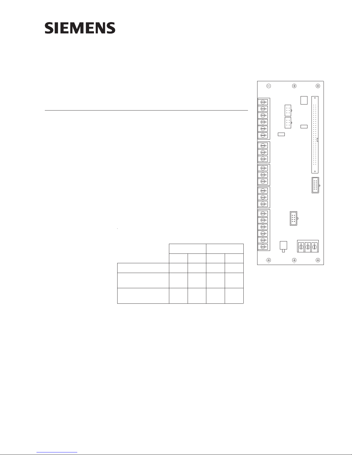
TB6
TB5
TB4
TB3
P6
P4
P3
X
H
OFF
P7
P5
ON
JP1
P1
RNI
P2
afodnEehttatnemecalPeludoM
krowteNTENXroTENH
TENHTENX
TB2
24 V
S1
TB1
4elytS7elytS4elytS7elytS
MER-C-DSSYN**
3-IMP/2-IMP/IMP
)TENH(
)TENX(3-IMP/2
YY* *
-IMP/IMPLABOLG
**YN
krowtensihtnodewollatoN*,dewollA=Y,dewollatoN=N
Figure 1
RNI Remote Network
Interface
The CAN network may only be wired Style 4. The RNI may be located at the end or in
the middle of a CAN network. A 24VDC input is also required. This can be obtained
from the PSC-12 power limited output (TB3) or any 24 VDC UL/ULC regulated, power
limited power supply listed for fire protective signaling use. Audio signals for the LVM
and FMT are connected to TB1 of the PSC-12.
The RNI mounts in the rear of either the REMBOX2 or REMBOX4 enclosures. It can
also be installed in a CAB1, CAB2, or CAB3 using the mounting plate RNI-CAB-BRKT.
The RNI provides terminal blocks for all field wiring connections. Internal connections
are made to plug in connectors specifically provided for each of the installed modules.
The HNET/XNET and the CAN networks can be used simultaneously.
P/N 315-033420-13
Building Building
Building
Building Building
Siemens Siemens
Siemens
Siemens Siemens
TT
ecec
hnologies Dihnologies Di
T
ec
hnologies Di
TT
ecec
hnologies Dihnologies Di
IndustryIndustry
Industry
IndustryIndustry
visionvision
vision
visionvision
,,
Inc. Inc.
,
Inc.
,,
Inc. Inc.
Page 2
+
–
PRE-INSTALLATION P7 enables or disables an audible device similar to the CSB. This audible sounds
whenever a switch is pressed on either the LVM, SCM-8 or the FCM-6. If this is not
desired the audible can be silenced by changing the jumper installed on P7 to
positions 2 and 3. P7 is configured in the factory (positions 1 and 2) to have the
audible active.
S1 is used to terminate the HNET/XNET. If the RNI is installed at the end of an HNET
network, S1 must be set to the ON position. If the RNI is in the middle of the HNET/
XNET, set S1 to the OFF position.
P5 must be set to the HNET (H) position to select HNET or the XNET (X) position to
select XNET. Only one network, either HNET or XNET, can be used.
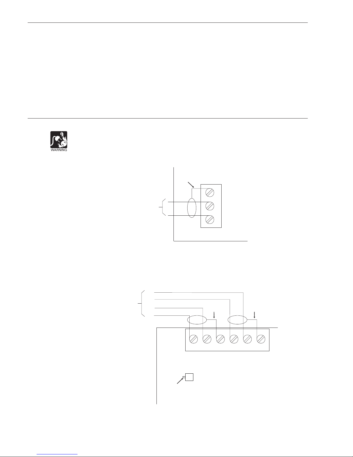
INSTALLATION
Remove all system power before installation, first battery then AC. (To power up,
connect the AC first, then the battery.)
RNI
SHIELD
NOTES:
1. 14-18 AWG.
2. 2A max. input current.
3. Supervised
4. Refer to PSC-12/PSX-12
Installation Instructions,
P/N 315-033060 for
connection to TB3 and
ground fault detection
impedance.
NOTES:
1. No EOLR required.
2. 18 AWG min., 14 AWG max.
3. 2000 feet max. per pair.
4. Use twisted pair (Style 4/7)
or twisted shielded pair
(Style 4 only).
5. Power limited to NFPA 70
per NEC 760.
6. Refer to NIC-C Installation
Instructions, P/N 315033240 for connection of
A and B pairs and ground
fault detection impedance.
7. Omit B pair for Style 4.
8. All wiring supervised.
TO PSC-12 TB3
OR ANY UL/ULC
REGULATED,
POWER LIMITED
POWER SUPPLY
LISTED FOR FIRE
PROTECTIVE
SIGNALING USE
S3
24 V
–
2
1
+
TB1
Figure 2
Connecting The 24VDC Input
B+
FROM
NIC-C
B–
A+
A–
SHIELD
SHIELD
TB2
5
B+
6
S
PRESS
DOWN
1
A–
S1
2
A+
SET TO ON
4
3
B–
S
RNI
Figure 3
Connecting HNET/XNET At The End Of The Network (Style 4 and Style 7)
(HNET PMI/PMI-2/PMI-3 Only For Style 7)
Siemens Industry, Inc.
Building Technologies Division
P/N 315-033420-132
Page 3
SHIELD
1
4
3
6
4
1
3
6
P3 P4
CAN +
CAN –
SHIELD
FROM
PSC-12
TB1
1
C+
2
C–
CCL (SUPPLIED WITH THE RNI)
3
S
4
C+
5
C–
6
S
RNI
TB6
DO NOT
USE
DO NOT
USE
1
2
3
4
5
6
7
8
9
0
1
2
3
4
5
6
7
8
9
0
LCM-8
OR
SCM-8
INSTALL
CAN TERMINATOR
P/N 110-134215
(SHIPPED WITH NIC-C)
MOUNT TO ID-MP
ON INNER DOOR
OF REMBOX2/4
†
†
NOTES:
1. No EOLR required.
2. 18 AWG min., 14 AWG max.
3. 2000 feet max. per pair
between NIC-Cs.
4. Use twisted pair (Style 4/7)
or twisted shielded pair
(Style 4 only).
5. Power limited to NFPA 70
per NEC 760.
6. Refer to NIC-C Installation
Instructions, P/N 315033240 for connection of
A and B pairs and ground
fault detection impedance.
7. Omit B pair for Style 4.
8. All wiring supervised.
B+
B–
A+
A–
FROM
NIC-C
OR RNI
B+
B–
SHIELD
A+
A–
TB2
5
B+
RNI
6
S
PUSH
UP
1
A–
S1
2
A+
SET TO OFF
4
3
B–
S
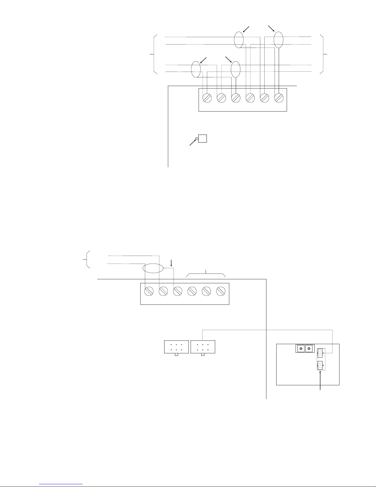
Figure 4
Connecting HNET/XNET In The Middle Of The Network (Style 4 and Style 7)
TO NEXT
NIC-C
OR RNI
NOTES:
1. 18 AWG min., 14 AWG max.
2. 15 ohms max. for CAN
network.
3. Use twisted pair or twisted
shielded pair.
4. Power limited to NFPA 70
per NEC 760.
5. Refer to NIC-C Installation
Instructions, P/N 315033240 for connection of
CAN–, CAN+.
6. Only 1 SCM-8 shown. SCM8, LCM-8, FCM-6, OCM-16,
SIM-16 all allowed.
7. All field wiring supervised.
8. Refer to PSC-12 Installation
Instructions, P/N 315033060 for ground fault
detection impedance.
Siemens Industry, Inc.
Building Te chnologies Division
Figure 5
Connecting CAN At The End Of The Network
P/N 315-033420-133
Page 4

FROM
PSC-12
TB1
CAN –
CAN +
NOTES:
1. 18 AWG min., 14 AWG max.
2. 15 ohms max. for CAN
network.
3. Use twisted pair or twisted
shielded pair.
4. Power limited to NFPA 70
per NEC 760.
5. Refer to NIC-C Installation
Instructions, P/N 315033240 for connection of
CAN–, CAN+.
6. Only 1 SCM-8 shown.
SCM-8, LCM-8, FCM-6,
OCM-16, SIM-16 all allowed.
7. All field wiring supervised
8. Refer to PSC-12 Installation
Instructions, P/N 315033060 for ground fault
detection impedance.
SHIELD
SHIELD
CAN +
CAN –
TB6
6
5
4
3
2
1
S
C–
C+
S
C–
C+
CCL*
3
1
4
6
3
1
4
6
P3 P4
RNI
CCL*
*ONLY 1 CCL, P/N 599-634214 IS SUPPLIED WITH THE RNI
Figure 6
Connecting CAN In The Middle Of The Network
TO NEXT
RNI
†
0
0
1
1
9
9
2
2
8
8
3
3
7
7
4
4
6
6
5
5
†
LCM-8
OR
SCM-8
MOUNT TO ID-MP
ON INNER DOOR
OF REMBOX2/4
NOTES:
1. 18 AWG min., 14 AWG max.
2. 15 ohms max. per pair.
3. Use twisted shielded pair for
LVM microphone and
monitor speaker.
4. Use twisted pair or twisted
shielded pair for phone.
5. Power limited to NFPA 70
per NEC 760.
6. Microphone and phone
circuits are supervised.
7. Monitor speaker is NOT
supervised.
8 Refer to LVM Installation
Instructions, P/N 315-034090.
9. Refer to FMT Installation
Instructions, P/N 315-034100.
10. No End Of Line devices
required.
11. Refer to PSC-12 Installation
Instructions, P/N 315033060 for ground fault
detection impedance.
Figure 7
Connecting The LVM and FMT
Siemens Industry, Inc.
Building Technologies Division
P/N 315-033420-134
Page 5

The RNI mounts on studs in the rear of either the REMBOX2 or the REMBOX4. Four
#8/32 nuts are provided with the RNI. (Refer to the REMBOX2/REMBOX4 Installation
Instructions, P/N 315-033772.) For Global PMI/PMI-2/PMI-3 applications the RNI can
also be installed in a CAB1/CAB2/CAB3 using mounting plate, RNI-CAB-BRKT, P/N
500-650062. (Refer to RNI-CAB-BRKT Installation Instructions, P/N 315-050062.)
Install the RNI with the terminal blocks facing up to allow for easier connection of the
field wiring.
Connecting PMI/PMI-2/PMI-3 A 40 inch long 60 wire cable, P/N 555-133743 (shipped with the PMI/PMI-2/PMI-3),
connects the RNI to the PMI/PMI-2/PMI-3. Connect one end of the cable to JP1 on
the RNI and the other end of the cable to either JP3 on the PMI or J2 on the PMI-2/
PMI-3. Be sure that the PMI/PMI-2/PMI-3 address agrees with the ZEUS configuration. Refer to the PMI Installation Instructions, P/N 315-033070, the PMI-2 Installation
Instructions, P/N 315-050636, or the PMI-3 Installation Instructions, Document ID
A6V10446194.
Connecting The Optional Connect the HTSW-1 (required for UL1076) to P6 on the RNI using the connector
HTSW-1 Tamper Switch supplied with HTSW-1. Refer to the REMBOX Installation Instructions, P/N 315-
033772 and the HTSW-1 Installation Instructions, P/N 315-033350.
Connecting The Mount the LCM/SCM/FCM to the ID-MP (Refer to the LCM/SCM/FCM Installation
LCM/SCM/FCM Instructions, P/N 315-033040). Mount the ID-MP to the inner door of the REMBOX2/4.
Connecting The Mount the SSD-C-REM to the inner door of the REMBOX2/4. Using the 8-wire cable
SSD-C-REM supplied with the SSD-C-REM, connect the SSD-C-REM to P2 on the RNI.
POST-INSTALLATION Before applying power to the RNI check the following:
• Ensure that the 24VDC power input on TB1 is connected and that the
polarity is correct.
• Check the setting of S1. If the RNI is at the end of the HNET is must be set
to on. If the RNI is in the middle of the HNET/XNET it must be set to off. If
the HNET/XNET is not used the position of S1 does not matter.
• Check the position of P5. It must be set to H for HNET or X for XNET.
• Check the CAN termination. If the RNI is at the end of the CAN network, a
CAN terminator (P/N110-134215, supplied with the NIC-C) must be installed
into the last CAN module in the REMBOX.
If the RNI is in the middle of the CAN network no CAN terminators can be
installed. If CAN is not used then the terminator can be stored in P4. It will
be needed if CAN modules are added to the REMBOX at a later time. Refer
to the NIC-C Installation Instructions P/N 315-033240 for examples of CAN
installation and termination.
• Check the setting of P7. If the local sound is required, make sure P7 is set to
ON. Otherwise, set it to OFF.
COMPATIBILITY The RNI is compatible with the FireFinder XLS HNET, XNET and CAN networks only.
The RNI can not be used with the MXL MNET.
Siemens Industry, Inc.
Building Te chnologies Division
P/N 315-033420-135
Page 6

ELECTRICAL RATINGS
tnerruCenalPkcaBV420
tnerruCV42lanimreTwercS*.xaMAm03
tnerruCenalPkcaBV2.60
tnerruCybdnatSV42*.xaMAm03
etwercsCDV42ehtedulcnioteruseB.ylnotnerrucINR*
lanimr
snoitaluclacyrettabrosnoitaluclacgnidaolylppusrewop
.
rewoPtuptuO
gnimrofrepnehwseludomNACdnaTENX/TENHrehtollaroftnerruc
riaP
krowteNNACdnaTENX/TENHhcaE
tkaepV8
.xamkaepo
.xamAm57
)noissimsnartgsmgnirud(
Siemens Industry, Inc.
Building Technologies Division
P/N 315-033420-136
Page 7

CYBER SECURITY DISCLAIMER
Siemens products and solutions provide security functions to ensure the secure
operation of building comfort, fire safety, security management and physical security
systems. The security functions on these products and solutions are important
components of a comprehensive security concept.
It is, however, necessary to implement and maintain a comprehensive, state-of-theart security concept that is customized to individual security needs. Such a security
concept may result in additional site-specific preventive action to ensure that the
building comfort, fire safety, security management or physical security system for
your site are operated in a secure manner. These measures may include, but are not
limited to, separating networks, physically protecting system components, user
awareness programs, defense in depth, etc.
For additional information on building technology security and our offerings, contact
your Siemens sales or project department. We strongly recommend customers to
follow our security advisories, which provide information on the latest security
threats, patches and other mitigation measures.
http://www.siemens.com/cert/en/cert-security-advisories.htm
Siemens Industry, Inc.
Building Te chnologies Division
P/N 315-033420-137
Page 8

THIS PAGE HAS BEEN LEFT INTENTIONALLY BLANK.
For CE applications in Siemens E100 systems refer to
Installation Instruction A24205-A334-B844 (English) or A24205-A334-A844 (German).
Siemens Industry, Inc.
Building Technologies Division
Florham Park, NJ
Siemens Canada, Ltd.
1577 North Service Road East
Oakville, Ontario
L6H 0H6 Canada
I BT FS SYS MCH
D-81379 München
P/N 315-033420-13Siemens AG
Document ID A6V10239117
 Loading...