

Page 1
B3144
Synco™ 700
Universal Controllers RMU7..B
Operating Instructions
CE1B3144_en
2015-03-31 Building Technologies
Page 2

2 / 10
Siemens Operating Instructions R MU7..B CE1B3144_en
Building Technologies 2015-03-31
Siemens Switzerland Ltd
Building Technologies Division
International Headquarters
Gubelstr asse 22
6301 Zug
Switzerland
Tel. +41 41-724 24 24
www.siemens.com/buildingtechnologies
© Siemens Switzerland Lt d, 2003
Subject to change
Page 3

3 / 10
Siemens Operating Instructions R MU7..B CE1B3144_en
Building Technologies Contents 2015-03-31
Contents
Operating elements ....................................................... 4
Display .......................................................................... 4
Symbols and characters on the display .......................... 4
Navigate menu .............................................................. 5
Readjust time or dateTime of day/date .......................... 5
Heat or cool per time switch program ............................ 6
Do not
heat or cool per time switch program .................. 6
Operate aggregates per time switch 2 ........................... 6
Room temperature ......................................................... 7
Room humidity ............................................................... 7
Change daily heating / cooling periods ........................... 8
Holiday periods or special days ...................................... 8
Display plant operating state .......................................... 9
Display current plant data............................................... 9
Display measured value trends ...................................... 9
Fault ............................................................................. 10
Required information for HVAC engineer...................... 10
Save energy without sacrificing comfort ....................... 10
Please note that these Operating Instructions describe all controller settings a nd displays t hat can be accessed by the user.
However, depending on the type of plant, not all functions are nec essarily active.
In case of doubt, please contact your heating engineer.
Page 4

4 / 10
Siemens Operating Instructions R MU7..B CE1B3144_en
Building Technologies Operating elements 2015-03-31
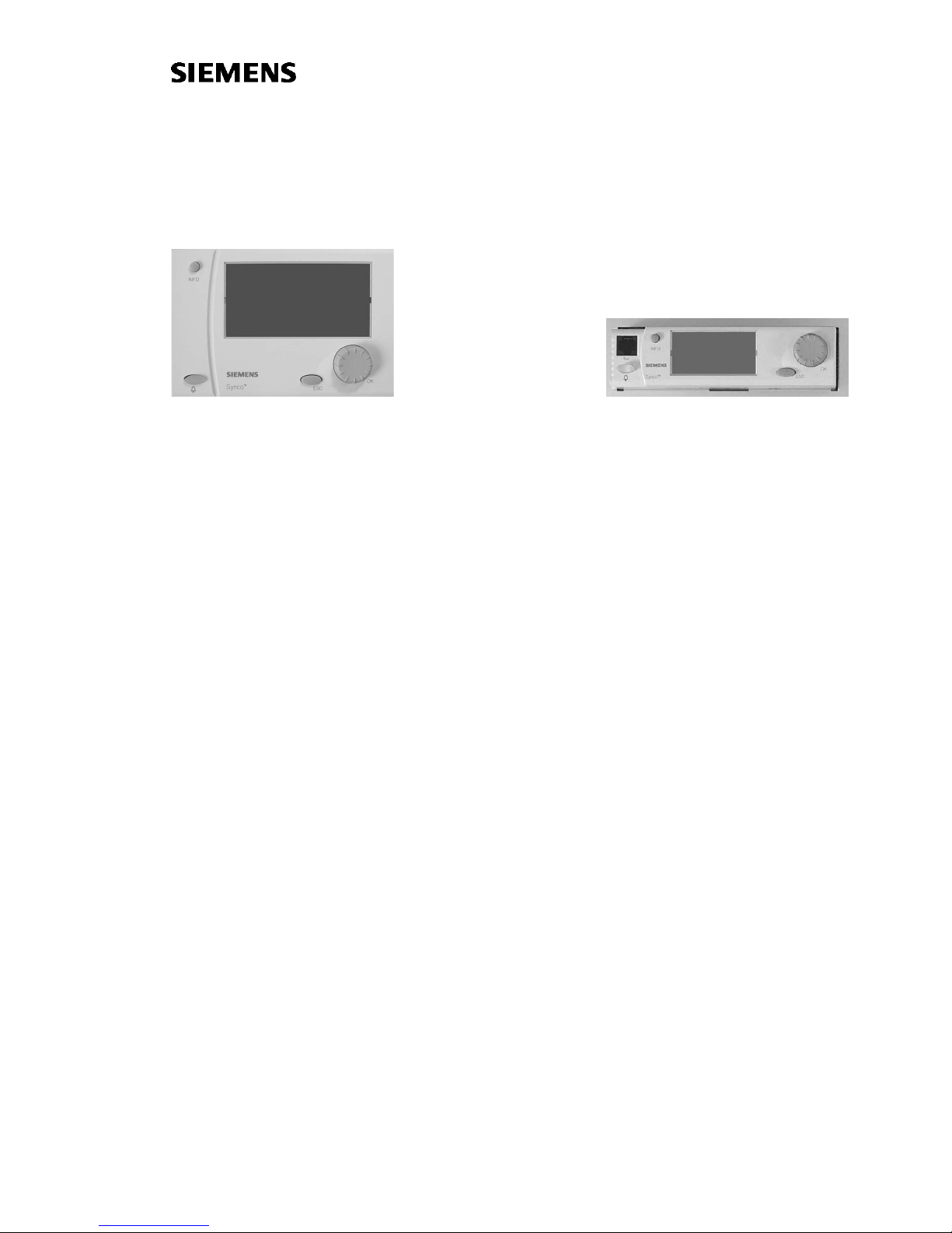
Operating elements
3111Z07
2
1
5
3
4
Plug-in type operator unit
3
4
2
5
1
3112Z08
Detached operator unit
1 Display
2 INFO button
Function 1: Displ ay of key plant data
Function 2: Display of informati on about the individual dat a
points on the current menu
3 Select-and-push knob OK
Turn: Selection of operating line and adjustment of
value
Press: Confirmation of operating line or value
4 ESC button
Going back to the previous menu
5
Fault button
with LED
LED lit / flashes: Display f ault
Press: Acknowledgement of fault or reset
Display
Operating level: The box shows th e level
on which you are (info or setting level).
Menu title: The top line indicates the menu
you are in.
Room operating mode
1-6
Preselection:
State:
Comf
Cause: Time switch
Page numbers: current / total.
Main menu
Room operating mode...
Plant operation...
Inputs...
Data acquisition...
Help picture / visualizatio n: Visualizes a
setting (e.g. switch-on / s witch-off behavior).
Cursor position: Inverse lines indic ate that
the cursor is at this position.
Scroll arr ows: The arrows indic ate that
more operating lines follow at the bott om or
top.
Dots: 3 dotes (...) indic ate that submenus
follow.
Other information prov ided in the form of pictures included, for example, the welcome picture or a pop-up window for setting
values.
Symbols and characters on the display
Symbol Meaning Symbol Meaning
Virtual operat ing mod e selector Setting level – display and sett ings
(dot indic ates the current operati ng mode). Info level – display of key plant data
Room operating mode "Comfort".
Room operating mode "Precomfort".
Room oper ating mode "Ec onomy".
Protection. Time switch
Operation selector (Logic 1) or Logic 1
Trend 1
Help pictur e ”Explanations relating to the Meter 1
query data point". Pump 1
Please wait – the controller is working Controller 1
Val ue s et Holidays
Page numbers – current / total Special day
Fault
Page 5

5 / 10
Siemens Operating Instructions R MU7..B CE1B3144_en
Building Technologies Navigate menu 2015-03-31
Navigate menu
Introduction
These Oper ating Instructions assist you in operating the controller in all standard situations (Readjust time ... etc.).
The Operating Instructions always give you the Path you need to follow through the menu to reach the relevant function – from the
start display to the adjustable value
Start display:
Wednesday
03.01.07 14:52
Welcome
« Information
Main menu »
▼
Main menu:
Main menu:
Time switch...
Room operating mode...
Controller 1...
Controller 2...
▼
Submenu:
Holidays/special days
Entry 1
––.––.–– ––.––
––.––.–– ––.––
▼
Setting the numerical value:
Entry 1
Start ––.––.–– ––.––
End ––.––.–– ––.––
Reason Holidays
Delete entry...
Start page
When not operated, the display always shows the start display – unless a fault has
occurred.
1. Press the OK knob: The list of menus appear.
Main menu:
2. Turn the OK knob: The cursor advances from one line to the next.
3. The selected line appears with a black backgr ound and invers e text.
4. Select the required option.
5. Confirm by pressing the OK knob.
Submenu
6. Now, you are on the submenus.
7. The 3 dots (...) after the text indicate that additional submenus follow.
8. Follow the in dicated path by tur ning the OK knob to find the line, then push to
confirm.
9. At the end of the path you will reach the adjustable value.
Setting the numerical value
10. The numeric al value appears as a pop-up
11. Adjust the value by tur ning the OK knob.
12. Then, confir m the value by pressing the OK knob.
13. The cursor now advances to the next value to be adjusted, or returns to the
data point if there is no other value to be adjusted.
14. Press the ESC button to return to the previous entry box or menu.
15. When you press the ESC button several times, you will reach the start display
again.
With the majority of menus, you can display inf ormation about the option current ly selected.
Press the I NFO button.
Readjust time or dateTime of day/date
All data of the yearly time switch in your controller were
entered when your plant was commissioned. If
readjustments are required, use the Time of day / date menu.
Summer and wintertime
The same is true if you n eed to readjust the dat es for the
start of summer and wintertime.
Note: Do not enter the actual dates of changeover but, in
accordanc e with international standards, the earliest
possible dates for the start of summertime and winter-time!
The menu Time of day/date
· The time of day (e.g. 09:53)
· The date (e.g. July 25)
· The year (e.g. 2007)
· The start of daylight savings time (e.g. March 25)
· The start of standard time (e.g. October 25)
Path:
Welcome > Main menu > Time of day/date... > ...
The change from wintertime to summertime, and vice versa, takes place automatically!
25.02
Page 6

6 / 10
Siemens Operating Instructions R MU7..B CE1B3144_en
Building Technologies Heat or cool per time switch program 2015-03-31
Heat or cool per time switch program
In room operating mode
, the controller operates
according to the selected heating program.
Time switch program
In the time s witch program, the start time and associated
room operating mode have been entered for all periods of
24-hour heating / cooling operation. The heating program
has been entered for you; if you wish, you c an change the
entries made (
Page 8) to satisfy your pers onal needs.
Example of a time program:
Tuesday
As of 12:30 Comf
As of 6:00 am Comfor t mode
As of 11:30 am Precomfort mode
As of 12:30 pm Comfor t mode
As of 7:00 pm Precomfort mode
As of 9:00 pm Economy mode
Do not heat or cool per time switch program
Select another room operating mode
If you do not
want to heat or cool according to the time
switch program (i.e., not automatically), you need to change
the preselection for the room operating mode.
Setpoints
The setpoints assigned to the room operating modes use
the same symbols and designations.
Setting setpoints is described on
page 7.
Symbol Room operating mode Comments
Comfor t Plant ON, H eating / Cooling on comfort
Precomfort Plant ON, H eating / Cooling on precomfort
Economy Plant OFF, Sustained mode Heating / Cooling on economy;
Night cooling and frost protection activated
Protec tion Plant OFF, fr ost protection active
Path:
Welcome > Main menu > Room operating mode... > Preselection > ...
Do not forget to switch back to auto when you only intend to heat/cool temporarily!
Operate aggregates per time switch 2
When your controller is configured with a time switch, the
controlled aggregate (e.g. a pump) is switched on and off
per the set time switch program.
If also configured with [Time switch 2] op selector, it must be
set to auto, to automatic ally switch on and off the aggregate
per the set time switch program.
If a [time switch 2] op selector is available and you do not
want
to control the aggregate per the time switch program, you
can manually override it with the [time switch 2] op selector
eit her on or off.
Example of a time program:
Time switch 2
Saturday
Switched on at 6:00 am – switched off at 10:00 pm
Path:
Welcome > Main menu > [Time switch 2] op selector > Preselection:
If you want to s et the plant to On or Off for a limit ed period only, do not forget to return to auto in due time!
Page 7

7 / 10
Siemens Operating Instructions R MU7..B CE1B3144_en
Building Technologies Room temperature 2015-03-31
Room temperature
Your universal controller offers 4 room operating modes.
Each room operating mode are assigned two temperature
setpoints (heating and cooling).
Depending on the selected room operating mode, your
controller s witches the setpoints per a time program (
page 6) or controls continuously to the setpoint for the
selected room operating mode.
The following setpoints are available. The default factory
settings represent the recommended setpoints.
You can change the comfort and pr ecomfort s etpoints as
needed. The economy setpoint cannot be set at the user
level.
Symbol
Setpoint Impact on the room? Guide value
Room operating
mode
Heating Cooling
Comfor t This is the setpoint f or the occupied room.
Ensuring comfortable conditions
21 °C 24 °C
Precomfort This is the energy saving setpoint f or the room to ensure that
comfortable conditions are reac hed quickly when changing to
comfort mode
19 °C 28 °C
Economy Plant OFF. A maximum / minimum temperature is ensured in the
room (sustained mode)
15 °C 30 °C
Prot ection Plant OFF. Fr ost protection active ---- ----
Path:
Welcome > Main menu > Controller 1... > ...
Room humidity
If your plant also includes room humidity control, the
univers al controller allows you to change the hu midity
setpoint limits in comfort and precomf ort room oper ating
modes.
Your controller changes the setpoints according to a time
switch program, or maintains the setpoint of the selected
operating mode depending on the room operating mode.
The following setpoints are available.
The default factory setti ngs represent the recommended
setpoints.
Symbol
Setpoint Impact on the room? Upper setpoint Lower setpoint
Comfor t This is the setpoint f or the occupied room.
Ensuring comfortable conditions
60 % 40 %
Precomf ort This is the energy saving setpoint for the space to ensure that
comfortable conditions will be reached quickly when changing
to comfort mode
80 % 20 %
Path:
Welcome > Main menu > Controller 2... > ...
Page 8

8 / 10
Siemens Operating Instructions R MU7..B CE1B3144_en
Building Technologies Change daily heating / cooling periods 2015-03-31
Change daily heating / cooling periods
General
In the time switch program, you can set the daily heating
and cooling periods to suit your individual needs.
Each day can accommodate a maximum of 6 switching
points; a room setpoint is assigned to each time period.
In addition to the weekdays (Mond ay through Su nday), you
can program a special d ay, that is, a special 24-hou r heating
and cooling program.
The special day is activated when you make an entry in
Holidays.
Changes on the controller are possible only if the controller's
time switch defines the program.
If an external operator st ation contr ols the program, changes
can only be made from that st ation.
Observe the following prior to making entries:
· First enter the start time for the heating/c ooling phase and
then the room operating mode f or the phase.
· The following room operating modes
, , and are
available. Set the corresponding setpoints in menu
Controller 1 and Controller 2 (
page 7).
· You can copy any 24-hour heating / cooling program to
other days.
Change and delete times and setpoints
1. Select the required day.
2. In the diagram, advance the pointer
to the time to be
changed.
3. Set the desired time.
Delete the time: Reset the time via 00:00 until ––:––
appears.
4. Select the desired operating mode.
5. If required, set additional times and select additional
setpoints.
Path:
Welcome > Main menu > Time switch... > ...
Enter additional switching points
1. Select the desired day.
2. In the diagram, advanc e pointer
to the last point in
time of the current program.
3. Turn the OK knob by one notch; ––:–– ––––––
appears.
4. Set the desired start time.
5. Set the desired room operating mode.
Copy a 24-hour heating / cooling program
1. Select the day to be c opied.
2. Turn the OK knob clockwise until Copy to: appears.
3. Press the OK knob.
4. The menu for the day selection (week sections, individual
weekdays, special day) appears.
5. Select the desired weekday or week section.
6. Copy (press the OK knob).
Create a new 24-hour program
The controller is supplied with a 24- hour program for every
day (including special days). This means that you will never
have to cr eate a new 24-hour program, but only change an
existing pr ogram.
Operating voltage off – heating / cooling program lost?
In the event of a power failure, the 24-hour programs
entered will be maintained, independent of the dur ation of
the power failure.
First, write down a 7-day schedule for daily switching times and operating modes – this will facilitate entry into the controller!
Holiday periods or special days
You can enter a total of 16 holiday periods and special days.
During a holiday period, there is no heating / cooling
program active, but only the same room operating mode. On
special day(s), the special day program is active.
Date
Enter on the submenus Entry 1, Entry 2, Entry 3, etc., the
holiday period or special day:
· Operating line start:
Date, year and time of day for the start of holidays or
special day.
· Operating line end:
Date, year and time of day f or the end of holidays or
special day.
· Operating line reason: Holidays or special day
Every entr y can be canc elled:
· Delete entry...
Room operating mode (for holidays).
Enter the desired room operating mode in the operating line
room operating mode holidays.
The following choices are available:
· Economy
or
· Pr otec tion
.
The entry will apply to all holiday periods.
Heating / cooling program (for special day)
Enter the heating / c ooling program for the special days in
Time switch.
The heating/cooling pr ogram applies to all special days.
Path:
Welcome > Main menu > Holidays/special days > Entry 1 > ...
Path:
Welcome > Main menu > Room operating mode > Room operating mode holidays > ...
Before making entries, prepare a yearly time schedule fo r all holiday periods!
Page 9

9 / 10
Siemens Operating Instructions R MU7..B CE1B3144_en
Building Technologies Display plant operating state 2015-03-31
Display plant operating state
If, during automatic heating / cooling operation, you want to
know your plant’s current operating state (the room
operating mode), go to the info level:
1. Go back to the start display by pressing the ESC butt on.
2. Press the INFO button.
The room operating mode is displayed as follows:
Room operating mode
1-5
Preselection
State Comf
Cause: Time switch
Meanings:
Preselecti on
The selected room operating mode.
In the example shown, the selector is set to
.
State
This is the current state.
In the example, heating or cooling at the comf ort setpoint.
Cause
Here, the reason for the current state is given.
Possible reasons:
· Operating mode contact (manual changeover).
· Operating mode selector.
· Occupancy button on the room unit.
· Timer button on the room unit.
· Special day
· Holidays
· Time switch for the time program (as displayed).
Display current plant data
In addition to plant data on the info pages, the submenus
configured functions allow you to query additional plant data.
Data queries are explained on
page 9 based on the
function data acquisition > Trend channel .
You find the following data via the following paths:
Trend.
Main menu > Data acquisition > Trend channel 1...2 >
Display of trend recordings of characteristics.
Meter.
Main menu > Data acquisition > Meter 1...2 >
The meters are used to acquire consumption values. The
current meter reading, the date and the reading of the last
15 months ar e displayed.
The names of the submenus used in these operating instructions may have been replaced by clear-t ext names as d efined by
your serv ice engineer.
Display measured value trends
Data acquisition… allows you to display the progr ession of up
to 2 measured values (trend channel…2). This trend function
shows measured value trends over the last 8 minutes, the
last 8 hours, the last 24 hours or the last 6 days.
Display m easured value trend:
1. Select the Data acquisition… menu.
2. S elect the required Trend channel 1…2 or the meas ured
value in clear-text; the 24-hour view of the current day
appears.
Navigate views:
1. Turn the OK knob counter clockwise to jump back the
display by 1 day, and vice versa.
2. Starting with the current 24-hour view, you reach the
view of the last 8 hours by turning t he OK knob in
clockwise direction. Turn the OK knob clockwise again
and you reach the view of the last 8 minutes, turn counter
clockwise to return.
3. Press the ESC button to go back to the previous menu.
The measured value trend is presented as follows:
Path:
Welcome > Main menu > Data acquisition… > Trend channel 1…2.
Page 10

10 / 10
Siemens Operating Instructions R MU7..B CE1B3144_en
Building Technologies Fault 2015-03-31
Fault
If a fault has occurred in the plant, it will appear on the
display and the LED inside the fault button will flash or be lit.
Proceed as f ollows:
LED flashes:
1. Press the
button to acknowledge the fault.
2. If the LED is still lit, the fault still exists or the button must
be pressed again to unlock.
LED lit:
1. Correct the f ault.
2. If the LED is still lit, the fault can be unlocked by pressing
the
button.
Unlocking is possible only after the cause of fault has
been removed.
Contact your HVAC if the fault is not corrected.
Additional information about the display of faults:
Menu Faults current.
Displays current faults. The following information is
displayed about each f ault:
· Source (e.g. pump 1).
· The fault number (for the service engineer).
· The date and the time of day the fault occurred.
Fault history...
Displays the last 10 faults. The information given is the
same as that provided for current faults.
Fault status message bus.
If your plant includes multiplied n etworked devices, faults
from other c ontrollers are displayed on your controller.
Fault indication on the setting level
Display the current fault by pressing the ESC button for 2
seconds.
Path:
Welcome > Main menu > Faults...
Required information for HVAC engineer
Your controller has characterist ic data that enable your
HVAC engineer to offer support, to answer your questions
about the plant, etc. The information is available in the
Device information... submenus.
Operating line
Explanation, example
Plant type A01.
Plant type adapted Yes.
File name AEFB01 U3B HQ.
Devic e type RMU730B-1.
Software version Of the controller.
Hardware version Of the controller.
Path:
Welcome > Main menu > Device information... > Controller... > ...
Save energy without sacrificing comfort
· During the day, do not allow the room temperature to
exceed 21 °C when heating. Each additional degree
increases heating costs by 6 to 7 %
· During the day, do not allow the room temperature to fall
below 24 °C when cooling. Each degree below that level
increases the cooling costs
· Guide values for the room temperatur e in living and
working spaces during heating and cooling periods:
– Daytime during heating period: Precomf ort = 19 °C,
Comfort = 20...22 °C.
– Daytime during the cooling period: Precomfort = 28 °C,
Comfort = 22...24 °C.
– Night time during the heating period: Economy =
14...18 °C. Pr otect objects sensitive to low
temperatures, such as plants!
– Night time during the cooling period: Economy =
29...31 °C.
· Ensure that there are no curtains, furniture or other objects
in front of or behind air inlets and outlets They have an
impact on air circulation and can caus e draf ts
· Closed shutters and blinds reduce heat loss
· Closing blinds in due time during the cooling season
reduces the impact of s olar radiation, thus saving cooling
costs
· Make sure air filters are checked and replaced at regular
intervals
If your plant uses a room unit with temperature and humidity
sensor, it s hould not be exposed to thermal and moistur e
disturbanc es since these affect the control function. For this
reason, th e following applies to the referenc e room where
the sensor is located:
· Avoid drafts through open doors
· Avoid heat gains from people, machines and lighting
· Ensure that there are no curtains, furniture or other
objects in front of temperature and humidity sens ors
Energy savings conserve our natural resources, thus contribut ing actively to environmental protection!
ã
Siemens S witzerland Ltd., 2003
Subject to change
 Loading...