

Page 1
Installation Instructions
RLA162.5U Room Temperature
procedures as specified.
CAUTION:
specified.
Document No. 129-450
October 5, 2009
Controller
Product Description
Room temperature controller for basic ventilation, air
conditioning and heating systems. Compact design
with two analog, 0 to 10 Vdc control outputs for
heating and/or cooling.
Product Numbers
RLA162.5U Automatic Heat/Cool Changeover
Warning/Caution Notations
WARNING:
Required Tools
• Small, flat-blade screwdriver
• Wire strippers
• 6-inch level
Personal injury/loss of life may
occur if you do not follow the
Equipment damage, or loss of
data may occur if you do not
follow the procedures as
Prerequisites
• Provide 24 Vac power source to thermostat wall
mounting location.
• Run wires from damper/valve actuator to
thermostat wall mounting location.
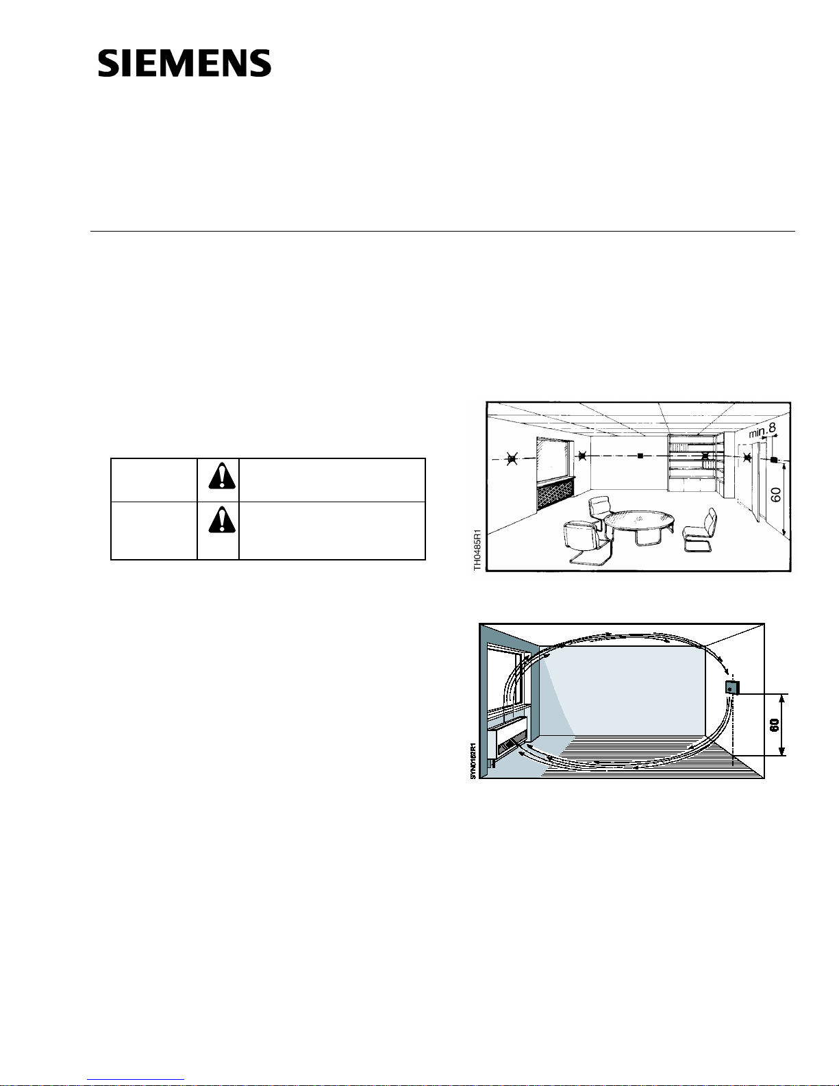
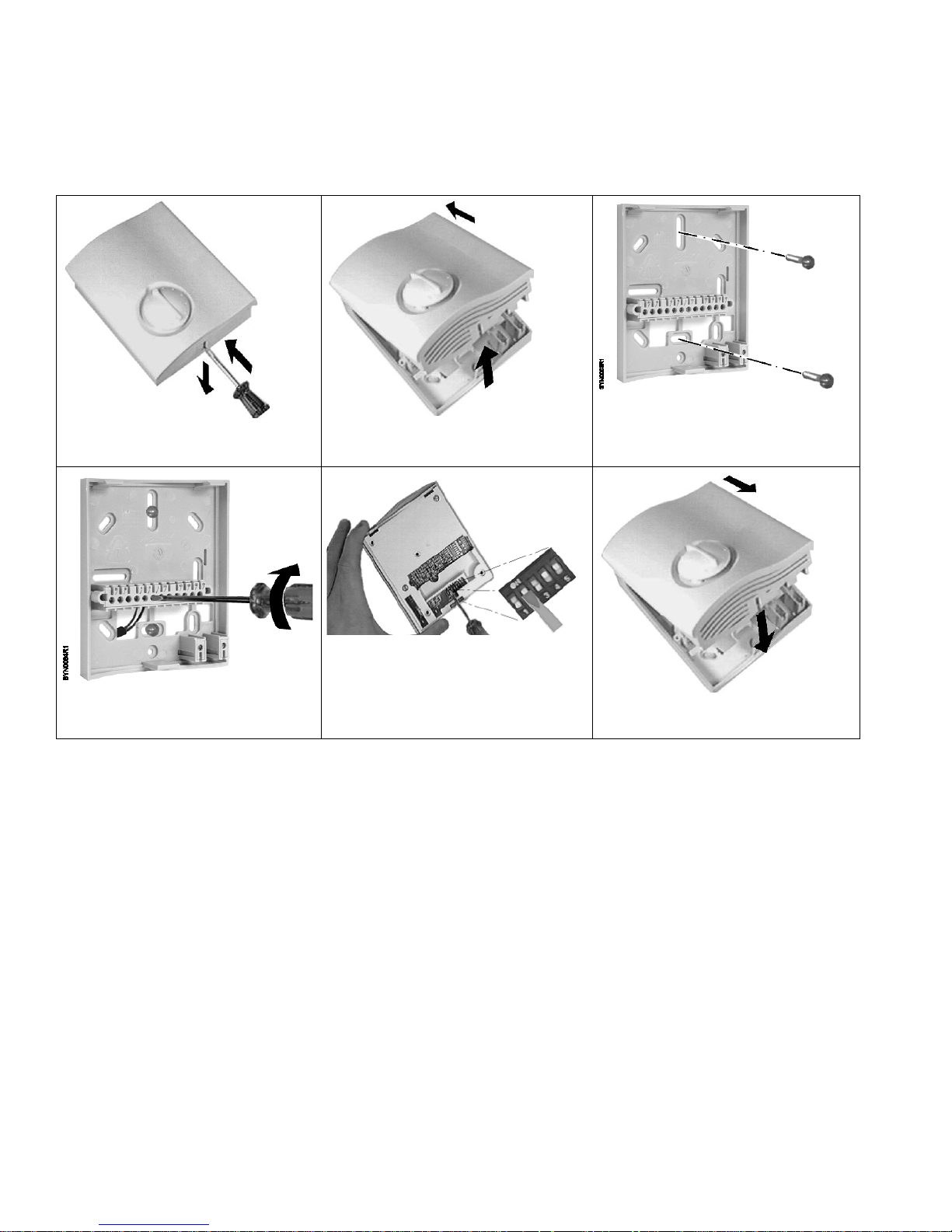
Installation
Figure 1. Acceptable Mounting Height in Inches.
Mounting Accessories
• ARG70 wall plate
• 141-570 lockable thermostat guard
• QAP22 Changeover sensor
Expected Installation Time
35 minutes
Item Number 129-450, Rev. AA Page 1 of 4
Figure 2. Airflow Requirements in Inches.
Page 2
Document No. 129-450
Installation Instructions
October 5, 2009
1 2 3
4 5 6
Page 2 of 4 Siemens Industry, Inc.
Page 3

Wiring Terminals
Function
1 2 3 4 5
Action
Operating mode
Heating and cooling in sequence
Two-stage heatin g
Single-stage cooling
Single-stage heating
P (XP1)
Heating output control
10 Vdc at setpoint conditions
0 Vdc at setpoint conditions
1 Operating voltage, 24 Vac positiv e
2 Operating voltage, 24 Vac negati ve
D1 Day/night changeover
5 Limitation input 0 to 10 Vdc
GND Ground for day/night changeover
10 Measuring Neutral
11 Heat/cool changeover sensor
13 Fan or auxiliary relay, positive
18 Control signal, 0 to 10 Vdc, Heat 1
19 Control signal, 0 to 10 Vdc, Cool or
Heat 2
20 Fan or auxiliary relay, negative
Figure 3. RLA162.5U Wiring Terminals.
Wiring Diagrams
Document No. 129-450
Installation Instructions
October 5, 2009
Figure 5. RLA162.5U Room Temperature Control with
Minimum Limitation of the Supply Air Temperature.
B2 Heat/cool changeover sensor
E1 Fan or auxiliary unit
F2 Freeze stat
M Neutral
N1 Room temperature controller (RLA162.5U)
N2 Air duct temperature controller (RLM162U) as a
limiter
R Resistive input
S1 Time clock or switch for day/night setpoint
changeover
U 0 to 10 Vdc output feedback
Y 0 to 10 Vdc input signal
Y1 Heating valve actuator
Y2 Cooling valve actuator
Z9 Limit thermostat
Figure 4. RLA162.5U Room Temperature Control with
Setpoint Changeover.
Commissioning
Control mode
Action (18)
Cooling/Second stage
output Control Action (19)
The factory default setting for all five switches is OFF.
Siemens Industry, Inc. Page 3 of 4
Table 1. DIP Switch Settings.
PI (integral action time 600 seconds)
0 Vdc at setpoint conditions
10 Vdc at setpoint conditions
Page 4

Document No. 129-450
Siemens Indus try, Inc.
+ 1 847-215-1000
Your feedback is important to us. If you have
Document No. 129-450
Response
Possible Causes
Valve does not
Valve travels in the
Control responds
too slowly
Control is unstable
Installation Instructions
October 5, 2009
Commissioning, Continued
Proportional band adjustment (XP1): Potentiometer setting should correspond to the required
0°F to 90°F (0 K to 50 K) range of the controller’s output signal.
Energy saving adjustment (ECO): Potentiometer setting should correspond to the required
0°F to 18°F (0 K to 10 K) offset of normal setpoint. Energy Saving = Normal setpoint
+/- offset.
NOTE: XP1 and ECO adjustments must be made by the user; factory settings are zero or “random”.
Troubleshooting
• Valve not connected
respond
wrong direction
• No power supply
• Selection of operating action is
wrong. DIP Switches 4 (Y1) and
5 (Y2) should match control
action of the valve actuator.
• Wrong controller terminal used
• Reduce P-band (XP1)
Dimensions
• Increase P-band (XP1)
Figure 6. Dimensions in Inches (Millimeters).
Information in this publication is based on current specifications. The company reserves the right to make changes in specifications and models as
design improvements are introduced. Teflon is a registered trademark of DuPont. Product or company names mentioned herein may be the trademarks
of their respective owners. © 2009 Siemens Building Technologies, Inc.
Building Technologies Division
1000 Deerfield Parkway
Buffalo Grove, IL 60089
comments about this document, please send them
to SBT_technical.editor.us.sbt@siemens.com
Printed in the USA
Page 4 of 4
 Loading...