

Page 1

RL 147 Positioning Relay Calibration
Product Description
This sheet provides the instructions to calibrate the
RL 147 Positioning Relay after it has been mounted
on an actuator.
Product Number
NOTE:
Installation Instructions
Document No. 129-125
Rev. 5, June, 2000
In some cases, the actuator stem travel or
stroke is not identical to the nominal value
of the relay feedback spring. See
Calculating The Span Setting
the span setting on the feedback arm.
to determine
147-2000
Required Tools
•
Medium flat-blade screwdriver
•
Tubing, pressure gauge, and squeeze bulb
(Part of Calibration kit 832-177)
•
Two 5/8-inch open end wrenches
•
Two 7/16-inch open end wrenches for valve
stems of 1/4-inch diameter
Expected Installation Time
10 Minutes
Prerequisites
•
For field installed relays, mount the
positioning relay on the actuator according
to the instructions that are packaged with
the mounting kit.
•
Check that you have the correct feedback
spring(s) attached.
−
If the positioning relay is mounted on a
valve, see
−
If the stroke of the No. 6 damper
actuator has been adjusted, see
Table 1
Identify the desired operating span and the start
point pressure.
Tables 4 and 6.
.
Installation
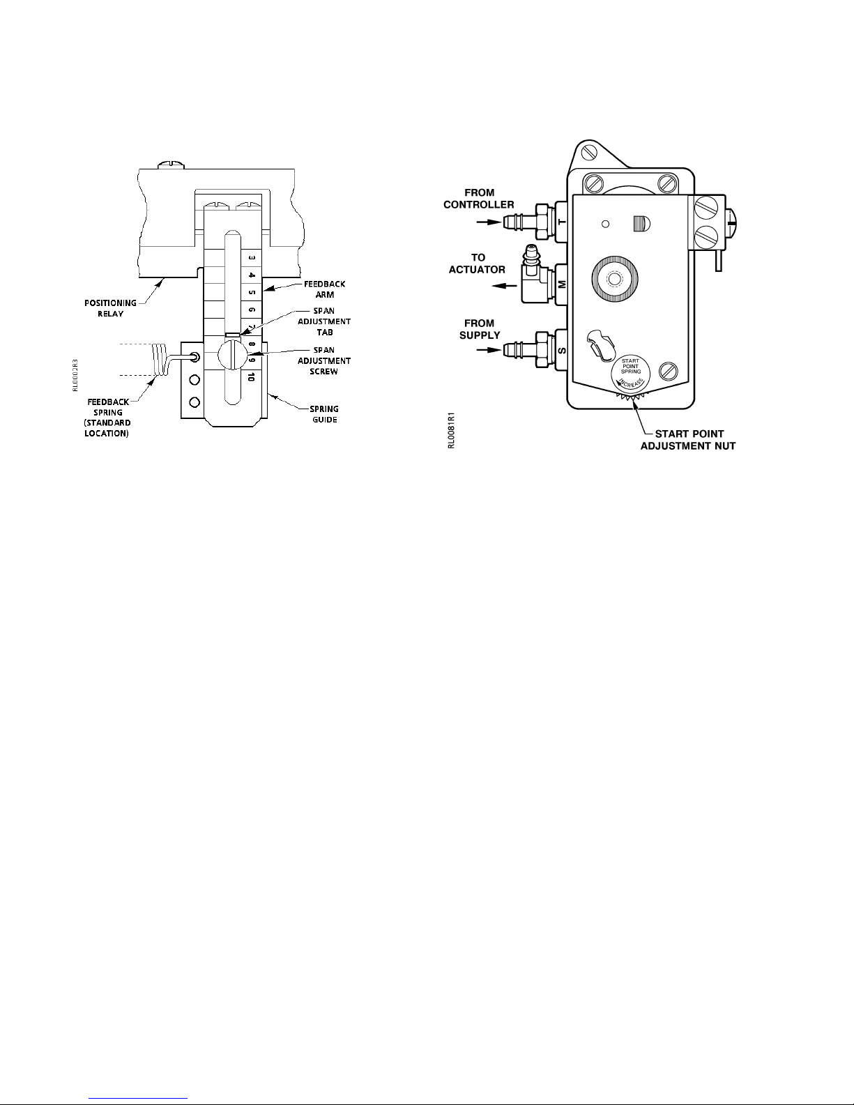
Setting the span
The positioning relay operating span can be set for
spans of 3 to 12 psig (21 to 83 kPa).
For spans of 3 through 10 psig (21 to 69 kPa)
1. Check that the feedback spring is attached to
the spring guide in the hole across from the
span adjustment screw. This is identified as the
standard location in
2. With a screwdriver, loosen the span adjustment
screw. Move the spring guide on the feedback
arm until the span adjustment tab is at the
desired span setting reference number.
NOTE:
3. Tighten the span adjustment screw.
4. The feedback spring must be parallel to the
actuator shaft or valve stem. Use the open end
wrenches to loosen the hex nuts holding the
spring arm in position on the shaft or stem.
Align the feedback spring and tighten the hex
nuts.
5. The feedback spring should have no slack or no
stretch in it. Adjust the wing nuts and
adjustment nut, if necessary.
The line to the left of the number is the
setting.
(See
Figure 1.
Figure 1
)
Page 1 of 5
Page 2
Document No. 129-125
Installation Instructions
Rev. 5, June, 2000
Installation, Continued
Figure 1. Span Adjustment.
Shown at Span Setting 8.
For spans of 11 or 12 psig (76 or 83 kPa)
Figure 2. Start Point Adjustment
1. Move the span adjustment tab to the 10 setting
on the feedback arm. Follow steps 2 and 3 for
Setting the span
2. Move the feedback spring one hole away from
the standard location for a span of 11 psig
(76 kPa) and two holes away from the standard
spring location for a 12 psig (83 kPa) span. See
Figure 1
3. Follow steps 4 and 5 for
.
Adjusting the start point
The positioning relay can be adjusted to start
actuator movement at pressures between 3 and 10
psig (21 and 69 kPa).
1. Remove the relay cover.
2. Attach tubing with a pressure gauge and
squeeze bulb to the "T" port. Supply air should
be attached to the "S" port. The "M" port should
be attached to the connector on the actuator.
3. Using the squeeze bulb, apply pressure to the
relay. Watch the valve stem or actuator shaft to
see when it begins to move. Check the
pressure gauge; this is the start point pressure.
4. If this is not the desired start point pressure,
turn the start point adjustment nut (
clockwise to increase the start point pressure
and counterclockwise to decrease the pressure.
.
Setting the span
Figure 2
(see
.
Figure 2
)
)
Adjusting the span
1. Using the squeeze bulb, apply pressure to the
relay. Note the pressure at which the stem or
shaft begin to move.
2. Continue to apply pressure until the stem or
shaft completes its full stroke. Note the
pressure.
3. The difference between the two pressures is
the
span.
4. If the span is not the desired span, move the
spring guide to a higher reference number to
increase the span or lower number to decrease
the
span. See
5. Repeat steps 1 through 4 until you get the
desired
6.
If you have moved the spring guide, adjust the
spring arm so that the spring is parallel to the
stem or shaft.
7.
Check the feedback spring. There should be no
slack nor stretch in it. Adjust the wing nuts and
adjustment nut, if necessary.
8. Fasten the relay cover. Fill in the information on
the calibration label.
9. Attach the air line from the controller to the "T"
port.
Figure 1
span.
Setting the Span
and
.
5. Repeat steps 3 and 4 until the stem or shaft
begins to move at the desired pressure.
Page 2 of 5
Siemens Building Technologies, Inc.
Page 3

Document No. 129-125
Installation Instructions
Rev. 5, June, 2000
Installation, Continued
Table 1. Spring Selection for Adjustable Stroke
of the No. 6 Damper Actuator.
Actuator
Stroke
3-1/4 to 4
(82 to 102)
2-29/32 to
3-1/4
(74 to 82)
Dimensions in inches (millimeters).
Feedback Spring
Color Nominal Max
Blue 4
(102)
Cadmium 3
(76)
4-1/4
(108)
3-1/4
(82)
Adjusting
Screw
4-1/2 (114)
long
1-3/4 (44)
long
Calculating the span setting
1. Identify the stem/stroke travel from
3, 5, or 6.
2. If the stem travel matches a nominal spring
travel listed in
Table 4
there is no need to
calculate a new span setting.
3. If the stem travel does not match a nominal
spring travel listed in
Table 4
spring(s) whose maximum allowable travel is
equal to or greater than the actual stem travel.
4. Calculate the span setting with the following
formula:
Tables 1, 2,
, chose the
Formula for Span Setting
Span
setting
=
Desired
span
Nominal sp ring travel
Actuator stroke
Example:
Determine the span setting for a valve
having a desired span of 5 psig and
5/16-inch stroke.
Select a spring with a maximum allowable range
equal to or larger that the stroke. Use the 1/4-inch
spring with a 3/8-inch maximum allowable travel
range. See
Span
setting
Table 4
=5 x
.
0.25
=4
0.312
Set the span adjustment tab to line 4 on the
feedback arm to provide a 5 psig span for this valve.
Table 2. Stem Travel for VF 599 Valve Bodies.
Stem Travel in Inches (mm)Line size
in Inches
(mm)
1/2 through 2
(15 though 50)
2-1/2 (65) 3/4 (20) 3/4 (20)
3 (80) 3/4 (20) 3/4 (20)
4 (100) – 1-1/2 (40)
5 (125) – 1-1/2 (40)
6 (150) – 1-1/2 (40)
8-inch
Actuator
3/4 (20) –
12-inch
Actuator
Table 3. Stem Travel Listed by Valve Type.
Line Size
Inches
(mm)
1/2 (13) 3/8 (9.5) – 1/8 (3.2) – – –
3/4 (19) 3/4 (19) – 3/16 (4.8) – – –
1 (25) 3/4 (19) 3/16 (4.8) 1/4 (6.4) – – –
1-1/4 (32) 1 (25) 1/4 (6.4) 5/16 (7.9) – – –
1-1/2 (38) 1 (25) 1/4 (6.4) 5/16 (7.9) – – –
2 (51) 1 (25) 3/8 (9.5) N.O.
2-1/2 (64) 5/8 (16) 3/8 (9.5) N.O.
3 (76) 3/4 (19) 9/16 (14) 3/4 (19) 1-1/8 (29) 3/4 (19) 1 (25)
4 (102) 1 (25) 9/16 (14) 1 (25) 1-1/4 (32) 1-1/8 1-3/8 (35)
5 (127) – – – 1-1/2 (38) 1-1/4 (32) 1-3/8 (35)
6 (152) – – – 1-1/2 (38) 1-1/4 (32) 1-3/8 (35)
8 (203) – – – – 1-1/2 (38) –
VP 591
Single Seat
Double Seat
5/16 (7.9) N.C.
5/16 (7.9) N.C.
Siemens Building Technologies, Inc.
Flowrite™ Valve Stem Travel in Inches (mm)
VP 591
VP 591
WM
5/16 (7.9) – – –
5/8 (16) 1-1/8 (29) 3/4 (19) 1 (25)
VP 593
Single Seat
VP 593
Double Seat
VP 593
WM
Page 3 of 5
Page 4

Document No. 129-125
Installation Instructions
Rev. 5, June, 2000
Table 4. Spring Selection.
Spring Travel Range Recommended Springs
Nominal
Inches (mm)
5/32 (5.0) 1/4 (6.4) 147-298 Small Green
1/4 (6.4) 3/8 (9.5) 147-289 Small Cadmium Plate
3/8 (9.5) 1/2 (13) (2)147-298 Small Green
1/2 (13) 3/4 (19) (2)147-289 Small Cadmium Plate
3/4 (19) 1 (25) 147-290 1-3/8" Red
1 (25) 1-1/4 (32) 147-291 Long Green
1-1/4 (32) 1-5/8 (41) 147-289
1-1/2 (38) 2 (51) (2)147-290 Small Red
1-3/4 (44) 2-1/4 (57) 147-290
2 (51) 2-1/2 (64) (2)147-291 Long Green
2-3/8 (60) N/A 147-105 2" Red
3 (76) 3-1/4 (83) 147-292 Long Cadmium Plate
3-3/4 (95) 4 (102) 147-301 3" Red
4 (102) 4-1/4 (108) 147-293 Blue
4 (102) 6 (152) 147-313 Zinc PI. or Yell. Chr.
7 (178) 12-1/4 (311) 147-330 Zinc Plate
Max. Allowable
Inches (mm)
Part No. Size & Color
Small Cadmium Plate
plus
147-291
plus
147-291
plus
Long Green
Small Red
plus
Long Green
Flowrite
Product
Number
599-05920 3/4 (20)
599-05921 3/4 (20)
599-05922 1-1/2 (40)
599-05923 1-1/2 (40)
599-05924 1-1/2 (40)
599-05930 3/4 (20)
599-05931 3/4 (20)
599-05932 1-1/2 (40)
599-05933 1-1/2 (40)
599-05934 1-1/2 (40)
599-05940 3/4 (20)
599-05941 3/4 (20)
599-05942 1-1/2 (40)
599-05943 1-1/2 (40)
599-05944 1-1/2 (40)
599-05950 3/4 (20)
599-05951 3/4 (20)
599-05952 1-1/2 (40)
599-05953 1-1/2 (40)
599-05954 1-1/2 (40)
599-05960 3/4 (20)
599-05961 3/4 (20)
599-05962 1-1/2 (40)
599-05963 1-1/2 (40)
599-05964 1-1/2 (40)
Stem Travel
Inches
(mm)
Table 5 Flowrite 599 Valve Body Listed by Product Number.
Flowrite
Product
Number
599-05970 3/4 (20)
599-05971 3/4 (20)
599-05972 1-1/2 (40)
599-05973 1-1/2 (40)
599-05974 1-1/2 (40)
599-05980 3/4 (20)
599-05981 3/4 (20)
599-05982 1-1/2 (40)
599-05983 1-1/2 (40)
599-05984 1-1/2 (40)
599-05990 3/4 (20)
599-05991 3/4 (20)
599-05992 1-1/2 (40)
599-05993 1-1/2 (40)
599-05994 1-1/2 (40)
599-06040 3/4 (20)
599-06041 3/4 (20)
599-06042 1-1/2 (40)
599-06043 1-1/2 (40)
599-06044 1-1/2 (40)
599-06050 3/4 (20)
599-06051 3/4 (20)
599-06052 1-1/2 (40)
599-06053 1-1/2 (40)
599-06054 1-1/2 (40)
Stem Travel
Inches
(mm)
Flowrite
Product
Number
599-06060 3/4 (20)
599-06061 3/4 (20)
599-06062 1-1/2 (40)
599-06063 1-1/2 (40)
599-06064 1-1/2 (40)
599-06070 3/4 (20)
599-06071 3/4 (20)
599-06072 1-1/2 (40)
599-06073 1-1/2 (40)
599-06074 1-1/2 (40)
599-06120 3/4 (20)
599-06121 3/4 (20)
599-06122 1-1/2 (40)
599-06123 1-1/2 (40)
599-06124 1-1/2 (40)
599-06130 3/4 (20)
599-06131 3/4 (20)
599-06132 1-1/2 (40)
599-06133 1-1/2 (40)
599-06134 1-1/2 (40)
599-06140 3/4 (20)
599-06141 3/4 (20)
599-06142 1-1/2 (40)
599-06143 1-1/2 (40)
599-06144 1-1/2 (40)
Stem Travel
Inches
(mm)
Flowrite
Product
Number
599-06150 3/4 (20)
599-06151 3/4 (20)
599-06152 1-1/2 (40)
599-06153 1-1/2 (40)
599-06154 1-1/2 (40)
599-06160 3/4 (20)
599-06161 3/4 (20)
599-06162 1-1/2 (40)
599-06163 1-1/2 (40)
599-06164 1-1/2 (40)
599-06165 3/4 (20)
599-06166 3/4 (20)
599-06167 1-1/2 (40)
599-06168 1-1/2 (40)
599-06169 1-1/2 (40)
599-06170 3/4 (20)
599-06171 3/4 (20)
599-06172 1-1/2 (40)
599-06173 1-1/2 (40)
599-06174 1-1/2 (40)
599-06175 3/4 (20)
599-06176 3/4 (20)
599-06177 1-1/2 (40)
599-06178 1-1/2 (40)
599-06179 1-1/2 (40)
Stem Travel
Inches
(mm)
Page 4 of 5
Siemens Building Technologies, Inc.
Page 5

Flowrite
Product
Number
Stem Travel
Inches
(mm)
591-6480 5/8 (16)
591-6490 3/4 (19)
591-6540 5/8 (16)
591-6600 1/8 (3.2)
591-6610 3/16 (4.8)
591-6620 1/4 (6.4)
591-6630 5/16 (7.9)
591-6640 5/16 (7.9)
591-6650 5/16 (7.9)
591-6720 5/8 (16)
591-6730 3/4 (19)
591-6740 1 (25)
591-6840 3/8 (9.5)
591-6850 9/16 (14)
591-6860 9/16 (14)
591-6870 5/16 (7.9)
591-6880 9/16 (14)
591-6890 9/16 (14)
591-6900 1/4 (6.4)
591-6910 1/4 (6.4)
591-6920 5/16 (7.9)
591-6930 9/16 (14)
591-6940 3/16 (4.8)
591-6950 1/4 (6.4)
591-6960 1/4 (6.4)
591-6970 3/8 (9.5)
591-6980 3/16 (4.8)
591-7000 1/4 (6.4)
591-7010 5/16 (7.9)
591-7020 3/16 (4.8)
591-7030 1/4 (6.4)
591-7040 1/4 (6.4)
591-7050 3/8 (9.5)
591-7060 3/8 (9.5)
591-7070 9/16 (14)
591-7080 9/16 (14)
591-7090 3/16 (4.8)
591-7100 5/16 (7.9)
591-7110 9/16 (14)
591-7870 3/4 (19)
References
Technical Inst ructions
RL147-2
155-038P25
Table 6. Stem Travel Listed by Product Number.
Flowrite
Product
Number
Stem Travel
Inches
(mm)
591-7871 3/4 (19)
591-7872 1 (25)
591-7873 1 (25)
591-7874 1 (25)
591-7875 3/4 (19)
591-7876 3/4 (19)
591-7877 1 (25)
591-7878 1 (25)
591-7879 1 (25)
591-7971 3/8 (9.5)
591-7972 3/4 (19)
591-7973 3/4 (19)
591-7974 1 (25)
591-7975 1 (25)
591-7976 1 (25)
591-7977 3/8 (9.5)
591-7978 3/4 (19)
591-7979 3/4 (19)
591-7980 1 (25)
591-7981 1 (25)
591-7982 1 (25)
591-8016 5/8 (16)
591-8017 5/8 (16)
591-8018 3/4 (19)
591-8019 3/4 (19)
591-8020 1 (25)
591-8021 1 (25)
591-8028 5/8 (16)
591-8029 3/4 (19)
591-8030 1 (25)
591-8071 3/8 (9.5)
591-8072 3/4 (19)
591-8073 3/4 (19)
591-8074 1 (25)
591-8075 1 (25)
591-8076 1 (25)
591-8077 3/8 (9.5)
591-8078 3/4 (19)
591-8079 3/4 (19)
591-8080 1 (25)
Flowrite
Product
Number
Stem Travel
Inches
(mm)
591-8081 1 (25)
591-8082 1 (25)
591-8330 5/8 (16)
591-8331 5/8 (16)
591-8332 3/4 (19)
591-8336 5/8 (16)
591-8337 5/8 (16)
591-8338 3/4 (19)
591-8339 3/4 (19)
591-8340 1 (25)
591-8341 1 (25)
593-8342 1-1/2 (38)
593-8344 1-1/2 (38)
593-8350 1-1/8 (29)
593-8351 1-1/8 (29)
593-8352 1-1/8 (29)
593-8353 1-1/8 (29)
593-8354 1-1/8 (29)
593-8355 1-1/8 (29)
593-8356 1-1/8 (29)
593-8357 1-1/8 (29)
593-8358 1-1/4 (32)
593-8359 1-1/4 (32)
593-8360 1-1/2 (38)
593-8362 1-1/2 (38)
593-8364 1-1/8 (29)
593-8365 1-1/8 (29)
593-8366 1-1/8 (29)
593-8367 1-1/8 (29)
593-8368 1-1/8 (29)
593-8369 1-1/8 (29)
593-8370 1-1/8 (29)
593-8371 1-1/8 (29)
593-8372 1-1/4 (32)
593-8373 1-1/4 (32)
593-8374 1-1/2 (38)
593-8376 1-1/2 (38)
593-8378 1-1/4 (32)
593-8379 1-1/4 (32)
593-8380 1-1/4 (32)
Document No. 129-125
Installation Instructions
Rev. 5, June, 2000
Flowrite
Product
Number
593-8381 1-1/4 (32)
593-8382 1-1/2 (38)
593-8383 1-1/2 (38)
593-8388 3/4 (19)
593-8389 3/4 (19)
593-8390 3/4 (19)
593-8391 3/4 (19)
593-8392 1-1/8 (29)
593-8393 1-1/8 (29)
593-8394 1-1/4 (32)
593-8395 1-1/4 (32)
593-8396 1-1/4 (32)
593-8397 1-1/4 (32)
593-8398 1-1/4 (32)
593-8399 1-1/4 (32)
593-8400 1-1/4 (32)
593-8401 1-1/4 (32)
593-8402 1-1/2 (38)
593-8403 1-1/2 (38)
593-8404 1-1/4 (32)
593-8405 1-1/4 (32)
593-8406 1-1/4 (32)
593-8407 1-1/4 (32)
593-8410 1-1/2 (38)
593-8411 1-1/2 (38)
593-8412 1-3/8 (35)
593-8413 1-3/8 (35)
593-8415 1 (25)
593-8416 1 (25)
593-8419 1 (25)
593-8420 1 (25)
593-8421 1-3/8 (35)
593-8422 1-3/8 (35)
593-8423 1-3/8 (35)
594-8343* 1-1/2 (38)
594-8345* 1-1/2 (38)
594-8361* 1-1/2 (38)
594-8363* 1-1/2 (38)
594-8375* 1-1/2 (38)
594-8377* 1-1/2 (38)
* RL 147 is standard with
this product.
Stem Travel
Inches
(mm)
Information in this publication is based on current specifications. The company reserves the right to make changes in specifications and
models as design improvements are introduced. Flowrite is a t rademark of Siemens Building Technologies, Inc. © 2000 Siemens Building
Technologies, Inc.
Siemens Building Technologies, Inc.
Landis & Staefa Division
1000 Deerfield Parkway
Buffalo Grove, IL 60089-4513
U.S.A.
Your feedback is important to us. If you have
comments about this document, please send
them to technical.editor@ sb t .siemens.com
Document No. 129-125
Printed in the U.S.A.
Page 5 of 5
 Loading...