

Page 1
November 1999
RGZESDI
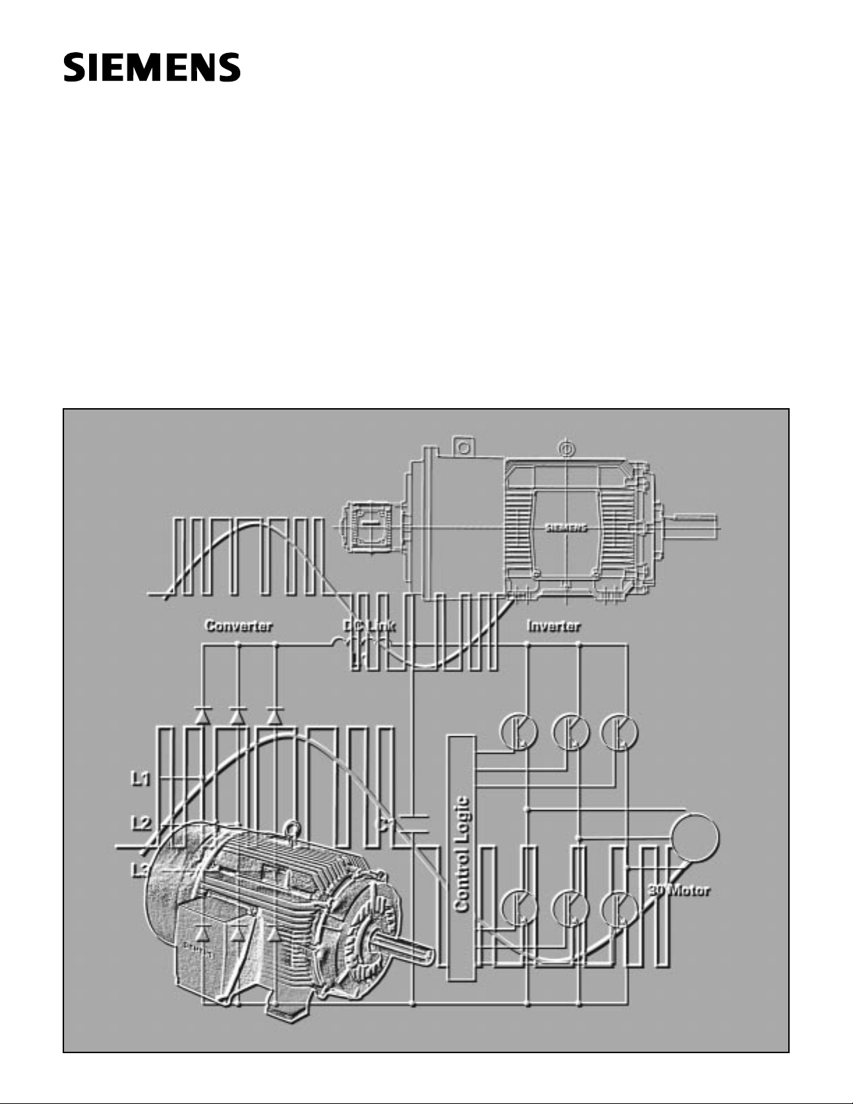
Inverter Duty AC Induction Motors
Installation • Operation • Maintenance Instructions
Frames: 143T through S449SS/LS
Page 2

QUALIFIED PERSON
For the purposes of this manual and product labels a qualified person is one who is familiar with the installation,
construction, operation or maintenance of the equipment and the hazards involved. In addition this person has
the following qualifications:
(a) Is trained and authorized to energize, de-energize, clear, ground and tag circuits and equipment in accor-
dance with established safety practices.
(b) Is trained in the proper care and use of protective equipment such as rubber gloves, hard hat, safety glasses
or face shields, flash clothing, etc., in accordance with established safety practices.
(c) is trained in rendering first aid.
SIGNAL WORDS
The signal words “Danger,” Warning” and “Caution” used in this manual indicate the degrees of hazard that
may be encountered by the user. These words are defined as:
Danger - Indicates death or serious injury will result if proper precautions are not taken.
Warning - Indicates death or serious injury or property damage can result if proper precautions are not taken.
Caution - Indicates some injury or property damage may result if proper precautions are not taken.
Page 3
INTRODUCTION . . . . . . . . . . . . . . . . . . . . . . . . . . . . . . . . . . . . . . . . . . . . . . . . . . . . . . . . . . . . . . . . . . . . . . . . . 4
INSPECTION . . . . . . . . . . . . . . . . . . . . . . . . . . . . . . . . . . . . . . . . . . . . . . . . . . . . . . . . . . . . . . . . . . . . . . . . . . . . 4
STORAGE . . . . . . . . . . . . . . . . . . . . . . . . . . . . . . . . . . . . . . . . . . . . . . . . . . . . . . . . . . . . . . . . . . . . . . . . . . . . . . 5
INSTALLATION . . . . . . . . . . . . . . . . . . . . . . . . . . . . . . . . . . . . . . . . . . . . . . . . . . . . . . . . . . . . . . . . . . . . . . . . . . 5
OPERATION . . . . . . . . . . . . . . . . . . . . . . . . . . . . . . . . . . . . . . . . . . . . . . . . . . . . . . . . . . . . . . . . . . . . . . . . . . . . . 5
VFD OPERATION . . . . . . . . . . . . . . . . . . . . . . . . . . . . . . . . . . . . . . . . . . . . . . . . . . . . . . . . . . . . . . . . . . . . . . . . . 6
ACCESSORIES
• THERMOSTATS . . . . . . . . . . . . . . . . . . . . . . . . . . . . . . . . . . . . . . . . . . . . . . . . . . . . . . . . . . . . . . . . . . . . 6
• BLOWERS . . . . . . . . . . . . . . . . . . . . . . . . . . . . . . . . . . . . . . . . . . . . . . . . . . . . . . . . . . . . . . . . . . . . . 6 - 7
• ENCODERS . . . . . . . . . . . . . . . . . . . . . . . . . . . . . . . . . . . . . . . . . . . . . . . . . . . . . . . . . . . . . . . . . . . . . . . 7
MAINTENANCE
• BEARING LUBRICATION . . . . . . . . . . . . . . . . . . . . . . . . . . . . . . . . . . . . . . . . . . . . . . . . . . . . . . . . . . . . . 7
• INSULATION RESISTANCE . . . . . . . . . . . . . . . . . . . . . . . . . . . . . . . . . . . . . . . . . . . . . . . . . . . . . . . . . . . 8
• CLEANING . . . . . . . . . . . . . . . . . . . . . . . . . . . . . . . . . . . . . . . . . . . . . . . . . . . . . . . . . . . . . . . . . . . . . . . . 8
SERVICE . . . . . . . . . . . . . . . . . . . . . . . . . . . . . . . . . . . . . . . . . . . . . . . . . . . . . . . . . . . . . . . . . . . . . . . . . . . . . . . 8
November 1999
TABLE OF CONTENTS
3
IMPORTANT
These instructions do not purport to cover all details or variations in equipment, nor to provide for every possible
contingency to be met in connection with installation, operation or maintenance. Should further information be
desired or should particular problems arise which are not covered sufficiently for the purchaser’s purposes, the
matter should be referred to the local Siemens sales office. The contents of this instruction manual shall not
become part of or modify any prior or existing agreement, commitment or relationship. The sales contract contains the entire obligation of Siemens. The warranty contained in the contract between the parties is the sole
warranty of Siemens. Any statements contained herein do not create new warranties or modify the existing
warranty.
Page 4

STORAGE
Motors must be stored in a clean,
dry, well ventilated location free
from vibration and rapid or wide
temperature variations. If the unit is
to be stored longer than three
months, consult the factory. Ball
bearing motors are shipped from
the factory properly lubricated and
ready to operate. When in storage,
the motor shaft must be turned
several rotations every month and
the bearing re-lubricated every year.
On non-explosion-proof TEFC
motors, a removable plug in the
bottom of the frame or housing permits removal of accumulated mois-
ture. Drain regularly if storage
atmosphere results in formation of
condensation.
INSTALLATION
Qualified service or maintenance
personnel must handle installation,
The motor foundation must rigidly
support all four feet in the same
plane. Place shims under the motor
feet, as required; so they will not
be pulled out of plane when mounting bolts are tightened. All wiring to
the motor and control must be in
accordance with the National
Electrical Code and all local regulations. Before load is connected,
momentarily energize motor to
check that the direction of rotation
is proper. For direct connected
loads, accurate alignment is 0.004
inch/ft. (Radius to dial Indicator =
one foot)
Any change in shims requires rechecking alignment. When alignment is within limits, dowel two
feet of each unit. When installing
V-belt sheave, spur or helical pinion
or chain drives, be certain that they
are within NEMA limitations. Refer
to NEMA motor and general standards, MG1-14.07 and 14.41.
INTRODUCTION
THIS EQUIPMENT CONTAINS
HAZARDOUS VOLTAGES,
ROTATING PARTS AND HOT
SURFACES. SEVERE PERSONAL
INJURY OR PROPERTY DAMAGE CAN RESULT IF SAFETY
INSTRUCTIONS ARE NOT FOLLOWED. ONLY QUALIFIED PERSONNEL SHOULD WORK ON
OR AROUND THIS EQUIPMENT
AFTER BECOMING THOROUGHLY FAMILIAR WITH ALL
WARNINGS, SAFETY NOTICES,
AND MAINTENANCE PROCEDURES CONTAINED HEREIN.
THE SUCCESSFUL AND SAFE
OPERATION OF THIS EQUIPMENT IS DEPENDENT UPON
PROPER HANDLING, INSTALLATION, OPERATION AND MAINTENANCE.
INSPECTION
Care is taken at the factory to
assure that the motor arrives at its
destination in first class condition. If
there is evidence of rough handling
or damage in shipping, file a claim
at once with the carrier and notify
your Siemens Sales Office.
Examine the outside of the motor
carefully for damage, with particular
attention to conduit box, fans, and
covers. Inspect and tighten all hardware and accessories, which may
have become loosened during shipping and handling. Turn the shaft by
hand to be sure that it rotates
freely. If the motor has been mishandled sufficiently to break external parts, the end shield should also
be removed to check for internal
damage unless the motor is explosion proof. See warning below on
explosion proof motors.
November 1999
INSTALLATION & OPERATION
WARNING
4
Explosion.
Can cause death, serious injury or property damage.
When repairing and reassembling a motor that has an underwriter’s label, it is imperative that the unit be re-inspected and:
1 All original fits and tolerances are maintained.
2 All plugs and hardware be securely fastened.
3 Any parts replacements, including hardware, be accurate
duplicates of the Originals.
Repair work on explosion proof-motors can only be performed
by the original manufacturer or U.L. certified shops. Violations
of any of the above items will invalidate the significance of the
U.L. Label.
Page 5

5
VFD OPERATION
Special consideration must be paid
to ensure that the motor is operated within recommended guidelines
for torque and speed for the type
and size of RGZESDI motors selected. Under no circumstances should
the motor be operated at frequencies beyond the safe mechanical
limits shown below in this document.
RGZESDI Constant Torque motors
provide full rated torque within their
listed speed range, without exceeding their Class F temperature rating
on PWM (pulse width modulated)
inverter power. Speed ranges are
based on use with vector type IGBT
inverters, set at a minimum 3 kHz
switching frequency, and are
designed for operation at 150% of
rated torque for one minute, up to
the base speed of the motor (overload capacity declines as the motor
reaches maximum speed).
OPERATION
Repeated trial starts can over heat
the motor and result in motor
burnout (particularly for across the
line starting). If repeated trial starts
are made, allow sufficient time
between trials to permit heat to dissipate from windings and rotor to
prevent overheating. Starting currents are several times running currents and heating varies as the
square of the current.
After installation is completed, but
before motor is put into regular service, make an initial start as follows:
1. Check motor connections and
VFD connections against wiring
diagrams.
2. Check voltage, phase, and all
loaded drive parameters against
motor nameplate. If an auxiliary
blower is supplied, check to see
that it is wired and operating
properly. The blower should be
wired to a separate 60 hz power
source.
3. If possible, remove external load
and turn shaft by hand to ensure
free rotation. This may have
been done during installation procedure; if so, and conditions have
not changed since, this check
may not be necessary.
a. If load is disconnected, run
motor at no load long enough
to be certain that no unusual
conditions develop. Listen and
feel for excessive noise, vibration, clicking, or pounding. If
present, stop motor immediately. Investigate the cause
and correct before putting
motor in service.
b. If load is not disconnected,
interrupt the starting cycle
after motor has decelerated to
a slow speed. Carefully
observe for unusual conditions
as motor coasts to a stop.
4. When checks are satisfactory,
operate at minimum load and
look for unusual conditions.
Increase load slowly to a maximum. Check unit for satisfactory
operation.
Electric motors operating under normal conditions become quite warm.
Although some places may feel too
hot to touch, the unit may be within
operational limits. Use a thermocouple to measure winding temperature when there is any concern.
The total temperature, not the temperature rise, is the measure of
safe operation. Investigate the
operating conditions if the total
temperature measured by a thermocouple placed on the winding
exceeds:
• 275°F (135°C) for class “F” insula-
tion
• 302° F(150°C) for class “H” insula-
tion
CAUTION
Electrical Overload.
May cause property damage.
To avoid the danger, guard against overloading. Overloading
causes overheating and overheating means shortened insulation
life. A motor subjected to a 10°C temperature rise above the
maximum limit for the insulation may cause the insulation life
to be reduced by 50%. To avoid overloading, be sure motor current does not exceed nameplate current when nameplate voltage
is applied.
Maximum Safe Mechanical
Speed Limits
Direct Connected Loads
(does not imply constant horsepower
capability)
Motor 3600 1800 1200
Frame rpm rpm rpm
143-184 7200 5400 2700
213-256 5400 4200 2700
284-286 5400 3600 2700
324-326 4500 3600 2700
364-365 4500 2700 2700
404-445 3600 2700 1800
447-449 3600 2250 1800
CAUTION
Electrical Overload.
May cause property damage.
To avoid damage to the motor, caution must be observed when
applying standard motors for continuous low speed, constant
torque operation. A standard motor’s self-cooling capacity
depends upon self-ventilation schemes that are greatly reduced
at decreased operating speeds.
CAUTION
Electrical Overload.
May cause property damage.
To avoid damage to the motor, it is the responsibility of the
startup personnel during commissioning of the VFD/ motor
combination to properly tune the drive to the motor for the
specific application. Application of motors which are not per
the guidelines of this document may void the warranty, if they
are not specifically approved by Siemens.
Page 6

MAINTENANCE
Failure to properly maintain the
equipment can result in severe personal injury and product failure. The
instructions contained herein
should be carefully reviewed.
understood and followed. The following maintenance procedures
should be performed regularly:
1. Bearing Lubrication
2. Insulation resistance check
3. Cleaning
This checklist does not represent
an exhaustive survey of maintenance steps necessary to ensure
safe operations of the equipment.
Particular applications may require
further procedures. Should further
information be desired or should
particular problems arise which are
not covered sufficiently for the purchaser’s purposes, the matter
should be referred to the local
Siemens Sales Offices.
The use of unauthorized parts in
the repair of the equipment, tampering by unqualified personnel, or
removal or alterations of guards or
conduit covers will result in dangerous conditions which can cause
severe personal injury or equipment
damage. Follow all safety instructions contained herein.
MAINTENANCE
DANGER
Hazardous Voltages.
Will cause death or serious injury.
To avoid the danger, always de-energize all power sources and
ground the equipment before maintenance. Only qualified
personnel should perform maintenance.
Thermostats
All RGZESDI motors are equipped
with Class F normally closed thermostats for detection of overload
conditions. The thermostat is a
device that is intended to be used
in the alarm or protective circuit of
an RGZESDI motor. It is in direct
contact with the stator coil and is
useful in guarding against loss of
normal ventilation air, high ambient
temperature, and prolonged operation of self-ventilated motors at
very low speeds.
Blowers (if Equipped)
Blower motors, where supplied,
must be in operation to supply cooling air before loading totally
enclosed blower cooled (TEBC)
motors. Blower should be checked
for correct rotation. Air movement
should be from non-drive end
toward drive end of the motor.
The nameplate voltage and fre-
quency should agree with the
power supply. Motors will operate
successfully on line voltage within
+/- 10% of the nameplate value or
frequency within +/- 5%. The combined variation shall not exceed
+/- 10%.
Wiring of Blower motor should
meet the National Electric Code
and local building codes.
Encoders (if Equipped)
Follow encoder instructions supplied with the RGZESDI motor for
encoder operation and wiring.
ACCESSORIES
6
WARNING
Hazardous Voltages and Entanglement.
Can cause death, serious injury, or property damage.
To avoid the danger, the control circuit should be designed to
prevent the automatic starting of the motor when the
thermostat resets. Always de-energize all power sources and
ground the equipment before maintenance. Only qualified
personnel should perform maintenance.
Page 7

BEARING LUBRICATION
Bearing life is assured by maintaining proper alignment, proper belt or
chain tension, and good lubrication
at all times.
Prior to shipment, motor bearings
are lubricated with the proper
amount and grade to provide six
months of satisfactory service
under normal operating conditions.
For best results, grease should be
compounded from a polyurea base
and a good grade of petroleum oil.
It should be of No. 2 consistency
and stabilized against oxidation.
Operating temperature range
should be from -15°F to +300°F for
class F and H. Most leading oil
companies have special bearing
grease that is satisfactory.
Re-lubricate bearings every six
months (more often if conditions
require) as follows:
1. Stop the motor. Lock out the
switch.
2. Thoroughly clean off pipe plugs
and remove from housings.
3. Remove hardened grease from
drains with stiff wire or rod.
4. Add grease to inlet until small
amount of new grease is forced
out of the drain.
5. Remove excess grease from
ports, replace inlet plugs, and run
motor 1/2 hour before replacing
drain plugs.
6. Put motor back in operation.
INSULATION RESISTANCE
Check insulation resistance periodically. Any approved method of measuring insulation resistance may be
used, provided the voltage across
the insulation is at a safe value for
the type and condition of the insulation. A hand-cranked megger of not
over 500 volts is the most convenient and safest method. Standards
of the Institute of Electrical and
Electronics Engineers, Inc. (IEEE)
recommend that the insulation
resistance of stator windings at
75°C, measure at 500 volts DC,
after one Minute should not be less
than:
Rated Voltage of Insulation
Machine + 1000 = resistance in
1000 Megohms
This formula is satisfactory for most
checks. For more information, see
IEEE Standard No.43,
“Recommended Practice for
Insulation Resistance Testing of AC
Rotating Machinery”
7
CAUTION
Entanglement.
May cause injury or property damage.
To avoid the danger, do not lubricate motor while in operation,
since excess grease will be forced through the bearings and into
the motor before it will force its way out of the drain plug. Excess
grease accumulation on windings reduces the insulation life.
CLEANING
The motor exterior must be keep
free of oil, dust, dirt, water, and
chemicals. For fan cooled motors, it
is particularly important to keep the
air intake openings free of foreign
material. Do not block air outlet or
inlet.
On non-explosion proof TEFC
motors, a removable plug in the
bottom of the motor bearing housing permits removal of accumulated
moisture. Drain regularly.
SERVICE
For immediate action on your motor
problems, call your certified service
center or contact your nearest
Siemens District Office.
WARNING
Entanglement.
Can cause death, serious injury, or property damage.
To avoid the danger, do not attempt to clean motor while it is
operating. Contact with rotating parts can cause severe
personal injury or property damage. Stop the motor and lock
out switch before cleaning.
Page 8

© 1999 Siemens Energy & Automation, Inc. Bulletin NMIM-L1006
15M1199TI Printed in U.S.A.
Siemens Energy & Automation, Inc.
Industrial Products Division
14000 Dineen Drive
Little Rock, Arkansas 72206
 Loading...