Siemens RF620R User Manual

0 (0)

Table of contents

1.1

RF620R reader..............................................................................................................................

7

1.1.1

Description.....................................................................................................................................

7

1.1.1.1

Ordering data.................................................................................................................................

8

1.1.1.2

Status display.................................................................................................................................

9

1.1.1.3

Pin assignment of the RS422 interface .......................................................................................

10

1.1.1.4

Pin assignment of the connecting cable......................................................................................

10

1.1.1.5

Grounding connection..................................................................................................................

11

1.1.2

Planning application.....................................................................................................................

11

1.1.2.1

Minimum mounting clearances of two readers............................................................................

11

1.1.2.2

Antenna diagram for RF620R (ETSI) ..........................................................................................

12

1.1.2.3

Antenna/read point configurations...............................................................................................

15

1.1.3

Installing/Mounting.......................................................................................................................

15

1.1.4

Configuration/integration..............................................................................................................

16

1.1.4.1

Transmission protocols................................................................................................................

17

1.1.5

Technical data..............................................................................................................................

17

1.1.5.1

Mechanical data...........................................................................................................................

17

1.1.5.2

Technical data according to EPC and ISO..................................................................................

18

1.1.5.3

Maximum number of readable tags.............................................................................................

19

1.1.6

Dimension drawings.....................................................................................................................

20

1.1.7

Certificates and approvals ...........................................................................................................

20


21


1.2.1

Description...................................................................................................................................

22

1.2.1.1

Ordering data...............................................................................................................................

23

1.2.1.2

Status display...............................................................................................................................

24

1.2.1.3

Pin assignment of the RS422 interface .......................................................................................

25

1.2.1.4

Pin assignment of the connecting cable......................................................................................

25

1.2.1.5

Grounding connection..................................................................................................................

26

1.2.2

Planning application.....................................................................................................................

26

1.2.2.1

Minimum mounting clearances of two antennas of different readers..........................................

26

1.2.2.2

Antenna/read point configurations...............................................................................................

27

1.2.3

Installing/Mounting.......................................................................................................................

27

1.2.4

Configuration/integration..............................................................................................................

28

1.2.4.1

Configuration................................................................................................................................

28

1.2.4.2

Transmission protocols................................................................................................................

29

1.2.5

Technical data..............................................................................................................................

29

1.2.5.1

Mechanical data...........................................................................................................................

29

1.2.5.2

Technical data according to EPC and ISO..................................................................................

30

1.2.5.3

Maximum number of readable tags.............................................................................................

31

1.2.6

Dimension drawings.....................................................................................................................

32

1.2.7

Certificates and approvals ...........................................................................................................

32

SIMATIC RF600

5

System Manual, 11/2008, J31069-D0171-U001-A6-0018

Readers

1

1.1RF620R reader

1.1.1Description

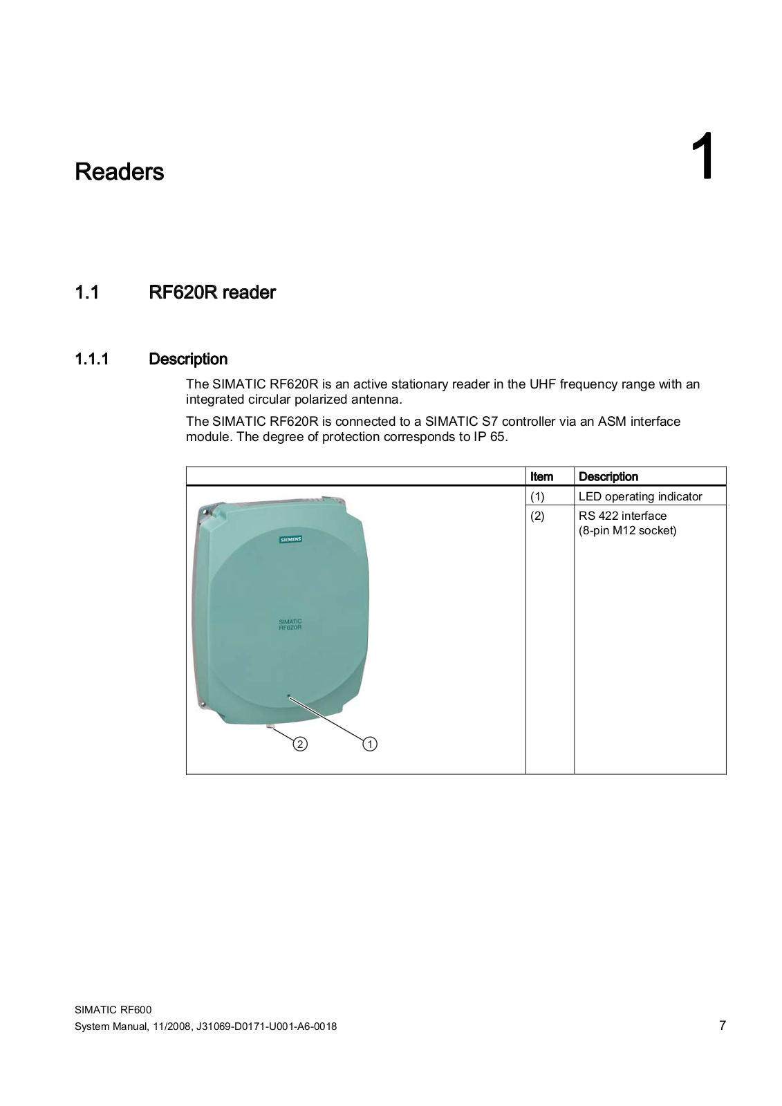
The SIMATIC RF620R is an active stationary reader in the UHF frequency range with an integrated circular polarized antenna.

The SIMATIC RF620R is connected to a SIMATIC S7 controller via an ASM interface module. The degree of protection corresponds to IP 65.

Item Description

(1) LED operating indicator

(2) RS 422 interface (8-pin M12 socket)

SIMATIC RF600

7

System Manual, 11/2008, J31069-D0171-U001-A6-0018

Readers

1.1 RF620R reader

Highlights

The tags are read in accordance with the requirements of the EPCglobal Class 1, Gen 2 and ISO/IEC 18000-6C standards

Supports low-cost SmartLabels as well as reusable, rugged data media

High reading speed: Depending on the function block (multitag mode), many tags can be detected simultaneously (bulk reading), rapidly moving tags are reliably acquired.

The RF620R (ETSI) "6GT2811-5BA00-0AA0" is suitable for the frequency band 865 to 868 MHz UHF (EU, EFTA, Turkey).

IP65 degree of protection for reader

Can be used for a high temperature range

Dense Reader Mode (DRM) for environments in which many readers are operated in close proximity to each other

TIA system interface:

– RS 422

1.1.1.1Ordering data

Device


Order No.


RF620R (ETSI) reader basic unit for EU, EFTA, Turkey

6GT2811-5BA00-0AA0


Accessories

Description


Order No.

Connecting cable

RS 422, M12 plug, 8-pin socket: 2 m

6GT289-0FH20


RS 422, M12 plug, 8-pin socket: 5 m

6GT289-0FH50


RS 422, M12 plug, 8-pin socket: 10 m

6GT289-0FN10


RS 422, M12 plug, 8-pin socket: 20 m

6GT289-0FN20


RS 422, M12 plug, 8-pin socket: 50 m

6GT289-0FN50

Antenna mounting kit

Standard


6GT2890-0AA00

Software & Documentation

CD-ROM


6GT2080-2AA10

8

SIMATIC RF600

System Manual, 11/2008, J31069-D0171-U001-A6-0018

Readers 1.1 RF620R reader

1.1.1.2Status display

The device is equipped with a three colored LED. The LED can be lit in green, red or yellow. The meaning of the indication changes in accordance with the color and state (on, off, flashing) of the LED:

Green

Red LED

Yellow

Meaning

LED


LED


Off

Off

Off

The device is starting up.

Flashing

Off

Off

The device is ready. The antenna is switched off.

On

Off

Off

The device is ready. The antenna is switched on.

Off

Off

On

"With presence": At least one tag is in the field.


"Without presence": Communication with a tag is active.

Off

Flashing

Off

Reader is not active, a serious error has occurred. In addition, this LED also indicates


the fault status through the number of flashing pulses. Reboot (operating voltage Off


→ On is necessary).


The LED flashes once for the 'INACTIVE' status, rebooting is not necessary in this


case.

For more detailed information on the flash codes of the reader see Chapter Error messages and flash codes for RF620R/RF630R (Page Fehler! Textmarke nicht definiert.)

Note

LED not lit yellow?

If the LED does not light up yellow even though a tag is located within the field, common causes are:

Incorrect configuration in the init_run command, or init_run command was not executed (see "Configuration Manual RF620R/RF630R")

Antenna is switched off

A tag is used, that is not compatible with the reader protocol (EPC Global Class 1 Gen 2).

Tag is defective

Reader or antenna has a defect

Tag is not in the field of radiation of the transmit antenna

SIMATIC RF600

9

System Manual, 11/2008, J31069-D0171-U001-A6-0018

Readers

1.1 RF620R reader

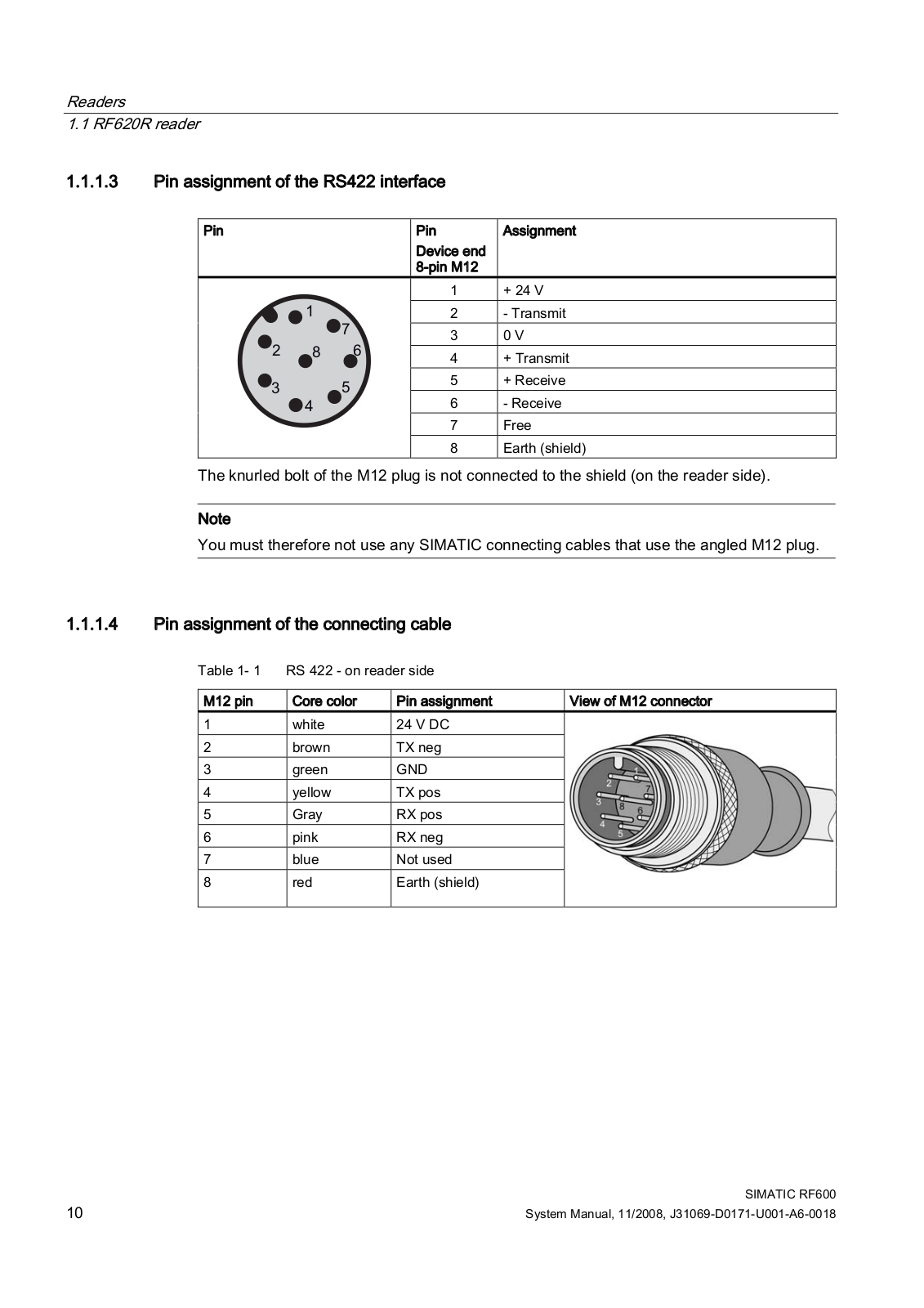
1.1.1.3Pin assignment of the RS422 interface

Pin


Pin

Assignment


Device end


8-pin M12


1

+ 24 V


2

- Transmit


3

0 V


4

+ Transmit


5

+ Receive


6

- Receive


7

Free


8

Earth (shield)

The knurled bolt of the M12 plug is not connected to the shield (on the reader side).

Note

You must therefore not use any SIMATIC connecting cables that use the angled M12 plug.

1.1.1.4Pin assignment of the connecting cable

Table 1- 1 RS 422 - on reader side

M12 pin

Core color

Pin assignment

View of M12 connector

1

white

24 V DC


2

brown

TX neg


3

green

GND


4

yellow

TX pos


5

Gray

RX pos


6

pink

RX neg


7

blue

Not used


8

red

Earth (shield)


10

SIMATIC RF600

System Manual, 11/2008, J31069-D0171-U001-A6-0018

Readers 1.1 RF620R reader

Note

This cable has an 8-pin M12 connector at one end and the other cable end is 'open'. There are 8 color-coded single cores there for connecting to external devices. There are different cable lengths in the product range (3 m to 50 m). Long cables can be reduced if necessary.

Note

For long cables: Adapt supply voltage and data rate accordingly

Note that with long cables in particular, the supply voltage of 24 V DC must always be applied. Note also that the data rate on the serial interface must, if necessary, be reduced. (See "Configuration Manual RF620R/RF630R")

1.1.1.5Grounding connection

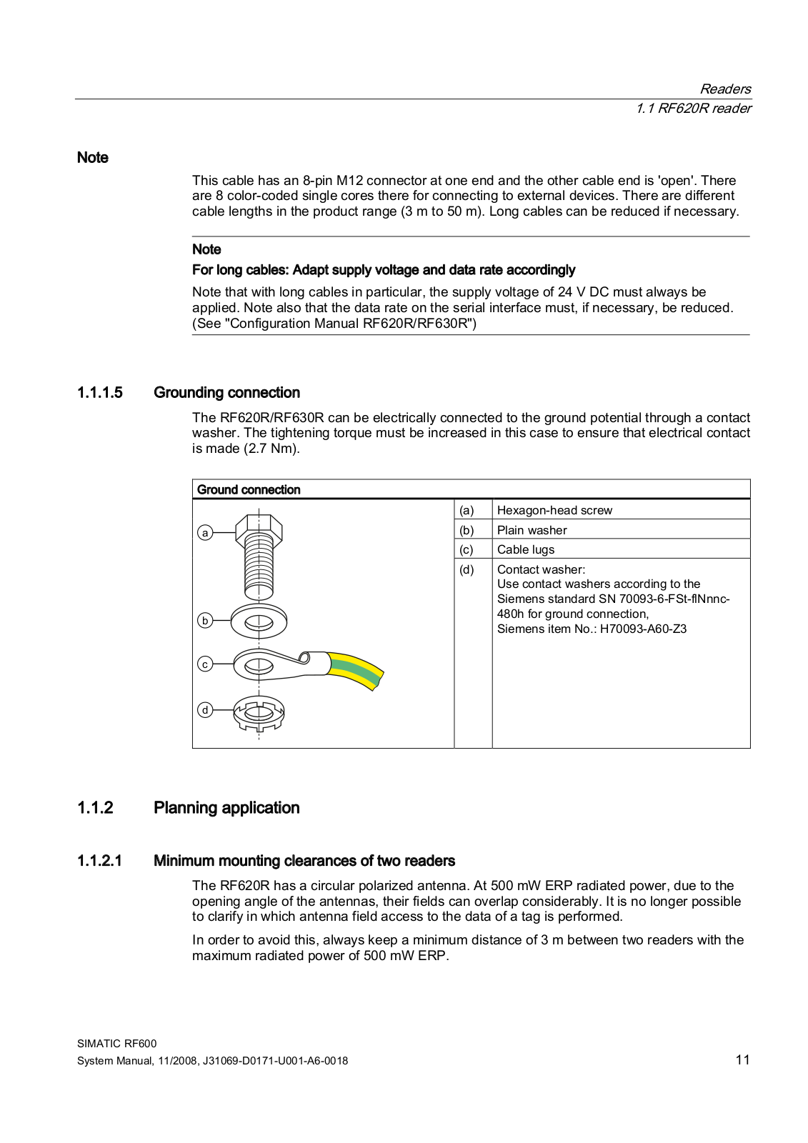
The RF620R/RF630R can be electrically connected to the ground potential through a contact washer. The tightening torque must be increased in this case to ensure that electrical contact is made (2.7 Nm).

Ground connection

D

E

F

G

(a)Hexagon-head screw

(b)Plain washer

(c)Cable lugs

(d)Contact washer:

Use contact washers according to the Siemens standard SN 70093-6-FSt-flNnnc- 480h for ground connection,

Siemens item No.: H70093-A60-Z3

1.1.2Planning application

1.1.2.1Minimum mounting clearances of two readers

The RF620R has a circular polarized antenna. At 500 mW ERP radiated power, due to the opening angle of the antennas, their fields can overlap considerably. It is no longer possible to clarify in which antenna field access to the data of a tag is performed.

In order to avoid this, always keep a minimum distance of 3 m between two readers with the maximum radiated power of 500 mW ERP.

SIMATIC RF600

11

System Manual, 11/2008, J31069-D0171-U001-A6-0018

Readers

1.1 RF620R reader

Dense Reader Mode (DRM)

The readers can also interfere with each other (secondary fields), if the channels (Reader TX, Transponder TX) overlap. In order to prevent a transponder channel overlapping with a reader channel, we recommend that the Dense Reader Mode (DRM) is used.

1.1.2.2Antenna diagram for RF620R (ETSI)

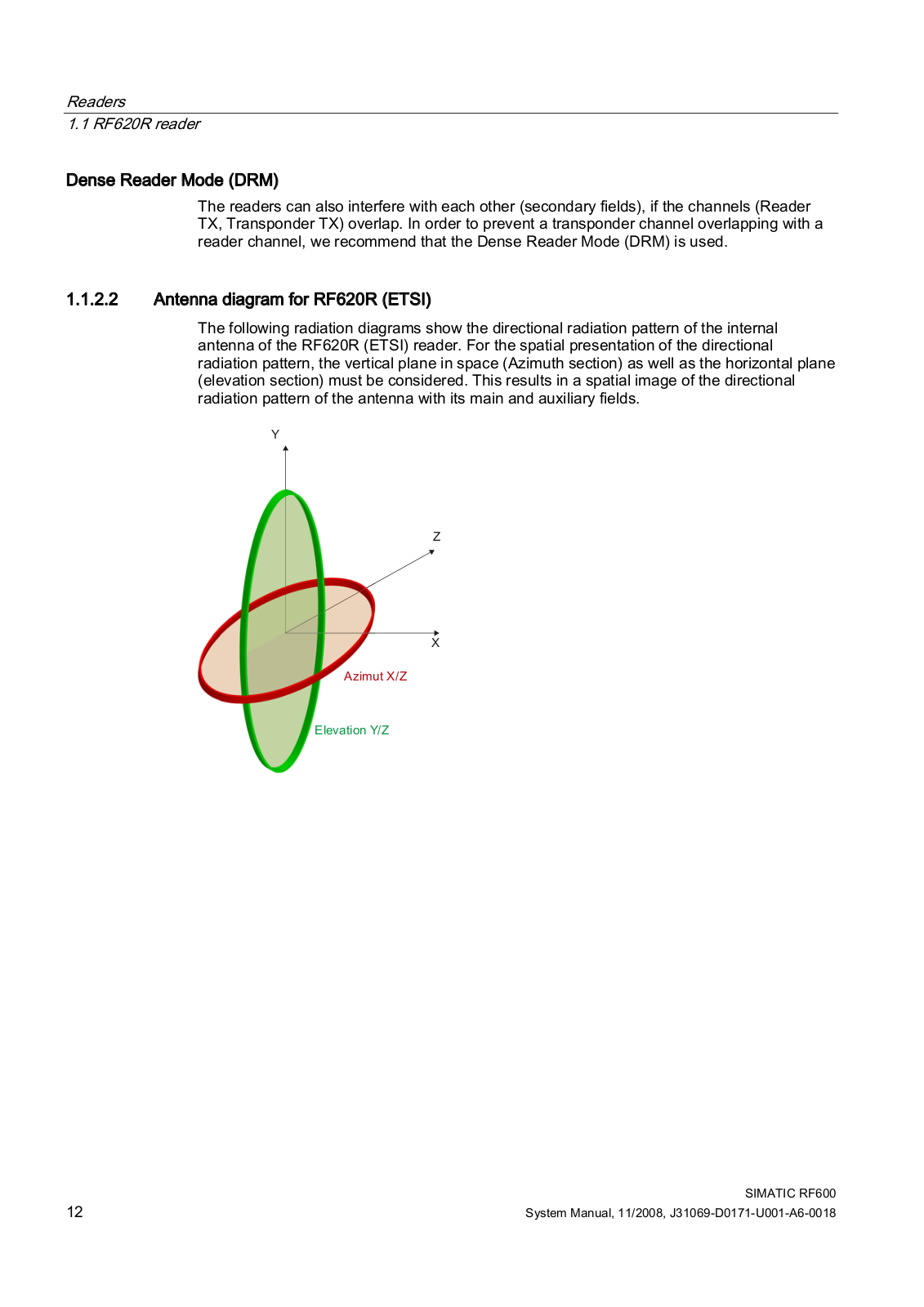
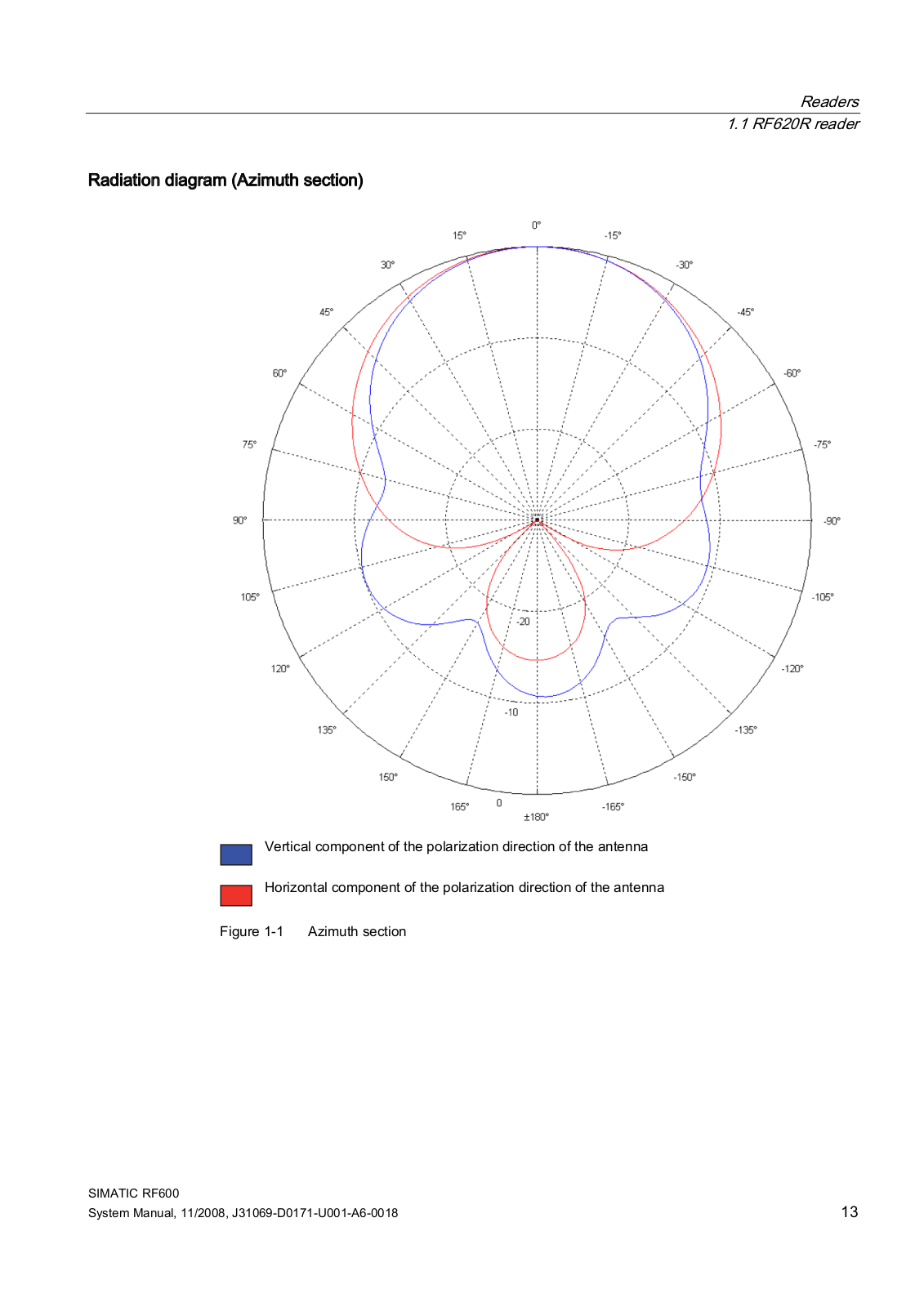
The following radiation diagrams show the directional radiation pattern of the internal antenna of the RF620R (ETSI) reader. For the spatial presentation of the directional radiation pattern, the vertical plane in space (Azimuth section) as well as the horizontal plane (elevation section) must be considered. This results in a spatial image of the directional radiation pattern of the antenna with its main and auxiliary fields.

<

=

;

$]LPXW ; =

(OHYDWLRQ < =

12

SIMATIC RF600

System Manual, 11/2008, J31069-D0171-U001-A6-0018

Readers 1.1 RF620R reader

Radiation diagram (Azimuth section)

9 H U W L F D O F R P S R Q H Q W R I W K H S R O ] D W L R Q G L U H F W L R Q R I W K H D Q W H Q Q D U L

+ R U L ] R Q W D O F R P S R Q H Q W R I W K H S R O D U L ] D W L R Q G L U H F W L R Q R I W K H D Q W H Q Q D

) L J X U H $] L P X W K V H F W L R Q

SIMATIC RF600

13

System Manual, 11/2008, J31069-D0171-U001-A6-0018

Siemens RF620R User Manual

Readers

1.1 RF620R reader

Radiation diagram (elevation section)

9 H U W L F D O F R P S R Q H Q W R I W K H S R O ] D W L R Q G L U H F W L R Q R I W K H D Q W H Q Q D U L

+ R U L ] R Q W D O F R P S R Q H Q W R I W K H S R O D U L ] D W L R Q G L U H F W L R Q R I W K H D Q W H Q Q D

) L J X U H ( O H Y D W L R Q V H F W L R Q

14

SIMATIC RF600

System Manual, 11/2008, J31069-D0171-U001-A6-0018

Loading...
+ 22 hidden pages