

Page 1
Readers
5.2 SIMATIC RF610R
5.2 SIMATIC RF610R
5.2.1 Description
5.2.1.1 Overview
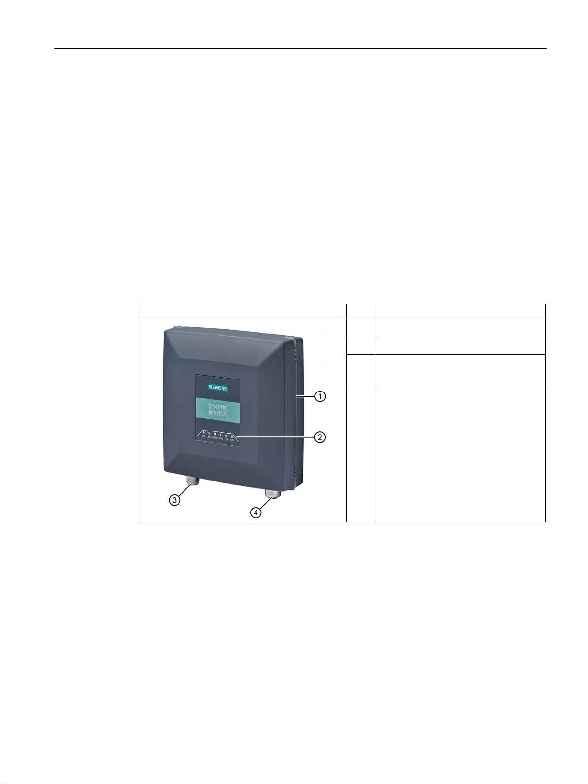
The SIMATIC RF610R is a stationary reader in the UHF frequency band with an integrated
antenna.
The maximum transmit power is 400 mW, the radiant power of the internal antenna is 200 or
250 mW ERP / 400 mW EIRP. The interfaces (Ethernet, power supply) are located on the
lower front edge. These interfaces can be used to connect the reader to the power supply
and a PC for parameter assignment.
The degree of protection is IP67.
Pos. Description
"PRESENCE" LED (PRE)
①
LED operating display
②
Interface to power supply (RS422), 24 V
③
④
1)
: X80 DC24V
DC
(M12, 8-pin)
Ethernet interface, TCP/IP: X1 P1
(M12, 4-pin)
1
) Connection of the readers to the ASM 456 communications module via the RS-422 interface.
SIMATIC RF600
System Manual, 06/2019, J31069-D0171-U001-A22-7618
107
Page 2
Readers
5.2 SIMATIC RF610R
5.2.1.2 Ordering data
Table 5- 2 RF610R ordering data
Product Article number
RF610R (ETSI) 6GT2811-6BC10-0AA0
RF610R (FCC) 6GT2811-6BC10-1AA0
RF610R (CMIIT) 6GT2811-6BC10-2AA0
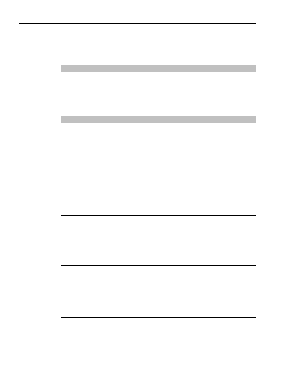
Table 5- 3 Ordering data accessories
Product Article number
SIMATIC antenna holder for RF600 devices 6GT2890-2AB10
Connecting cable and connectors
• Ethernet plug on the reader
FastConnect M12 (IP65)
• Ethernet plug Standard IE
FastConnect RJ45 180 (IP20)
• Industrial Ethernet cable
M12 / M12
• Industrial Ethernet connecting cable
M12-180 / RJ45
• Industrial Ethernet cable
by the meter, green (minimum 20 m)
• Connecting cable reader ↔ CM
M12-180 / M12-180
Wide-range power supply unit for SIMATIC RF systems
• With EU plug
• With UK plug
• With US plug
24 V connecting cable reader ↔ wide-range power supply unit
with plug, 5 m 6GT2891-0PH50
with open ends, 2 m 6GT2891-4EH20
with open ends, 5 m 6GT2891-4EH50
DVD "Ident Systems Software & Documentation" 6GT2080-2AA20
5 m 6XV1870-8AH50
2 m 6XV1871-5TH20
3 m 6XV1871-5TH30
5 m 6XV1871-5TH50
2 m 6GT2891-4FH20
5 m 6GT2891-4FH50
10 m 6GT2891-4FN10
20 m 6GT2891-4FN20
50 m 6GT2891-4FN50
6GK1901-0DB20-6AA0
6GK1901-1BB10-2AA0
6XV1840-2AH10
6GT2898-0AC00
6GT2898-0AC10
6GT2898-0AC20
SIMATIC RF600
System Manual, 06/2019, J31069-D0171-U001-A22-7618
108
Page 3
Readers
5.2 SIMATIC RF610R
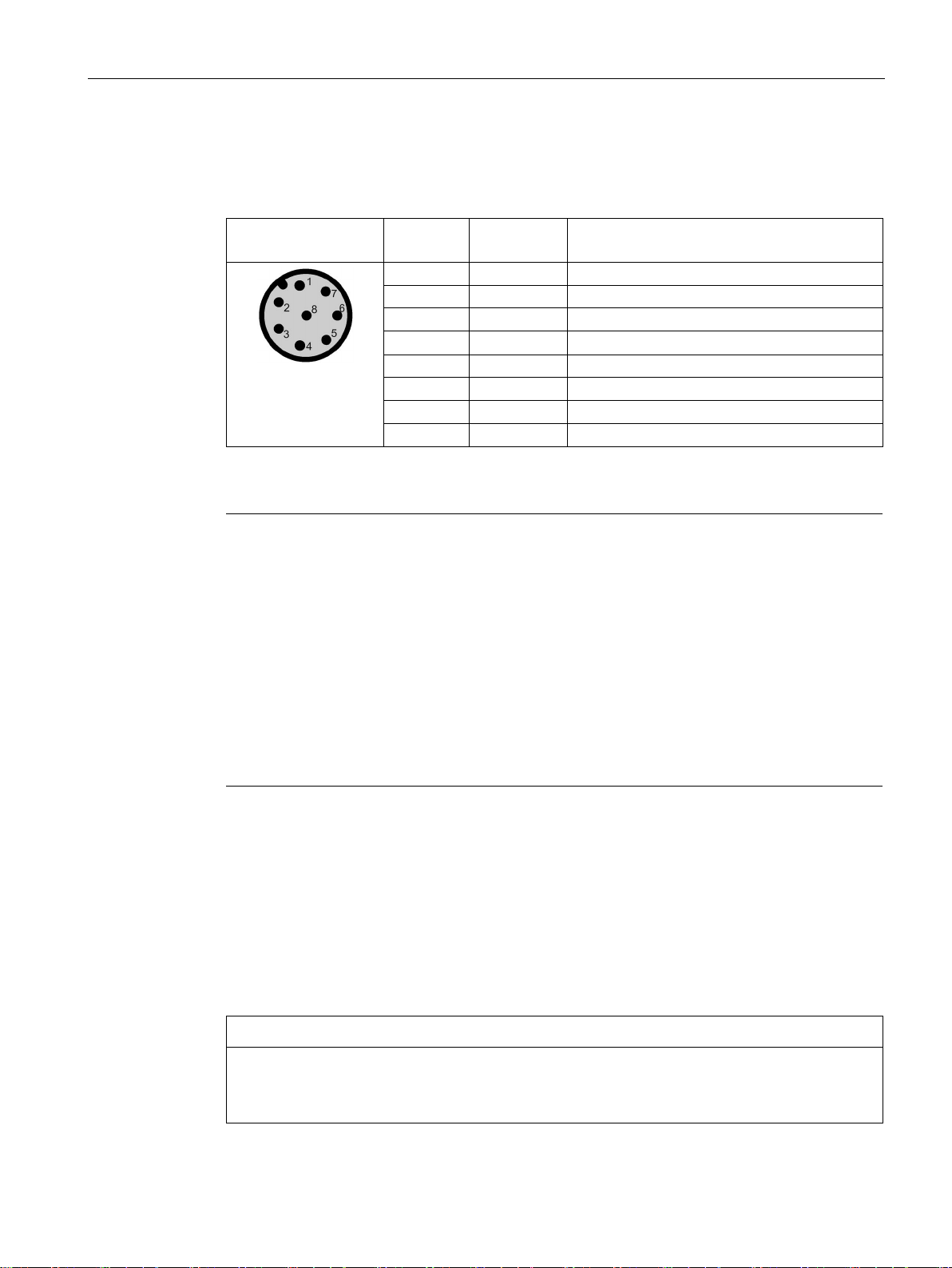
5.2.1.3 Pin assignment of the power supply interface (X80 24VDC)
Table 5- 4 Pin assignment of the RS422 interface (reader end)
View of interface
(M12 socket, 8-pin)
1)
These pins are not required if the reader is operated via Ethernet.
Note
Pin Wire colors Assignment
1 White + 24 V
2 1) Brown - Tx
3 Green 0 V
4 1) Yellow + Tx
5 1) Gray + Rx
6 1) Pink - Rx
7 -- Unassigned
8 -- Earth (shield)
Requirement for external power sources
The reader must only be supplied with power by power supply units that meet the
requirements of LPS (Limited Power Source) and NEC Class 2.
Requirement for external power sources
The reader must only be supplied with power by power supply units that meet the
requirementsof limited power source (LPS) and NEC Class 2.
Spécification des sources de tension externes
L'alimentation du plot de lecture/écriture doit être exclusivement assurée par des blocs
d'alimentation conformes aux spécifications des sources à puissance limitée (Limited Power
Sources LPS) et de NEC class 2.
Notes on connectors and cables
The cables with open cable ends (6GT2891-4EH20, 6GT2891-4EH50) have an 8-pin M12
plug at one end, while the other end of the cable is "open". There are 8 color-coded single
wires there for connecting to external devices.
The product range includes additional cables of the type 6GT2891-4Fxxx (2 to 50 m) with an
M12 connector at both ends. These cables can be used as extension cables. Long cables
can be shortened if necessary.
NOTICE
Insulate unused single wires
Unused single wires must be insulated individually to prevent unwanted connections of
signal lines.
SIMATIC RF600
System Manual, 06/2019, J31069-D0171-U001-A22-7618
109
Page 4
Readers
5.2 SIMATIC RF610R
NOTICE
For long cables: Adapt the power supply and transmission speed
Note that even with long cables, the supply voltage of 24 VDC must always be guaranteed.
Note also that the transmission speed on the serial interface must, if necessary, be
reduced.
SIMATIC standard cables (e.g. 6GT2891-4FN10) have a loop resistance of 160 mOhm /
meter. This results in a voltage drop of 0.8 volts on the 24 V cable for every 10 meters of
connecting cable and with a power requirement of 500 mA. If the power requirement
increases through the use of the digital inputs/outputs, the voltage drop increases
accordingly.
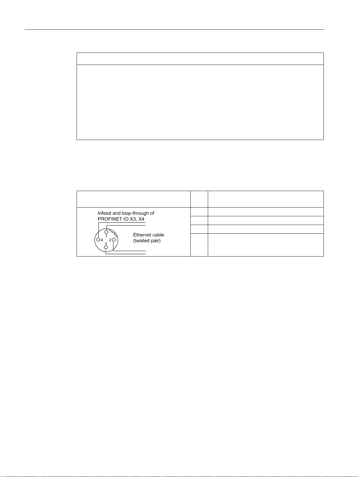
5.2.1.4 Pin assignment of the Industrial Ethernet interface (X1 P1)
Table 5- 5 Pin assignment of the Industrial Ethernet interface (reader end)
View of interface
(M12 socket, 4-pin)
Pin Pin assignment
1 Data line +Tx
2 Data line +Rx
3 Data line -Tx
4 Data line -Rx
5.2.1.5 Ground connection
Due to the potential-free design of the reader, no earthing measures are required.
5.2.2 Planning operation
5.2.2.1 Internal antenna
Minimum mounting clearances of two readers
RF610R has an internal circular antenna. To prevent the antenna fields from overlapping,
always observe the recommended minimum distances between two readers as described in
the section "Reciprocal influence of read points (Page 47)".
SIMATIC RF600
System Manual, 06/2019, J31069-D0171-U001-A22-7618
110
Page 5
Readers
5.2 SIMATIC RF610R
Dense Reader Mode (DRM)
The readers can also interfere with each other (secondary fields), if the channels (Reader
TX, Transponder TX) overlap. In order to prevent a transponder channel overlapping with a
reader channel, we recommend that the Dense Reader Mode (DRM) is used.
Note
Protective cap
If you only use the internal antenna of the reader, we recommend that you close the
external, unused antenna connector on the reader using the protective cap.
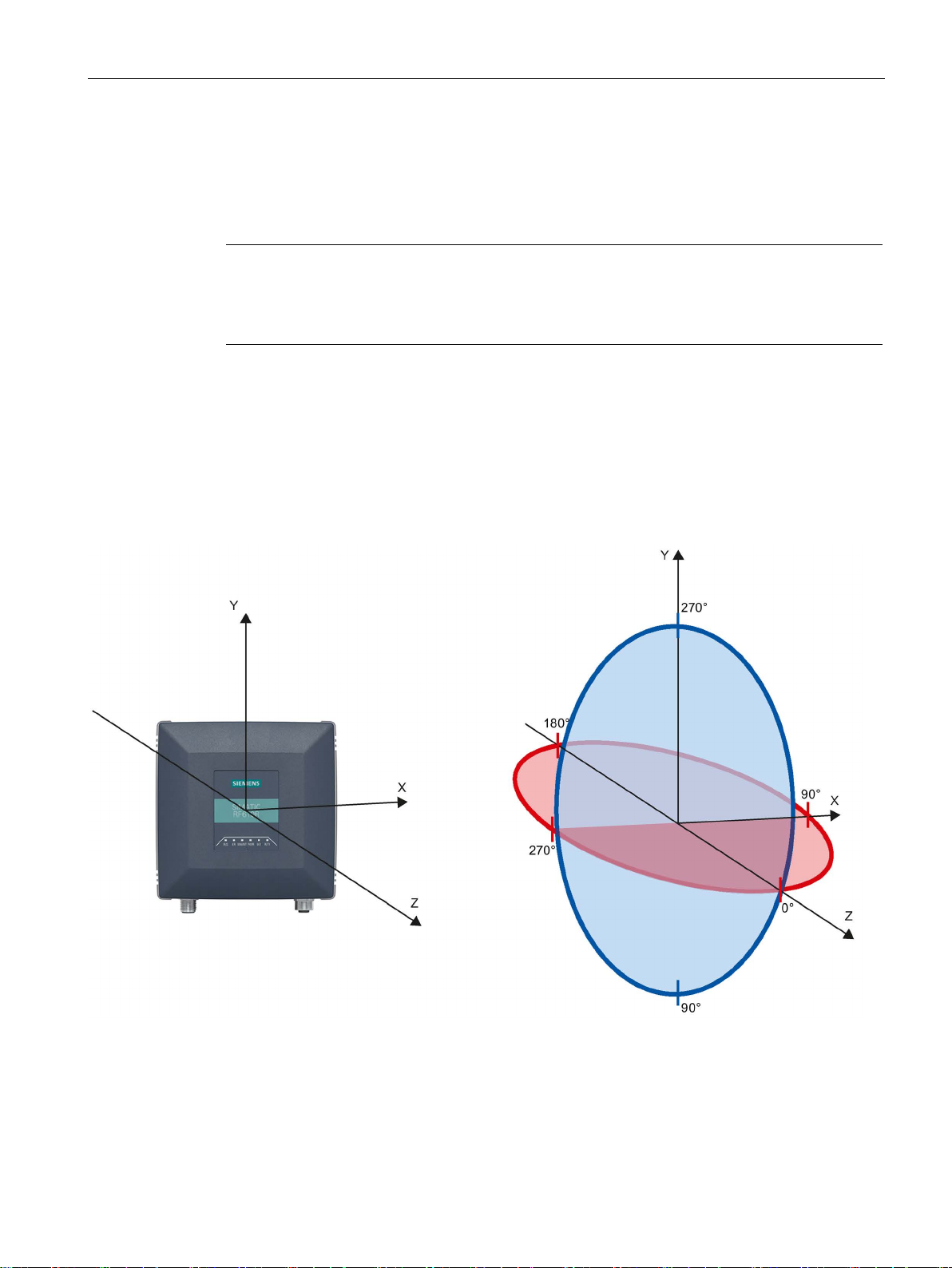
Antenna diagram RF610R (ETSI)
The following radiation diagrams show the directional characteristics of the internal antenna
of the RF610R (ETSI) reader. For the spatial presentation of the directional characteristics,
the horizontal plane (azimuth section) as well as the vertical plane (elevation section) must
be considered. This results in a spatial image of the directional radiation pattern of the
antenna.
Figure 5-1 Reference system
SIMATIC RF600
System Manual, 06/2019, J31069-D0171-U001-A22-7618
111
Page 6

Readers
5.2 SIMATIC RF610R
Radiation diagram (ETSI)
Pattern of the vertical plane of the antenna
Pattern of the horizontal plane of the antenna
Figure 5-2 Directional radiation pattern of RF610R in the ETSI frequency band
SIMATIC RF600
System Manual, 06/2019, J31069-D0171-U001-A22-7618
112
Page 7

Readers
5.2 SIMATIC RF610R
Overview of the antenna parameters
Table 5- 6 Maximum linear electrical aperture angle at 865 MHz:
Polarization (circular)
Azimuth section 100°
Elevation section 100°
Typical antenna gain
in the frequency band 865 to 868 MHz
Antenna axis ratio 2 dB
-1 dBi
You will find more information on the antennas in the section "Guidelines for selecting RFID
UHF antennas (Page 51)".
Antenna diagram for RF610R (FCC)
The following radiation diagrams show the directional characteristics of the internal antenna
of the RF610R (FCC) reader. For the spatial presentation of the directional characteristics,
the horizontal plane (azimuth section) as well as the vertical plane (elevation section) must
be considered. This results in a spatial image of the directional radiation pattern of the
antenna.
Figure 5-3 Reference system
SIMATIC RF600
System Manual, 06/2019, J31069-D0171-U001-A22-7618
113
Page 8

Readers
5.2 SIMATIC RF610R
Radiation diagram (FCC)
Pattern of the vertical plane of the antenna
Pattern of the horizontal plane of the antenna
Figure 5-4 Directional radiation pattern of RF610R in the FCC frequency band
SIMATIC RF600
System Manual, 06/2019, J31069-D0171-U001-A22-7618
114
Page 9

Readers
5.2 SIMATIC RF610R
Overview of the antenna parameters
Table 5- 7 Maximum linear electrical aperture angle at 915 MHz:
Polarization (circular)
Azimuth section 100°
Elevation section 100°
Typical antenna gain
in the frequency band 902 to 928 MHz
Antenna axis ratio 2 dB
0 dBi
You will find more information on the antennas in the section "Guidelines for selecting RFID
UHF antennas (Page 51)".
5.2.2.2 Interpretation of radiation patterns
You can find detailed information on the interpretation in the section "Interpretation of
radiation patterns (Page 215)".
5.2.3 Installation / mounting
Requirement
Mounting/installing the device
NOTICE
Close unused connectors
Note that the readers only have the specified degree of protection when all connectors are
in use or when unused connectors are closed with the protective caps.
CAUTION
Emitted radiation
The transmitter complies with the requirements of Health Canada and the FCC limit values
for subjecting persons to HF radiation, provided that a minimum spacing of 26 cm exists
between antenna and person. When the antennas are installed, you must therefore ensure
that a minimum spacing of 26 cm is maintained between personnel and antennas.
You can mount the reader in the following ways:
● directly on a flat surface using the VESA 100 mounting system (torque ≃ 1.5 Nm).
The positions of the mounting holes for the device are shown in the section Dimension
drawing (Page 120).
SIMATIC RF600
System Manual, 06/2019, J31069-D0171-U001-A22-7618
115
Page 10

Readers
5.2 SIMATIC RF610R
5.2.4 Configuration/integration
An Ethernet interface is available for integrating the device into system
environments/networks. RF610R can be configured via the Ethernet interface and with direct
connection to the PC. You can configure and program the reader using the following tools:
● STEP 7 Basic/Professional (TIA Portal)
● or via EtherNet/IP
● Web Based Management (WBM)
● OPC UA or XML based user applications
Note that configuration in parallel is not possible using different tools. Simple process
controls (e.g. a traffic signal) can be implemented directly using the reader via the digital
input/output.
Figure 5-5 Overview: Configuration of RF610R readers
SIMATIC RF600
System Manual, 06/2019, J31069-D0171-U001-A22-7618
116
Page 11

Readers
5.2 SIMATIC RF610R
5.2.5 Technical specifications
Table 5- 8 Technical specifications of the RF610R reader
6GT2811-6BC10-xAA0
Product type designation SIMATIC RF610R
Radio frequencies
Operating frequency
• ETSI • 865 to 868 MHz
• FCC • 902 to 928 MHz
• CMIIT • 920 to 925 MHz
Transmit power
• ETSI • 3 ... 400 mW
• FCC • 3 ... 400 mW
• CMIIT • 3 ... 400 mW
Maximum radiated power
• ETSI • 200 mW ERP
• FCC • 400 mW EIRP
• CMIIT • 250 mW ERP
Electrical data
Range (internal antenna)
• ETSI • ≤ 1 m
• FCC • ≤ 1 m
• CMIIT • ≤ 1 m
Protocol ISO 18000-62/-63
Transmission speed ≤ 300 kbps
Frequency accuracy ≤ ±10 ppm
Channel spacing
• ETSI • 600 kHz
• FCC • 500 kHz
• CMIIT • 250 kHz
Modulation methods ASK: DSB modulation & PR-ASK modulation
encoding, Manchester or Pulse Interval (PIE)
Multitag capability Yes
SIMATIC RF600
System Manual, 06/2019, J31069-D0171-U001-A22-7618
117
Page 12

Readers
5.2 SIMATIC RF610R
6GT2811-6BC10-xAA0
Typical transmission time per byte
• Write access • 2 ms
• Read access • 0.15 ms
Supply voltage 24 VDC (20 ... 30 VDC)
Maximum permitted current consumption 0.3 A
Current consumption (on standby), typical
• 20 V input voltage on the reader • 200 mA / 4 W
• 24 V input voltage on the reader • 170 mA / 4.1 W
• 30 V input voltage on the reader • 150 mA / 4.2 W
Current consumption (at 400 mW transmit power), typical
• 20 V input voltage on the reader • 260 mA / 5.2 W
• 24 V input voltage on the reader • 220 mA / 5.3 W
• 30 V input voltage on the reader • 170 mA / 5.1 W
1)
Interfaces
Power supply 1x M12 (8-pin)
Ethernet interface 1x M12 (4-pin), 100 Mbps
Mechanical specifications
Material Pocan (silicone-free)
Color TI-Grey
Permitted ambient conditions
Ambient temperature
• During operation • -25 ... +55 °C
• During transportation and storage • -40 ... +85 °C
Conditions relating to UL approval
• for indoor use only (dry location)
• Mounting height shall be equal or less than 2
m (MS1 classification according UL/IEC
62368-1).
La hauteur de montage doit être égale ou
inférieure à 2 m (classification MS1 selon CEI
62368-1).
Degree of protection IP67
Shock resistant to EN 60068-2-27 25.5 g 2)
Vibration to EN 60068-2-6 3.1 g 2)
SIMATIC RF600
System Manual, 06/2019, J31069-D0171-U001-A22-7618
118
Page 13

Readers
5.2 SIMATIC RF610R
6GT2811-6BC10-xAA0
Design, dimensions and weight
Dimensions (W × H × D) 140.5 × 133 × 45 mm
Weight 370 g
Type of mounting VESA 100
4x screws M4 (≃ 1.5 Nm)
Operation indicator 6 LEDs
Status display 1 LED (enclosure, all-round)
Standards, specifications, approvals
Proof of suitability EN 301 489-1 V2.2.0 / EN 301 489-3 V2.1.1 / EN
302 208 V3.1.1
FCC CFR 47, Part 15 section 15.247
MTBF 29 years
1)
All supply and signal voltages must be safety extra low voltage (SELV/PELV according to
EN 60950). All voltage sources must meet the requirements of limited power sources (LPS) and
NEC Class 2.
Note that, depending on the power consumption, using extension cables > 20 m (6GT28914FN50) may lead to a voltage drop on the reader. This voltage drop can mean that the necessary
minimum voltage on the reader is below the required 20 V.
2)
The values for shock and vibration are maximum values and must not be applied continuously.
These values only apply to mounting using screws.
SIMATIC RF600
System Manual, 06/2019, J31069-D0171-U001-A22-7618
119
Page 14

Readers
5.2 SIMATIC RF610R
5.2.6 Dimension drawing
Figure 5-6 Dimension drawing RF610R
All dimensions in mm (± 0.5 mm tolerance)
SIMATIC RF600
System Manual, 06/2019, J31069-D0171-U001-A22-7618
120
Page 15

Readers
5.2 SIMATIC RF610R
5.2.7 Certificates and approvals
5.2.7.1 CE mark
Note
Marking on the readers according to specific approval
The certificates and approvals listed here apply only if the corresponding mark is found on
the readers.
Table 5- 9 6GT2811-6BC10-0AA0
Labeling Description
Conformity with the RED directive 2014/53/EU
Conformity with the RoHS directive 2011/65/EU
5.2.7.2 Country-specific certifications
Table 5- 10 6GT2811-6BC10-1AA0
Labeling Description
Federal Communications
Commission
Industry Canada Radio
Standards Specifications
Table 5- 11 6GT2811-6BC10-2AA0
Standard
CMIIT Certification China radio approval
FCC CFR 47, Part 15 section 15.247
Radio Frequency Interference Statement
This equipment has been tested and found to comply with the limits
for a Class B digital device, pursuant to Part 15 of the FCC Rules.
FCC ID: NXW-RF610R
RSS-247 Issue 2
IC: 267X-RF610R
This product is UL-certified for the USA and Canada.
It meets the following safety standard(s):
UL/IEC 62368-1, 2nd Ed
CAN/CSA C22.2 No. 62368-1-14, 2nd Ed
Audio/video, information and communication technology equipment -
Part 1: Safety requirements
Marking on the reader: CMIIT ID: 2018DJxxxx
SIMATIC RF600
System Manual, 06/2019, J31069-D0171-U001-A22-7618
121
Page 16

Readers
5.2 SIMATIC RF610R
5.2.7.3 FCC information
Siemens SIMATIC RF610R (FCC): 6GT2811-6BC10-1AA0
FCC ID: NXW-RF610R
This device complies with part 15 of the FCC rules. Operation is subject to the following two
conditions:
(1) This device may not cause harmful interference, and
(2) this device must accept any interference received, including interference that may cause
undesired operation.
Caution
Any changes or modifications not expressly approved by the party responsible for
compliance could void the user's authority to operate the equipment.
Note
This equipment has been tested and found to comply with the limits for a Class B digital
device, pursuant to part 15 of the FCC Rules.
These limits are designed to provide reasonable protection against harmful interference
when the equipment is operated in a commercial environment. This equipment generates,
uses, and can radiate radio frequency energy and, if not installed and used in accordance
with the instruction manual, may cause harmful interference to radio communications.
Operation of this equipment in a residential area is likely to cause harmful interference in
which case the user will be required to correct the interference at his own expense.
FCC Notice
To comply with FCC part 15 rules in the United States, the system must be professionally
installed to ensure compliance with the Part 15 certification.
It is the responsibility of the operator and professional installer to ensure that only certified
systems are deployed in the United States. The use of the system in any other combination
(such as co-located antennas transmitting the same information) is expressly forbidden.
FCC Exposure Information
To comply with FCC RF exposure compliance requirements, the antennas used for this
transmitter must be installed to provide a separation distance of at least 20 cm from all
persons and must not be co-located or operating in conjunction with any other antenna or
transmitter.
SIMATIC RF600
System Manual, 06/2019, J31069-D0171-U001-A22-7618
122
 Loading...