

Page 1
Any changes or modifications not expressly approved by the party responsible for compliance could void the user's authority to operate the
equipment
SIMATIC Sensors
RFID systems
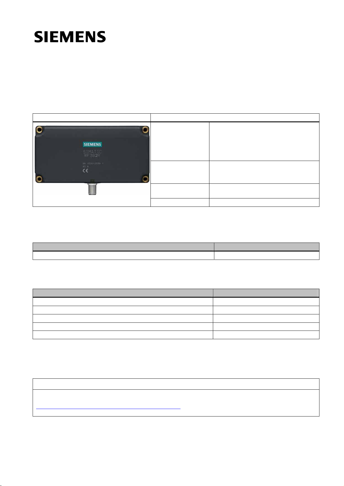
SIMATIC RF382R Scanmode
Operating Instructions (Compact)
Characteristics
RF382R Scanmode Characteristics
Operating range Suitable for high speeds, e.g. in
Antenna field Designed for transponders that are directed
Read distance Depending on transponder; see Field data for
Degree of protection IP67
● Suspension conveyor systems
● Assembly lines
● Production
● Order picking
sideways past the long side of the antenna.
See Chapter Transmission window (Page 3)
MDS and SLG (Page 6)
Ordering data
Table 1 RF382R Scanmode ordering data
Product Order No.
RF382R Scanmode 6GT2801-3AB20-0AX0
Table 2 RF382R Scanmode ordering data for accessories
Accessories Order No.
Simatic Sensors connecting cable, length: 5 m 6GT2891-0FH50
Simatic Sensors RF380R connecting cable RS232 6GT2891-0KH50
Wide-range power supply 24 V, 4 A, with Euro plug 6GT2898-0AA00
Wide-range power supply 24 V, 4 A, with UK plug 6GT2898-0AA10
Wide-range power supply 24 V, 4 A, with US plug 6GT2898-0AA20
Safety instructions for the device/system
NOTICE
This device/system may only be used for the application instances that have been described in the catalog and the
technical documentation "SIMATIC RF300 System Manual
(http://support.automation.siemens.com/WW/view/en/21738946
components recommended and/or approved by Siemens.
)" and only in combination with third-party devices and
© Siemens Ⓟ 2009
J31069-D0214-U001-A1-7618, 10/2009
1
 Loading...