

Page 1

___________________
___________________
___________________
___________________
___________________
___________________
___________________
___________________
___________________
___________________
___________________
SIMATIC Ident
RFID systems
SIMATIC RF300
System Manual
07/2017
C79000
Introduction
1
Safety information
2
System overview
3
Planning the RF300 system
4
Readers
5
Antennas
6
RF300 transponder
7
ISO transponder
8
System integration
9
System diagnostics
10
Appendix
A
-G8976-C345-07
Page 2

Siemens AG
Division Process Industries and Drives
Postfach 48 48
90026 NÜRNBERG
GERMANY
Ⓟ
Copyright © Siemens AG 2005 - 2017.
All rights reserved
Legal information
Warning notice system
DANGER
indicates that death or severe personal injury will result if proper precautions are not taken.
WARNING
indicates that death or severe personal injury may result if proper precautions are not taken.
CAUTION
indicates that minor personal injury can result if proper precautions are not taken.
NOTICE
indicates that property damage can result if proper precautions are not taken.
Qualified Personnel
personnel qualified
Proper use of Siemens products
WARNING
Siemens products may only be used for the applications described in the catalog and in the relevant technical
ambient conditions must be complied with. The information in the relevant documentation must be observed.
Trademarks
Disclaimer of Liability
This manual contains notices you have to observe in order to ensure your personal safety, as well as to prevent
damage to property. The notices referring to your personal safety are highlighted in the manual by a safety alert
symbol, notices referring only to property damage have no safety alert symbol. These notices shown below are
graded according to the degree of danger.
If more than one degree of danger is present, the warning notice representing the highest degree of danger will
be used. A notice warning of injury to persons with a safety alert symbol may also include a warning relating to
property damage.
The product/system described in this documentation may be operated only by
task in accordance with the relevant documentation, in particular its warning notices and safety instructions.
Qualified personnel are those who, based on their training and experience, are capable of identifying risks and
avoiding potential hazards when working with these products/systems.
Note the following:
documentation. If products and components from other manufacturers are used, these must be recommended
or approved by Siemens. Proper transport, storage, installation, assembly, commissioning, operation and
maintenance are required to ensure that the products operate safely and without any problems. The permissible
All names identified by ® are registered trademarks of Siemens AG. The remaining trademarks in this publication
may be trademarks whose use by third parties for their own purposes could violate the rights of the owner.
We have reviewed the contents of this publication to ensure consistency with the hardware and software
described. Since variance cannot be precluded entirely, we cannot guarantee full consistency. However, the
information in this publication is reviewed regularly and any necessary corrections are included in subsequent
editions.
for the specific
07/2017 Subject to change
Page 3

Table of contents
1 Introduction ........................................................................................................................................... 15
2 Safety information ................................................................................................................................. 19
3 System overview ................................................................................................................................... 23
4 Planning the RF300 system .................................................................................................................. 39
1.1 Navigating in the system manual ............................................................................................ 15
1.2 Preface .................................................................................................................................... 15
3.1 RFID systems ......................................................................................................................... 23
3.2 SIMATIC RF300 ...................................................................................................................... 24
3.2.1 System overview of SIMATIC RF300 ..................................................................................... 24
3.2.2 RFID components and their function ...................................................................................... 25
3.2.3 Application areas of RF300 .................................................................................................... 33
3.3 System configuration .............................................................................................................. 34
3.3.1 Overview ................................................................................................................................. 34
3.3.2 Assembly line example: Use of RF300 transponders ............................................................. 34
3.3.3 Example of container and cardboard container handling: Use of ISO transponders ............. 36
4.1 Fundamentals of application planning .................................................................................... 39
4.1.1 Selection criteria for SIMATIC RF300 components ................................................................ 39
4.1.2 Transmission window and read/write distance ....................................................................... 39
4.1.3 Width of the transmission window .......................................................................................... 42
4.1.4 Impact of secondary fields ...................................................................................................... 43
4.1.5 Setup help of the readers of the second generation ............................................................... 46
4.1.6 Permissible directions of motion of the transponder ............................................................... 47
4.1.7 Operation in static and dynamic mode ................................................................................... 47
4.1.8 Dwell time of the transponder ................................................................................................. 49
4.1.9 Communication between communications module, reader and transponder ........................ 50
4.2 Field data for transponders, readers and antennas ................................................................ 51
4.2.1 Field data of RF300 transponders .......................................................................................... 52
4.2.2 Field data of ISO transponders (MDS D) ................................................................................ 56
4.2.3 Field data of ISO transponders (MDS E) ................................................................................ 61
4.2.4 Minimum clearances ............................................................................................................... 64
4.3 Installation guidelines.............................................................................................................. 67
4.3.1 Overview ................................................................................................................................. 67
4.3.2 Reduction of interference due to metal ................................................................................... 67
4.3.3 Effects of metal on different transponders and readers .......................................................... 70
4.3.4 Impact on the transmission window by metal ......................................................................... 70
4.3.4.1 Impact on the transmission window by metal ......................................................................... 71
4.3.4.2 RF340R ................................................................................................................................... 75
4.3.4.3 RF350R ................................................................................................................................... 79
4.3.4.4 RF380R ................................................................................................................................... 93
4.3.4.5 RF382R ...................................................................................................................................
96
SIMATIC RF300
System Manual, 07/2017, C79000-G8976-C345-07
3
Page 4

Table of contents
5 Readers ............................................................................................................................................... 123
4.4 Chemical resistance of the readers and transponders .......................................................... 97
4.4.1 Readers .................................................................................................................................. 97
4.4.1.1 Overview of the readers and their housing materials ............................................................ 97
4.4.1.2 Polyamide 12 ......................................................................................................................... 97
4.4.2 Transponder ........................................................................................................................... 99
4.4.2.1 Overview of the transponders and their housing materials ................................................... 99
4.4.2.2 Polyamide 6 and Polyamide 6.6 GF30 ................................................................................ 101
4.4.2.3 Polyamide 12 ....................................................................................................................... 102
4.4.2.4 Polyphenylene sulfide (PPS) ............................................................................................... 104
4.4.2.5 Polycarbonate (PC) .............................................................................................................. 105
4.4.2.6 Polyvinyl chloride (PVC) ...................................................................................................... 106
4.4.2.7 Epoxy resin .......................................................................................................................... 106
4.5 Guidelines for electromagnetic compatibility (EMC) ............................................................ 109
4.5.1 Overview .............................................................................................................................. 109
4.5.2 What does EMC mean? ....................................................................................................... 110
4.5.3 Basic rules ............................................................................................................................ 111
4.5.4 Propagation of electromagnetic interference ....................................................................... 112
4.5.5 Cabinet configuration ........................................................................................................... 116
4.5.6 Prevention of interference sources ...................................................................................... 119
4.5.7 Equipotential bonding .......................................................................................................... 120
4.5.8 Cable shielding..................................................................................................................... 121
5.1 SIMATIC RF310R ................................................................................................................ 124
5.1.1 Features ............................................................................................................................... 124
5.1.2 RF310R ordering data ......................................................................................................... 124
5.1.3 Pin assignment RF310R with RS-422 interface .................................................................. 125
5.1.4 LED operating display .......................................................................................................... 125
5.1.5 Ensuring reliable data exchange .......................................................................................... 125
5.1.6 Metal-free area ..................................................................................................................... 126
5.1.7 Minimum distance between RF310R readers ...................................................................... 126
5.1.8 Technical specifications ....................................................................................................... 127
5.1.9 Approvals ............................................................................................................................. 129
5.1.10 Dimension drawing .............................................................................................................. 130
5.2 SIMATIC RF310R with Scanmode ...................................................................................... 131
5.2.1 Features ............................................................................................................................... 131
5.2.2 Ordering data for RF310R with Scanmode .......................................................................... 131
5.2.3 Pin assignment RF310R special version Scanmode RS-422 interface ............................... 132
5.2.4 LED operating display .......................................................................................................... 132
5.2.5 Ensuring reliable data exchange .......................................................................................... 132
5.2.6 Metal-free area ..................................................................................................................... 133
5.2.7 Minimum distance between several readers ....................................................................... 133
5.2.8 Technical specifications ....................................................................................................... 134
5.2.9 Approvals ............................................................................................................................. 135
5.2.10 Dimension drawing .............................................................................................................. 136
5.3 SIMATIC RF310R - 2nd generation ..................................................................................... 137
5.3.1 Features ...............................................................................................................................
137
5.3.2 Ordering data ....................................................................................................................... 137
5.3.3 Pin assignment of the RS-422 interface .............................................................................. 138
5.3.4 LED operating display .......................................................................................................... 138
5.3.5 Ensuring reliable data exchange .......................................................................................... 139
SIMATIC RF300
4 System Manual, 07/2017, C79000-G8976-C345-07
Page 5

Table of contents
5.3.6 Metal-free area ...................................................................................................................... 139
5.3.7 Minimum distance between RF310R readers ...................................................................... 140
5.3.8 Technical specifications ........................................................................................................ 141
5.3.9 Approvals .............................................................................................................................. 142
5.3.10 Dimension drawing ............................................................................................................... 144
5.3.11 Using the reader in hazardous area ..................................................................................... 144
5.3.11.1 Using the reader in hazardous area for gases ..................................................................... 148
5.3.11.2 Using the reader in hazardous area for dust ........................................................................ 148
5.3.11.3 Installation and operating conditions for hazardous areas: .................................................. 149
5.4 SIMATIC RF340R/RF350R .................................................................................................. 150
5.4.1 SIMATIC RF340R ................................................................................................................. 150
5.4.1.1 Features ................................................................................................................................ 150
5.4.1.2 Ordering data for RF340R .................................................................................................... 150
5.4.1.3 Pin assignment of RF340R RS422 interface ........................................................................ 151
5.4.1.4 LED operating display ........................................................................................................... 151
5.4.1.5 Ensuring reliable data exchange .......................................................................................... 151
5.4.1.6 Metal-free area ...................................................................................................................... 152
5.4.1.7 Minimum distance between RF340R readers ...................................................................... 152
5.4.1.8 Technical specifications ........................................................................................................ 153
5.4.1.9 Approvals .............................................................................................................................. 155
5.4.1.10 Dimension drawing ............................................................................................................... 156
5.4.2 SIMATIC RF350R ................................................................................................................. 157
5.4.2.1 Features ................................................................................................................................
157
5.4.2.2 Ordering data for RF350R .................................................................................................... 157
5.4.2.3 Pin assignment of RF350R RS422 interface ........................................................................ 158
5.4.2.4 LED operating display ........................................................................................................... 158
5.4.2.5 Ensuring reliable data exchange .......................................................................................... 158
5.4.2.6 Metal-free area ...................................................................................................................... 158
5.4.2.7 Technical specifications ........................................................................................................ 159
5.4.2.8 Approvals .............................................................................................................................. 161
5.4.2.9 Dimension drawing ............................................................................................................... 162
5.4.3 Use of the reader in hazardous areas .................................................................................. 163
5.4.3.1 Use of the readers in hazardous areas for gases ................................................................. 164
5.4.3.2 Use of the readers in hazardous areas for dusts .................................................................. 164
5.4.3.3 Installation and operating conditions for the hazardous area ............................................... 165
5.5 SIMATIC RF340R/RF350R - 2nd generation ....................................................................... 166
5.5.1 SIMATIC RF340R - 2nd generation ...................................................................................... 166
5.5.1.1 Features ................................................................................................................................ 166
5.5.1.2 Ordering data ........................................................................................................................ 166
5.5.1.3 Pin assignment of the RS-422 interface ............................................................................... 167
5.5.1.4 LED operating display ........................................................................................................... 167
5.5.1.5 Ensuring reliable data exchange .......................................................................................... 167
5.5.1.6 Metal-free area ...................................................................................................................... 168
5.5.1.7 Minimum distance between RF340R readers ...................................................................... 168
5.5.1.8 Technical specifications ........................................................................................................ 169
5.5.1.9 Approvals .............................................................................................................................. 171
5.5.1.10 Dimension drawing ............................................................................................................... 172
5.5.2 SIMATIC RF350R - 2nd generation ...................................................................................... 173
5.5.2.1 Features ................................................................................................................................ 173
5.5.2.2 Ordering data ........................................................................................................................ 173
5.5.2.3 Pin assignment of the RS-422 interface ............................................................................... 174
SIMATIC RF300
System Manual, 07/2017, C79000-G8976-C345-07
5
Page 6

Table of contents
5.5.2.4 LED operating display .......................................................................................................... 174
5.5.2.5 Ensuring reliable data exchange .......................................................................................... 174
5.5.2.6 Metal-free area ..................................................................................................................... 175
5.5.2.7 Technical specifications ....................................................................................................... 175
5.5.2.8 Approvals ............................................................................................................................. 177
5.5.2.9 Dimension drawing .............................................................................................................. 178
5.5.3 Using the readers in a hazardous area ................................................................................ 179
5.5.3.1 Using the reader in hazardous area for gases ..................................................................... 182
5.5.3.2 Using the reader in hazardous area for dust ....................................................................... 182
5.5.3.3 Installation and operating conditions for hazardous areas: ................................................. 183
5.6 SIMATIC RF380R ................................................................................................................ 184
5.6.1 Features ............................................................................................................................... 184
5.6.2 RF380R ordering data ......................................................................................................... 184
5.6.3 Pin assignment of RF380R RS-232/RS-422 interface......................................................... 184
5.6.4 LED operating display .......................................................................................................... 185
5.6.5 Ensuring reliable data exchange .......................................................................................... 185
5.6.6 Metal-free area ..................................................................................................................... 186
5.6.7 Minimum distance between RF380R readers ...................................................................... 186
5.6.8 Technical specifications ....................................................................................................... 187
5.6.9 Approvals ............................................................................................................................. 189
5.6.10 Dimension drawing .............................................................................................................. 190
5.6.11 Use of the reader in a hazardous ......................................................................................... 190
5.6.11.1 Use of the reader in a hazardous area ................................................................................ 190
5.6.11.2 Use of the reader in hazardous areas for gases .................................................................. 191
5.6.11.3 Installation and operating conditions for hazardous areas: ................................................. 192
5.7 SIMATIC RF380R with Scanmode ...................................................................................... 193
5.7.1 Features ............................................................................................................................... 193
5.7.2 Ordering data for RF380R with Scanmode .......................................................................... 193
5.7.3 Pin assignment RF380R Scanmode RS-232 interface........................................................ 194
5.7.4 LED operating display .......................................................................................................... 194
5.7.5 Ensuring reliable data exchange .......................................................................................... 194
5.7.6 Metal-free area ..................................................................................................................... 195
5.7.7 Minimum distance between several RF380R Scanmode readers ....................................... 195
5.7.8 Technical specifications ....................................................................................................... 196
5.7.9 Approvals ............................................................................................................................. 197
5.7.10 Certificates and Approvals ................................................................................................... 198
5.7.11 Dimension drawing .............................................................................................................. 199
5.8 SIMATIC RF380R - 2nd generation ..................................................................................... 200
5.8.1 Features ............................................................................................................................... 200
5.8.2 RF380R ordering data ......................................................................................................... 200
5.8.3 Pin assignment of RF380R RS-232/RS-422 interface......................................................... 201
5.8.4 LED operating display .......................................................................................................... 201
5.8.5 Ensuring reliable data exchange .......................................................................................... 202
5.8.6 Metal-free area ..................................................................................................................... 202
5.8.7 Minimum distance between RF380R readers ...................................................................... 203
5.8.8 Technical specifications ....................................................................................................... 204
5.8.9 Approvals .............................................................................................................................
205
5.8.10 Dimension drawing .............................................................................................................. 207
5.8.11 Using the reader in hazardous area..................................................................................... 207
5.8.11.1 Using the reader in hazardous area for gases ..................................................................... 210
5.8.11.2 Using the reader in hazardous area for dust ....................................................................... 211
SIMATIC RF300
6 System Manual, 07/2017, C79000-G8976-C345-07
Page 7

Table of contents
6 Antennas ............................................................................................................................................ 221
7 RF300 transponder ............................................................................................................................. 233
5.8.11.3 Installation and operating conditions for hazardous areas: .................................................. 211
5.9 SIMATIC RF382R with Scanmode ....................................................................................... 212
5.9.1 Characteristics ...................................................................................................................... 212
5.9.2 RF382R with Scanmode ordering data................................................................................. 212
5.9.3 Pin assignment RF382R Scanmode RS232 interface .......................................................... 213
5.9.4 LED operating display ........................................................................................................... 213
5.9.5 Ensuring reliable data exchange .......................................................................................... 213
5.9.6 Mounting on metal ................................................................................................................ 214
5.9.7 Minimum distance between several RF382R Scanmode readers ....................................... 214
5.9.8 Transmission window............................................................................................................ 214
5.9.9 Technical specifications ........................................................................................................ 218
5.9.10 Approvals .............................................................................................................................. 219
5.9.11 Dimensional diagram ............................................................................................................ 220
6.1 Features ................................................................................................................................ 221
6.2 Ordering data ........................................................................................................................ 224
6.3 Ensuring reliable data exchange .......................................................................................... 224
6.4 Metal-free area ...................................................................................................................... 225
6.5 Minimum distance between antennas .................................................................................. 228
6.6 Technical specifications ........................................................................................................ 229
6.7 Dimensional drawings ........................................................................................................... 230
7.1 Memory configuration of the RF300 transponders ............................................................... 234
7.2 SIMATIC RF320T ................................................................................................................. 236
7.2.1 Features ................................................................................................................................ 236
7.2.2 Ordering data ........................................................................................................................ 236
7.2.3 Mounting on metal ................................................................................................................ 237
7.2.4 Technical data ....................................................................................................................... 238
7.2.5 Dimension drawing ............................................................................................................... 239
7.3 SIMATIC RF330T ................................................................................................................. 240
7.3.1 Features ................................................................................................................................ 240
7.3.2 Ordering data ........................................................................................................................ 240
7.3.3 Mounting on/in metal............................................................................................................. 240
7.3.4 Technical specifications ........................................................................................................ 242
7.3.5 Dimension drawing ............................................................................................................... 243
7.4 SIMATIC RF340T ................................................................................................................. 244
7.4.1 Features ................................................................................................................................ 244
7.4.2 Ordering data ........................................................................................................................ 244
7.4.3 Mounting on metal ................................................................................................................ 245
7.4.4 Technical specifications ........................................................................................................ 246
7.4.5 Dimension drawing ............................................................................................................... 247
7.5 SIMATIC RF350T ................................................................................................................. 248
7.5.1 Features ................................................................................................................................ 248
7.5.2 Ordering data ........................................................................................................................ 248
7.5.3 Mounting on metal ................................................................................................................ 249
SIMATIC RF300
System Manual, 07/2017, C79000-G8976-C345-07
7
Page 8

Table of contents
8 ISO transponder .................................................................................................................................. 275
7.5.4 Mounting options .................................................................................................................. 250
7.5.5 Technical data ...................................................................................................................... 251
7.5.6 Dimension drawing .............................................................................................................. 252
7.6 SIMATIC RF360T................................................................................................................. 253
7.6.1 Features ............................................................................................................................... 253
7.6.2 Ordering data ....................................................................................................................... 253
7.6.3 Mounting on metal ............................................................................................................... 254
7.6.4 Technical data ...................................................................................................................... 257
7.6.5 Dimension drawing .............................................................................................................. 258
7.7 SIMATIC RF370T................................................................................................................. 259
7.7.1 Features ............................................................................................................................... 259
7.7.2 Ordering data ....................................................................................................................... 259
7.7.3 Mounting on metal ............................................................................................................... 260
7.7.4 Mounting instructions ........................................................................................................... 261
7.7.5 Technical specifications ....................................................................................................... 261
7.7.6 Dimensional drawing ............................................................................................................ 262
7.8 SIMATIC RF380T................................................................................................................. 263
7.8.1 Features ............................................................................................................................... 263
7.8.2 Ordering data ....................................................................................................................... 263
7.8.3 Installation guidelines for RF380T ....................................................................................... 264
7.8.3.1 Mounting instructions ........................................................................................................... 264
7.8.3.2 Metal-free area ..................................................................................................................... 267
7.8.4 Configuring instructions .......................................................................................................
268
7.8.4.1 Temperature dependence of the transmission window ....................................................... 268
7.8.4.2 Temperature response in cyclic operation ........................................................................... 268
7.8.5 Use of the transponder in the Ex protection area ................................................................ 271
7.8.5.1 Use of the transponder in hazardous areas for gases ......................................................... 272
7.8.5.2 Installation and operating conditions for the hazardous area .............................................. 272
7.8.6 Cleaning the mobile data memory ....................................................................................... 272
7.8.7 Technical specifications ....................................................................................................... 273
7.8.8 Dimensional drawing ............................................................................................................ 274
8.1 Memory configuration of ISO the transponders ................................................................... 276
8.2 MDS D100 ............................................................................................................................ 278
8.2.1 Characteristics ..................................................................................................................... 278
8.2.2 Ordering data ....................................................................................................................... 278
8.2.3 Metal-free area ..................................................................................................................... 279
8.2.4 Technical data ...................................................................................................................... 281
8.2.5 Dimension drawing .............................................................................................................. 282
8.3 MDS D117 ............................................................................................................................ 283
8.3.1 Features ............................................................................................................................... 283
8.3.2 Ordering data ....................................................................................................................... 283
8.3.3 Mounting in metal ................................................................................................................. 284
8.3.4 Technical specifications ....................................................................................................... 284
8.3.5 Dimension drawing .............................................................................................................. 285
8.4 MDS D124 ............................................................................................................................ 286
8.4.1 Characteristics ..................................................................................................................... 286
8.4.2 Ordering data ....................................................................................................................... 286
SIMATIC RF300
8 System Manual, 07/2017, C79000-G8976-C345-07
Page 9

Table of contents
8.4.3 Mounting on metal ................................................................................................................ 287
8.4.4 Technical specifications ........................................................................................................ 288
8.4.5 Use of the MDS D124 in hazardous area ............................................................................. 289
8.4.6 Dimension drawing ............................................................................................................... 291
8.5 MDS D126 ............................................................................................................................ 292
8.5.1 Characteristics ...................................................................................................................... 292
8.5.2 Ordering data ........................................................................................................................ 292
8.5.3 Mounting on metal ................................................................................................................ 293
8.5.4 Technical specifications ........................................................................................................ 294
8.5.5 Dimension drawing ............................................................................................................... 295
8.6 MDS D127 ............................................................................................................................ 296
8.6.1 Features ................................................................................................................................ 296
8.6.2 Ordering data ........................................................................................................................ 296
8.6.3 Mounting in metal .................................................................................................................. 297
8.6.4 Technical specifications ........................................................................................................ 298
8.6.5 Dimension drawing ............................................................................................................... 299
8.7 MDS D139 ............................................................................................................................ 300
8.7.1 Characteristics ...................................................................................................................... 300
8.7.2 Ordering data ........................................................................................................................ 301
8.7.3 Mounting on metal ................................................................................................................ 301
8.7.4 Cleaning the mobile data memory ........................................................................................ 302
8.7.5 Technical specifications ........................................................................................................ 303
8.7.6 Use of the MDS D139 in hazardous areas ...........................................................................
304
8.7.7 Dimension drawings .............................................................................................................. 306
8.8 MDS D160 ............................................................................................................................ 307
8.8.1 Characteristics ...................................................................................................................... 307
8.8.2 Information for RF300 compatibility ...................................................................................... 307
8.8.3 Ordering data ........................................................................................................................ 308
8.8.4 Mounting on metal ................................................................................................................ 308
8.8.5 Technical specifications ........................................................................................................ 309
8.8.6 Dimension drawings .............................................................................................................. 311
8.9 MDS D165 ............................................................................................................................ 312
8.9.1 Features ................................................................................................................................ 312
8.9.2 Ordering data ........................................................................................................................ 312
8.9.3 Technical data ....................................................................................................................... 312
8.9.4 Dimension drawing ............................................................................................................... 314
8.10 MDS D200 ............................................................................................................................ 314
8.10.1 Features ................................................................................................................................ 314
8.10.2 Ordering data ........................................................................................................................ 315
8.10.3 Mounting on metal ................................................................................................................ 315
8.10.4 Technical data ....................................................................................................................... 316
8.10.5 Dimension drawing ............................................................................................................... 318
8.11 MDS D261 ............................................................................................................................ 319
8.11.1 Features ................................................................................................................................ 319
8.11.2 Ordering data ........................................................................................................................ 319
8.11.3 Technical data ....................................................................................................................... 319
8.11.4 Dimension drawing ...............................................................................................................
321
8.12 MDS D324 ............................................................................................................................ 321
SIMATIC RF300
System Manual, 07/2017, C79000-G8976-C345-07
9
Page 10

Table of contents
8.12.1 Characteristics ..................................................................................................................... 321
8.12.2 Ordering data ....................................................................................................................... 322
8.12.3 Mounting on metal ............................................................................................................... 322
8.12.4 Technical specifications ....................................................................................................... 323
8.12.5 Dimension drawing .............................................................................................................. 325
8.13 MDS D339 ............................................................................................................................ 326
8.13.1 Characteristics ..................................................................................................................... 326
8.13.2 Ordering data ....................................................................................................................... 326
8.13.3 Mounting on metal ............................................................................................................... 327
8.13.4 Cleaning the mobile data memory ....................................................................................... 328
8.13.5 Technical specifications ....................................................................................................... 328
8.13.6 Use of the MDS D339 in hazardous areas .......................................................................... 330
8.13.7 Dimensional drawing ............................................................................................................ 332
8.14 MDS D400 ............................................................................................................................ 333
8.14.1 Features ............................................................................................................................... 333
8.14.2 Ordering data ....................................................................................................................... 333
8.14.3 Mounting on metal ............................................................................................................... 334
8.14.4 Technical specifications ....................................................................................................... 335
8.14.5 Dimension drawing .............................................................................................................. 337
8.15 MDS D421 ............................................................................................................................ 338
8.15.1 Characteristics ..................................................................................................................... 338
8.15.2 Ordering data ....................................................................................................................... 338
8.15.3 Mounting on metal ...............................................................................................................
339
8.15.4 Technical specifications ....................................................................................................... 341
8.15.5 Dimension drawing .............................................................................................................. 342
8.16 MDS D422 ............................................................................................................................ 343
8.16.1 Characteristics ..................................................................................................................... 343
8.16.2 Ordering data ....................................................................................................................... 343
8.16.3 Mounting in metal ................................................................................................................. 344
8.16.4 Technical specifications ....................................................................................................... 344
8.16.5 Dimension drawing .............................................................................................................. 346
8.17 MDS D423 ............................................................................................................................ 346
8.17.1 Characteristics ..................................................................................................................... 346
8.17.2 Ordering data ....................................................................................................................... 346
8.17.3 Mounting on metal ............................................................................................................... 347
8.17.4 Technical specifications ....................................................................................................... 348
8.17.5 Dimensional drawing ............................................................................................................ 350
8.18 MDS D424 ............................................................................................................................ 350
8.18.1 Characteristics ..................................................................................................................... 350
8.18.2 Ordering data ....................................................................................................................... 351
8.18.3 Mounting on metal ............................................................................................................... 351
8.18.4 Technical specifications ....................................................................................................... 352
8.18.5 Dimension drawing .............................................................................................................. 354
8.19 MDS D425 ............................................................................................................................ 354
8.19.1 Characteristics ..................................................................................................................... 354
8.19.2 Ordering data ....................................................................................................................... 355
8.19.3 Application example .............................................................................................................
355
8.19.4 Technical specifications ....................................................................................................... 355
8.19.5 Dimension drawing .............................................................................................................. 357
SIMATIC RF300
10 System Manual, 07/2017, C79000-G8976-C345-07
Page 11

Table of contents
8.20 MDS D426 ............................................................................................................................ 357
8.20.1 Characteristics ...................................................................................................................... 357
8.20.2 Ordering data ........................................................................................................................ 358
8.20.3 Mounting on metal ................................................................................................................ 358
8.20.4 Technical specifications ........................................................................................................ 359
8.20.5 Dimension drawing ............................................................................................................... 360
8.21 MDS D428 ............................................................................................................................ 361
8.21.1 Characteristics ...................................................................................................................... 361
8.21.2 Ordering data ........................................................................................................................ 361
8.21.3 Application example .............................................................................................................. 362
8.21.4 Technical specifications ........................................................................................................ 362
8.21.5 Dimension drawing ............................................................................................................... 364
8.22 MDS D460 ............................................................................................................................ 364
8.22.1 Characteristics ...................................................................................................................... 364
8.22.2 Ordering data ........................................................................................................................ 365
8.22.3 Mounting on metal ................................................................................................................ 365
8.22.4 Technical specifications ........................................................................................................ 366
8.22.5 Dimension drawings .............................................................................................................. 367
8.23 MDS D521 ............................................................................................................................ 368
8.23.1 Characteristics ...................................................................................................................... 368
8.23.2 Ordering data ........................................................................................................................ 368
8.23.3 Mounting on metal ................................................................................................................ 368
8.23.4 Technical specifications ........................................................................................................
370
8.23.5 Dimension drawing ............................................................................................................... 372
8.24 MDS D522 ............................................................................................................................ 372
8.24.1 Characteristics ...................................................................................................................... 372
8.24.2 Ordering data ........................................................................................................................ 372
8.24.3 Mounting in metal .................................................................................................................. 373
8.24.4 Technical specifications ........................................................................................................ 373
8.24.5 Dimension drawing ............................................................................................................... 375
8.25 MDS D522 special variant .................................................................................................... 375
8.25.1 Characteristics ...................................................................................................................... 375
8.25.2 Ordering data ........................................................................................................................ 375
8.25.3 Mounting in metal .................................................................................................................. 376
8.25.4 Installation instructions.......................................................................................................... 376
8.25.5 Technical specifications ........................................................................................................ 378
8.25.6 Dimensional drawing............................................................................................................. 379
8.26 MDS D524 ............................................................................................................................ 380
8.26.1 Characteristics ...................................................................................................................... 380
8.26.2 Ordering data ........................................................................................................................ 380
8.26.3 Mounting on metal ................................................................................................................ 381
8.26.4 Technical specifications ........................................................................................................ 382
8.26.5 Dimension drawing ............................................................................................................... 383
8.27 MDS D525 ............................................................................................................................ 384
8.27.1 Characteristics ...................................................................................................................... 384
8.27.2 Ordering data ........................................................................................................................ 384
8.27.3 Application example ..............................................................................................................
385
8.27.4 Technical specifications ........................................................................................................ 385
8.27.5 Dimension drawing ............................................................................................................... 387
SIMATIC RF300
System Manual, 07/2017, C79000-G8976-C345-07
11
Page 12

Table of contents
9 System integration ............................................................................................................................... 397
10 System diagnostics .............................................................................................................................. 413
A Appendix ............................................................................................................................................. 423
8.28 MDS D526 ............................................................................................................................ 388
8.28.1 Characteristics ..................................................................................................................... 388
8.28.2 Ordering data ....................................................................................................................... 388
8.28.3 Mounting on metal ............................................................................................................... 389
8.28.4 Technical specifications ....................................................................................................... 390
8.28.5 Dimension drawing .............................................................................................................. 391
8.29 MDS D528 ............................................................................................................................ 392
8.29.1 Characteristics ..................................................................................................................... 392
8.29.2 Ordering data ....................................................................................................................... 392
8.29.3 Application example ............................................................................................................. 393
8.29.4 Technical specifications ....................................................................................................... 393
8.29.5 Dimension drawing .............................................................................................................. 395
9.1 Introduction .......................................................................................................................... 397
9.2 ASM 456 .............................................................................................................................. 399
9.3 ASM 475 .............................................................................................................................. 400
9.3.1 Features ............................................................................................................................... 400
9.3.2 Ordering data ....................................................................................................................... 401
9.3.3 Indicators .............................................................................................................................. 402
9.3.4 Configuration ........................................................................................................................ 404
9.3.5 Shield connection ................................................................................................................. 406
9.3.6 Technical data ...................................................................................................................... 406
9.4 RF120C ................................................................................................................................ 408
9.5 RF160C ................................................................................................................................ 409
9.6 RF170C ................................................................................................................................ 410
9.7 RF180C ................................................................................................................................ 411
9.8 RF182C ................................................................................................................................ 411
10.1 Error codes of the RF300 readers ....................................................................................... 413
10.2 Diagnostics functions - STEP 7 ........................................................................................... 415
10.2.1 Overview .............................................................................................................................. 415
10.2.2 Reader diagnostics with "reader status" (SLG-STATUS) .................................................... 416
10.2.3 Transponder diagnostics with "Tag status" (MDS-STATUS) ............................................... 420
A.1 Certificates and approvals ................................................................................................... 423
A.2 Accessories .......................................................................................................................... 425
A.2.1 Transponder holders ............................................................................................................ 425
A.2.2 MOBY I migration ................................................................................................................. 432
A.2.3 DVD "Ident Systems Software & Documentation" ............................................................... 435
A.3 Connecting cable ................................................................................................................. 436
A.3.1 RF3xxR reader (RS-422) with ASM 456 / RF160C / RF170C / RF180C / RF182C ............ 436
A.3.2 Reader RF3xxR (RS422) with ASM 475 ............................................................................. 438
A.3.3 Reader RF3xxR (RS-422) with RF120C .............................................................................. 439
A.3.4 Reader RF380R (RS232) - PC ............................................................................................ 440
SIMATIC RF300
12 System Manual, 07/2017, C79000-G8976-C345-07
Page 13

Table of contents
Index................................................................................................................................................... 453
A.4 Ordering data ........................................................................................................................ 441
A.5 Service & Support ................................................................................................................. 451
SIMATIC RF300
System Manual, 07/2017, C79000-G8976-C345-07
13
Page 14

Table of contents
SIMATIC RF300
14 System Manual, 07/2017, C79000-G8976-C345-07
Page 15

1
1.1
Navigating in the system manual
Structure of the content
Content
Introduction
Purpose, structure and description of the important topics.
regulations.
System overview
Overview of all RF identification systems, system overview of SIMATIC RF300
ning, tools for finding suitable SIMATIC RF300 components.
Reader
Description of readers which can be used for SIMATIC RF300
Antennas
Description of antennas which can be used for SIMATIC RF300
RF300 transponder
Description of RF300 transponders which can be used for SIMATIC RF300
ISO transponder
Description of ISO transponders which can be used for SIMATIC RF300
SIMATIC RF300
System diagnostics
Description of system diagnostics available for SIMATIC RF300
1.2
Preface
Purpose of this document
Contents Detailed organization of the documentation, including the index of pages and chapters
Safety Information Refers to all the valid technical safety aspects which have to be adhered to while installing,
Planning the RF300 system Information about possible applications of SIMATIC RF300, support for application plan-
commissioning and operating from the product/system view and with reference to statutory
System integration Overview of the communications modules and function blocks that can be used for
Appendix
• Certificates and approvals
• Accessories
• Connecting cables
• Ordering data
• Service & Support
This system manual contains all the information needed to plan and configure the system.
It is intended both for programming and testing/debugging personnel who commission the
system themselves and connect it with other units (automation systems, further
programming devices), as well as for service and maintenance personnel who install
expansions or carry out fault/error analyses.
SIMATIC RF300
System Manual, 07/2017, C79000-G8976-C345-07
15
Page 16

Introduction
Scope of validity of this document
Additional information
Registered trademarks
History
Edition
Remark
05/2005
First Edition
RF360T; ASM 452, ASM 456, ASM 473 and ASM 475
and ANT 30
components added: RF370T, RF380T and RF170C
degrees of protection changed for the RF300 readers
components added: RF380R and RF180C
06/2008
Revised edition
the SIMATIC RF310R and SIMATIC RF380R readers
1.2 Preface
This documentation is valid for all variants of the SIMATIC RF300 system and describes the
devices shipped as of July 2016.
You will find further information about the readers RF350M, RF310R Scanmode and
RF382R Scanmode in the relevant manuals.
Additional information (https://support.industry.siemens.com/cs/ww/en/ps/15033/man
SIMATIC ®, SIMATIC RF ®, MOBY ®, RF MANAGER ® and SIMATIC Sensors ® are
registered trademarks of Siemens AG.
Currently released versions of the SIMATIC RF300 system manual:
11/2005 Revised edition, components added: RF310R with RS-422 interface, RF350T and
04/2006 Revised edition,
12/2006 Revised edition,
07/2007 Revised edition,
09/2007 Revised edition,
)
components added: RF340R as well as RF350R with the antenna types ANT 1, ANT 18
01/2009 Revised edition,
expanded by the reader functionalities "RF300 transponder" and "ISO transponder" for
SIMATIC RF300
16 System Manual, 07/2017, C79000-G8976-C345-07
Page 17

Introduction
Edition
Remark
Abbreviations and naming conventions
Reader
Write/read device (SLG)
Transponder, tag
Data carrier, mobile data storage, (MDS)
Communications module (CM)
Interface module (ASM)
1.2 Preface
03/2014 Revised edition,
expanded by the reader functionalities "RF300 transponder" and "ISO transponder" for
the SIMATIC RF340R and SIMATIC RF350R readers
Expanded by the following components:
• Reader
RF310R with Scanmode, RF382R with Scanmode
• Communications module
RF120C
• Antennas
ANT 12 (in conjunction with RF350R) and ANT 8 (in conjunction with RF310M)
• RF300 transponder
RF330T
• ISO transponder
MDS D117, D126, D127, D165, D200, D261, D339, D400, D422, D423, D425, D426
10/2016 Revised and expanded edition
Expanded by the following components:
• Readers of the second generation
RF310R, RF340R, RF350R
• Reader
RF380R Scanmode
• Antenna
ANT 3, ANT 3S
• ISO transponder
MDS D5xx
• MOBY I migration in SIMATIC RF300
05/2017 Revised and expanded edition
Expanded by the following components:
• Readers of the second generation
RF380R
The following terms/abbreviations are used synonymously in this document:
SIMATIC RF300
System Manual, 07/2017, C79000-G8976-C345-07
17
Page 18

Introduction
1.2 Preface
SIMATIC RF300
18 System Manual, 07/2017, C79000-G8976-C345-07
Page 19
2
WARNING
Opening the device
NOTICE
Alterations not permitted
Installation instructions
NOTICE
Switch/fuse to disconnect the reader from the power supply
Operating temperature
CAUTION
Danger of burns
SIMATIC RFID products comply with the salient safety specifications acc. to IEC, VDE, EN,
UL and CSA. If you have questions about the permissibility of the installation in the planned
environment, please contact your service representative.
Do not open the device when when the power supply is on. Unauthorized opening of and
improper repairs to the device may result in substantial damage to equipment or risk of
personal injury to the user.
Alterations to the devices are not permitted.
Failure to observe this requirement shall constitute a revocation of the radio equipment
approval, CE approval and manufacturer's warranty.
Make sure that the readers can be disconnected from the power supply with a switch or a
fuse. The function of the switch or fuse must be clearly recognizable.
Note that some outer components of the reader are made of metal. Depending on the
environmental conditions temperatures can occur on the device that are higher than the
maximum permitted operating temperature.
SIMATIC RF300
System Manual, 07/2017, C79000-G8976-C345-07
19
Page 20

Safety information
Repairs
WARNING
Repairs only by authorized qualified personnel
Repairs may only be carried out by authorized qualified personnel. Unauthorized opening of
System expansions
NOTICE
Warranty conditions
Safety distances
CAUTION
Safety distance between reader/antenna and persons
Note
Safety distance with pacemakers
A safety distance between reader/antenna and persons with pacemakers is not necessary.
and improper repairs to the device may result in substantial damage to equipment or risk of
personal injury to the user.
Only install system expansions intended for this system. If you install other expansions, you
may damage the system or violate the safety requirements and regulations for radio
frequency interference suppression. Contact Technical Support or your local sales
department to find out which system expansions are suitable for installation.
If you cause system defects by installing or exchanging system expansion devices, the
warranty becomes void.
Note that for permanent exposure, the following safety distances must be adhered to:
• RF310R: ≥ 80 mm
• RF340R: ≥ 130 mm
• RF350R + ANT 1: ≥ 140 mm
• RF350R + ANT 3: ≥ 80 mm
• RF350R + ANT 12: ≥ 25 mm
• RF350R + ANT 18: ≥ 50 mm
• RF350R + ANT 30: ≥ 80 mm
• RF380R: ≥ 250 mm
• RF382R: ≥ 130 mm
SIMATIC RF300
20 System Manual, 07/2017, C79000-G8976-C345-07
Page 21

Safety information
Security information
Siemens provides products and solutions with industrial security functions that support the
secure operation of plants, systems, machines and networks.
In order to protect plants, systems, machines and networks against cyber threats, it is
necessary to implement – and continuously maintain – a holistic, state-of-the-art industrial
security concept. Siemens’ products and solutions only form one element of such a concept.
Customer is responsible to prevent unauthorized access to its plants, systems, machines
and networks. Systems, machines and components should only be connected to the
enterprise network or the internet if and to the extent necessary and with appropriate security
measures (e.g. use of firewalls and network segmentation) in place.
Additionally, Siemens’ guidance on appropriate security measures should be taken into
account. For more information about industrial security, please visit
Link: (http://www.siemens.com/industrialsecurity
Siemens’ products and solutions undergo continuous development to make them more
secure. Siemens strongly recommends to apply product updates as soon as available and to
always use the latest product versions. Use of product versions that are no longer supported,
and failure to apply latest updates may increase customer’s exposure to cyber threats.
)
To stay informed about product updates, subscribe to the Siemens Industrial Security RSS
Feed under
Link: (http://www.siemens.com/industrialsecurity
).
SIMATIC RF300
System Manual, 07/2017, C79000-G8976-C345-07
21
Page 22

Safety information
SIMATIC RF300
22 System Manual, 07/2017, C79000-G8976-C345-07
Page 23

3
3.1
RFID systems
Frequency range
HF
UHF
RFID system
SIMATIC RF200
SIMATIC RF300
MOBY D
SIMATIC RF600
Transmission frequency
13.56 MHz
13.56 MHz
13.56 MHz
865 ... 928 MHz 1)
Range, max.
Protocols
(air interface)
Standards, specifications, approvals
Memory capacity, max.
8192 bytes (FRAM)
Maximum data transfer
rate for wireless transmission
Multitag capability
only
Special characteristics
1)
Depends on the country of deployment and the frequency range permitted there
RFID systems from Siemens control and optimize material flow. They identify reliably,
quickly and economically, are insensitive to contamination and store data directly on the
product or workpiece carrier.
Table 3- 1 Overview of SIMATIC RFID systems
650 mm 240 mm 380 mm 8 m
• ISO 15693
• ISO 18000-3
• ISO 15693
• ISO 14443 (MOBY
E)
• RF300 (proprie-
tary)
• ISO 15693
• ISO 18000-3
• EPCglobal Class 1
Gen 2
• ISO 18000-6B
• ISO 18000-6C
With RF290R reader
• EN 300330, EN
301489, CE
• FCC Part 15
• UL/CSA
992 bytes
(EEPROM)
25.5 kbps 106 kbps 26.5 kbps 300 kbps
• Particularly com-
pact designs
• For particularly
low-cost RFID
solutions
• IO-Link for simple
identification
tasks
• EN 300330, EN
301489, CE
• FCC Part 15
• UL/CSA
• ATEX
64 kB (EEPROM)
8192 bytes (FRAM)
No Yes Yes
• High data trans-
mission speed
• Extended diagnos-
tics options
• High memory ca-
pacity
• Simple migration
from old systems
MOBY I/E
• EN 300330, EN
301489, CE
• FCC Part 15
• UL/CSA
922 bytes (EEPROM)
2000 bytes (FRAM)
• SIMATIC or PC/IT
integration
• External antennas
for industrial applications
• ETSI EN 3002208,
• FCC
• UL
496 bits (EPC),
3424 bytes
• SIMATIC or PC/IT
• Data preprocessing
• Special antennas
CE
integration
in the readers
for industrial applications
SIMATIC RF300
System Manual, 07/2017, C79000-G8976-C345-07
23
Page 24

System overview
3.2
SIMATIC RF300
3.2.1
System overview of SIMATIC RF300
Scanmode applications
Medium-performance applications
High-performance applications
SIMATIC RF300 - second generation
3.2 SIMATIC RF300
SIMATIC RF300 is an inductive identification system specially designed for use in industrial
production for the control and optimization of material flow.
Thanks to its compact dimensions, RF300 is the obvious choice where installation conditions
are restricted, especially for assembly lines, handling systems and workpiece carrier
systems. RF300 is suitable for both simple and demanding RFID applications and it stands
out for its persuasive price/performance ratio.
In applications without command control, the transponders are read automatically. The type
of data acquisition and transfer is preset in the reader using parameters.
RF300 in conjunction with ISO transponders provides a cost-effective solution for mediumperformance applications.
The high-performance components of RF300 in conjunction with the RF300 transponders
provide advantages in terms of high data transmission speeds and storage capacities.
With the current delivery stage an innovative second generation of the readers RF310R,
RF340R, RF350R and RF380R is available. These readers apart from additional
performance characteristics are 100% compatible with the RF300s of the first generation.
The second generation of the RF380R comes later.
Additional performance features:
● Additional transponder protocol ISO 14443 (air interface) for MDS E transponders
● Automatic detection of different transponder types (RF300, ISO 15693, ISO 14443)
● Emulation of MOBY I write/read devices (SLG 4x) in conjunction with RF300
transponders for simplified migration
● Setup help integrated in the reader
The setup help serves the simple optimization of the reader-transponder positioning
during installation/commissioning. Further installation or software are not necessary. The
setup help becomes active directly after turning the device on.
● Improved 5-color LED display
SIMATIC RF300
24 System Manual, 07/2017, C79000-G8976-C345-07
Page 25

System overview
Feature
SIMATIC RF300
first generation
SIMATIC RF300
second generation
Transponder protocol RF300
✓
✓
Transponder protocol ISO 14443
--
✓
MOBY I emulation to the controller
--
✓
Integrated setup help
-- ✓ LED display
Single (3 colors)
Double (5 colors)
Technology object "SIMATIC Ident"
--
✓ 1)
D5xx)
1)
With the TIA Portal as of STEP 7 Basic / Professional V14 SP 1
3.2.2
RFID components and their function
System components overview
Component
Description
module
controllers/automation systems.
S7) through the communications module (e.g. ASM 456).
ple, instead of barcode.
3.2 SIMATIC RF300
● User-friendly parameter assignment and configuration with TIA Portal technological object
(as of STEP 7 Basic / Professional V14 SP 1)
● Expanded functions for trained users:
– Address information for the "INIT" command no longer necessary
– Expanded "RESET" parameter
– The MDS-STATUS "Mode 3" functions with all transponder types
– Automatic antenna recognition with the reader RF350R (depending on the antenna)
Table 3- 2 Differences in the features
Transponder protocol ISO 15693 ✓ ✓
Multi-transponder mode -- --
Fast Command (MDS D1xx, D4xx,
Table 3- 3 RF300 system components
Communications
Reader The reader ensures inductive communication and power supply to the tran-
Transponder The transponder stores all data relevant for production and is used, for exam-
-- ✓
A communications module is used to integrate the RF identification system in
sponder, and handles the connection to the various controllers (e.g. SIMATIC
SIMATIC RF300
System Manual, 07/2017, C79000-G8976-C345-07
25
Page 26
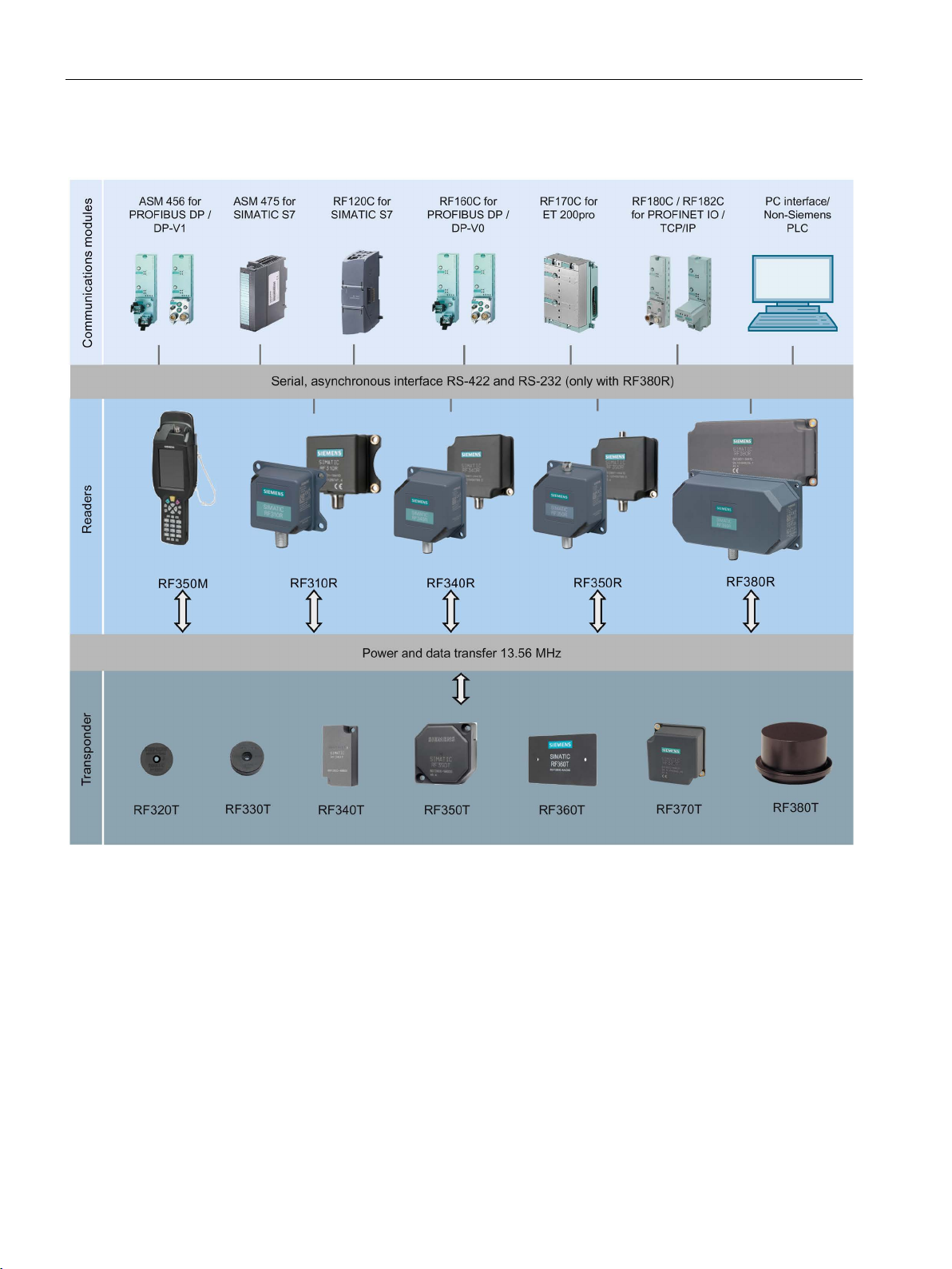
System overview
RF300 system components for high-performance applications
3.2 SIMATIC RF300
Figure 3-1 High performance system overview
SIMATIC RF300
26 System Manual, 07/2017, C79000-G8976-C345-07
Page 27

System overview
Transponder
RF310R
RF340R
RF350R
with ANT 1
RF350R
with ANT 3
RF350R
with ANT 18
RF350R
with ANT 30
RF380R
RF320T ✓ ✓ ✓ ✓ ✓ ✓
✓
RF330T
RF340T ✓ ✓ ✓ ✓ ✓ ✓
✓
RF350T ✓ ✓ ✓ --
-- ✓ ✓
RF360T ✓ ✓ ✓ --
-- ✓ ✓
RF370T
✓ 1) ✓ ✓
--
--
--
✓
RF380T
-- ✓ ✓
--
--
--
✓
1)
as of reader version "AS ≥ D"
✓
Combination possible
--
Combination not possible
Combination possible, but not recommended
3.2 SIMATIC RF300
Table 3- 4 Reader-transponder combination options for high-performance applications
✓ ✓ ✓ ✓ ✓ ✓ ✓
○
SIMATIC RF300
System Manual, 07/2017, C79000-G8976-C345-07
27
Page 28

System overview
RF300 system components for medium-performance applications
3.2 SIMATIC RF300
Figure 3-2 System overview medium-performance
SIMATIC RF300
28 System Manual, 07/2017, C79000-G8976-C345-07
Page 29

System overview
Transponder /
MDS
RF310R
(RS-422)
RF340R
RF350R
with ANT
1
RF350R
with ANT
3
RF350R
with ANT
12
RF350R
with ANT
18
RF350R
with ANT
30
RF380R
MDS D100
✓ ✓ ✓
--
--
-- ○ ✓
MDS D117
MDS D124
✓ ✓ ✓ ✓ ○ ✓ ✓
✓
MDS D126
✓ ✓ ✓
--
--
-- ✓ ✓
MDS D127
--
--
--
-- ✓ ✓
--
--
MDS D139
✓ ✓ ✓
--
--
-- ○ ✓
MDS D160
✓ ✓ ✓ ✓ ✓ ✓ ✓
✓
MDS D165
✓ ✓ ✓
--
--
-- ○ ✓
MDS D200
✓ ✓ ✓
--
--
-- ○ ✓
MDS D261
✓ ✓ ✓
--
--
-- ○ ✓
MDS D324
✓ ✓ ✓ ✓ -- ✓ ✓
✓
MDS D339 1)
✓ ✓ ✓
--
--
--
--
✓
MDS D400
✓ ✓ ✓
--
--
--
--
✓
MDS D421
--
--
--
-- ✓ ✓
--
--
MDS D422
--
--
-- ✓ -- ✓ ✓
--
MDS D423
✓ ✓ ✓ ✓ --
-- ✓ ✓
MDS D424
✓ ✓ ✓ ✓ ○ ✓ ✓
✓
MDS D425
✓ ✓ ✓ ✓ ○ ✓ ✓
✓
MDS D426
✓ ✓ ✓
--
--
-- ✓ ✓
MDS D428
✓ ✓ ✓ ✓ ✓ ✓ ✓
✓
MDS D460
MDS D521
--
--
--
-- ✓ ✓
--
--
MDS D522
--
--
--
--
-- ✓ ✓
--
MDS D524
✓ ✓ ✓
-- ○ ✓ ✓ ✓
MDS D525
✓ ✓ ✓
-- ○ ✓ ✓ ✓
MDS D526
✓ ✓ ✓
--
--
-- ✓ ✓
MDS D528
✓ ✓ ✓
-- ✓ ✓ ✓ ✓
MDS E600 2)
✓ ✓ ✓
--
--
-- ○ ✓
MDS E611 2)
✓ ✓ ✓
--
--
-- ○ ✓
MDS E623 2)
--
--
--
-- ✓ ✓
--
--
MDS E624 2)
✓ ✓ ✓
-- ○ ✓ ✓ ✓
1)
2)
Product to be discontinued; only relevant for migration projects.
✓
Combination possible
--
Combination not possible
○
Combination possible, but not recommended
3.2 SIMATIC RF300
Table 3- 5 Reader-transponder combination options for medium-performance applications
-- -- -- -- ✓ ✓ -- --
✓ ✓ ✓ ✓ ✓ ✓ ✓ ✓
as of reader version "AS ≥ D"
SIMATIC RF300
System Manual, 07/2017, C79000-G8976-C345-07
29
Page 30

System overview
Note
Note on operation of the transponders MDS D5xx and MDS E6xx
Note that the transponders MDS D5xx and MDS E6xx can only be operated in conjunction
with the readers of the
3.2 SIMATIC RF300
second generation (article number "6GT2801-xBAxx").
SIMATIC RF300
30 System Manual, 07/2017, C79000-G8976-C345-07
Page 31

System overview
RF300 system components for Scanmode applications
3.2 SIMATIC RF300
Figure 3-3 Scanmode system overview
SIMATIC RF300
System Manual, 07/2017, C79000-G8976-C345-07
31
Page 32

System overview
Transponder /
MDS
RF310R
RF380R
RF382R
MDS D100 ✓ ✓
--
MDS D124
MDS D126 ✓ ✓
--
MDS D139 ✓ ✓
--
MDS D160 ✓ ✓
✓
MDS D165 ✓ ✓
--
MDS D200 ✓ ✓
--
MDS D261 ✓ ✓
--
MDS D324 ✓ ✓
✓
MDS D339 ✓ ✓
--
MDS D400 ✓ ✓
--
MDS D423 ✓ ✓
--
MDS D424 ✓ ✓
✓
MDS D425 ✓ ✓
--
MDS D426 ✓ ✓
--
MDS D428 ✓ ✓
--
MDS D460 ✓ ✓
✓
RF320T
✓ ✓ --
RF330T
✓ ✓ --
RF340T
✓ ✓ --
RF350T
RF360T
✓ ✓ --
RF370T
-- ✓ --
RF380T
-- ✓ --
✓
Combination possible
--
Combination not possible
○
Combination possible, but not recommended
Note
Note on operation of the transponders MDS D5xx and MDS E6xx
Note that the transponders MDS D5xx and MDS E6xx can only be operated in conjunction
with the readers of the second generation (article number "6GT2801
3.2 SIMATIC RF300
Table 3- 6 Reader-transponder combination options for Scanmode applications
✓ ✓ ✓
✓ ✓ --
-xBAxx").
SIMATIC RF300
32 System Manual, 07/2017, C79000-G8976-C345-07
Page 33

System overview
3.2.3
Application areas of RF300
Main applications
Application examples
Advantages
3.2 SIMATIC RF300
SIMATIC RF300 is primarily used for non-contact identification of containers, palettes and
workpiece holders in a closed production circuit. The data carriers (transponders) remain in
the production chain and are not supplied with the products. SIMATIC RF300, with its
compact transponder and reader enclosure dimensions, is particularly suitable in confined
spaces.
● Mechanical engineering, automation systems, conveyor systems
● Ancillary assembly lines in the automotive industry, component suppliers
● Small assembly lines
● Production lines for engines, gearboxes, axles, etc.
● Assembly lines for ABS systems, airbags, brake systems, doors, cockpits, etc.
● Assembly lines for household electrical appliances, consumer electronics and electronic
communication equipment
● Assembly lines for PCs, small-power motors, contactors, switches
● Reading and writing of large data volumes within a short time results in shorter production
cycle times and helps to boost productivity
● Can be used in harsh environments thanks to rugged components with high degree of
protection
● Simple system integration into TCP/IP networks, SIMATIC S7, PROFINET and
PROFIBUS (TIA) with little effort
● Shorter commissioning times and fewer plant failures and downtimes thanks to integral
diagnostic functionalities
● Cost savings thanks to maintenance-free components
SIMATIC RF300
System Manual, 07/2017, C79000-G8976-C345-07
33
Page 34

System overview
3.3
System configuration
3.3.1
Overview
3.3.2
Assembly line example: Use of RF300 transponders
Features of the scenario
3.3 System configuration
The SIMATIC RF300 system is characterized by a high level of standardization of its
components. This means that the system follows the TIA principle throughout: Totally
Integrated Automation. It provides maximum transparency at all levels with its reduced
interface overhead. This ensures optimum interaction between all system components.
The RF300 system with its flexible components offers many possibilities for system
configuration. This chapter shows you how you can use the RF300 components on the basis
of various example scenarios.
In assembly lines, such as in engine manufacturing, many work steps are completed in
succession. Automated or manual assembly work is carried out at the individual workstations
in relatively short periods of time. The special features of the RF300 transponders, which
stand out for their large data memory and high transmission speeds, bring about many
advantages in regard to the production unit numbers of such plants.
The possibility of saving large volumes of data means savings in terms of data management
on the HOST system and considerably contributes to data security (redundant data
management e.g. HOST database or controller and data carrier)
Advantages at a glance:
● redundant data storage on the basis of large memory, availability of decentralized data
● high data rate
● data management savings on the host system
In this example scenario, engine blocks that are placed on metal pallets are conveyed on an
assembly line. The engines are assembled piece-by-piece at the individual workstations. The
RFID transponder of the type SIMATIC RF340T is mounted permanently on the underside of
the pallet. The transport speed is approx. 0.5 m/s.
In this scenario, it is an advantage that the transponder can be directly secured to metal on
the metal pallets. The small-dimensioned SIMATIC RF310R reader is integrated in the
conveyor elements in such a manner that it can communicate with the transponders from
below. Thus, it is not necessary to align the pallets or to attach several transponders.
The data of the entire production order (5000 bytes) is stored on the transponder. This data
is read at each workstation and changed or supplemented depending on the workstation,
and then written back again. Thus, the status of the engine block assembly can be
determined at any point in time, even if there is a failure at the HOST level.
Thanks to the extremely high data rate, a very short cycle time for the work steps can be
planned, which results in high end product unit numbers "engines".
SIMATIC RF300
34 System Manual, 07/2017, C79000-G8976-C345-07
Page 35

System overview
3.3 System configuration
The entire production order that is saved on the transponder can also be read manually via
the WIN-LC terminal located at each workstation. This means that virtually no additional data
management is required on the control computer.
The production order data can also be read for servicing purposes via the mobile SIMATIC
RF350M reader.
Figure 3-4 Example of engine block production
SIMATIC RF300
System Manual, 07/2017, C79000-G8976-C345-07
35
Page 36

System overview
3.3.3
Example of container and cardboard container handling: Use of ISO
transponders
Features of the scenario
3.3 System configuration
Containers of varying sizes are conveyed to picking workstations in a delivery center. There,
the individual goods are removed and packed in cartons according to the delivery note.
These cartons are marked with low-cost transponder labels and sorted to small or large
packaging workstations (according to the delivery note) by being guided or transported via
the corresponding conveyor system. The containers are marked using the MDS D100 ISO
transponder.
Advantages at a glance:
● Decision points in the conveyor system can be installed in a more favorable way
(mechanically)
● Different sizes of containers with different depths can be identified due to the range
● In contrast to bar codes, the transponders can also be written to
● Different types of transponders can be processed using one and the same reader
In this example scenario, containers of varying sizes are conveyed on a conveyor system.
Only the unique identification number (8 bytes) is read. The containers to be picked are
sorted to the corresponding workstations. The maximum transport speed is 1.0 m/s.
In this scenario, it is an advantage that the RF380R reader can read and write the
transponders at different distances on the containers without a great deal of mechanical or
control system effort due to the reading range.
During the picking process, the goods are immediately placed in different containers or
packed in cartons depending on the destination (small packaging or large packaging station).
The containers are equipped with the MDS D100 ISO transponder. The low-cost "one-way
tag" (label) is used on the cartons: it is simply glued onto the carton. Thus the goods can be
identified at any time. Again, one and the same reader hardware is used for this. The
maximum transport speed is 0.8 m/s.
In addition, flexible identification is possible at each location and at any time using the mobile
SIMATIC RF350M reader.
SIMATIC RF300
36 System Manual, 07/2017, C79000-G8976-C345-07
Page 37

System overview
3.3 System configuration
Figure 3-5 Example of container and cardboard container handling
SIMATIC RF300
System Manual, 07/2017, C79000-G8976-C345-07
37
Page 38

System overview
3.3 System configuration
SIMATIC RF300
38 System Manual, 07/2017, C79000-G8976-C345-07
Page 39

4
4.1
Fundamentals of application planning
4.1.1
Selection criteria for SIMATIC RF300 components
4.1.2
Transmission window and read/write distance
Assess your application according to the following criteria, in order to choose the right
SIMATIC RF300 components:
● Transmission distance (read/write distance)
● Tracking tolerances
● Static or dynamic data transfer
● Data volume to be transferred
● Speed in case of dynamic transfer
● Metal-free rooms for transponders and readers
● Ambient conditions such as relative humidity, temperature, chemical impacts, etc.
The reader generates an inductive alternating field. The field is strongest close to the reader;
however, a read/write distance of "zero" between reader and transponder is not
recommended.
The field strength of the alternating field decreases strongly the further away from the reader.
The distribution of the antenna field depends on the structure and geometry of the antennas
in the reader and transponder.
For the transponder to function correctly, a minimum field strength at the transponder must
be achieved at a distance S
The figures below show the transmission window between transponder and reader or
between transponder and antenna:
from the reader or the antenna.
g
SIMATIC RF300
System Manual, 07/2017, C79000-G8976-C345-07
39
Page 40

Planning the RF300 system
Sa
Operating distance between transponder and reader
sponder, at which the transmission can still just function under normal conditions)
Ly with RF380R and RF382R)
Ly with RF380R and RF382R)
M
Field centerpoint
SP
Intersection of the axes of symmetry of the transponder
4.1 Fundamentals of application planning
Sg Limit distance (maximum clear distance between upper surface of the reader and the tran-
Lx Length of a transmission window in the x direction while maintaining the working distance (Lx ≠
Ly Length of a transmission window in the y direction while maintaining the working distance (Lx ≠
Figure 4-1 Transmission window and read/write distance reader
SIMATIC RF300
40 System Manual, 07/2017, C79000-G8976-C345-07
Page 41

Planning the RF300 system
Note
Transmission window with RF380R and RF382R
Note that the transmission window of the reader RF380R is not square (L
as
large a transmission window as possible, make sure that the transponder only crosses the
reader in the x direction.
Sa
Operating distance between transponder and reader
sponder, at which the transmission can still just function under normal conditions)
Ld
Diameter of a transmission window
SP
Intersection of the axes of symmetry of the transponder
4.1 Fundamentals of application planning
≠ Ly). To obtain
x
Sg Limit distance (maximum clear distance between upper surface of the reader and the tran-
Figure 4-2 Transmission window and read/write distance round antenna
SIMATIC RF300
System Manual, 07/2017, C79000-G8976-C345-07
41
Page 42

Planning the RF300 system
Aids for calculating the field data
Note
Determining the operating distance, limit distance and transmission window
Remember that you can obtain
field data acquisition. You will find this on the DVD "Ident Systems, Software &
Documentation".
4.1.3
Width of the transmission window
Determining the width of the transmission window
B:
Width of the transmission window
L:
Length of the transmission window
Tracking tolerances
4.1 Fundamentals of application planning
The transponder can be used as soon as the intersection (SP) of the transponder enters the
area of the transmission window.
From the diagrams above, it can also be seen that operation is possible within the area
between S
shrinks to a single point at distance S
between S
and Sg. The active operating area reduces as the distance increases, and
a
. Only static mode should thus be used in the area
g
and Sg.
a
the values Sa, Sg and L simply and quickly using the tool for
The following approximation formula can be used for practical applications:
The width of the transmission window (B) is particularly important for the mechanical tracking
tolerance. The formula for the dwell time is valid without restriction when B is observed.
SIMATIC RF300
42 System Manual, 07/2017, C79000-G8976-C345-07
Page 43

Planning the RF300 system
4.1.4
Impact of secondary fields
①
Main field
②
Secondary field
4.1 Fundamentals of application planning
Secondary fields in the range from 0 mm to 30% of the limit distance (Sg) generally always
exist.
They should, however, only be used during configuration in exceptional cases, since the
read/write distances are very limited. Exact details of the secondary field geometry cannot be
given, since these values depend heavily on the operating distance and the application.
When working in dynamic mode, remember that during the transition from the secondary
field to the main field the presence of the tag is lost temporarily. It is therefore advisable to
select a distance > 30 % of S
.
g
Figure 4-3 Gap in the field resulting from secondary fields
SIMATIC RF300
System Manual, 07/2017, C79000-G8976-C345-07
43
Page 44

Planning the RF300 system
Secondary fields without shielding
①
Main field
②
Secondary field
4.1 Fundamentals of application planning
The following graphic shows typical primary and secondary fields, if no shielding measures
are taken.
Figure 4-4 Secondary field without shielding
In this arrangement, the reader can also read tags via the secondary field. Shielding is
required in order to prevent unwanted reading via the secondary field, as shown and
described in the following.
SIMATIC RF300
44 System Manual, 07/2017, C79000-G8976-C345-07
Page 45

Planning the RF300 system
Secondary fields with shielding
①
Main field
②
Secondary field
4.1 Fundamentals of application planning
The following graphic shows typical primary and secondary fields, with metal shielding this
time.
The metal shielding prevents the reader from detecting tags via the secondary field.
Figure 4-5 Secondary field with shielding
SIMATIC RF300
System Manual, 07/2017, C79000-G8976-C345-07
45
Page 46

Planning the RF300 system
4.1.5
Setup help of the readers of the second generation
Meaning of the LED operating display in the "Setup" mode
LED
Meaning
The reader is turned off.
nently.
4.1 Fundamentals of application planning
After turning on the reader (connection to the power supply) and the following startup phase,
the reader automatically changes to the "Setup" mode. During this the antenna (readerinternal or external) is turned on, in contrast to generation 1 in which the antenna is turned
on by a RESET.
In this status "search for transponders" the reader scans the antenna field for transponders
with all air interface protocols (RF300, ISO 15693, ISO 14443). If a transponder is
recognized in the antenna field of the reader only the HF protocol of the recognized
transponder type is used and there is a change in the status to "Show quality". In this status
you obtain direct feedback about the quality of the communication with the transponder via
the LED. Depending on the environment (metal, interference) or the field coupling with the
transponder (size of the transponder antenna) as well as the individual field geometry (shape
of the main and side lobe) of the reader, communication can be very good (permanent light)
or good (flickering) at certain locations in the antenna field. These factors give users the
option of finding the optimal area in the specific installation situation or in a combination. If no
transponder is recognized for a longer period of time, the reader changes back to the
"Search for transponders" status.
When a "RESET" command is received, the reader changes back to the normal operation as
known from the RF300.
The operational statuses of the reader are displayed by two LEDs. The LEDs can adopt the
colors white green, red, yellow or blue and the statuses off
Table 4- 1 Display elements
/ There is transponder in the antenna field.
The reader is turned on and is searching for transponders.
The reader is in the "Setup" mode, in the "Search for transponders" status and
has not yet received a "RESET" command and is not ready.
The reader is in the "Setup" mode, in the status "Show quality", has not yet received a "RESET" command and is not ready.
Depending on the quality of the communication, the LED flickers or is lit perma-
, on , flashing .
SIMATIC RF300
46 System Manual, 07/2017, C79000-G8976-C345-07
Page 47

Planning the RF300 system
4.1.6
Permissible directions of motion of the transponder
Detection area and direction of motion of the transponder
4.1.7
Operation in static and dynamic mode
Operation in static mode
4.1 Fundamentals of application planning
The transponder and reader have no polarization axis, i.e. the transponder can come in from
any direction, assume any position as parallel as possible to the reader, and cross the
transmission window. The figure below shows the active area for various directions of
transponder motion:
Figure 4-6 Detection areas of the reader for different directions of transponder motion
If working in static mode, the transponder can be operated up to the limit distance (Sg). The
transponder must then be positioned exactly over the reader:
Transmission window
Direction of motion of the transponder
Detection area L x W
Figure 4-7 Operation in static mode
SIMATIC RF300
System Manual, 07/2017, C79000-G8976-C345-07
47
Page 48

Planning the RF300 system
Operation in dynamic mode
4.1 Fundamentals of application planning
When working in dynamic mode, the transponder moves past the reader. The transponder
can be used as soon as the intersection (SP) of the transponder enters the circle of the
transmission window. In dynamic mode, the operating distance (S
[Operating distances, see Chapter Field data for transponders, readers and antennas
(Page 51)]
) is of primary importance.
a
Figure 4-8 Operation in dynamic mode
SIMATIC RF300
48 System Manual, 07/2017, C79000-G8976-C345-07
Page 49

Planning the RF300 system
4.1.8
Dwell time of the transponder
tV:
Dwell time of the transponder
L:
Length of the transmission window
v
:
Speed of the transponder (tag) in dynamic mode
0.8: Constant factor used to compensate for temperature influence
ances
tV::
Dwell time of the data memory in the field of the reader
tK:
Communication time between transponder and communication module
tK:
Communication time between transponder and communication module
K Constant; the constant is an internal system time. This includes the time for power
buildup on the MDS and for command transfer
t
Byte
Transmission time for 1 byte
n
Amount of user data in bytes
n
Maximum amount of user data in bytes in dynamic mode
tV
Dwell time of the data memory in the field of the reader
4.1 Fundamentals of application planning
The dwell time is the time in which the transponder remains within the transmission window
of the reader. The reader can exchange data with the transponder during this time.
The dwell time is calculated as follows:
Tag
and production toler-
The dwell time can be of any duration in static mode. The dwell time must be sufficiently long
to allow communication with the transponder.
The dwell time is defined by the system environment in dynamic mode. The volume of data
to be transferred must be matched to the dwell time or vice versa. As a general rule:
or Calculation of the maximum amount of user data
max
SIMATIC RF300
System Manual, 07/2017, C79000-G8976-C345-07
49
Page 50

Planning the RF300 system
4.1.9
Communication between communications module, reader and transponder
Aids for calculating the data transmission times
4.1 Fundamentals of application planning
User-friendly calculation tools are available for the communications modules ASM 456,
RF160C, RF170C and RF180C to calculate data transfer times. The calculation tools can be
found on the DVD "Ident Systems Software & Documentation", article number 6GT20802AA20.
Figure 4-9 User interface of the calculation tool for command processing time
SIMATIC RF300
50 System Manual, 07/2017, C79000-G8976-C345-07
Page 51

Planning the RF300 system
Aids for calculating the field data
4.2
Field data for transponders, readers and antennas
Tolerances of ±20 % are permitted due to production or temperature
conditions.
Note
Transmission gaps
If the minimum operating distance (S
center of the field. Communication with the transponder is not possible in the transmission
gap, see section "
4.2 Field data for transponders, readers and antennas
You will also find a tool for calculating field data on the DVD "Ident Systems, Software &
Documentation". Using this tool, among other things you can calculate the operating
distance (S
), limit distance (Sg) and transmission window (L).
a
Figure 4-10 User interface of the calculation tool for field data acquisition
The following tables show the field data for all SIMATIC RF300 components of transponders
and readers. This makes the correct selection of a transponder and reader particularly easy.
All the technical specifications listed are typical data and are applicable for an ambient
temperature between 0 °C and +50 °C, a supply voltage between 22 and 27 VDC and a
metal-free environment.
If the entire voltage range at the reader of 20 VDC to 30 VDC and/or the entire temperature
range of transponders and readers is used, the field data is subject to further tolerances.
) is not observed, a transmission gap can occur in the
a
Impact of secondary fields (Page 43)".
SIMATIC RF300
System Manual, 07/2017, C79000-G8976-C345-07
51
Page 52

Planning the RF300 system
Note
Possible reader-transponder combinations
The tables of the following section show the possible reader
4.2.1
Field data of RF300 transponders
Length of the transmission
window (L)
Operating distance (Sa)
Limit distance (Sg)
RF320T
30
1...23
26
RF330T
30
2...18
21
RF340T
RF350T
45
2...47
53
RF360T
45
2...60
68
RF370T
70
2...45
60
All values are in mm
The values relate to the RF310R reader as of version "D".
Length of the transmission
window (L)
Operating distance (Sa)
Limit distance (Sg)
RF320T
45
1...20
25
RF330T
40
2...18
23
RF340T
80
2...50
58
RF350T
80
2...60
75
RF360T
90
2...65
85
RF370T
85
5...60
80
RF380T
90
5...80
100
All values are in mm
4.2 Field data for transponders, readers and antennas
-transponder combinations.
The limit distances (Sg) and operating distances (Sa) along with the length of the
transmission window for each reader-transponder combination are listed in the tables below.
In dynamic mode, make sure that rectangular transponders cross the antenna field in the
longitudinal direction.
Table 4- 2 Field data RF310R reader
40 2...36 41
Table 4- 3 Field data RF340R reader
SIMATIC RF300
52 System Manual, 07/2017, C79000-G8976-C345-07
Page 53

Planning the RF300 system
Length of the transmission
window (L)
Operating distance (Sa)
Limit distance (Sg)
RF320T
45
1...30
37
RF330T
RF340T
80
2...55
70
RF350T
80
2...65
85
RF360T
90
2...75
100
RF370T
85
5...65
85
RF380T
90
5...90
110
All values are in mm
Length of the transmission
window (L)
Operating distance (Sa)
Limit distance (Sg)
RF320T
25
1...15
18
RF330T
25
1...10
15
RF340T
40
2...25
30
All values are in mm
Diameter of the transmis-
sion window (Ld)
Operating distance (Sa)
Limit distance (Sg)
RF320T
10
0...10
13
RF330T
10
0...11
13
RF340T
20
0...18
22
All values are in mm
Diameter of the transmis-
sion window (Ld)
Operating distance (Sa)
Limit distance (Sg)
RF320T
15
0...15
20
RF330T
22
0...15
18
RF340T
35
0...25
30
RF350T
35
0...35
40
RF360T
All values are in mm
4.2 Field data for transponders, readers and antennas
Table 4- 4 Field data RF350R reader / ANT 1
40 1...25 30
Table 4- 5 Field data RF350R reader / ANT 3
Table 4- 6 Field data RF350R reader / ANT 18
Table 4- 7 Field data RF350R reader / ANT 30
80 2...32 38
SIMATIC RF300
System Manual, 07/2017, C79000-G8976-C345-07
53
Page 54

Planning the RF300 system
Length of the transmission window
Operating distance
(Sa)
Limit distance (Sg)
in the x direction (Lx)
in the y direction (Ly)
RF320T
100
40
2...45
60
RF330T
120
30
5...45
52
RF340T
RF350T
140
60
2...100
125
RF360T
160
70
2...120
150
RF370T
160
65
5...100
135
RF380T
180
75
5...125
160
All values are in mm
RF380R reader: Setting the transmit power
Value
Transmit power
02
0.5 W
03
0.75 W
04
1.0 W
05
1.25 W (default)
06
1.5 W
07
1.75 W
08
2.0 W
4.2 Field data for transponders, readers and antennas
Table 4- 8 Field data RF380R reader
120 50 2...80 105
The RF380R reader (6GT2801-3AB10) allows the transmission output power to be set with
the aid of the "distance_limiting" input parameter (you will find more detailed information in
the document "Input parameters for the RF300 system for programming via communications
modules"). For this, values from 0.5 W to 2.0 W can be set in 0.25 W increments. When
doing this, remember that the change to the transmit power will affect the detection in the
limit range (upper/ lower operating distance), as well as the minimum distance that is to be
maintained between adjacent RF380Rs. A higher working version is not to be expected.
Table 4- 9 Adjustable transmit power of the RF380R reader with the aid of the "distance_limiting"
parameter
SIMATIC RF300
54 System Manual, 07/2017, C79000-G8976-C345-07
Page 55

Planning the RF300 system
Note
Setting outside the range
Settings outside the specified range (02 ... 08) have the effect that the default value (1.25 W)
is set. In this case for reasons of compatibility there is no error message.
This setting is not necessary with the RF380R readers of the 2nd generation (6GT
3BAx0) because the power limits are optimized automatically depending on the reader
transponder distance. For reasons of compatibility this setting can nevertheless be made.
Note that the values "02", "03" and "04" bring about a reduction of the power
approximately 50%.
You will find more information on this subject in the chapter "
)"
section "Minimum distance from
See also
4.2 Field data for transponders, readers and antennas
2801-
-
of
Minimum clearances (Page 64
reader to reader".
Product Information "Input parameters for the RF300 system for programming via
communications modules" (https://support.industry.siemens.com/cs/ww/en/ps/15033/man
)
SIMATIC RF300
System Manual, 07/2017, C79000-G8976-C345-07
55
Page 56

Planning the RF300 system
4.2.2
Field data of ISO transponders (MDS D)
Length of the transmission
window (L)
Operating distance (Sa)
Limit distance (Sg)
MDS D100
40
2...93
105
MDS D124
MDS D126
90
2...65
73
MDS D139
MDS D160
30
2...39
44
MDS D165
130
2...90
102
MDS D200
120
2...80
90
MDS D261
80
2...74
83
MDS D324
30
2...47
63
MDS D339
85
5...74
84
MDS D400
90
2...104
115
MDS D423
55
2...35
40
MDS D424
35
1...68
75
MDS D425
30
1...22
25
MDS D426
90
5...75
90
MDS D428
30
1...40
45
MDS D460
30
1...32
38
MDS D524
35
1...70
78
MDS D525
30
1...22
25
MDS D526
90
5...80
90
MDS D528
All values are in mm
4.2 Field data for transponders, readers and antennas
The limit distances (Sg) and operating distances (Sa) along with the length of the
transmission window for each reader-transponder combination are listed in the tables below.
Observe the following information for field data of ISO transponders:
● A maximum median deviation of ±2 mm is permitted in static mode (without affecting the
field data).
● In dynamic mode, make sure that rectangular transponders cross the antenna field in the
longitudinal direction.
Table 4- 10 Field data RF310R reader
30 2...64 72
105 5...96 109
SIMATIC RF300
56 System Manual, 07/2017, C79000-G8976-C345-07
30 1...43 48
Page 57

Planning the RF300 system
Length of the transmission
window (L)
Operating distance (Sa)
Limit distance (Sg)
MDS D100
90
5...110
140
MDS D124
MDS D126
80
2...85
110
MDS D139
90
5...80
110
MDS D160
50
2...35
60
MDS D165
130
15...120
140
MDS D200
125
10...100
115
MDS D261
95
15...60
70
MDS D324
50
2...55
70
MDS D339
100
5...75
85
MDS D400
140
2...100
130
MDS D423
65
5...40
48
MDS D424
50
2...55
70
MDS D425
45
2...20
30
MDS D426
110
0...80
100
MDS D428
45
2...40
50
MDS D460
45
2...25
40
MDS D524
50
2...55
70
MDS D525
45
2...20
30
MDS D526
110
0...80
100
MDS D528
1)
2)
All values are in mm
4.2 Field data for transponders, readers and antennas
Table 4- 11 Field data RF340R reader
60 2...60 75
1)
2)
45 2...40 50
When operating the reader of the second generation and an ambient temperature > 50 °C, the
operating distance (S
) is 15 ... 80 mm.
a
When operating the reader of the second generation the operating distance (Sa) is 40 ... 100 mm
and the limit distance .(S
) is 150 mm.
g
SIMATIC RF300
System Manual, 07/2017, C79000-G8976-C345-07
57
Page 58

Planning the RF300 system
Length of the transmission
window (L)
Operating distance (Sa)
Limit distance (Sg)
MDS D100
80
5...110
140
MDS D124
MDS D126
150
2...90
120
MDS D139
75
5...85
115
MDS D160
50
2...35
60
MDS D165
140
5...100
120
MDS D200
130
5...95
115
MDS D261
100
5...80
95
MDS D324
50
2...66
78
MDS D339
110
5...90
105
MDS D400
140
2...110
135
MDS D423
85
10...40
50
MDS D424
50
2...75
88
MDS D425
40
2...25
35
MDS D426
110
2...85
95
MDS D428
40
2...40
50
MDS D460
40
2...32
38
MDS D524
50
2...65
85
MDS D525
40
2...25
35
MDS D526
110
2...85
105
MDS D528
All values are in mm
Diameter of the transmis-
sion window (Ld)
Operating distance (Sa)
Limit distance (Sg)
MDS D124
40
1...35
42
MDS D160
40
1...28
35
MDS D324
MDS D422
20
1...11
18
MDS D423
30
5...20
30
MDS D424
40
1...40
48
MDS D425
25
2...18
22
MDS D428
30
2...28
30
MDS D460
30
1...20
28
All values are in mm
4.2 Field data for transponders, readers and antennas
Table 4- 12 Field data RF350R reader / ANT 1
55 2...65 85
40 2...35 50
Table 4- 13 Field data RF350R reader / ANT 3
40 1...22 32
SIMATIC RF300
58 System Manual, 07/2017, C79000-G8976-C345-07
Page 59

Planning the RF300 system
Diameter of the transmis-
sion window (Ld)
Operating distance (Sa)
Limit distance (Sg)
MDS D117 2 0...2
3
MDS D127
MDS D160
15
0...8
12
MDS D421 6 0...3
5
MDS D428
15
1...10
17
MDS D460 8 1...8
10
MDS D521 6 0...3
5
MDS D528
15
1...10
17
All values are in mm
Diameter of the transmis-
sion window (Ld)
Operating distance (Sa)
Limit distance (Sg)
MDS D117 3 0...5
6
MDS D124
27
2...24
28
MDS D127 3 0...5
6
MDS D160
20
1...18
20
MDS D324
25
1...22
28
MDS D421
10
0...6
8
MDS D422
20
1...10
13
MDS D424
25
1...27
35
MDS D425
17
1...10
14
MDS D428
17
1...15
20
MDS D460
15
1...12
16
MDS D521
10
0...6
8
MDS D522
20
1...10
13
MDS D524
25
1...27
35
MDS D525
17
1...10
14
MDS D528
All values are in mm
4.2 Field data for transponders, readers and antennas
Table 4- 14 Field data RF350R reader / ANT 12
2 0...3 4
Table 4- 15 Field data RF350R reader / ANT 18
SIMATIC RF300
System Manual, 07/2017, C79000-G8976-C345-07
17 1...15 20
59
Page 60

Planning the RF300 system
Diameter of the transmis-
sion window (Ld)
Operating distance (Sa)
Limit distance (Sg)
MDS D124
30
1...35
40
MDS D126
MDS D160
25
1...24
28
MDS D324
30
1...35
40
MDS D422
30
0...14
16
MDS D423
45
5...22
28
MDS D424
28
0...45
50
MDS D425
25
1...15
20
MDS D426
65
0...45
48
MDS D428
25
1...25
28
MDS D460
22
1...18
20
MDS D522
30
0...15
19
MDS D524
28
0...45
50
MDS D525
25
1...15
20
MDS D526
65
0...45
48
MDS D528
25
1...25
28
All values are in mm
Length of the transmission window
Operating distance
(Sa)
Limit distance (Sg)
in the x direction (Lx)
in the y direction (Ly)
MDS
D1001)
MDS D124
80
80
1...120
140
MDS D126
180
140
2...145
190
MDS D139
140
90
5...160
200
MDS D160
80
40
2...64
80
MDS D165
MDS
D2002)
MDS
D2613)
MDS D324
100
60
2...96
120
MDS D339
290
140
5...160
180
MDS D400
240
120
10...200
240
MDS D423
110
60
5...75
90
MDS D424
100
70
2...120
140
MDS D425
80
45
2...35
50
4.2 Field data for transponders, readers and antennas
Table 4- 16 Field data RF350R reader / ANT 30
70 0...42 50
Table 4- 17 Field data RF380R reader
140 100 10...170 210
200 140 10...170 200
1)
200 160 20...150 195
190 120 20..120 160
SIMATIC RF300
60 System Manual, 07/2017, C79000-G8976-C345-07
Page 61

Planning the RF300 system
Length of the transmission window
Operating distance
(Sa)
Limit distance (Sg)
in the x direction (Lx)
in the y direction (Ly)
MDS D426
220
160
0...155
195
MDS D428
80
50
2…70
95
MDS D460
MDS D524
100
70
2...120
140
MDS D525
80
45
2...35
50
MDS D526
220
160
0...155
195
MDS D528
80
50
2…70
95
All values are in mm
1)
2)
3)
tion) or 14 mm (2nd generation) with ambient temperatures of 50 °C and higher.
Length of the transmission window
Operating distance
(Sa)
Limit distance (Sg)
in the x direction (Lx)
in the y direction
(Ly)
MDS D124
70
130
40...65
75
MDS D160
50
100
35...50
65
MDS D324
60
120
40...65
75
MDS D424
65
120
40...65
75
MDS D460
40
80
30...50
60
All values are in mm
4.2.3
Field data of ISO transponders (MDS E)
4.2 Field data for transponders, readers and antennas
80 70 2…65 90
Keep in mind that the minimum distance must be increased by 10 mm with ambient temperatures
of 40 °C and higher.
Keep in mind that the minimum distance of the reader to the transponder must be increased by
7 mm (1st generation) or 6 mm (2nd generation) for every 5 °C rise in temperature with ambient
temperatures of 25 °C and higher. The minimum distance must be increased by 15 mm with ambient temperatures of 50 °C and higher (1st and 2nd generation).
Keep in mind that the minimum distance of the reader to the transponder must be increased by
5 mm (1st generation) or 3 mm (2nd generation) for every 5 °C rise in temperature with ambient
temperatures of 25 °C and higher. The minimum distance must be increased by 9 mm (1st genera-
Table 4- 18 Field data RF382R reader
The limit distances (Sg) and operating distances (Sa) along with the length of the
transmission window for each reader-transponder combination are listed in the tables below.
Observe the following information for field data of ISO transponders:
● A maximum median deviation of ±2 mm is possible in static mode (without affecting the
field data).
SIMATIC RF300
System Manual, 07/2017, C79000-G8976-C345-07
longitudinal direction.
● In dynamic mode, make sure that rectangular transponders cross the antenna field in the
61
Page 62

Planning the RF300 system
Note
Relenace of the MDS E transponders
The MDS E transponders are products that will be discontinued. These are relevant for
migration proje
generation 2.
Note that the MDS E transponders can only be operated in conjunction with the readers of
the second generation!
Length of the transmission
window (L)
Operating distance (Sa)
Limit distance (Sg)
MDS E600
80
2...30
43
MDS E611
80
2...40
60
MDS E624
45
2...25
36
All values are in mm
Length of the transmission
window (L)
Operating distance (Sa)
Limit distance (Sg)
MDS E600
90
5...50
65
MDS E611
90
10...50
65
MDS E624
60
2...35
45
All values are in mm
Length of the transmission
window (L)
Operating distance (Sa)
Limit distance (Sg)
MDS E600
70
10...50
60
MDS E611
100
10...50
65
MDS E624
55
2...35
45
All values are in mm
4.2 Field data for transponders, readers and antennas
cts in which existing RFID systems are replaced by SIMATIC RF300,
Table 4- 19 Field data RF310R reader
Table 4- 20 Field data RF340R reader
Table 4- 21 Field data RF350R reader / ANT 1
SIMATIC RF300
62 System Manual, 07/2017, C79000-G8976-C345-07
Page 63

Planning the RF300 system
Diameter of the transmis-
sion window (Ld)
Operating distance (Sa)
Limit distance (Sg)
MDS E623 6 0...3
5
All values are in mm
Diameter of the transmis-
sion window (Ld)
Operating distance (Sa)
Limit distance (Sg)
MDS E623
10
0...6
8
MDS E624
25
2...15
20
All values are in mm
Diameter of the transmis-
sion window (Ld)
Operating distance (Sa)
Limit distance (Sg)
MDS E624
28
1...20
24
All values are in mm
Length of the transmission
window (L
x/y
)
Operating distance (Sa)
Limit distance (Sg)
MDS E600
100/70
10...80
95
MDS E611
110/100
10...115
135
MDS E624
90/50
5...50
60
All values are in mm
4.2 Field data for transponders, readers and antennas
Table 4- 22 Field data RF350R reader / ANT 12
Table 4- 23 Field data RF350R reader / ANT 18
Table 4- 24 Field data RF350R reader / ANT 30
Table 4- 25 Field data RF380R reader
SIMATIC RF300
System Manual, 07/2017, C79000-G8976-C345-07
63
Page 64

Planning the RF300 system
4.2.4
Minimum clearances
Minimum distance from transponder to transponder
RF310R
RF340R
RF350R /
ANT 1
RF350R /
ANT 3
RF350R /
ANT 18
RF350R /
ANT 30
RF380R
RF320T
≥ 50
≥ 70
≥ 70
40
≥ 20
≥ 40
≥ 120
RF330T
RF340T
≥ 60
≥ 80
≥ 80
60
≥ 40
≥ 40
≥ 140
RF350T
≥ 60
≥ 80
≥ 80
70
--
≥ 50
≥ 150
RF360T
≥ 60
≥ 80
≥ 80
--
--
50
≥ 120
RF370T
--
≥ 80
≥ 80
--
--
--
≥ 130
RF380T
--
≥ 80
≥ 80
--
--
--
≥ 150
All values are in mm, relative to the operating distance (S
edge and transponder edge
RF310R
RF340R
RF350R /
ANT 1
RF350R /
ANT 3
RF350R /
ANT 12
RF350R /
ANT 18
RF350R /
ANT 30
RF380R
RF382R
1)
MDS D100
≥ 120
≥ 240
≥ 240
--
--
--
--
≥ 420
--
MDS D117
--
--
--
--
≥ 20
≥ 30
--
--
--
MDS D124
150
MDS D126
≥ 120
≥ 140
≥ 140
--
--
--
≥ 100
≥ 400
--
MDS D127
--
--
--
--
≥ 25
≥ 30
--
--
--
MDS D139
≥ 200
≥ 200
≥ 200
--
--
--
≥ 80
≥ 450
--
MDS D160
120
MDS D165
≥ 120
≥ 140
≥ 140
--
--
--
--
≥ 500
--
MDS D200
≥ 120
≥ 150
≥ 150
--
--
--
--
≥ 500
--
MDS D261
≥ 160
≥ 200
≥ 200
--
--
--
--
≥ 400
--
MDS D324
150
MDS D339
≥ 200
≥ 140
≥ 140
--
--
--
--
≥ 450
--
MDS D400
≥ 220
≥ 240
≥ 240
--
--
--
--
≥ 500
--
MDS D421
--
--
--
--
≥ 15
≥ 15
--
--
--
MDS D422
MDS D423
≥ 100
≥ 120
≥ 120
≥ 60
--
≥ 40
≥ 60
≥ 250
--
4.2 Field data for transponders, readers and antennas
The specified distances refer to a metal-free environment. For a metallic environment, the
specified minimum distances must be multiplied by a factor of 1.5. The transponders
designed specifically for installation in/on metal are an exception to this.
Table 4- 26 Minimum distances RF300 transponder
≥ 40 ≥ 50 ≥ 50 60 ≥ 20 ≥ 30 ≥ 120
Table 4- 27 Minimum distances ISO transponder
≥ 100 ≥ 180 ≥ 180 90 -- ≥ 50 ≥ 80 ≥ 360 ≥ 100,
≥ 120 ≥ 150 ≥ 150 ≥ 60 ≥ 30 ≥ 50 ≥ 60 ≥ 300 ≥ 100,
≥ 120 ≥ 180 ≥ 180 ≥ 85 -- ≥ 50 ≥ 80 ≥ 360 ≥ 100,
) between reader and transponder, and between transponder
a
-- -- -- ≥ 60 -- ≥ 30 ≥ 40 -- --
SIMATIC RF300
64 System Manual, 07/2017, C79000-G8976-C345-07
Page 65

Planning the RF300 system
RF310R
RF340R
RF350R /
ANT 1
RF350R /
ANT 3
RF350R /
ANT 12
RF350R /
ANT 18
RF350R /
ANT 30
RF380R
RF382R
1)
MDS D424
180
MDS D425
≥ 70
≥ 100
≥ 100
≥ 60
--
--
≥ 60
≥ 250
--
MDS D426
≥ 120
≥ 120
≥ 140
--
--
≥ 30
≥ 60
≥ 400
--
MDS D428
MDS D460
120
MDS D521
--
--
--
--
≥ 15
≥ 15
--
--
--
MDS D522
--
--
--
--
--
≥ 30
≥ 40
--
--
MDS D524
180
MDS D525
≥ 70
≥ 100
≥ 100
≥ 60
--
--
≥ 60
≥ 250
--
MDS D526
≥ 120
≥ 120
≥ 140
--
--
≥ 30
≥ 60
≥ 400
--
MDS D528
≥ 100
≥ 150
≥ 150
--
≥ 30
≥ 50
≥ 60
≥ 300
--
MDS E600
MDS E611
MDS E623
MDS E624
1)
2)
All values are in mm, relative to the operating distance (S
edge and transponder edge
Minimum distance from reader to reader
RF310R to
RF310R
RF340R to
RF340R1)
RF380R to
RF380R2)
RF382R to
RF382R
readers
All values are in mm
4.2 Field data for transponders, readers and antennas
≥ 100 180 ≥ 180 ≥ 80 -- ≥ 50 ≥ 80 ≥ 360 ≥ 100,
≥ 100 ≥ 150 ≥ 150 ≥ 60 ≥ 30 ≥ 50 ≥ 60 ≥ 300 - ≥ 100 ≥ 150 ≥ 150 ≥ 60 ≥ 30 ≥ 50 ≥ 60 ≥ 300 ≥ 100,
≥ 100 180 ≥ 180 -- -- ≥ 50 ≥ 80 ≥ 360 ≥ 100,
2)
≥ 120 ≥ 240 ≥ 240 -- -- -- -- 500 --
≥ 120 ≥ 240 ≥ 240 -- -- -- -- 420 --
2)
-- -- -- -- ≥ 15 ≥ 15 -- -- --
2)
≥ 100 180 ≥ 180 ≥ 80 -- ≥ 50 ≥ 80 360 --
2)
The first value is the minimum distance of the transponders in the horizontal field, the second value is the minimum
distance of the transponders in the vertical field.
Product being discontinued; only relevant for migration projects with the readers of the second generation.
) between reader and transponder, and between transponder
a
Table 4- 28 Minimum distances reader
with 2 readers ≥ 150 ≥ 200 / 350 ≥ 400 ≥ 200
with several
≥ 200 ≥ 250 / 500 ≥ 500 ≥ 200
1)
The value on the left refers to the first generation; the value on the right refers to the
second generation of the RF340R.
SIMATIC RF300
System Manual, 07/2017, C79000-G8976-C345-07
65
Page 66

Planning the RF300 system
"distance_limiting"
value
(hexadecimal)
Transmit power
Factor
02; 03
0.5 - 0.75 W
0.8
07; 08
1.75 - 2.0 W
1.2
Minimum distance from antenna to antenna
ANT 1
ANT 3
ANT 3S
ANT 8
ANT 12
ANT 18
ANT 30
All values are in mm
Note
Effect on inductive fields by not maintaining the minimum distances of the readers
If the values fall below the values specified in the "Minimum distance readers" and "Minimum
distances antennas" tables , there is a risk of the function being affected by
In this case, the data transfer time would increase unpredictably or a command would be
aborted with an error.
Keeping to the values specified in the "Minimum distance readers" and "Minimum distances
antennas" tables is therefore essent
Note
Please also observe the graphic representations of the minimum distances in the respective
chapters on readers.
4.2 Field data for transponders, readers and antennas
2)
The permissible minimum distance between two RF380Rs depends on the transmit power
that is set. The specified minimum distance must be multiplied by the following factor,
depending on the output:
Table 4- 29 Effect on the minimum distance of the transmit power with RF380R
04; 05; 06 1.0 - 1.5 W 1.0
Table 4- 30 Minimum distances antennas
≥ 300 ≥ 150 ≥ 20 ≥ 50 ≥ 70 ≥ 100 ≥ 100
You will find detailed information on the minimum distances between antennas the section
"Minimum distance between antennas (Page 228)".
inductive fields.
ial.
If the specified minimum distance cannot be complied with due to the physical configuration,
the SET-ANT command can be used to activate and deactivate the RF field of the reader.
The application software must be used to ensure that only one reader is active (antenna is
switched on) at a time.
SIMATIC RF300
66 System Manual, 07/2017, C79000-G8976-C345-07
Page 67

Planning the RF300 system
4.3
Installation guidelines
4.3.1
Overview
4.3.2
Reduction of interference due to metal
Representation
Description
Problem:
Remedy:
4.3 Installation guidelines
The transponder and reader complete with their antennas are inductive devices. Any type of
metal in the vicinity of these devices affects their functionality. Some points need to be
considered during planning and installation if the values described in the "Field data
(Page 51)" section are to retain their validity:
● Minimum spacing between two readers or their antennas
● Minimum distance between two adjacent data memories
● Metal-free area for flush-mounting of readers or their antennas and transponders in metal
● Mounting of multiple readers or their antennas on metal frames or racks
The following sections describe the impact on the operation of the RFID system when
mounted in the vicinity of metal.
Table 4- 31 Interference due to metal rack
A metal rack is located above the
transmission window of the reader.
This affects the entire field. In particular, the transmission window
between reader and transponder is
reduced.
The transmission window is no
longer affected if the transponder is
mounted differently.
SIMATIC RF300
System Manual, 07/2017, C79000-G8976-C345-07
67
Page 68

Planning the RF300 system
Representation
Description
Problem:
Remedy:
Remedy:
Mounting of several readers on metal frames or racks
4.3 Installation guidelines
Table 4- 32 Flush-mounting of transponders and readers
Flush-mounting of transponders and
readers is possible in principle.
However, the size of the transmission window is significantly reduced.
The following measures can be
used to counteract the reduction of
the window:
Enlargement of the non-metallic
spacer below the transponder
and/or reader.
The transponder and/or reader are
10 to 20 mm higher than the metal
surround.
(The value x ≥ 100 mm is valid, e.g.
for RF310R. It indicates that, for a
distance x ≥ 100 mm, the reader
can no longer be significantly affected by metal.)
Increase the distances a, b to metal.
The following rule of thumb can be
used:
• Increase a, b by a factor of 2 to 3
over the values specified for
metal-free areas
• Increasing a, b has a greater
effect for readers or transponders with a large limit distance
than for readers or transponders
with a small limit distance.
SIMATIC RF300
68 System Manual, 07/2017, C79000-G8976-C345-07
Any reader mounted on metal couples part of the field to the metal frame. There is normally
no interaction as long as the minimum distance D and metal-free areas a, b are maintained.
However, interaction may take place if an iron frame is positioned unfavorably. Longer data
transfer times or sporadic error messages at the communication module are the result.
Page 69

Planning the RF300 system
NOTICE
Installation of the readers on a metal construction and mixed mode
Representation
Description
Problem:
Interaction between readers
Remedy:
Remedy:
Remedy:
4.3 Installation guidelines
Note that antenna cables should not be coiled (cable coil = antenna) and should not be
mounted directly on metal when coiled to avoid coupling. Antenna cables should be laid
separately in a cable channel and not together with the signal/power supply cable of devices
(including those of the reader) or other power cables.
Note that if the readers are installed on a metal construction and in mixed mode
minimum spacing needs to be doubled. This also applies if you are working with external
antennas. Moreover the non-metal base on which the reader is mounted should be at least
40 mm thick.
1)
RF300 operation along with ISO 15693 operation or ISO 15693 operation with MOBY E
operation etc.
Table 4- 33 Mounting of several readers on metal frames or racks
1)
the
Increase the distance D between the two readers.
Introduce one or more iron struts in order to shortcircuit the stray fields.
SIMATIC RF300
System Manual, 07/2017, C79000-G8976-C345-07
Insert a non-metallic spacer of 20 to 40 millimeter
thickness between the reader and the iron frame. This
will significantly reduce the induction of stray fields on
the rack:
69
Page 70

Planning the RF300 system
4.3.3
Effects of metal on different transponders and readers
Mounting different transponders and readers on metal or flush-mounting
4.3.4
Impact on the transmission window by metal
Note
Possible reader-transponder combinations
The
4.3 Installation guidelines
Certain conditions have to be observed when mounting the transponders and readers on
metal or flush-mounting. For more information, please refer to the descriptions of the
individual transponders and readers in the relevant section.
In general, the following points should be considered when mounting RFID components:
● Direct mounting on metal is allowed only in the case of specially approved transponders.
● Flush-mounting of the components in metal reduces the field data; a test is recommended
in critical applications.
● When working inside the transmission window, make sure that no metal rail (or similar
part) intersects the transmission field.
The metal rail would affect the field data.
● With readers with a large antenna surface (e.g. RF340R) for reasons of communication
reliability, when the transponders are flush-mounted in metal, a metal-free space around
the transponders is recommended. This metal-free space should match the size of the
antenna surface.
● The reduction of field data is also based on the minimum distance between the reader
and transponder. The respective recommendations are listed in the following table.
The impact of metal on the field data (S
values in the tables describe field data reduction and show the reduced range as a
percentage. The range relates to use in a non-metallic environment. A value of 100% means
no influence on the range.
tables of the following section show the possible reader-transponder combinations.
, Sa, L) is shown in a table in this section. The
g
SIMATIC RF300
70 System Manual, 07/2017, C79000-G8976-C345-07
Page 71

Planning the RF300 system
4.3.4.1
Impact on the transmission window by metal
With RF300 transponders
Transponder
RF310R reader
Without metal
On metal
Flush-mounted
in metal
(20 mm all-
round)
RF320T
On metal; distance 20 mm
100
80
70
RF330T
Without metal
100
95
80
distance all round 10 mm
without surrounding clearance 2)
RF340T
Without metal
100
95
80
On metal; distance 0 mm
80
80
80
distance all round 20 mm 3)
RF350T
Without metal
100
95
85
On metal; distance 0 mm
70
65
65
distance all round 20 mm 3)
RF360T
Without metal
100
95
85
On metal; distance 20 mm
100
95
75
distance all round 20 mm 3)
RF370T
Without metal
100
95
80
distance all round 20 mm 4)
1)
2)
3)
4)
Transponder flush-mounted in metal; minimum distance to the reader is 15 mm
4.3 Installation guidelines
Table 4- 34 Reduction of field data due to metal, range as %: Transponder and RF310R
1)
Without metal 100 95 80
Flush-mounted in metal;
distance all round 20 mm
2)
80 70 60
On metal; distance 0 mm 100 85 75
Flush-mounted in metal;
Flush-mounted in metal;
85 80 70
30 30 25
Flush-mounted in metal;
70 70 70
Flush-mounted in metal;
60 60 60
Flush-mounted in metal;
60 60 60
On metal; distance 0 mm 95 90 75
Flush-mounted in metal;
70 65 65
Mounting the transponder on or in metal is only possible with the appropriate spacer or if there is
adequate clearance to the metal.
Transponder flush-mounted in metal; minimum distance to the reader is 5 mm
Transponder flush-mounted in metal; minimum distance to the reader is 10 mm
SIMATIC RF300
System Manual, 07/2017, C79000-G8976-C345-07
71
Page 72

Planning the RF300 system
With ISO transponders (MDS D)
Transponder
RF310R reader
Without metal
On metal
Flush-mounted
in metal
(20 mm all-
round)
MDS D100
Without metal
100
95
80
On metal; distance 20 mm
75
70
65
distance all round 20 mm 4)
MDS D124
Without metal
100
95
80
On metal; distance 15 mm
90
95
85
distance all round 20 mm 3)
MDS D126
Without metal
100
90
85
On metal; distance 25 mm
85
80
75
distance all round 50 mm 3)
MDS D139
Without metal
100
90
80
On metal; distance 30 mm
100
90
80
distance all round 100 mm 4)
MDS D160
Without metal
100
90
80
On metal; distance 10 mm
75
75
75
MDS D165
Without metal
100
90
85
On metal; distance 25 mm
90
80
75
MDS D200
Without metal
100
90
80
On metal; distance 20 mm
80
70
65
distance all round 20 mm 4)
MDS D261
On metal; distance 25 mm
90
75
80
MDS D324
Without metal
100
95
75
On metal; distance 15 mm
80
80
75
distance all round 25 mm 3)
MDS D339
Without metal
100
90
80
On metal; distance 30 mm
100
90
80
distance all round 100 mm 4)
MDS D400
Without metal
100
80
75
On metal; distance 20 mm
65
60
55
4.3 Installation guidelines
Table 4- 35 Reduction of field data due to metal, range as %: Transponder and RF310R
1)
Flush-mounted in metal;
1)
Flush-mounted in metal;
1)
Flush-mounted in metal;
1)
Flush-mounted in metal;
1)
1)
Flush-mounted in metal;
55 55 50
80 75 60
80 75 70
100 90 80
60 60 60
SIMATIC RF300
72 System Manual, 07/2017, C79000-G8976-C345-07
Without metal 100 80 85
1)
Flush-mounted in metal;
80 75 70
Flush-mounted in metal;
1)
100 90 80
Page 73

Planning the RF300 system
Transponder
RF310R reader
Without metal
On metal
Flush-mounted
in metal
(20 mm all-
round)
MDS D423
Without metal
100
95
90
On metal; distance 0 mm
1505)
1405)
1405)
distance all round 0 mm 2)
MDS D424
Without metal
100
90
80
On metal; distance 15 mm
80
80
70
distance all round 25 mm 2)
MDS D425
Without metal
100
100
95
On metal; distance 0 mm
90
85
80
MDS D426
Without metal
100
90
80
On metal; distance 25 mm
85
80
70
distance all round 50 mm 3)
MDS D428
Without metal
100
100
75
On metal; distance 0 mm
100
100
75
MDS D460
Without metal
100
100
80
On metal; distance 10 mm
80
80
60
MDS D524
Without metal
100
90
80
On metal; distance 15 mm
80
80
70
distance all round 25 mm 2)
MDS D525
On metal; distance 0 mm
90
85
80
MDS D526
Without metal
100
90
80
On metal; distance 25 mm
85
80
70
distance all round 50 mm 3)
MDS D528
Without metal
100
100
75
On metal; distance 0 mm
100
100
75
1)
2)
3)
4)
5)
lic surroundings.
4.3 Installation guidelines
Flush-mounted in metal;
distance all round 20 mm
Flush-mounted in metal;
1)
Flush-mounted in metal;
1)
Flush-mounted in metal;
1)
1)
4)
70 60 60
60 60 50
80 75 65
55 50 45
SIMATIC RF300
System Manual, 07/2017, C79000-G8976-C345-07
Flush-mounted in metal;
60 60 50
Without metal 100 100 95
1)
Flush-mounted in metal;
80 75 65
Mounting the transponder on or in metal is only possible with the appropriate spacer or if there is
adequate clearance to the metal.
Transponder flush-mounted in metal; minimum distance to the reader is 5 mm
Transponder flush-mounted in metal; minimum distance to the reader is 10 mm
Transponder flush-mounted in metal; minimum distance to the reader is 15 mm
Values of > 100 % can occur if transponders were developed specifically for mounting in/on metal-
73
Page 74

Planning the RF300 system
With ISO transponders (MDS E)
Transponder
RF310R reader
Without metal
On metal
Flush-mounted
in metal
(20 mm all-
round)
MDS E600
Without metal
100
95
80
On metal; distance 20 mm
75
70
65
distance all round 20 mm 3)
MDS E611
Without metal
100
95
80
On metal; distance 20 mm
75
70
65
distance all round 20 mm 3)
MDS E624
Without metal
100
95
80
On metal; distance 15 mm
90
95
85
distance all round 20 mm 2)
1)
2)
3)
Transponder flush-mounted in metal; minimum distance to the reader is 10 mm
4.3 Installation guidelines
Table 4- 36 Reduction of field data due to metal, range as %: Transponder and RF310R
1)
Flush-mounted in metal;
1)
Flush-mounted in metal;
1)
Flush-mounted in metal;
55 55 50
55 55 50
80 75 60
Mounting the transponder on or in metal is only possible with the appropriate spacer or if there is
adequate clearance to the metal.
Transponder flush-mounted in metal; minimum distance to the reader is 5 mm
SIMATIC RF300
74 System Manual, 07/2017, C79000-G8976-C345-07
Page 75

Planning the RF300 system
4.3.4.2
RF340R
With RF300 transponders
Transponder
RF340R reader
Without metal
On metal
Flush-mounted
in metal
(20 mm all-
round)
RF320T
On metal; distance 20 mm
85
85
80
RF330T
Without metal
100
95
90
distance all round 10 mm 3)
RF340T
Without metal
100
95
80
On metal; distance 0 mm
65
65
55
distance all round 20 mm 3)
RF350T
Without metal
100
90
85
On metal; distance 0 mm
75
70
70
distance all round 20 mm 3)
RF360T
Without metal
100
95
80
On metal; distance 20 mm
75
70
65
distance all round 20 mm 3)
RF370T
Without metal
100
95
80
On metal; distance 0 mm
95
90
75
RF380T
Without metal
100
95
75
distance all round 40 mm 4)
1)
2)
3)
4)
Transponder flush-mounted in metal; minimum distance to the reader is 15 mm
4.3 Installation guidelines
Table 4- 37 Reduction of field data due to metal, range as %: Transponder and RF340R
Without metal 100 95 90
1)
Flush-mounted in metal;
distance all round 20 mm
3)
75 75 65
On metal; distance 0 mm 90 90 80
Flush-mounted in metal;
65 65 60
Flush-mounted in metal;
60 60 55
Flush-mounted in metal;
55 55 45
Flush-mounted in metal;
70 60 50
Flush-mounted in metal;
distance all round 20 mm
4)
70 65 65
On metal; distance 0 mm 100 95 70
Flush-mounted in metal;
80 75 60
Mounting the transponder on or in metal is only possible with the appropriate spacer or if there is
adequate clearance to the metal.
Transponder flush-mounted in metal; minimum distance to the reader is 5 mm
Transponder flush-mounted in metal; minimum distance to the reader is 10 mm
SIMATIC RF300
System Manual, 07/2017, C79000-G8976-C345-07
75
Page 76

Planning the RF300 system
With ISO transponders (MDS D)
Transponder
RF340R reader
Without metal
On metal
Flush-mounted
in metal
(20 mm all-
round)
MDS D100
Without metal
100
90
75
On metal; distance 20 mm
70
65
60
distance all round 20 mm 4)
MDS D124
Without metal
100
95
80
On metal; distance 15 mm
85
85
75
distance all round 20 mm 2)
MDS D126
Without metal
100
90
85
On metal; distance 25 mm
80
80
70
distance all round 50 mm 3)
MDS D139
Without metal
100
95
80
On metal; distance 30 mm
100
90
75
distance all round 100 mm 4)
MDS D160
Without metal
100
95
80
On metal; distance 10 mm
85
85
75
MDS D165
Without metal
100
95
85
On metal, distance 25 mm 4)
90
80
75
MDS D200
Without metal
100
95
90
On metal; distance 20 mm
90
85
80
distance all round 20 mm 3)
MDS D261
On metal, distance 25 mm 3)
70
95
90
MDS D324
Without metal
100
95
80
On metal; distance 15 mm
90
85
75
distance all round 25 mm 2)
MDS D339
Without metal
100
95
80
On metal; distance 30 mm
100
90
75
distance all round 100 mm 4)
MDS D400
Without metal
100
90
80
On metal; distance 20 mm
70
65
80
4.3 Installation guidelines
Table 4- 38 Reduction of field data due to metal, range as %: Transponder and RF340R
1)
Flush-mounted in metal;
1)
Flush-mounted in metal;
1)
Flush-mounted in metal;
1)
Flush-mounted in metal;
1)
1)
Flush-mounted in metal;
60 45 45
80 80 45
75 75 65
100 90 75
75 50 65
SIMATIC RF300
76 System Manual, 07/2017, C79000-G8976-C345-07
Without metal 100 100 100
1)
Flush-mounted in metal;
80 80 60
Flush-mounted in metal;
1)
100 90 75
Page 77

Planning the RF300 system
Transponder
RF340R reader
Without metal
On metal
Flush-mounted
in metal
(20 mm all-
round)
MDS D423
Without metal
100
95
85
On metal; distance 0 mm
1205)
1205)
1155)
distance all round 0 mm 2)
MDS D424
Without metal
100
95
80
On metal; distance 15 mm
85
85
75
distance all round 25 mm 3)
MDS D425
Without metal
100
95
95
On metal; distance 0 mm
100
90
90
MDS D426
Without metal
100
90
80
On metal; distance 25 mm
80
75
70
distance all round 50 mm 3)
MDS D428
Without metal
100
95
80
On metal; distance 0 mm
95
80
75
MDS D460
Without metal
100
95
95
On metal; distance 10 mm
85
85
85
MDS D524
Without metal
100
95
80
On metal; distance 15 mm
85
85
75
distance all round 25 mm 3)
MDS D525
On metal; distance 0 mm
100
90
90
MDS D526
Without metal
100
90
80
On metal; distance 25 mm
80
75
70
distance all round 50 mm 3)
MDS D528
Without metal
100
95
80
On metal; distance 0 mm
95
80
75
1)
2)
3)
4)
5)
lic surroundings.
4.3 Installation guidelines
Flush-mounted in metal;
distance all round 20 mm
Flush-mounted in metal;
1)
Flush-mounted in metal;
1)
Flush-mounted in metal;
1)
1)
3)
65 60 60
75 75 70
75 70 65
55 50 50
SIMATIC RF300
System Manual, 07/2017, C79000-G8976-C345-07
Flush-mounted in metal;
75 75 70
Without metal 100 95 95
1)
Flush-mounted in metal;
75 70 65
Mounting the transponder on or in metal is only possible with the appropriate spacer or if there is
adequate clearance to the metal.
Transponder flush-mounted in metal; minimum distance to the reader is 5 mm
Transponder flush-mounted in metal; minimum distance to the reader is 10 mm
Transponder flush-mounted in metal; minimum distance to the reader is 15 mm
Values of > 100 % can occur if transponders were developed specifically for mounting in/on metal-
77
Page 78

Planning the RF300 system
With ISO transponders (MDS E)
Transponder
RF340R reader
Without metal
On metal
Flush-mounted
in metal
(20 mm all-
round)
MDS E600
Without metal
100
90
75
On metal; distance 20 mm
70
65
60
distance all round 20 mm 3)
MDS E611
Without metal
100
90
75
On metal; distance 20 mm
70
65
60
distance all round 20 mm 3)
MDS E624
Without metal
100
95
80
On metal; distance 15 mm
85
85
75
distance all round 20 mm 2)
1)
2)
3)
Transponder flush-mounted in metal; minimum distance to the reader is 15 mm
4.3 Installation guidelines
Table 4- 39 Reduction of field data due to metal, range as %: Transponder and RF340R
1)
Flush-mounted in metal;
1)
Flush-mounted in metal;
1)
Flush-mounted in metal;
60 45 45
60 45 45
80 80 45
Mounting the transponder on or in metal is only possible with the appropriate spacer or if there is
adequate clearance to the metal.
Transponder flush-mounted in metal; minimum distance to the reader is 5 mm
SIMATIC RF300
78 System Manual, 07/2017, C79000-G8976-C345-07
Page 79

Planning the RF300 system
4.3.4.3
RF350R
Reader RF350R with ANT 1 and with RF300 transponders
Transponder
ANT 1 without
metal
ANT 1 on metal
ANT 1 flush-
mounted in
metal
(40 mm all-
round)
RF320T
Without metal
100
90
90
On metal; distance 20 mm
85
85
75
distance all round 20 mm
RF330T
On metal; distance 0 mm
95
85
75
distance all round 10 mm
RF340T
Without metal
100
90
90
On metal; distance 0 mm
65
65
60
distance all round 20 mm
RF350T
Without metal
100
90
85
On metal; distance 0 mm
75
70
65
distance all round 20 mm
RF360T
Without metal
100
90
85
On metal; distance 20 mm
75
75
65
distance all round 20 mm
RF370T
Without metal
100
90
85
On metal; distance 0 mm
95
88
75
distance all round 20 mm
RF380T
On metal; distance 0 mm
100
90
70
distance all round 40 mm
1)
adequate clearance to the metal.
Note
The minimum distances are listed in section "
4.3 Installation guidelines
Table 4- 40 Reduction of field data due to metal, range as %: Transponder and RF350R with ANT 1
1)
Flush-mounted in metal;
Without metal 100 90 90
Flush-mounted in metal;
Flush-mounted in metal;
75 75 65
65 60 60
60 60 55
Flush-mounted in metal;
55 55 45
Flush-mounted in metal;
65 60 50
Flush-mounted in metal;
70 65 65
Without metal 100 90 80
Flush-mounted in metal;
80 75 60
Mounting the transponder on or in metal is only possible with the appropriate spacer or if there is
SIMATIC RF300
System Manual, 07/2017, C79000-G8976-C345-07
RF340R (Page 75)".
79
Page 80

Planning the RF300 system
Reader RF350R with ANT 1 and with ISO transponders (MDS D)
Transponder
ANT 1 without
metal
ANT 1 on metal
ANT 1 mounted
in metal
(40 mm all-
round)
MDS D100
Without metal
100
85
80
distance all round 20 mm
MDS D124
On metal; distance 15 mm
85
85
80
distance all round 20 mm
MDS D126
Without metal
100
85
85
On metal; distance 25 mm
85
75
75
distance all round 50 mm
MDS D139
Without metal
100
90
85
On metal; distance 30 mm
95
85
85
distance all round 100 mm
MDS D160
Without metal
100
95
90
On metal; distance 10 mm
85
85
80
MDS D165
Without metal
100
85
85
On metal; distance 25 mm
90
80
75
MDS D200
Without metal
100
85
80
On metal; distance 20 mm
85
75
75
distance all round 20 mm
MDS D261
Without metal
100
90
85
On metal; distance 25 mm
85
80
80
MDS D324
Without metal
100
85
85
distance all round 25 mm
MDS D339
Without metal
100
90
85
On metal; distance 30 mm
95
85
85
distance all round 100 mm
MDS D400
Without metal
100
90
85
On metal; distance 20 mm
80
70
65
distance all round 20 mm
4.3 Installation guidelines
Table 4- 41 Reduction of field data due to metal, range as %: Transponder and RF350R with ANT 1
1)
On metal; distance 20 mm 70 60 65
Flush-mounted in metal;
1)
Without metal 100 95 85
60 45 45
Flush-mounted in metal;
1)
Flush-mounted in metal;
1)
Flush-mounted in metal;
1)
85 80 50
80 70 70
95 85 85
1)
Flush-mounted in metal;
75 65 65
1)
On metal; distance 15 mm 90 80 80
Flush-mounted in metal;
80 75 65
SIMATIC RF300
80 System Manual, 07/2017, C79000-G8976-C345-07
1)
Flush-mounted in metal;
1)
Flush-mounted in metal;
95 85 85
65 60 60
Page 81

Planning the RF300 system
Transponder
ANT 1 without
metal
ANT 1 on metal
ANT 1 mounted
in metal
(40 mm all-
round)
MDS D423
Without metal
100
90
90
distance all round 0 mm
MDS D424
On metal; distance 15 mm
85
80
75
distance all round 25 mm
MDS D425
Without metal
100
95
95
On metal; distance 0 mm
90
85
85
MDS D426
Without metal
100
90
85
On metal; distance 25 mm
85
80
75
distance all round 50 mm
MDS D428
Without metal
100
90
85
On metal; distance 0 mm
85
80
80
MDS D460
Without metal
100
90
80
On metal; distance 10 mm
85
80
75
MDS D524
Without metal
100
90
75
On metal; distance 15 mm
85
80
75
distance all round 25 mm
MDS D525
On metal; distance 0 mm
90
85
85
MDS D526
On metal; distance 25 mm
85
80
75
distance all round 50 mm
MDS D528
Without metal
100
90
85
On metal; distance 0 mm
85
80
80
1)
2)
lic surroundings.
Note
The minimum distances are listed in section "
4.3 Installation guidelines
On metal; distance 0 mm 1152) 1152) 1152)
Flush-mounted in metal;
1)
Without metal 100 90 75
80 65 65
Flush-mounted in metal;
75 70 70
1)
Flush-mounted in metal;
80 75 70
1)
1)
Flush-mounted in metal;
75 70 70
Without metal 100 95 95
1)
Without metal 100 90 85
Flush-mounted in metal;
80 75 70
Mounting the transponder on or in metal is only possible with the appropriate spacer or if there is
adequate clearance to the metal.
Values of > 100 % can occur if transponders were developed specifically for mounting in/on metal-
SIMATIC RF300
System Manual, 07/2017, C79000-G8976-C345-07
RF340R (Page 75)".
81
Page 82

Planning the RF300 system
Reader RF350R with ANT 1 and with ISO transponders (MDS E)
Transponder
ANT 1 without
metal
ANT 1 on metal
ANT 1 mounted
in metal
(40 mm all-
round)
MDS E600
Without metal
100
85
80
distance all round 20 mm
MDS E611
On metal; distance 20 mm
70
60
65
distance all round 20 mm
MDS E624
Without metal
100
95
85
On metal; distance 15 mm
85
85
80
distance all round 20 mm
1)
adequate clearance to the metal.
Note
The minimum distances are listed in section "
Reader RF350R with ANT 3 and with RF300 transponders
Transponder
ANT 3 without
metal
ANT 3 on metal
ANT 3 flush-
mounted in
metal
(40 mm all-
round)
RF320T
Without metal
100
90
90
distance all round 20 mm 2)
RF330T
On metal; distance 0 mm
117
106
106
distance all round 10 mm 2)
4.3 Installation guidelines
Table 4- 42 Reduction of field data due to metal, range as %: Transponder and RF350R with ANT 1
1)
On metal; distance 20 mm 70 60 65
Flush-mounted in metal;
1)
Without metal 100 85 80
60 45 45
Flush-mounted in metal;
1)
Flush-mounted in metal;
Mounting the transponder on or in metal is only possible with the appropriate spacer or if there is
Table 4- 43 Reduction of field data due to metal, range as %: Transponder and RF350R with ANT 3
60 45 45
85 80 50
RF340R (Page 75)".
1)
On metal; distance 20 mm 35 35 35
Flush-mounted in metal;
Without metal 100 100 100
Flush-mounted in metal;
SIMATIC RF300
82 System Manual, 07/2017, C79000-G8976-C345-07
35 25 15
128 128 128
Page 83

Planning the RF300 system
Transponder
ANT 3 without
metal
ANT 3 on metal
ANT 3 flush-
mounted in
metal
(40 mm all-
round)
RF340T
Without metal
100
75
70
distance all round 20 mm 2)
RF350T
On metal; distance 0 mm
70
75
75
distance all round 20 mm 2)
1)
2)
Transponder flush-mounted in metal; minimum distance to the reader is 5 mm
Reader RF350R with ANT 3 and with ISO transponders (MDS D)
Transponder
ANT 3 without
metal
ANT 3 on metal
ANT 3 flush-
mounted in
metal
(40 mm all-
round)
MDS D124
Without metal
100
100
90
On metal; distance 20 mm
33
24
21
distance all round 20 mm
MDS D160
Without metal
100
100
95
On metal; distance 0 mm
16
16
21
tance all round 10 mm
MDS D324
Without metal
100
100
92
On metal; distance 0 mm
47
34
29
distance all round 20 mm
MDS D421
MDS D521
On metal; distance 0 mm
110
110
110
MDS D422
MDS D522
Without metal
100
100
83
On metal, distance 0 mm
111
111
111
distance all round 20 mm
4.3 Installation guidelines
On metal; distance 0 mm 70 75 63
Flush-mounted in metal;
Without metal 100 75 75
63 63 58
Flush-mounted in metal;
63 63 58
Mounting the transponder on or in metal is only possible with the appropriate spacer or if there is
adequate clearance to the metal.
Table 4- 44 Reduction of field data due to metal, range as %: Transponder and RF350R with ANT 3
1)
Flush-mounted in metal;
1)
Flush-mounted in metal; dis-
24 24 17
24 18 13
1)
Flush-mounted in metal;
Without metal 100 100 100
Flush-mounted in metal; distance all round 0 mm
Flush-mounted in metal;
SIMATIC RF300
System Manual, 07/2017, C79000-G8976-C345-07
29 24 18
90 50 50
83 56 39
83
Page 84

Planning the RF300 system
Transponder
ANT 3 without
metal
ANT 3 on metal
ANT 3 flush-
mounted in
metal
(40 mm all-
round)
MDS D423
Without metal
100
100
93
distance all round 20 mm
MDS D424
MDS D524
On metal; distance 0 mm
23
23
21
distance all round 20 mm
MDS D425
MDS D525
Without metal
100
100
100
On metal; distance 0 mm
89
100
71
tance all round 20 mm
MDS D428
MDS D528
Without metal
100
93
83
On metal; distance 0 mm
93
93
83
tance all round 20 mm
MDS D460
Without metal
100
93
90
On metal; distance 0 mm
33
33
20
tance all round 20 mm
1)
2)
lic surroundings.
4.3 Installation guidelines
On metal; distance 0 mm 125 125 121
Flush-mounted in metal;
1)
Without metal 100 100 94
Flush-mounted in metal;
Flush-mounted in metal; dis-
Flush-mounted in metal; dis-
125 143 136
17 13 10
71 54 36
93 93 83
1)
Flush-mounted in metal; dis-
33 33 17
Mounting the transponder on or in metal is only possible with the appropriate spacer or if there is
adequate clearance to the metal.
Values of > 100 % can occur if transponders were developed specifically for mounting in/on metal-
SIMATIC RF300
84 System Manual, 07/2017, C79000-G8976-C345-07
Page 85

Planning the RF300 system
Reader RF350R with ANT 3 and with ISO transponders (MDS E)
Transponder
ANT 3 without
metal
ANT 3 on metal
ANT 3 flush-
mounted in
metal
(40 mm all-
round)
MDS E624
Without metal
100
100
94
distance all round 20 mm
1)
adequate clearance to the metal.
Reader RF350R with ANT 12 and with ISO transponders (MDS D)
Transponder
ANT 12 without metal
ANT 12 mounted in met-
al
(0 mm all-round)
MDS D117
Without metal
100
85
On metal; distance 0 mm
90
85
distance all round 0 mm
MDS D127
Without metal
100
85
On metal; distance 0 mm
95
85
distance all round 0 mm
MDS D160
Without metal
100
80
On metal; distance 10 mm
100
80
MDS D421
Without metal
100
80
On metal; distance 0 mm
90
75
distance all round 0 mm
MDS D428
Without metal
100
75
On metal; distance 0 mm
95
75
MDS D460
Without metal
100
80
MDS D521
Without metal
100
80
distance all round 0 mm
4.3 Installation guidelines
Table 4- 45 Reduction of field data due to metal, range as %: Transponder and RF350R with ANT 3
1)
On metal; distance 0 mm 23 23 21
Flush-mounted in metal;
17 13 10
Mounting the transponder on or in metal is only possible with the appropriate spacer or if there is
Table 4- 46 Reduction of field data due to metal, range as %: Transponder and RF350R with ANT 12
Flush-mounted in metal;
65 65
Flush-mounted in metal;
1)
65 65
Flush-mounted in metal;
70 60
1)
On metal; distance 10 mm 100 80
On metal; distance 0 mm 90 75
Flush-mounted in metal;
70 60
SIMATIC RF300
System Manual, 07/2017, C79000-G8976-C345-07
85
Page 86

Planning the RF300 system
Transponder
ANT 12 without metal
ANT 12 mounted in met-
al
(0 mm all-round)
MDS D528
Without metal
100
75
1)
adequate clearance to the metal.
Reader RF350R with ANT 12 and with ISO transponders (MDS E)
Transponder
ANT 12 without metal
ANT 12 mounted in met-
al
(0 mm all-round)
MDS E623
Without metal
100
80
On metal; distance 0 mm
90
75
distance all round 0 mm
1)
adequate clearance to the metal.
4.3 Installation guidelines
On metal; distance 0 mm 95 75
Mounting the transponder on or in metal is only possible with the appropriate spacer or if there is
Table 4- 47 Reduction of field data due to metal, range as %: Transponder and RF350R with ANT 12
Flush-mounted in metal;
70 60
Mounting the transponder on or in metal is only possible with the appropriate spacer or if there is
SIMATIC RF300
86 System Manual, 07/2017, C79000-G8976-C345-07
Page 87

Planning the RF300 system
Reader RF350R with ANT 18 and with RF300 transponders
Transponder
ANT 18 without metal
ANT 18 mounted in met-
al
(10 mm all-round)
RF320T
Without metal
100
65
distance all round 20 mm
RF330T
On metal; distance 0 mm
1202)
100
distance all round 10 mm
without surrounding clearance
RF340T
Without metal
100
85
On metal; distance 0 mm
65
60
distance all round 20 mm
1)
2)
lic surroundings.
Reader RF350R with ANT 18 and with ISO transponders (MDS D)
Transponder
ANT 18 without metal
ANT 18 mounted in met-
al
(10 mm all-round)
MDS D124
Without metal
100
85
On metal, distance 15 mm
85
75
distance all round 15 mm
MDS D127
Without metal
100
90
On metal, distance 0 mm
95
85
distance all round 0 mm
MDS D160
Without metal
100
80
MDS D324
Without metal
100
80
On metal; distance 15 mm
90
75
4.3 Installation guidelines
Table 4- 48 Reduction of field data due to metal, range as %: Transponder and RF350R with ANT 18
1)
On metal; distance 20 mm 85 55
Flush-mounted in metal;
Without metal 100 85
75 45
Flush-mounted in metal;
Flush-mounted in metal;
Flush-mounted in metal;
Mounting the transponder on or in metal is only possible with the appropriate spacer or if there is
adequate clearance to the metal.
Values of > 100 % can occur if transponders were developed specifically for mounting in/on metal-
Table 4- 49 Reduction of field data due to metal, range as %: Transponder and RF350R with ANT 18
1)
1152) 95
95 90
60 55
SIMATIC RF300
System Manual, 07/2017, C79000-G8976-C345-07
Flush-mounted in metal;
85 45
Flush-mounted in metal;
1)
60 60
On metal, distance 10 mm 85 75
1)
87
Page 88

Planning the RF300 system
Transponder
ANT 18 without metal
ANT 18 mounted in met-
al
(10 mm all-round)
distance all round 25 mm
MDS D421
Without metal
100
85
On metal, distance 0 mm
90
65
distance all round 0 mm
MDS D422
Without metal
100
85
On metal, distance 0 mm
95
85
distance all round 0 mm
MDS D424
Without metal
100
85
On metal 15 mm
85
80
distance all round 25 mm
MDS D425
Without metal
100
85
On metal, distance 0 mm
100
85
MDS D428
Without metal
100
95
On metal, distance 0 mm
95
95
MDS D460
Without metal
100
95
On metal, distance 15 mm
95
95
MDS D521
Without metal
100
85
On metal, distance 0 mm
90
65
distance all round 0 mm
MDS D522
Without metal
100
85
On metal, distance 0 mm
95
85
distance all round 0 mm
MDS D524
Without metal
100
85
On metal 15 mm
85
80
distance all round 25 mm
MDS D525
Without metal
100
85
On metal, distance 0 mm
100
85
MDS D528
Without metal
100
95
On metal, distance 0 mm
95
95
1)
adequate clearance to the metal.
4.3 Installation guidelines
Flush-mounted in metal;
Flush-mounted in metal;
Flush-mounted in metal;
1)
Flush-mounted in metal;
1)
80 65
40 20
90 80
75 75
Flush-mounted in metal;
40 20
Flush-mounted in metal;
1)
Flush-mounted in metal;
90 80
75 75
Mounting the transponder on or in metal is only possible with the appropriate spacer or if there is
SIMATIC RF300
88 System Manual, 07/2017, C79000-G8976-C345-07
Page 89

Planning the RF300 system
Reader RF350R with ANT 18 and with ISO transponders (MDS E)
Transponder
ANT 18 without metal
ANT 18 mounted in met-
al
(10 mm all-round)
MDS E623
Without metal
100
85
distance all round 0 mm
MDS E624
On metal, distance 15 mm
85
75
distance all round 15 mm
1)
adequate clearance to the metal.
4.3 Installation guidelines
Table 4- 50 Reduction of field data due to metal, range as %: Transponder and RF350R with ANT 18
On metal, distance 0 mm 90 65
Flush-mounted in metal;
1)
Without metal 100 85
40 20
Flush-mounted in metal;
85 45
Mounting the transponder on or in metal is only possible with the appropriate spacer or if there is
SIMATIC RF300
System Manual, 07/2017, C79000-G8976-C345-07
89
Page 90

Planning the RF300 system
Reader RF350R with ANT 30 and with RF300 transponders
Transponder
Mounting the antenna
ANT 30 without metal
ANT 30 mounted in met-
al
(20 mm all-round)
RF320T
Without metal
100
90
On metal; distance 30 mm
85
75
distance all round 20 mm
RF330T
Without metal
100
90
On metal;
1102)
100
distance all round 10 mm
without surrounding clearance
RF340T
Without metal
100
85
On metal; distance 30 mm
65
55
distance all round 20 mm
RF350T
Without metal
100
85
Directly on metal
75
65
distance all round 20 mm
RF360T
Without metal
100
75
On metal; distance 20 mm
75
55
1)
2)
lic surroundings.
4.3 Installation guidelines
Table 4- 51 Reduction of field data due to metal, range as %: Transponder and RF350R with ANT 30
1)
Flush-mounted in metal;
75 65
Flush-mounted in metal;
Flush-mounted in metal;
1052) 95
90 80
Flush-mounted in metal;
60 55
Flush-mounted in metal;
55 45
Flush-mounted in metal;
50 35
distance all round 20 mm
Mounting the transponder on or in metal is only possible with the appropriate spacer or if there is
adequate clearance to the metal.
Values of > 100 % can occur if transponders were developed specifically for mounting in/on metal-
SIMATIC RF300
90 System Manual, 07/2017, C79000-G8976-C345-07
Page 91

Planning the RF300 system
Reader RF350R with ANT 30 and with ISO transponders (MDS D)
Transponder
ANT 30 without metal
ANT 30 mounted in met-
al
(20 mm all-round)
MDS D124
Without metal
100
85
distance all round 15 mm
MDS D126
On metal; distance 25 mm
90
75
distance all round 50 mm
MDS D160
Without metal
100
80
On metal, distance 10 mm
85
75
MDS D324
Without metal
100
80
On metal; distance 15 mm
90
70
distance all round 25 mm
MDS D422
Without metal
100
85
On metal, distance 0 mm
95
85
distance all round 0 mm
MDS D423
Without metal
100
80
On metal, distance 0 mm
1252)
1152)
MDS D424
Without metal
100
85
On metal 15 mm
95
85
distance all round 25 mm
MDS D425
Without metal
100
80
On metal, distance 0 mm
95
80
MDS D426
Without metal
100
85
On metal; distance 25 mm
90
75
distance all round 50 mm
MDS D428
Without metal
100
90
On metal, distance 0 mm
95
90
MDS D460
Without metal
100
90
On metal, distance 10 mm
95
85
MDS D522
Without metal
100
85
On metal, distance 0 mm
95
85
4.3 Installation guidelines
Table 4- 52 Reduction of field data due to metal, range as %: Transponder and RF350R with ANT 30
1)
On metal; distance 15 mm 85 75
Flush-mounted in metal;
1)
Without metal 100 85
80 45
Flush-mounted in metal;
1)
1)
Flush-mounted in metal;
Flush-mounted in metal;
Flush-mounted in metal;
distance all round 0 mm
1)
Flush-mounted in metal;
85 70
80 65
90 80
80 70
85 75
SIMATIC RF300
System Manual, 07/2017, C79000-G8976-C345-07
1)
Flush-mounted in metal;
1)
80 70
91
Page 92

Planning the RF300 system
Transponder
ANT 30 without metal
ANT 30 mounted in met-
al
(20 mm all-round)
distance all round 0 mm
MDS D524
Without metal
100
85
On metal 15 mm
95
85
distance all round 25 mm
MDS D525
Without metal
100
80
On metal, distance 0 mm
95
80
MDS D526
Without metal
100
85
On metal; distance 25 mm
90
75
distance all round 50 mm
MDS D528
Without metal
100
90
On metal, distance 0 mm
95
90
1)
2)
lic surroundings.
Reader RF350R with ANT 30 and with ISO transponders (MDS E)
Transponder
ANT 30 without metal
ANT 30 mounted in met-
al
(20 mm all-round)
MDS E624
Without metal
100
85
On metal; distance 15 mm
85
75
distance all round 15 mm
1)
adequate clearance to the metal.
4.3 Installation guidelines
Flush-mounted in metal;
1)
Flush-mounted in metal;
1)
Flush-mounted in metal;
Mounting the transponder on or in metal is only possible with the appropriate spacer or if there is
adequate clearance to the metal.
Values of > 100 % can occur if transponders were developed specifically for mounting in/on metal-
90 80
85 75
80 70
Table 4- 53 Reduction of field data due to metal, range as %: Transponder and RF350R with ANT 30
1)
Flush-mounted in metal;
80 45
Mounting the transponder on or in metal is only possible with the appropriate spacer or if there is
SIMATIC RF300
92 System Manual, 07/2017, C79000-G8976-C345-07
Page 93

Planning the RF300 system
4.3.4.4
RF380R
With RF300 transponders
Transponder
Reader RF380R (RF300 mode)
Without metal
On metal
Flush-mounted
in metal
(20 mm all-
round)
RF320T
On metal; distance 20 mm
85
75
70
RF330T
Without metal
100
90
80
RF340T
Without metal
100
90
80
On metal; distance 0 mm
70
65
60
distance all round 20 mm 2)
RF350T
Without metal
100
85
80
On metal; distance 0 mm
70
65
60
RF360T
Without metal
100
95
85
On metal; distance 20 mm
75
70
65
distance all round 20 mm 3)
RF370T
Without metal
100
95
85
On metal; distance 0 mm
90
85
80
distance all round 20 mm 4)
RF380T
On metal; distance 0 mm
95
90
80
1)
2)
3)
4)
5)
6)
Transponder flush-mounted in metal; minimum distance to the reader is 25 mm
4.3 Installation guidelines
Table 4- 54 Reduction of field data due to metal, range as %: Transponder and RF380R
1)
Without metal 100 95 90
Flush-mounted in metal;
distance all round 20 mm
5)
60 55 50
on metal, distance 0 mm 4) 70 65 60
Flush-mounted in metal;
60 60 55
Flush-mounted in metal;
distance all round 20 mm
1)
Flush-mounted in metal;
2)
55 50 45
60 55 50
Flush-mounted in metal;
65 60 60
Without metal 100 95 85
Flush-mounted in metal;
distance all round 40 mm
4) 6)
65 60 55
Mounting the transponder on or in metal is only possible with the appropriate spacer or if there is
adequate clearance to the metal.
Transponder flush-mounted in metal; minimum distance to the reader is 5 mm
Transponder flush-mounted in metal; minimum distance to the reader is 10 mm
Transponder flush-mounted in metal; minimum distance to the reader is 15 mm
Transponder flush-mounted in metal; minimum distance to the reader is 20 mm
SIMATIC RF300
System Manual, 07/2017, C79000-G8976-C345-07
93
Page 94

Planning the RF300 system
With ISO transponders (MDS D)
Transponder
Reader RF380R (ISO mode)
Without metal
On metal
Flush-mounted
in metal
(20 mm all-
round)
MDS D100
Without metal
100
95
80
On metal; distance 20 mm
65
60
55
distance all round 20 mm 2)
MDS D124
Without metal
100
95
90
On metal; distance 15 mm
95
90
85
distance all round 20 mm 2)
MDS D126
Without metal
100
90
80
On metal; distance 25 mm
80
75
70
distance all round 50 mm 3)
MDS D139
Without metal
100
90
75
On metal; distance 30 mm
95
85
70
distance all round 100 mm 4)
MDS D160
Without metal
100
95
90
on metal, distance 10 mm 2)
85
85
80
MDS D165
Without metal
100
90
80
On metal, distance 25 mm 4)
80
75
70
MDS D200
Without metal
100
90
80
On metal; distance 20 mm
80
75
70
distance all round 20 mm 3)
MDS D261
On metal, distance 25 mm 4)
85
80
75
MDS D324
Without metal
100
95
85
On metal; distance 15 mm
85
85
80
distance all round 25 mm 2)
MDS D339
Without metal
100
90
80
On metal; distance 30 mm
85
80
75
distance all round 100 mm 5)
MDS D400
Without metal
100
90
80
On metal; distance 20 mm
75
70
60
4.3 Installation guidelines
Table 4- 55 Reduction of field data due to metal, range as %: Transponder and RF380R
1)
Flush-mounted in metal;
1)
Flush-mounted in metal;
1)
Flush-mounted in metal;
1)
Flush-mounted in metal;
1)
1)
Flush-mounted in metal;
55 50 45
70 65 50
75 65 65
90 80 70
65 60 55
SIMATIC RF300
94 System Manual, 07/2017, C79000-G8976-C345-07
Without metal 100 95 85
1)
Flush-mounted in metal;
1)
Flush-mounted in metal;
1)
70 65 60
80 75 70
Page 95

Planning the RF300 system
Transponder
Reader RF380R (ISO mode)
Without metal
On metal
Flush-mounted
in metal
(20 mm all-
round)
MDS D423
Without metal
100
95
85
On metal; distance 0 mm
100
100
90
distance all round 10 mm 2)
MDS D424
MDS D524
Without metal
100
90
75
On metal; distance 15 mm
75
75
60
distance all round 25 mm 3)
MDS D425
MDS D525
Without metal
100
70
90
On metal, distance 0 mm 2)
75
70
60
MDS D426
MDS D526
Without metal
100
90
80
On metal; distance 25 mm
80
75
70
distance all round 50 mm 3)
MDS D428
MDS D528
Without metal
100
90
80
On metal, distance 0 mm 2)
85
80
65
MDS D460
Without metal
100
95
80
On metal, distance 10 mm 2)
80
75
60
MDS E600
Without metal
100
95
90
On metal, distance 20 mm
80
75
60
tance all round 20 mm
MDS E611
On metal, distance 20 mm
65
60
55
MDS E624
Without metal
100
95
90
On metal, distance 15 mm
75
75
70
tance all round 25 mm
1)
2)
3)
4)
5)
Transponder flush-mounted in metal; minimum distance to the reader is 20 mm
4.3 Installation guidelines
Flush-mounted in metal;
distance all round 20 mm
Flush-mounted in metal;
1)
1)
Flush-mounted in metal;
1)
1)
Flush-mounted in metal;
1)
4)
75 65 60
60 55 40
75 65 65
60 60 55
Flush-mounted in metal; dis-
Without metal 100 95 85
Flush-mounted in metal; distance all round 20 mm
Flush-mounted in metal; dis-
Mounting the transponder on or in metal is only possible with the appropriate spacer or if there is
adequate clearance to the metal.
Transponder flush-mounted in metal; minimum distance to the reader is 5 mm
Transponder flush-mounted in metal; minimum distance to the reader is 10 mm
Transponder flush-mounted in metal; minimum distance to the reader is 15 mm
SIMATIC RF300
System Manual, 07/2017, C79000-G8976-C345-07
65 65 60
50 50 45
60 60 55
95
Page 96

Planning the RF300 system
4.3.4.5
RF382R
Note
RF382R not suitable for metallic surroundings
The RF382R was not developed for reading transponders in a metallic environment.
With ISO transponders (MDS D)
Transponder
Reader RF382R (ISO mode)
Without metal
On metal
MDS D124
Without metal
100
1101)
MDS D160
Without metal
100
100
MDS D324
Without metal
100
1101)
MDS D424
Without metal
100
1051)
MDS D460
Without metal
100
1151)
1)
lic surroundings.
4.3 Installation guidelines
Table 4- 56 Reduction of field data by metal (in %): Transponder and RF382R
Values of > 100 % can occur if transponders were developed specifically for mounting in/on metal-
SIMATIC RF300
96 System Manual, 07/2017, C79000-G8976-C345-07
Page 97

Planning the RF300 system
4.4
Chemical resistance of the readers and transponders
4.4.1
Readers
4.4.1.1
Overview of the readers and their housing materials
Individual part of the reader
Housing material of the reader
"Polyamide 12 (Page 97)".
Fiber-optic cable
Makrolon®2405
Decorative membrane 1)
Autotex V200
CuZn40Pb2
1)
Non-relevant component for resistance of complete housing
Note
In case of questions please contact Siemens Support (sec
(Page
4.4.1.2
Polyamide 12
Substance
Test conditions
Rating
Concentration [%]
Temperature [°C]
Battery acid
30%
20 ℃
++
Ammonia, gaseous
-
60 ℃
++++
conc.
60 ℃
++++
-
20 ℃
++++ - 60 ℃
+++
rine)
4.4 Chemical resistance of the readers and transponders
Resistance to chemicals depends on the housing materials used to manufacture the reader.
The following table provides you with an overview of the housing materials that are used with
the RF310R, RF340R, RF350R, RF380R and RF382R readers:
Top cover and bottom Polyamide 12;
The chemical resistance of this plastic is listed in section
Socket 1) Brass (copper alloy)
tion "Service & Support
451)").
The resistance of the plastic housing to chemicals used in the automobile sector (e.g.: oils,
greases, diesel fuel, gasoline, etc,) is not listed extra.
Table 4- 57 Chemical resistance - Polyamide 12
Ammonia, w.
Benzene
Bleach solution (12.5% effective chlo-
SIMATIC RF300
System Manual, 07/2017, C79000-G8976-C345-07
10% 60 ℃ ++++
- 20 ℃ ++
97
Page 98

Planning the RF300 system
Substance
Test conditions
Rating
Concentration [%]
Temperature [°C]
Butane, gas, liquid
-
60 ℃
++++
Butyl acetate (acetic acid butyl ester)
-
60 ℃
++++
-
60 ℃
+++
-
20 ℃
++++
-
60 ℃
+++
c. s.
20 ℃
++++
c. s.
60 ℃
+++
Chlorine - 20 ℃
○
Chrome baths, tech.
-
20 ℃
○
Iron salts, w.
c. s.
60 ℃
++++
Acetic acid, w.
50%
20 ℃
○
95%
20 ℃
++++
95%
60 ℃
+++
50%
60 ℃
++++
30%
20 ℃
+++
10%
20 ℃
++++
10%
60 ℃
+++
Formalin - 20 ℃
+++
Glycerine - 60 ℃
++++
-
20 ℃
++++
Potassium hydroxide, w.
50%
60 ℃
++++
Lysol - 20 ℃
++
Magnesium salts, w.
c. s.
60 ℃
++++
Methyl alcohol, w.
50%
60 ℃
++++
50%
20 ℃
++
10%
20 ℃
+++
10%
60 ℃
++
Sodium carbonate, w. (soda)
c. s.
60 ℃
++++
Sodium chloride, w.
c. s.
60 ℃
++++
Sodium hydroxide
-
60 ℃
++++
Nickel salts, w.
c. s.
60 ℃
++++
-
20 ℃
+++
-
60 ℃
++
Phosphoric acid
10%
20 ℃
+
Propane - 60 ℃
++++
Mercury - 60 ℃
++++
Nitric acid
10%
20 ℃
+
Hydrochloric acid
10%
20 ℃
+
Sulfur dioxide
low
60 ℃
++++
4.4 Chemical resistance of the readers and transponders
n(n) - 20 ℃ ++++
Calcium chloride, w.
Calcium nitrate, w.
Ethyl alcohol, w., undenaturated
Formaldehyde, w.
Isopropyl alcohol
Lactic acid, w.
Nitrobenzene
- 60 ℃ +++
SIMATIC RF300
98 System Manual, 07/2017, C79000-G8976-C345-07
Page 99

Planning the RF300 system
Substance
Test conditions
Rating
Concentration [%]
Temperature [°C]
25%
20 ℃
++
10%
20 ℃
+++
Carbon tetrachloride
-
60 ℃
++++
-
20 ℃
++++
-
60 ℃
+++
Detergent
high
60 ℃
++++
Plasticizer - 60 ℃
++++
Explanation of the rating
++++
Resistant
+++
Practically resistant
++
Conditionally resistant
+
Less resistant
○
Not resistant
w.
Water solution
c. s.
Cold saturated
4.4.2
Transponder
4.4.2.1
Overview of the transponders and their housing materials
Housing material
Transponder
RF370T
MDS D423
4.4 Chemical resistance of the readers and transponders
Sulfuric acid
Hydrogen sulfide low 60 ℃ ++++
Toluene
The following sections describe the resistance to chemicals of the various transponders.
Resistance to chemicals depends on the housing materials used to manufacture the
transponders.
The following table provides an overview of the housing materials of the transponders:
Table 4- 58 Overview of the housing materials of the transponders
Polyamide 12 RF340T
RF350T
Polyphenylene sulfide (PPS) RF380T
MDS D117
MDS D124 (6GT2600-0AC10)
MDS D139
MDS D160
MDS D339
SIMATIC RF300
System Manual, 07/2017, C79000-G8976-C345-07
99
Page 100

Planning the RF300 system
Housing material
Transponder
Polycarbonate (PC)
MDS D100 (6GT2600-0AD10)
MDS E624
PA6
MDS D127
MDS D528
Note
Chemical substances not listed
The following sections describe the resistance of the various
substances. If you require information about chemical substances that are not listed, contact
Customer Support.
4.4 Chemical resistance of the readers and transponders
Polyvinyl chloride (PVC) MDS D100 (6GT2600-0AD00-0AX0)
MDS D200
MDS D400
Epoxy resin RF320T
RF360T
MDS D124 (6GT2600-0AC00)
MDS D324
MDS D421
MDS D424
MDS D460
MDS D521
MDS D524
MDS E610
MDS E611
MDS E623
PA6.6 GF30 MDS D126
MDS D422
MDS D425
MDS D426
MDS D428
MDS D522
MDS D525
MDS D526
transponders to specific
SIMATIC RF300
100 System Manual, 07/2017, C79000-G8976-C345-07
 Loading...