

Page 1
G2216
REA23
Installationsanleitung Installation instructions
Instructions d’installation Istruzioni di montaggio
Instrucciones de montaje Installatie-aanwijzing
Installationsanvisning
tr
Kurulum talimatlari
Telepítési leírás Instrukcja montażu i uruchomienia
Montážní návod Οδηγίες εγκατάστασης
A
B
C
D
E
F
Siemens / Building Technologies / HVAC Products CE1G2216xx 21.06.2007 1/22
Page 2
G
H
/ 4.2.1
1.
2.
+
ESC OK
1. / 3.
2. +/-
/
4.2.2
/ 4.2.3
/ 4.2.3
t
T
17
18
19
- 4
- 2
2254D01
16
- 3
1/4h/°C
1/2h/°C
1h/°C
P.1
- 2
- 1
- ½
- 1½
- 1
- ½
- ¼
- ¾
P
on
20
°C
T1
- 1
h
h
h
TRx
h
h
h
h
h
h
h
h
h
/ 4.2.4
/ 4.2.4
°C
t
2211Z16
12 min
°C
t
2211Z16
PID 12
6 min
°C
t
2211Z16
PID 6
°C
t
0,5 °C
2211Z16
/ 4.2.5
/
4.2.6
/ 4.2.6
2/22 21.06.2007 CE1G2216xx Siemens / Building Technologies / HVAC Products
Page 3
Inbetriebsetzung
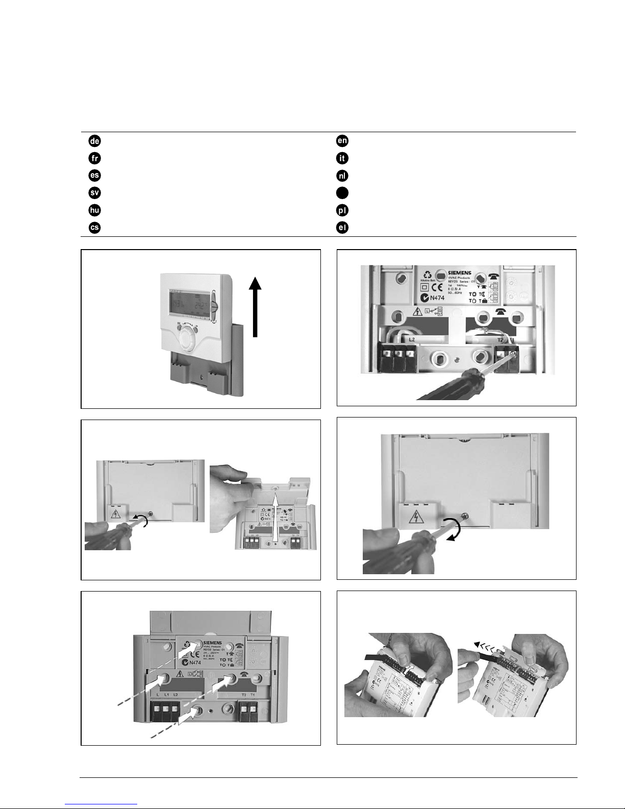
1 Montage
Gerät vom Sockel entfernen, Vorgehen gemäss Bild A. Für
die Montage Bilder B und C, siehe auch Montagehinweise
2 Verdrahtung prüfen
Die Anschlüsse sind im Kapitel "Anschlussschaltplan"
ersichtlich. Siehe auch Bilder D und E.
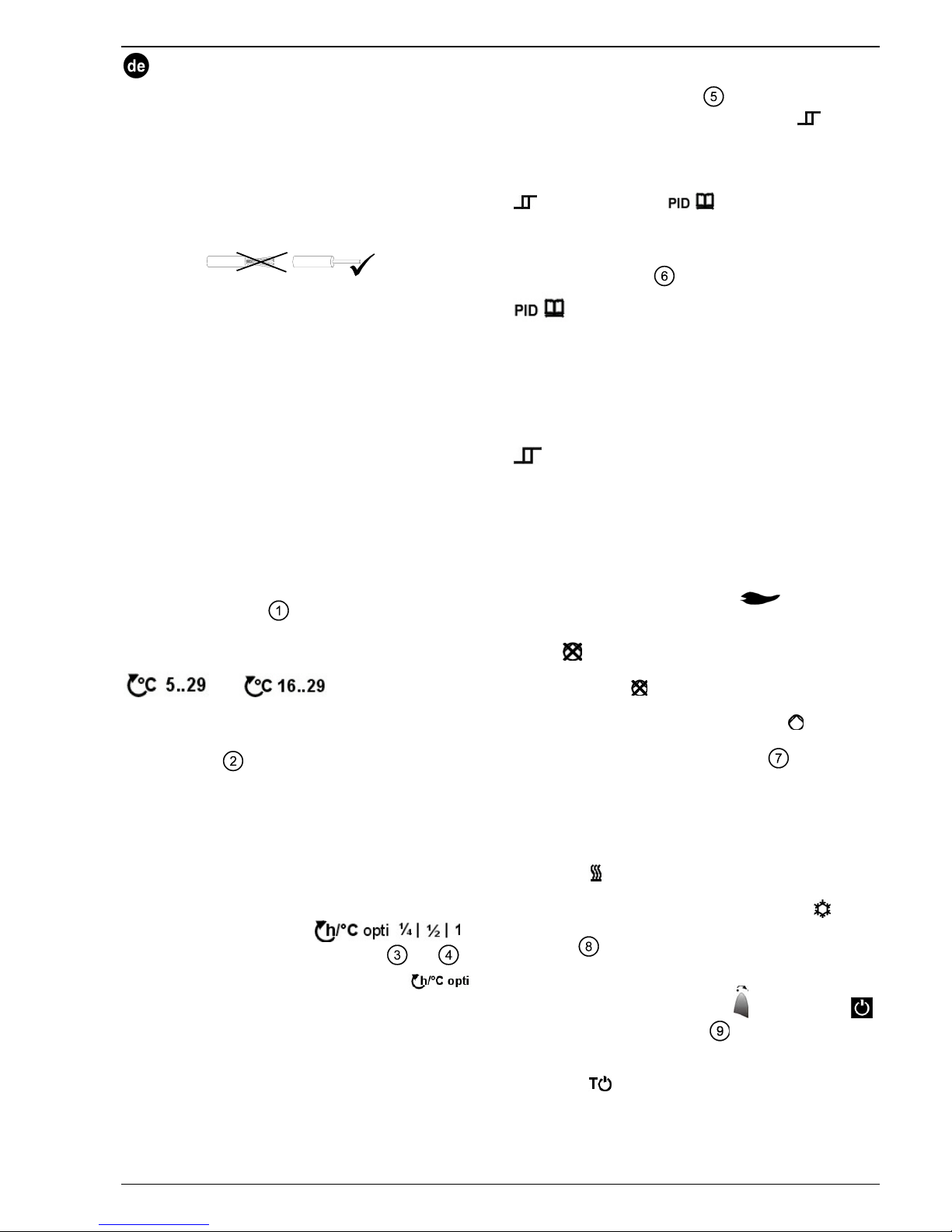
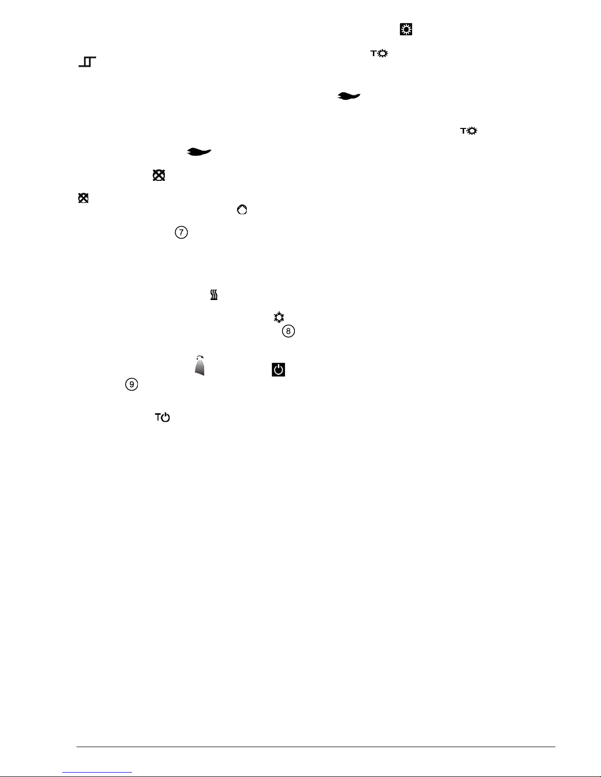
Hinweis: Keine Litzen verwenden, nur Volldraht oder
Litzen mit Aderendhülsen.
3 Isolierstreifen entfernen
Sobald der schwarze Isolierstreifen am Batteriekontakt
entfernt wird, ist das Gerät in Betrieb. Siehe auch Bild F.
4 Konfiguration
4.1 Einstieg in die Fachmannebene
Durch gleichzeitiges Drücken der Wärmer- und Kältertaste
sowie den Drehknopf zuerst im Gegenuhrzeigersinn,dann
im Uhrzeigersinn drehen, wird die Fachmannebene
freigegeben. Siehe auch Bild H.
4.2 Diverse Funktionen
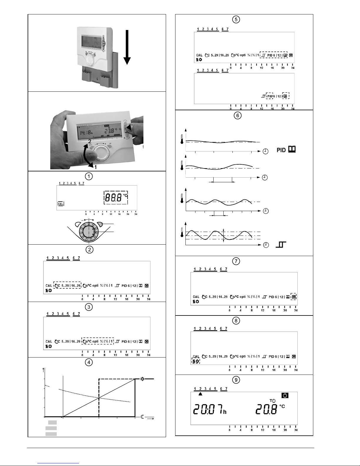
4.2.1 Fühler kalibrieren
Nach dem Aktivieren der Fachmannebene blinkt das
Symbol CAL. Durch Drücken auf den OK Knopf blinkt die
aktuell gemessene Temperatur und kann nun am
Drehknopf, um max. ± 2 °C neu kalibriert werden. Eingabe
speichern mit einem Druck auf den OK Knopf.
(siehe auch Abbildung
).
4.2.2 Sollwert-Begrenzung
2 Einstellmöglichkeiten
oder
In der Fachmannebene kann vom blinkenden CAL Symbol
mit einer Drehbewegung im Uhrzeigersinn auf das
Sollwertbegrenzungssymbol gewechselt werden (siehe
auch Abbildung
).
Durch Drücken auf die OK Taste akzeptieren. 5...29 °C
blinkt (Werkseinstellung). Durch Drücken akzeptieren oder
mit einer Drehbewegung im Uhrzeigersinn weiter.
Es blinkt die Einstellung 16...29 °C.
Durch Drücken der OK Taste akzeptieren.
4.2.3 Einschaltoptimierung
In der Fachmannebene kann vom blinkenden CAL Symbol
mit einer Drehbewegung im Uhrzeigersinn auf die
Einschaltoptimierungssymbole
gewechselt werden (siehe auch Abbildung
und ).
Durch Drücken auf die OK Taste akzeptieren,
(Werkseinstellung) blinkt, Optimierung ist ausgeschaltet.
Durch Drücken auf die OK Taste akzeptieren oder mit
weiteren Drehbewegung im Uhrzeigersinn Optimierung von
¼ h/°C, ½ h/°C oder 1 h/°C anwählen. Jeweils durch
Drücken auf die OK Taste akzeptieren.
4.2.4 Regelverhalten
In der Fachmannebene kann vom blinkenden CAL Symbol
mit mehreren Drehbewegung im Uhrzeigersinn auf die
Symbole der verschiedenen Regelalgorithmen gewechselt
werden (siehe auch Abbildung
).
Durch Drücken auf die OK Taste akzeptieren.
(Werkseinstellung) blinkt. Durch weiteres Drücken auf die
OK Taste akzeptieren oder mit jeder weiteren
Drehbewegung im Uhrzeigersinn die folgenden
Regelverhalten anwählen:
, PID 6, PID 12 oder . Gewünschtes
Regelverhalten durch Drücken auf die OK Taste
akzeptieren.
Beschreibung des Regelverhaltens siehe anschliessend.
(siehe auch Abbildung
).
Selbslernend
Adaptive Regelung: Für alle Anwendungen.
PID 12 Normale Regelstrecke:
Für Anwendungen an Orten mit normalen
Temperaturschwankungen.
PID 6 Schnelle Regelstrecke:
Für Anwendungen an Orten mit grossen
Temperaturschwankungen.
Schwierige Regelstrecke:
Reiner Zweipunktregler mit 0,5 °C Schaltdifferenz
(Werkseinstellung).
4.2.5 Periodischer Pumpenlauf
Diese Funktion schützt die Pumpe während längeren AUSPerioden vor einem möglichen Festsitzen. Der periodische
Pumpenlauf wird alle 24 Stunden um 12:00 Uhr für eine
Minute aktiviert (auf dem Display erscheint während dem
aktiven Pumpenlauf das Heizsymbol
).
In der Fachmannebene kann vom blinkenden CAL Symbol
mit zwei Drehbewegungen im Gegenuhrzeigersinn auf das
Symbol
gewechselt werden (Werkseinstellung
periodischer Pumpenlauf AUS). Durch Drücken auf die OK
Taste akzeptieren.
blinkt (Werkseinstellung), durch
Drücken auf die OK Taste akzeptieren oder mit einer
Drehbewegung weiter. Es blinkt das Symbol
periodischer Pumpenlauf EIN. Durch Drücken auf die OK
Taste akzeptieren (siehe auch Abbildung
).
4.2.6 Betriebsart Heizen oder Kühlen
In der Fachmannebene kann vom blinkenden CAL Symbol
mit einer Drehbewegungen im Gegenuhrzeigersinn auf die
Symbole Heizen / Kühlen gewechselt werden.
Durch Drücken auf die OK Taste akzeptieren, das
Heizsymbol
blinkt (Werkseinstellung), durch Drücken
auf die OK Taste akzeptieren oder mit einer
Drehbewegung weiter. Es blinkt das Kühlsymbol
, durch
Drücken auf die OK Taste akzeptieren (siehe auch
Abbildung
).
4.2.7 Schutzbetrieb
Mit dem Betriebsartenwahlschalter auf das Symbol
schalten (siehe auch Abbildung
).
Anpassen der Standardwerte (Fostschutz = 5 °C;
Überhitzungsschutz = 35 °C) erfolgt im Temperaturmenü T
bei Sollwert
(siehe auch Bedienungsanleitung).
5 Gerät wieder auf Sockel schieben
Vorgehen gemäss Bild G.
Siemens / Building Technologies / HVAC Products CE1G2216xx 21.06.2007 3/22
Page 4
6 Funktionskontrolle
a) Anzeige kontrollieren. Erscheint keine Anzeige muss
der Einbau und die Funktion der Batterien geprüft
werden
b) Betriebsart Komfort
c) Mit dem Temperaturmenü T den Temperatursollwert
auf 29 °C einstellen (siehe Bedienungsanleitung)
d) Das Relais und somit das Stellgerät müssen spätestens
nach einer Minute schalten. Das Symbol
erscheint auf dem Display. Ist dies nicht der Fall:
• Stellgerät und Verdrahtung prüfen
• Eventuell ist die Raumtemperatur höher als 29 °C
e) Sollwerttemperatur
wieder auf den ursprünglichen
Wert zurückstellen (Standardwert 19 °C oder eigene
Einstellung)
f) Gewünschte Betriebsart wählen
7 Reset
Benutzerdefinierte Daten:
Taste hinter der Nadelöffnung mindestens eine Sekunde
drücken: Dadurch werden die benutzerspezifischen
Einstellungen auf ihre Standardwerte zurückgesetzt (die
„Fachmann“-Einstellungen bleiben unverändert). Die Uhr
beginnt bei 12:00. Während der Resetzeit leuchten alle
Anzeigefelder des Displays, und können so überprüft
werden.
Alle benutzerdefinierten Daten plus Heizfachmann Einstellungen:
Taste hinter der Nadelöffnung zusammen mit der Wärmerund Kältertaste mindestens eine Sekunde drücken.
Nach diesem Reset werden die Werkseinstellungen neu
geladen (siehe auch Abschnitt „Werkseinstellungen“ in der
Bedienungsanleitung).
8 Hinweise
• REA23 ist ein elektronischer Raumtemperaturregler mit
Wochenschaltuhr.
• Der Regler gehört zur Softwareklasse A und ist für den
Gebrauch in einer Umgebung mit normalem
Verschmutzungsgrad vorgesehen.
• Sollten im Referenzraum thermostatische
Heizkörperventile installiert sein, müssen diese
vollständig geöffnet werden
• Der Fernbedienungskontakt muss getrennt, d.h. mit
einem separaten, abgeschirmten Kabel verdrahtet
werden
• Die örtlichen Vorschriften für Elektroinstallationen sind
einzuhalten
Commissioning
1 Mounting
Remove controller from its base by proceed according to
Fig. A.
For mounting, refer to Figs. B and C and “Mounting notes“.
2 Check wiring
For the electrical connections, refer to “Connection
diagram“ (also refer to Figs. D and E).
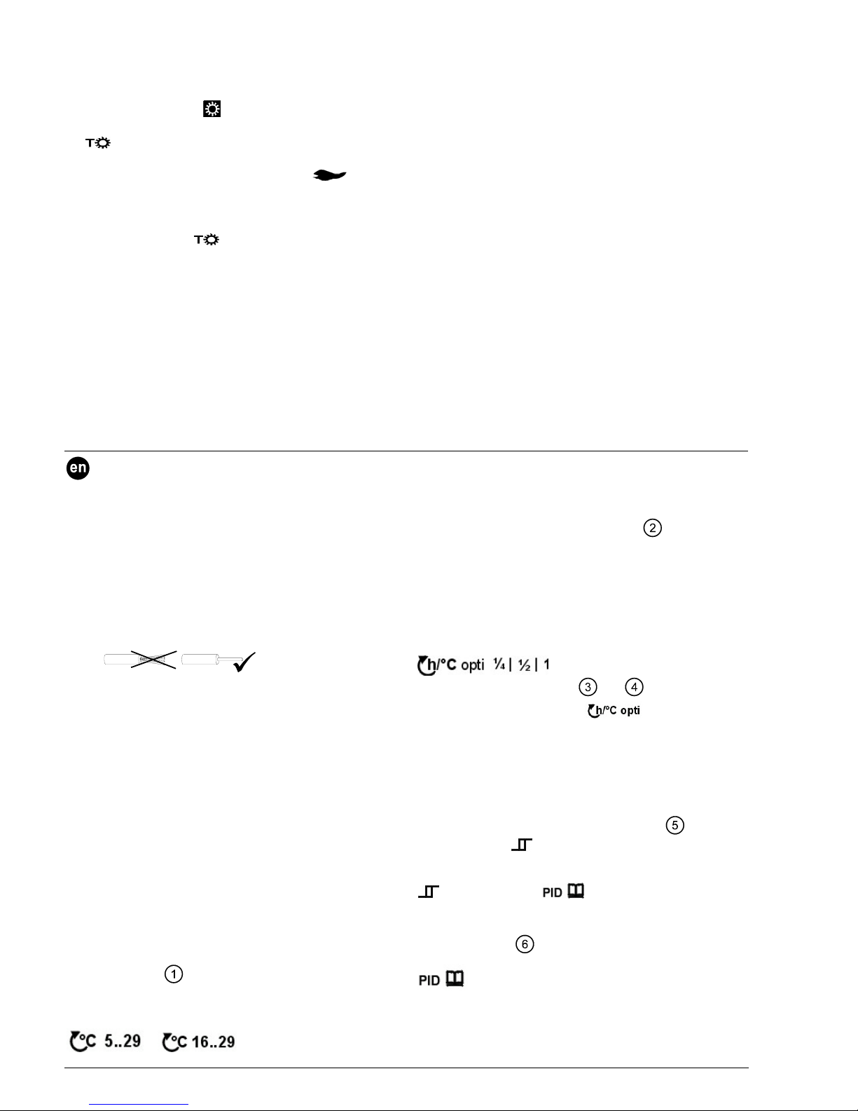
Note: Do not use stranded wires, only solid wires or
stranded wires with ferrules.
3 Remove the battery transit tab
As soon as the battery transit tab is removed, the controller
starts to operate (also refer to Fig. F).
4 Configuration
4.1 Accessing the heating engineer level
The heating engineer level will be enabled by pressing
simultaneously the warmer and colder buttons and by
turning the setting knob counter-clockwise and then
clockwise (also refer to Fig. H).
4.2 Functions
4.2.1 Calibrating the temperature sensor
After activating the heating engineer level, the CAL symbol
will flash. When pressing the OK-knob, the room
temperature currently measured flashes and can now be
recalibrated by a maximum of ± 2 °C by turning the setting
knob. To store the recalibration, press the OK-knob
(also refer to Fig.
).
4.2.2 Setpoint limitation
There are 2 setting choices available:
or
On the heating engineer level, change from the flashing
CAL symbol to the setpoint limitation symbol by turning the
setting knob clockwise (also refer to Fig.
).
Press the OK-knob to accept. 5...29 °C will flash (factory
setting). Press the OK-knob to accept or continue turning.
Setting 16...29 °C will flash.
Press the OK-knob to accept.
4.2.3 Optimum start control
On the heating engineer level, change from the flashing
CAL symbol to the optimum start control symbols
by turning the setting knob
clockwise (also refer to Figs.
and ).
Press the OK-knob to accept.
(factory setting)
will flash, optimization is switched off. Press the OK-knob
to accept or continue turning until you reach ¼ h/°C,
½ h/°C or 1 h/°C. Press the OK-knob to accept.
4.2.4 Control mode
On the heating engineer level, change from the flashing
CAL symbol to the symbols of the various control modes
by turning the setting knob (also refer to Fig.
).
Press to accept.
(factory setting) will flash. Press the
OK-knob to accept or continue turning the setting knob to
select one of the following control modes:
, PID 6, PID 12 or . Press the OK-knob to
accept the required control mode.
A brief description of the control modes is given below
(also refer to Fig.
).
Self-learning
Adaptive control: Suited for all standard
applications.
PID 12 Normal controlled systems:
For locations with normal temperature variations.
4/22 21.06.2007 CE1G2216xx Siemens / Building Technologies / HVAC Products
Page 5
PID 6 Fast controlled systems:
For locations with significant temperature
variations.
Difficult controlled systems:
Proper on / off controller with a switching
differential of 0.5 C.
(factory setting)
4.2.5 Periodic pump run
This function protects the pump against seizing during
longer off periods. Periodic pump run is activated for one
minute every 24 hours at 12:00 (when pump run is
activated, the flame symbol
appears on the display).
On the heating engineer level, change from the flashing
CAL symbol to the
symbol by turning the setting knob
(factory setting, periodic pump run off). Press to accept.
will flash (factory setting). Press the OK-knob to accept
or continue turning the setting knob. The
symbol for
periodic pump run on will flash. Press the OK-knob to
accept (also refer to Fig.
).
4.2.6 Heating / cooling mode
On the heating engineer level, change from the flashing
CAL symbol to the heating / cooling symbols by turning the
setting knob.
Press the OK-knob to accept, the
heating symbol will
flash (factory setting). Press the OK-knob to accept or continue turning the setting knob. The cooling symbol
will
flash. Press the OK-knob to accept (also refer to Fig
).
4.2.7 Protection mode
Use operating mode selector to select symbol (also
refer to Fig.
).
Adjustment of standard values (frost protection = 5 °C;
overheat protection = 35 °C) being done in temperature
menu T by setpoint
(refer to Operating Instructions).
5 Replacing the controller on its base
Proceed according to Fig. G.
6 Functional check
a) Check the display. If there is no display, check the
correct fitting and function of the batteries.
b) Comfort mode
c) Select temperature menu T and adjust the temperature
setpoint
to 29 °C (refer to the Operating
Instructions)
d) The relay must be energized and thus the actuating
device activated within one minute. Flame symbol
will appear on the display. If that is not the case:
• Check actuating device and wiring
• The room temperature is possibly above 29 °C
e) Reset the setpoint temperature
to the initial value
(standard value 19 °C or individual setting)
f) Select the required operating mode
7 Reset
User-defined data:
Press the button behind the pin opening for at least one
second: this resets the user-specific settings to their default
values (the heating engineer settings will not be changed).
The clock starts at 12:00. During the reset time, all sections
of the display light up, enabling them to be checked.
All user-defined data plus the heating engineer
settings:
Press the button behind the pin opening together with the
warmer and colder buttons for at least one second.
After this reset, the factory settings will be reloaded (also
refer to section “Factory settings“ in the operating
instructions).
8 Notes
• REA23 is an electric weekly programmable room
temperature controller.
• The controller conforms to “Software Class A” and is for
use in “normal” pollution situation.
• If the reference room is equipped with thermostatic
radiator valves, they must be set to their fully open
position
• The remote operation contact T1 / T2 must be wired
separately using a separate screened cable
• Ensure that the local regulations for electrical
installations are complied with
Siemens / Building Technologies / HVAC Products CE1G2216xx 21.06.2007 5/22
Page 6
Mise en service
1 Montage
Retirez l'appareil de son socle, procédez comme indiqué
figure A. Pour le montage, référez-vous aux figures B et C
(voir également les instructions de montage)
2 Vérifier le câblage
Les raccordements sont indiqués dans le chapitre
"Schéma de raccordement". Voir aussi figures D et E.
Remarque : ne pas utiliser de fils tressés, uniquement des
fils ronds ou des fils avec cosses.
3 Retirer la bande isolante
Dès que la bande isolante noire est retirée du contact des
piles, l'appareil se met en marche. Voir aussi figure F.
4 Configuration
4.1 Accès au niveau "Chauffagiste"
En appuyant simultanément sur les touches "plus chaud"
et "plus froid" et en tournant le bouton d'abord dans le sens
contraire des aiguilles d'une montre, et ensuite dans le
sens des aiguilles d'une montre, l'appareil libère l'accès au
niveau chauffagiste. Voir aussi figure H.
4.2 Fonctions diverses
4.2.1 Calibrer la sonde
Dès l'entrée au niveau Chauffagiste, le symbole CAL
clignote. En appuyant sur le bouton OK la température
actuelle clignote et peut être réajustée en tournant le
bouton de réglage de ± 2 °C max. Valider l'entrée en
appuyant sur le bouton OK (voir aussi figure
).
4.2.2 Limitation du point de consigne
2 possibilités de réglage
ou
Au niveau "Chauffagiste" : passez du symbole CAL au
symbole de limitation de consigne en tournant le bouton
dans le sens des aiguilles d'une montre (voir aussi figure
).
Appuyez sur la touche OK pour valider. 5...29 °C clignote
(réglage usine). Appuyez pour accepter ou continuez de
tourner dans le sens des aiguilles d'une montre.
Le réglage 16...29 °C clignote.
Appuyez sur la touche OK pour valider.
4.2.3 Enclenchement optimisé
Au niveau "Chauffagiste" : passez du symbole CAL au
symbole d'optimisation de l'enclenchement
en tournant le bouton dans le sens
des aiguilles d'une montre (voir aussi figure
et ).
Appuyez sur la touche OK pour valider,
(réglage usine) clignote, l'optimisation est arrêtée. Appuyez
sur la touche OK pour validez ou continuez de tourner
dans le sens des aiguilles d'une montre pour sélectionner
une optimisation de 1/4 h/°C, 1/2 h/°C ou 1 h/°C. Appuyez
à chaque fois sur la touche OK pour valider.
4.2.4 Mode de régulation
Au niveau "Chauffagiste", vous pouvez accéder aux
symboles des différents algorithmes de régulation à partir
du symbole CAL en tournant le bouton dans le sens des
aiguilles d'une montre
(voir aussi figure
).
Appuyez sur la touche OK pour valider.
(réglage
usine) clignote. Appuyer de nouveau sur la touche OK pour
valider ou continuez de tourner dans le sens des aiguilles
d'une montre pour sélectionner l'un de ces modes de
régulation :
, PID 6, PID 12 ou . Validez le mode de
régulation souhaité en appuyant sur la touche OK.
Description du comportement de réglage ci-après (voir
aussi figure
).
Auto-adaptation
Régulation auto-adaptative: pour toutes les
applications.
PID 12 Boucle de régulation usuelle :
pour installations sujettes à des variations de
température ordinaires.
PID 6 Boucle de régulation rapide :
pour installations sujettes à des variations de
température importantes.
Boucle de régulation difficile :
Régulateur tout-ou-rien avec différentiel de 0,5°C
(réglage usine).
4.2.5 Relance périodique de la pompe
Cette fonction évite un grippage éventuel de la pompe
durant les périodes d'arrêt prolongé. La pompe est
relancée toutes les 24 heures à 12:00 heures pendant une
minute (l'écran affiche le symbole
).
Au niveau "Chauffagiste" : passez du symbole CAL au
symbole
en tournant deux fois le bouton dans le sens
contraire des aiguilles d'une montre (réglage usine: relance
périodique des pompes désactivée). Appuyez sur la
touche OK pour valider.
clignote (réglage usine) ;
appuyez sur la touche OK pour valider ou continuez de
tourner. Le symbole
de relance périodique clignote.
Appuyez sur la touche OK pour valider (voir aussi figure
).
4.2.6 Régime de chauffage ou de refroidissement
Au niveau "Chauffagiste" : passez du symbole CAL au
symbole chauffage/refroidissement en tournant le bouton
dans le sens contraire des aiguilles d'une montre.
Appuyer sur la touche OK pour valider. Le symbole de
chauffage
clignote (réglage usine) ; appuyez sur la
touche OK pour valider ou continuez de tourner. Le
symbole de refroidissement
clignote ; appuyez sur la
touche OK pour valider (voir aussi figure
).
4.2.7 Régime hors-gel
Avec le sélecteur de régime , passez au symbole
(voir aussi figure
).
L'adaptation des valeurs standards (hors-gel = 5 °C;
protection contre la surchauffe = 35 °C) s'effectue dans le
menu température T avec la consigne
(voir aussi
mode d'emploi).
6/22 21.06.2007 CE1G2216xx Siemens / Building Technologies / HVAC Products
Page 7

5 Replacer l'appareil sur son socle
Procédez comme indiqué figure G.
6 Contrôle des fonctions
a) Vérifiez l'affichage. Si l'écran reste vide, vérifiez que les
piles sont en place et fonctionnent
b) Régime Confort
c) Réglez dans le menu température T la consigne
sur 29 °C (voir mode d'emploi)
d) Le relais, et donc l'organe de réglage doivent commuter
après une minute au plus tard. Le symbole
est
affiché. Si cela n'est pas le cas :
• Vérifiez l'organe de réglage et le câblage
• La température ambiante est peut-être supérieure à
29 °C
e) Remettre
sur la valeur initiale (valeur par défaut 19
°C ou réglage personnalisé).
f) Sélectionnez le régime souhaité.
7 Réinitialisation (Reset)
Données utilisateur :
Appuyez pendant une seconde minimum sur la touche
marquée reset (trou d'épingle) : les réglages utilisateur
sont ramenés aux valeurs standard (les réglages
"Chauffagiste" restent inchangés). Pendant le temps de
réinitialisation, tous les champs de l'afficheur s'allument, ce
qui permet de vérifier leur fonctionnement.
Réinitialisation de tous les réglages chauffagiste et
utilisateur:
Appuyez simultanément sur la touche reset (trou d'épingle)
et sur les touches "plus chaud" et "moins chaud".
Les réglages d'usine sont alors rechargés (voir aussi le
chapitre correspondant du mode d'emploi).
8 Remarques :
• Le REA23 est un régulateur électronique de
température ambiante avec une horloge hebdomadaire.
• Il fait partie de la classe A des logiciels et est prévu
pour fonctionner dans un environnement présentant un
degré d'encrassement normal.
• Si des vannes thermostatiques sont installées dans la
pièce de référence, elles doivent être ouvertes au
maximum
• Le contact de commande à distance doit être câblé
séparément avec un câble blindé distinct.
• Respecter les prescriptions locales pour les installations
électriques.
• Respecter les réglementations locales pour les
installations électriques.
Messa in servizio (Discription of REV23)
1 Installazione
Rimuovere il regolatore dalla basetta come mostrato in
fig. A.; per l’installazione procedere facendo riferimento alle
fig. B e C.
(fare rif. alle "Note di montaggio")
2 Collegamenti elettrici
Per i collegamenti elettrici, fare riferimento alla sezione
“schema di collegamento“ (rif. Fig. D e E).
Note: si consiglia di utilizzare dei capicorda per effettuare i
collegamenti elettrici alla morsettiera del regolatore
3 Rimozione della linguetta di protezione
Rimuovendo la linguetta nera di protezione dalle batterie, il
regolatore si accende automaticamente. (rif. Fig. F).
4 Configurazione
4.1 Accesso al livello tecnico
Il livello tecnico si attiva premendo contemporaneamente i
pulsanti per la modifica del valore del setpoint (+ aumento
e - diminuzione) e facendo scorrere il tasto di scorrimento
prima verso il basso e poi verso l’alto. (rif. Fig. H).
4.2 Parametri di controllo
4.2.1 Calibrazione della sonda
Dopo aver attivato il livello tecnico, il display visualizza una
serie di parametri di controllo che possono essere
modificati. Il primo che appare, lampeggiando, sulla sinistra
è il simbolo CAL (calibrazione sonda). Premere il pulsante
di scorrimento per visualizzare la temperatura ambiente
attualmente misurata, a questo punto è possibile ricalibrare
la sonda per un massimo di ± 2 °C. Per modificare il
valore muovere il pulsante di scorrimento verso l’alto
(aumento) o verso il basso (diminuzione). Per confermare
la ricalibrazione premere il pulsante di scorrimento. (rif. Fig.
).
4.2.2 Campo di lavoro del setpoint
Il regolatore permette di selezionare 2 differenti campi di
lavoro del setpoint:
o
Attivare il livello tecnico, una volta visualizzato a display il
simbolo CAL muovere il pulsante di scorrimento verso
l‘alto per passare al livello del campo di lavoro del setpoint.
A questo punto appare lampeggiando il campo di lavoro
5...29 °C (Impostazione di fabbrica). Premere il pulsante di
scorrimento per confermare oppure scorrere per
selezionare l’altro campo di lavoro disponibile.
L’altro campo di lavoro 16...29 °C appare lampeggiando.
Premere il pulsante di scorrimento per confermare il campo
di lavoro selezionato. (rif. Fig.
).
4.2.3 Ottimizzazione
Nel livello tecnico, scorrere verso il basso dal simbolo CAL
fino ad arrivare al simbolo dell'ottimizzazione
(rif. fig. e ).
Siemens / Building Technologies / HVAC Products CE1G2216xx 21.06.2007 7/22
Page 8

Premere il pulsante per entrare nel parametro. Il simbolo
lampeggierà (impostazione di fabbrica).
Premere per confermare o scorrere per cambiare valore a
½, 1 o escludere l'ottimizzazione
. Premere per
confermare l'impostazione.
4.2.4 Modalità di regolazione PID
Una volta entrati nel livello tecnico, scorrere verso il basso
dal livello CAL fino ad arrivare al livello delle modalità di
regolazione PID. (rif. Fig.
).Premere il pulsante di
scorrimento per entrare nel parametro dove appare
lampeggiando il controllo autoadattante
(settaggio di fabbrica).
Premere il pulsante di scorrimento (fig.3) per confermare il
valore oppure scorrere verso il basso per selezionare una
tra le seguenti modalità di regolazione:
, PID 6, PID 12 o .
Una volta selezionata la modalità di regolazione richiesta,
premere il pulsante di scorrimento per confermare.
La scelta della modalità di regolazione può essere
agevolata seguendo la descrizione sottostante
(rif. Fig.
).
Auto-adattante:
adatto a tutte le applicazioni standard
(Settaggio di fabbrica).
PID 12 Impianti con regolazione normale:
per ambienti laddove le variazioni di temperatura
sono normali.
PID 6 Impianti con regolazione veloce:
per ambienti laddove le variazioni di temperatura
sono significanti.
Impianti con regolazione difficile:
funzionamento a 2 punti, differenziale di 0.5 °C.
4.2.5 Funzionamento periodico della pompa
Questa funzione protegge la pompa da eventuale
grippaggio dovuto a lunghi periodi di chiusura. Il
funzionamento periodico della pompa viene attivato per un
minuto ogni 24 ore alle ore 12:00 (quando la funzione è
attiva appare a display il simbolo
).
Per attivare la funzione occorre entrare nel livello tecnico,
scorrere verso il basso dal simbolo CAL fino ad arrivare al
simbolo
(Funzione esclusa). Premere per entrare nel
parametro. Il simbolo
lampeggia a display
(impostazione di fabbrica). Premere per confermare o
scorrere sul simbolo
(funzione attiva) che lampeggierà
a display. Premere per confermare. (rif. Fig.
).
4.2.6 Riscaldamento / raffreddamento
Nel livello tecnico, scorrere verso il basso dal simbolo CAL
fino ad arrivare al simbolo riscaldamento / raffreddamento
/ .
Premere per entrare nel parametro, il simbolo di
riscaldamento
lampeggia (impostazione di fabbrica).
Premere per confermare o scorrere sul simbolo di
raffreddamento
che lampeggierà. Premere per
confermare (rif. Fig
).
4.2.7 Protezione antigelo
Utilizzare il selettore di regime di funzionamento per
selezionare la protezione antigelo
(rif. Fig. ).
Se fosse necessario modificare il setpoint
di 5 °C
(settaggio di fabbrica), occorre entrare nel menù T
(rif. Istruzioni operative).
5 Sostituzione del regolatore
Procedere facendo riferimento alla Fig. G.
6 Controllo funzionale
a) Verificare il funzionamento del display. Se il display non
si dovesse accendere controllare il corretto
posizionamento delle batterie.
b) Selezionare il regime di comfort
c) Selezionare il menù T ed impostare il setpoint di
comfort
fino a 29 °C (rif. Istruzioni operative)
d) Entro un minuto il relè viene eccitato chiudendo il
contatto di comando. Quando il contatto chiude appare
a display il simbolo
.
e) Se questo non avviene probabilmente:
la temperatura ambiente è superiore a 29 °C
f) Reimpostare il setpoint di comfort
al settaggio di
fabbrica (valore standard 19 °C)
g) Selezionare il regime di funzionamento richiesto.
7 Reset
Premendo il pulsante di reset posizionato sul retro per
almeno un secondo, tutte le impostazioni effettuate
vengono annulate e il regolatore ritorna ai valori di fabbrica
(i parametri impostati nel livello tecnico non vengono
cancellati). L'orologio ripartirà dalle ore 12:00. Durante il
reset, vengono visualizzati a display tutti i digit disponibili.
Premendo il pulsante di reset posizionato sul retro, tutte le
impostazioni effettuate vengono annullate e il regolatore
ritorna ai valori di fabbrica
8 Note
• Il REV12 è un regolatore ambiente con
programmazione giornaliera.
• Il regolatore è conforme a “Software di Classe A ” ed è
progettato per lavorare in situazioni di inquinamento
“normale”.
• Se l’ambiente di riferimento presenta delle valvole
termostatiche sui radiatori, posizionarle tutte in
apertura.
• Il contatto per il comando telefonico T1/T2 deve essere
collegato separatamente.
• Rispettare le norme vigenti per effettuare i collegamenti
elettrici
8/22 21.06.2007 CE1G2216xx Siemens / Building Technologies / HVAC Products
Page 9

Puesta en servicio
1 Montaje
Separar el controlador de su base según la Fig. A.
Para montaje, ver las Figs. B y C y “Notas de montaje“.
2 Verificación del cableado
Para conexiones eléctricas, ver “Esquemas de
conexionado“ (ver también las Figs. D y E).
Nota: Utilice cable flexible con terminal o hilo rígido.
3 Retirar la banda protectora de las pilas
Una vez retirada la banda protectora, el controlador
empieza a funcionar (ver también la Fig. F).
4 Configuración
4.1 Acceso a los ajustes de configuración
Se activan pulsando simultáneamente los botones de más
(+) y menos (-) y girando el selector en sentido contrario a
las agujas del reloj, y luego en el sentido de las agujas del
reloj (ver también la Fig. H).
4.2 Funciones
4.2.1 Calibración de la sonda de temperatura
Tras activar los ajustes de configuración, parpadea el
símbolo CAL. Al pulsar el botón OK, la temperatura
ambiente actualmente medida parpadea y puede ser
recalibrada en un máximo de ± 2 °C girando el selector.
Para guardar la recalibración, pulsar el botón OK (ver
también la Fig.
).
4.2.2 Limitación de consigna
Existen 2 escalas de ajuste:
o
En el programa de configuración, cambiar del símbolo
parpadeante CAL al símbolo de limitación de consigna
girando el selector en sentido horario. (ver también la Fig.
).
Pulsar el botón OK para aceptar. 5...29 °C parpadea
(ajuste de fábrica). Pulsar el botón OK para aceptar o girar
para cambiar.
El ajuste 16...29 °C parpadea.
Pulsar el botón OK para aceptar.
4.2.3 Control de arranque optimizado
En el programa de configuración, cambiar del símbolo
parpadeante CAL a los símbolos de control de arranque
optimizado
girando el selector en
sentido horario (ver también las Figs.
y ).
Pulsar el botón Ok para aceptar.
parpadeará
(ajuste de fábrica). Pulsar el botón OK para aceptar o girar
hasta que se alcance ¼ h/°C,
½ h/°C o 1 h/°C 1. Pulsar el botón OK para aceptar.
4.2.4 Modo de control
En el programa de configuración, cambiar del símbolo
parpadeante CAL a los símbolos de los diferentes modos
de control, girando el selector (ver también la Fig.
).
Pulsar para aceptar.
(ajuste de fábrica) parpadea.
Pulsar el botón Ok para aceptar o girar el selector para
seleccionar uno de los siguientes modos de control:
, PID 6, PID 12 o . Pulsar el botón OK para
aceptar el modo de control requerido.
Abajo se ofrece una breve descripción de los modos de
control (ver también la Fig.
).
Self-learning, control autoadaptativo:
Apropiado para todas las aplicaciones estándar.
PID 12 Sistemas de control normal:
Para lugares con variaciones normales de
temperatura.
PID 6 Sistemas de control rápido:
Para lugares con variaciones importantes de
temperatura.
Sistemas de control difícil:
Controlador todo/nada con un diferencial de
conmutación de 0.5 C.
(ajuste de fábrica)
4.2.5 Funcionamiento periódico de la bomba
Esta función protege la bomba contra gripaje después de
largos periodos de inactividad. El funcionamiento periódico
de la bomba se activa durante un minuto cada 24 horas a
las 12:00 (cuando se activa la bomba, aparece el símbolo
de llama
en la pantalla).
En el programa de configuración, cambiar del símbolo
parpadeante CAL al símbolo
girando el selector (ajuste
de fábrica, desconexión periódica de la bomba). Pulsar
para aceptar.
parpadeará (ajuste de fábrica). Pulsar el
botón OK para aceptar o girar el selector. El símbolo
de
funcionamiento periódico de la bomba parpadeará. Pulsar
el botón OK para aceptar (ver también la Fig.
).
4.2.6 Modo Calefacción / refrigeración
En el programa de configuración, cambiar del símbolo
parpadeante CAL a los símbolos de calefacción /
refrigeración, girando el selector.
Pulsar el botón OK para aceptar, el símbolo de calefacción
parpadea (ajuste de fábrica). Pulsar el botón OK para
aceptar o girar para cambiar. El símbolo de refrigeración
parpadeará. Pulsar el botón OK para aceptar (ver
también la Fig
).
4.2.7 Modo protección antihielo
Utilizar el selector de modo de operación para
seleccionar el símbolo
(ver también la Fig. ). El
ajuste de los valores estándar (protección antihielo = 5 °C;
protección sobrecalentamiento = 35 °C) se realiza en el
menú de temperatura T con la consigna
(ver
Instrucciones de manejo).
5 Colocar el controlador en su base
Proceder según la Fig. G.
6 Verificación de funciones
a) Verificar la pantalla. Si no se muestra nada en la
pantalla, verificar el correcto contacto y posición de las
pilas.
b) Modo confort
Siemens / Building Technologies / HVAC Products CE1G2216xx 21.06.2007 9/22
Page 10

c) Seleccionar el menú de temperatura T y ajustar la
consigna de temperatura
en 29 °C (ver
Instrucciones de Manejo)
d) El relé debe estar energizado y, por lo tanto, la unidad
de regulación activada antes de un minuto. El símbolo
aparece en la pantalla. Si no es éste el caso:
• Verificar la unidad de regulación y el cableado
• La temperatura ambiente puede ser superior a
29 °C
e) Reajustar la temperatura de consigna
en el valor
inicial (valor estándar 19 °C o ajuste individual)
f) Seleccionar el modo de operación requerido
7 Reset
Parámetros introducidos por el usuario:
Pulsar el botón que hay en la parte posterior durante al
menos un segundo: esto modifica los parámetros
introducidos por el usuario a sus valores por defecto de
fábrica. (Los parámetros de instalación no se modificarán).
El reloj arranca a las 12:00. Durante el tiempo de reajuste,
todas las secciones de la pantalla se iluminan,
posibilitando su verificación.
Todos los parámetros introducidos por el usuario más
los parámetros de instalación:
Pulsar el botón que hay en la parte posterior al tiempo que
los botones más (+) y menos (-) durante al menos un
segundo. Tras este reajuste, los parámetros de fábrica
volverán a cargarse (ver también “Ajustes de fábrica” en
las Instrucciones de Manejo).
8 Notas
• REA23 es un controlador electrónico de temperatura
con programación semanal.
• El controlador está conforme con “Software Class A” y
se utiliza en situaciones de polución “normal”.
• Si la habitación de referencia está equipada con
válvulas termostáticas de radiador, éstas deben estar
en posición totalmente abierta
• El contacto para mando remoto T1 / T2 debe cablearse
por separado utilizando un cable apantallado
independiente
• Garantizar que se cumplen las normas locales para
instalaciones eléctricas
Inbedrijfstelling
1 Montage
Het apparaat van de sokkel afnemen, handelen volgens
afb. A. Zie voor montage afb. B en C, zie ook de
aanwijzingen voor montage.
2 Bedrading controleren
Een mogelijke aansluiting is weergegeven in hoofdstuk
"Aansluitschema’s", echter bij veel ketels kan L en L1
rechtstreeks op de thermostaatklemmen van de ketel
worden aangesloten. Zie ook afb. D en E.
Aanwijzing: geen gevlochten draad gebruiken, alleen
massief draad of gevlochten draad met adereindhulzen.
3 Isolatiestrook verwijderen
Zodra de zwarte isolatiestrook van het batterijcontact wordt
verwijderd, is het apparaat in bedrijf. Zie ook afb. F.
4 Configuratie
4.1 Toegang tot het installateursniveau
Door het gelijktijdig indrukken van de verwarmings- en
koeltoets en het draaiknop eerst tegen klokrichting in,
daarna met klokrichting meedraaien, wordt het
installateusniveau weergegeven. Zie ook afb. H.
4.2 Diverse functies
4.2.1 Opnemer kalibreren
Na het activeren van het installateursniveau, knippert het
symbool CAL. Door drukken op de OK knop knippert de
actueel gemeten temperatuur en deze kan nu door
draaiknop met ± 2 °C opnieuw worden gecalibreerd. De
waarde opslaan met een druk op de OK knop.
(zie ook afbeelding
).
4.2.2 Begrenzing van de gewenste waarde
2 Instelmogelijkheden
of
Op het installateursniveau kan men het knipperende CAL-
symbool met een draaibeweging in klokrichting de display
overschakelen naar het begrenzingssymbool voor de
gewenste waarde (zie ook afbeelding
).
Bevestigen door in te drukken OK toets 5...29 °C knippert
(fabrieks-instelling). Door in te drukken bevestigen of met
een draaibeweging in klokrichting de instelling 16...29 °C
knippert.
Door in te drukken OK toets bevestigen.
4.2.3 Inschakeloptimalisering
Op het installateusniveau kan men van het knipperende
CAL- symbool met een draaibeweging in klokrichting
overschakelen naar de optimaliseringssymbolen voor het
inschakelen
(zie ook afbeelding
en ).
Door drukken op de OK toets accepteren,
(fabrieksinstelling) knippert, Optimalisering is
uitgeschakeld. Door drukken op de OK toets accepteren of
met een volgende draaibeweging in klokrichting
optimalisering van ¼ h/°C, ½ h/°C of 1 h/°C kiezen.
Telkens accepteren d.m.v. drukken op OK toets.
4.2.4 Regelgedrag
Op het installateursniveau kan men van het knipperende
CAL-symbool met verschillende draaibeweging in
klokrichting overschakelen naar de symbolen van
verschillende regelalgoritmen (zie ook afbeelding
).
Door drukken op de OK toets accepteren.
(fabrieksinstelling) knippert. Door drukken op de OK toets
accepteren of met iedere verdere draaibeweging in
klokrichting het volgende regelgedrag kiezen:
, PID 6, PID 12 of . Gewenste regelgedrag door
drukken op de OK toets accepteren. Zie hierna voor de
bevestiging van het regelgedrag (zie ook afbeelding
).
Zelflerend
Adaptieve regeling: voor alle toepassingen.
10/22 21.06.2007 CE1G2216xx Siemens / Building Technologies / HVAC Products
Page 11

PID 12 Normaal regeltraject:
voor toepassing op plaatsen met normale
temperatuurschommelingen.
PID 6 Snel regeltraject:
voor toepassingen op plaatsen met grote
temperatuurschommelingen.
Moeilijk regeltraject:
zuivere tweepuntsregeltraject met 0,5 °C
schakeldifferentie (fabrieksinstelling).
4.2.5 Periodiek draaien van de pomp
Deze functie beveiligt de pomp tijdens langere perioden
van buitenbedrijfstelling tegen eventueel vastzitten.
Het periodiek draaien van de pomp wordt iedere 24 uur om
12:00 uur gedurende een minuut geactiveerd (op de
display verschijnt tijdens deze activiteit het symbool
).
Op het installateursniveau kan men van het knipperende
CAL-symbool met twee draaibewegingen tegen
klokrichting in af overschakelen naar het symbool
(fabrieksinstelling periodiek draaien van de pomp UIT).
Door drukken op de OK toets accepteren.
knippert
(fabrieksinstelling) door drukken op de OK toets
accepteren of met een draaibewegingen in verder gaan.
Het symbool
knippert, periodiek draaien van de pomp
AAN. Door drukken op de OK toets accepteren
(zie ook afbeelding
).
4.2.6 Bedrijfswijze verwarmen of koelen
Op het installateursniveau kan men van het knipperende
CAL-symbool met een draaibewegingen tegen klokrichting
in af overschakelen naar de symbolen verwarmen / koelen.
Door drukken op de OK toets accepteren, het
verwarmingssymbool
knippert (fabrieksinstelling), door
drukken op de OK toets accepteren of met een
draaibeweging verder gaan. Het koelsymbool
knippert,
Door drukken op de OK toets accepteren (zie ook
afbeelding
).
1.1.1 Bewakingsbedrijf
Met de bedrijfskeuzeschakelaar op het symbool
schakelen (zie ook afbeelding
).
Aanpassen van de standaard waarde (vorstbescherming =
5 °C; oververhittingsbescherming = 35 °C) geschiedt in het
temperaturmenu T bij gewenste waarde
(zie ook
bedienigshandleiding).
5 Apparaat weer op de sokkel schuiven
Handelen volgens afbeelding G.
6 Functiecontrole
a) Weergave controleren. Als er geen weergave
verschijnt, moeten de plaatsing en de functie van de
batterijen worden gecontroleerd
b) Bedrijfswijze comfort
c) Met het temperatuurmenu T de gewenste
temperatuurwaarde
instellen op 29 °C (zie de
handleiding voor bediening)
d) Het relais en daarmee het verwarmingstoestel moeten
minstens na een minuut schakelen. Het symbool
verschijnt op de display. Als dit niet het geval is:
• De instelling en de bedrading controleren
• Eventueel is de ruimtetemperatuur hoger dan 29 °C
e) Gewenste temperatuurwaarde
weer terugzetten
naar de oorspronkelijke waarde (standaardwaarde
19 °C of eigen instelling)
f) Gewenste bedrijfswijze kiezen
7 Reset
Door de gebruiker gedefinieerde gegevens:
De toets achter de naaldopening minstens een
seconde indrukken:
daardoor worden de voor de gebruiker specifieke
instellingen teruggezet op hun standaardwaarden (de
"Instellingen van de installateur " blijven onveranderd). De
klok begint bij 12:00. Tijdens de resettijd branden alle
weergavevelden van de display en kunnen worden
gecontroleerd.
Alle door de gebruiker gedefinieerde gegevens plus de
instellingen van de installateur:
de toets achter de naaldopening, samen met de toets voor
warmer en kouder minstens een seconde indrukken.
Na deze reset worden de fabrieksinstellingen opnieuw
geladen (zie ook de sectie "Fabrieksinstellingen" in de
handleiding voor de bediening).
8 Aanwijzingen
• De REA23 is een elektronische ruimtetemperatuurregelaar met weekschakelklok
• De regelaar behoort tot de softwareklasse A en is
geconstrueerd voor gebruik in een omgeving met
normale vervuilingsgraad
• Als in de referentieruimte thermostatische radiatorafsluiters zijn geïnstalleerd, moeten deze volledig
worden geopend
• Het contact voor afstandbediening moet afzonderlijk,
dat wil zeggen met een afzonderlijke, afgeschermde
kabel worden bedraad.
• De plaatselijke voorschriften voor elektrische installaties
dienen in acht te worden genomen.
Igångkörning
1 Montering
Demontera apparaten från sockeln, procedur enligt bild A.
För montering bilder B och C, se även avsnitt Montering.
2 Kontrollera den elektriska inkopplingen
För anslutningar se avsnitt ”Kopplingsschema”. Se även
bilder D och E.
Anm.: Använd endast enkeltrådig kabel eller mångtrådig
kabel med ändhylsa.
3 Ta bort isolerpapperet
När det svarta isolerpapperet avlägsnas från
batterikontakten inkopplas apparaten. Se även bild F.
4 Konfiguration
4.1 Tillträde till värmeinstallatörsnivå
Genom samtidig intryckning av varmare- och
kallareknappen samt genom att vrida inställningsratten
först medurs och sedan moturs, aktiveras
värmeinstallatörsnivån. Se även bild H.
Siemens / Building Technologies / HVAC Products CE1G2216xx 21.06.2007 11/22
Page 12

4.2 Diverse funktioner
4.2.1 Kalibrering av givare
Efter aktivering av värmeinstallatörsnivån blinkar symbolen
CAL. Genom att trycka OK-knappen blinkar den aktuellt
avkända temperaturen och kan då kalibreras på nytt med
max. ± 2 °C genom att vrida inställningsratten. Spara
inmatningen genom att trycka på OK-knappen.
(se även illustration
).
4.2.2 Begränsning av börvärde
2 inställningsmöjligheter
eller
På värmeinstallatörsnivå finns möjlighet att med en
vridrörelse medurs växla från CAL-symbolen till symbolen
för börvärdesbegränsning (se även illustration
).
Bekräfta genom att trycka på OK-knappen. 5...29 °C
blinkar (fabriksinställning). Bekräfta med en tryckning på
OK-knappen eller fortsätt med en vridrörelse medurs.
Inställning 16...29 °C blinkar.
Bekräfta med en tryckning på OK-knappen.
4.2.3 Inkopplingsoptimering
På värmeinstallatörsnivå finns möjlighet att med en
vridrörelse medurs växla från CAL-symbolen till
symbolerna för startoptimering
(se även illustration
och ) .
Bekräfta med en tryckning på OK-knappen,
blinkar (fabriksinställning), optimering är deaktiverad.
Bekräfta med en tryckning på OK-knappen eller med
ytterligare vridrörelser medurs för att välj optimering ¼
h/°C, ½ h/°C eller 1 h/°C. Bekräfta varje gång med en
tryckning på OK-knappen.
4.2.4 Reglerverkan
På värmeinstallatörsnivå finns möjlighet att med flera
vridrörelser medurs växla från CAL-symbolen till symboler
för olika regleralgoritmer (se även illustration
).
Bekräfta med en tryckning på OK-knappen.
blinkar
(fabriksinställning) . Bekräfta med en tryckning på OKknappen eller välj med ytterligare vridrörelser medurs en
av följande reglerverkan:
, PID 6, PID 12 eller. . Bekräfta önskad
reglerverkan genom en tryckning på OK-knappen.
Beskrivning av reglerverkan se nedan. (Se illustration
).
Self learning, adaptiv reglering:
För alla applikationer.
PID 12 Normala reglerobjekt:
För applikationer med normala
temperaturvariationer.
PID 6 Snabba reglerobjekt:
För applikationer med stora
temperaturvariationer.
Svåra reglerobjekt:
Standard tvåläges regulator med 0,5 °C
kopplingsdifferens (fabriksinställning).
4.2.5 Periodisk pumpstart
Denna funktion hindrar pumpen från att fastna beroende
på långa stilleståndsperioder. Den periodiska pumpstarten
aktiveras varje dygn kl 12:00 i en minut (på displayen visas
värmesymbol
under den aktiva
pumpmotioneringen).
På värmeinstallatörsnivå finns möjlighet att med två
rullrörelser moturs växla från den blinkande CAL-symbolen
till symbol
(fabriksinställning periodisk pumpstart
FRÅN). Bekräfta med en tryckning på OK-knappen.
Symbolen
blinkar (fabriksinställning), bekräfta med en
tryckning på OK-knappen eller fortsätt med en vridrörelse.
Symbolen
för periodisk pumpstart TILL, blinkar.
Bekräfta med en tryckning på OK-knappen
(se även illustration
).
4.2.6 Driftsätt värme och kyla
På värmeinstallatörsnivå finns möjlighet att med en
vridrörelse moturs växla från den blinkande CAL-symbolen
till symbolen för värme / kyla.
Bekräfta med en tryckning på OK-knappen.
Värmesymbolen
blinkar (fabriksinställning), bekräfta
med en tryckning på OK-knappen eller fortsätt med en
vridrörelse. Kylsymbolen
blinkar, bekräfta med en
tryckning på OK-knappen (se även illustration
).
4.2.7 Fysskydd
Välj symbol med driftsättväljare (se även
illustration
). Anpassning av standardvärden
(frysskydd = 5 °C; överhettningsskydd = 35 °C), sker i
meny Temperatur T vid börvärde
(se även
betjäningsinstruktion).
5 Skjut tillbaka apparaten på sockeln
Procedur enligt bild G.
6 Funktionskontroll
a) Kontrollera displayen. Om ingen indikering visas skall
inbyggnaden och batteriernas funktion kontrolleras .
b) Driftsätt Komfort
c) Sätt temperaturbörvärde
på 29 °C via meny
Temperatur T (se betjäningsinstruktion)
d) Reläet och således styrdonet måste aktiveras senast
efter 1 minut. Symbolen
visas i displayen. Om så
inte är fallet:
• Kontrollera den elektriska inkopplingen och
styrdonet
• Eventuellt är rumstemperaturen högre än 29 °C
e) Återställ börvärdestemperatur
till det ursprungliga
värdet (standardvärde 19 °C eller egen inställning).
f) Välj önskat driftsätt
7 Återställning
Användardefinierade data:
Tryck på knappen bakom nålöppningen i min. en sekund:
Därigenom återställs de användarspecifika inställningarna
till standardvärden (inställningarna för ”Värmeinstallatör”
kvarstår oförändrade). Klockan startar 12:00. Under
återställningstiden lyser samtliga indikeringsfält i displayen
som då kan kontrolleras.
Alla användardefinierade data plus inställningar för
värmeinstallatör:
Tryck på knappen bakom nålöppningen samtidigt med
varmare- och kallareknappen i min. en sekund.
Efter denna återställning laddas fabriksinställningarna på
nytt (se även avsnitt ”Fabriksinställningar” i
betjäningsinstruktionen).
12/22 21.06.2007 CE1G2216xx Siemens / Building Technologies / HVAC Products
Page 13

8 Anmärkning
• REA23 är en elektronisk rumstemperaturregulator med
veckoprogram.
• Regulatorn tillhör programstandard A och är avsedd för
användning i en miljö med normal nedsmutsningsgrad.
• Om referensrummet är utrustat med termostatventiler
skall dessa låsas i helt öppet läge.
• Fjärrkontakten T1 / T2 skall anslutas separat, dvs. med
en separat, skärmad kabel.
• Lokala föreskrifter för elektriska installationer skall
beaktas.
tr
Devreye alma
1 Montaj
Kontrolörü tabanından ayırın ve Şekil A doğrultusunda
devam edin.
Montaj için Şekiller B ve C ile "Montaj notları" konusuna
bakın.
2 Kabloları kontrol edin
Elektrik bağlantıları için, "Bağlantı şeması" bölümüne bakın
(ayrıca Şekil D ve E'ye bakın).
Not: Bükülmüş kabloları kullanmayın, sadece düz kablo
veya korumalı bükülmüş kablo kullanın
3 Akü nakliye tırnağını sökün
Akü nakliye tırnağı söküldüğü anda kontrolör çalışmaya
başlar (ayrıca Şekil F'ye bakın).
4 Konfigürasyon
4.1 Isıtma mühendisi seviyesine erişim
Isıtma mühendisi seviyesi, aynı anda daha sıcak ve daha
soğuk düğmelerine basılarak ve ayar düşmesini önce saat
yönünün tersine doğru sonra saat yönünde çevirerek
devreye alınır (ayrıca Şekil H'ye bakın).
4.2 İşlevleri
4.2.1 Sıcaklık sensörünün kalibrasyonu
Isıtma mühendisi seviyesi devreye alındıktan sonra CAL
simgesi yanıp söner. OK düğmesine basıldığında ölçülen
oda sıcaklığı yanıp söner ve ayar düğmesi çevrilerek azami
± 2 °C yeniden kalibre edilebilir. Yeniden kalibrasyonu
kaydetmek için OK düğmesine basın
(ayrıca Şekil
'e bakın).
4.2.2 Set değeri limitasyonu
2 ayar seçeneği mevcuttur:
veya
Isıtma mühendisi düzeyinde, ayar düğmesi saat yönünde
çevrilerek yanıp sönen CAL simgesinden set değeri
limitasyon simgesine geçin (ayrıca Şekil
'e bakın).
Kabul etmek için TAMAM düğmesine basın. 5...29 °C
yanıp söner (fabrika ayarı). Kabul etmek için OK
düğmesine basın veya çevirmeye devam edin.
16...29 °C ayarı yanıp söner.
Kabul etmek için OK düğmesine basın.
4.2.3 Azami başlatma kontrolü
Isıtma mühendisi düzeyinde, ayar düğmesi saat yönünde
çevrilerek yanıp sönen CAL simgesinden azami başlatma
kontrolü simgesine geçin
(ayrıca Şekil
ve 'e bakın).
Kabul etmek için OK düğmesine basın.
(fabrika
ayarı) yanıp söner, optimizasyon devre dışıdır. Kabul
etmek için OK düğmesine basın veya 1/4 h/°C, 1/2 h/°C
veya 1 h/°C konumuna ulaşıncaya kadar çevirmeye devam
edin. Kabul etmek için OK düğmesine basın.
4.2.4 Kontrol modu
Isıtma mühendisi düzeyinde, ayar düğmesi çevrilerek yanıp
sönen CAL simgesinden çeşitli kontrol modu simgelerine
geçin (ayrıca Şekil
'e bakın).
Kabul etmek için basın.
(fabrika ayarı) yanıp söner.
Kabul etmek için OK düğmesine basın veya ayar
düğmesini çevirmeye devam ederek aşağıdaki kontrol
modlarından birini seçin:
, PID 6, PID 12 veya . Gerekli kontrol modunu
kabul etmek için OK düğmesine basın.
Kontrol modülü ile ilgili kısa bir açıklama aşağıda verilmiştir
(ayrıca Şekil
'ye bakın).
Kendi kendine öğrenme
Adaptif kontrol: Tüm standart uygulamalara
uyundur.
PID 12 Normal şekilde kontrol edilen sistemler:
Normal sıcaklık değişimleri olan yerler.
PID 6 Hızlı şekilde kontrol edilen sistemler:
Büyük sıcaklık değişimleri olan yerler.
Zor kontrol edilen sistemler:
0.5 C değiştirme diferansiyeline sahip bir
açık / kapalı kontrolörü.
(fabrika ayarları)
4.2.5 Periyodik pompa çalışması
Bu işlev, uzun süre devre dışıyken pompanın krepaja
uğramasını önler. Pompa, her 24 saatte bir 12:00'da
periyodik olarak devreye girer (pompa devreye girme işlevi
devredeyse ekranda alev sembolü
görüntülenir).
sıtma mühendisi düzeyinde, ayar düğmesini çevirerek
yanıp sönen CAL sembolünden
sembolüne geçin
(fabrika ayarı, periyodik pompa devreye girmesi devre
dışı). Kabul etmek için basın.
yanıp söner (fabrika ayarı). Kabul etmek için OK
düğmesine basın veya ayar düğmesini çevirmeye devam
edin. Periyodik pompa devreye girmesi için
simgesi
yanıp söner. Kabul etmek için OK düğmesine basın (ayrıca
Şekil
'e bakın).
4.2.6 Isıtma / soğutma modu
Isıtma mühendisi düzeyinde, ayar düğmesini çevirerek
yanıp sönen CAL simgesinden ısıtma / soğutma
simgelerine geçin.
Kabul etmek için OK düğmesine basın,
ısıtma simgesi
yanıp söner (fabrika ayarı). Kabul etmek için OK
düğmesine basın veya ayar düğmesini çevirmeye devam
edin. Soğutma sembolü
yanıp söner. Kabul etmek için
OK düğmesine basın (ayrıca Şekil
'e bakın).
Siemens / Building Technologies / HVAC Products CE1G2216xx 21.06.2007 13/22
Page 14

4.2.7 Koruma modu
simgesini seçmek için işletim modu seçme düğmesini
kullanın (ayrıca Şekil 'e bakın).
Standart değerlerin ayarlanması (donma koruması = 5 °C;
aşırı ısınma koruması = 35 °C), sıcaklık menüsünde T set
değeri
ile ayarlanır (Kullanım Talimatlarına bakın).
5 Kontrolörün tabanına yerleştirilmesi
Şekil G'ye göre devam edin.
6 İşlev kontrolü
a) Ekranı kontrol edin. Ekranda görüntü yoksa, pillerin
doğru şekilde takılmış ve şarjlı olup olmadığını kontrol
edin.
b) Konfor modu
c) Sıcaklık menüsü T'yi seçin ve sıcaklık set değerini
29 °C olarak ayarlayın (Kullanım Talimatlarına bakın).
d) Röle devreye sokulmalıdır ve bu şekilde bir dakika
içerisinde devreye alma aygıtı devreye alınmalıdır. Alev
simgesi
ekranda görüntülenir. Durum bu şekilde
değilse:
• Aktüatörü ve kabloları kontrol edin
• Oda sıcaklığı 29 °C'nin üzerinde olabilir
e) Set değeri sıcaklığını
ilk değere ayarlayın
(standart değer 19 °C veya bireysel ayar)
f) Gerekli işletim modunu seçin
7 Sıfırlama
Kullanıcı tarafından tanımlanan ayarlar:
Pim açıklığının arkasındaki düğmeyi en az bir saniye basılı
tutun: Bu şekilde kullanıcı tarafından tanımlanmış olan
ayarlar varsayılan değerlerine döner (ısıtma mühendisi
ayarları değişmez). Saat 12:00'da başlar. Sıfırlama
esnasında ekranın bütün kısımları yanarak kontrol
edilmesine imkan tanır.
Tüm kullanıcı tarafından tanımlanmış ayarlar ve ısıtma
mühendisi ayarları:
Pim açıklı
ğının arkasındaki düğmesini, daha sıcak ve daha
soğuk düğmeleri ile birlikte en az bir saniye basılı tutun.
Sıfırlamanın ardından fabrika ayarları geri yüklenir (ayrıca
kullanım talimatlarındaki "Fabrika Ayarları" konusuna
bakın).
8 Notlar
• REA23, bir elektrikli haftalık programlanabilir oda
sıcaklığı kontrol cihazıdır.
• Kontrol cihazı "Yazılım Sınıfı A" uyumludur ve "normal"
çevre kirliliği durumunda kullanılmaya uygundur.
• Referans oda termostatik radyatör vanaları ile
donatılmışsa tam açık konuma alınır
• Uzaktan işletim kontağı T1 / T2 yarı olarak gözlemlenen
bir kablo üzerinde ayrıca bağlı olmalıdır
• Elektrikli cihazlar için yerel düzenlemelere uyulmalıdır
Üzembe helyezés
1 A készülék falra szerelése
Távolítsa el a készüléket az aljzattól az A ábrának
megfelelően. A szerelés menetét a B és C ábra szemlélteti
(a telepítés helyét a leírásban található ábra alapján
célszerű kiválasztani).
2 A villamos bekötés ellenőrzése
Lásd a villamos bekötési rajzokat, valamint a D és E
ábrákat.
Megjegyzés: ne használjon sodort vezetéket csak tömör -,
vagy hüvelyezett végű vezetéket.
3 A szigetelőszalag eltávolítása
A készülék az elemek érintkezőjén lévő fekete
szigetelőszalag eltávolításával működni kezd.
(lásd az F ábrát).
4 Konfigurálás
4.1 Az üzembe helyezői paraméterek elérése
Az üzembe helyezői paraméterek eléréséhez tartsa
egyszerre lenyomva a „melegebb“ és „hidegebb“
gombokat, miközben a forgatógombot először az
óramutató járásával ellenkezően majd megegyezően
forgatja, ezután engedje el a gombokat (lásd a H ábrát).
4.2 Funkciók
4.2.1 A hőérzékelő kalibrálása
Az üzembe helyezői paraméterek elérésével a CAL
szimbólum villogni kezd. Az OK megnyomásával a mért
hőmérséklet jelenik meg és villog, mely most a tekerőgomb
forgatásával maximum ± 2 °C-al kalibrálható. Az új érték
tárolásához nyomja meg az OK gombot (lásd az
-es
ábrát).
4.2.2 Hőmérsékleti érték korlátozás
Két hőmérsékleti tartományból lehet választani :
vagy
Az üzembe helyezői szinten a tekerőgomb óramutató
járásával megegyező irányba való forgatásával váltson a
villogó CAL szimbólumról a hőmérsékleti tartományra.
Nyomja meg az OK gombot. Az 5...29 °C szimbólum
villogni kezd (gyári beállítás).Nyomja meg az OK gombot
az érték elfogadásához, vagy forgassa tovább a
tekerőgombot. A 16...29°C szimbólum kezd el villogni (lásd
a
-es ábrát).
Nyomja meg az OK gombot az érték elfogadásához.
4.2.3 Felfűtés optimalizálás
Az üzembe helyezői szinten a tekerőgomb az óramutató
járásával megegyező irányba való forgatásával a kijelző
felé váltson a villogó CAL szimbólumról a
szimbólumokra
(lásd a
-as és -es ábrákat).
Nyomja meg az OK gombot. A
szimbólum
villogni kezd (gyári beállítás). Nyomja meg az OK gombot
az érték elfogadásához, vagy forgassa tovább a kívánt
érték eléréséhez: ½, 1 vagy optimalizálás KI
.
Nyomja meg az OK gombot.
4.2.4 Szabályozási jelleg
Az üzembe helyezői szinten a tekerőgomb forgatásával
váltson a villogó CAL szimbólumról a különféle
szabályozási jellegek szimbólumaira (lásd az
-ös ábrát).
Nyomja meg az OK gombot. A
szimbólum villogni kezd
(gyári beállítás). Az elfogadáshoz nyomja meg a z OK
gombot (3-as ábra), vagy forgassa tovább a tekerőgombot
a kívánt szabályozási jelleg kiválasztásához az alábbiak
14/22 21.06.2007 CE1G2216xx Siemens / Building Technologies / HVAC Products
Page 15

szerint :
, PID 6, PID 12 vagy . Nyomja meg az OK
gombot a kívánt jelleg kiválasztásához.
Az alábbiakban olvasható a szabályozási jellegek rövid
leírása (kiegészítésül lásd a
-os ábrát).
Öntanuló szabályozás (Self-learning) :
Javasolt a legtöbb alkalmazáshoz .
PID 12 Normál rendszerekhez :
Átlagos hőmérsékleti változású rendszerekhez.
PID 6 Gyors rendszerekhez :
Olyan helyiségekben javasolt, ahol jelentős
hőmérséklet változások lépnek fel.
Nehezen szabályozható rendszerekhez :
2-pont szabályozás 0.5 °C-os hiszterézissel
(gyári beállítás).
4.2.5 Szivattyú periódikus megjáratás
Ez a funkció megvédi a szivattyút a beragadástól a hosszú
kikapcsolt időszakokban (pl. nyári üzem). A funkció minden
nap 12:00-órakor 1 percig megjáratja a szivattyút. (amikor
a funkció aktív, a
szimbólum jelenik meg a kijelzőn).
A funkció aktiválásához az üzembe helyezői szinten a
tekerőgomb forgatásával a kijelző felé váltson a villogó
CAL szimbólumról a
szimbólumra (a gyári beáálítás
szerint a funkció ki van kapcsolva). Nyomja meg az OK
gombot. A
szimbólum villogni kezd. Nyomja meg az OK
gombot az érték elfogadásához, vagy forgassa tovább. A
szimbólum villogni kezd, a funkció aktív. Nyomja meg az
OK gombot (kiegészítésül lásd a
-es ábrát).
4.2.6 Fűtés / hűtés üzemmód
Az üzembe helyezői szinten a tekerőgomb forgatásával
váltson a villogó CAL szimbólumról a fűtés / hűtés
szimbólumokra.
Nyomja meg az OK gombot. A
fűtés szimbólum villogni
kezd (gyári beállítás). Nyomja meg az OK gombot az érték
elfogadásához, vagy forgassa tovább. A
hűtés
szimbólum villogni kezd. Nyomja meg az OK gombot.
(kiegészítésül lásd a
-as ábrát).
4.2.7 Fagyvédelem
Az üzemmód választó nyomógomb segítségével
válassza ki a
szimbólumot (lásd az -es ábrát).
Ha a gyárilag beállított 5°C-os fagyvédelmi értéket (hűtési
módban 35°C) kívánja megváltoztatni, akkor a fagyvédelmi
hőmérsékletet a T menüben állíthatja be (lásd a
használati utasítást).
5 A szabályozó rögzítése a hátlapon
A rözítést a G ábra alapján lehet elvégezni.
6 Működés ellenőrzés
a) Ellenőrizze a kijelzőt. Ha nincs megjelenített adat,
ellenőrizze az elemeket és polaritásukat
b) Válassza ki a Folyamatos komfort
üzemmódot
c) Válassza ki a T menüt és állítsa a
hőmérsékletet
29 °C-ra (lásd a használati utasítást)
d) A relének 1 percen belül aktivizálódni kell, vagyis a
beavatkozószerv (pl.:kazán) aktivizálódik. A láng
szimbólum
megjelenik a kijelzőn. Ellenkező
esetben :
• Ellenőrizze a huzalozást
• A mért hőmérséklet 29 °C fölött van
e) Állíítsa vissza a
hőmérsékletet az eredeti értékre
(gyári érték 19 °C, vagy igény szerint)
f) Válassza ki a kívánt üzemmódot
7 Gyári alapértékek visszaállítása
Végfelhasználói paraméterek :
Tartsa lenyomva legalább 1 másodpercig a ‘Reset’ gombot
a készülék hátoldalán, ezzel visszaállítja a gyári
alapértékeket (az üzembe helyezői szint beállításai nem
változnak).
Az óra 12:00-ra áll vissza. A ‘Reset’ funkcióval a kijelzőn
rövid időre az összes szimbólum megjelenik.
Végfelhasználói paraméterek és üzembe helyezői
paraméterek együtt :
Tartsa lenyomva legalább 1 másodpercig a ‘Reset’ gombot
a készülék hátoldalán a ‘plusz’ és ‘mínusz’ gombokkal
együtt. Ezután a gyári beállítások állnak vissza (lásd a
“Gyári alapértékek “ fejezetet a kezelési utasításban).
8 Megjegyzések
• A REA23 egy elektronikus heti programos helyiséghőmérséklet szabályozó
• A szabályozó megfelel az “A szoftver osztálynak” és
“normál” szennyezettségű környezetnek
• Amennyiben a referencia helyiség radiátorai
termosztatikus szelepekkel vannak ellátva, úgy azokat
a teljesen nyitott helyzetbe kell állítani
• A távvezérlés T1 / T2 kontaktusait különálló
vezetékpárral kell bekötni.
• A huzalozásra vonatkozó helyi előírásokat figyelembe
kell venni
Uruchomienie
1 Montaż
Zdjąć regulator z podstawki i postępować zgodnie z
rysunkiem A.
Sposób montażu – patrz rysunki B i C oraz „Uwagi
montażowe”.
2 Sprawdzić okablowanie
Połączenia elektryczne – patrz: „Schemat połączeń” (oraz
rysunki D i E).
Uwaga: nie stosować plecionych przewodów, lecz kable
stałe bądź plecione z końcówkami.
3 Usunąć paski izolacyjne baterii
Po usunięciu czarnych pasków izolacyjnych z biegunów
baterii regulator rozpocznie pracę (patrz też rysunek F).
Siemens / Building Technologies / HVAC Products CE1G2216xx 21.06.2007 15/22
Page 16

4 Konfiguracja
4.1 Dostęp do poziomu instalatora
Poziom instalatora zostanie uaktywniony po jednoczesnym
przyciśnięciu przycisków cieplej i chłodniej oraz obróceniu
pokrętła nastawczego najpierw przeciwnie, a potem
zgodnie z kierunkiem ruchu wskazówek zegara (patrz też
rysunek H).
4.2 Funkcje
4.2.1 Kalibracja czujnika temperatury
Przy uaktywnionionym poziomie instalatora na
wyświetlaczu miga symbol CAL. Po przyciśnięciu przycisku
OK bieżąca zmierzona wartość temperatury w
pomieszczeniu zaczyna migać i może być wówczas
skorygowana o maksymalnie ±2 °C przez obrócenie
pokrętła nastawczego. Po zakończeniu kalibracji, należy
ponownie przycisnąć przycisk OK aby zapamiętać
dokonaną zmianę (patrz też rysunek
).
4.2.2 Ograniczenie wartości zadanej
Do wyboru są dwie możliwości:
lub
Na poziomie instalatora, obrócić pokrętło nastawcze
zgodnie z kierunkiem ruchu wskazówek zegara, co
spowoduje zmianę migającego symbolu CAL na symbol
ograniczenia wartości zadanej.
Przycisnąć przycisk OK aby zaakceptować. Zacznie migać
5...29 °C (nastawa fabryczna). Przycisnąć przycisk OK aby
zaakceptować lub dalej obracać pokrętło nastawcze.
Zacznie migać nastawa 16...29 °C. Przycisnąć przycisk OK
aby zaakceptować (patrz też rysunek
).
4.2.3 Optymalizacja czasu włączenia
Na poziomie instalatora, obrócić rolkę nastaw zgodnie z
kierunkiem ruchu wskazówek zegara, co spowoduje
zmianę migającego symbolu CAL na symbol optymalizacji
czasu włączenia
(patrz też rysunki
i ).
Przycisnąć przycisk OK aby zaakceptować. Zacznie migać
symbol
(nastawa fabryczna), optymalizacja jest
wyłączona. Przycisnąć przycisk OK aby zaakceptować lub
dalej obracać pokrętło nastawcze, aż ukaże się ¼ h/°C,
½ h/°C lub 1 h/°C. Przycisnąć przycisk OK aby
zaakceptować.
4.2.4 Parametry regulacji
Na poziomie instalatora, zmienić migający symbol CAL na
symbol parametrów regulacji obracając pokrętło nastawcze
(patrz też rysunek
).
Przycisnąć przycisk OK aby zaakceptować. Zacznie migać
(nastawa fabryczna). Przycisnąć przycisk OK aby
zaakceptować lub obracać pokrętło nastawcze aż do
wybrania jednego z poniższych trybów regulacji:
, PID 6, PID 12 lub . Przycisnąć przycisk OK
aby zaakceptować wybrany tryb regulacji.
Poniżej podano krótki opis każdego z trybów (patrz też
rysunek
).
Samouczący
Regulacja adaptacyjna: do wszystkich
standardowych zastosowań.
PID 12 Normalne obiekty regulacyjne:
Do obiektów regulacyjnych z normalnymi
wahaniami temperatury.
PID 6 Szybkie obiekty regulacyjne:
Do obiektów regulacyjnych ze znacznymi
wahaniami temperatury.
Trudne obiekty regulacyjne:
regulator proporcjonalny dwustawny
z histerezą 0,5 C.
(nastawa fabryczna)
4.2.5 Okresowe uruchomienie pompy
Funkcja ta zabezpiecza pompę przed zablokowaniem
podczas długotrwałego postoju. Okresowe uruchomienie
pompy załącza pompę na 1 minutę, codziennie o godzinie
12:00 (w chwili uruchomienia pompy na wyświetlaczu
ukazuje się symbol płomienia
).
Na poziomie instalatora, obracając pokrętło nastawcze
zmienić migający symbol CAL na symbol
(nastawa
fabryczna: okresowe uruchomienie pompy wyłączone).
Przycisnąć przycisk OK aby zaakceptować. Zacznie migać
symbol
(nastawa fabryczna). Przycisnąć przycisk OK
aby zaakceptować lub dalej obracać pokrętło nastawcze.
Zacznie migać symbol okresowego uruchomienia pompy
. Przycisnąć przycisk OK aby zaakceptować (patrz też
rysunek
).
4.2.6 Tryb ogrzewanie / chłodzenie
Na poziomie instalatora, obracając pokrętło nastawcze
zmienić migający symbol CAL na symbole ogrzewanie /
chłodzenie.
Przycisnąć przycisk OK aby zaakceptować, zacznie migać
symbol ogrzewania
(nastawa fabryczna). Przycisnąć
przycisk OK aby zaakceptować lub dalej obracać pokrętło
nastawcze. Zacznie migać symbol chłodzenia
.
Przycisnąć przycisk OK aby zaakceptować (patrz też
rysunek
).
4.2.7 Tryb ochrony
Przyciskiem wyboru trybu pracy wybrać symbol
(patrz też rysunek
).
Standardowe (fabryczne) wartości zadane temperatury
(ochrona przed zamarzaniem = 5 °C, ochrona przed
przegrzaniem = 35 °C) można zmienić w menu
temperatury T odpowiednio ustawiając wartość zadaną
(patrz instrukcja obsługi).
5 Zdejmowanie regulatora z podstawy
Postępować zgodnie z rysunkiem G.
6 Sprawdzenie poprawności działania
a) Sprawdzić wyświetlacz. Jeżeli nic nie jest wyświetlane,
należy sprawdzić baterie oraz poprawność ich
zamontowania
b) Tryb komfortu
c) Wybrać menu temperatury T i ustawić wartość zadaną
temperatury
na 29 °C (patrz instrukcja obsługi)
d) Przekaźnik musi być zasilony, a przez to urządzenie
wykonawcze załączone przez minutę. Na wyświetlaczu
ukaże się symbol płomienia
. Jeżeli tak nie jest, to
należy:
• Sprawdzić urządzenie wykonawcze i okablowanie
• Sprawdzić czy temperatura w pomieszczeniu nie
jest wyższa niż 29 °C
e) Przywrócić pierwotną wartość zadaną temperatury
(standardowo 19 °C bądź wartość ustawiona przez
użytkownika)
f) Wybrać wymagany tryb pracy
16/22 21.06.2007 CE1G2216xx Siemens / Building Technologies / HVAC Products
Page 17

7 Kasowanie (Reset)
Kasowanie nastaw użytkownika:
Przyciśnij przycisk w otworze przez co najmniej 1 sekundę:
spowoduje to przywrócenie wartości fabrycznych nastaw
użytkownika (nastawy instalatora nie ulegają zmianie).
Zegar zostaje ustawiony na godzinę 12:00. Podczas
operacji resetowania wszystkie pola wyświetlacza zapalają
się, co umożliwia sprawdzenie wyświetlacza.
Kasowanie wszystkich nastaw użytkownika oraz
instalatora:
Przyciśnij przycisk w otworze oraz przyciski cieplej i
chłodniej przez co najmniej 1 sekundę.
Po zresetowaniu przywrócone zostaną nastawy fabryczne
(patrz też rozdział „Nastawy fabryczne” w instrukcji obsługi)
8 Uwagi
• REA23 jest elektronicznym regulatorem temperatury w
pomieszczeniu z programem tygodniowym.
• Regulator spełnia wymagania dla urządzeń klasy A i
może być stosowany w normalnych warunkach
zakłóceń.
• Jeżeli w pomieszczeniu referencyjnym zamontowane
są termostatyczne zawory grzejnikowe, należy ustawić
je w pozycji całkowitego otwarcia.
• Do styku zdalnego sterowania T1 / T2 musi być
doprowadzony oddzielny kabel ekranowany.
• Upewnić się, czy zostały spełnione lokalne wymagania
dotyczące instalacji elektrycznych.
Uvedení do provozu
1 Montáž
Sejměte přístroj ze základové desky, postupujte podle
obrázku A.
Montáž viz. obrázky B a C a umístění přístroje na str. xx
2 Kontrola zapojení
Elektrické zapojení je popsáno v kapitole "Schéma
zapojení". (Viz. také obrázek D a E)
Poznámka: Konce lankového kabelu opatřete dutinkou,
nebo použijte drát.
3 Odstranění izolačního pásku
Jakmile je odstraněn izolační pásek z kontaktu baterií,
přístroj se uvede do provozu. (Viz. také obrázek F)
4 Konfigurace
4.1 Vstup do servisní úrovně
Současným stisknutím tlačítka plus a mínus a otáčením
nastavovacího kolečka nejdříve proti směru a pak po
směru otáčení hodinových ručiček se vstoupí do servisní
úrovně. (Viz. také obrázek H)
4.2 Funkce
4.2.1 Kalibrace teplotního čidla
Po aktivaci servisní úrovně bliká symbol CAL. Stisknutí
tlačítka OK se rozbliká aktuální naměřená teplota.
Otáčením nastavovacího kolečka je možné ji kalibrovat o
max. ± 2 °C. Nastavení se uloží stiskem tlačítka OK.
(viz. také obrázek
)
4.2.2 Omezení žádané teploty
K dispozici jsou 2 možnosti nastavení
nebo
V servisní úrovni je možné otáčením nastavovacího
kolečka po směru hodinových ručiček změnit blikající
symbol CAL na symbol omezení žádané teploty (viz. také
obrázek
).
Stiskem tlačítka OK se volba potvrdí. Bliká 5...29 °C
(tovární nastavení). Stiskem OK se potvrdí nebo se vybere
dalším otáčením druhé nastavení.
Bliká nastavení 16...29 °C. Stiskem tlačítka OK se potvrdí.
4.2.3 Optimalizace zapnutí vytápění
V servisní úrovni změňte otáčením nastavovacího kolečka
po směru hodinových ručiček blikající symbol CAL na
symbol optimalizace zapnutí vytápění
(viz. také obrázek a ).
Stiskem tlačítka OK se volba potvrdí, bliká
(tovární nastavení), optimalizace je vypnutá. Stisknutím
tlačítka OK se potvrdí volba nebo se dalším otáčením
vybere ¼ h/°C, ½ h/°C nebo 1 h/°C. Výběr se potvrdí
tlačítkem OK.
4.2.4 Regulační algoritmus
V servisní úrovni je možné dalším otáčením kolečka po
směru hodinových ručiček změnit blikající symbol CAL na
symboly různých algoritmů regulace (viz. také
obrázek
).
Stiskem OK se volba potvrdí. Bliká
(tovární nastavení).
Stisknutím OK se potvrdí volba, příp. se postupným
otáčením nastavovacího kolečka volí následující regulace:
, PID 6, PID 12 nebo . Zvolený algoritmus
regulace se potvrdí stiskem tlačítka OK.
Působení regulace je popsáno níže.
(viz. také obrázek ).
Self learning
Regulace s automatickou adaptací:
Pro všechny bežné aplikace.
PID 12 Normální systémy regulace:
Pro místa s běžným střídáním teplot.
PID 6 Rychlé systémy regulace:
Pro aplikace s velkým střídáním teplot.
Těžké systémy regulace:
Prostý dvoubodový regulátor se spínací
diferencí 0,5 K. (tovární nastavení)
4.2.5 Periodický chod čerpadla
Tato funkce chrání čerpadlo při dlouhém vypnutí před
možným zatuhnutím. Periodický chod čerpadla se aktivuje
na jednu minutu každých 24 hodin ve 12:00 (přitom se na
displeji zobrazí symbol vytápění
).
V servisní úrovni je možné otáčením nastavovacího
kolečka změnit blikající symbol CAL na symbol
(tovární
nastavení periodického chodu čerpadla je VYP).
Stiskem tlačítka OK se volba potvrdí.
bliká (tovární
nastavení). Stiskem OK se potvrdí nebo se dalším
otáčením vybere nastavení Periodický chod čerpadla ZAP,
Siemens / Building Technologies / HVAC Products CE1G2216xx 21.06.2007 17/22
Page 18

pak bliká symbol . Stiskem tlačítka OK se volba potvrdí
(viz. také obrázek
).
4.2.6 Režim vytápění nebo chlazení
V servisní úrovni je možné dalším otáčením nastavovacího
kolečka změnit blikající symbol CAL na symboly vytápění/
chlazení.
Stiskem OK se volba potvrdí, bliká symbol vytápění
(tovární nastavení), stiskem OK se potvrdí nebo se
pokračuje dalším otáčením. Bliká symbol chlazení
,
stiskem se volba potvrdí (viz. také obrázek
).
4.2.7 Ochranný režim
Tlačítkem druhu provozu přepněte na symbol (viz.
také obrázek
). Změna nastavení standardních hodnot
(protimrazová ochrana = 5 °C, ochrana proti přehřátí =
35°C) se provádí v menu teplot T nastavením žádané
teploty
(viz. Návod k obsluze).
5 Nasazení přístroje na základovou desku
Postupujte podle obrázku G.
6 Kontrola funkce
a) Zkontrolujte displej. Pokud se nic nezobrazuje,
zkontrolujte správné vložení a stav baterií
b) Nestavte druh provozu Komfort
c) Vyberte menu teplot T a nastavte žádanou teplotu
na 29 °C (viz. Návod k obsluze)
d) Výstupní relé a ovládané zařízení se musí do jedné
minuty sepnout. Na displeji se rozsvítí symbol
.
V opačném případě:
• zkontrolujte ovládané zařízení a připojení kabelů
• případně je prostorová teplota vyšší než 29 °C
e) Žádanou teplotu
vraťte zpět na původní hodnotu
(nastavení z výroby 19 °C nebo vaše nastavení)
f) Zvolte požadovaný druh provozu
7 Reset
Uživatelská nastavení :
Stiskněte tlačítko pod jehlovým otvorem nejméně na dobu
jedné sekundy: tím jsou přestavena všechna uživatelská
nastavení na tovární hodnoty (nastavení v servisní úrovni
nezměněna). Čas je nastaven na 12:00. V průběhu resetu
se zobrazí pro kontrolu displeje všechny symboly.
Všechna nastavení včetně servisní úrovně:
Stiskněte tlačítko pod jehlovým otvorem a současně
stiskněte tlačítka Plus a Mínus nejméně na dobu jedné
sekundy.
8 Pokyny
• REA23 je elektronický regulátor prostorové teploty
s týdenním spínacím programem.
• Regulátor patří do softwarové třídy A a je určen pro
použití v prostředí s normálním stupněm znečištění.
• Pokud se v referenční místnosti nacházejí termostatické
radiátorové ventily, musí být plně otevřeny.
• Svorky T1 / T2 pro dálkové ovládání musí být připojeny
samostatným stíněným kabelem.
• Elektrická instalace musí splňovat příslušné předpisy a
normy.
Εκκίνηση
1 Τοποθέτηση
Αφαιρέστε τον ελεγκτή από τη βάση του, σύµφωνα µε το
Σχήµα A. Για την τοποθέτηση, ανατρέξτε στα Σχήµατα B
και C και στις «Οδηγίες τοποθέτησης».
2 Ελέγξτε την καλωδίωση
Για τις ηλεκτρολογικές συνδέσεις, ανατρέξτε στο
“∆ιάγραµµα Σύνδεσης“ (επίσης, συµβουλευτείτε τα
Σχήµατα D και E).
Σηµείωση: µη χρησιµοποιείτε πολύκλωνα καλώδια, µόνο
µονόκλωνα καλώδια ή πολύκλωνα καλώδια µε
ακροδέκτες
3 Αφαιρέστε το προστατευτικό κάλυµµα
της µπαταρίας
Μόλις αφαιρεθεί το προστατευτικό κάλυµµα της µπαταρίας
ο ελεγκτής αρχίζει να λειτουργεί (επίσης, συµβουλευτείτε το
σχήµα F).
4 ∆ιάταξη
4.1 Πρόσβαση στο επίπεδο µηχανικού
θέρµανσης
Το επίπεδο µηχανικού θέρµανσης ενεργοποιείται πιέζοντας
ταυτόχρονα τα κουµπιά ψυχρότερο και θερµότερο και
περιστρέφοντας τον επιλογέα αρχικά αριστερόστροφα
(αντίθετα από τους δείκτες του ρολογιού) και στη συνέχεια
δεξιόστροφα (επίσης, συµβουλευτείτε το σχήµα H).
4.2 Λειτουργίες
4.2.1 Ρύθµιση του αισθητηρίου θερµοκρασίας
Με την ενεργοποίηση του επιπέδου µηχανικού θέρµανσης,
θα αναβοσβήσει το σύµβολο CAL. Όταν πιέσετε το
Μπουτόν ΟΚ, θα αναβοσβήσει η ένδειξη θερµοκρασίας
δωµατίου η οποία καταµετράται τη στιγµή εκείνη και η
οποία τώρα µπορεί να επαναρυθµιστεί κατά µέγιστο ±2°C
περιστρέφοντας τον επιλογέα. Για να αποθηκεύσετε
τη νέα
ρύθµιση, πιέστε το Μπουτόν ΟΚ (επίσης, συµβουλευτείτε
το Σχήµα
).
4.2.2 Όρια κλίµακας επιθυµητής θερµοκρασίας
Υπάρχουν 2 επιλογές ρύθµισης:
ή
18/22 21.06.2007 CE1G2216xx Siemens / Building Technologies / HVAC Products
Page 19

Ευρισκόµενοι στο επίπεδο µηχανικού θέρµανσης,
πηγαίνετε από το σύµβολο CAL που αναβοσβήνει, στο
σύµβολο καθορισµού των ορίων ρύθµισης,
περιστρέφοντας τον επιλογέα δεξιόστροφα (συµβουλευτείτε
επίσης το Σχήµα
). Πιέστε το Μπουτόν ΟΚ για να γίνει
αποδεκτή η επιλογή. Η ένδειξη 5...29 °C, (εργοστασιακή
ρύθµιση) θα αναβοσβήσει. Πιέστε το Μπουτόν ΟΚ για να
γίνει αποδεκτή η επιλογή ή συνεχίστε την περιστροφή. Η
ένδειξη 16…29°C θα αναβοσβήσει.
Πιέστε το Μπουτόν ΟΚ για να γίνει αποδεκτή ή επιλογή.
4.2.3 Έλεγχος βέλτιστης έναρξης
Ευρισκόµενοι στο επίπεδο µηχανικού θέρµανσης,
πηγαίνετε από το σύµβολο CAL που αναβοσβήνει, στο
σύµβολο βέλτιστης έναρξης
περιστρέφοντας τον επιλογέα δεξιόστροφα (επίσης,
συµβουλευτείτε και τα Σχήµατα.
και ).
Πιέστε το Μπουτόν ΟΚ για να γίνει αποδεκτή η επιλογή. Η
ένδειξη
(εργοστασιακή ρύθµιση) θα
αναβοσβήσει, ο έλεγχος βέλτιστης έναρξης θα
απενεργοποιηθεί. Πιέστε το Μπουτόν ΟΚ για να γίνει
αποδεκτή η ρύθµιση ή συνεχίστε να περιστρέφετε τον
επιλογέα µέχρις ότου φθάσετε στη θέση 1/4 h/
o
C,1/2 h/oC ή
1 h/
o
C. Πιέστε το Μπουτόν ΟΚ για να γίνει αποδεκτή η
ρύθµιση.
4.2.4 Λειτουργία ελέγχου
Ευρισκόµενοι στο επίπεδο του µηχανικού θέρµανσης,
πηγαίνετε από το σύµβολο CAL που αναβοσβήνει στα
σύµβολα των διαφόρων τρόπων ελέγχου της θέρµανσης
περιστρέφοντας τον επιλογέα (συµβουλευτείτε επίσης το
Σχήµα
).
Πιέστε για να γίνει αποδεκτή η επιλογή. Θα αναβοσβήσει το
σύµβολο
(εργοστασιακή ρύθµιση). Πιέστε το Μπουτόν
ΟΚ για να γίνει αποδεκτή , ή συνεχίστε να περιστρέφετε τον
επιλογέα προκειµένου να επιλέξετε ένα από τους
παρακάτω τρόπους ελέγχου:
, PID 6, PID 12 ή . Πιέστε το Μπουτόν ΟΚ για
να γίνει αποδεκτός ο επιθυµητός τρόπος ελέγχου.
Παρακάτω παρατίθεται µια σύντοµη περιγραφή των
τρόπων ελέγχου (συµβουλευτείτε επίσης και το Σχήµα
)
Self-learning- Προσαρµόσιµος έλεγχος:
Κατάλληλος για τις περισσότερες εφαρµογές.
PID 12 Κανονικά ελεγχόµενα συστήµατα:
Για τοποθεσίες µε κανονικές διακυµάνσεις
θερµοκρασίας.
PID 6 Ταχέως ελεγχόµενα συστήµατα:
Για τοποθεσίες µε σηµαντικές διακυµάνσεις
θερµοκρασίας.
∆ύσκολα ελεγχόµενα συστήµατα:
Ελεγκτής 2 θέσεων µε διαφορικό διακοπής
0.5 °C. (εργοστασιακή ρύθµιση)
4.2.5 Περιοδική λειτουργία της αντλίας
Η λειτουργία αυτή προστατεύει την αντλία από ‘’κόλληµα’’
σε περιόδους µακρόχρονης µη λειτουργίας. Η περιοδική
λειτουργία της αντλίας ενεργοποιείται για χρονικό διάστηµα
ενός λεπτού, κάθε 24ωρο, στις 12:00 (όταν ενεργοποιείται
η
λειτουργία της αντλίας, εµφανίζεται στην οθόνη το
σύµβολο της φλόγας
). Ευρισκόµενοι στο επίπεδο
του µηχανικού θέρµανσης, πηγαίνετε από το σύµβολο CAL
που αναβοσβήνει, στο σύµβολο
περιστρέφοντας τον
επιλογέα (εργοστασιακή ρύθµιση, περιοδική λειτουργία
αντλίας µη ενεργοποιηµένη). Πιέστε για να γίνει αποδεκτή η
ρύθµιση. Η ένδειξη
θα αναβοσβήσει (εργοστασιακή
ρύθµιση). Πιέστε το Μπουτόν ΟΚ για να γίνει αποδεκτή η
ρύθµιση ή συνεχίστε να περιστρέφετε τον επιλογέα. Το
σύµβολο
που υποδηλώνει ότι έχει ενεργοποιηθεί η
περιοδική λειτουργία της αντλίας, θα ανάψει. Πιέστε το
Μπουτόν ΟΚ για να γίνει αποδεκτή η ρύθµιση
(συµβουλευτείτε επίσης και το Σχήµα
).
4.2.6 Λειτουργία θέρµανσης / ψύξης
Ευρισκόµενοι στο επίπεδο του µηχανικού θέρµανσης,
πηγαίνετε από το σύµβολο CAL που αναβοσβήνει, στα
σύµβολα θέρµανσης / ψύξης περιστρέφοντας τον επιλογέα.
Πιέστε το Μπουτόν ΟΚ για να γίνει αποδεκτή η επιλογή, θα
αναβοσβήνει το σύµβολο της θέρµανσης
(εργοστασιακή
ρύθµιση). Πιέστε το Μπουτόν ΟΚ για να γίνει αποδεκτή η
επιλογή ή συνεχίστε να περιστρέφετε τον επιλογέα. Θα
αναβοσβήσει το σύµβολο της ψύξης
. Πιέστε το
Μπουτόν ΟΚ για να γίνει αποδεκτή η επιλογή (επίσης,
συµβουλευτείτε το Σχήµα
).
4.2.7 Λειτουργία προστασίας
Χρησιµοποιήστε τον επιλογέα λειτουργίας για να
επιλέξετε το σύµβολο
(συµβουλευτείτε επίσης το Σχήµα
). Η προσαρµογή των εργοστασιακών ρυθµίσεων
(προστασία παγετού 5°C, προστασία υπερθέρµανσης
35
ο
C) γίνεται από το µενού της θερµοκρασίας T στο σηµείο
(συµβουλευτείτε τις Οδηγίες Λειτουργίας).
5 Επανατοποθέτηση του ελεγκτή στη
βάση του.
Ενεργήστε σύµφωνα µε το Σχήµα G.
6 Λειτουργικός έλεγχος
a) Ελέγξτε την οθόνη. Αν δεν υπάρχει ένδειξη στην οθόνη,
ελέγξτε τη σωστή τοποθέτηση και λειτουργία των
µπαταριών.
b) Λειτουργία «’Άνεσης»
c) Επιλέξτε το µενού επιλογής θερµοκρασίας T και
προσαρµόστε την επιθυµητή θερµοκρασία
στους
29 °C (συµβουλευτείτε τις Οδηγίες Λειτουργίας)
d) Μέσα σε ένα λεπτό, θα πρέπει να ενεργοποιηθεί το
ρελέ και κατ΄ επέκταση και η συνδεδεµένη συσκευή
θέρµανσης. Στην οθόνη θα εµφανιστεί το σύµβολο της
φλόγας
. Αν όχι:
• Ελέγξτε τη συσκευή ενεργοποίησης και την
καλωδίωση
• Η θερµοκρασία του δωµατίου πιθανόν να υπερβαίνει
τους 29 °C
e) Ρυθµίστε ξανά την επιθυµητή θερµοκρασία
στην
αρχική τιµή (τυπική τιµή 19 °C ή εξατοµικευµένη
ρύθµιση)
f) Επιλέξτε τον επιθυµητό τρόπο λειτουργίας.
7 Επανεκκίνηση-reset
Για τα στοιχεία που καθορίζονται από το χρήστη:
Πιέστε το κουµπί πίσω από την ασφάλεια ανοίγµατος της
συσκευής για τουλάχιστον ένα δευτερόλεπτο. Κατ΄ αυτό
τον τρόπο γίνεται reset των ρυθµίσεων που καθορίζονται
από το χρήστη στις εργοστασιακές τους τιµές (οι ρυθµίσεις
του µηχανικού θέρµανσης δεν
θα αλλάξουν). Το ρολόι
ξεκινά από τις 12:00. Κατά την επανεκκίνηση, όλα τα
τµήµατα της οθόνης ανάβουν, επιτρέποντας τον έλεγχό
τους.
Siemens / Building Technologies / HVAC Products CE1G2216xx 21.06.2007 19/22
Page 20

Για όλα τα στοιχεία που καθορίζονται από το χρήστη
καθώς και για τα στοιχεία που καθορίζονται από το
µηχανικό θέρµανσης:
Πιέστε το κουµπί πίσω από την ασφάλεια ανοίγµατος της
συσκευής, ταυτόχρονα µε τα κουµπιά ψυχρότερο και
θερµότερο για τουλάχιστον ένα δευτερόλεπτο.
Μετά την επανεκκίνηση, θα
ξαναφορτωθούν οι
εργοστασιακές ρυθµίσεις (επίσης, συµβουλευτείτε το
τµήµα “Εργοστασιακές Ρυθµίσεις“ στις οδηγίες
λειτουργίας).
8 Σηµειώσεις
• Ο REA23 είναι ένας ηλεκτρικός, εβδοµαδιαία
προγραµµατιζόµενος ελεγκτής θερµοκρασίας
δωµατίου.
• Ο ελεγκτής πληρεί τις προδιαγραφές “Λογισµικού
κατηγορίας Α” και προορίζεται για χρήση σε
«κανονικές» συνθήκες ρύπανσης.
• Αν το δωµάτιο αναφοράς είναι εξοπλισµένο µε
θερµοστατικές κεφαλές στα σώµατα των
καλοριφέρ, οι
κεφαλές θα πρέπει να ρυθµιστούν στην πλήρως
ανοικτή θέση τους ή να αποµακρυνθούν.
• Η αποµακρυσµένη επαφή λειτουργίας Τ1/Τ2 θα πρέπει
να συνδεθεί µε ξεχωριστό θωρακισµένο καλώδιο.
• Βεβαιωθείτε ότι τηρούνται οι τοπικοί κανονισµοί για τις
ηλεκτρολογικές εγκαταστάσεις.
Montagehinweise Fitting notes Indications pour le montage
Indicazione per l'ubicazione Emplazamiento Montage-aanwijzingen
Montering Montaj notları A telepítés helye
Zalecenia montażowe Montážní pokyny Οδηγίες τοποθέτησης
min.
10 cm
2261Z03
20/22 21.06.2007 CE1G2216xx Siemens / Building Technologies / HVAC Products
Page 21

Anschlussschaltplan Connection diagram Schéma de raccordement
Schema di collegamento Esquema de conexionado Aansluitschema
Kopplingsscheman Bağlantı şeması Villamos bekötés
Schemat połączeń Schéma zapojení ∆ιαγράµµατα συνδεσµολογίας
L
L1
Y1
M1
N1
A
C
2
4
.
.
.
2
5
0
V
N
S1
T1 T2
L2
L
N
2264A01
de
en
fr
it
L
Phase, AC 24 … 250 V
Live, AC 24 … 250 V Phase, AC 24 … 250 V fase, AC 24 … 250 V
L1
Arbeitskontakt,
AC 24 … 250 V / 6 (2,5) A
N.O. contact, live,
AC 24 … 250 V / 6 (2.5) A
Contact travail,
AC 24 … 250 V / 6 (2,5) A
contatto di lavoro (NO),
AC 24 … 250 V / 6 (2,5) A
L2
Ruhekontakt,
AC 24 … 250 V / 6 (2,5) A
N.C. contact, live
AC 24 … 250 V / 6 (2.5) A
Contact repos
AC 24 … 250 V / 6 (2,5) A
contatto di riposo (NC),
AC 24 … 250 V / 6 (2,5) A
M1
Umwälzpumpe Circulating pump
Pompe de circulation pompa di circolazione
N
Nullleiter Neutral Neutre Neutro
N1
Regler REA23 REA23 controller
Régulateur REA23 regolatore REA23
S1
Fernbedienungsgerät
(potentialfrei)
Remote operating unit (potentialfree)
Dispositif de télécommande
(contactlibre de potentiel) par
exemple: RESETEL TEL 2
Telecomando esterno
(senza potenziale)
T1
Signal Fernbedienung Signal “remote operation” Signal de télécommande Segnale del telecomando
T2
Signal Fernbedienung Signal “remote operation” Signal de télécommande Segnale del telecomando
Y1
Stellgerät Regulating unit
Appareil d'asservissement Apparecchio da comandare
es
nl
sv
tr
L
Contacto común,
AC 24 … 250 V
Fase, AC 24 … 250 V Fas, AC 24 V…250 V Faz, AC 24 ... 250 V Canlı
L1
Contacto de trabajo,
AC 24 … 250 V / 6 (2,5) A
Maakcontact,
AC 24 … 250 V / 6 (2,5) A
Slutande kontakt,
AC 24 V…250 V/ 6 (2,5) A
AN.O. kontak, canlı
AC 24 … 250 V / 6 (2.5) A
L2
Contacto de trabajo, NC
AC 24 … 250 V / 6 (2,5) A
Verbreekcontact
AC 24 … 250 V / 6 (2,5) A
Vilokontakt
AC 24 … 250 V / 6 (2,5) A
N.C. contact, live
AC 24 … 250 V / 6 (2.5) A
M1
Bomba
Circulatiepomp Cirkulationspump Devridaim pompası
N
Neutro Nulleider Nolledare Nötr
N1
Regulador REA23
Regelaar REA23 Regulator REA23 REA23 kontroller
S1
Mando distancia
(libre de tensión)
Afstandsbedieningsapparaat
(potentiaalvri)
Fjärrmanöverenhet
(potentialfri)
Uzaktan işletim ünitesi
(potansiyelsiz)
T1
Señal “mando a distancia” Signaal afstandsbediening Signal fjärrstyrning Sinyal "uzaktan işletim"
T2
Señal “mando a distancia” Signaal afstandsbediening Signal fjärrstyrning Sinyal "uzaktan işletim"
Y1
Unidad a controlar
Aangesloten apparaat
(bijv. ketel)
Ställdon Düzenleme
Siemens / Building Technologies / HVAC Products CE1G2216xx 21.06.2007 21/22
Page 22

hu
pl
cs
el
L
Fázis, AC 24 … 250 V
Zasilanie, faza 24 … 250 V AC Fáze, AC 24 … 250 V Φάση, AC 24 … 250 V
L1
Alaphelyzetben nyitott kontaktus
AC 24 … 250 V / 6 (2,5) A
Styk normalnie otwarty, faza
24 … 250 V AC / 6 (2,5) A
Pracovní kontakt,
AC 24 … 250 V / 6 (2,5) A
Κανονικά Ανοιχτή επαφή (N.O.)
AC 24 … 250 V / 6 (2,5) A
L2
Alaphelyzetben zárt kontaktus
AC 24 … 250 V / 6 (2,5) A
Styk normalnie zamknięty, faza
24 … 250 V AC / 6 (2,5) A
Klidový kontakt
AC 24 … 250 V / 6 (2,5) A
Κανονικά Ανοιχτή (N.C.)
AC 24 … 250 V / 6 (2.5) A
M1
Keringető szivattyú Pompa obiegowa Oběhové čerpadlo Κυκλοφορητής
N
Hálózati nullvezeték Zero zasilania Nula Neutral
N1
REA23 helyiségtermosztát Regulator REA23 Regulátor REA23 Ελεγκτής REA23
S1
Távvezérlő készülék (pl.
modem)
Urządzenie do zdalnego
przełączania trybu pracy (styk
bezpotencjałowy)
Přístroj dálkového ovládání
(bezpotenciálový)
Μονάδα τηλεχειρισµού
(άνευ τάσης)
T1
Távvezérlő csatlakozás Sygnał „zdalne sterowanie“ Signál dálkového ovládání Σήµα “ τηλεχειρισµός ”
T2
Távvezérlő csatlakozás Sygnał „zdalne sterowanie“ Signál dálkového ovládání Σήµα “ τηλεχειρισµός ”
Y1
Beavatkozó (pl. : kazán,
zónaszelep, vagy szivattyú)
Urządzenie wykonawcze Ŕízená jednotka Μονάδα ελέγχου
Conformity Declaration
Hereby Siemens declares that this “Room Thermostat” is in compliance with the essential requirements and other relevant provision of
Directive 1999/5/EC.
Standard according to EN 60730
Automatic action Type 1.B
Degree of pollution 2
Rated impulse voltage 4000 V
Massbilder Dimensions Encombrements
Ingombri Dimensiones Maatschetsen
Måttuppgifter Boyutlar Méretek
Wymiary Rozměry ∆ιαστάσεις
+
123
140
78.8
99
83.50
56
12
11.75
2216M01
30
Ø
6
0
© 2007 Siemens Switzerland Ltd. Subject to alteration
22/22 21.06.2007 CE1G2216xx Siemens / Building Technologies / HVAC Products
 Loading...