

Page 1
Installation Instructions
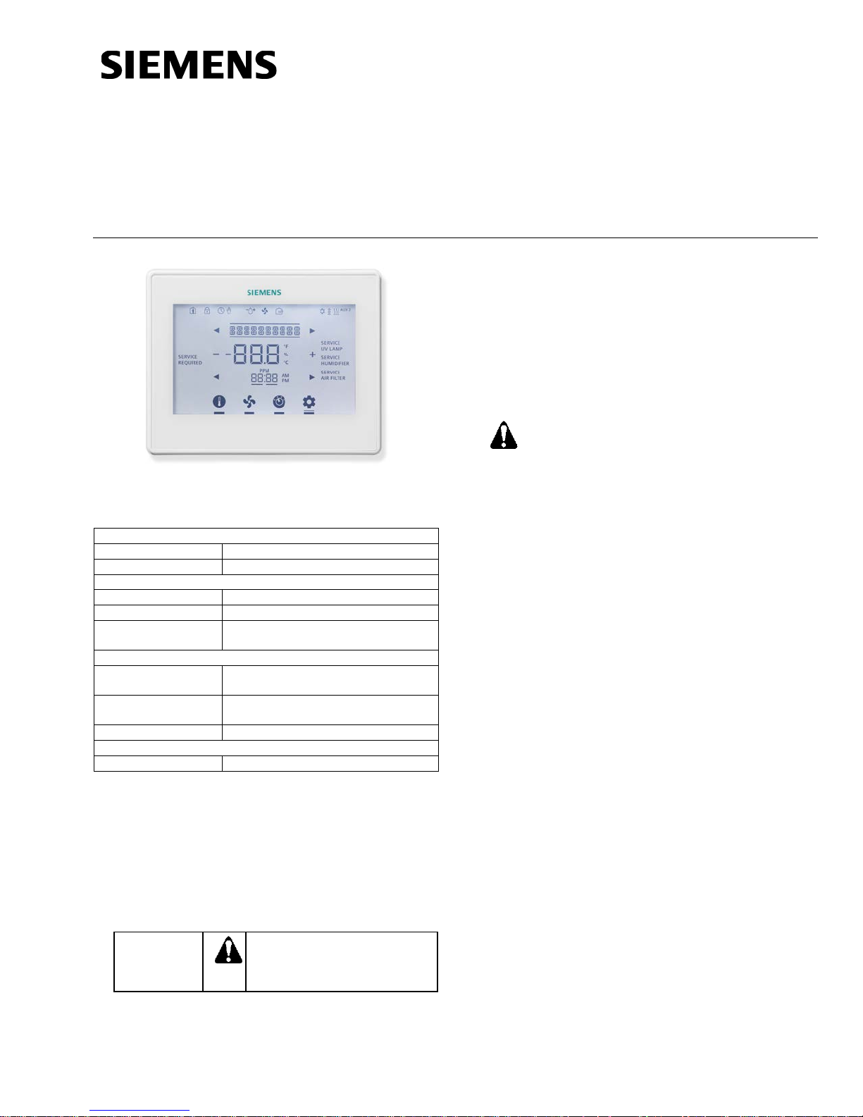
RDY2000 Commercial
System Compatibility
Conventional
Up to 3 Heating/3 Cooling stages
Heat Pumps
Up to 4 Heating/2 Cooling stages
Electrical Characteristics
Power Supply
24 Vac +/-20%, Class 2, 4A max .
Power Usage
4 VA (maximum)
Output Relay
Ratings
Pilot duty, 1A max. per output, 4A
max total
Ambient Limitations
Operating
Temperature
Storage/Shipping
Temperature
Relative Humidity
Up to 95% (non-condensing)
Enclosure
Rating
NEMA 1
CAUTION:
Equipment damage or loss of
specified.
CAUTION:
Document No. 129-905
March 26, 2015
Room Thermostat
Figure 1. RDY2000 Thermostat.
Product Specifications
23°F to 122°F (-5°C to 50°C)
-13°F to 158°F (-25°C to 70°C)
NOTE: The RDY2000 is not battery-powered. It
requires 24 Vac power from the HVAC
equipment at terminals RH/RC and C.
Product Number
RDY2000
Required Tools
• No. 1 Phillips screwdriver
• 1/8” flat-blade screwdriver
• Drill with 1/8" drill bit
Expected Installation Time
15 minutes
The RDY2000 is an advanced controller
designed to be installed by professional
HVAC technicians. Installation by nonqualified personnel may result in degraded
system efficiency, occupant discomfort, or
equipment damage.
Prerequisites
• All work must be performed in accordance
with applicable codes and standards.
• Use 18 gauge thermostat wire for equipment
connections.
• 22 gauge shielded cable is recommended
for remote sensor wiring. Do not exceed 150
feet.
• To replace an existing thermostat, verify if
24 Vac is present between the RH/RC and
C terminals.
• Turn off power to the HVAC equipment
before attempting to remove the existing
thermostat.
• Record wiring connections to existing
thermostat terminals.
• Remove the existing thermostat before
proceeding.
Caution Notations
data may occur if you do not
follow the procedures as
Item Number 129-905, Rev. EA Page 1 of 18
Para accede al documento en Español, escanee el código QR que se encuentra en la parte trasera del termostato.
Installation
1. Install the thermostat base plate.
a. Feed the existing wires through the opening
in the base plate.
b. Secure the base plate to the mounting
surface using supplied hardware.
Page 2
Document No. 129-905
Enables adustment of temperature
cooling setpoint if in Cooling mode.
Enables fan relay to be controlled
to be on continuously (ON).
Enables manual changeover
control functions.
Enables Scheduler, Time/Date, and
and fault messages.
Installation Instructions
March 26, 2015
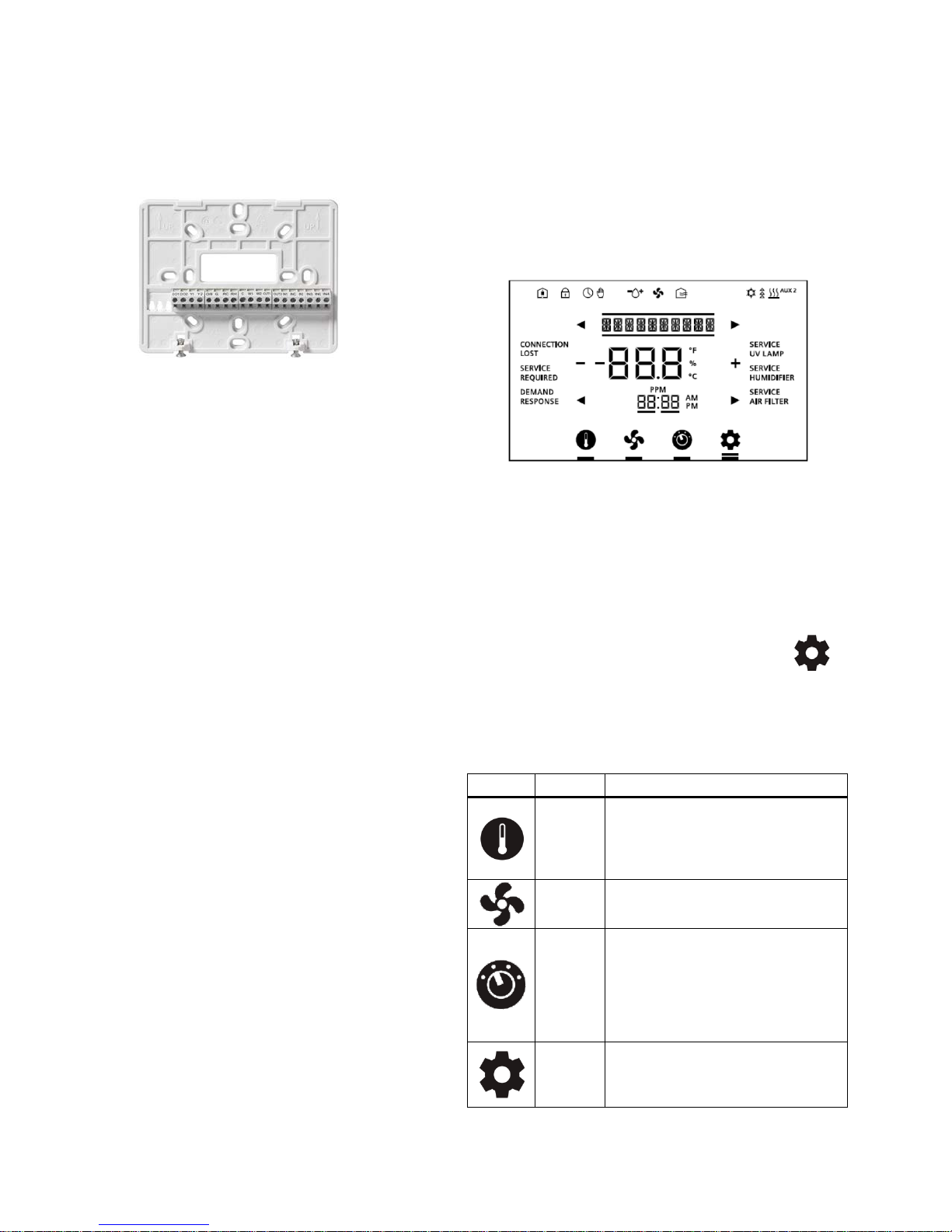
NOTE: Ensure that the UP ar ro ws embossed
on the base plate are pointed upward.
Figure 2. Thermostat Base Plate.
NOTE:
If 24 Vac was verified as being present
at the thermostat wires (see
Prerequisites), sk ip Step 2 and proceed
to Step 3.
2. If 24 Vac is not present at the thermostat:
a. Locate the 24 Vac transformer or 24 Vac on
the terminal strip on the HVAC unit. Attach a
thermostat wire to the 24 Vac source. See
the HVAC equipment schematics to verify
the correct terminals.
b. Attach the other end of the unused wire to
the thermostat RH or RC terminal.
c. Verify that 24 Vac is present between the
RH/RC and C terminals.
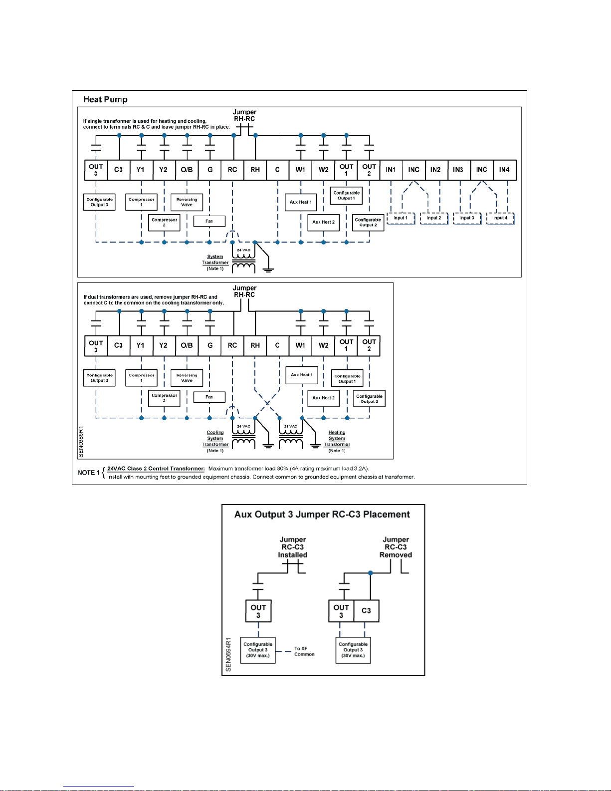
3. Attach the existing wires to the appropriate
terminals on the thermostat base plate. See
Wiring Diagrams, Figure 4 and Figure 5.
Optional: If using Auxiliary Inputs 1 to 4 or
configurable outputs 1 to 3, use setup
parameters P301 to P320 to set functionality.
4. For systems with dual transformers, do the
following; otherwise, proceed to Step 5:
If separate transformers are used for heating
and cooling systems, connect 24 Vac from the
cooling system to RC, and 24 Vac from the
heating system to RH. Remove Jumper RHRC.
Optional: Auxiliary Output 3 can be changed to
a dry (unpowered) contact by removing Jumper
RC-C3 See Wiring Diagrams, Figure 6.
5. Attach thermostat to the base plate by engagi ng
tabs at the top and rotating the thermostat
downward until it is securely seated on the base
plate.
6. Secure the thermostat to the base plate with the
Phillips screws (provided), using the holes at
the bottom of the housing.
The installation is now complete. Restore power,
and continue to Thermostat Setup.
Thermostat Setup
Figure 3. Thermostat Display.
Thermostat Display
Navigation Bar
Only one function can be selected at a time. The
small bar (cursor) below the function icon indicates
that a function is selected. Pressing an icon twice
navigates back to the Main screen.
A double bar cursor below the Settings icon [
indicates that you are in Programming mode.
The navigation bar at the bottom of the display
consists of four function icons.
Table 1. Navigation Bar Icons.
Icon Name Purpose
and humidity (if applicable)
Setpoint
Selector
Settings
Fan
Control
Mode
setpoints. Unit will display heating
setpoint if in Heating mode or
as needed by thermostat (AUTO) or
between Heating and Cooling
mode. AUTO will enable the
thermostat to automatically switch
between heating and cooling mode
as required. OFF will disable all
Installer Set Up configuration. Also
enables access to service reminder
]
Page 2 of 18 Siemens Industry, Inc.
Page 3
Document No. 129-905
Space is occupied,
Sensor.
Unit is running on the
local schedule.
The Scheduler is being
control.
Droplet and (+) indicates
not appear.
Economizer Enable/
Ventilation relay is on.
The system is actively in
cooling mode.
The system is actively in
heating mode.
Each segment
heating or cooling.
Auxiliary heating stage:
2=Stage 2
Installation Instructions
March 26, 2015
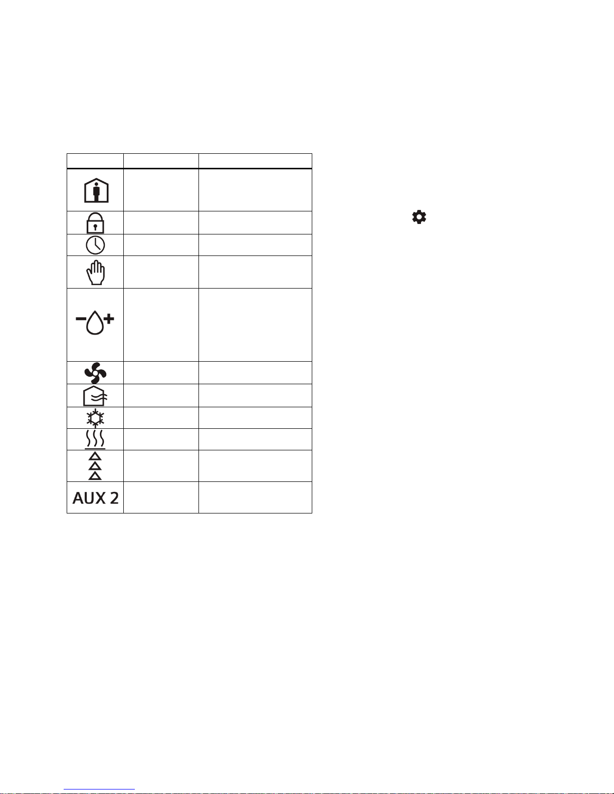
Status Bar
The status bar at the top of the display consists of
11 icons.
Table 2. Status Bar Icons.
Icon Name Meaning
Occupied
Keypad Lock Keypad is locked.
Scheduler
Override
Humidity
Control
Indicator
Fan Fan relay is on.
based on Schedule
and/or Occupancy
overridden by local
humidification relay is on.
Droplet and (-) indicates
dehumidific ation relay is
on. If neither relay is on,
the water droplet does
Service Reminders and Fault Messages
• Service reminders appear at the right side of the
screen:
– SERVICE UV LAMP
– SERVICE HUMIDIFIER
– SERVICE AIR FILTER
They are determined by the timer set in the Installer
Setup Menu, and can be cleared by pressing the
Settings icon [
], and then SERVICE. See
Clearing Service Reminders.
• Active fault messages appear at the left side of
the home screen:
– CONNECTION LOST (Not applicable to this
model)
– DEMAND RESPONSE (Not applicable to
this model)
– SERVICE REQUIRED (See Viewing Fault
Messages)
Fault messages are automatically cleared when the
root cause of the failure is resolved.
Fresh Air
Cool Mode
Heat Mode
Heating/Cooling
Stages
Auxiliary
Heating
represents one stage of
AUX=Stage 1: Aux
Siemens Industry, Inc.
Page 3 of 18
Page 4

Document No. 129-905
Installation Instructions
March 26, 2015
Wiring Diagrams
Figure 4. Wiring Schematic, Conventional System.
Page 4 of 18 Siemens Industry, Inc.
Page 5
Document No. 129-905
Installation Instructions
March 26, 2015
Siemens Industry, Inc.
Figure 5. Wiring Schematic, Heat Pump.
Figure 6. Wiring Schematic, Aux Output 3.
Page 5 of 18
Page 6

Document No. 129-905
Installation Instructions
March 26, 2015
Set-up Wizard
When the unit is powered up for the first time,
WIZARD displays. This tool is used to program the
basic system parameters. Additional parameters can
be accessed directly via the Installer/Ex per t Set-up
menus.
NOTE: The thermostat will not start the control
sequence until the Set-up Wizard is
complete.
1. Press WIZARD to access the menu.
2. Press + or – to change parameter settings, and
then use left and right arrows to select the
additional parameters.
3. After verifying all parameters, press Confirm to
save and complete.
4. INSTALLER displays. If setup is complete,
press the Settings icon [
Wizard. If further setup is needed, continue to
Step 6.
5. Press INSTALLER to access the Installer Menu
and more detailed setup. See Table 3 through
Table 7 for all parameter descriptions.
6. Use the space provided in Table 15 to record
modified parameter settings.
7. Press the Settings icon [
exit setup.
Programming Temperature Setpoints
1. Touch the center of the Home screen to access
the room temperature screen. Use the left []
and right [] arrows adjacent to the text line to
display the room temperature and humidity.
] to exit the Set-up
] when finished to
NOTE: If the screen is not touched for 10
seconds, the unit returns to the Home
screen.
Programming Time and Date
1. Touch the center of the Home screen.
2. Press the Settings icon [
]. SCHEDULER
displays.
3. Use the left [] and right [] arrows to access
the Time menu. Press TIME. Press the two-digit
hour display to change the hour, or press the
two-digit minute display to change the minutes.
Press the left arrow to decrease the value, and
the right arrow to increase the value.
4. Press the Settings icon [
] to save.
5. Use the left [] and right [] arrows to access
the Date menu. Press DATE. Use the arrows to
select the month and year; use +/- to set the
date.
6. Press the Settings icon [
] to save.
Installer Menu
1. Touch the center of the Home screen.
2. Press the Settings icon [
]. SCHEDULER
displays.
3. Press the left arrow [].
4. Press INSTALLER.
5. Using the lower left [] and right [] arrows,
enter the password.
6. Press PASSWORD to accept the password.
2. Touch the Setpoint icon [
] of the screen to
access room temperature and humidity
setpoints.
NOTE: Only the setpoints in the current mode
display and can be modified. For
instance, if the thermostat is in heating
mode, only the heating setpoint
displays and can be modified. If the
thermostat is in AUTO mode, both the
heating and cooling setpoints will be
displayed and can be modified.
3. Use the left [] and right [] arrows to access
the different setpoints, and the + and – icons to
adjust the setpoints.
4. Touch the center of the screen to exit Setpoint
Programming.
Page 6 of 18
Siemens Industry, Inc.
NOTE: The Installer Level d ef ault pass wor d is
00:00
7. Press the Settings icon [
] to accept
changes and return the unit to the Home
screen.
NOTE: If you do not provide input, the thermostat
will automatically exit the Installer menu and
resume normal system control after five
minutes.
Page 7

Document No. 129-905
CAUTION:
Installation Instructions
March 26, 2015
Programming the Schedule
1. Touch the center of the Home screen.
2. Press the Settings icon [
display.
3. Press SCHEDULER.
4. Use the left [] and right [] arrows to select
the day. Press the day to select.
5. Use the + and – icons to set the temperature
setpoints.
6. Use the left [] and right [] arrows to adjust
the start time for each programming period. After
selecting the start time, confirm by touching
above the temperature display before moving to
the next programming period.
7. Depending on the setting on the Scheduler
(Parameter 107 – 108), set the schedule for
each period. See Table 10 through Table 13 for
default schedules.
Resetting the Unit to Factory Defaults
The following steps set ALL parameters to
factory defaults (including passwords), and
restart the Set-up Wizard.
1. Log in as either an Installer or Expert.
2. Press the left [] arrow. RESTORE displays.
3. Press + to change the setting to YES.
4. Press RESTORE.
This resets the unit and restarts the Set-up Wizard.
]. SCHEDULER will
4. Using the lower left [] and right [] arrows,
enter the INSTALLER password.
5. Press PASSWORD to accept the password.
6. Set Parameter 211 (Keypad Lockout) to zero to
disable keypad lockout.
7. Touch the Setpoint icon [
return to the Home screen.
Clearing Service Reminders
The thermostat displays SERVICE REQUIRED and
an associated service reminder if the reminder timer
(Parameters 208 - 210) has timed out. To clear
these, do the following:
1. Touch the center of the Home screen to access
the room temperature screen.
2. Press the Settings icon [
displays.
3. Use the left [] and right [] arrows to select
the service reminder.
4. To clear, touch the + icon and the display
changes from “-----“ to OFF.
5. Counter resets and reminder icons turn off.
Viewing Fault Messages
The thermostat displays SERVICE REQUIRED if a
sensor fails or a service reminder has timed out. To
view these, do the following:
1. Touch the center of the Home screen to access
the room temperature screen.
] of the screen to
] and SERVICE
Maintenance
Locking/Unlocking the Touch Screen
To prevent unauthorized access to thermostat
settings, use Parameter P211 to configure screen
lockouts. The lock icon [
screen is locked. To unlock the keypad, do the
following:
1. Touch the center of the Home screen to access
the room temperature screen.
2. Press the Settings icon [
LOCKED displays.
3. Press and hold the Settings icon [
seconds; PASSWORD displays.
Siemens Industry, Inc.
] indicates that the
] once and
] for 5
2. Press the Settings icon [
displays.
3. Press SERVICE and review faults. Use the left
[] and right [] arrows to see all faults.
NOTE: The fault message is automatically
cleared when the root cause of the
failure is resolved.
] and SERVICE
Page 7 of 18
Page 8

Document No. 129-905
0
3
YES = Fan Relay energized by thermostat
thermostat on call for heat
0 = Disable Scheduler
7 = Schedule each day individually
F
C
NOTE: Changing temperature units will reset all temperature-
related parameters to their default values.
This parameter does
cool only.
This parameter does
heating/cooling cycles.
Y = Auto adjust for Daylight Savings Time
Savings Time
Daylight Savings Time
USA schedule.
Installation Instructions
March 26, 2015
Table 3. 100 Series Parameters*.
Parameter Definition Display Value Range Default Extended Definition Notes
P101 System Type SYS TYPE
P102
P103
P104
P105 Fan Operation HTG FAN
P106
P107
Cooling
Stages
Heating
Stages
Aux Heating
Stages
Reversing
Valve
Scheduler
Days
COOL STGS
HEAT STGS
AUX HT STG
REV VALVE
SCHEDULER
CO
HP
1
2
0
1
2
3
0
1
2
NO
(YES if
P101=HP)
O
B
0
1
2
3
7
CO
YES
O
CO = Conventional System
HP = Heat Pump
2 Sets number of cooling stages.
2 Sets number of heating stages.
Sets number of auxiliary heat stages
0
available for heat pump control.
on call for heat
NO = F an rel ay not energi zed by
O = Energize reversing valve on cooling
B = Energize reversing valve on heating
1 = Schedule all days with same
schedule
2 = One schedule for M-F and another for
2
Sat + Sun
3 = One schedule for M-F, Sat + Sun
scheduled individually
This parameter only
appears if P101 = HP.
If HVAC unit does not
start fan on call for
heat, set P105 to YES.
This parameter only
appears if P101 = HP.
See Table 9 through
Table 13.
P108
P109 Units UNITS
P110 Auto Change AUT O CHNG E
P111
P112
* Included in Set-up Wizard
Program
Periods
Changeover
Deadband
Daylight
Savings
PERIODS
DEADBAND
DAYLT SAVE
2
4
YES
NO
3°F to 9°F
(2.0°C to
5.0°C)
NO
YES
2
F
YES
5°F
(3.0°C)
YES
Sets number of program periods per day:
2 = 2 periods (Day/Night)
4 = 4 periods (Wake/Day/Evng/Night)
Enables auto change between heating and
cooling.
Changeover deadband in degrees F (C)
N = Does not auto adjust for Daylight
This parameter only
appears if P107 > 0.
not appear on systems
that are heat only or
not appear if P110 =
NO.
This parameter forces a
separation between
heating and cooling
setpoints to prevent
short cycling of
adjustment is based on
Page 8 of 18
Siemens Industry, Inc.
Page 9

Document No. 129-905
Heat T emp
Limit
45°F to 95°F
(7.0°C to 35.0°C)
95°F
(35.0°C)
Sets maximum allowable heating set
point.
50°F to 95°F
35.0°C)
Temperature
Offset
-5°F to 5°F
3. 0°C)
Enables adjustment of control temp and display temperature in 1
only.
Number of hours that scheduled
--- = Unlimited
Number of degrees that are allowed
--- = Unlimited
OFF
45°F (7.0°C)
This parameter only appears
- P206 < P207.
This parameter only appears
- P207 > P206.
Number of calendar days until
0 = function disabled.
Number of calendar days until
0 = function disabled.
Number of calendar days until
0 = function disabled.
0 = No Lock out
2 = Total Lock out
12
24
12 = 12-hour format
24 = 24-hour format
Number of seconds that backlight
0 = Always off.
Installation Instructions
March 26, 2015
Table 4. 200 Series Parameters.
Parameter Definition Display Value Range Default Extended Definition Notes
P201
P202
P203
P204
P205
P206
P207
P208
Cool Temp
Limit
Display
Override
Time Limit
Override
Temp Limit
Heat Pump
Compressor
Lock Out
Heat Pump
Auxiliary
Heat Lockout
Service UV
Lamp
HEAT LIMIT
COOL LIMIT
TMP OFFSET
HRS OVR RD 0 t o 96 hours ---
TMP OVR RD
HP COMP LO
HP AUX LO
UV LAMP 0 to 365 days 0
(10.0°C to
(-3.0°C to
1°F to 10°F
(0.5°C to 4.0°C)
15°F (-9.0°C)
20°F (-6.0°C)
25°F (-3.0°C)
30°F (-1.0°C)
35°F (1.0°C)
40°F (4.0°C)
OFF
40°F (4.0°C)
45°F (7.0°C)
50°F (10.0°C)
55°F (13.0°C)
60°F (16.0°C)
50°F
(10.0°C)
0°F
(0°C)
---
OFF
OFF
Does not appear if P103 = 0.
Sets minimum allowable cooling set
point.
degree increments. Applies only to onboard temp sensor. Indoor temp
setpoint can be manually overridden.
0 = No override allowed
above or below scheduled setpoint.
Heat pump compressor will not
operate below this outdoor temp -forcing unit to auxiliary heat. An
outdoor temperature sensor is
required.
NOTE: If P206 ≠ OFF, set P508 = 1°F
(0.5°C).
Heat pump auxiliary heat will not
operate above this outdoor temp. An
outdoor temperature sensor is
required.
SERVICE UV LAMP message
displays.
Does not appear if P102 = 0.
This parameter will not
appear if P107 = 0.
This parameter will not
appear if P107 or P204 = 0.
for the following conditions:
- P101 = HP.
- P104 > 0.
- P105 = YES
- P301, P305, P309,
or P313=5
for the following conditions:
- P101 = HP.
- P104 > 0.
- P301, P305, P309,
or P313 = 5
P209
P210
P211
P212 Cl ock Format CLOCK
P213 Backlight LIGHT 0 to 99 seconds 15
Service
Humidifier
Service Air
Keypad
Lockout
Filter
HMDFR
SRVC
FLTR SRVC 0 to 365 days 0
KEY LOCK
0 to 365 days 0
0 = NONE
1 = PARTIAL
2 = FULL
Siemens Industry, Inc.
0
12
SERVICE HUMIDIFIER message
displays.
SERVICE AIR FILTER message
displays.
1 = Partial Lockout (only temp setpoint
can be adjusted)
stays on after screen is touched.
Keypad lock icon [ ]
displays if P211 > 0.
Page 9 of 18
Page 10

Document No. 129-905
0
9
0 = Not Used
9 = Fault
- Selections for inputs 1-4
RDY2000.
Temperature
Input 1 Type
0
1
0 = Type 2 Thermistor
1 = 0-10V
Only appears if
P301=1/2/3/4/5.
-58°F to
50.0°C)
P303 value
(120.0°C)
Calibrates thermostat to high end of
example, 10V = 250°F [120.0°C])
0
9
0 = Not Used
9 = Fault
- Selections for Inputs 1-4
RDY2000.
Temperature
Input 2 Type
0
1
0 = Type 2 Thermistor
1 = 0 to 10V
Only appears if P305 =
1/2/3/4/5.
-58°F to
50.0°C)
P307 value
(120.0°C)
Calibrates thermostat to high end of
example, 10V = 250°F).
0
9
0 = Not Used
9 = Fault
- Selections for Inputs 1-4
RDY2000.
Only appears if P309 =
Installation Instructions
March 26, 2015
Table 5. 300 Series Parameters.
Parameter Definition Display
P301
P302
P303
P304
P305
Configurable
Input 1 (IN1)
Temperature
Input 1 Low
Temperature
Input 1 High
Configurable
Input 2 (IN2)
INPUT 1
TMP I N 1
TMP 1 LO
TMP 1 HI
INPUT 2
Value
Range
1
2
3
4
5
6
7
8
120°F **
(-50.0°C to
** to 250°F
1
2
3
4
5
6
7
8
Default Extended Definition Notes
0
0
0°F
(-18.0°C)
120°F
(50.0°C)
0
1 = Indoor Temperature (Remote)
2 = Indoor Temperature (Average)
3 = Supply Temp
4 = Return Temp
5 = Outdoor Temp
6 = Humidity (0-10V)
7 = CO2 (0-10V)
8 = Occupancy (DI)
Calibrates thermostat to low end of temp
sensor signal (for example, 0V = -40°F
[4.4°C])
temp sensor signal at 10 volts (for
1 = Indoor Temperature (Remote)
2 = Indoor Temperature (Average)
3 = Supply Temp
4 = Return Temp
5 = Outdoor Temp
6 = Humidity (0-10V)
7 = CO2 (0-10V)
8 = Occupancy (DI)
cannot be duplicated.
- If set to 9 (fault), a DI here
causes SERVICE
REQUIRED segment to
activate.
- See Table 14
optional sensors
approved for use with the
- Only appears if P302=1
** P303<P304.
- Only appears if P302=1.
** P304>303.
cannot be duplicated.
- If set to 9 (fault), a DI
causes SERVIC E
REQUIRED segment to
activate
- See Table 14
optional sensors
approved for use with the
for a list of
for a list of
P306
P307
P308
P309
P310
Temperature
Input 2 Low
Temperature
Input 2 High
Configurable
Input 3 (IN3)
Temperature
Input 3 Type
TMP IN 2
TMP 2 LO
TMP 2 HI
INPUT 3
TMP I N 3
120°F **
(-50.0°C to
** to 250°F
1
2
3
4
5
6
7
8
0
1
0
0°F
(-18.0°C)
120°F
(50.0°C)
0
0
Calibrates thermostat to low end of temp
sensor signal (for example, 0V = -40°F)
temp sensor signal at 10 volts (for
1 = Indoor Temperature (Remote)
2 = Indoor Temperature (Average)
3 = Supply Temp
4 = Return Temp
5 = Outdoor Temp
6 = Humidity (0 to 10V)
7 = CO2 (0 to 10V)
8 = Occupancy (DI)
0 = Type 2 Thermistor
1 = 0-10V
- Only appears if P306 = 1.
** P307 < P308
- Only appears if P306 = 1.
** P308 > P307.
cannot be duplicated.
- If se t to 9 (fault), a DI
here causes SERVICE
REQUIRED segment to
activate.
- See Table 14
optional sensors
approved for use with the
1/2/3/4/5.
for a list of
Page 10 of 18 Siemens Industry, Inc.
Page 11

-58°F to
50.0°C)
P311 value
(120.0°C)
Calibrates thermostat to high end of
example, 10V = 250°F).
0
9
0 = Not Used
9 = Fault
- Selections for Inputs 1-4
RDY2000.
Temperature
Input 4 Type
0
1
0 = Type 2 Thermistor
1 = 0 to 10V
Only appears
P313=1/2/3/4/5.
-58°F to
50.0°C)
P315 value
(120.0°C)
Calibrates thermostat to high end of
example, 10V = 250°F [121.1°C]).
- Selections for Outputs 1-3
as Stage 3 cooling.
0
5
0 = Not Used
5 = Economizer Enable
0
5
0 = Not Used
5 = Economizer Enable
Yes = Humidification/dehumidification
energized.
Parameter Definition Display
Value
Range
Document No. 129-905
Installation Instructions
March 26, 2015
Default Extended Definition Notes
P311
P312
P313
P314
P315
P316
P317
Temperature
Input 3 Low
Temperature
Input 3 High
Configurable
Input 4 (IN4)
Temperature
Input 4 Low
Temperature
Input 4 High
Aux Output 1
(OUT1)
TMP 3 LO
TMP 3 HI
INPUT 4
TMP I N 4
TMP 4 LO
TMP 4 HI
AUX OUT 1
120°F **
(-50.0°C to
** to 250°F
1
2
3
4
5
6
7
8
120°F **
(-50.0°C to
** to 250°F
0
1
2
3
4
5
0°F
(-18.0°C)
120°F
(50.0°C)
0
0
0°F
(-18.0°C)
120°F
(50.0°C)
0
Calibrates thermostat to low end of temp
sensor signal (Example: 0V = -40°F).
temp sensor signal at 10 volts (for
1 = Indoor Temperature (Remote)
2 = Indoor Temperature (Average)
3 = Supply Temp
4 = Return Temp
5 = Outdoor Temp
6 = Humidity (0 to 10V)
7 = CO2 (0 to 10V)
8 = Occupancy (DI)
Calibrates thermostat to low end of temp
sensor signal (for example, 0V = -40°F
[4.4°C]).
temp sensor signal at 10 volts (for
0 = Not Used
1 = Humidification
2 = Dehumidification
3 = Occupied
4 = Air Quality
5 = Economizer Enable
- Only appears if P310 = 1.
** P311 < P312.
- Only appears if P310 = 1.
** P312 < P311.
cannot be duplicated.
- If set to 9 (fault), a DI here
causes SERVIC E
REQUIRED segment to
activate.
- See Table 14
optional sensors
approved for use with the
- Only appears if P314 = 1.
** P315 < P316.
Only appears if P314=1.
** P316>P315.
cannot be duplicated.
- Air Quality not an option
unless P301, P305, P309,
or P313 = 7.
- If system is conventional
with 3H +3C, AO1 is fixed
for a list of
P318
P319
P320
Aux Output 2
(OUT2)
Aux Output 3
(OUT3 & C3)
Independent
Humidity
Control
AUX OUT 2
AUX OUT 3
IND HMDTY
1
2
3
4
1
2
3
4
Yes
No
0
0
No
1 = Humidification
2 = Dehumidification
3 = Occupied
4 = Air Quality
1 = Humidification
2 = Dehumidification
3 = Occupied
4 = Air Quality
relays can be energized
independent of heating/cooling
relays.
No = Humidification/dehumidification
relays are only energized if
heating or cooling relay is
-- Selections for Outputs 1-3
cannot be duplicated.
- Air Quality is not an option
unless P301, P305, P309,
or P313 = 7.
- Selections for Outputs 1-3
cannot be duplicated.
- Air Quality is not an option
unless P301, P305, P309,
or P313 = 7.
Select YES to activate
humidity control systems
regardless of whether there
is a need for heating or
cooling.
Siemens Industry, Inc.
Page 11 of 18
Page 12

Document No. 129-905
Value
Allows HVAC unit number to be
displayed on thermostat home screen.
For optimum human
parts per million.
Pre-Occupancy Purge will
without a schedule.
Occupancy
Run Timer
Minimum run time to remain in
from Occupancy Sensor.
Fan relay will be continuously energized
Sensor.
Only shown if a schedule is
Sensor.
Installer
Password
00:00 to
49.99
NOTE: If Installer Password is changed, a new password should be
recorded for future reference.
Firmware
Revision
Installation Instructions
March 26, 2015
Table 6. 400 Series Parameters.
Parameter Definition Display
P401 Unit Number UNIT NMB R 1 to 999 ---
P402 CO2 Setpoint CO2 SET PT
P403
P404
P405
P407
P701
Pre-
Occupancy
Purge
Sensor Min
Semi-
Continuous
Fan
PRE OC PRG
OCC MRT
CONT FAN
INSTALL PW
FIRMWARE X.X N/A Read Only
Range
500 to
2000
PPM
0
1
2
3
hours
3 to 60
minutes
No
Yes
Expert Level Menus
1. Touch the center of the Home screen.
2. Press the Settings icon [
]. SCHEDULER
displays.
Default Extended Definition Notes
800
0
30
NO
00:00
If CO2 level, as measured by an
external sensor exceeds setpoint, the
Ventilation sequence is initiated.
0 = Disabled
1 = 1 Hour
2 = 2 Hours
3 = 3 Hours
Occupied mode upon receipt of signal
when space is occupied, as determined
by schedule or external Occupancy
performance, CO2 levels
should be kept below 1000
energize the Economizer
Enable and Fan relays prior
to the start of the first
scheduled occupancy period.
Not applicable to systems
Only shown if an input is set
to Occupancy Sensor.
present or if an input is
configured for Occupancy
Recovering a Lost Password
If either of the default passwords is changed, the new
password(s) should be recorded and maintained for
future reference. If the records are misplaced, the
following procedure can be used to set new passwords:
3. Press the left [] arrow.
4. Press INSTALLER.
5. Using the lower left [] and right [] arrows,
enter the password.
6. Press PASSWORD to accept the password and
return the unit to the Setup Menu.
NOTE: The Expert Le ve l default password is
99:99.
7. See Table 3 through Table 8 and Wiring
Diagrams for additional information.
8. Press the Settings icon [
and return the unit to the Home screen.
] to accept changes
1. Cycle power to the thermostat. This can be done
by loosening the securing screws on the bottom
of the housing and momentarily separating the
thermostat from the base plate.
2. Within 50 seconds of restoring power, navigate
to the Installer Set-up screen and enter 98:21 as
the passcode.
3. The thermostat will go directly to the Expert
Level password screen. A new Expert Level
password can now be set.
4. After setting a new Expert Level password, the
thermostat will return to the Home screen.
5. The new Expert Level password can be used to
enter the full Expert Level set-up menu where
both the Expert Level and Installer Level
passwords can now be set to new values.
Page 12 of 18 Siemens Industry, Inc.
Page 13

Document No. 129-905
Time delay before next stage of cooling will be
activated.
1°F (0.5°C) to
10°F (5.0°C)
1°F
(0.5°C)
Degrees above cooling deadband before Stage
Delay timer is initiated.
Delay in minutes before system will automatically
switch from heating to cooling (or vice versa).
The deadband is divided equally above and below
deadband.
Time delay before next stage of heating will be
activated.
Conv. = 1°F
(1.0°C)
Conv = 3
HP = 10
The deadband is divided equally above and below
deadband.
Installation Instructions
March 26, 2015
Table 7. 500 Series Expert Settings Parameters.
(Only available if logged in as an Expert.)
NOTE: P500 Series parameters are factory-set for optimum system performance. Changing these settings may degrade
efficiency and/or compromise occupant comfort.
Parameter Definition Display Value Range Default Extended Definition
P501 Stage Delay - Cooling STG DLY CL 1 to 10 minutes 2
P502 Stage Differential - Cooling STG DIF CL
P503 Cooling Minimum Off Time M O T CL 1 to 10 minutes 3 Minim um time between compressor st arts.
P504 Cooling Minimum On Time M R T CL 1 to 10 minutes 5 Mini mum run time for any stage of cooling.
P505 Changeover Delay C-O DLY 1 to 60 3
P506 Cooling Deadband CL DEADBND
P507 Stage Delay - Heating ST G DLY HT 1 to 10 minutes 2
P508 Stage Differential - Heating STG DIF HT
P509 Heating Minimum Off Time M O T HT 1 to 10 minutes 5 Minimum time between heating starts.
P510 Heating Minimum On Time M R T HT 1 to 10 minutes
P511 Heating Deadband HT DEADBND
1°F (0.5°C) to
5°F (4.0°C)
1°F (0.5°C) to
5°F (5.0°C)
1°F (0.5°C) to
5°F (4.0°C)
1°F
(0.5°C)
HP = 2°F
1°F
(0.5°C)
setpoint. Cooling will begin when temperature
exceeds upper point of deadband and ceases
when temperature falls below lower point of
Degrees below heating deadband before Stage
Delay timer is initiated.
NOTE: If P206 ≠ OFF, set P508 = 1°F (0.5°C)
Minimum run time for any stage of heating.
setpoint. Heating will begin when temperature
falls below lower point of deadband and ceases
when temperature rises above upper port of
Siemens Industry, Inc.
Page 13 of 18
Page 14

Document No. 129-905
CAUTION:
Installation Instructions
March 26, 2015
Table 8. 900 Series Expert Settings Parameters.
(Only available if logged in as an Expert.)
P900 Series parameters are used by professional HVAC technicians during the system commissioning
process. Interlocks and time delays are defeated while using P900 parameters. Use of these parameters by
non-qualified personnel may result in equipment damage.
Parameter Definition Display Value Range Default Extended Definition
P901 Test Compressor 1 Y1 TEST
P902 Test Compressor 2 Y2 TEST
P903 Test Reversing Valve O/B T EST
P904 Test Fan G TEST
P905 Tes t Heat St g 1 W1 TEST
P906 Tes t Heat St g 2 W2 TEST
P907 Test Output 1 OUT1 TST
P908 Test Output 2 OUT2 TST
P909 Test Output 3 OUT3 TST
P911 Expert Password XP RT PW 50:00 to 99:99 99:99
ON
OFF
ON
OFF
ON
OFF
ON
OFF
ON
OFF
ON
OFF
ON
OFF
ON
OFF
ON
OFF
OFF
OFF
OFF
OFF
OFF
OFF
OFF
OFF
OFF
OFF = Relay not energized
ON = Relay energized
OFF = Relay not energized
ON = Relay energized
OFF = Relay not energized
ON = Relay energized
OFF = Relay not energized
ON = Relay energized
OFF = Relay not energized
ON = Relay energized
OFF = Relay not energized
ON = Relay energized
OFF = Relay not energized
ON = Relay energized
OFF = Relay not energized
ON = Relay energized
OFF = Relay not energized
ON = Relay energized
Auxiliary Sequences
The RDY2000 primary sequences are designed to
control single and multi-stage heating/cooling systems to
maintain a user-selected temperature setpoint.
The following auxiliary sequences are available to
optimize occupant comfort and system efficiency:
Humidification
Parameters
• P317/ P318/P319: One of these must be set to 1
• P320: NO (default) = Humidification will only
occur if there is a call for heating. YES =
Humidification relay will be energ i zed
independently of heating and cooling relays.
Page 14 of 18 Siemens Industry, Inc.
• Humidity Setpoint: User adjustable to desired
level in humidification mode.
Sensors: Onboard humidity sensor or optional remote
humidity sensor.
The humidification relay will energize when measured
humidity drops approximately 4% below setpoint and will
de-energize when measured humidity reaches setpoint.
Deadbands and proof timers are in force to prevent short
cycling.
Page 15

Document No. 129-905
Installation Instructions
March 26, 2015
Dehumidification
Parameters
• P317/ P318/P319: One of these must be set to 2
• P320: NO (default) = Dehumidification will only
occur if there is a call for cooling. YES =
Dehumidification relay will be energized
independently of heating and cooling relays.
• Dehumidity Setpoint: User adjustable to desired
level in dehumidification mode.
Sensors: Onboard humidity sensor or optional remote
humidity sensor.
The dehumidification relay will energize when measured
humidity rises approximately 4% above setpoint and will
de-energize when measured humidity reaches setpoint.
Deadbands and proof timers are in force to prevent short
cycling
Economizer Enable
Parameters
• P317/P318/P319: One of these must be set to 5.
• P301/P305/P309/P313: One of these must be
set to 8 if the optional occupancy sensor is used.
Sensors: None required, however an optional occupancy
sensor can be used instead of, or in conjunction with the
scheduler to determine occupancy.
The Economizer Enable relay will be energized
whenever a cooling relay is energized or the space is
occupied. The thermostat will use the scheduled
setpoints to predict when s pace is occ upie d. An opt ion al
occupancy sensor can also be used for definitive proof
of occupancy.
An output configured for Occupancy Notification can also
be used for Economizer Enable.
Pre-Purge
Parameters
• P317/P318/P319: One of these must be set to 5.
• P403
Sensors: None required.
To enable the economizer and energize the fan relay
prior to scheduled occupancy, set P403 to the number of
hours before scheduled occupancy for pre-purge to
begin. This function requires a schedule to be
configured.
Occupancy Notification
Parameters
• P301/P305/P309/P313: If the optional occupancy
sensor is used, one of these must be set to 8.
• P317/P318/P319: To signal an external device that
the space is occupied, one of these must be set to 3
• P404: If the optional occupancy sensor is used,
P404 can be used to set a minimum run timer for
any actions that are activated by occupancy, such
as Economizer Enable, control to occupied
temperature setpoints, and so on. Note that many
occupancy sensors also have onboard proof timers.
There are two primary methods by which the thermostat
can assume the space is occupied.
1. In Cooling mode, it will assume that scheduled
periods with lower setpoint(s) indicate
occupancy. In Heating mode, it will assume
occupancy during periods of higher setpoints.
2. During periods in which the schedule indicates
the space is unoccupied, any human interaction
with the thermostat (for example, setpoint
adjustment) will put the therm ostat into
Occupied mode.
The optional occupancy sensor can be used in
conjunction with the schedule. The thermostat will follow
the assumptions above, but an input from the occupancy
sensor during a scheduled unoccupied period will put the
thermostat in the Occupied mode for the duration of the
timer set in P404.
To utilize the Occupancy functions, the thermos tat must
have an active schedule.
Air Quality Management
Parameters
• P301/P305/P309/P313: One of these must be
set to 7.
• P317/P318/P319: One of these must be set to 4.
• P402: CO2 Setpoint
Sensors: Optional CO2 Sensor
• If measured CO2 exceeds setpoint by 200 PPM,
the Air Quality output and fan relays will be
energized. The minimum run time is 5 minutes.
• When measured CO2 falls below setpoint and
appropriate minimum run time has been met, the
Air Quality output relay will be de-energ i zed an d
the fan relay shall revert to normal operation.
Siemens Industry, Inc.
Page 15 of 18
Page 16

Document No. 129-905
Per Day
Per Day
Phase
Day
Night
Wake
Day
Evng
Night
Setpoint
Heat, °F
70
62
70
62
70
62
Setpoint
Cool,°F
75
82
75
78
75
82
Time
6:00
AM
10:00
PM
6:00
AM
11:00
AM
1:00
PM
10:00
PM
NOTE: 2 Periods per Day
Phase
Day
Night
Day
Night
Wake
Day
Evng
Night
Wake
Day
Evng
Night
Setpoint
Heat, °F
70
62
70
62
70
68
70
62
70
68
70
62
Setpoint
Cool, °F
75
82
75
82
75
78
75
82
75
78
75
82
Time
6:00
AM
10:00
PM
8:00
AM
10:00
PM
6:00
AM
11:00
AM
1:00
PM
10:00
PM
8:00
AM
11:00
AM
1:00
PM
10:00
PM
Phase
Day
Night
Day
Night
Day
Night
Setpoint
Heat, °F
70
62
70
62
70
62
Setpoint
Cool, °F
75
82
75
82
75
82
Time
6:00
AM
10:00
PM
8:00
AM
10:00
PM
8:00
AM
10:00
PM
Phase
Wake
Day
Evng
Night
Wake
Day
Evng
Night
Wake
Day
Evng
Night
Setpoint
Heat
70
68
70
62
70
68
70
62
70
68
70
62
Setpoint
Cool
75
78
75
82
75
78
75
82
75
78
75
82
Time
6:00
AM
11:00
AM
1:00
PM
10:00
PM
8:00
AM
11:00
AM
1:00
PM
10:00
PM
8:00
AM
11:00
AM
1:00
PM
10:00
PM
Installation Instructions
March 26, 2015
Table 9. Single Schedule.
Day
2 Periods
4 Periods
NOTE: Daily Schedule – 2 periods per day: Parameter 107 = 1; Parameter 108 = 2
Daily Schedule – 4 periods per day: Parameter 107 = 1; Parameter 108 = 4; Parameter 109 = F
Table 10. Work Week Schedule with Weekend.
(Factory Default)
Parameter 107 = 2;
Day
Parameter 108 = 2;
Parameter 109 = F
Work Week
(Monday-
Friday)
Weekend
(Saturday-
Sunday)
NOTE: 4 Periods per Day
Parameter 107 = 2; Parameter 108 = 4; Parameter 109 = F
Work Week
(Monday-Friday)
Weekend
(Saturday-Sunday)
Table 11. Work Week Schedule with Sep arat e Week end D ays - 2 Periods per Day.
Day Work Week
Saturday
Sunday
(Monday-
Friday)
NOTE: Individual Days, periods per day: Parameter 107 = 3; Parameter 108 = 2; Parameter 109 = F
Table 12. Work Week Schedule with Separate Weekend Days – 4 Periods Per Day.
Work Week (Monday-Friday) Saturday Sunday
NOTE: Parameter 107 = 3; Parameter 108 = 4; Parameter 109 = F
Page 16 of 18 Siemens Industry, Inc.
Page 17

Document No. 129-905
Siemens Indus try, Inc.
+1-847-215-1000
Your feedback is important to us. If you have
Document No. 129-905
Phase
Day
Night
Wake
Day
Evng
Night
Setpoint Heat
70
62
70
62
70
62
Setpoint Cool
75
82
75
78
75
82
Time
6:00 AM
10:00 PM
6:00 AM
11:00 AM
1:00 PM
10:00 PM
Siemens Part
Number
Installation Instructions
March 26, 2015
Table 13. Individual Days (Monday – Sunday).
Day 2 Periods
Per Day
4 Periods
Per Day
NOTE: Daily Schedule – 2 periods per day: Parameter 107 = 7; Parameter 108 = 2; Parameter 109 = F
Daily Schedule – 4 periods per day: Parameter 107 = 7; Parameter 108 = 4; Parameter 109 = F
Table 14. Suggested Sensors for Use with RDY2000.
Description Signal Format
QAA2330.EWNN
QFA33SS.EWNN
QAM2030.010
QFM2160U
QPA2000 Wall-Mounted CO2 Sensor 0-10V
QPA2062 Wall-Mounted Temperature + Humidity + CO2 Sensor 0-10V
QPM2162
QAC2030
QAD2030
Remote Wall-Mounted Sensor – Temperature Only 10K Ohm, Type II NTC
Remote Wall-Mounted Temperature and Humidity Sensor 0-10V
Duct-Mounted Temperature Sensor 10K Ohm, Type II NTC
Duct-Mounted Temperature & Humidity Sensor 0-10V
Duct-Mounted Temperature + Humidity + CO2 Sensor 0-10V
Outdoor Air Temperature Sensor 10K Ohm, Type II NTC
Surface-Mount Pipe Temperature Sensor 10K Ohm, Type II NTC
Federal Communications Commission Notice
This equipment has been tested and found to comply with the limits for a Class B digital device, pursuant to Part 15 of the FCC rules. These limits are
designed to provide reasonable protection against harmful interference in a residential installation. This equipment generat es, uses, and can radiate
radio frequency energy and, if not installed and used in accordance with the instructions, may cause harmful interference to radio communicat i ons.
However, there is no guarantee that interference will occur in a particular installation. If this equipment does cause harmful interference to radio or
television reception, which can be determined by turning the equipment off and on, the user is encouraged to try to correct the interference by one or
more of the following measures:
--Reorient or relocate the receiving antenna.
--Increase the separation between the equipment and the receiver.
--Connect the equipment into an outlet on a circuit different from that to which the receiver is connected.
--Consult the dealer or an experienced radio/TV technician for help.
Modifications
This device complies with Part 15 of the FCC rules and IC rules. Changes or modifications not expressly approved by Siemens Industry Inc. could void
the user’s authority to operate the equipment.
Industry Canada
This Class B digital apparatus meets all requirements of the Canadian Interference-Causing Equipment Regulations.
Cet appareil numérique de la classe B respecte toutes les exigences du Règlement sur le matériel brouilleur du Canada.
CAN ICES-3 (B)/NMB-3 (B)
Limited Warranty
Siemens Product Guard Warranty warrants the purchased from it or its authorized reseller to be free from defects in material and workmanship under
normal use during the two-year period commencing on the date of purchase. The written proof of purchase is required for such warranty period to apply.
The software included in this Siemens product is licensed for use subject to the Siemens end-user license agreement (“EULA”) posted at
www.usa.siemens.com/btcpseula (Siemens’ EULA web site) for this software identifi ed by product model or part number on the Siemens EULA web site.
Information in this publication is based on current specifications. The company reserves the right to make changes in specifications and models as
design improvements are introduced. Other product or company names mentioned herein may be the trademarks of their respective owners. © 2015
Siemens Industry, Inc.
Building Technologies Division
1000 Deerfield Parkway
Buffalo Grove, IL 60089-4513
USA
comments about this document, please send them
to SBT_technical.editor.us.sbt@siemens.com
Printed in the USA
Page 17 of 18
Page 18

Parameter
Definition
Default
Field Value
P101
System Type
CO
P102
Cooling Stages
2
P103
Heating Stages
2
P104
Aux Heating Stages
0
P105
Fan Operation
NO
P106
Reversing Valve
O
P107
Scheduler Days
2
P108
Program Periods
2
P110
Auto Change
YES
P111
Changeover Deadband
5°F (2.5°C)
P112
Daylight Savings
YES
P201
Heat Temp Limit
95°F (35.0°C)
P202
Cool Temp Limit
50°F (10.0°C)
P203
Temperature Display Offset
0°F (0°C)
P204
Override Time Limit
---
P205
Override Temp Limit
---
P206
Heat Pump Compressor Lock Out
OFF
P207
Heat Pump Auxiliary Heat Lockout
OFF
P208
Service UV Lamp
0
P209
Service Humidifier
0
P210
Service Air Filter
0
P211
Keypad Lockout
0
P213
Backlight
15
P301
Configurable Input 1 (IN1)
0
P302
Temperature Input 1 Type
0
P303
Temperature Input 1 Low
0°F (-18.0°C)
P304
Temperature Input 1 High
120°F (50°C)
P305
Configurable Input 2 (IN2)
0
P306
Temperature Input 2 Type
0
P307
Temperature Input 2 Low
0°F (-18.0°C)
P308
Temperature Input 2 High
120°F (50.0°C)
P309
Configurable Input 3 (IN3)
0
P310
Temperature Input 3 Type
0
P311
Temperature Input 3 Low
0°F (-18.0°C)
P312
Temperature Input 3 High
120°F (50.0°C)
P313
Configurable Input 4 (IN4)
0
P314
Temperature Input 4 Type
0
P315
Temperature Input 4 Low
0°F (-18.0°C)
P316
Temperature Input 4 High
120°F (50.0°C)
P317
Aux Output 1 (OUT1)
0
P318
Aux Output 2 (OUT2)
0
P319
Aux Output 3 (OUT3 & C3)
0
P320
Independent Humidity Control
No
P401
Unit Number
---
P402
CO2 Setpoint
800
P403
Pre-Occupancy Purge
0
P404
Occupancy Sensor Min Run Timer
30
P405
Semi-Cont i nuous Fan
NO
P407
Installer Password
0000
P701
Firmware Revision
N/A
P501
Stage Delay - Cooling
2
P502
Stage Differential - Cooling
1°F (0.5°C)
P503
Cooling Minimum Off Time
5
P504
Cooling Minimum On Time
3
P505
Changeover Delay
10
P506
Cooling Deadband
1°F
P507
Stage Delay - Heating
2
P508
Stage Differential - Heating
Conv. = 1°F (0.5°C); HP = 2°F (1°C)
P509
Heating Minimum Off Time
5
P510
Heating Minimum On Time
5 (10 if heat pump)
P511
Heating Deadband
1°F (0.5°C)
P911
Expert Password
99:99
Table 15. Record Field Settings.
Page 18 of 18 Siemens Industry, Inc.
 Loading...