

Page 1
Installation Instructions
RDU… and RDX42.22U Room
Document No. 129-491
October 6, 2009
Temperature Controllers
Product Description
The RDU Series and RDX42.22U Room
Temperature Controller with LCD are designed for
heating and cooling systems.
Product Numbers
RDU20U Floating output, auto changeover
RDU50U Modulating output, auto changeover
RDU50.2U Modulating output, manual changeover
RDX42.22U On/off output, manual changeover
Required Tools
• Small, flat-blade screwdriver
• Wire strippers
• Electric drill
Expected Installation Time
30 minutes
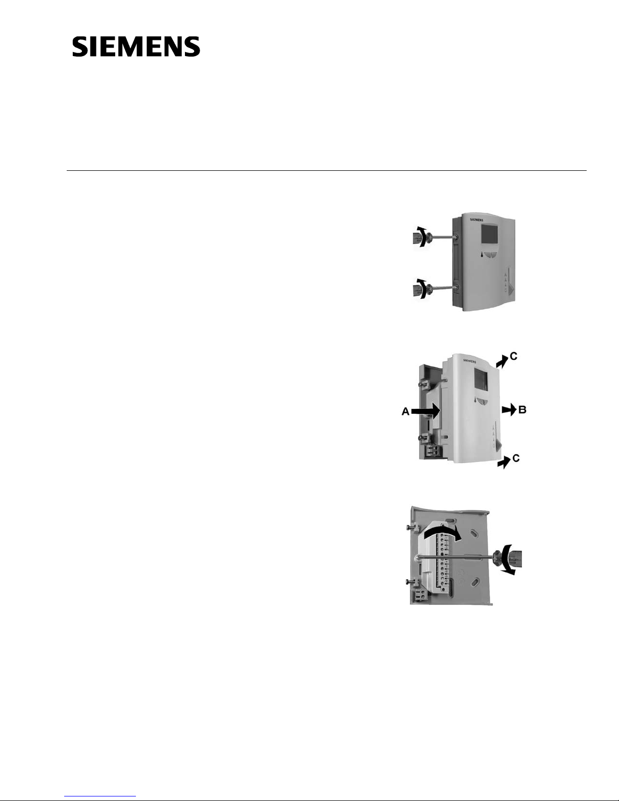
Installation
Step 1. Loosen Retaining Screws.
Accessories:
• 141-570 Lockable Thermostat Guard
• ARG70 Wall Plate Adapter
• QAH11.1 Remote/Chan geover Sensor
Item Number 129-491, Rev. BA Page 1 of 7
Step 2. Remove Controller Housing.
Step 3. Remove Screw and Open Terminal
Cover. Remove Installation Hardware.
Page 2
Document No. 129-491
Installation Instructions
October 6, 2009
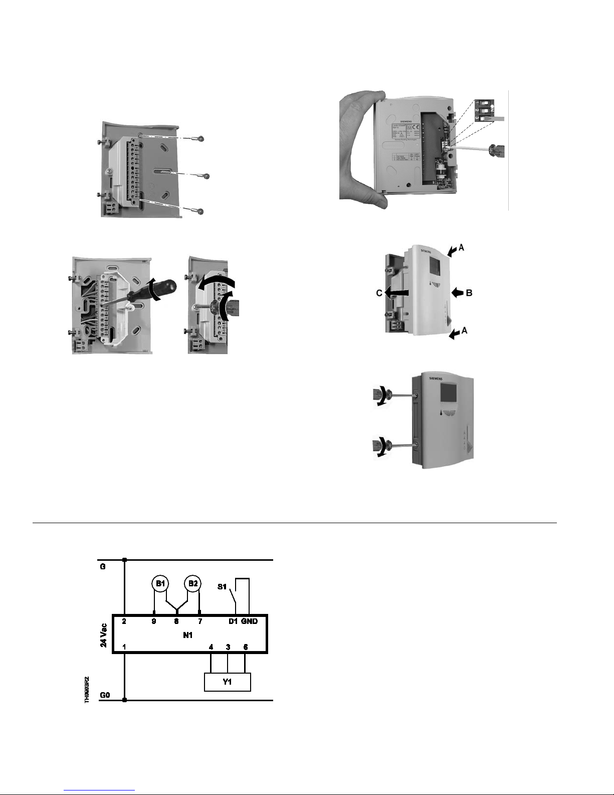
Installation, Continued
Step 4. Mount Base Plate to Wall.
Step 5. Terminate Wires (See Wiring Diagrams),
Close Cover Terminal Cover and Replace Screw.
Step 6. Set DIP Switches.
Step 7. Replace Controller Housing.
Step 8. Tighten Retaining Screws.
Wiring Diagrams
Figure 1. RDU20U.
Page 2 of 7 Siemens Industry, Inc.
The installation is now complete.
1 Operating voltage, 24 Vac negati ve
2 Operating voltage, 24 Vac positiv e
3 Operating voltage, 24 Vac positiv e
4 Control signal, opening, 24 Vac
6 Control signal, closing, 24 Vac
7 Changeover, heat/cool input
8 Measuring neutral (sensors)
9 Remote temperature sensor
D1, Signal input for potential-free operating mode
GND changeover
S1 Time clock or switch
Y1 Damper or valve actuator
Page 3
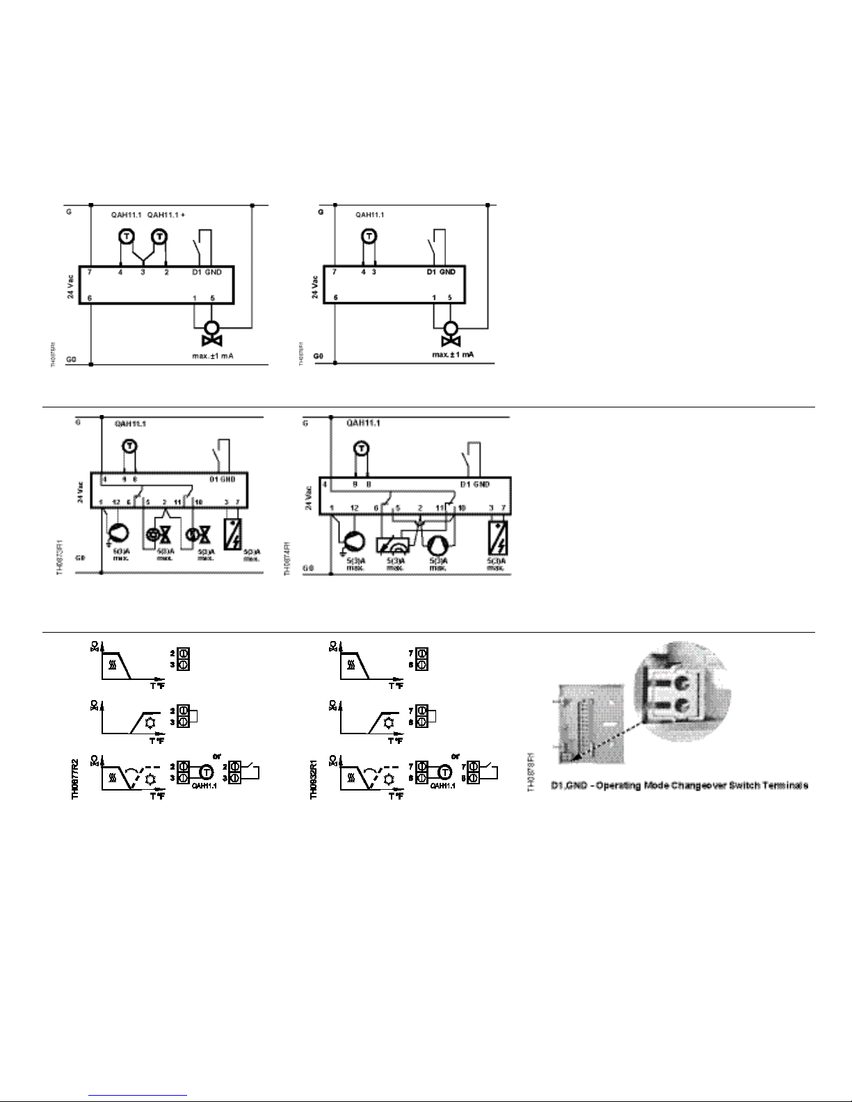
Wiring Diagrams, Continued
D1, Signal input for potential-
Figure 2. RDU50U
Figure 4. RDX42.22U
Four-pipe System Wiring.
Figure 3. RDU50.2U
Figure 5. RDX42.22U
Heat Pump Wiring.
Document No. 129-491
Installation Instructions
October 6, 2009
GND free operating mode changeover switch
1 0 to 10 Vdc output
2 Heat/cool changeover
sensor input
3 Measuring neutral
4 Remote temperature sensor
input
6* Operating voltage, 24 Vac
Negative
5* Ground for control signal
7 Operating voltage, 24 Vac Positive
* 5 and 6 are connected internally
D1, Signal input for potential- free
GND operating mode changeover
1,2,3 Operating voltage, 24 Vac Negative
4 Operating voltage, 24 Vac Positive
5 Cooling output, NO contact
6 Cooling output, NC contact
7 Auxiliary heating output
8 Measuring neutral remote sensor
9 Remote temperature sensor
(QAH11.1)
10 Heating output, NO contact
11 Heating output, NC contact
12 Fan output at single speed
Figure 6. Heating/Cooling for
RDU50U Only.
Siemens Industry, Inc. Page 3 of 7
Figure 7. Heating/Cooling for
RDU20U Only.
Figure 8.
Page 4

Document No. 129-491
Inches (mm)
Figure 9. Dimensions in Inches (Millimeters).
could result in freeze conditions.
Installation Instructions
October 6, 2009
Dimensions
Operating Instructions
Changing from Heating to Cooling Mode
/
The Operating Mode Select or on the
RDU50.2U changes the mode from Heating to
Cooling.
Display shows that the heating output is active.
Display shows that the cooling output is active.
Changing from Normal Operation to Ener gy Saving
Mode
Changeover from normal operation to Energy
/
Figure 10. Components.
Normal Operation
The +/- buttons allow you to increase or
decrease the current room temperature
setpoint in steps of 1°F (0.5°C).
To do this, proceed as follows:
• Press
or once
Energy Saving Mode
The setpoint display starts flashing.
• Press the buttons again to change the
room temperature setpoint.
• The new temperature setpoint will
automatically be stored 10 seconds after
the last adjustment is made. The display
will then stop flashing.
Saving mode occurs automatically via an
external contact such as a card access switch,
window contact switch, remote operation
switch, etc.
NOTE: When the RDU50.2U is in Off mode,
this changeover will not occur.
Display shows normal operation.
Display shows Energy Saving mode.
To change the factory-set temperature setpoints
of 61°F (16°C) for heating and 82°F (28°C) for
cooling, see Changing the Control Parameters.
CAUTION:
The Energy Saving mode setpoint can be set to
Off (the parameter display shows Off), which
Page 4 of 7 Siemens Industry, Inc.
Page 5

Document No. 129-491
Number
Description
On
Off
1
Temp Display
* Room
temperature
Setpoint
2
Control output
* Floating
ON/OFF
3
Not used
—
—
4
Temperature
scale
Celsius
* Fahrenheit
1
LCD
* Room
Setpoint
2
DC 0 - 10 V
Output logic
Cooling - DA
Heating - RA
* Cooling - RA
Heating - DA
3
Not used
—
—
4
Temperature
display
Celsius
* Fahrenheit
(NO)
Auxiliary
function
* No auxiliary
connected
Auxiliary
connected
Temperature/
setpoint display
* Room
temperature
Temperature
setpoint
display
Normal operation mode
seconds. The display will show “P01”.
P01 P02 P14 P15
+- +-+
- -
+
3055z01
setting; all changes will be stored.
See Changing the Control Param eters and
Installation Instructions
October 6, 2009
DIP Switch Settings
Table 1. RDU20U.
Table 2. RDU50U/RDU50.2U.
Number Description On Off
information
Table 3. RDX42.22U
Number Description On Off
1
2
3
4
Operating
action of
remote
ON/OFF switch
heating
Temperature
Temperature
* Changeover
activated
when switch
is closed
heater
Celsius * Fahrenheit
* Factory settings
NOTE: DA = T increases, Y increases
RA = T increases, Y decreases
Changing the Control Parameters
To optimize the control performance, a number of control
parameters can be adjusted. This can also be made
during operation without opening the controller.
To change the control parameters of the heating and/or
cooling setpoints in the Normal or Energy Saving mode,
or increase/decrease the proportional band in Heating
and Cooling mode, proceed as follows.
(For factory settings, see Commissioning)
Changeover
activated
when switch
is open (NC)
heater
Press the + and – buttons simultaneously for
a minimum of 3 seconds and a maximum of
5 seconds. Release them and within 2
seconds, press the + button again for 3
1. Select the required parameter by
repeatedly pressing the + or – button.
2. Press the + and – buttons
simultaneously. The current value of the
selected parameter appears, and can be
changed by repeatedly pressing the + or
– button.
3. Press buttons + and - simultaneously
again, or wait 5 seconds after the last
press of a button, to display the last
parameter.
4. Repeat steps 3 through 5 to display and
change additional parameters.
5. Wait 10 seconds after the last display or
Sensor Recalibration
If the room temperature displayed by the controller does
not agree with the actual room temperature, the
temperature sensor can be recalibrated by changing
parameter P07 (P09 in RDX42.22U).
follow steps 1 through 3 to select parameter
P07 (P09 in RDX42.22U).
With Step 4, the room temperature displayed
can now be matched to actual room
temperature. Each press of the + or – button
changes the temperature by +/– 1°F (0.5 K)
up to a maximum range of -5.4°F to 5.4°F (-3
K to 3 K) (0.5 Kelvin = 1°F) Continue with
Steps 4 through 7.
With Step 7, the recalibration is automatically
stored 10 seconds after the last readjustment.
Siemens Industry, Inc. Page 5 of 7
Page 6

Document No. 129-491
Installation Instructions
October 6, 2009
Table 4. RDX42.22U Control Parameters.
Parameter Meaning Setting Range Factory
Setting
P01 Heating setpoint in Energ y Saving
mode (operating mode changeover
OFF, 46°F to 64.5°F (8°C to 18°C) (in
increments of 1°F)
61°F (16°C)
switch activated)
P02 Cooling setpoint in Energy Saving
mode (operating mode changeover
OFF, 75°F to 95°F (24°C to 35°C) (in
increments of 1°F)
82.5°F
(28°C)
switch activated)
P03 Minimum setpoint in Normal mode 46°F to 68°F (8°C to 20°C) (in
46°F (8°C)
increments of 2°F)
P04 Maximum setpoint in Normal mode 70°F to 95°F (21°C to 35°C) (in
95°F (35°C)
increments of 2°F)
P05 Minimum compressor off-time 1 to 10 minutes (in increments of
3 min
1 min)
P06 Minimum compressor on-time 1 to 10 minutes (in increments of
1 min
1 min)
P07 Auxiliary heater minimum hold time 1 to 10 minutes (in increments of
1 min
1 min)
P08 Fan overrun after auxiliary heater off 30 to 300 seconds (in increments of
30 s.
10 seconds)
P09 Sensor calibration –3 to 3 K (in increments of 0.5 K)
0 K
(0.5 K = °F)
P10 Switching differential in heating mode 0.5 to 4 K (in increments of 0.5 K)
2 K
(0.5 K = °F)
P11 Switching differential in cooling mode 0.5 to 4 K (in increments of 0.5 K)
1 K
(0.5 K = °F)
P12 Setpoint differential between heating
and auxiliary heating W
D
0.5 to 5 K (in increments of 0.5 K)
(0.5 K = °F)
2 K
P13 Value of current room temperature No setting, display only —
P14 Active temperature sensor (display
only, no setting choices)
1: Room temperature sensor active
2: Return temperature sensor active
—
Page 6 of 7 Siemens Industry, Inc.
Page 7

Document No. 129-491
Installation Instructions
October 6, 2009
Information in this publication is based on current specifications. The company reserves the right to make changes in specifications and models as des ign improvements are introduced. Teflon is a registered
trademark of DuPont. Product or company names mentioned herein may be the trademarks of their respective owners. © 2009 Siemens Building Technologies, Inc.
Siemens Industry, Inc.
Building Technologies Division
1000 Deerfield Parkway
Buffalo Grove, IL 60089
+ 1 847-215-1000
Your feedback is important to us. If you have comments
about this document, please send them to
SBT_technical.editor.us.sbt@siemens.com
Document No. 129-491
Printed in the USA
Page 7 of 7
Table 5. Commissioning (by Qualified HVAC Installer).
Parameter
Controller’s parameter factory settings:
Setting range
(all settings can be made in increments of 1°F (or 0.5 K)
RDU20U RDU50U RDU50.2U
P01
Setpoint of heating in Energy Saving mode
(operating mode changeover switch activated)
61°F (16°C)
OFF, 41°F to 64°F (OFF, 5°C to 18°C)
P02
Setpoint of cooling in Energy Saving mode
(operating mode changeover switch activated)
82°F (28°C) OFF, 75°F to 95°F (OFF, 24°C to 35°C)
P03
Minimum set point limit ation in Normal mode
41°F (5°C) 41°F to 68°F (5°C to 20°C)
P04
Maximum setpoint limitation in Normal mode
95°F (35°C) 70°F to 95°F (21°C to 35°C)
P05
Heat-cool changeover switching point cooling
61°F (16°C) 50°F to 77°F (10°C to 25°C)
X
P06
Heat-cool changeover switching point heating
82°F (28°C)
81°F to 104°F (27°C to 40°C)
X
P07
Sensor calibration
0K -3K to 3 K (1 Kelvin = 2°F)
P08
P-band in Heating mode 2K 0.5K to 4 K (1 Kelvin = 2°F)
P09
P-band in Cooling mode
1K 0.5K to 4 K (1 Kelvin = 2°F)
P10
Integral action time
5 min 1 to 10 min (increments of 1 min)
P11
Minimum output limitation in Cooling mode (normal operation)
0% 0 to100% (increments of 10%)
X
Actuator run time 150 s 50 to 150 s ( in increments of 10 s)
X X
P12
Active temperature sensor (no setting, display only)
-
1: room temperature sensor active
2: return air temperature sensor active
P13
Value of current room temperature reading (no setting, display only)
-
32°F to 120°F (0°C to 49°C) = current temperature value
P14
Value of current heat-cool changeover temperature reading including indication of
current mode (
, ) (no setting, display only)
-
100 = input open (no sensor connected, Heating mode
[ })
32°F to 120°F (0°C to 49°C) = current temperature value
00 = input bridged, Cooling mode (
)
X
P15
Test mode for checking actuator direction
“---“ = Output Y1 and Y2 Off
“OPE” = Output Y1 forced open
“CLO” = Output Y2 forced open
X X
Legend to Commissioning Table
Adjustable; record all changes you make
Not adjustable/display only
X
Not adjustable/no display
 Loading...