

Page 1
RDU20U, RDU50U and
RDU50.2U
Technical Instructions
Document No. 155-735
November 1, 2006
Room Temperature Controllers
with LCD for Heating and
Cooling Systems
RDU20U and RDU50U
RDU50.2U
Siemens Industry, Inc.
Description
The RDU Series Room Controller with LCD is designed for heating and cooling
systems.
Features
• Modulating Proportional + Integral (P+I) control
• Control depending on room or remote air temperature
• Output for a 0 to 10 Vdc actuator (RDU50U and RDU50.2U)
• Output for a floating (3-position) or on/off output actuator (RDU20U)
• Adjustable actuator run time (RDU20U)
• Automatic heating/cooling changeover (RDU20U and RDU50U)
• Manual heating/cooling changeover (RDU50.2U)
• Operating modes: Normal, Energy Saving and Off
• Operating mode changeover input for remote control
• Selectable installation and control parameters
• Adjustable minimum limitation for cooling output
• Optional selectable Direct Acting or Reverse Acting output
• Selectable display of room temperature or setpoint
• Fahrenheit or Celsius selectable
• Minimum and maximum setpoint limitation
• Operating voltage, 24 Vac
Application
• Individual room temperature control in heating or cooling HVAC applications.
• Control of that are heated or cooled.
Product Numbers
Table 1.
Product Numbers
Features
RDU20U
Automatic heating/cooling changeover
RDU50U
Automatic heating/cooling changeover
RDU50.2U
Manual heating/cooling changeover switch
Page 2
Technical Instructions RDU20U, RDU50U and RDU50.2U Room Temperature Controllers
Document Number 155-735 with LCD for Heating and Cooling Systems
November 1, 2006
Page 2 Siemens Industry, Inc.
Accessories
ARG70 Adapter Plate for 4-inch × 4-inch conduit boxes
QAH11.1 Changeover/Remote Temperature Sensor
141-570 Lockable Thermostat Guard
Ordering
The temperature sensor, valves, and damper actuators must be ordered separately.
Table 2. Equipment Combinations.
RDU50U and
RDU50.2U
Product Number
Description
Technical
Instructions
SSB61U..
0 to 10 Vdc valve actuators
155-192P25
SSC61U..
155-313P25
SQS65U
SSC61.5U
SQS65.5U
155-190P25
GDE16…
44 lb-in NSR air damper actuators
155-187P25
GLB16…
88 lb-in NSR air damper actuators
155-187P25
RDU20U
SSB81U..
Floating control valve actuators
155-195P25
SSC61U..
155-314P25
SSC81U
SQS65.5U
155-308P25
GDE131…
44 lb-in NSR air damper actuators
155-187P25
GLB131…
88 lb-in NSR air damper actuators
155-187P25
All Models
Powermite MZ Series
Two-way globe zone valves
155-198P25
Powermite MZ Series
Three-way globe zone valves
155-199P25
Powermite MT Series
Two-way globe zone valves
155-196P25
Powermite MT Series
Three-way globe zone valves
155-197P25
Powermite 599 Series
Two-way ball valves
155-704P25
Function
The controller measures the room temperature with its integrated sensor or via a
remote return air temperature sensor (QAH11.1) and maintains the setpoint by
delivering continuous control commands to the actuators (0 to 10 Vdc [RDU50U and
RDU50.2U] or 24 Vac on/off, or three-position [RDU20U]). The controller provides P+I
control. The factory setting for the proportional band in heating mode is 3.6°F (2°C),
and in cooling mode 1.8°F (1°C) (adjustable). The integral action time is five minutes
(adjustable). Motor run time for the RDU20U is adjustable from 50 to 150 seconds in
10-second increments.
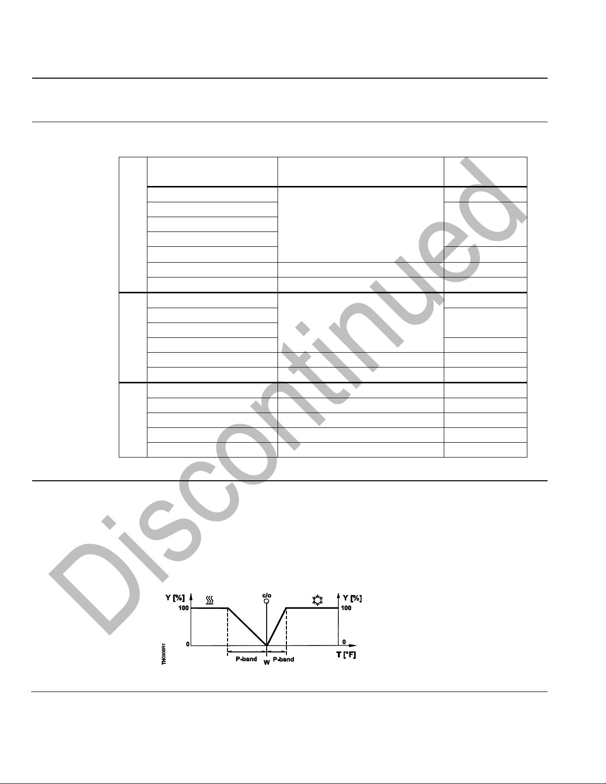
RDU20U
Figure 1. Heating/Cooling Modes.
C/O Changeover
P-band Proportional band
T Room temperature
W Room temperature setpoint
Y Y output percentage
NOTE: Diagram only shows
P-characteristic
Page 3
RDU20U, RDU50U and RDU50.2U Room Temperature Controllers Technical Instructions
with LCD for Heating and Cooling Systems Document Number 155-735
November 1, 2006
Siemens Industry, Inc. Page 3
Function, Continued
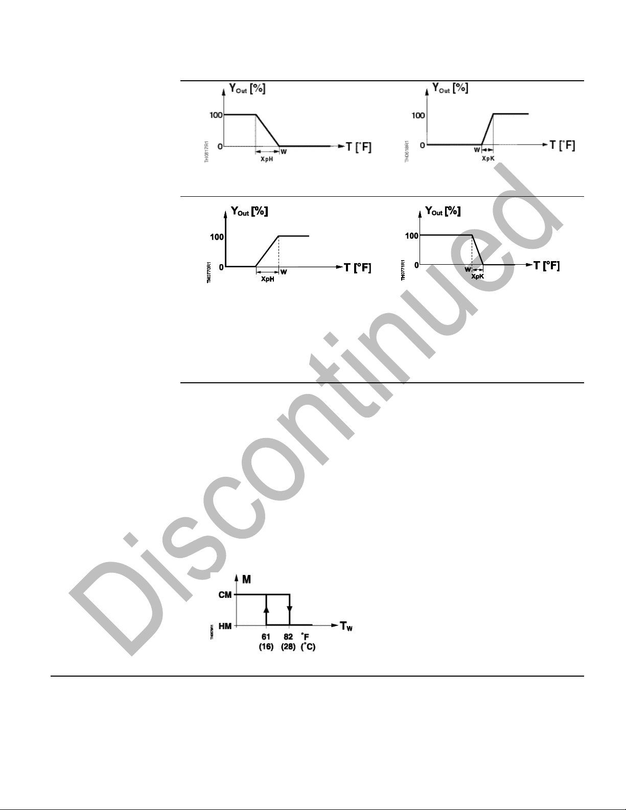
RDU50U and RDU50.2U
Figure 2. Heating Mode, RA.
(DIP Switch 2 in ON Position)
Figure 3. Cooling Mode, RA.
(DIP Switch 2 in ON Position)
Figure 4. Heating Mode, DA.
(DIP Switch 2 in OFF Position)
Figure 5. Cooling Mode, DA.
(DIP Switch 2 in OFF Position)
T Room temperature
XpH Proportional band heating
XpK Proportional band cooling
W Room temperature setpoint
YOut Output percentage
NOTE: The diagrams only show the proportional part of the P+I controller.
Automatic Changeover
RDU50U and RDU20U
The water temperature measured by the changeover sensor (QAH11.1) is used by the
controller to switch from heating to cooling mode, or vice versa. When the water
temperature is above 82°F (28°C), the controller switches to Heating mode; below
61°F (16°C), it switches to Cooling mode.
If immediately after switching on, the temperature is between the two changeover
points, the controller will start in Heating mode. The medium temperature is measured
at half-minute intervals and the operational status updated. The value of the current
temperature reading and the mode can be visualized temporarily by selecting
parameter P14.
In systems without automatic changeover, the temperature sensor can be replaced by
an external switch for manual changeover. In systems with continuous heating mode,
no sensor will be connected to the controller’s input. With continuous cooling mode, the
controller changeover input must be bridged.
CM Cooling mode
HM Heating mode
M Operating mode
TW Water temperature
Figure 6. Automatic Changeover Mode.
Page 4

Technical Instructions RDU20U, RDU50U and RDU50.2U Room Temperature Controllers
Document Number 155-735 with LCD for Heating and Cooling Systems
November 1, 2006
Page 4 Siemens Industry, Inc.
Inversion of Output
Signal
RU50U and RDU50.2U
The output signal can be inverted with the help of DIP Switch No. 2. If set to ON, 0V
corresponds to 0% travel and 10V to 100% travel (reverse acting heating/reverse acting
cooling). In the OFF position, 0V corresponds to 100% travel and 10V to 0% travel
(direct acting heating/direct acting cooling). See Figure 7 and Figure 8 for control
characteristics.
Heating-Cooling with
Minimum Limitation
Cooling
RU50U and RDU50.2U
Figure 7. Reverse Acting Heating/
Reverse Acting Cooling Function
Diagram.
Figure 8. Direct Acting Heating/Direct
Acting Cooling Function Diagram.
T Room temperature
YOut Output percentage
W Room temperature setpoint
XpH Proportional band heating
XpK Proportional band cooling
VR 0% to 100% minimum limitation of
cooling output
c/o Changeover
Minimum Limitation of
Cooling Signal
Using parameter P11, the cooling signal output can be limited to a minimum value
between 0 and 100% (0 to 10 Vdc). This can be used to ensure a minimum supply air
volume. When used in connection with a VAV controller, this setting must be taken into
account. See VR in Figure 7 and Figure 8.
Return Air Temperature
The RDU Controllers provide control depending on either the measured room
temperature or the return air temperature. The return air temperature measurement
overrides the internal measurement automatically if a QAH11.1 cable temperature
sensor is connected to input 4–3 (RDU50U and RDU50.2U) or 8–9 (RDU20U).
Parameter P12 shows which temperature sensor is currently active.
Display
(See Table 5)
• The settings for Parameters P12, P13, and P14 cannot be changed; they are for
displaying information settings only.
• The RDU50.2U Controller does not have a parameter setting or display for
Parameter P14.
• Parameter P14 (RDU20U and RDU50U) displays the current heat/cool changeover
temperature 32°F to 120°F (0°C to 49°C), and
100 = Input open or no sensor connected–Heating mode
00 = Input bridged–Cooling mode.
• For Parameter P12:
01 = The room temperature sensor is active.
02 = The return air temperature sensor is active.
• Parameter P13 displays the current room temperature 32°F to 120°F (0°C to 49°C).
Operating Modes
Normal Mode
Heating or cooling mode with automatic changeover. The controller maintains the
adjusted setpoint in normal operation.
Page 5

RDU20U, RDU50U and RDU50.2U Room Temperature Controllers Technical Instructions
with LCD for Heating and Cooling Systems Document Number 155-735
November 1, 2006
Siemens Industry, Inc. Page 5
Energy Saving Mode
A changeover switch can be connected to the dry contact (D1–GND). When the switch
closes its contact (due to an open window, for instance), the operating mode will
change from normal operation to Energy Saving mode. In this operating mode, the
heating or cooling setpoints are maintained (setting of control parameters P01 and
P02). If the Energy Saving mode setpoints are set to OFF, the controller will turn OFF
when the switch closes its contact.
When activated, the status input (D1–GND) overrides the
RDU20U/RDU50U/RDU50.2U setpoints as follows:
• Heating Mode → Parameter 01 becomes active
• Cooling Mode → Parameter 02 becomes active
• OFF → No effect
Mechanical Design
• The unit consists of two parts:
− Plastic housing−accommodates the electronics, the operating elements, and
the built-in room temperature sensor.
− Base plate−houses the wire terminations.
• The housing engages in the controller base and is secured with two screws.
• The screw terminals are mounted on the base plate.
• The DIP switches are located on the circuit board, which is accessible through the
rear of the housing. To access the DIP switches, remove the housing from the base
plate. See Figure 9.
Figure 9. DIP Switch Setting.
Table 3. RDU20U DIP Switches.
DIP Switch No.
Description
Position ON
Position OFF
1
LCD display
Room (return air)
temperature
Setpoint*
2
Control Algorithm
3-P modulating PI
control*
ON/OFF control
3
Not used
4
Temperature scale
Fahrenheit*
Celsius
Table 4. RDU50U and RDU50.2U DIP Switches.
DIP Switch No.
Description
Position ON
Position OFF
1
LCD display
Room temperature*
Setpoint
2
0 to 10 Vdc output logic
Cooling – RA
Heating – RA
Cooling – DA*
Heating – DA
3
Not used
N/A
N/A
4
Temperature scale
Celsius
Fahrenheit*
* Factory setting
Page 6

Technical Instructions RDU20U, RDU50U and RDU50.2U Room Temperature Controllers
Document Number 155-735 with LCD for Heating and Cooling Systems
November 1, 2006
Page 6 Siemens Industry, Inc.
Setting and
Operating Elements
Figure 10.
1 Display of the room or return air
temperature, setpoints, and control
parameters
2 Symbol used when displaying the
current room temperature
3 Normal operation
Energy Saving mode
4 Cooling valve open
Heating valve open
5 Buttons for adjusting the setpoints and
the control parameters
6 Slider switch for manual heat-off-cool
setting (RDU50.2U only)
Setting the Control
Parameters
A number of control parameters can be set to optimize the control performance. These
parameters can also be set during operation without opening the unit. A 24 Vac supply
to the controller is required to enable parameter adjustment.
The parameters can be changed as follows:
1. Press buttons "+" and "–" simultaneously for a minimum of three seconds and a
maximum of five seconds. Release the buttons and then press button "+" again for
approximately three seconds until the display shows “P01“.
2. Select the required parameter by repeatedly pressing buttons "+" or "–".
3. Press buttons "+" and "–" simultaneously. The current value of the selected
parameter appears, which can be changed by repeatedly pressing either button.
4. Press buttons "+" and "–" simultaneously again, or five seconds after the last press
of a button, to store the new value and display the parameter.
5. Repeat steps 2 through 4 to display and change additional parameters.
6. Wait ten seconds after the last display or setting. All changes will be stored and the
controller returns to normal operation.
Page 7

RDU20U, RDU50U and RDU50.2U Room Temperature Controllers Technical Instructions
with LCD for Heating and Cooling Systems Document Number 155-735
November 1, 2006
Siemens Industry, Inc. Page 7
Table 5. Control Parameters.
Parameter
Meaning
Setting Range
Factory
Setting
P01
Setpoint of heating in energy saving mode
(operating mode changeover switch activated)
OFF
41°F to 64°F (5°C to 18C)
(in increments of 1.0°F [0.5°C])
61°F (16C)
P02
Setpoint of cooling in energy saving mode
(operating mode changeover switch activated)
OFF
75°F to 95°F (24°C to 35C)
(in increments of 1.0°F [0.5°C])
82°F (28C)
P03
Minimum setpoint limitation in normal mode
41°F to 68°F (5°C to 20C)
(in increments of 1.0°F [0.5°C])
41°F (5C)
P04
Maximum setpoint limitation in normal mode
70°F to 95°F (21°C to 35C)
(in increments of 1.0°F [0.5°C])
95°F (35C)
P05*
Heat-cool changeover switching point cooling
50°F to 77°F (10°C to 25C)
(in increments of 1.0°F [0.5°C])
61°F (16C)
P06*
Heat-cool changeover switching point heating
81°F to 104°F (27°C to 40C)
(in increments of 1.0°F [0.5°C])
82°F (28C)
P07
Sensor calibration
-3 K to 3 K (1 Kelvin = 2°F)
0K
P08
P-band in heating mode (RDU50U and
RDU50.2U)
0.5 K to 4 K (1 Kelvin = 2°F)
(in increments of 1°F [0.5 K])
2K
P08
P-band in heating mode/switching differential
when ON/OFF output is selected (RDU20U)
0.5 K to 4 K (1 Kelvin = 2°F)
(in increments of 1°F [0.5 K])
2K
P09
P-band in cooling mode (RDU20 when
ON/OFF output selected)
0.5 K to 4 K (1 Kelvin = 2°F)
(in increments of 1°F [0.5 K])
1K
P10
Integration time
1 to 10 min. (in increments of 1 min.)
5 minutes
P11
Minimum output limitation in cooling mode
(normal operation) (RDU50U and RDU50.2U)
0 to 100% (in increments of 10%)
0%
P11
Actuator running time (RDU20U)
50 to 150 s (in increments of 10 s)
N/A
P12
Active temperature sensor (no setting, display
only)
01 = room temperature sensor active
02 = return air temperature sensor active
N/A
P13
Current room temperature reading (no setting,
display only)
32°F to 120°F (0°C to 49C) = current
temperature value
N/A
P14*
Current heat-cool changeover
temperature reading including indication
of current mode ( , ) (no setting, display
only)
• 100 = input open (no sensor
connected, heating mode ( )
• 41°F to 104°F (5°C to 40C) = current
temperature value
• 0 = input bridged, cooling mode ( )
N/A
P15
Test mode for checking the actuator
direction
NOTE: P15 can be turned off only if the
setting is back at “---” and by
pressing buttons + and –
simultaneously (RDU20U only).
“---“ = Output Y1 and Y2 OFF.
“OPE” = Output Y1 forced open
“CLO” = Output Y2 forced open
“---“
* Not applicable for RDU50.2U; LCD shows N/A.
Page 8

Technical Instructions RDU20U, RDU50U and RDU50.2U Room Temperature Controllers
Document Number 155-735 with LCD for Heating and Cooling Systems
November 1, 2006
Page 8 Siemens Industry, Inc.
Engineering Notes
RDU50U with heating-cooling changeover input 2–3 and
RDU20U with heating-cooling changeover input 7–8:
• In systems without automatic changeover, the temperature sensor can be replaced
by an external switch for manual changeover.
• In systems with Heating only mode, do not connect a sensor to the controller’s input.
• With Cooling only mode, the controller input must be bridged.
Mounting,
Installation and
Commissioning
Notes
• Check the position of the DIP switches and change them, if necessary.
• After applying power, the controller makes a reset, which takes approximately three
seconds; it is then ready to operate.
• Mount the unit on a wall of the room to be heated or cooled. Do not mount in direct
sunlight or near other heat or refrigeration sources. (See Figure 11.)
• Mounting height is approximately 60 inches (150 cm) above the floor.
(See Figure 11.)
• The connecting wires can be run to the controller from a recessed conduit box.
Figure 11. Acceptable Mounting Locations.
• Prior to fitting the changeover sensor on a pipe, thermal conductive paste must be
applied to the location on the pipe where the sensor is to be placed.
• The cables used must satisfy the insulation requirements for 24 Vdc potential.
• To access the wire terminal block, loosen the cover screw and open the plastic
cover. See Figure 12.
Figure 12. Accessing the Wire Terminal Block.
• Sensor inputs 4–3 and 2–3 (RDU50U and RDU50.2U) and 8–9 and 8–7 (RDU20U)
carry 24 Vdc potential. If the sensor's cables must be extended, they must be suited
for 24 Vdc voltage.
• Complete installation instructions are included with the controller.
Page 9

RDU20U, RDU50U and RDU50.2U Room Temperature Controllers Technical Instructions
with LCD for Heating and Cooling Systems Document Number 155-735
November 1, 2006
Siemens Industry, Inc. Page 9
Specifications
Power Supply
Operating voltage 24 Vac +20%
Frequency 50/60 Hz
Power consumption Maximum 4 VA
Control output 1–5 (RDU50U and RDU50.2U) 0 to 10 Vdc
Resolution 39 mV
Effective current Maximum +1 mA
Control output 4–6 (RDU20U) 24 Vac
Return air temperature input 4–3 QAH11.1 safety class 2
Changeover temperature input 2–3 NTC resistor 3K ohm at 77°F (25°C)
(RDU50U) and RDU20U
8–7 (RDU20U)
Dry contact D1 and GND
Contact sensing 6 to 15 Vdc/3 to 6 mA
Operating action Normally Open (NO)
Maximum cable length 16 AWG 262 feet (80 m)
for connection to terminals 4, 2 and D1
Operational data
Setpoint setting range 41°F to 95°F (5°C to 35°C)
Control deviation at 77°F (25°C) Maximum +1.6°F (0.9°C)
P-band in heating mode, adjustable
in 0.5K increments (1 Kelvin = 2°F) 0.5K to 4K
Factory setting 2K
P-band in cooling mode, adjustable
in 0.5K increments (1 Kelvin = 2°F) 0.5K to 4K
Factory setting 1K
Integral action time, adjustable 1 to 10 minutes
Factory setting 5 minutes
Setpoint (Energy Saving Mode ), heating 41°F to 65°F (5°C to 18°C)
Setpoint (Energy Saving Mode ), cooling 75°F to 95°F (24°C to 35°C)
Environmental
Conditions
Operation
Temperature 32°F to 122°F (0°C to 50°C)
Humidity <95% rh
Shipping and storage
Temperature (RDU50U and RDU50.2U) -13°F to 158°F (-25°C to 70°C)
(RDU20U) -13°F to 140°F (-25°C to 60°C)
Humidity <95% rh
Agency Approvals
Conforms to CE requirements
NEMA 1
General
Connection terminals Use solid wires or prepared stranded
wires. 2 × 16 AWG or 1 × 14 AWG
Maximum 20 AWG
Weight 0.5 lb (0.23 kg)
Housing color
Cover White
Base Gray
Page 10

Information in this publication is based on current specifications. The company reserves the right to make changes in specifications and models as
design improvements are introduced. Product or company names mentioned herein may be the trademarks of their respective owners.
© 2006 Siemens Industry, Inc.
Siemens Industry, Inc.
Building Technologies Division
1000 Deerfield Parkway
Buffalo Grove, IL 60089
+ 1 847-215-1000
Your feedback is important to us. If you have
comments about this document, please send
them to SBT_technical.editor@siemens.com
Document No. 155-735
Printed in the USA
Page 10
Wiring Diagrams
1 Operating voltage, 24 Vac negative
2 Operating voltage, 24 Vac positive
3 Operating voltage, 24 Vac positive
4 Control signal, opening 24 Vac
6 Control signal, closing, 24 Vac
7 Changeover, heat/cool input
8 Measuring neutral (sensors)
9 Remote temperature sensor
D1, Signal input for potential-free
GND operating mode changeover
Figure 13. RDU20U Wiring Diagram.
Figure 14. RDU50U Wiring Diagram.
Figure 15. RDU50.2U Wiring Diagram.
D1, GND Signal input for potential- free operating mode changeover switch
1 0 to 10 Vdc output
2 Heat/cool changeover sensor input
3 Measuring neutral
4 Remote temperature sensor input
5* Ground for control signal
6* Operating voltage, 24 Vac Neg
7 Operating voltage, 24 Vac Pos
* 5 and 6 are connected internally
Dimensions
Figure 16. Controller and Base Plate Dimensions in Inches (Millimeters).
 Loading...