

Page 1
s
Semi-flush mount room thermostats
with KNX communications
RDU341
Basic Documentation
Edition: 1.1
CE1P3172en
2015-06-08
Building Technologies
Page 2

2 / 68
Siemens RDU341 Basic Documentation CE1P3172en
Building Technologies 2015-06-08
Contents
1. About this document ........................................................................... 4
1.1 Revision history ..................................................................................... 4
1.2 Reference documents ............................................................................ 4
1.3 Before you start ..................................................................................... 5
1.3.1 Copyright ............................................................................................... 5
1.3.2 Quality assurance .................................................................................. 5
1.3.3 Documen t use / reque st to the reader .................................................... 5
1.4 T arg et audience, prerequ isites ............................................................... 6
1.5 Glossary ................................................................................................ 6
2. Summary .............................................................................................. 7
2.1 Typ es .................................................................................................... 7
2.2 Ordering ................................................................................................ 7
2.3 Functions ............................................................................................... 7
2.4 Integra tion via KNX bus ......................................................................... 8
2.5 Equipment combination s ...................................................................... 10
2.6 Accessories ......................................................................................... 1 1
3. Functions ........................................................................................... 12
3.1 T emperature control ............................................................................. 12
3.2 Operating modes ................................................................................. 13
3.2.1 Differen t w ays to influe nce the op era ting mod e .................................... 14
3.2.2 Commun ication examples .................................................................... 17
3.3 Room temperature setpoint s ................................................................ 19
3.3.1 Descr iption .......................................................................................... 19
3.3.2 Setting and adjus ting se tpo ints ............................................................ 20
3.4 Applica tions overview .......................................................................... 22
3.5 Additional functions .............................................................................. 23
3.6 Control sequ ences ............................................................................... 25
3.6.1 Seque nces overview (s etting via para meter P01) ................................. 25
3.6.2 Applica tion mode ................................................................................. 26
3.6.3 Minimu m and maximu m air volume ...................................................... 28
3.6.4 Single-du ct .......................................................................................... 29
3.6.5 Single-du ct with elec tric he ater ............................................................ 30
3.6.6 Setpoint s and sequences ..................................................................... 32
3.7 Control outputs .................................................................................... 33
3.7.1 Overview ............................................................................................. 33
3.7.2 Control outpu t s con figura tion (s ett ing via D IP sw itch es or tool) ............. 33
3.8 Multifunc tiona l input, digital inpu t.......................................................... 34
3.9 Handling faults ..................................................................................... 36
3.10 KNX communication s........................................................................... 36
3.10.1 S-mode................................................................................................ 36
3.10.2 L TE mode ............................................................................................ 3 6
3.10.3 Zone addre ss ing in LTE mode (in conjunction w ith Synco) ................... 37
3.10.4 Example of hea t ing and co ol ing de man d zon e ..................................... 39
3.10.5 Send heartbea t and receive timeo ut ..................................................... 40
3.10.6 Startup ................................................................................................. 40
3.10.7 Heating demand .................................................................................. 4 0
Page 3

3 / 68
Siemens RDU341 Basic Documentation CE1P3172en
Building Technologies 2015-06-08
3.10.8 Air demand .......................................................................................... 40
3.10.9 Electric heater interlock by supply air controller (LTE mode only) ......... 41
3.10.10 Primary fan over run af ter sw itching o ff the elec tric heat er ..................... 41
3.10.11 Fault function on KNX .......................................................................... 42
3.10.12 Emerge ncy contro l (LTE Mode only) .................................................... 4 3
3.11 Commun ication objects (S-mo de) ........................................................ 44
3.1 1.1 Over view ............................................................................................. 44
3.1 1.2 Description of commun ication objec ts .................................................. 45
3.12 Control parameters .............................................................................. 47
3.12.1 Parame ter setting via local HMI............................................................ 4 7
3.12.2 Parame ter setting / dow nload via tool ................................................... 48
3.12.3 Parame ters of the "Service level" ......................................................... 49
3.12.4 Parame ters of the "E xpert le vel with diagn os tics an d test" ................... 50
4. Handling ............................................................................................. 52
4.1 Mounting and inst allation ..................................................................... 52
4.2 Commissioning .................................................................................... 53
4.3 Operation............................................................................................. 55
4.4 Remote operation ................................................................................ 56
4.5 Disposa l .............................................................................................. 56
5. Supporte d KNX tools ......................................................................... 57
5.1 ETS ..................................................................................................... 57
5.1.1 Parame ter setting s in ETS ................................................................... 57
5.2 ACS tool .............................................................................................. 57
5.2.1 Parame ter settings in ACS ................................................................... 58
5.2.2 Operation and moni toring with ACS ...................................................... 59
5.2.3 Operation and monitoring with OZW772 ............................................... 61
5.2.4 Operation and monitoring with RMZ972-B ............................................ 61
6. Connection ......................................................................................... 62
6.1 Conne ction terminals ........................................................................... 62
6.2 Conne ction diagrams ........................................................................... 62
7. Mechanic al design ............................................................................. 63
7.1 Genera l ............................................................................................... 63
7.2 Dimensions .......................................................................................... 64
8. Tec hnical data .................................................................................... 65
Index …………………………………………………………………………………67
Page 4

4 / 68
Siemens RDU341 Basic Documentation CE1P3172en
Building Technologies 2015-06-08
1. About this document
1.1 Revision history
Edition Date Changes Section Pages
1.1 2015-06-08 Update the mounting notes, d isposal notes,
declaration information and connect ion diagrams
4.1
4.5
6.2
8
52
56
62
65
1.0 16 Jul 2010 First edition all
1.2 Reference documents
Subject Ref Doc No. Description
Semi-flush mount room
thermostats with KNX
communicati ons,
RDU341
[1] CE1N3172 Data Sheet
[2] CE1B3172 Operating Instructions
[3] CE1M3172 Mounting Instructions
KNX Manual [4] Handbook for Home and Building Control – Basic Principles
(http:// www.knx.org /knx-en/training /books-d ocument ation/knx-associati on-books /index.p hp
)
Synco and KNX (see
www.siemens.com /synco
)
[5] CE1N3127 KNX bus, Data Sheet
[6] CE1P3127 Communication via the KNX bus for Synco 700, 900 and
RXB/RXL, Basic Docum entati on
[7]
XLS template
in HIT
Planning and commissioning protocol,
communicati on Synco 700
[8] CE1N3121 RMB395 central control unit, Data Sheet
[9] CE1Y3110 KNX S-mode data points
[10] -- Product data for ETS
[11] CE1J3110 ETS product data compatibility list
[12] 0-92168en Synco Application Manual
DESIGO
engineering docum ents
[13] CM1Y9775 DESIGO RXB integration – S-mode
[14] CM1Y9776 DESIGO RXB / RXL integration – Individual Addressing
[15] CM1Y9777 Third-party integration
[16] CM1Y9778 Synco integration
[17] CM1Y9779 Working with ETS
Apogee
engineering docum ents
[18] 565-132 Installation I nstructions: KNX driver for PXC Modular
[19] 127-1676 Technical Spec Sheet: KNX driver for PXC Modular
[20] 140-0804 Technical reference for KNX driver
[21] 140-0804 Application 6205 point map for RDU
Page 5

5 / 68
Siemens RDU341 Basic Documentation CE1P3172en
Building Technologies 2015-06-08
1.3 Before you start
1.3.1 Copyright
This document m ay be duplicated and distributed only with the express permission
of Siemens, and may be passed only t o authorized persons or companies with the
required technic al knowledge.
1.3.2 Quality assurance
This document was prepared with great care.
· The contents of this document are checked at regular intervals
· Any corrections necessary are included in subsequent versions
· Docum ents are automatically amended as a consequence of modifications and
corrections to the products described
Please make sure that you ar e aware of the latest document revision date.
If you find lack of clarity while using this document, or if you have any criticisms or
suggestions, please contact the Product Manager in your nearest br anch office.
The addresses of the Siemens Regi onal Companies are available at
www.buildingtechnologies.si emens.com
.
1.3.3 Document use / request to the reader
Before using our products, it is important that you read the documents supplied
with or ordered at the same time as the products (equipm ent, applications, tools,
etc.) carefully and in full.
We assume that persons using our products and documents are authorized and
trained appropriately and have the technical knowledge required to use our
products as intended.
More information on the products and applications is available:
· On the intranet (Siemens employees only) at
https://workspace. sbt.siem ens.com/cont ent/00001123/def ault.aspx
· From the Siemens branch office near you
www.buildingt echnologies.siem ens.com or from your system supplier
· From the support team at headquarters fieldsupport-z ug.ch.sbt@ siemens.com if
there is no local point of contact
Siemens assumes no liability to the extent allowed under the law for any losses
resulting from a failure to comply with the aforementioned points or for the improper
compliance of the same.
Page 6
6 / 68
Siemens RDU341 Basic Documentation CE1P3172en
Building Technologies 2015-06-08
1.4 Target audience, prerequisites
This document assumes that users of the RDU KNX thermostats are familiar with
the ETS Professional and/or Synco ACS700 tools and able to use them.
It also presupposes that these users are aware of the specific conditions associated with KNX.
In most countries, specific KNX know-how is conveyed through training centers
certified by the KNX Association (see www.konnex.org/
).
For reference documentation, see section 1.2.
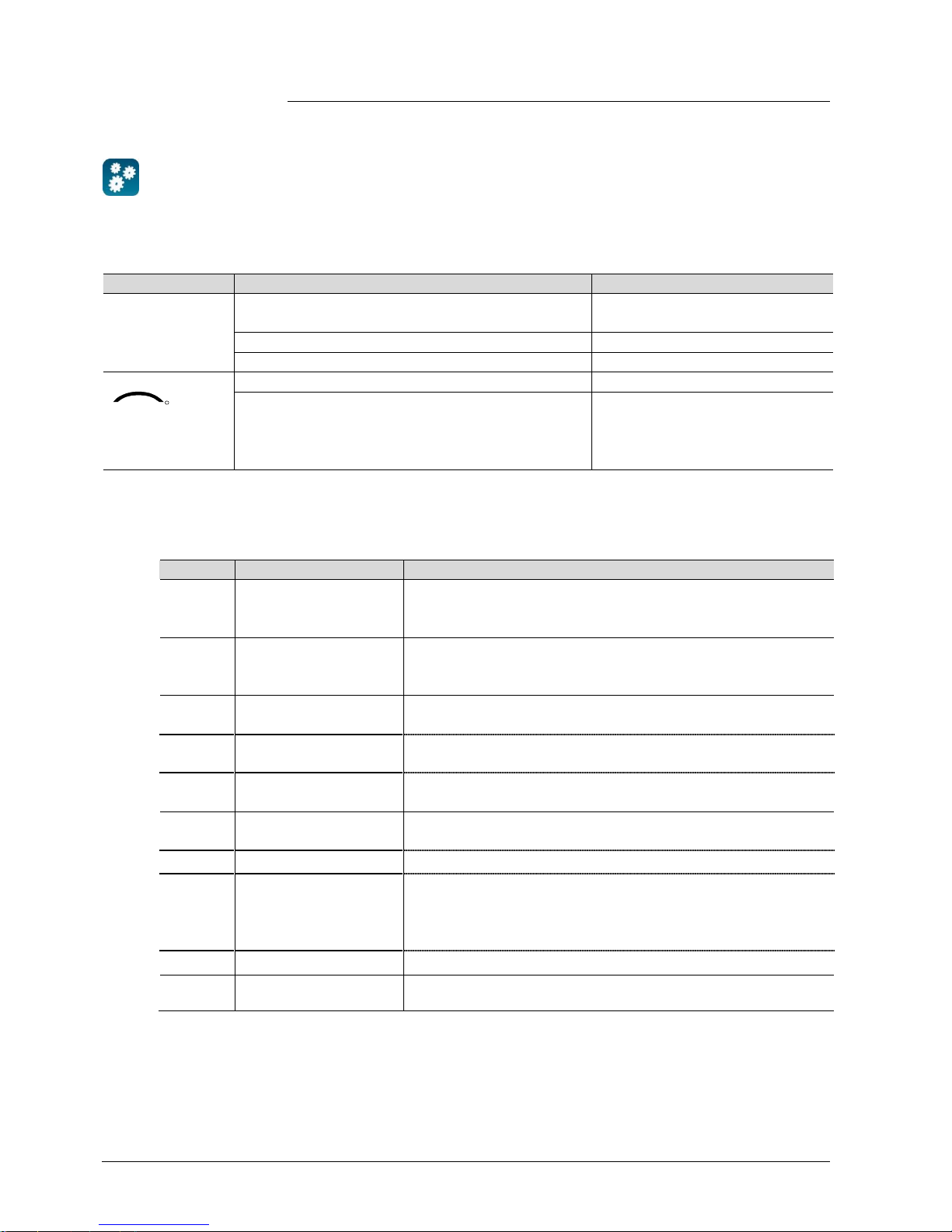
1.5 Glossary
The inputs, outputs and parameters of an application can be influenced in various
ways. These are identified by the following symbols in this document:
Parameters identified by this symbol are set usi ng ETS.
Parameters identified by this symbol are set using the ACS tool.
Setting RDU KNX parameters is only supported by the following tool
versions:
– ETS3f or higher
– ACS 700 version 5.11 or higher
Inputs and outputs identified by this symbol communicate with other KNX devices.
They are called communication objects (CO).
The communication objects of the RDU KNX thermostats work partly in S-mode,
partly in LTE mode, and partly in both. These objects are described accordingly.
A list of the parameters is shown in section 3.12.
ETS
ACS
STOP
Note!
KNX
R
Page 7

7 / 68
Siemens RDU341 Basic Documentation CE1P3172en
Building Technologies 2015-06-08
2. Summary
2.1 Types
Product number Stock number Operating voltage Control output s
Housi ng
color
3 pos ON/OFF DC 0..10 V
RDU341 S55770-T106 AC 24 V -- ü ü white
2.2 Ordering
· When ordering, please indicate both product no. / stock no. and name:
E.g. RDU341 / S55770-T106 room thermostat
· Order valve actuators separately
2.3 Functions
VAV systems via ON/OFF or modulating control outputs:
· Single-duct system
· Single-duct system with electric heater
The room thermostats are delivered with a fixed set of applications.
The relevant application is selected and activ ated during commissioning using one
of the following tools:
· Synco ACS
· ETS
· Local DIP switch and HMI
· Operat ing modes: Comfort, Economy (Energy Saving) and Protection
· Out puts for DC 0…10 V actuator and AC 230V electric heater (ON-OFF)
· Automati c or manual heating / cooling changeover
· Backlit display
· AC 24 V operating voltage
· Room temperat ure control via built-in temperature sensor or external room
temperature / return air temperature sensor
· Changeov er between heating and cooling mode (automatic via local sensor or
bus, or manually)
· Selecti on of applications via DIP switches or commissioning tool (ACS700)
· Sel ect operating mode via operating mode button on the thermostat
· Temporary Comfort mode extensi on
· Displ ay of current room temperature or setpoint in °C and/or °F
· Displ ay of outdoor temperature or time of day via KNX bus
· Minim um and maximum limitation of room temperature setpoint
· Mi nimum and maximum limitation of air flow signal DC 0...10 V
· Button lock (automatically or manually)
· 2 multifunctional inputs, freely selectable for:
– Operating mode switchover contact (keycard, window contact, etc.)
– Sensor for automatic heating / cooling changeover
– External room temperature or return air temperature sensor
Use
Features
Functions
Page 8

8 / 68
Siemens RDU341 Basic Documentation CE1P3172en
Building Technologies 2015-06-08
– Dew point sensor
– Electri c heat er enabl e
– Fault i nput
– Monitor input for temperature sensor or switch state
· Reload factory settings for commissioning and control parameters
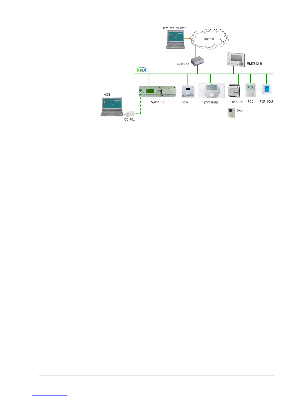
2.4 Integration via KNX bus
The RDU room thermostats can be integrated as follows:
· Int egrati on into Synco 700 system via LTE mode (easy engineering)
· Integrat ion into Synco living via group addressing (ETS)
· Int egrati on into DESIGO and Apogee via group addressing (ETS) or individual
addressing
· Integrat ion into third-party systems via group addressing (ETS)
The following KNX functions are available:
· Central tim e program and setpoints, e.g. when using the RMB795 central control
unit
· Out side temperature or time of day via bus displayed on thermostat
· Rem ote operation and monitoring, e.g. using the RMZ792-B bus operator unit
· Rem ote operation and monitoring with web browser using the OZW772 or
OZW775 web server
· Maxim um energy efficiency due to exchange of relevant energy information, e.g.
with Synco 700 controll ers (e.g. heating demand, cooling demand)
· Alarmi ng, e.g. external fault contact, condensation, etc.
· Monit oring input for temperature sensor or switch
Engineering and commissioning can be done using…
– local DIP switches / HMI
– Synco ACS700 service tool
– ETS
The RDU room thermostats are especially tailored for integration into the Synco
700 system and operate together in LTE mode. This extends the field of use of
Synco for individual room control in conjunction with VAV.
Thanks to S-mode extension to the QAX910 central apartment unit, communicating
room thermostats can be easily integrated into Synco living systems. Using the
S-mode data points of the central apartment unit, additional room information can
be exchanged with the room thermostat via KNX TP1 (RF function is not available
on the room thermostats). To make the integration, the ETS engineering tool is
required.
Synco 700
Synco living
Page 9
9 / 68
Siemens RDU341 Basic Documentation CE1P3172en
Building Technologies 2015-06-08
Synco 700 Building automation and control system (BACS)
Synco living Room automation and control system
RDG..., RDF…, RDU… Room thermostats
OZW772 (or OZW775) Web server
RMZ792-B Bus operator unit
QAW... Room unit
ACS Engineering and Service tool
OCI700, OCI702 Interface for ACS
RXB, RXL Room controllers
QAX Room unit for RXB / RXL room controllers
The RDU KNX devices can be integrated into the Siemens building automation and
control systems (BACS) DESIGO / Apogee or into 3rd-party systems. For
integration, either S-mode (group addressing) or indiv idual addressing can be
used. The workflow for integration into DESIGO / Apogee is the same as with
standard KNX devices.
Synco to po logy
Legend:
DESIGO, Apogee and
third-party systems
Page 10

10 / 68
Siemens RDU341 Basic Documentation CE1P3172en
Building Technologies 2015-06-08
2.5 Equipment combinations
Type of unit Product no.
Data
sheet
Cable temperat ure sensor, cable
length 2.5 m
NTC (3 kW at 25 °C)
QAH11.1
1840
Room temperature sensor
NTC (3 kW at 25 °C)
QAA32
1747
Condensation detector / Supply unit
QXA2000 /
QXA2001 /
AQX2000
1542
Electrical actuator, DC 0..10 V
(for radiator valve)
SSA61...
4893
Electrical actuator, DC 0..10 V
(for 2 and 3 port valves / V…P45)
SSC61…
4895
Electrical actuator, DC 0..10 V
(for small valve 2,5 mm)
SSP61…
4864
Electrical actuator, DC 0..10 V
(for small valves 5.5 mm)
SSB61...
4891
Electrical actuator, DC 0..10 V
(for Combi-valve VPI45)
SSD61...
4861
Electromotori c actuator, DC 0..10V
(for valves 5.5 mm)
SQS65…
4573
Thermal actuat or, DC 0..10 V
(for small valves and radiator
valves)
STS61
4880
DC 0…10 V damper actuator
GQD161…
4605
GDB161…
4634
GLB161…
GMA161…
4614
GEB161…
4621
GCA161…
4613
GBB161…
4626
GIB161…
VAV compact controller
GDB181.1E/3
3544
GLB181.1E/3
DC 0…10 V
valve actuators
DC 0…10 V
damper actuators
Page 11

11 / 68
Siemens RDU341 Basic Documentation CE1P3172en
Building Technologies 2015-06-08
2.6 Accessories
Description
Product no /
Stock no.
Data
sheet
Changeover mounting kit (50 pcs / package)
ARG86.3
N3009
Plastic mounting bracket for RDU semi-flushmount thermostats for increasing the headroom in
the conduit box by 10 mm
ARG70.3
N3009
Conduit box for semi-flush mounted thermostat
ARG71 /
S55770-T137
N3009
KNX power supply 160 mA (Siemens BT LV)
5WG1 125-1AB01
--
KNX power supply 320 mA (Siemens BT LV)
5WG1 125-1AB11
--
KNX power supply 640 mA (Siemens BT LV)
5WG1 125-1AB21
--
Page 12
12 / 68
Siemens RDU341 Basic Documentation CE1P3172en
Building Technologies 2015-06-08
3. Functions
3.1 Temperature control
Setting of the control parameters (P01, etc., mentioned throughout the document)
is described in section 3.12.
The thermostat acquires the room temperature via built-in sensor, external room
temperature sensor (QAA32), or external return air temperature sensor (QAH11.1),
and maintains the setpoi nt by delivering actuator control commands to heating
and/or cooling equipment. The following cont rol outputs are available:
· VAV box / damper: Modulating PI/P control with DC 0...10 V
· El. heater: ON/OFF control (2-position)
The switching differential or proportional band is 2 K for heating mode and 1 K for
cooling mode (adjustable via parameters P30 and P31).
The integral action time for modulating PI control is 5 minutes (adjustable via
parameter P35).
The display shows the acquired room temperature or the Comfort setpoint, selectable via parameter P06. The factory setting displays the current room temperature.
Use parameter P04 to display the room temperature or setpoint in °F rather than
°C as needed.
The acquired room tem perature (internal or external sensor) is al so available as
information on the bus.
· W ith automatic changeover or continuous heating / cooling, symbols
/
indicate that the system currently heats or cools (heating or cooling output is
activated).
· With manual changeover (P01 = 2), symbols
/ i ndicate that the system
currently operates in heating or cooling mode. Thus, the symbols are displayed
even when the thermostat operates in the neutral zone.
Concurrent displ ay of the current temperature or setpoint in °C and °F (parameter
P07 = 1) is possible on the thermostats.
The outside temperat ure can be displayed on the room thermostat by setting
parameter P07 = 2. This temperature value has only information character.
In LTE mode, the outside temperature can only be received on outside temperature
zone 1.
In S-mode, the corr espondi ng communication object needs to be bound with a
KNX sensor device.
Time of day via bus can be displayed on the room thermostat by setting parameter
P07 = 3 or 4. The display format is either in 12- or in 24-hour format.
The information can be received from a Synco controller with time master
functionality or any other KNX device if the corresponding communication object is
bound.
General note:
Parameters
Temperature control
Display
KNX
R
Room temperature
/
Concurrent displ ay of
°C and °F
KNX
R
Outside temperature via
bus
KNX
R
Time of day via bus
Page 13

13 / 68
Siemens RDU341 Basic Documentation CE1P3172en
Building Technologies 2015-06-08
3.2 Operating modes
The thermostat's operating mode can be influenced in different ways (see below).
Specific heating and cooling setpoi nts are assi gned to each operating mode.
The thermostat sends the effective room operating mode on the bus.
The following operating modes are available:
In Auto Timer mode the room operating mode is commanded via bus.
Auto Timer is replaced by Comfort when no time schedule via bus is present
In Comfort mode, the thermostat maintains the Comfort setpoint. This setpoint can
be defined via parameters P8, P9 and P10.
It can be locally adjusted via the +/- buttons or via bus.
In Comfort mode, the fan can be set to automatic or manual fan speed: Low,
medium or high.
The setpoints (less heating and cooling than in Comfort mode) can be defined via
parameters P11 and P12.
The thermostat switches to Economy mode when...
– the operating mode button is pressed (only possible if parameter P02 is set to 2)
– Ec onomy is sent via bus
– an operating mode switchover contact (e.g. keycard contact presence detector,
window contact) is active.
The contact can be connected to multifunctional input X1, X2.
Set parameter P38 / P40 to 3 (P02 is irrelevant) *)
– "Window state" is sent via bus, e.g. from a KNX switch or a KNX presence
detector (P02 is irrelevant) *)
*) Operating mode switchov er: Only one input source must be used, either local
input X1/X2 or KNX bus.
User operations are ineffec tive and “OFF” is displayed if the operating mode
switchover contact is active, or if "Window state" is sent via bus.
In Protection mod e, the system is...
– protected against frost (factory setting 8 °C, can be disabled or changed via
P65)
– protected against overheating (factory setting OFF, can be enabled or changed
via P66)
No other operating mode can be selected locally if Protection mode is commanded
via bus.
and are displayed.
KNX
R
Room operating mode:
State
Auto Time r
Comfort
Economy
KNX
R
Room operating mode:
Window state
Note:
Protection
Page 14
14 / 68
Siemens RDU341 Basic Documentation CE1P3172en
Building Technologies 2015-06-08
3.2.1 Different ways to influence the operating mode
The operating mode can be influenced by different interventions.
The source of the effective room operating mode state can be monitored using the
"Cause" diagnostic data point in the ACS tool, operator unit RMZ792-B or web
server OZW772.
Source Description Value of DP "Cause"
Local operation
via operating
mode button
· Operati ng mode is not Auto Tim er
· No time schedule via bus
Room operating mode selector
(preselection)
· Temporary Comfort extension is active “Timer” function
· Operating mode switchov er contact Room operating mode contact
Bus command
KNX
R
Room op. mode
· "Window state" sent via bus Room operating mode contact
· Time schedule available via bus
à local operating mode is set to Auto Timer
· Tim e schedule sends Protection mode via bus
à operating mode cannot be changed locally
Time switch
The following table shows the priorities of diff erent interventions.
A lower number means a higher priority.
Priority Description Remark
Commissioning In parameter setti ng mode (highest priority), you c an always
command an operating mode independent of all other settings or
intervention via bus and local input.
Protection mode via bus
from time schedule
Protection mode, sent by a time schedule, has pri ority 2.
It cannot be overridden by the user nor by an operating mode
switchover contact .
Operating mode
switchover contact
If the contact is closed, the operating mode changes to Economy.
This overrides the operating mode on the t hermostat.
"Window state" via bus "Window state" sent via bus has the same effect as the operat ing
mode switchov er contact.
Note: Only one input source must be used, either local input
X1/X2 or KNX bus.
a
Operating mode button The user can switch the operating mode using the operating
mode button.
b
Operating mode via bus The operating mode can be changed via bus
c
Temporary extended
Comfort mode via
operating mode button
The operating mode can be temporarily set from Economy to
Comfort by pressing the operating mode button, if...
– Econom y was sent via bus
– ex tended Comfort period >0 (parameter P68)
The last intervention wins, either locally or via bus
Time schedule via bus
The operating mode sent via bus can be overridden by all other
interventions. Exception: Protection mode has priority 2.
Source for change of
operating mode
ACS
Priority of operating
mode inter v e ntions
Page 15
15 / 68
Siemens RDU341 Basic Documentation CE1P3172en
Building Technologies 2015-06-08
If a time schedule via bus is present, e.g. from central control unit, then the Auto
Timer mode
is active. The thermostat automatically changes between Comfort
and Economy according to the time schedule via bus.
The display shows the Auto Timer mode symbol
along with the symbol for the
effective room operating mode (Comfort
or Economy ).
By pressing the operating mode button, you can change to another operating
mode.
Automatic fan is the default fan speed in Auto T imer mode.
Each time the time schedule sends a new operating mode (switching event), the
operating mode of the thermostat is set back to Auto Timer mode. This is to assure
that the room temperature is maintained according to the time schedule.
If the time schedule sends Precomfort mode, then this mode will be transformed
either into Economy (factory setting) or Comfort (selectable via parameter P88).
No intervention is possible neither by the user nor by an operating mode switchover contact, if Protection mode is set by the time schedule. OFF flashes on the
display when the user presses a button.
The operating mode can be selected locally via the operating mode button.
The behavior of t he operating mode button (user profile) can be defined via
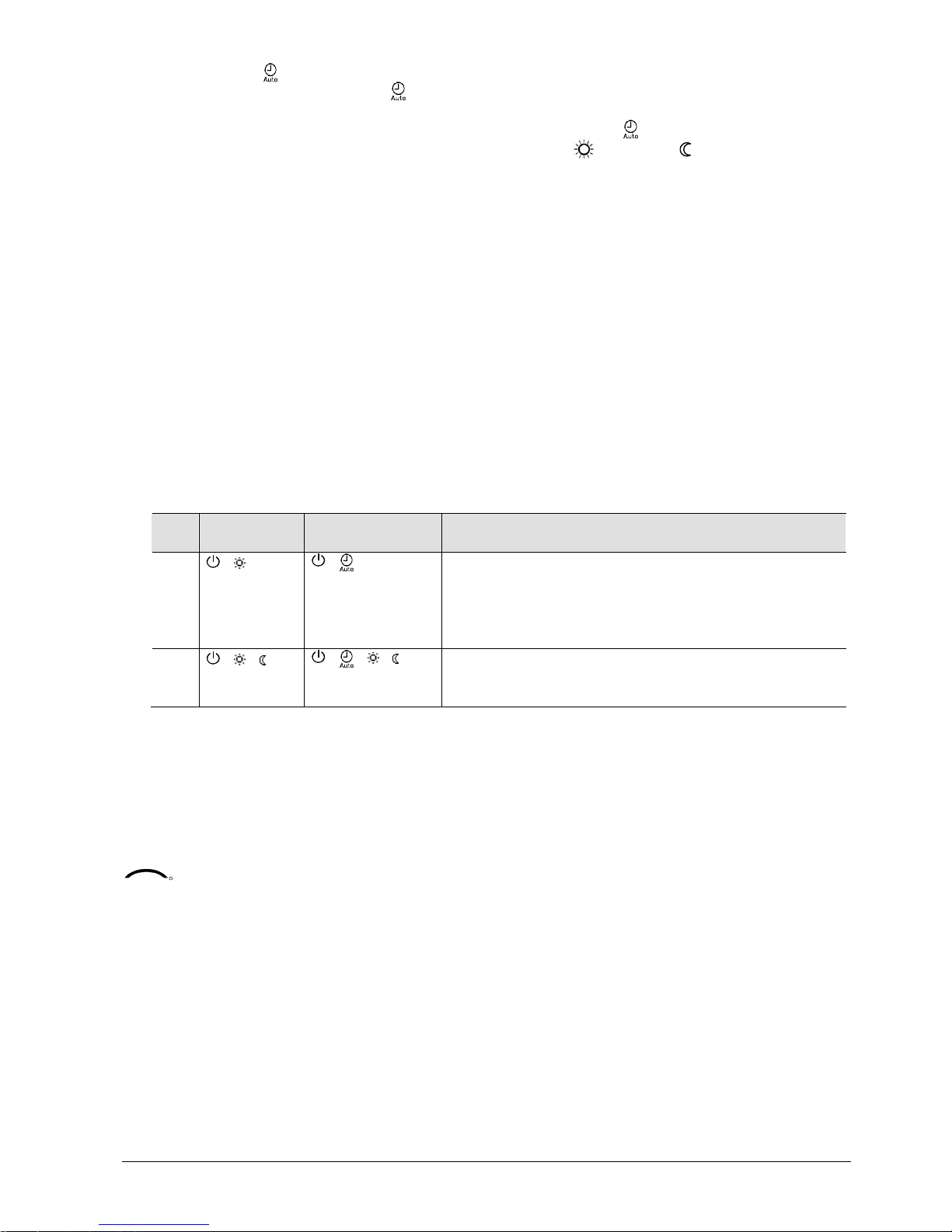
parameter P02, factory setting is P02 = 1.
P02 Without time
schedule
With time schedule via bus
Description
1 à
à
· Switching m anually between 2 modes, Econom y i s not
available (f actory sett ing)
· Suit ed for hotel guest rooms or commercial buildings.
· If a time schedule via bus is available, then the Comfort
mode can be temporarily ex tended (see below)
2 à à
à à à
· Switching m anually between 3 modes
· Suit ed for homes and rooms where manual switching to
Economy mode is desired
The thermostat can be forced into Economy mode (e.g. when a window is opened,
when a presence detector signals "no one present", when the keycar d of a hotel
room is withdrawn, etc). The contact can be connected to multifunctional input X1,
X2. Set parameter P38, P40 to 3.
If the operating mode switchover contact is active, pressing the operating mode
button will show “OFF” (blinking).
The function is also available via the KNX signal "Window state", e.g. from a KNX
switch or a KNX presence detector.
Note: Only one input source must be used, either local input X1/X2or KNX bus.
User operations are ineffec tive and “OFF” is displayed if the operating mode
switchover contact is active, or if "Window state" is sent via bus.
Auto Timer mode
with time schedule via
bus
Behavior when bus
sends new operating
mode
Precomfort via bus
Behavior when bus
sends Protection
Availability of Economy
mode
Operating mode
switchover contact
(window contact)
KNX
R
Room operating mode:
Window state
Page 16

16 / 68
Siemens RDU341 Basic Documentation CE1P3172en
Building Technologies 2015-06-08
Comfort mode can be t emporarily extended (e.g. working after business hour or on
weekends) when the thermostat is commanded to Economy mode.
The operating mode button switches the operating mode back to Comfort for the
period preset in P68.
Press the operating mode button again to stop the timer.
The following conditions must be fulfilled:
· Mode selecti on via operating mode button is set to “Protection-Auto” (P02 = 1)
and parameter P68 (extend Comfort period) is greater than 0
· The time schedule via bus is Economy or Operating mode switchover is active
During the temporary Comfort mode extension, symbol
appears.
If parameter P68 (extend Comfort period) = 0, extended Comfort cannot be
activated; pressing the operating mode button will swit ch the thermostat to
Protection.
Temporary timer to
extend the Comfort
mode
Page 17
17 / 68
Siemens RDU341 Basic Documentation CE1P3172en
Building Technologies 2015-06-08
3.2.2 Communication examples
The following ex amples show two typical applications of a central tim e schedule in
conjunction with local control of the room operating mode.
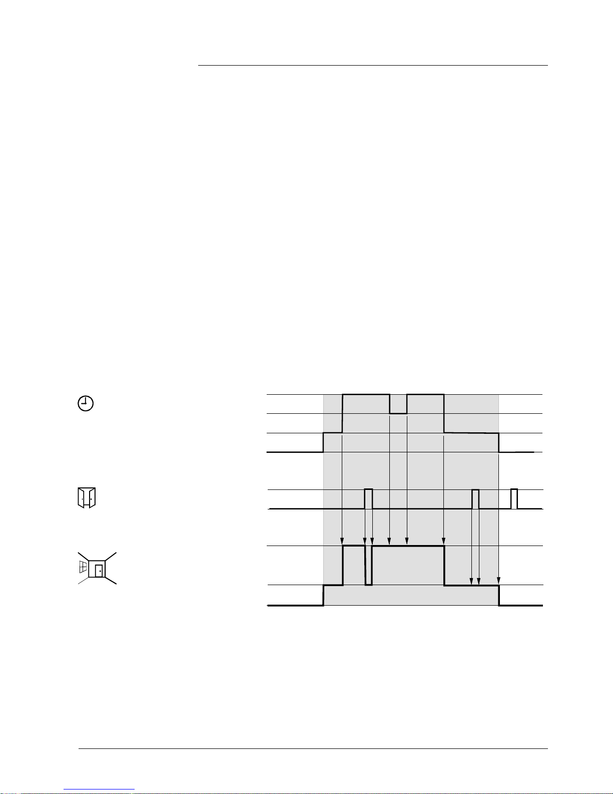
The room operating mode in rooms 1…2 of a building is determi ned by the time
schedule. Window contacts are fitted in all rooms.
The following condi tions are specified:
The rooms are used and controlled by the time schedule as follows:
– Night setback from 17:00 to 08:00 (Economy)
– Protection from 20:00 to 06:00
– Lunch break from 12:00 to 13:00 (Precomfort)
The substitution (parameter P88) for Precomfort via bus is set on the thermostats
as follows:
– Room 1: Comfort (1)
– Room 2: Economy (0)
Operating mode switchover
In room 1, the window is opened briefly, once in the morning, once in late
afternoon and once at night (1). Only the opening in the morning has a direct
impact on the effective room operating mode.
During lunch break, the time schedule changes to Precomfort. The mode remains
in Comfort as set by parameter “Transformation Precomfort” (P88 = 1).
Time schedule
Window contact
Room 1
Effective room
operating mode
Room 1
Comfort
Precomfort
Economy
Protection
Window open
Window closed
Comfort
Economy
Protection
08:00
17:0013:0012:00
1)
06:00
20:00
1)
1)
2)
3171Z91
Example 1
Page 18
18 / 68
Siemens RDU341 Basic Documentation CE1P3172en
Building Technologies 2015-06-08
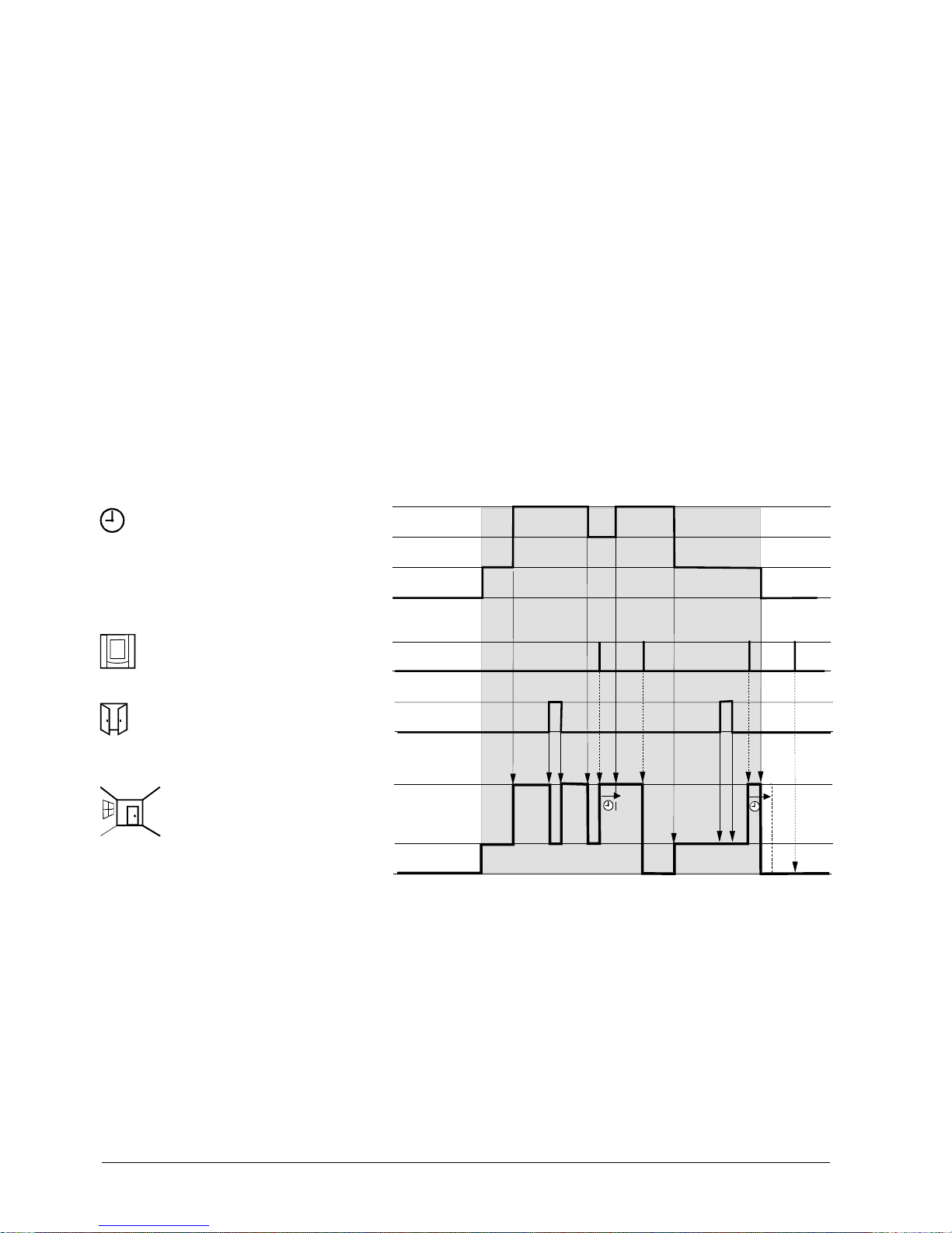
Interaction of user operation (operating mode button) and central time
schedule
In room 2, the window is opened briefly, once in the morning and once at night (1).
Only the opening in the morning has a direct impact on the effective room operating mode.
With the operating mode button, the operating mode can be changed between
OFF and Auto or temporary Comfort extension respectively.
· During lunch break , the time schedule changes to Precomfort.
The mode of the thermostat c hanges to Economy as set by parameter
“Transformation Precomf ort” (P88 = 0) (6)
· During lunch break, the user changes the operating mode to Comfort
(temporary Comfort extension) by pressing the operating mode button (2).
At 13:00, the timer is reset due to mode change of the central time schedule
· In the aft ernoon, the user switches the thermostat off by pressing t he operating
mode button (3). At 17:00 the user setting is reset to Economy by the time
schedule
· At 19:30, the user again extends the Comfort mode (4). At 20:00, the timer i s
reset by the time schedul e
· After 20:00, pressing the operating mode button has no effect, as the central
time switch sets the thermostat to Protection (5)
Time schedule
Room operating
mode
Operating mode
button on the
thermostat
Window contact
Room 2
Effective room
operating mode
Room 2
Comfort
Precomfort
Economy
Protection
Pressed
Window open
Window closed
Comfort
Economy
Protection
08:00
17:0013:0012:00
06:00
20:00
1)
1)
5)
2)
3)
4)
6)
3171Z92
Example 2
Page 19
19 / 68
Siemens RDU341 Basic Documentation CE1P3172en
Building Technologies 2015-06-08
3.3 Room temperature setpoints
3.3.1 Description
The factory setting for the Comfort basic setpoint is 21 °C and can be changed in
the thermostat’s EEPROM v ia parameter P08 or via bus with communication object
" Comfort basic setpoint". The last intervention always wins.
The Comfort setpoint can be adjusted via +/- buttons, or via bus from a remote
device like a touchpanel, operating unit, etc.
The last interv ention always wins.
If the “Temporary setpoint” function is enabled via parameter P69, the Comfort
setpoint adjusted via the +/- buttons or vi a bus is set back to the Comfort basic
setpoint stored in P08 when the operating mode changes.
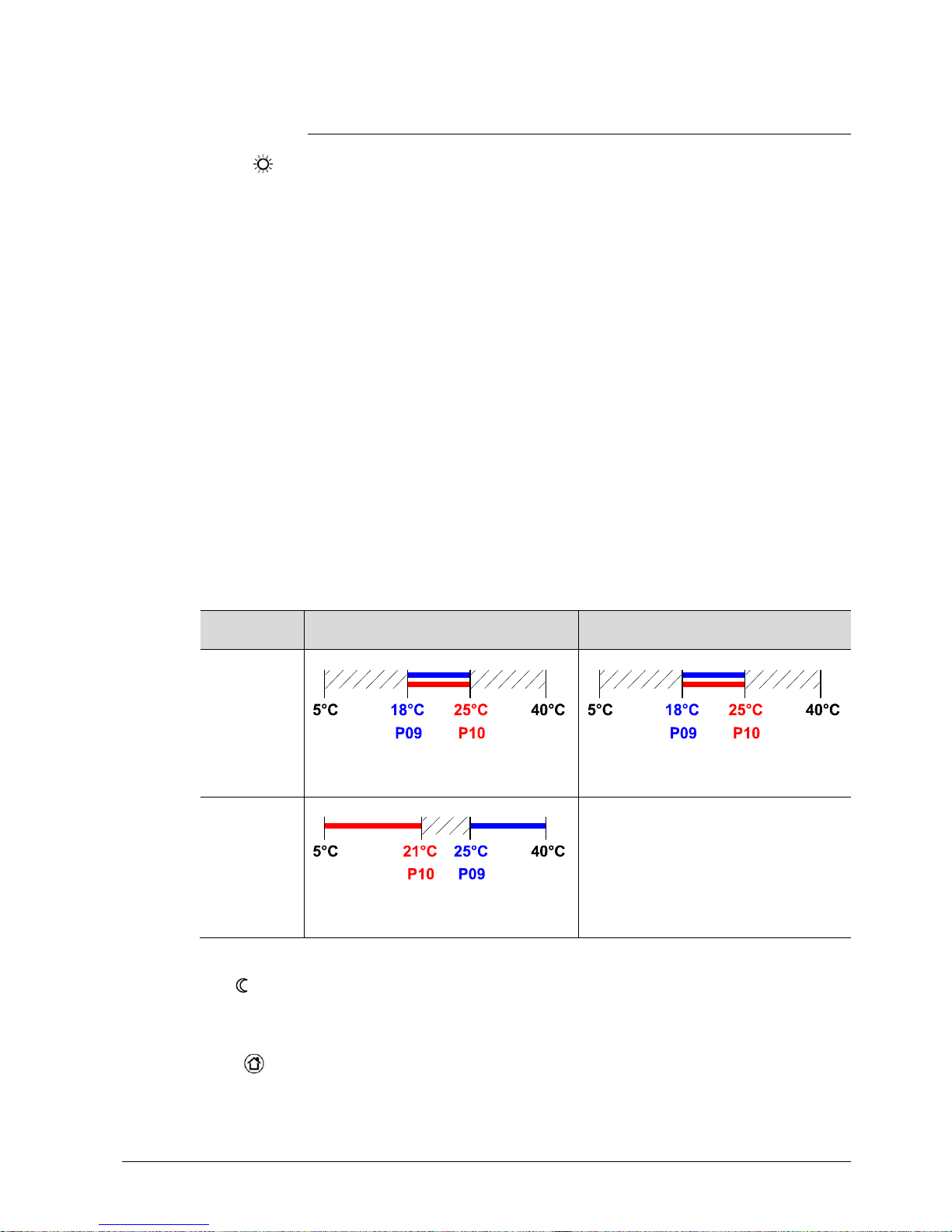
For energy saving purposes, the setpoint setting range can be limited to minimum
(P09) and maximum (P10).
· If the m inimum limit P09 is set lower than the maximum limit P10, both heating
and cooling are adjustable between these 2 limits
· For heating or cooling applications (e.g. single duct):
– The setting range in cooling mode is from P09…40 °C in place of 5…40 °C
– The setting range in heating mode is from 5…P10 °C in place of 5…40 °C
· For heating and cooli ng applications (e.g. single duct wit h el. heater):
– P09 is the setpoint for cooling and P10 the setpoint for heating
– The setpoint can no longer be adjusted via the rotary knob
Examples Single duct
Heating OR cooling
Single duct & el. heater
Heating AND coo li ng
P09 < P10
Cooling setpoi nt adjustable 18…25 °C
Heating setpoint adjustable 18…25 °C
Cooling setpoi nt adjustable 18…25 °C
Heating setpoint adjustable 18…25 °C
P09 ≥ P10
Cooling setpoi nt adjustable 25…40 °C
Heating setpoint adjustable 5…21 °C
Cooling fixed = 25 °C (P09)
Heating fixed = 21 °C (P10)
Use control parameters P11 and P12 to adjust the Economy mode setpoints.
The heating setpoint is factory-set to 15 °C, and the cooling setpoint to 30 °C.
Use control parameters P65 and P66 to adjust the Protection mode setpoints.
The heating setpoint is factory-set to 8 °C (frost protection) and t o OFF for cooling.
Comfort mode
Temporary setpoi nt
Setpoint limitation
P09 < P10
P09 ≥ P10
Economy mode
Protection mode
Page 20
20 / 68
Siemens RDU341 Basic Documentation CE1P3172en
Building Technologies 2015-06-08
If a setpoint (Economy or Protection) is set to OFF, the thermostat does not control
the room temperature in the corresponding mode (heating or cooling).
This means no protective heating or cooling function and thus risk of frost in
heating mode or risk of overtemperature in cooling mode!
The Economy setpoints are accessible at the service level (P11, P12); the
Protection setpoints at the expert level (P65, P66).
3.3.2 Setting and adjusting setpoints
Room temperature setpoints can be
– set during commissioning
– adjusted during runtime
The source can be
– the local HMI
– a tool
– a central control unit
The thermostat stores the setpoi nts
– in EEPROM i n the form of parameters
– in the runtime memory
The table below shows the interr elations:
Setpoint setting
Sto
red in EE PROM
of thermostat
Commis
sioning
– HMI
– Tool download
Input LTE mode
Input S
-mode
Comfort basic setpoint
Dead zone Comfort 1)
Setpoints Heating
Setpoints Cooli ng
Comfort basic setpoint P08 Comfort basic setpoint
P33 Dead zone Comfort 1)
Setpoint Economy Heating
Setpoint Economy Cooling
Setpoints Heating
Setpoints Cooli ng
P11 Economy Heating
P12 Economy Cooling
Setpoint Prot ection Heating
Setpoint Prot ection Cooling
P65 Protection Heating
P66 Protection Cooling
Current
runtime
setpoints in
thermostat
Setpoint
adjustment
New
current
runtime setpoints
in thermostat
Input LTE mode
2)
Input S
-mode3)Local ope
-
ration 3)
Comfort setpoi nt Setpoint shift H
Setpoint shift C
Comfort setpoint + / - buttons Comfort setpoint
Economy Heating
Economy Cooling
Setpoint shift H
Setpoint shift C
Economy Heating
Economy Cooling
Protection Heati ng
Protection Cooling
Protection Heating
Protection Cooling
Effective room operating mode Current setpoint (used by the thermostat for temperature control)
Caution
KNX
R
Comfort basic setpoint
Comfort setpoint
Page 21

21 / 68
Siemens RDU341 Basic Documentation CE1P3172en
Building Technologies 2015-06-08
1) Only required for heating AND cooling applications (see section 3.6.6)
2) The shift is added to the local shift (LTE mode only)
3) The last intervention wins, either S-Mode input or local operation
The current setpoint (used by the thermostat for temperature control) is available
on the bus for use in the central control unit.
· The supported communicati on objects are different in LTE mode and S-mode
· Change s via the local HMI or via KNX have the same priority (last always wins)
· Adj usting the Comfort basic setpoint will reset the runtime Comfort setpoint to
the basic setpoint
· Central setpoi nt shift is used for summer / winter compensation in particular
· Setpoi nt shift does not affect the setpoints stored in parameters P08, P11, P12,
P33
· Local shift and central shift are added together
· Appli es only to Comfort and Economy setpoints; Protection setpoints are not
shifted central ly
· The resulting (current ) setpoint heating and cooling is limited by the Protection
setpoint; if Protection setpoint is OFF, then minimum 5 °C and maximum 40 °C
are used
· The resulting setpoint s for cooling and heating of the same operating mode have
a minimum distance of 0.5 K between them
· The result of local and central shift, together with the room operating mode, is
used by the thermostat for temperature control (current setpoint)
KNX
R
Current setpoint
General notes:
Notes on setpoint
adjustment (LTE mode
with Synco only)
Page 22

22 / 68
Siemens RDU341 Basic Documentation CE1P3172en
Building Technologies 2015-06-08
3.4 Applications overview
The thermostats support the f ollowing applications, which c an be configured using
the DIP switches inside the front panel of the unit or a commissioning t ool.
All DIP switches need to be set to OFF (remote configuration, factory setting) to
select an application via commissioning tool. In this case the output signal type
needs to be set in ACS as well.
The tool offers the applications printed in bold text (basic applications).
Application and output signal Diagram DIP switches
Remote configuration
via commissioning tool (factory setting)
· Synco ACS
· ETS
1ON2 3
Single duct
· Single duct heating or cooli ng
DC 0...10 V output signal normal
3192S07
B1
T
MVM
V
YV
1ON2 3
· Single duct heating or cooling
DC 10...0 V output signal inverted
1ON2 3
Single duct with electric heater
· Single duct heating and cooling, with
electric heater
DC 0...10 V output signal normal
3192S08
YE
B1
T
MVM
V
YV
1ON2 3
· Single duct heating and cooling, with
electric heater
DC 10...0 V output signal inverted
1ON2 3
Page 23

23 / 68
Siemens RDU341 Basic Documentation CE1P3172en
Building Technologies 2015-06-08
3.5 Additional functions
The supply air temperature sent by the primary controller indicates whether cool or
warm air is supplied.
The controller determines the necessity to open or close the air damper according
to the supply air temperature, the room temperature setpoint and the current room
temperature.
If no Supply air temperature is available via bus, then the air changeover is cooling
per default.
With application “Single duct”, the changeover can also be accomplished via a
local multifunctional input X1/X2 (parameter P38, P40).
Only one input source must be used, either local input X1/ X2 or KNX, and
parameter “control sequence” must be set to automatic heating / cooling
changeover (parameter P01 = 3).
Functionality of the local changeover input see below.
See also section 3.8.
If a cable temperature sensor (QAH11.1 + ARG86.3) is connected to X1 / X2, and
parameter P38 / P40 is = 2, the water or supply air temperature acquired by the
sensor is used to change over from heating to cooling mode, or vice versa. When
the water / air temperature is above 28 °C (parameter P37), the thermostat
changes over to heating mode, and to cooling mode when below 16 °C (parameter
P36).
If the water / air temperature is between the 2 changeover points immediately after
power-up, the thermostat starts in heating mode.
The water / air temperature is acquired at 30-second intervals and the operating
state is updated accordingly.
M Operating mode C oolin g m od e
Tw Water temperature
Heating m od e
The QAH11.1 cable temperature sensor for automatic heating / cooling changeover
can be replaced by an external switch for manual, remote changeover:
Contact open à heating mode
Contact closed à cooling mode
The sensor or switch can be connected to input termi nal X2 or X1, depending on
the commissioning of the inputs (P38, P40).
See also section 3.8.
Air heating / cooling
changeover
KNX
R
Supply air temperature
Automatic heating /
cooling changeover via
changeover sensor
Changeover switch
Page 24

24 / 68
Siemens RDU341 Basic Documentation CE1P3172en
Building Technologies 2015-06-08
If manual heating / cooling changeover is commissioned (P01 = 2), then heating /
cooling mode cannot be changed via bus / changeover sensor / switch; it will
remain in the last mode as selected locally via button.
The thermostat acquires the room temperature via built-in sensor, external room
temperature sensor (QAA32), or external return air temperature sensor (QAH11.1),
connected to multifunctional input X1 or X2.
Inputs X1 or X2 must be commissioned acc ordingly. See section 3.8.
Dew point monit oring is essential to prevent condensation on the chilled ceiling.
It helps avoid associated damage to the building.
A dew point sensor with a potential-free contact is connected to multifunctional
input X1 or X2. If there is condensation, the cooling valve is fully closed until no
more condensation is detected, and the cooling output is disabled temporarily.
The condensation sym bol “
” is displayed during temporary override and the fault
“Condensation in room” will be sent via bus.
The input must be commissioned accordingly (P38, P40).
See section 3.8.
If the “Button lock” function is enabled by parameter P14, the buttons will be locked
or unlocked by pr essing the right button for 3 seconds.
If “Auto lock” is configured, the thermostat will automatically lock the buttons 10
seconds after the last adjustment.
Manual heating /
cooling changeover
External / return air
temperature sensor
Dew point monitoring
KNX
R
Fault state
Fault information
Button loc k
Page 25

25 / 68
Siemens RDU341 Basic Documentation CE1P3172en
Building Technologies 2015-06-08
3.6 Control sequences
3.6.1 Sequences overview (setting via parameter P01)
The mode of the air control sequence can be set via parameter P01.
It is only available with application "Si ngle duct"
In all application the changeover of the air sequence can be done via supply air
temperature sent by the primary controller.
The available sequences depend on the application:
Parameter
P01 = 0
P01 = 1
P01 = 2
P01 = 3
Sequence
c/o signal on
X1 / X2 / D1
c/o signal
via bus
Supply air temp.
via bus
Available
for basic
application:
ê
Heating Cooling Manually select
heating or
cooling
sequence
Automatic
heating /
cooling
changeover
Single duct
ü ü ü ü
ü
1)ü1)
Single duct & el
heater
- - - -
ü
1)
1) Changeover air
For the relation bet ween setpoi nts and sequences, see section 3.6.6.
Notes:
Page 26
26 / 68
Siemens RDU341 Basic Documentation CE1P3172en
Building Technologies 2015-06-08
3.6.2 Application mode
The behavior of the thermostat can be influenced by a building automation and
control system (BACS) via bus with the command “Application mode”. With this
signal, cooling and/or heating activity can be enabled or disabled. Application mode
is supported in LTE mode and S-mode. The RDU KNX thermostats support the
following commands:
# Application
mode
Description Control sequence
enabled
0 Auto T hermostat automatically changes between
heating and cooli ng
Heating and/or cooling
1 Heat Thermostat is only allowed to heat Heating only
2 Morning
warm-up
If “Morning warm-up” is received, the room
should be heated up as fast as possibl e (if
necessary). The thermostat will only allow
heating
Heating only
3 Cool T hermostat is onl y allowed to provi de cooling Cool ing only
4 Night purge If “Night purge” is received, the room should
be aired with cool outside air if necessary.
The thermostat will open the damper and
does not heat/cool with the coils or the
electric heater.
Function will be terminated by any operation
on the thermostat.
Open damper fully
if night purge condi tion
is val id
1)
5 Pre-cool If “Pre-c ool” is received, the room should be
cooled down as fast as possible (if
necessary). The thermostat will only allow
cooling
Cooling only
6 Off Thermostat is not controlling the outputs,
which means all outputs go to off or 0%
Neither heating nor
cooling
8 Emergency
heat
The thermostat should heat as much as
possible. The thermostat will only allow
heating
Heating only
9 Fan only All control outputs are set to 0% and only the
fan is set to high speed or damper fully
opened respectiv ely.
Function will be terminated by any operation
on the thermostat
Open damper fully
With all other commands, the thermostat behaves like in Auto mode, i.e. heating or
cooling according to demand.
1) Conditions for “Night purge” functi on:
– Current room temperature > Comfort cooling setpoint
– If supply air temperature via KNX is available:
Supply air temperature < current room temperature
KNX
R
Application mode
Page 27
27 / 68
Siemens RDU341 Basic Documentation CE1P3172en
Building Technologies 2015-06-08
The state (heating or cooling) of the thermostat can be monitored with the ACS tool
(diagnostic value “Control sequence”). The last active mode is displayed when the
thermostat is in the dead zone or temperature cont rol is disabled.
With a single-duct application, the control sequence state is determined by the
applicati on mode (see section 3.6.2) and by the state of the heating / cooling
changeover signal (via local sensor or bus), or fixed according to the selected
control sequence (P01 = heating (0) / cooling (1)).
Application
mode (via bus)
State changeover / continuous heating or cooling
Control sequence state
Auto (0)
Heating Heating
Cooling Cooling
Heat (1), (2), (8) Heating Heating
Cooling
Heating
Cool (3), (5)
Heating
Cooling
Cooling Cooling
Night purge (4),
Fan only (9)
Heating Heating
Cooling Cooling
With applications "Single duct with electric heater / radiator / heating / cooling coil",
the control sequence state depends on the application mode and on the heating /
cooling demand.
Application
Mode (via bus)
Heating / cooling demand Con trol sequence state
Auto (0)
Heating Heating
No demand Heating / cooling depending
on last active sequence
Cooling Cooling
Heat (1), (2), (8)
Heating Heating
No demand
Heating
Cooling
Heating
Cool (3), (5)
Heating
Cooling
No demand
Cooling
Cooling Cooling
Night purge (4),
Fan only (9)
No temperature control active Heating / cooling depending
on last active sequence
The value of the output as a function of the room temperature is shown in the
following diagram in case of a heating and cooling system:
0
TR
Wheat Wcool
100%
0 = Coo l
1 = Hea t
3171D01
Wheat = current heating setpoint
Wcool = current cooling setpoint
ACS Operating
Heating OR cooling
Heating AND coo li ng
Page 28

28 / 68
Siemens RDU341 Basic Documentation CE1P3172en
Building Technologies 2015-06-08
3.6.3 Minimum and maximum air volume
The factory setting for minimum and maximum air volume is 0 / 100% respectively.
These values can be changed using parameters P63 / P64.
If Vmin is greater than 0, a minimum air flow of Vmin is assured in Comfort and
Economy mode.
In Protection (or Economy mode with setpoint = OFF), Vmin is fixed to 0.
Comfort or Economy mode Protection mode: Vmin always = 0
Page 29
29 / 68
Siemens RDU341 Basic Documentation CE1P3172en
Building Technologies 2015-06-08
3.6.4 Single-duct
On single-duct applications, the thermostat controls an actuator (air damper, VAV
system, valve et c.)…
– in heating / cooling mode with changeover (automatic or manual),
– heating only m ode,
– or cooling only m ode.
Cooling only is factory-set (P01=1).
The output signal for the air flow can be limited to a minimum and maximum value
if required (see section 3.5).
Modulating control: DC 0…10 V
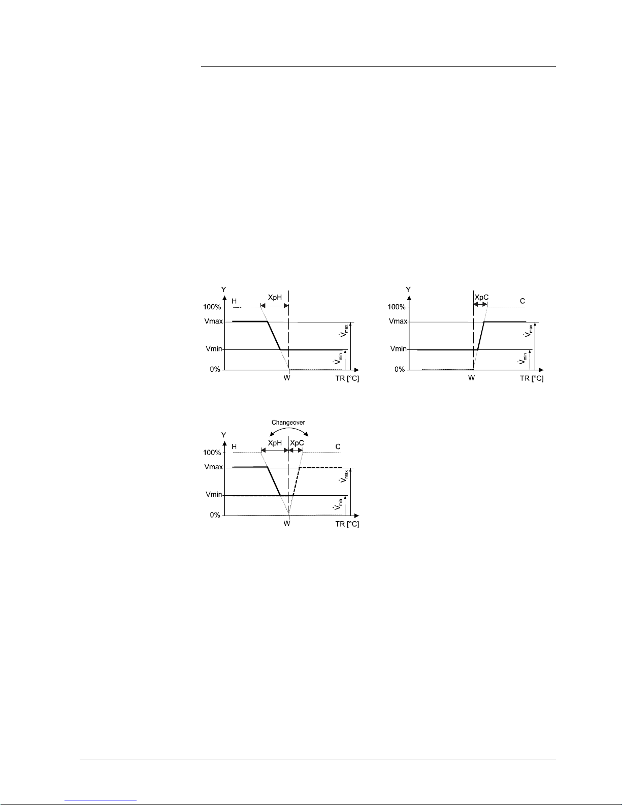
The diagrams below show the control sequence for modulating PI control.
Heating only (P01 = 0) Cooling only (P01 = 1)
Changeover (P01 = 2, 3)
T[°C] Room temperature XpH Proportional band “Heating”
w Room temperature setpoint XpC Proportional band “Cooling”
Y Control command “Actuator” Vmin Min. limitation for output
Vmax Max. limit ation for outpu t
The diagrams show the PI controller’s proportional part only.
Setting the sequence and the control outputs
Refer to section 3.4, section 3.6.1, and section 3.7.
Note:
Page 30

30 / 68
Siemens RDU341 Basic Documentation CE1P3172en
Building Technologies 2015-06-08
3.6.5 Single-duct with electric heater
General rule: In case of insufficient air flow, the thermostat cannot protect the
electric heater against overtemperature. Therefore the electric heater MUST
feature a separate safety device (thermal cutout).
On single-duct applications with electric heater, the thermostat controls a valve plus
an auxiliary electric heater. Parameter P01 is not available.
The output signal for the air flow can be limited to a minimum and maximum value
if required using parameters P63 and P64. With application " Single-duct with
electric heater", the min. value of P63 is overridden, so that the air flow never drops
below 10 % while the electric heater is ON.
The air flow starts to rise depending on the acquired room temperature, the current
supply air temperature (if available) and the setpoint.
The electric heater receives an ON command when the acquired room temperature
drops below setpoint (= setpoint for electric heater).
Remote enabling / disabling of the electric heater is possible via input X1 or X2 for
tariff regulations, energy savings, etc.
Input X1 or X2 must be commissioned acc ordingly (parameters P38, P40).
See section 3.8.
The electric heater can also be enabled / disabl ed via bus.
If “Enable electric heater” input is used via bus, then the function must not be
assigned to a local input X1 or X2.
On start-up of the controller and if the primary controller sends the information that
the primary f an i s off, the t hermostat disables the electric heat er, see section
3.10.9.
To avoid overheating of an electric heater when switched off, the air fl ow signal of
Vmin must be maintained for a preset "fan overrun time" (P54, factory setting
60sec).
In conjunction with a Synco primary controll er it will be assured that the primary fan
keeps running during the fan overrun time.
See also section 3.10.10.
Caution
Electric heating, active in
cooling mode
Digital input “Enable
electric heater”
KNX
R
Enable electric heater
Note
"Fan overrun tim e"
Page 31
31 / 68
Siemens RDU341 Basic Documentation CE1P3172en
Building Technologies 2015-06-08
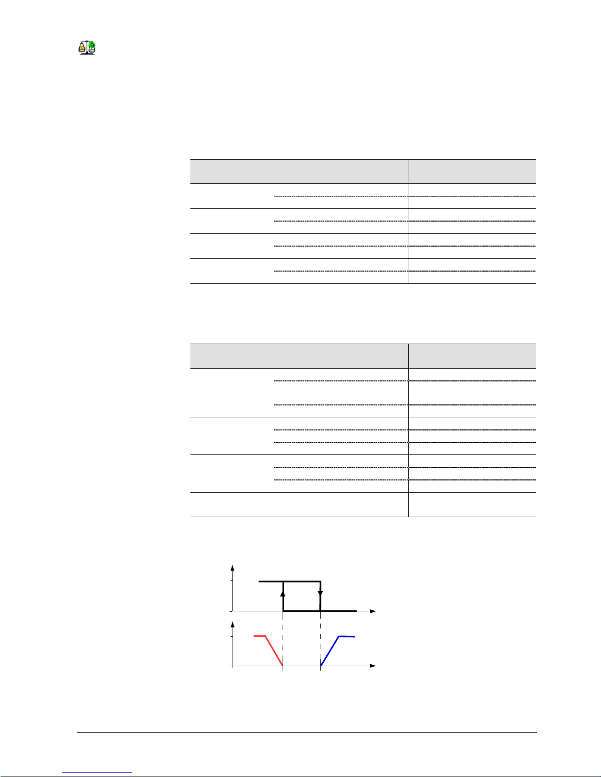
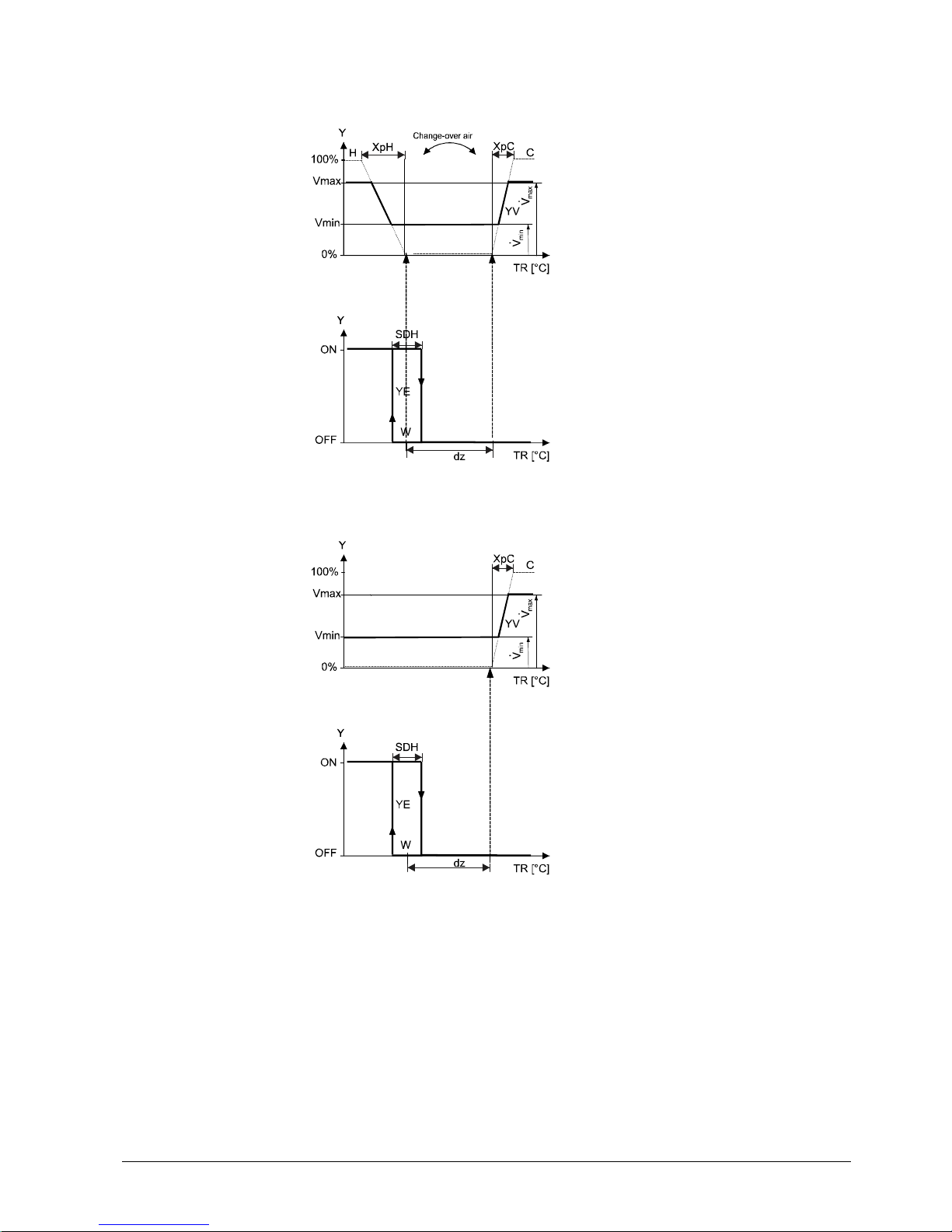
Sequences
ON/OFF electri c heater
Without a valid bus signal for changeover air, the air volume is only increased for
cooling:
Y Output signal
TR Room temperature
W Effective setpoint Comfort
H Heating sequence
C Cooling sequence
YV Volume flow rate
YE Electric heater
XpH Proportional band heating
XpC Proportional band cooling
Vmin Minimum volume output
Vmax Maximum volume output
The diagrams only show the PI thermostat’s proportional part.
Setting the sequence and the control outputs
Refer to section 3.4, section 3.6.1, and section 3.7.
Note:
Page 32
32 / 68
Siemens RDU341 Basic Documentation CE1P3172en
Building Technologies 2015-06-08
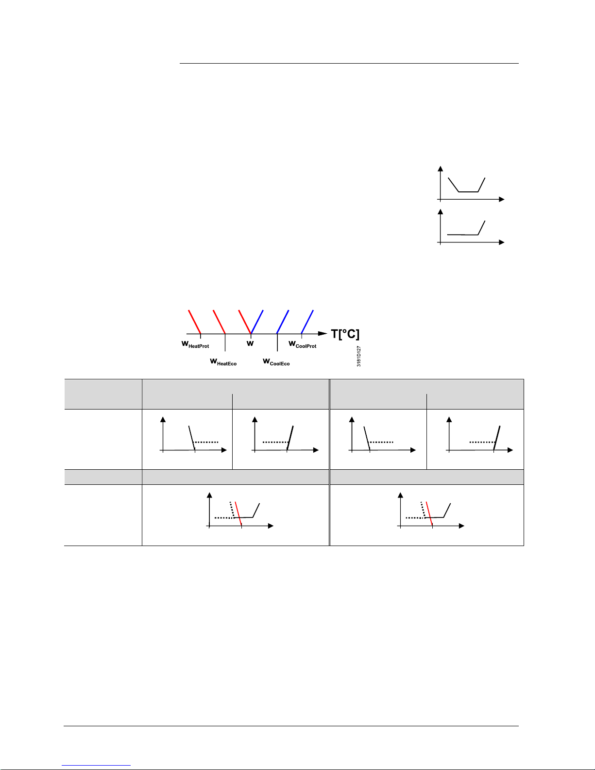
3.6.6 Setpoints and sequences
· Comf ort setpoint (W) is in the currently active heating or cooling sequence
· Comf ort setpoint (W) is in the heating sequence
· If the supply air temperature is available (via KNX), the air
flow may also increase when t he room temperature is
below the heating setpoi nt
· If no supply air temperature is available, sequence for air
flow control i s Cooli ng only
The setpoints for Economy and Protection mode are below the Comfort setpoints
(heating) and above the Comfort setpoints (cooling).
They can be set via parameters P11, P12 (Economy mode) and P65, P66
(Protection mode). .
Comfort mode
Economy / Protection mode
Application
Heating Cooling
Heating Cooling
Single duct
Heating and Cooling Heating and Cooling
Single duct with
el. heate
W = setpoint in Comfort mode
W
HeatEco/Prot
= setpoint heating in Economy or Protection mode
W
CoolEco/Prot
= setpoint cooling in Economy or Protection mode
Y = air / water sequence
T = room temperature
The dead zone can be adjusted via parameter P33.
Single duct / single
duct with heating /
cooling coil
Single d uct with el.
heater / radiator / floor
heating
Changeover air
Economy, Protection
Y
T
W
H
eatEco/P
rot
Y
T
W
Y
T
W
CoolEco/P
rot
Y
T
W
H
eatEco/P
rot
Y
T
W
Y
T
W
Page 33

33 / 68
Siemens RDU341 Basic Documentation CE1P3172en
Building Technologies 2015-06-08
3.7 Control outputs
3.7.1 Overview
Different control output signals are availabl e. They need to be defined during
commissioning (see below).
Control output
Product no.
ON/OFF 3-position DC 0…10 V
RDU341 Y21 -- Y10
The demand calculated by the PI control from the current room temperature and
setpoint is provided to the damper actuator as a continuous DC 0...10 V signal via
output Y10.
The electric heater receives an ON command via the auxiliary heating control
output Y21:
1. When the acquired room temperature is below “setpoint for electric heater”.
2. When the electric heater has been switched off for more than 1 minute.
The OFF command for the electric heater is output:
1. When the acquired room temperature is above the setpoint (electric heater).
2. When the electric heater has been switched on for more than 1 minute.
A safety thermostat (to prevent overheating) must be provided externally.
3.7.2 Control outputs configuration (setting via DIP switches
or tool)
Use DIP switch #3 on the inner side of the front panel to commission the signal
type of Y10 prior to snapping it to the base.
DIP switch number 3
DC 0…10 V output signal normal (factory setting) OFF
DC 0…10 V output signal i nv erted (DC 10...0 V) ON
If the application is configured via tool (DIP switches #1 and #2 = OFF), then the
signal type of Y10 must also be configured via tool.
Note: During startup, the controller reloads the c ontrol parameter factory settings
after each DIP switch settings change.
Overview of control
outputs
DC 0..10 V control
signal
Electric heater control
signal
(2-position)
Caution
Page 34
34 / 68
Siemens RDU341 Basic Documentation CE1P3172en
Building Technologies 2015-06-08
3.8 Multifunctional input, digital input
The thermostat has 2 multifunctional inputs X1 and X2
An NTC type sensor like the QAH11.1 (AI, analog input) or a switch (DI, digital
input) can be connected to the input terminals. The functionality of the inputs can
be configured via parameters P38 + P39 for X1, P40 + P41 for X2.
The current temperature or state of the inputs X1/X2 is available on bus for
monitoring purposes.
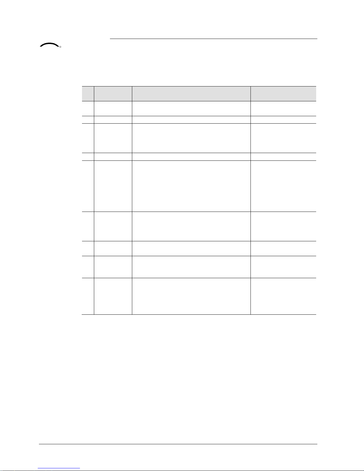
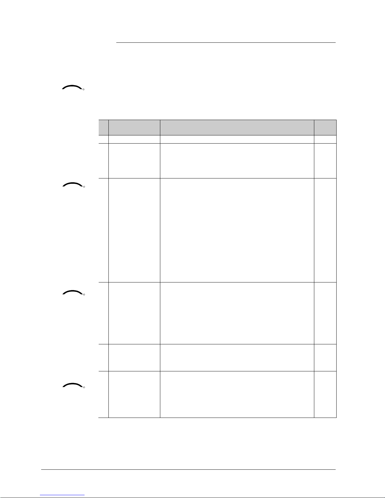
The parameters can be set to the following values:
# Function of
input
Description Type
X1/X2
0 Not used No function. -1 External / return
air temperature
Sensor input for external room temperature sensor or
return air tem perature sensor to acquire the current
room temperature, or floor heating temperature sensor
to limit the heating output.
AI
KNX
R
Supply air
temperature
2
Heating / cooling
changeover
Sensor input for “Automatic heating / cooling changeover” function.
A switch can also be connected rather than a sensor
(switch closed = cooling, see section 3.5).
With single-duct applications, the input changes over
the air sequence.
Heating / cooling changeover is also possibl e via bus.
In this case, the f unction must not be assigned to any
local input X1, X2, D1. See al so section 3.5.
Diagnostic value 0 ˚C is displayed for closed contact /
100 ˚C for open contact, if a switch is connected.
AI /
DI
KNX
R
Window
state
3
Operating mode
switchover
Digital input to switch over the operating mode to
Economy.
If the operating mode switchover contact is active, user
operations are i neffective and “OFF” is displayed.
Operating mode switchover is also possible via bus.
In this case, the f unction must not be assigned to any
local input X1, X2. See also section 3.2.
DI
4 Dew point
monitor
Digital input for a dew point sensor to detect
condensation. Cooling is stopped if condensation
occurs.
DI
KNX
R
Enable electric heater
5 Enable electric
heater
Digital input to enable / disable the electric heater via
remote control.
Enable electric heater is also possible via bus.
In this case, the f unction must not be assigned to any
local input X1, X2. See also section 3.6.
DI
KNX
R
Page 35

35 / 68
Siemens RDU341 Basic Documentation CE1P3172en
Building Technologies 2015-06-08
# Function of
input
Description Type
X1/X2
KNX
R
Fault
information
6 Fault Digital input to signal an external fault (example: dirty air
filter).
If the input is active, “ALx” is displayed and a fault is
sent on the bus. See also section 3.10.11.
(Alarm x, with x = 1 for X1, x = 2 for X 2).
Note: Fault displays have no impact on the thermostat's
operation. They merely represent a visual signal.
DI
KNX
R
X1, X2
(Digital)
7
Monitor input
(Digital)
Digital input to monitor the state of an external switch via
bus.
DI
KNX
R
X1, X2
(Temp.)
8
Monitor input
(Temperature)
Sensor input to m onitor the state of an external sensor
(e.g. QAH11.1) via bus.
AI
· Operational action can be changed between normally open (NO ) and normally
closed (NC) via parameter P39, P41.
· Each input X1, X2 m ust be configured with a different function (1…5).
Exception: 1 or 2 inputs can be configured as fault (6) or monitor input (7,8)
· X1 is factory-set to “O perating mode switchover” (3), X2 t o “External sensor”
(1)
For more detailed information, refer to section 3.4.
Page 36

36 / 68
Siemens RDU341 Basic Documentation CE1P3172en
Building Technologies 2015-06-08
3.9 Handling faults
When the room temperature is outside the measuring range, i.e. above 49 °C or
below 0 °C, the limiting temperatures blink, e.g. “0 °C” or “49 °C”.
In addition, the heating output is activated if the current setpoint is not set to “OFF”,
the thermostat is in heating mode and the temperature is below 0 °C.
For all other cases, no out put is activated.
The thermostat resumes Comfort mode after the temperature returns to within the
measuring range.
For fault status messages on the bu s, see section 3.10.11.
3.10 KNX communications
The RDU KNX thermostats support comm unications as per the KNX specificati on.
S-mode Standard mode; engineering via group addresses.
L TE mode Logical Tag Extended mode, for easy engineering,
is used in conjunction with Synco.
3.10.1 S-mode
This mode corresponds to KNX communications.
Connections are established via ETS by assigning communication objects to group
addresses.
3.10.2 LTE mode
LTE mode was specifically designed to simplify engineering. Unlike with S-mode,
there is no need to create the individual connections (group addresses) in the tool.
The devices autonomously establish connections.
To make this possible, the following circumstances are predefi ned:
· Ev ery device or subdevice is located within a zone
· Ev ery data point (input or output) is assigned to a zone
· Ev ery data point (input or output) has a precisely defined "name"
Whenever an output and an input with the same "name" are located in the same
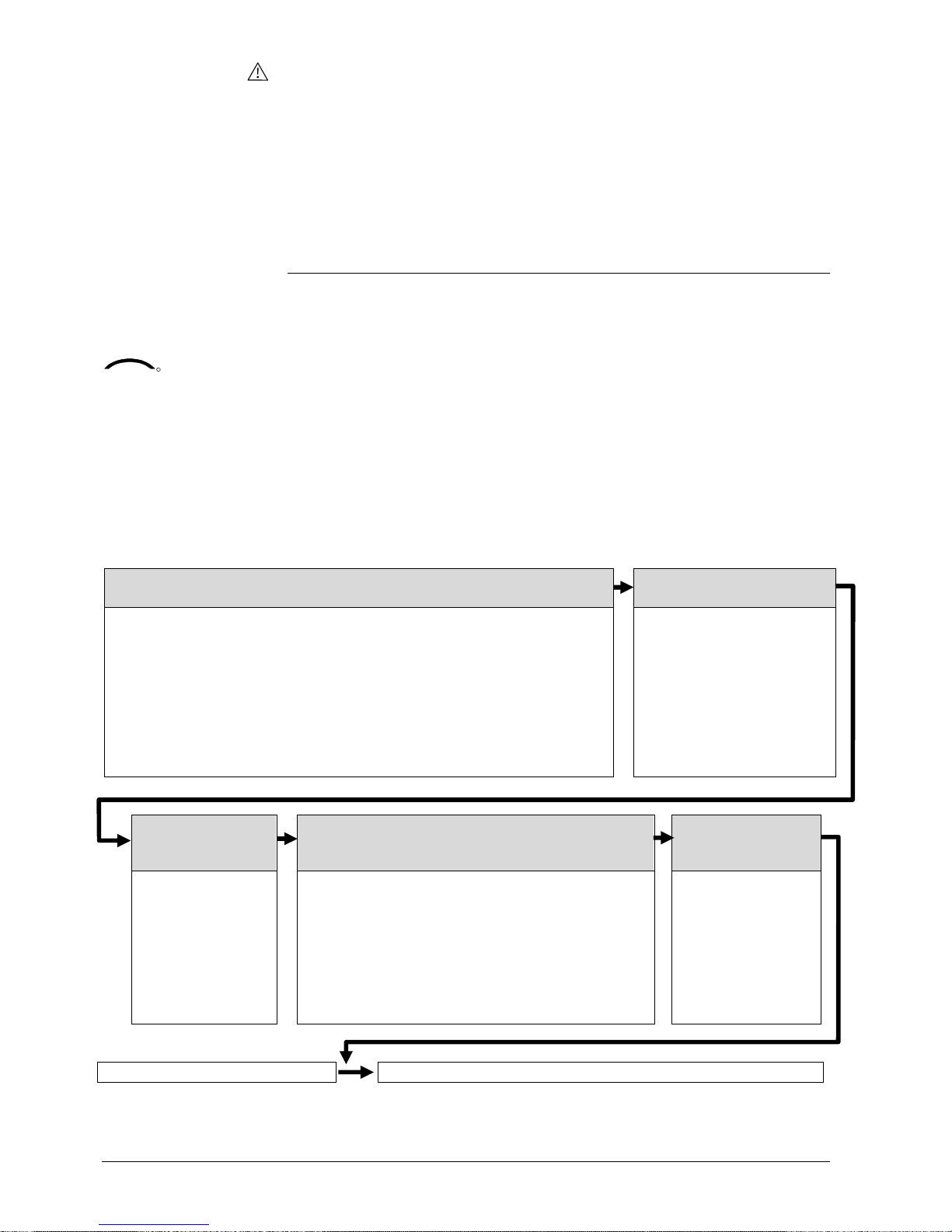
zone, a connection is established automatically, as shown in the following diagram.
Tempera ture out
of range
KNX
R
Definitions
Page 37

37 / 68
Siemens RDU341 Basic Documentation CE1P3172en
Building Technologies 2015-06-08
RDU
Air handling unit
Sensor
Outside temperature zone 1
Air distr zone 1
Geogr. zon e 2.5.1
Air d eman d
Outsi d e temper ature
3172Z02en
Outsi d e temper ature
Air demand
Outside temperature zone 1
Air distr zone 1
Time Switch
Operating mode Oper a ting mod e
Geogr. zone 2.5.1 or 2.1.1
Room temper ature
· For a detailed description of KNX (topology, bus supply, functi on and setting of
LTE zones, filter tables, etc.), see "Communication via the KNX bus for Synco
700, 900 and RXB/RXL, Basic Documentation" [6]
· LTE mode data points and settings are described in the Synco Application
Manual [12]
· To engineer and commission a specific system, use the Synco700 planning and
commissioning protocol (XLS table in HIT, [7])
3.10.3 Zone addressing in LTE mode (in conjunction with
Synco)
In cases where RDU KNX room thermostats are used in LTE mode (e.g. in
conjunction wit h Synco), zone addresses need to be allocated.
The following zone address must be defined together with the Synco devices at the
planning stage depending on the application.
Short description Facto ry setting Parameter
Geographical zone (apartment) --- (out of service) P82
Geographical zone (room) 1 P83
Air distribution zone --- (out of service) P87
Note: “Subzone” of “Geographical zone” is fix 1 (not adjustable)
The device will send and receive LTE communicati on signals only if the zone
address is valid (not OSV = out of service).
Engineering and
commissioning
Page 38

38 / 68
Siemens RDU341 Basic Documentation CE1P3172en
Building Technologies 2015-06-08
The zones to be defined are as f ollows:
Geographical zone
(space zone)
(Apartment . Room . Subzone)
Apartment = ---, 1...126
Room = ---, 1...63
Subzone = fix 1
Zone in which an RDU KNX thermostat is physically located. Other
room-specific devices may also be located in this zone.
Information ex changed in this zone is related specifi cally to the device
like operating mode, setpoints, room temperature, etc.
The designations "Apartment", "Room" and "Subzone" do not need to
be taken literally. For example, Apartment can be used to refer to a
group of rooms, floor or section of a building. ”Room", howev er, really
does refer to a room.
Subzone is not used for HVAC devices. It is more relevant to other
disciplines, such as lighting. Subzone is fix at “1” and not visible.
The time switch information is expected from the same zone where
the thermostat is located (Residential).
If no time switch information is received from the same zone, the
thermostat will use the information received from the same apartment
but with room “1“ A.1.1 (Office).
Example:
Commercial building
In a commercial building, the
time switch information is sent by
the RMB975 central control unit.
The zones are divi ded in so
called “Room groups” (e.g. 1...4),
where each “Room group” can
have an individual schedule. A
room thermostat in the same
“Room group” need to have the
same Apartment Address.
Legend:
D = device address (P81)
G = geographical zone (P82, P83)
(Apartment.Room. Subzone)
D: 001
G: 3.1.1
Meeting room
Office 1
Server room
Office 2
2
4
D: 002
G: 2.1.1
D: 003
G: 2.2.1
D: 10
G: 1.1.1
Corridor
D: 12
G: 1.3.1
D: 11
G: 1.2.1
D: 004
G: 4.1.1
1
2
3
3171z201
Air distribution zone
Zone = ---, 1...31
This Distribution zone is for air applications (VAV, CAV). Information
related specifically to the air handling system i s exchanged within this
zone (e.g. air demand). This zone also includes a Synco device to
process the information (e.g. RMU7xx).
Outs ide te m pe r a ture
zone
Zone = fix 1
Outside temperature received in outside temperature zone 1 will be /
can be displayed on the room thermostat when commissioned
accordingl y (parameter P07 = 2).
Page 39

39 / 68
Siemens RDU341 Basic Documentation CE1P3172en
Building Technologies 2015-06-08
3.10.4 Example of heating and cooling demand zone
The building is equipped with Synco controls on the generati on side and RDU /
RDG thermostats on the room side.
RMH760 RMH760 RMB795
Konnex TP1
RDG...RDU...
RDF...
T
T
T
T
1
2
P3171Z01
Heat requistion
Heat demand
Heat distr zone 1
Heat source
Controller 1 Controller 2
Controller 3
Controller 4 Controller 5 Controller 6
Controller 1 Controller 2 Controller 3 Controller 4 Controller 5 Controller 6
Heating circuit
fan coil
Fan coil
room A
VAV box
room B
Fan coil
room C
DHW heating
Heat demand
Heat demand
Heat demand
Heat demand
Heat requistion
Heat distr zone
source side: 1
Heat distr zone 2
Heat distr zone 2 Heat distr zone 2
Heat distr zone 2
Setting values
MV MV
T
T T
In the case of a typical application, the individual RDU / RDG room thermostats –
when used with the RMB975 central control unit – signal t heir heat demand directly
to the primary cont rol ler (in the above example to the RMH760).
(1) and (2) designate the numbers of the distribution zone.
· Thi s type of application can analogously be applied to refrigeration distribution
zones
· If no 2-pipe fan coil is used, heat and refrigeration demand signals are sent
simultaneously to the primary plant
Explanation relating to
the illustration
Notes:
Page 40

40 / 68
Siemens RDU341 Basic Documentation CE1P3172en
Building Technologies 2015-06-08
3.10.5 Send heartbeat and receive timeout
In a KNX network, S-m ode and LTE mode communication objects can be exc hanged
between individual devices. The Receive timeout defines the period of time within
which all the communication objects requested from a device must have been
received at least once. If a communication object i s not received within this period, a
predefined value is used.
Similarly, the Send heartbeat defines the period of time within which all the commu-
nication objects requested must be transmitted at least once.
Fixed times are specified as follows:
– Receiv e timeout: 31 minut es
– Send heartbeat: 15 minutes
Individual zones can also be disabled (out of service) via control parameter if they
are not being used. In disabl ed zones, the LTE signal will no longer be periodically
sent, and will theref ore reduce bus load.
3.10.6 Startup
The application is restarted after every reset, so that all the connected motorized
valve actuators are synchronized (see section 3.7).
After a reset, it takes up to 5 minutes for all the connected room thermostats to
restart. This is designed to avoid overloading the network when restarting. At the
same time, it reduces the load on the KNX network, as not all t hermostats transmit
data at the same time. The delay (T
WaitDevice
) is determined by the thermostat's
device address. After the delay, the device starts to send.
3.10.7 Heating demand
In S-mode, the current state signal of the control output (e. heater) is available.
3.10.8 Air demand
In conjunction with Synco, the air demand from each room is transmitted to the
BACS to provide the required air volume.
In S-mode, the curr ent state signal of the damper is available.
LTE mode / S-mode
Reducing the bus load
Startup response
Startup delay
KNX
R
Heating output primary
Cooling output primary
KNX
R
Control output VAV
Page 41

41 / 68
Siemens RDU341 Basic Documentation CE1P3172en
Building Technologies 2015-06-08
3.10.9 Electric heater interlock by supply air controller
(LTE mode only)
To avoid overheating of an electric heater, sufficient flow of supply air must be
guaranteed. The thermostat features the function “Interlock of el. heater via supply
air controller”, which is active when a supply air controller (e.g. Synco RMU7xx) is
used in the system. The supply fan controller sends the fan status (StatusSATC) to
the thermostat when the supply fan is running, after which the el heater is allowed
to turn on if there is a call for heat.
When the supply fan is not running, then the el. heater keeps turned off, even
though there is a dem and for heat.
The fan symbol is displayed, when the supply fan is on.
· El ectric heater enable via local input X1 / X2 or via KNX will override any release
by this interlock function and vise versa (last intervention wins).
· Af ter power-up of the thermostat the electric heater is completely disabled for at
least 5 minutes or until a supply air controller is detected. If no supply fan
controller is in the system, the el. heater is allowed to turn on if there is a
demand for heat.
· T he fan informati on is broadcast every 15 minutes or on change of value. If no
value is received any more, the thermostat will disable the interlock function after
a timeout of 31 minutes.
General rule: In case of insufficient air flow, the thermostat cannot protect the
electric heater against overtemperature. Therefore the electric heater MUST
feature a separate safety device (thermal cutout).
3.10.10 Primary fan ov errun af ter switching off the electric
heater
To avoid overheating of an electric heater after it has been switched off, the air flow
must be maintained for a while.
In conjunction with a supply air controller (e.g. Synco RMU7xx) this will be
automatically assured by exchanging the necessary information. The supply fan
controller wi ll only switch off the supply fan once all el. heaters are cooled off.
Note: The cool off time of the el. heater can be adjusted for each el . heater via
parameter "fan overr un time" (P54, factory setting 60sec).
General rule: In case of insufficient air flow, the thermostat cannot protect the
electric heater against overtemperature. Therefore the electric heater MUST
feature a separate safety device (thermal cutout).
Notes
Caution
Caution
Page 42
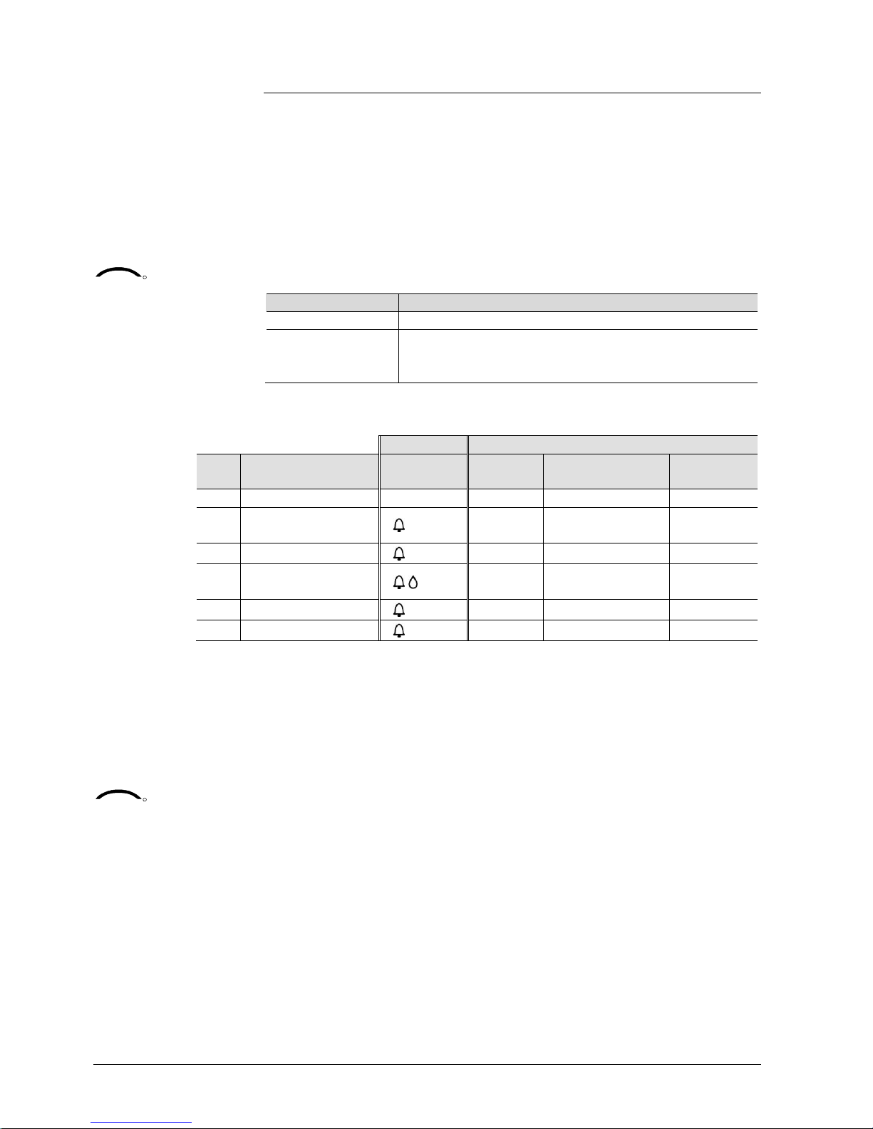
42 / 68
Siemens RDU341 Basic Documentation CE1P3172en
Building Technologies 2015-06-08
3.10.11 Fault function on KNX
If a fault occurs (e.g. digital fault input, dew point, communication configuration,
etc.) then a fault will be sent on the bus.
An RDU thermostat listens on the bus and sends its fault when the fault has the
highest alarm priority. This ensures that the management station does not miss any
alarms.
If alarms occur at the same time, the alarm with the highest priority will be first
displayed and sent on the bus.
Fault transmission is different in LTE mode and S-mode:
S-mode LTE mode
Fault state Alarm info (error code + internal information)
Fault information
(internal
information)
Alarm text (default text can be edited with ACS tool)
The table below shows the error code and default alarm texts.
Thermostat Fault information on bus
Prio Fault Display Error code Default fault text
Text
adjustable *)
- No fault --- 0 No fault
ü
1 Bus power supply**)
bus
5000 No bus power
supply
---
2 Device add ress error Addr 6001 >1 id device address --3 Condensation 4930 Condensation in the
room
ü
4 External fault input X1 AL1 9001 Fault input 1
ü
5 External fault input X2 AL2 9002 Fault input 2
ü
*) Default alarm texts are stored in the thermostat’s non-volatile memory and can
be adjusted using the ACS commissioning tool
**) Thi s error will not be sent on bus (because there is no bus!)
· Priority order is #1…5
· Ext ernal faults #4…5: If faults are active, the display will show AL1, AL2,
alternating. On the bus, only the fault with the highest priority will be sent
A supervisor alarm system may command the thermostat to stop sending f aults to
the bus via the communication object “Fault transmission” (disable / enable).
This has no impact on the local display of faults.
After a timeout of 48 hours, the sending of faults will automatically be enabled
again.
KNX
R
Priority of alarms
KNX
R
Fault transmi ssion
Page 43
43 / 68
Siemens RDU341 Basic Documentation CE1P3172en
Building Technologies 2015-06-08
3.10.12 Emergency control (LTE Mode only)
In case of smoke or fire the damper can be overri dden via KNX.
The necessary information is provided by the functi on block “HVAC Emergency
Mode”
The table below describes the behavior of the controll er output.
# Datapoint value Damper
0 Normal Normal operation
1 EmergPressure Fully open
2 EmergDepressure Fully closed
3 EmergPurge Fully open
4 EmergShutdown Fully closed
5 EmergFire Fully closed
Emergency signal s have highest priority and command the cont rol output
accordingly. Any ongoing function like fan-overrun etc. will be stopped immediately.
The priority is as follows:
1. Smoke (Emergency 1..4)
2. Fire (Emergency 5)
3. Fan overrun (Emergency 0 and el heater fan overrun function is active)
4. Normal operation (Emergency 0 and operation by operating mode button)
Page 44

44 / 68
Siemens RDU341 Basic Documentation CE1P3172en
Building Technologies 2015-06-08
3.11 Communication objects (S-mode)
3.11.1 Overview
Page Object # and name Thermostat Object # and name Page
12 1 System time
12 3 Time of day
12 38 Outside temperature 21 Room temperature 12
14 12 Room operating mode:
Time switch
1)
16 Room operating mode:
State
1)
13
14 7 Room operating mode:
Preselection
1)
24 Room temperature:
Current setpoint
21
13, 15,3420 Room operating mode:
Window state
32/33 X1 (temperature / digital) 35
20 22 Room temperature:
Comfort basic setpoint
34/35 X2 (temperature / digital) 35
20 23 Room temperature:
Comfort setpoint
25 Control output VAV 40
26 31 Application mode
26 Heating output primary
2)
40
34 20 Enable electric heater
23, 34 30 Supply air temperature
42 6 Fault transmission 5 Fault state 24, 42
4 Fault information 24, 35,
42
Input communi catio n object
Output communication object
Input & output communication object
1) 8-bit and 1-bit object availa ble, selectable via paramet er in ETS
2) Availability depending on selected application / function
Page 45

45 / 68
Siemens RDU341 Basic Documentation CE1P3172en
Building Technologies 2015-06-08
3.11.2 Description of communication objects
Obj Object name Function Type/ length Flags
1 System time Time and
date
19.001
8 Byte
CWU
System time for display on the room t hermostat. See par ameter
P07 (3 or 4)
3 Time of day Time and
date
10.001
3 Byte
CWU
Another object for receiving the time of da y for display on the room
thermostat. See parameter P 07 (3 or 4)
4 Fault information Alarm
Info
219.001
6 Byte
CT
Common alarm output. If an alarm occurs, the alarm n umber is
transmitted
5 Fault state Faulty /
normal
1.005
1 bit
CT
Common alarm output. If an al arm occurs, the alar m f lag is set
6 Fault
transmi ssion
Enable /
disable
1.003
1 bit
CWU
A supervisor alarm system can disable th e broadcasting of alarms
by the devices. This has no impact on the local display of alarms.
After a tim eout of 48 hours, the sending of faults will automatically
be enabled again.
7 Room operating
mode:
Preselection
Auto
Comfort
PreComf.
Economy
Protection
20.102
1 Byte
CWTU
Controls the room operating mode selecti on of the thermostat vi a
bus.
The comm and can also be submitted as four 1-bit communication
objects (8...11). The last interaction wins – either from local
operating mode button or via b us.
Note: The thermostat will transform Precomfort either into
Economy or Comfort (selectable via P88).
8
9
10
11
Operating mode:
Preselection
Auto
Comf
Eco
Prot
Trigger 1.017
1 bit
CW
Switch room operat ing mode to ei ther Auto, Comf ort , Economy or
Protection.
The last interact ion wins – either from the local operating mode
button or via bus.
12 Room operating
mode: Time
switch
Comfort
Economy
PreComf.
Protection
20.102
1 Byte
CWU
This inf or mation is provided by a c entral time switch or a
supervisor and defines the actual HVAC operating mode.
The comm and can also be submitted via three 1-bit
communication obj ects ( 13...15).
Protection has the highest priority and cannot be overridden.
Note: The thermostat will transform Precomfort either into
Economy or Comfort (selectable P88).
13
14
15
Time switch
Comfort
Economy
Protection
Trigger 1.017
1 bit
CW
Switch the HVAC mode to either Comfort, Ec onomy or Pr otection
mode.
Obj Object name Function Type/ length Flags
16 Room operating
mode: State
Comfort
Economy
Protection
20.102
1 Byte
CRT
Effective room oper ating mode used by the thermostat
(considering time switch, user selection, window contact, etc.) This
state information is available via one 8-b it enumerati on or three 1bit communication objects (17...19). Note: The thermostat does not
support Precomf ort.
17
18
19
Room operating
mode:
State Comfort
State Economy
State Protection
ON
OFF
1.002
1 bit
CT
Corres ponding communication object sends "True"
20 Window state Open
Closed
1.019
1 bit
CWU
The thermostat is set to Econom y mode if value “1” (open) is
received. It switches back to the previous mod e when the valu e is
“0” (closed).
"Window state" is sent e.g by a KNX switc h or a KNX pr esence
detect or. It has the same effect as th e local operating mod e
switchover contact X1, X2 (param eter P38, P40).
Only one input source must be used, either local input X 1/X2 or
KNX bus.
21 Room temperature Temp.
value
9.001
2 Bytes
CRT
The valu e of the room t em peratur e measured vi a b uilt-in or
extern al sensor is available vi a this communication object.
22 Room tempera
ture:
Comfort basic
setpoint
Temp.
value
9.001
2 Bytes
CWU
If function "Temporary setpoint" is enabled via parameter P69, then
after an operating mode chang e, the setpoint adjustments mad e by
the user and via comm unication object 23 wil l be dismissed and
the thermostat will be reset to the Comfort bas ic setpoint.
Note: Setp oints that have been changed via the local HMI may be
overwri tten durin g a system startup from a central master
controller, e.g.RMB795.
The Comfort basic setpoint is stored in EEPRO M (see section
3.3.2).
à
The service life of the EEPROM depends on the number
of write cycles. Never write this communication object cyclically!
23
Room temperature:
Comfort setpoint
Temp.
value
9.001
2 Bytes
CWTU
Communication object used to shift the setp oint used by the
thermostat (see section 3.3.2). Same priority as local setpoint shift
on the thermostat. The last intervention wins.
Note: The Comfort basic setpoint (object 22) will not be changed.
24
Room temperature:
Current setpoint
Temp.
value
9.001
2 Bytes
CRT
Current setpoint, including shift, compensation, etc., used by the
thermostat for temperature control
25 Control output
VAV
0…100% 5.001
8 bit
CRT
Indicates the position of the air dam per. E.g. single duct
26 Heating output
primary
0…100% 5.001
8 bit
CRT
Indicates the position of the heating actuator of the auxiliary
heating. E.g. single duct with electric heater application : Output of
the electric h eat er.
Page 46

46 / 68
Siemens RDU341 Basic documentation CE1P31 72en
Building Technologies 2015-06-08
Obj Object name Function Type/ length Flags
28 Enable electric
heater
Enable /
disable
1.003
1 bit
CWU
An elect ric heater can be disabled with this communic ation obj ect
(e.g. to meet tariff r egulations).
The same function is also available via local multifunctional inp ut
X1/X2 (parameter P38, P40).
Only one input source must be used, either local input X1/X2or
KNX bus.
30 Supply air
temperature
Temp.
value
9.001
2 Byte
CWU
The suppl y air temperature sent by the supply air c ontroller
indicat es whether cold or hot air is supplied (for VAV changeover).
The controller d etermines the necess ity to open or close th e air
damper according to the supply air temperature, the room temperature setpoint, and the current room temperature.
The same function is also available via local multifunctional inp ut
X1/ D1 (parameter P38, P42).
Only one input source must be used, either local input X1/X2/D 1or
KNX bus.
31 Application mode HVAC
control
mode
20.105
8 bit
CWU
0 Auto (default) Heat ing and/or cooling
1 Heat Heating only
2 Morning warmup* Heating on l y
3 Cool Cooling only
4 Night purge Open damper fully
5 Precool* C oolin g only
6 OFF Neither heating nor cooling
8 Emergency heat* Heating only
9 Fan only Open damper fully (= night purge)
* Funct ion handled like Heat (1) or Cool (3 )
Obj Object name Function Type/ length Flags
3234X1: Temperature
X2: Temperature
Temp.
value
9.001
2 Byte
CRT
Indic ates the valu es of the t emperature sensors connect ed to the
local inputs X1 / X2
3335X1: Digital
X2: Digital
ON
OFF
1.001
1 bit
CRT
Indic ates the status of the digital inputs (adjusted by parameters
P39/P41) inc luding c ons idering of operating action
38 Outside
temper ature
Temp.
value
9.001
2 Byte
CWU
The outside temperature m easured by a KNX sensor can be
displayed on the thermostat, if parameter P07 "Additional user
informat ion” is set = 2 (outside temperature).
Page 47

47 / 68
Siemens RDU341 Basic Documentation CE1P3172en
Building Technologies 2015-06-08
3.12 Control parameters
A number of control parameters can be readjusted to optimize control performance.
This can be done on the thermostat via HMI or via commissioning / operating tool.
These parameters can also be set duri ng operation without opening the unit.
In the event of a power failure, all control parameter settings are retained.
The control parameters are assigned to 2 levels:
· “Service l evel”, and
· “Expert level” including communications, diagnostics and test
The “Service lev el” contains a small set of parameters to set up the thermostat for
the HVAC system and to adjust the user interface. These parameters can be
adjusted any time.
Change parameters at the “Expert level” carefully, as they impact the thermostat’s
control performance and functionality.
3.12.1 Parameter setting via local HMI
1. Press buttons + and – simultaneously for 3 seconds. Release and press button
+ again for 3 seconds within 2 seconds. The display shows “P01”.
Continue with step 2.
1. Press buttons + and – simultaneously for 3 seconds. Release and press button –
again for 3 seconds within 2 seconds. The display shows “P01” and "service".
2. Repeat edly press the + or – button to select the required parameter.
P01
P02 P08 P14
+- +
- -
+
3171z99
End
-
+
P13
+-
3. Press + and – simultaneously. The current value of the selected parameter
begins to flash, allowing you to change the value by repeatedly pressing + or –.
4. The next parameter is displayed when you press + and – again simultaneously.
5. Repeat steps 2 to 4 to display and change additional parameters.
6. Press + or – until “End” is displayed, and then press + and – simultaneously to
save the change and exit parameter entry mode.
The factory setting for the control parameters can be reloaded via parameter P71,
by changing the value to “ON”, and confirming by pressing buttons + and –
simultaneously. The display shows “8888” during reload.
Enter only “Service”
level
Enter “Service” and
“Expert” level
Adjust parameters
Reset parameters
Page 48

48 / 68
Siemens RDU341 Basic Documentation CE1P3172en
Building Technologies 2015-06-08
3.12.2 Parameter setting / download via tool
Control parameters can be adjusted via bus either by parameter download during
commissioning or during normal operation with a tool like ACS.
With the ACS tool, the parameters can be changed…
– during commissioning via parameter download (all parameters)
– during normal operation via Popcard (most of the parameters)
Most parameters can be changed during normal operation using the OZW772 web
server or the RMZ792-B bus operator unit.
Only the parameters for device address can be downloaded via ETS3 Professional.
This is to simplify and avoid a conflict.
It allows you to further engineer communication objects of an RDU prev iously
commissioned vial local HMI or ACS (assigning communication objects to group
addresses).
· The basic application can only be changed via parameter download with ACS.
· The RDU KNX thermostats require version ETS3f or higher / ACS version 5.11
or higher.
Connecting a KNX commissioning / operating tool to the RDU is described in
section 4.2.
ACS
OZW772 Web server,
RMZ792-B
bus oper a tor
unit
ETS
Notes:
Connecting a KNX tool
Page 49

49 / 68
Siemens RDU341 Basic Documentation CE1P3172en
Building Technologies 2015-06-08
3.12.3 Parameters of the "Service level"
Parameter
Name Factory setting Range
Service level
P01 Control sequence 1 0 = Heating only
1 = Cooling only
2 = H/C changeover manual
3 = H/C changeover auto
P02 Operation via room op selector 1 1 = Auto - Protection
2 = Auto - Comfort - Economy -
Protection
P04 Unit 0 0 = °C
1 = °F
P05 Measured value correction 0 K – 3 ... 3 K
P06 Standard display 0 0 = Room temperature
1 = Setpoint
P07 Additional display information 0 0 = --- (No display)
1 = °C and °F
2 = Outside temperature (via bus)
3 = Time of day (12h) (via bus)
4 = Time of day (24h) (via bus)
P08 Comfort basic setpoint 21 °C 5 ... 40 °C
P09 Comfort setpoint minimum 5 °C 5 ... 40 °C
P10 Comfort setpoint maximum 35 °C 5 ... 40 °C
P11 Economy heating setpoint 15 °C OFF, 5 ... WCoolEco;
WCoolEco = 40 °C max
P12 Economy cooling setpoint 30 °C OFF, WHeatEco ... 40 °C;
WHeatEco = 5C min
P14 Button lock 0 0 = Unlocked
1 = Auto l ock
2 = Manual lock
Parameter display depends on selected application and function.
Note:
Page 50
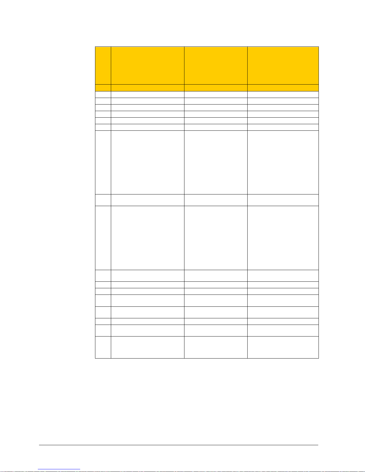
50 / 68
Siemens RDU341 Basic Documentation CE1P3172en
Building Technologies 2015-06-08
3.12.4 Parameters of the "Expert level
with diagnostics and test"
Parameter
Name Factory setting Range
Expert level
P30 Heat P-band Xp / switching diff 2 K 0.5 … 6 K
P31 Cool P-band Xp / switching diff 1 K 0.5 … 6 K
P33 Dead zone Comfort mode 2 K 0.5 … 5 K
P35 Integral action time Tn 5 min 0…10 min
P36 H/C ch'over swi point cooling 16 °C 10…25 °C
P37 H/C ch'over swi point heating 28 °C 27…40 °C
P38 Input X1 3 = Op m ode contact 0 = --- (no function)
1 = Room temp ext. s ensor /
Return air temp (AI)
2 = H/C changeover (AI/DI)
3 = Operating mode contact (DI)
4 = Dew point sensor (DI)
5 = Enabl e electric heater (DI)
6 = Fault input (DI)
7 = Monitor input (Digital)
8 = Monitor input (Temp)
9 = Supply air sensor (AI)
10 = Presence detec tor (DI)
P39 Normal position input X1 0 (N.O.) 0 = Normally open / Open
1 = Normally closed / Close
P40 Input X2 1 = Ext. sensor 0 = --- (no function)
1 = Room temp ext. s ensor /
Return air temp (AI)
2 = H/C changeover (AI/DI)
3 = Operating mode contact (DI)
4 = Dew point sensor (DI)
5 = Enabl e electric heater (DI)
6 = Fault input (DI)
7 = Monitor input (Digital)
8 = Monitor input (Temp)
9 = Supply air sensor (AI)
10 = Presence detec tor (DI)
P41 Normal position input X2 0 (N.O.) 0 = Normally open / Open
1 = Normally closed / Close
P63 Supply air limit value min 0% 0…P64 (%)
P64 Supply air limit value max 100% P63...100 (%)
P65 Protection heating setpoint 8 °C O FF, 5…WCoolPr ot;
WCoolPr ot = 40 °C m ax
P66 Protection cooling setpoint OFF OFF, WHeatProt… 40;
WHeatProt = 5°C mi n
P68 Temporary Comfort mode 0 (= OFF) 0...360 mi n
P69 Temporary Comfort setpoint OFF OFF = Disabled
ON = Enabled
P71 Restore factory setting OFF OFF = Disabled
ON = Reload start
“8888” is displayed for 3s during
reload process
Page 51

51 / 68
Siemens RDU341 Basic Documentation CE1P3172en
Building Technologies 2015-06-08
Parameter
Name Factory setting Range
Communications
P81 Device address
1)
255 1…255
P82 Geographical zone (apartment)2) --- ---, 1...126
P83 Geographical zone (room)
2)
1 ---, 1...63
P87 Air distribution zone --- ---, 1...31
P88 Transformation Precomfort 0 0 = Economy
1 = Comfort
1)
Ph ysical address = Area.L ine.Devic eAddr ess. Factory setting for Area = 0, Line = 2.
Can be changed by special management service e.g. from line c oupler or via ACS commissioning tool.
2)
Type = geographic al zone A.R.S. In RDG RDU sub zone = f ixed valu e 1
Parameter
Name Range
Diagnostics & test
d01 Applic ati on nu m b er NONE = (No application)
Sd = Single duct
SdEL = Single duct wit h electric heater
d02 X1 state 0 = Not activated (for DI)
1 = Activat ed (DI)
0…49 °C = Cu rrent temp. value (f or AI)
00
= H/C Input shorted
100
= H/C Input open
d03 X2 state 0 = Not activated (for DI)
1 = Activat ed (DI)
0…49 °C = Cu rrent temp. value (f or AI)
00
= H/C Input shorted
100 = H/C Input open
Page 52
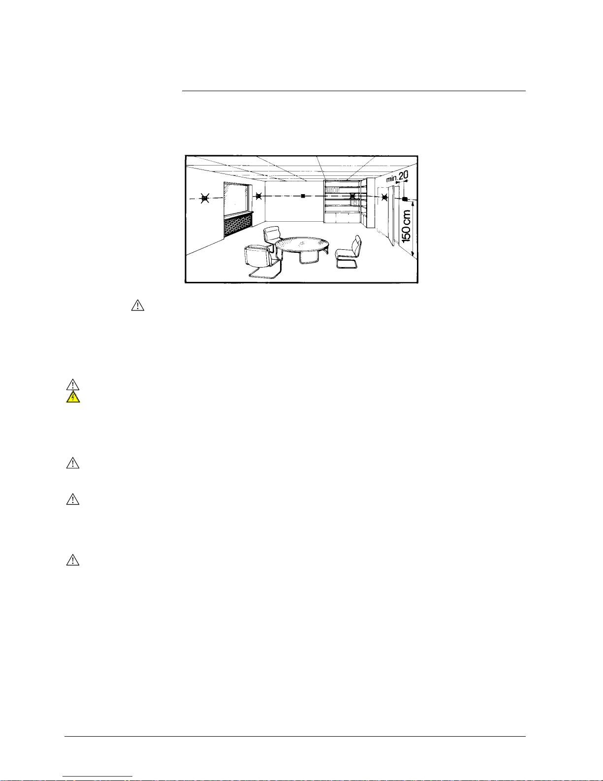
52 / 68
Siemens RDU341 Basic Documentation CE1P3172en
Building Technologies 2015-06-08
4. Handling
4.1 Mounting and installation
Mount the room thermostat on a recessed square conduit box with 60.3 mm fixed
centers. Do not mount on a wall in niches or bookshelves, behind curtains, above
or near heat sources, or exposed to direct solar radiation. Mount about 1.5 m
above the floor.
Mounting
· Mount t he room thermostat in a clean, dry indoor place without direct airflow
from a heating / cooling device, and not exposed to dripping or splash water
· In case of limited space in the conduit box, use mounting bracket ARG70.3 to
increase the headroom by 10 mm
Wiring
See Mounting Instructions M3172 [3] enclosed with the thermostat.
· Com ply with local regulations to wire, protect and earth the controller.
Warning!
No internal line protection for supply lines to external consumers (Y10, Y21)
Risk of fire and injury due to short-circuits!
· Adapt the line diameters as per local regulations to the rated value of the
installed ov ercurr ent protection device.
· The AC 230 V mains cable and the AC 24 V supply line must have an external
circuit breaker with a rated current of no more than 10 A. For US installations
use Class 2 rated power supplies.
· Isol ate the cables of SELV inputs X1-M/X2-M for 230 V if the conduit box carries
AC 230 V mains voltage.
· Input s X1-M or X2-M of different units (e.g. summer/winter switch) may be
connected in parallel with an external switch. Consider overall maximum
contact sensing current for switch rati ng.
· Isol ate the cables of KNX communication input CE+ / CE- for 230 V if the
conduit box carries AC 230 V mains voltage.
· Disconnect from supply before opening the cover.
Page 53

53 / 68
Siemens RDU341 Basic Documentation CE1P3172en
Building Technologies 2015-06-08
4.2 Commissioning
The room thermostats are delivered with a fixed set of applications.
Select and activate the relevant applicati on during commissioning using one of the
following tool s:
– Local DIP switch and HMI
– Synco ACS
– ETS
Set the DIP switches before snapping the front panel to the mounting plate, if you
want to select an application via DIP switches.
All DIP switches need to be set to “OFF” (remote configuration), if you want to
select an application via commissioning tool.
After power is appli ed, the thermostat resets and all LCD segments flash, indicating
that the reset was correct. After the reset, which takes about 3 seconds, the
thermostat is ready f or commissioning by qualified HVAC staff.
If all DIP switches are OFF, the display reads "NONE" to indicate that appli cation
commissioning via a tool is required.
Each time the application is changed, the thermostat reloads the factory setting for
all control parameters, except for KNX device and zone addresses!
Connect the Synco ACS or ETS tools to the KNX bus cable at any point for
commissioning:
N1
3172A04
.
.
KNX
ETS
RS232
Siemens
N148
UP146
UP152
ETS/ACS
Siemens
OCI700
OCI702
G
G0 Y21 Y10 G0
X1 M X2
L
CE+ CE-
ACS and ETS require an interface:
– RS232 KNX interface (e.g. Siemens N148 / UP146 / UP152)
– OCI700, OCI702 interface
An external KNX bus power supply is required if an RDU is connected directly to a
tool (ACS or ETS) via KNX interface.
Applications
DIP switches
Note:
Connect tool
Note:
Page 54

54 / 68
Siemens RDU341 Basic Documentation CE1P3172en
Building Technologies 2015-06-08
The thermostat's control parameters can be set to ensure optimum perf ormance of
the entire system.
The parameters can be adjusted using
– Local HMI
– Synco ACS
– ETS
The control parameters of the thermostat can be set to ensure optimum
performance of the entire system (see section 3.12).
· The control sequence may need to be set via parameter P01 depending on the
application. The factory setting is as follows:
Application Factory setting P01
Single duct 1 = cooling only
Single duct wit h el. heater Not adjustable
· Recal ibrat e the temperature sensor if the room temperature displayed on the
thermostat does not match the room temperature measured (after min. 1 hour of
operation). To do this, change parameter P05
· W e recommend to review the setpoints and setpoint ranges (parameters
P08…P12) and change them as needed to achieve maximum comfort and save
energy
The programming mode helps identify the thermostat in the KNX network during
commissioning.
Press buttons “operating mode”
and “+” simultaneously for 6 sec to activate
programming mode, which is indicated on the display with "PrOg".
Programming mode remains active until thermostat identification is complete.
Use ETS to assign the KNX group addresses of the thermostat's communication
objects.
Each device has a unique KNX serial number inside the front panel.
An additional sticker with the same KNX serial number is enclosed in the
packaging box. This sticker is intended for installers for documentation purposes.
Control parameters
Control sequence
Calibrat e sensor
Setpoint and range
limitation
Programming mode
Ass ign KNX grou p
addresses
KNX serial number
Page 55

55 / 68
Siemens RDU341 Basic Documentation CE1P3172en
Building Technologies 2015-06-08
4.3 Operation
See also Operating I nstructions B3172 [2] enclosed with the thermostat.
Layout
1 Operating mode selector / Protection
2 Adjust setpoint and control parameters
User action Effect, description
Normal operation Actual operating mode and state are
indicated by symbols
Press any button
(thermostat in norm al operation)
Backlit LCD turns on and… (see bel ow for
further acti on)
After the last operation and a timeout of 20
seconds, the LCD backlight turns off
Press left button Change operating mode
Press left button ( P01 = 2) Toggle between heating and cooling
Press left button while "Operating
mode" via bus is Economy
Activate "Extend Comfort mode"
(for details, see page 16)
Press left button >5 seconds Activate / deactivate button lock
Press + or – Adjusts the Comfort room t em perature
setpoint .
Thermostat changes to Comfort mode
Press + and – >3 seconds, release,
then press + agai n >3 seconds
Go to parameter setting mode “Service
level”
Press + and – >3 seconds, release,
then press – again >3 seconds
Go to parameter setting mode “Expert
level”, diagnosti cs and test
Press operating m ode button and “+”
simultaneously for 6 seconds
Enter (KNX) programming mode
Button ope r a tion
1
2
Page 56

56 / 68
Siemens RDU341 Basic Documentation CE1P3172en
Building Technologies 2015-06-08
3 Heating/cooling mode
Cooling
Heating,
Electric heater active
4 Additional user information, like outdoor
temperature
or time of day from
KNX bus
1 Operating mode
Protection
Comfort
Economy
Auto T imer according to schedule
(via KNX)
2 Displays room temperature, setpoints
and control parameters.
Symbol indicates the current room
temperature
5 Indicates fault or reminder
6
Condensation i n room
(dew point sensor active)
7 Temporary comfort prolong activ e
8
Primary fan is active (only sup-
ported with Synco700 primary controller)
9
Button lock active
10
Weekday 1…7 from KNX bus
(1 = Monday / 7 = Sunday)
4.4 Remote operation
The RDG thermostats can be operated from a remote location using a OZW772 /
OZW775 web server, a RMZ792-B bus operating unit or the ACS Operating tool.
4.5 Disposal
The devices are consi dered electronics devices for disposal in terms of European
Directive 2012/19/EU and may not be disposed of as domestic waste.
· Dispose of the device via t he channels provided for this purpose.
· Comply with all l ocal and currently applicable laws and regulations.
Display
1
2
3
4
5
8
7
6
9
10
Page 57

57 / 68
Siemens RDU341 Basic Documentation CE1P3172en
Building Technologies 2015-06-08
5. Supported KNX tools
5.1 ETS
ETS is an engineering tool. It is used to set up the communication of the RDU KNX
thermostat and assigns the communication object to group addresse s (S-mode).
Parameters are only used for choosing (making visible / hiding) the communication
objects.
This Manual does not describe how to operat e ETS and commission a device.
Refer to the KNX Manual for more details.
Setting RDU KNX parameters is only supported by ETS3f or higher.
5.1.1 Parameter settings in ETS
For setting the paramet ers, open the project and select a devi ce.
To start the parameter settings, select Edit, then Edit parameters.
· Param eters are only used to choose the communication objects
· The tool required is ETS version 3f or higher!
5.2 ACS tool
With the ACS tools, the RDU KNX thermostats can be commissioned (physical
address, application, parameters). They can be operated or monitored via bus
during normal operat ion.
This Manual does not descri be how the physical address is defined. Also, it only
gives a brief overview of the main functionality of ACS.
For more information, refer to the ACS online help.
Setting RDU KNX parameters is only supported by ACS Version 5.11 or
higher.
ETS
STOP
Note!
Notes:
ACS
STOP
Note!
Page 58
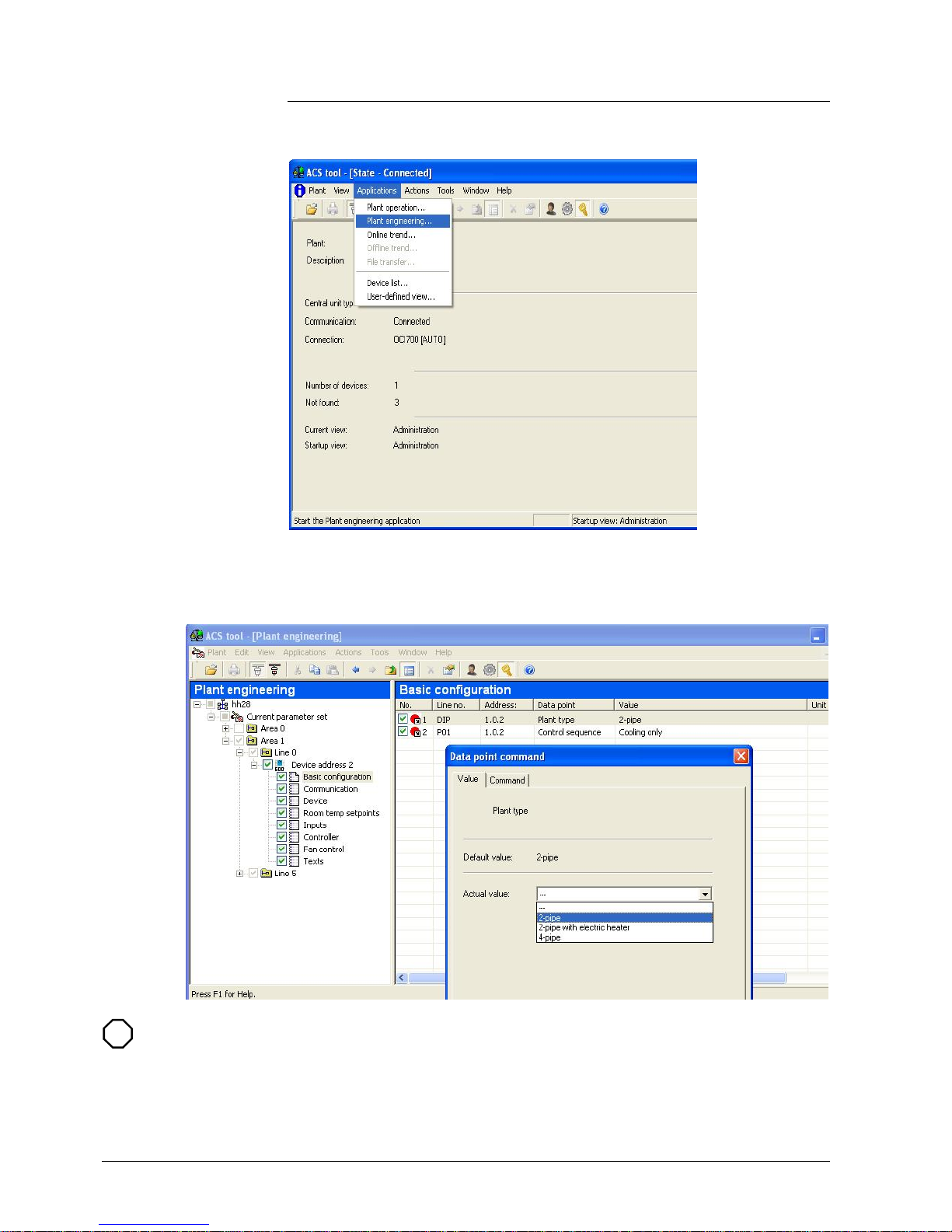
58 / 68
Siemens RDU341 Basic Documentation CE1P3172en
Building Technologies 2015-06-08
5.2.1 Parameter settings in ACS
In the ACS program, sel ect Plant, then Open to open the plant.
To start the parameter settings, select Applications, t hen Plant engineering…::
The application and control parameters can be adjusted and downloaded.
Column Line no. contains the parameter number as shown in the parameter table.
Refer to section 3.12.
Some parameters have a different range in ACS than in the room thermostats.
The thermostat does not accept changes that are outside its range. This can be
observed online by the fact that a changed value jumps back to the original value.
To be sure, use the ranges described in the parameter tables in section 3.12.
STOP
Note!
Page 59
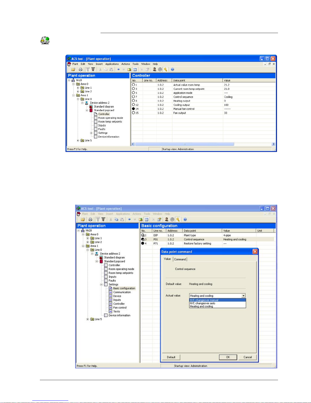
59 / 68
Siemens RDU341 Basic Documentation CE1P3172en
Building Technologies 2015-06-08
5.2.2 Operation and monitoring with ACS
In the ACS program, sel ect Plant, then Open to open the plant.
To start monitoring and operation, select Applications,then Plant operation.
ACS supports parameter settings even duri ng norm al operation.
To change a control parameter, select Popcard, then Settings.
· Make sure you have logged on with sufficient access right
· Only control parameter can be changed, no application!
ACS Operating
Parameter settings i n
ACS
Notes:
Page 60

60 / 68
Siemens RDU341 Basic Documentation CE1P3172en
Building Technologies 2015-06-08
ACS offers plant diagrams for easy monitoring and operation of the thermostat.
To start this application, select Applications, then Pant diagram
ACS provides standard plant diagrams for RDU KNX thermostats, which depend
on the configuration as follows:
Plant type
Application
Single duct
Single duct wit h electri c heater
Plant dia gram in ACS
Page 61

61 / 68
Siemens RDU341 Basic Documentation CE1P3172en
Building Technologies 2015-06-08
5.2.3 Operation and monitoring with OZW772
OZW772..
KNX TP1
Ethernet
USB Router
Internet /
Intranet
57 01 Z01a
Ethernet
Web browser
The OZW772 web server enables users to operate a Synco HVAC system from a
remote location – via PC or from a smart phone via the web. A start page shows
the most important data points. A combination of menu / path navigation enables
users to access all data points quickly and straightforwardly. The entire installation
can be visualized in the form of plant diagrams. Alarm and state messages can be
forwarded to differ ent message receivers, such as e-mail, SMS, etc.
For details, see Commissioning Instructions CE1C5701.
5.2.4 Operation and monitoring with RMZ972-B
The RMZ792-B is a communicating operator
unit designed for operating Synco™ 700 and
RDU KNX devices in a KNX network.
The operator unit is suited both for fixed
installation and mobile use (e.g. for use by the
service engineer) .
Third-party devices cannot be operated with it.
For details, see Basic Documentation CE1P3113.
The application cannot be displayed in the f orm of t ext, instead a number is used:
(Parameter Plant type on menu Basic setting):
0 = no application
1 = single duct
2 = single duct and electric heater
Note:
Page 62
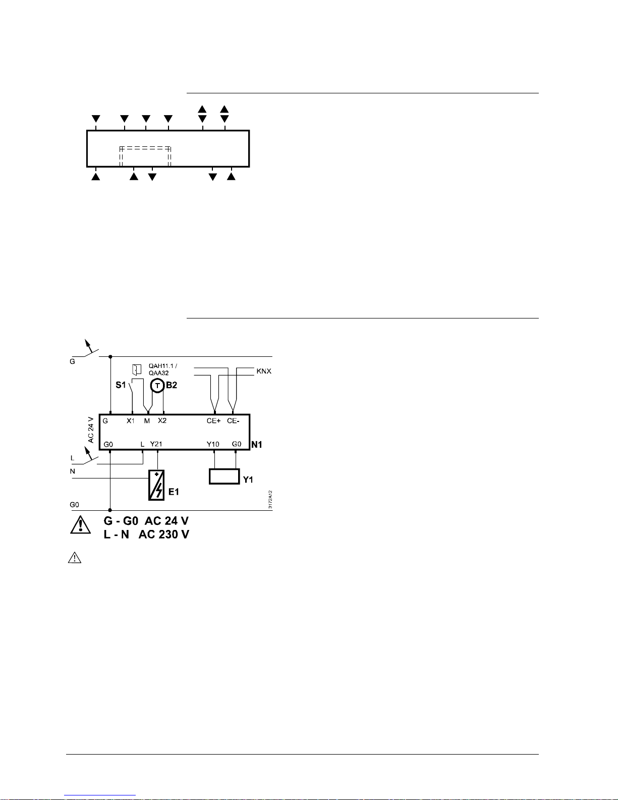
62 / 68
Siemens RDU341 Basic Documentation CE1P3172en
Building Technologies 2015-06-08
6. Connection
6.1 Connection terminals
G X1M
G0
Y10 G0
SELV
X2
3172A21
CE+ CE
-
L Y21
G, G0 Operating voltage SELV AC 24 V
L Supply for electric heater AC 230 V
Y10, G0 Output for damper, VAV compact controller
Y21 Output for electric heater
X1, X2 Multifunctional input for temperature sensor
(e.g. QAH11.1) or potential-free switch
Factory setting:
– X1 = Operating mode switchover contact
– X2 = External sensor
(function can be sel ected via parameter P38 / P40).
M Measuring neutral for sensor and swit ch
CE+ KNX data +
CE- KNX data -
6.2 Connection diagrams
10 A
10 A
N1 Room thermostat RDU341
Y1 Damper actuator, VAV c om pact control ler
E1 Electri c heater
S1, S2 Switch (keycard, window contact, etc. )
B1, B2 Temperature sensor (return air
temperature, external room temperature,
changeover sensor, etc.)
CE+ KNX data +
CE- KNX data -
For US installations, use Class 2 rated power supplies.
For other installations, use circuit breakers with rated current of no more than 10 A.
Page 63
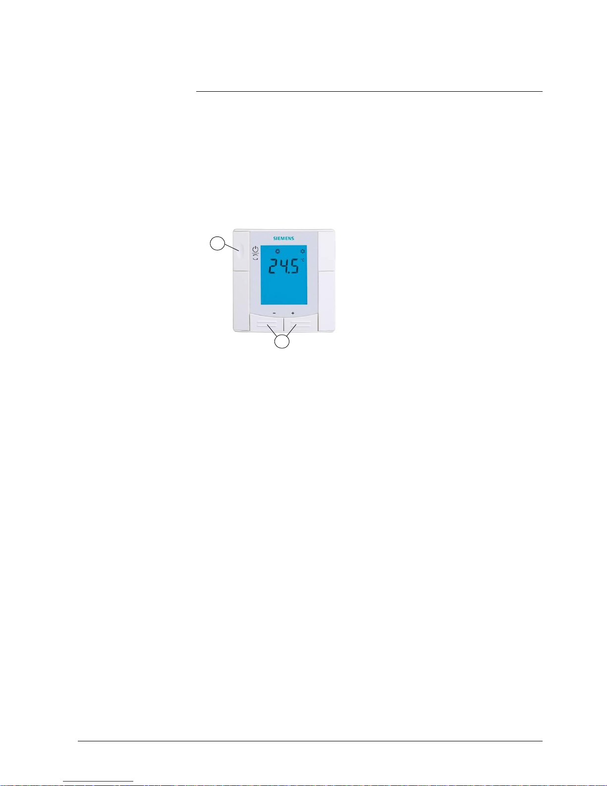
63 / 68
Siemens RDU341 Basic Documentation CE1P3172en
Building Technologies 2015-06-08
7. Mechanical design
7.1 General
The thermostats consist of 2 parts:
· Front panel with electronics, operating elements and built-in room temperature
sensor
· Mounting base wit h power electronics
The rear of the mounti ng base carries the screw terminals.
The base fits on a square conduit box with 60.3 mm fixed centers.
Slide the front panel in the mounting base and snap on.
1 Operating mode selector / Protection
2 Adjust setpoint and control parameters
1
2
Page 64
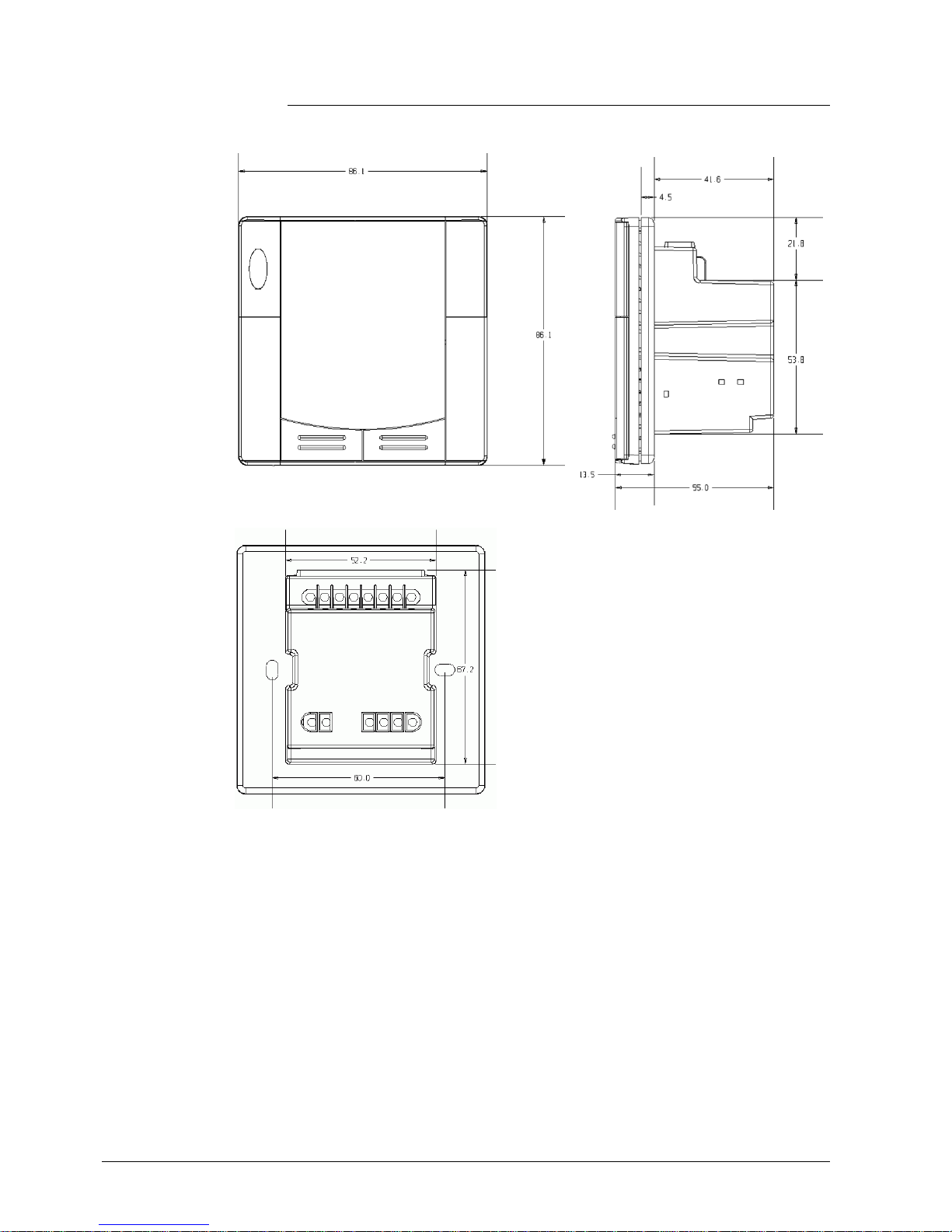
64 / 68
Siemens RDU341 Basic Documentation CE1P3172en
Building Technologies 2015-06-08
7.2 Dimensions
Dimensions in mm
Page 65

65 / 68
Siemens RDU341 Basic Documentation CE1P3172en
Building Technologies 2015-06-08
8. Technical data
Power supply
Operating voltage
DC 24 V: connect G to + and G0 to -
SELV AC 24 V / DC 24 V
or
AC 24 V / DC 24 V class 2 (US)
Rated voltage AC 24 V
Frequency 50/60 Hz
Power consumption Max. 2.5 VA / 0.9 W
External supply line protection (EU)
Circuit breaker max. 10 A
Characteristic B, C, D
according to EN 60898
or
Power source with current
limitation of max. 10 A
No internal fuse.
External preliminary protection with max. C 10 A circuit breaker in the
supply line requi red under all circumstances.
Outputs Control output Y21-N (N.O.)
Rating
AC 230 V
Max. 5(2) A
Control output Y10-G0
Resolution
Current
SELV DC 0…10 V
39 mV
Max. ±1 mA
Inputs Multifunctional input X1-M/X2-M
Temperature sensor input:
Type
Digital input:
Operating action
Contact sensing
Insulation against mains voltage (SELV)
QAH11.1 (NTC)
Selecta b le (N.O./N .C .)
SELV DC 0...5 V/max 5 mA
4 kV, reinforced insulation
Function input:
External temperature sensor, heating/cooling
changeover sensor, operating mode
switchover contact, dew point monitor
contact, enable el ectric heater contact, fault
contact, monitor input
Selectable
X1: P38
X2: P40
KNX bus Interface type KNX, TP1-64
(electrically isolated)
Bus current 20 mA
Bus topology: See KNX manual (see section 1.2)
Operational data Switching diff erential, adjustable
Heating mode (P30)
Cooling mode (P31)
2 K (0.5...6K)
1 K (0.5...6K)
Setpoint setti ng and range
Comfort (P08)
Economy (P11-P12)
Protection (P65-P66)
21°C (5...40 °C)
15°C/30°C (OFF, 5...40 °C)
8°C/OFF (OFF, 5...40 °C)
Multifunctional input X1/X2
Input X1 default value (P38)
Input X2 default value (P40)
Selectable 0...8
3 (Operating mode
switchover)
1 (External tem perature sensor)
Page 66

66 / 68
Siemens RDU341 Basic Documentation CE1P3172en
Building Technologies 2015-06-08
Built-in room tem perature sensor
Measuring range
Accuracy at 25 °C
Temperature calibrati on range
0…49 °C
< ± 0.5 K
± 3.0 K
Settings and display r esol ution
Setpoints
Current temperature value displayed
0.5 °C
0.5 °C
Environmental conditions Operation
Climatic conditions
Temperature
Humidity
As per IEC 60721-3-3
Class 3K5
0...+50 °C
<95 % r.h.
Transport
Climatic conditions
Temperature
Humidity
Mechanical condit ions
As per IEC 60721-3-2
Class 2K3
-25...+60 °C
<95 % r.h.
Class 2M2
Storage
Climatic conditions
Temperature
Humidity
As per IEC 60721-3-1
Class 1K3
-25...+60 °C
<95 % r.h.
Standards and directives EU Conformity (CE) CE1T3171xx
*)
RCM conformity
CE1T3171en_C1
*)
Electronic cont rol type
2.B (micro-disconnection on
operation)
Safety class II as per EN 60730
Pollution class Normal
Degree of protecti on of housing IP 30 as per EN 60529
General Connection terminal s Solid wires or prepared
stranded wires
1 x 0.4…2.5 mm
2
or 2 x 0.4…1.5 mm
2
Housing front color RAL 9003 white
Weight without / with packaging 0.163 kg / 0.233 kg
*)
The documents can be downloaded from http://siemens.com/bt/download
.
Page 67

67 / 68
Siemens RDU341 Basic Documentation CE1P3172en
Building Technologies 2015-06-08
Index
A
Air demand ......................................................... 40
Air heating / coo ling cha ng eover ......................... 23
Applica tion s overview ......................................... 22
Auto Ti mer mode ................................................ 15
Automat ic heat ing / cooling chan geo ver .............. 23
B
Button lock .......................................................... 24
C
Chang eover switch ............................................. 23
Control output VA V .............................................. 40
Control outpu ts co n figura tion ............................... 33
Control outputs overview ..................................... 33
Control para meters ............................................. 47
Control sequence s .............................................. 25
Cooling de mand .................................................. 40
D
DC 0..10 V control signal .................................. 3 3
Dew point mon itoring .................................... 2 4 , 34
Disposa l.............................................................. 56
E
Effect of Protect ion via time schedu le .................. 1 5
Electric heater ..................................................... 30
Enable / disa b le elec tr ic hea te r ........................... 34
Enable/d isa ble electr ic heate r ............................. 30
Expert level para mete rs ...................................... 4 7
Extens ion of Comfort mode ................................. 16
Externa l / return air temperatu re .......................... 34
Externa l / return a ir tempe ra ture s en s o r .............. 24
F
Fault ................................................................... 35
Fault on KNX ...................................................... 42
Fault, handling .................................................... 36
H
Heating / cooling changeo ver .............................. 3 4
Heating deman d ................................................. 40
I
Integra l action time .............................................. 12
M
Monitor ing with ACS ............................................ 59
Mounting and installat ion .................................... 52
Multifunc tiona l input s .......................................... 34
O
ON/OFF control output signals............................ 33
Operating mode
Priority inte rvention ......................................... 14
Operating mo de button ....................................... 15
Operating m od e switcho ver ................................ 34
Operation w ith AC S ............................................ 59
P
Parame ter setting ............................................... 47
Parame ter setting s in ACS .................................. 59
Plant diagra ms in ACS ........................................ 60
Precomfo rt ......................................................... 15
Proportion al ban d ............................................... 12
Protect ion mode / Sta ndb y .................................. 13
R
Remote hea ting / cool ing cha n ge o ver ................ 23
Rese t parameters ............................................... 47
S
Sens or input ....................................................... 34
Setpoint Co mfort mode ....................................... 32
Setpoint Econo my mode ..................................... 32
Setpoint li mitat ion ............................................... 19
Setpoint P rotection mode ................................... 32
Setpoints and sequences.................................... 32
St and by / Protection mod e .................................. 13
Supply a ir temperatu re ....................................... 23
Switching dif ferentia l ........................................... 12
T
Temperature out of range ................................... 36
T e mporary se tpoint ............................................. 19
Time sch ed ule cha ng e mode .............................. 15
V
V A V change over ................................................. 23
V AV change o ver via bus ..................................... 25
W
Window conta ct ................................................. 15
Window state ........................................... 1 3, 14, 34
Page 68

68 / 68
Siemens RDU341 Basic Documentation CE1P3172en
Building Technologies 2015-06-0 8
Siemens Switzerland Ltd
Building Technologies Division
International Headquarters
Gubelstrasse 22
CH-6301 Zug
Tel. +41 41-724 24 24
www.buildingtechnologies.s iemens.com
© 2010 -2015
Siemens Switzerland Ltd
Subject to change
 Loading...