

Page 1
s
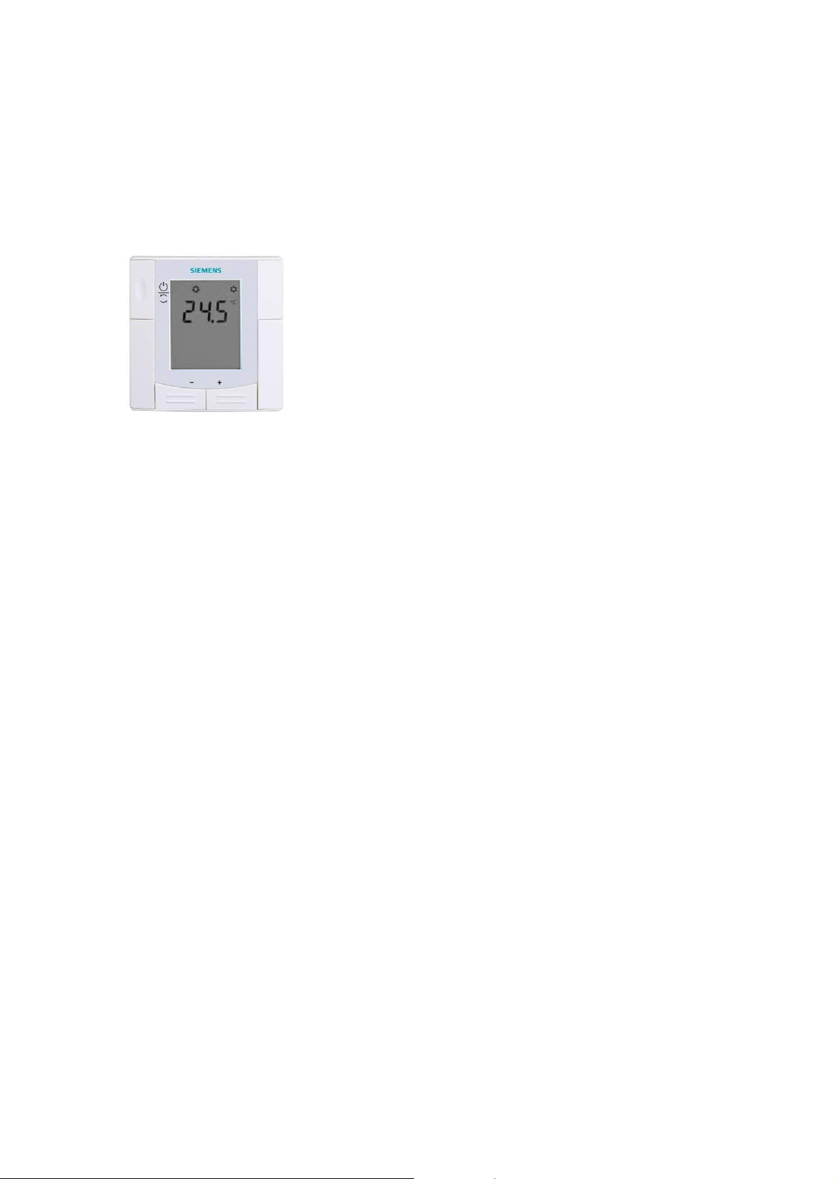
Flush-mounted room temperature controllers for
VAV / CAV applications, with LCD
RDU340
Basic Documentation
Edition: 3.0
CE1P3078en
2014-11-03
Building Technologies
Page 2

2 / 32
Siemens Basic Documentation CE1P3078.en
Building Technologies 2014-11-03
Page 3

Table of contents
1 About this document ........................................................................... 4
1.1 Revision history ..................................................................................... 4
1.2 Reference documents ............................................................................ 4
1.3 Before you start ..................................................................................... 4
1.3.1 Copyright ............................................................................................... 4
1.3.2 Quality assuran ce .................................................................................. 4
2 Summary .............................................................................................. 5
2.1 Brief descript ion ..................................................................................... 5
2.2 Features ................................................................................................ 5
2.3 Typ e summa ry ....................................................................................... 5
2.4 Equipment combinations ........................................................................ 6
2.5 Accessories ........................................................................................... 7
2.6 Ordering ................................................................................................ 7
3 Use ....................................................................................................... 7
4 Functions ............................................................................................. 8
4.1 T emperature control ............................................................................... 8
4.2 Operating modes ................................................................................... 9
4.3 Setpoint s ............................................................................................. 1 0
4.4 Applications ......................................................................................... 1 1
4.5 Addition al featu res ............................................................................... 12
4.6 Contro l sequen ces ............................................................................... 14
4.6.1 Single duct ........................................................................................... 14
4.6.2 Single duct with electr ical heater .......................................................... 16
4.7 Contro l output ...................................................................................... 17
4.8 Multifunc tional input ............................................................................. 1 8
4.9 Error handl ing ...................................................................................... 19
4.10 DIP switches ........................................................................................ 19
4.11 Contro l para meters .............................................................................. 2 0
5 Handling ............................................................................................. 23
5.1 Mounting and inst allation ..................................................................... 23
5.2 Operating Instructions .......................................................................... 24
5.3 Dispo sal .............................................................................................. 24
6 Engineering ........................................................................................ 25
6.1 Conne ction terminals ........................................................................... 25
6.2 Conne ction diagra ms ........................................................................... 25
7 Mechanic al desi gn ............................................................................. 26
7.1 Dimensions .......................................................................................... 27
8 Tec hnical data .................................................................................... 28
3 / 32
Siemens RDU340… Basic Documentation CE1P3076.en
Building Technologies Table of contents 2014-11-03
Page 4
1 About this document
1.1 Revision history
Edition Date Changes Section Pages
3.0 2014-10-21 Update for RoHS 2.0 and
overcurrent protection and other
minor changes
2.0 2014-09-04 Update P51
Mounting and wiring information
Date format changed in line with
ISO 8601 specif ications (yyyy-mmdd format).
1.0 2008-07-11 First edition
5.1
5.3
6.2
8
1.2 Reference documents
Ref. Document title Type of document Document No.
N3078 Flush-mounted room temperature
controllers with LCD
B3076 Operating Instructions CE1B3076en
M3078 Mounting Instructions CE1M3078xx
Datasheet CE1N3078en
23
24
25
28
1.3 Before you start
1.3.1 Copyright
This document may be duplicated and distributed only with the express permission
of Siemens, and may be passed only to authorized persons or companies with the
required technic al knowledge.
1.3.2 Quality assurance
These documents have been prepared with great care.
· The contents of all documents are checked at regul ar intervals.
· Any corrections necessary are included in subseque nt versions.
· Documents are automatically amended as a consequence of modifications and
corrections to the products described.
Please ensure that you are aware of the latest revision date of the documentation.
If you find any lack of clarity while using this document, or if you have any criticisms
or suggestions, please contact the product manager in your nearest branch office,
or write directly to the support team at Headquarters in Zug (see below).
Support address:
Siemens Switzerl and Ltd.
Building Technologies Group
International Headquarters
Field Support 5500
Gubelstrasse 22
6301 Zug, Switzerl and
Tel. +41 41 724 5500
Fax. +41 41 724 5501
E-mail: fieldsupport-zug.ch.sbt@siemens.com
4 / 32
Siemens RDU340… Basic Documentation CE1P3078en
Building Technologies About this docu ment 2014-11-03
Page 5

2 Summary
2.1 Brief description
The devices support VAV heati ng and cooli ng systems:
· Modulating PI / P control
· Control depending on the room or the return air temperature
· Output for a DC 0…10 V actuator and AC 230V electrical heater (ON-OFF)
· Automatic or manual heating/cooling changeover
· Operating modes: Comfort, Energy Saving and Protection
· Two multifunction al inputs for keycard contact, external sensor, etc.
· Adjustable commissioning and control parameters
· Minimum and maximum setpoint limitation
· Adjustable minimum and maximum limitation of output signal DC 0..10V
· Output signal inversion as an option
· Mounting on recessed rectangular conduit box, 60.3 mm fixing centers
· AC 24 V operating voltage
2.2 Features
· Maintain room temperature via built-in t emperature sensor external room
temperature / return air temperature sensor
· Automatic or manual changeover between heating and cooli ng mode
· Sel ect appli cations v ia DI P switches
· Select operating mode via the operating m ode button on the controller
· Display current room temperature or setpoint in °C and/or °F
· Mi nimum and maximum setpoint limit ation
· Key lock (automatic and m anual)
· Two m ultifuncti onal inputs, f reely selectable for:
– Operating mode swi tchov er contact (key car d)
– Aut omatic heating/cooling changeov er sensor
– External room temperature or ret urn air temperature
– Dewpoint sensor
– Electri c heater enabl e
– Alarm input
· Minimum and maximum limitation of air fl ow signal DC 0..10V
· Fl oor heating temperature limit
· Reload factory settings for commi ssioning and control parameters
2.3 Type summary
Control output
Product
number
RDU340 AC 24 V
Siemens RDU340… Basic Documentation CE1P3078en
Building Technologies Summary 2014-11-03
Operating Voltage
3 pt on/off DC 0..10 V
--
ü ü white
LCD
Backl ig ht
Infrared
receiv er
Housing
5 / 32
Colour r
Page 6
DC 0..10 V actuators
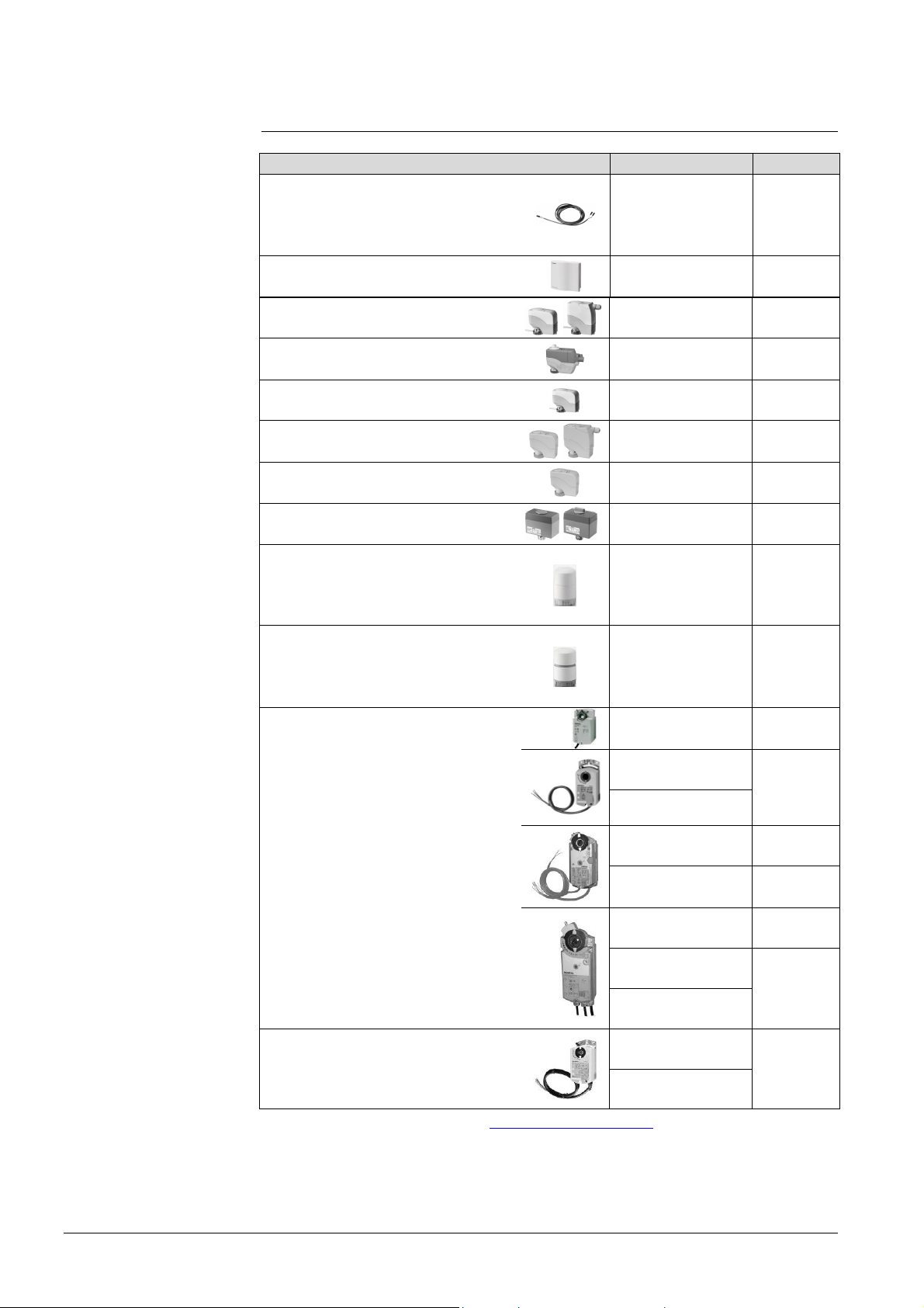
2.4 Equipment combinations
Type of unit Product number Data sheet
Cable temperat ure sensor or
changeover sensor,
cable length 2.5 m
NTC (3 kW at 25 °C)
Room temperature sensor
NTC (3 kW at 25 °C)
Electrical actuator, DC 0..10V
(for radiator valve)
Electrical actuator, DC 0...10 V
(for 2- and 3-port valves / V…P45)
Electrical actuator, DC 0..10V
(for small valve 2,5 mm)
Electrical actuator, DC 0..10V
(for small valves 5.5 mm)
Electrical actuator, DC 0...10 V
(for CombiValves VPI45)
Electromotori c actuator, DC 0..10V
(for valves 5.5 mm)
Electrothermal actuator,
AC 24 V, NC, DC 0…10 V, 2 m
(for radiator valves and small valve
2.5 mm)
Electrothermal actuator,
AC 24 V, NO, DC 0…10 V, 2 m
(for radiator valves and small valve
2.5 mm)
QAH11.1
QAA32
SSA61...
SSC61…
SSP61…
SSB61...
SSD61...
SQS65…
STA 63
STP63
1840
1747
4893
4895
4864
4891
4861
4573
4884
4884
GQD161…
GDB161…
GLB161…
GMA161…
DC 0…10 V damper actuator
GEB161…
GCA161…
GBB161…
GDB181.1E/3
VAV compact controller
GLB181.1E/3
*) The docum ent s can be downloaded fr om http://siemens.com/bt/download.
4605
4634
4614
4621
4613
4626
GIB161…
3544
6 / 32
Siemens RDU340… Basic Documentation CE1P3078en
Building Technologies Summary 2014-11-03
Page 7

2.5 Accessories
*)
Designation Product no. Data Sheet
Changeover mounting kit (50 pcs/package)
Plastic mounting spacer for flush mounted
thermostats for increasi ng the headroom in the
conduit box by 10 mm
Conduit box for flush mounted thermostat
*) The docum ent s can be downloaded fr om http://siemens.com/bt/download.
ARG86.3
ARG70.3
ARG71 /
S55770-T137
N3009
N3009
N3009
2.6 Ordering
When ordering, i ndicate both product number and name:
E.g. RDU340 room temperature controller
Order valve actuators separately.
3 Use
Control of the room temperature in individual rooms of ventilation or air
conditioni ng plants that are:
· Heat ed or cooled by single duct.
· Heated and cooled by single duct with aux iliary electrical heater.
The RDU340 is suitabl e for use with VAV systems in connection with the VAV
compact controll ers types G…B181.1E/3.
The RDU340 control s
· One DC 0…10 V actuator
· One DC 0…10 V actuator and AC 230V 1-stage electrical heater
Use in systems with:
· Heating or cooling m ode
· Automatic heating/cooling changeov er
· Manual heating/cooli ng changeov er
· Heating and cooling (single duct with electrical heat er)
7 / 32
Siemens RDU340… Basic Documentation CE1P3078en
Building Technologies Use 2014-11-03
Page 8
4 Functions
4.1 Temperature control
General note
Display
/
The setting of t he control parameters (P01 etc., mentioned throughout the
document) is descri bed in section 4.11.
The controller acquires the room temperat ure via built-in sensor, external room
temperature sensor (QAA32), or external return air temperature sensor (QAH11.1),
and maintains the setpoint by issuing actuator control commands to heating and/ or
cooling equipment. The following control outputs are available:
· Modulating PI / P control wi th DC 0..10 V control output for actuators and ONOFF for electrical heater.
The switching differential or proportional band is 2 K for heating mode and 1 K for
cooling mode (adjustable via parameters P30 and P31).
The integral action time for continuous PI control is 5 minutes (adjustable via
parameter P35).
The display shows the acquired room temperat ure or the setpoint for the current
operating mode, selectable via parameter P06. The factory setting displays the
current room temperature.
Use parameter P04 to display the room temperature or setpoint in °F rather than
°C as needed.
If the control ler is used in a system with manual heating/cooling changeover
(P01=2), the heating
unit status. Thus, the symbols are displayed even when the cont roll er operates in
the neutral zone. For all other cases, the heating
displayed when the heating or cooling out put is energized.
and cooling symbols on the display show the terminal
and cooling symbols are
Concurrent display of
°C and °F
Concurrent di splay of the current tem perature or setpoint in °C and in °F
(parameter P07) is possible on the controller without weekly time program.
8 / 32
Siemens RDU340… Basic Documentation CE1P3078en
Building Technologies Functions 2014-11-03
Page 9

4.2 Operating modes
Select the controller's operating mode via operating mode button on the
controller or operating mode input (e.g. keycard occupancy sensor, when X1 or X2
set to 3 (P38, P40)). A corresponding setpoint is used to maintain the room
temperature at the desired level depending on the active operating mode. The
following operating modes are available:
Comfort mode
Energy Saving
Note
Standby
/Protection mode
In Comfort mode, the controller maintains the setpoint which can be adjusted via
the +/- buttons.
Energy Saving mode helps save energy. Select it by pressing the operating mode
button
if parameter P02 is set accordingly, or if the external operating mode
switchover contact is active (e.g. window contact).
If the external operating mode switchover contact is active, user operations are
ineffective and “OFF” is displayed. Control wil l then be according to energy saving
setpoints (P11 and P12).
In Standby mode, the system is
– prot ected against frost (f actory setting 8 °C, can be disabled or changed via P65).
– prot ected against ov erheating (factory setting OFF, can be enabled or changed
via P66)
9 / 32
Siemens RDU340… Basic Documentation CE1P3078en
Building Technologies Functions 2014-11-03
Page 10
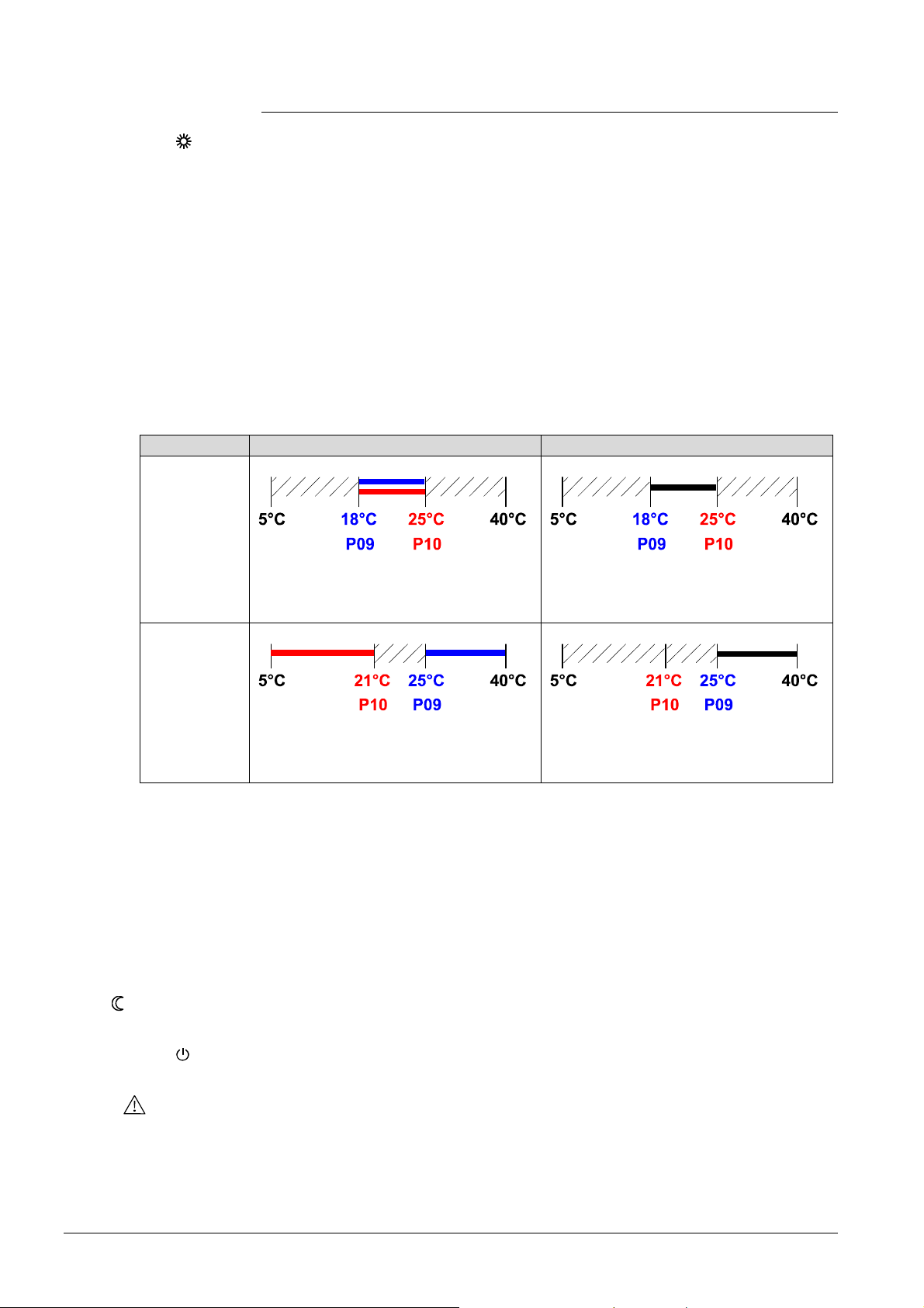
4.3 Setpoints
Comfort mode
Setpoint limitation
P09 < P10
P09 ≥ P10
Examples Sin gle duct heating or cooling Single duct co oling with el he ater
P09 < P10
The setpoint in Comfort mode can be adjusted via the +/- buttons.
For energy saving purposes, t he setpoint adjusting range can be limited to
minimum (P09) and maximum (P10).
· If the mi nimum limit P09 is set lower than the maximum limit P10, both heating
and cooling are adjustable between these two limit s.
· For heating or cooling applications (e.g. single duct)
– The setting range in cooling mode is from P09…40° instead of 5…40°
– The setting range in heating mode is from 5…P10° instead of 5…40°
· For cooling and heating wit h el. heater applications (e.g. singl e duct)
– The setting range is from P09…40° instead of 5…40°
– The setpoint for the el. heater is maximal limited by P10
Cooling setpoi nt adjustable 18…25°C
Heating setpoint adjustable 18…25°C
Setpoint adjustable 18…25°C
Heating setpoi nt := Cooling setpoint –
dead zone
P09 ≥ P10
Temporary setpoi nt
Energy Saving
mode
Standby mode
Cooling settable 25…40°C
Heating settable 5…21°C
Setpoint adjustable 25…40°C
Heating setpoi nt := Cooling setpoint –
dead zone, but max (limited by) P10
If the “Temporary setpoint function” is enabled via parameter P69, the setpoint
adjusted via the +/- buttons is set back to the Comfort basic setpoint when the
operating mode changes.
The factory setting for the Comfort basic setpoint is 21 °C and can be changed via
parameter P08.
Use control parameters P11 and P12 to adjust the Economy mode setpoints.
The heating setpoint is factory-set to 15 °C and to 30 °C for cooling.
Use control parameters P65 and P66 to adjust the Standby mode setpoints.
The heating setpoint is factory-set to 8 °C (frost protection) and to OFF for cooling.
Caution
If a setpoint is set to OFF (P65, P66), the controller does not maintain the setpoint
in the corresponding mode (heating or cooli ng).
This means no protective heating or cooling function and thus risk of frost in the
heating mode or risk of overheat in cooling mode!
10 / 32
Siemens RDU340… Basic Documentation CE1P3078en
Building Technologies Functions 2014-11-03
Page 11

4.4 Applications
The controll er supports following applicati ons, whi ch can be configured by DIP
switches on the inner side of the controller front panel.
Application and output signal, DIP switches, diagram
Single duct,
heating or cooling
Modulating, DC 0…10 V output signal normal
V
M
Y10
Single duct with electrical heater,
cooling and heati ng, with auxiliary heater
Modulating, DC 0…10 V output signal
normal
Note: on-off el ectri cal heater
B2
1ON2
Single duct,
heating or cooling
1ON2
Modulating, DC 0…10 V output signal
inverted
B1
Single duct with electrical heater,
cooling and heati ng, with auxiliary heater
DC 0…10 V output signal inverted
Note: on-off el ectri cal heater
1ON2
1ON2
MV
Y21
Y10
B1
V1 Heating or heating / cooling valve actuator B1 Return air temperature sensor or external room
temperature sensor (optional)
E1 Electric heater B2 Changeov er sensor (opti onal)
11 / 32
Siemens RDU340… Basic Documentation CE1P3078en
Building Technologies Functions 2014-11-03
Page 12

4.5 Additional features
Automatic H/C
changeover
Remote heating/
cooling changeover
The air or water temperature acquired by the changeover sensor (QAH11.1) is
used to change over from heating to cooling mode and vice-versa. When the water
temperature is above 28 °C (parameter P37), the controller changes over to
heating mode, and to cooling mode when below 16 °C (parameter P36). If the
water temperature is between the 2 changeover points immediately after power up,
the controller starts in heating mode. The water tem perature is acquired at 30second interv als and the operating state is updated accordingly.
M Operating mode Cooling m od e
Tw Air or water t emperatur e
Heating m od e
The QAH11.1 cable temperature sensor for automatic heating/cooling changeover
can be replaced by an external switch for manual, remote changeover:
Contact open à heating mode
Contact closed à cooling mode
External/return
temperature sensor
Dewpoint monitoring
Key lock
The sensor or switch can be connected to the input terminal of X2 (factory setting)
or X1 depending on the commi ssioning of inputs X1 and X2. See also secti on
“Multifunctional input”.
The controller acquires the room temperat ure via built-in sensor, external room
temperature sensor (QAA32), or external return air temperature sensor (QAH11.1)
connected to multifunctional input X1 or X2.
Inputs X1 or X2 need to be commissioned accordingly. See section 4.8 “Multifunctional input”.
Dewpoint monit ori ng is essential to prevent condensation on the chilled ceiling and
help avoid associated damage to the building. This is an optional function and is
provided in case the controller is used for a chilled ceiling application.
A dewpoint sensor with a voltage-free contact is connected to multifunctional input
X1 or X2. If there is condensation, the cooling valve is fully closed until no more
condensation is detected and the cooling output is disabled temporarily. The
condensation symbol
is displayed during t em porary override.
Input X1 or X2 must be commissioned acc ordingly.
See section “4.8 Multifunctional input”.
If the key lock function is enabled by parameter P14, then pressing 7 seconds on
the operating mode button
, the keypad will be locked or unl ocked respectively.
If “Auto lock” is configured, then the controller will automatically lock the keypad
after 30 seconds of the last adjustment.
Min / Max air flow
12 / 32
Siemens RDU340… Basic Documentation CE1P3078en
Building Technologies Functions 2014-11-03
Page 13

The output signal of the air flow (DC 0..10V) can be limited to a minimum value by
Output signal inversion
using parameter P63 and to a maximum value using parameter P64. These air flow
limitation values can be set between 0% and 100%.
This is used to ensure a minimum or maximum supply air volume.
T Room temperature
Y10 Control output
W Room temperature setpoint
XpH Proportional band Heat ing
XpC Proportional band Cooling
Vmin Minimum limitation air flow
Vmax Maximum limitation air flow
The output signals DC 0…10V can be inverted by means of DIP switch #2.
– If DIP switch #2 is set to “OFF”, 0V corresponds to 0% trav el and 10V to 100%
(factory settti ng).
– In position ON, 0V corresponds to 100% t rav el and 10V to 0% t ravel.
This function is useful in conjunction with normally open valves.
Floor temperature
limit a tion function
The floor tem perature should be limited for 2 reasons: Comfort and protection of
the floor.
The floor temperature sensor, connected to multifunctional input X1, acquires the
floor temperature. If the floor tem perature exceeds the parameterized limit
(parameter P51), the heating valve is fully closed until the floor temperature drops
to a level 2 K below the parameterized limit.
This function is factory-set to OFF (disabled).
Input X1 or X2 must be commissioned acc ordingly (P38 = 1).
See section 4.8“Multifunctional input”.
Recommended values
for P51:
Living rooms:
Up to 26 °C for long-time presence, up to 28 °C for short-time presence.
Bath rooms:
Up to 28 °C for long-time presence, up to 30 °C for short-time presence.
The table below shows the relation between parameter, temperature source and
temperature display:
Parameter P51
External temp.
sensor availabl e
Source f or display of
room temperature
Output control
according to
OFF No Built-in sensor Built-in sensor Not active
OFF Yes External temp. sensor External temp. sensor Not active
10...50 ˚C No Built-in sensor Built-in sensor Not active
10…50 ˚C Yes Built-in sensor
Built-in sensor + limit
by external sensor
Floor temp.
limit. function
Active
Siemens RDU340… Basic Documentation CE1P3078en
Building Technologies Functions 2014-11-03
13 / 32
Page 14

4.6 Control sequences
4.6.1 Single duct
If the selected application is "singl e duct", then the controll er can be used in
systems featuri ng:
– Heating or cooling m ode (P01=0 or P01=1).
– Manual heating/cooling changeover (P01=2).
– Aut omatic heating/cooling changeov er (P01=3).
The relevant modes can be adjusted via commissioning parameter “Control
sequence” P01, dependi ng on the selected application.
Sequence
Parameter P01 = 0 P01 = 1 P01 = 2 P01 = 3
Mode
Available for:
Single duct
Heating mode Cooling mode
ü ü ü ü
Manually select
heating or cooling
mode
Automatic
heating/cooling
changeover via
external water
temperature
sensor or remote
switch
Single duct,
heating or cooling
Control sequence
modulating output
In application "Single duct with el. heater", the controller operates in heating AND
cooling mode.
In single duct applications, the controller controls an actuator (valve, damper, VAV
system, etc)
– in heating/cooling mode with changeover (automatic or manual),
– heating only mode,
– or cooling only mode.
Cooling only is factory set (P01=1).
The output can be limited to a minimum and maximum value if required.
See section 4.5 "additional features".
The diagram below shows the control sequence for c ontinuous PI control.
Heating only mode Cooling only mode
Changeover
14 / 32
Siemens RDU340… Basic Documentation CE1P3078en
Building Technologies Functions 2014-11-03
Page 15

T[°C] Room temperature
w Room temperature setpoint
Y10 Control command “Valve”
XpH Proportional band “Heating”
XpC Proportional band “Cooling”
Vmin Min. limitation for output
Vmax Max. limitation for output
Note
The diagrams show the PI controller’s proportional part only
15 / 32
Siemens RDU340… Basic Documentation CE1P3078en
Building Technologies Functions 2014-11-03
Page 16

4.6.2 Single duct with electrical heater
If the selected application is "single duct & el. heater", then the controller works in
heating and cooling mode.
The output can be limited to a minimum and maximum value if required.
See section 4.5 "additional features".
Single duct
with el. heater
Digital input “Enable
electrical heater”
Control sequence
In single duct appli cations with electrical heater, the controll er controls an actuator
(valve, damper, VAV system, etc.) plus an auxili ary electrical heater.
Note: The setpoint for the electrical heater is limited by parameter “Maximum
heating setpoint” (P10).
Remote enabling/disabling of the electrical heater is possible via digital input X1/X2
for tariff regulations, energy saving etc.
Input X1 or X2 must be commissioned accordingly. See section “4.9 Multifunctional
input”.
The diagram below shows the control sequence for continuous PI control.
Cooling and heating with electric heater
TR[°C] R oom temper ature Vmin Min. limitation for output
W Room temperature setpoint Vmax Max. limitation for output
Y10 Control command “actuator” XpC Proportional band “Cooling”
Y21 Control command “electrical heater” Xdz Dead zone
SDH Switching differential
Note: The diagrams show the PI controller's proportional part only.
16 / 32
Siemens RDU340… Basic Documentation CE1P3078en
Building Technologies Functions 2014-11-03
Page 17

4.7 Control output
Overview of control
output
DC 0...10 V control
signal
Electrical heater
control signal
(2-position)
Different control output signals are available depending on the controller type.
Control output
T ype reference
on/off 3-position DC 0…10 V
RDU340 Y21 (1) -- Y10 (1)
( ) Number of outputs
The demand calculated by the PI control from the current room temperature and
setpoint is provided to the valve actuator as a continuous DC 0...10 V signal via
output Y10.
The electrical heat er receives an ON command via the auxiliary heating control
output Y21:
1. When the acquired room tem perature is below “setpoint for el ectric heater”.
2. When the electri cal heater has been switched off for more than 1 minute.
The OFF command for the electrical heater is output:
1. When the acquired room tem perature is abov e t he setpoint (el ectric heater).
2. When the electrical heater has been switched on f or more t han 1 minut e.
Caution
A safety thermostat (to prevent overheating) must be provided externally.
17 / 32
Siemens RDU340… Basic Documentation CE1P3078en
Building Technologies Functions 2014-11-03
Page 18

4.8 Multifunctional input
The controller offers two multifunctional inputs X1 and X2. A sensor of type NTC
like QAH11.1 (AI) or a switch (DI) can be connected to the input terminals. The
functionality of both inputs can be configured via parameters P38 for input X1 and
P40 for input X2.
# Function of input X1/X2 Description Type
0 Not used No function. 1 External/Return air temp. Sensor input ex ternal room
temperature sensor or return air
temperature sensor to measure the
current room temperature.
2 Heat/cool changeover Sensor input for automatic
heating/cooling changeover
function. A switch can also be
connected rather than a sensor.
3 Operating mode switchover Digital input to switch over the
operating mode to Energy Saving.
If the operating mode switchover
contact is active, user operat ions
are ineffective and “OFF” is
displayed.
4 Dewpoint monitor Digital input for a dewpoint sensor
to detect condensation. Cooling is
stopped if condensati on occurs.
5 Enable electrical heater Digital input to enable/disable the
electrical heater via remote control.
6 Alarm Digital input to signal an alarm.
If the input is active, “ALx” (x:=1 or 2)
is displayed.
Note: Alarm displays do not influence controller operations. They
merely represent a visual signal.
Example: No air flow or el. heater
overheated.
AI
AI/(DI)
DI
DI
DI
DI
Operational action can be changed between normally open (N. O.) and normally
closed (N.C.) via parameter P39 or P41 if it is a digital input (DI).
Each function can only be assigned to input X1 or X2; only “Alarm” can be
assigned to both i nputs.
X1 is factory-set to “Operating mode switchover” (3) and X2 to “Heating/cooling
changeover” (2).
For more information see section 4.4 “Applications”.
18 / 32
Siemens RDU340… Basic Documentation CE1P3078en
Building Technologies Functions 2014-11-03
Page 19

4.9 Error handling
Temperature out of
range
ON
1 2
When the room temperature is outside the measuring range, i.e. above 49 °C or
below 0 °C, the limiting temperatures flash, e.g. “0 °C” or “49 °C”.
If the temperature is below 0 °C and the controller is in heating mode and the
current setpoint is not set to “OFF”, then the control output Y10 or Y21 respectively
will issue actuator c ontrol commands to heating equipment.
For all other c ases, the control output i s de-energized. The controller resumes
Comfort mode after the temperature returns to within the measuring range.
4.10 DIP switches
Use the DIP switches on the inner side of the front panel to commission the basic
controller applications prior to snapping it to the base.
DIP switch number
Application
Single duct (factory setting) OFF n.a.
Single duct & electrical heater ON n.a.
DC 0…10 V output signal normal (factory setting) n.a. OFF
DC 0…10 V output signal inverted (see section 4.5) n.a. ON
1 2
Note: Duri ng startup, the controller reloads the control parameter factory settings
after each DIP switch settings change.
19 / 32
Siemens RDU340… Basic Documentation CE1P3078en
Building Technologies Functions 2014-11-03
Page 20

4.11 Control parameters
A number of control parameters can be readjusted to optimize control perf ormance.
These parameters can also be set during operation without openi ng the unit. In the
event of a power failure, all control parameter setti ngs are retained.
The control parameters are divided in two levels:
· “Service” level, and
· “Expert” level.
The “Service” level contains a small set of parameters to set up the controller for
the HVAC system and to adjust the user interface. These parameters can usually
be adjusted any time.
Change parameters in the “Expert” level only carefully, as they impact control
performance and functionality of the controller.
Parameter setting
Enter only “Serv ice”
level
Enter “Service” and
“Expert” level.
Adjust parameters
Reset parameters
Change the parameters as follows:
1. Set the controll er to Standby
*)
2. Press button s + and - sim ultaneously for 3 seconds. Release and press
button + again f or 3 seconds wit hin 2 seconds. The display shows “P01”.
Continue at Step 3.
1. Set the controll er to Standby *)
2. Press button s + and - sim ultaneously for 3 seconds. Release and press
button - again for 6 seconds within 2 seconds. The display shows “P01”
and service.
3. Sel ect the required parameter by repeatedly pressing buttons + and -.
4. When you press buttons + and - sim ultaneously, t he current v alue of the
selected paramet er starts to fl ash, which can be changed by repeatedly
pressing buttons + or -.
5. When you again press buttons + and – simultaneously, the next paramet er
is displayed.
6. Repeat Steps 3 to 5 to displ ay and change additional param eters.
7. All changes are saved and the controller returns to Standby 10 second s
after the last display or setting.
The factory setting for the control parameters can be reloaded via parameter P71,
by changing the value to “ON”, and confirming by pressing buttons + and –
simultaneously. The display shows “8888” during reload.
Note
*) If one of the digital inputs is commissioned as window contact, and the contact is
closed, the controller will switch to ECO mode and parameter setting will not be
possible. Solution: open the window contact.
20 / 32
Siemens RDU340… Basic Documentation CE1P3078en
Building Technologies Functions 2014-11-03
Page 21

Control parameters
# Parameter
Service Level
P01 Control sequence
(for appl ication "s in gle duct" only)
P02 Mode selection via user operating mode button 1 (Stb, Comf) 1 = Stb,Comf
P04 Selection of °C or °F °C (0) °C
P05 Sensor calibration 0.0 K – 3 ... +3 K
P06 Standard temperature display 0 (Room temp) 0:= Room temperature
P07 Additional user info 0 (no disp lay) 0:= no display
P08 Comfort basic setpoint 21 °C 5 ... 40 °C
P09 Minimum setpoint limitation for Comfort (WminComf) 5 °C 5 ... 40 °C
P10 Maximum setpoint limitation for Comfort (WmaxComf) 35 °C 5 ... 40 °C
P11 Heating setpoint for Energy Saving (WheatEco) 15 °C OFF, 5 °C…W c oolEco
P12 Cooling setpoint for Energy Saving (WcoolEco) 30 °C OFF, WheatEco…40 °C
P14 Key lock
(Press th e operati ng mode button
enabl e or disable the key lock)
for 7 seconds to
Factory
setting
1 (Cooling only) 0:= Heating only
0 (Unlocked) 0:= Unlocked
Setting range
1:= Cooling only
2:= Manual H/C
3:= Auto changeover
2 = Stb, Comf, Eco
(1) °F
1:= Setpoint
1:= Temp in °C and °F
1:= Auto lock
2:= Manual lock
RDU340
ü
ü
ü
ü
ü
ü
ü
ü
ü
ü
ü
ü
Note
· P01 is not available when the controll er is commissioned as si ngle duct with el.
heater (DIP switch #1 = ON)
· P02 is not av ailable when the controller is comm issioned for manual
heating/cooling changeover (P01=2)
· Parameter display depends on selected application and f unction
(x) Not availabl e
21 / 32
Siemens RDU340… Basic Documentation CE1P3078en
Building Technologies Functions 2014-11-03
Page 22

# Parameter
Factory
setting
Setting range
RDU340
Expert Level
P30 P-band/switching differential for heating mode 2K 0.5 … 6 K ü
P31 P-band/switchin g differential for cooling mode 1 K 0.5 … 6 K ü
P33 Dead zone in Comf ort m ode 2 K 0.5 … 5 K ü
P35 Integral ti m e 5 min 0…10 min ü
P36 Heating/cooling changeover switching point for cooling 16 °C 10…25 °C ü
P37 Heating/cooling changeover switching point for heat ing 28 °C 27…40 °C ü
P38 X1 functionality 3 (Op mode
switchover)
0:= NA
1:= Ext/Return air temp
ü
2:= Heat/cool changeover
3:= Operating mod e switch
4:= Dewpoint monitor
5:= Enab le electrical heater
6:= Alarm input
P39 Operating action for X1 if digital input 0 (N.O.) 0:= Normally open
ü
1:= Normally closed
P40 X2 functionality 2 (H/C c/o) Same as P38 ü
P41 Operating action for X2 if digital input 0 (N.O.) 0:= Normally open
ü
1:= Normally closed
P51 Flow temp limit floor heating OFF OFF, 10...50 °C
ü
P58 “no function” ON ü
P63 Minimum output limitation air flow signal (0 ..10V) 0% 0…100% ü
P64 Maximum output limitation air flow signal (0..10 V) 100% 0…100% ü
P65 Heating setpoint for Standby (Wheat
P66 Cooling setpoi nt for Standb y (Wcool
P69 T emporary setpoint for Comfort mode OFF OFF:= Disabled
) 8 °C OFF, 5 °C …Wcool
Stb
) OFF OFF , Wheat
Stb
Stb
…40 °C ü
Stb
ü
ü
ON := Enable
P71 Parameter reset
Set value to ON and confirm by pressing the + and– buttons
OFF OFF:= Idle
ON: = Res et
ü
Diagnostic & Test
d01 Application Diagnose 2P:= single duct
ü
2PEL:= single duct & el. heater
d02 Status input X1 Diagnose 0:= Digital input not activated
ü
1:= Digital input activated
0…49 °C = measured temp. value
00 := H/C in put short
100:= H/C input open
d03 Status input X2 Diagnose Sam e as d02 ü
22 / 32
Siemens RDU340… Basic Documentation CE1P3078en
Building Technologies Functions 2014-11-03
Page 23

5 Handling
5.1 Mounting and installation
Mount the room controller on a recessed rectangular conduit box wit h 60.3mm
fixing centers. Do not mount on a wall in niches or bookshelv es, behind curtains,
above or near heat sources, or exposed to direct solar radiation. Mount about
1.5 m above the floor.
Mounting
Wiring
Commissioning
· Devices must be mounted on clean, dry i ndoor place and not be ex posed to
dripping or splashing
See the mounting instructions M3078 enclosed with the controller.
· Com ply with local regulations to wire, protection and earth the thermostat.
· The power supply line must hav e a ci rcuit breaker with a rated current of no
more than 10 A. For US installations use Class 2 rated power supplies.
Warning!
No internal line protection for supply lines to external consumers (Y10, Y21)
Risk of fire and injury due to short-circuits!
· Adapt the line diameters as per local regulations to the rat ed value of the
install ed ov ercurr ent protection device.
· Isolate the cables of SELV inputs X1-M /X2-M if the conduit box carries AC 230 V
mains voltage.
· Inputs X1-M or X2-M of different units (e.g. summer/winter switch) may be
connected in parallel with an external switch. Consider overall maximum contact
sensing current for switch rating.
· No metal conduits
· No cables provided with a metal shield
· Disconnect from supply bef ore opening the cover.
Set the controller application via the DIP switches before snapping the f ront panel
on the mounting base.
After power is applied, the controller carries out a reset during which all LCD
segments flash indicating that the reset was correct. After the reset, which takes
about 3 seconds, the controller is ready for commissioning by qualified HVAC staff.
The control parameters of the controller can be set to ensure optimum performance
of the entire system (see “Set control parameters”).
Control sequence
Calibrat e sensor
Siemens RDU340… Basic Documentation CE1P3078en
Building Technologies Handling 2014-11-03
· The control sequence may need to be set via parameter P01 depending on the
application. The factory setting for the single duct application is “Cooling only”.
· Recalibrat e the temperature sensor if t he room temperature displayed on the
controller does not match the room temperature measured. To do this, change
parameter P05.
23 / 32
Page 24

Setpoint and range
limitation
· We recommend to rev iew the setpoints and setpoint ranges (parameters
P08…P12) and change them as needed to achieve maximum comfort and save
energy.
5.2 Operating Instructions
See the operati ng instructions B3076 enclosed with the controller.
5.3 Disposal
The devices are consi dered electronics devices f or disposal in term of European
Directive 2012/19/EU and may not be disposed of as domestic waste.
· Di spose of the device via the channels prov ided for this purpose
· Com ply with all local and currently appli cable laws and regul ations.
24 / 32
Siemens RDU340… Basic Documentation CE1P3078en
Building Technologies Handling 2014-11-03
Page 25

6 Engineering
For other installations, use circuit breakers with rated current of no more than 10 A.
For other installations, use circuit breakers with rated current of no more than 10 A.
6.1 Connection terminals
G, G0 Oper ating voltage c ontroll er AC 24 V
G X1M
L
G0
Y21
X2
SELV
Y10 G0
6.2 Connection diagrams
L Operating voltage for electrical heater AC
230 V
Y21 Control output for electrical heater
Y10 Control output for DC 0…10 V actuator
X1, X2 Multifunc tion al input for temperatur e
M Measuring neutral for sensor and switch
sensor (e.g. QAH11.1) or switch
Application:
Single duct in
VAV/CAV
Heating or cooling
for universal or AHU
Application:
Single d uc t with
electrical heater in
VAV/CAV
Heating and cooling
with electri c heater
for universal or AHU
N1 Room temperature controller RDU340...
V1 DC 0…10V actuator for heatin g or
coolin g
S1 Operating mode switch-over contact
(e.g. key card)
B2 Heat/cool changeover sensor
For US installations, use Class 2 rated power supplies.
N1 Room temperature controller RDU340...
V1 DC 0…10V actuator for heatin g or
coolin g
E1 El ectr ical heater
S1 Operating mode switch-over contact
(e.g. key card)
B2 Heat/cool changeover sensor
Siemens RDU340… Basic Documentation CE1P3078en
Building Technologies Engineering 2014-11-03
For US installations, use Class 2 rated power supplies.
25 / 32
Page 26

7 Mechanical design
The controll er consists of 2 parts:
· Front panel accomm odati ng the electronics, operating elements and built-i n room
temperature sensor.
· Mount i ng base with the power electronics.
The rear of the mounting base contains the screw terminals. The base fits on a
rectangular conduit box with 60.3 mm fixing centers. Slide the front panel in the
mounting base and snap on.
Operation and settings
Display
1. Operating mode selector/Standby
1
2. Adjust setpoint and control parameters
2
6
1
3
2
7
5
2. Display room temperature, setpoints and
control parameters.
Symbol used to display the current
room temperature
3. Heating/cooling mode
4
Cooling mode
Heating m od e,
Electrical heater ac tive
4. Additional user information
5. Key lock active
6. Condensation in room (dewpoint sensor
1. Operating mode
Standby / protected mode
Comfort mode
Energy Saving mod e
26 / 32
Siemens RDU340… Basic Documentation CE1P3078en
Building Technologies Mechanical design 2014-11-03
active)
7. Indicate alarm or reminder
Page 27

Dimensions in mm
7.1 Dimensions
27 / 32
Siemens RDU340… Basic Documentation CE1P3078en
Building Technologies Mechanical design 2014-11-03
Page 28

8 Technical data
Power supply
Warning
Outputs
Warning
Inputs
Operational data
Operating voltage SELV AC 24 V ± 20 %
or
AC 24 V class 2 (UL)
Frequency 50/60 Hz
Power consumption Max. 8 VA
External supply line protection (EU) Circuit breaker max. 10 A
Characteristic B, C, D
according to EN 60898
or
Power source with current
limitation of max. 10 A
No internal fuse
External preliminary protection with max. C 10 A circuit breaker
required in all cases
Control output Y10-G0
Resolution
Current
Control output Y21-L (N.O.)
Rating
SELV DC 0…10 V
39 mV
Max. ± 1 mA
AC 230 V
5 mA…5(2) A
No internal fuse
External preliminary protection with max. C 10 A circuit breaker in the supply line
required under all ci rcumstances
Multifunctional input X1-M/X2-M
Temperature sensor i nput: Type
Digital input: Operating
action
Contact sensing
NTC (3 kW at 25 °C)
Selectable (N.O./N.C.)
SELV DC 0...5 V/max 5 mA
4 kV, reinforced insulation
Insulation against mains voltage (SELV)
Function input:
External temperature sensor, heating/cooling changeover
sensor, operating mode s w itchover contact, dewpoint
monitor contact, enable electric al h eater cont act, alar m
contact
Selectable
Switching differential, adjustabl e
Heating mode (P30)
Cooling mode (P31)
2 K (0.5...6K)
1 K (0.5...6K)
Setpoint setting and range
Comfort mode (P08)
Energy Saving mode (P11-P12)
Standby (P65-P66)
Multifunctional input X1/X2
Input X1
21°C (5...40 °C)
15°C/30°C (OFF, 5...40 °C)
8°C/OFF (OFF, 5...40 °C)
Selectable 0…6
3: (P38) operating mode
switchover
Input X2
2: (P40) heating/ cool ing
changeover sensor
Multifunctional input X1/X2 Selectable 0…6
Input X1 Factory setting = 3 (P38)
Input X2 Factory setting = 2 (P40)
Operating mode switchover
Heat/cool changeover sensor
28 / 32
Siemens RDU340… Basic Documentation CE1P3078en
Building Technologies Technical data 2014-11-03
Page 29

*)
*)
Environmental condit ions
Standards
Environmental
compatibilit y
General
Built-in room tem perature sensor
Measuring range
Accuracy at 25 °C
Temperature calibration range
0…49 °C
< ± 0.5 K
± 3.0 K
Settings and display r esolution
Setpoints
Current temperature value displayed
Operation
Climatic conditions
Temperature
Humidity
Transport
Climatic conditions
Temperature
Humidity
Mechanical condit ions
Storage
Climatic conditions
Temperature
Humidity
0.5 °C
0.5 °C
As per IEC 721-3-3
Class 3K5
0...+50 °C
<95 % r.h.
As per IEC 721-3-2
Class 2K3
- 25...+60 °C
<95 % r.h.
Class 2M2
As per IEC 721-3-1
Class 1K3
- 25...+60 °C
<95 % r.h.
EU Conformity (CE) CE1T3076_1
RCM Conformity CE1T3076_1en_C1
Protective cl ass II as per EN 60730-1
Pollution class Normal
Degree of protecti on of housing IP 30 to EN 60529
The product environm ental declarations CE1E3076_1*) contain data on
environmentally compatible product design and assessments (RoHS compliance,
materials composition, packaging, environm ental benefi t, di sposal).
Connection terminals Solid wires or prepared
stranded wires
1 x 0.4…2.5 mm
or 2 x 0.4…1.5 mm
2
2
Housing front color RAL 9003 white
Weight 0.220 kg
*) The docum ent s can be downloaded fr om http://siemens.com/bt/download.
29 / 32
Siemens RDU340… Basic Documentation CE1P3078en
Building Technologies Technical data 2014-11-03
Page 30

Index
A
Alarm .................................................................. 18
Automat ic H/C chang eo ver ................................. 12
Automat ic heating/coo ling chang eover ................ 14
C
Calibrate se ns or.................................................. 23
Comfort mode ....................................................... 9
Commis sioning ................................................... 23
Contro l output ....................................................... 5
Contro l para meters ............................................. 20
Cooling mode ..................................................... 1 4
D
DC 0..10 V control signal .................................. 17
Dewpo int ............................................................ 18
Digita l input ......................................................... 18
DIP switches ....................................................... 1 9
E
Electrical heater ...........................................1 1, 16
Enable elec tr ical he ate r ....................................... 16
Enable/d isab le the electri cal heater ..................... 18
Energy Saving ...................................................... 9
Expert level para mete rs ...................................... 2 0
Externa l/Retu rn air temp. .................................... 1 8
Externa l/return te mperature sens or ..................... 12
F
Floor tempe ratu re l imit a tion fun c tion ................... 13
H
Heat/co ol chang eover ......................................... 18
Heating mode ..................................................... 1 4
Hous ing color........................................................ 5
I
Integra l action ti me ............................................... 8
K
Key lock ..............................................................12
M
Manually select heating or cooling mode .............14
Min / Max ai r flow ................................................12
Modulat ing output ................................................14
Mounting and ins ta llation .....................................23
Multifunc tiona l inputs ...........................................18
O
On/of f con trol output sign a ls ................................17
Operating mod e button ......................................... 9
Operating mo de input ........................................... 9
Operating mo de sw itch o ver .................................18
Operating volt age ................................................. 5
Output signa l invers ion ........................................13
P
Parame ter setting ................................................20
Proportion al band ................................................. 8
R
Remote heating/ ..................................................12
Rese t parameters ................................................20
S
Sens or input ........................................................18
Service level ........................................................20
Setpoint and range limitation ...............................24
Setpoint limit ation ................................................10
Single duct ......................................................... 11
St andb y /Protection mode ..................................... 9
Switching dif ferentia l ............................................. 8
T
Temperature out of range ....................................19
T empora ry setpoint ..............................................1 0
30 / 32
Siemens Basic Documentation CE1P3076.en
Building Technologies Index 2014-11-03
Page 31

31 / 32
Siemens Basic Documentation CE1P3076.en
Building Technologies 2014-11-03
Page 32

Siemens Switz er land Ltd.
www.siemens.com/sbt
Siem ens Switzerland Ltd.
Subject to change
Building Te chnologies Division
International Headquarters
Gubelstrasse 22
CH-6301 Zug
Tel. +41 41- 724 24 24
Fax +41 41-724 35 22
32 / 32
Siemens RDU340… Basic Documentation CE1P3078en
Building Technologies 2014-11-03
© 2008 (-2014)
 Loading...